EP3566352B1 - Verfahren und benutzergerät zur übertragung von kanalzustandsinformationen - Google Patents
Verfahren und benutzergerät zur übertragung von kanalzustandsinformationen Download PDFInfo
- Publication number
- EP3566352B1 EP3566352B1 EP18744987.1A EP18744987A EP3566352B1 EP 3566352 B1 EP3566352 B1 EP 3566352B1 EP 18744987 A EP18744987 A EP 18744987A EP 3566352 B1 EP3566352 B1 EP 3566352B1
- Authority
- EP
- European Patent Office
- Prior art keywords
- csi
- cqi
- downlink
- uplink
- space size
- Prior art date
- Legal status (The legal status is an assumption and is not a legal conclusion. Google has not performed a legal analysis and makes no representation as to the accuracy of the status listed.)
- Active
Links
Images


Classifications
-
- H—ELECTRICITY
- H04—ELECTRIC COMMUNICATION TECHNIQUE
- H04L—TRANSMISSION OF DIGITAL INFORMATION, e.g. TELEGRAPHIC COMMUNICATION
- H04L1/00—Arrangements for detecting or preventing errors in the information received
- H04L1/0001—Systems modifying transmission characteristics according to link quality, e.g. power backoff
- H04L1/0023—Systems modifying transmission characteristics according to link quality, e.g. power backoff characterised by the signalling
-
- H—ELECTRICITY
- H04—ELECTRIC COMMUNICATION TECHNIQUE
- H04L—TRANSMISSION OF DIGITAL INFORMATION, e.g. TELEGRAPHIC COMMUNICATION
- H04L1/00—Arrangements for detecting or preventing errors in the information received
- H04L1/02—Arrangements for detecting or preventing errors in the information received by diversity reception
- H04L1/06—Arrangements for detecting or preventing errors in the information received by diversity reception using space diversity
- H04L1/0618—Space-time coding
- H04L1/0675—Space-time coding characterised by the signaling
- H04L1/0687—Full feedback
-
- H—ELECTRICITY
- H04—ELECTRIC COMMUNICATION TECHNIQUE
- H04B—TRANSMISSION
- H04B7/00—Radio transmission systems, i.e. using radiation field
- H04B7/02—Diversity systems; Multi-antenna system, i.e. transmission or reception using multiple antennas
- H04B7/04—Diversity systems; Multi-antenna system, i.e. transmission or reception using multiple antennas using two or more spaced independent antennas
- H04B7/06—Diversity systems; Multi-antenna system, i.e. transmission or reception using multiple antennas using two or more spaced independent antennas at the transmitting station
- H04B7/0613—Diversity systems; Multi-antenna system, i.e. transmission or reception using multiple antennas using two or more spaced independent antennas at the transmitting station using simultaneous transmission
- H04B7/0615—Diversity systems; Multi-antenna system, i.e. transmission or reception using multiple antennas using two or more spaced independent antennas at the transmitting station using simultaneous transmission of weighted versions of same signal
- H04B7/0619—Diversity systems; Multi-antenna system, i.e. transmission or reception using multiple antennas using two or more spaced independent antennas at the transmitting station using simultaneous transmission of weighted versions of same signal using feedback from receiving side
- H04B7/0621—Feedback content
- H04B7/0626—Channel coefficients, e.g. channel state information [CSI]
-
- H—ELECTRICITY
- H04—ELECTRIC COMMUNICATION TECHNIQUE
- H04L—TRANSMISSION OF DIGITAL INFORMATION, e.g. TELEGRAPHIC COMMUNICATION
- H04L1/00—Arrangements for detecting or preventing errors in the information received
- H04L1/0001—Systems modifying transmission characteristics according to link quality, e.g. power backoff
- H04L1/0023—Systems modifying transmission characteristics according to link quality, e.g. power backoff characterised by the signalling
- H04L1/0027—Scheduling of signalling, e.g. occurrence thereof
-
- H—ELECTRICITY
- H04—ELECTRIC COMMUNICATION TECHNIQUE
- H04L—TRANSMISSION OF DIGITAL INFORMATION, e.g. TELEGRAPHIC COMMUNICATION
- H04L1/00—Arrangements for detecting or preventing errors in the information received
- H04L1/02—Arrangements for detecting or preventing errors in the information received by diversity reception
- H04L1/06—Arrangements for detecting or preventing errors in the information received by diversity reception using space diversity
- H04L1/0618—Space-time coding
- H04L1/0675—Space-time coding characterised by the signaling
-
- H—ELECTRICITY
- H04—ELECTRIC COMMUNICATION TECHNIQUE
- H04L—TRANSMISSION OF DIGITAL INFORMATION, e.g. TELEGRAPHIC COMMUNICATION
- H04L5/00—Arrangements affording multiple use of the transmission path
- H04L5/003—Arrangements for allocating sub-channels of the transmission path
- H04L5/0053—Allocation of signalling, i.e. of overhead other than pilot signals
- H04L5/0057—Physical resource allocation for CQI
-
- H—ELECTRICITY
- H04—ELECTRIC COMMUNICATION TECHNIQUE
- H04W—WIRELESS COMMUNICATION NETWORKS
- H04W24/00—Supervisory, monitoring or testing arrangements
- H04W24/08—Testing, supervising or monitoring using real traffic
-
- H—ELECTRICITY
- H04—ELECTRIC COMMUNICATION TECHNIQUE
- H04W—WIRELESS COMMUNICATION NETWORKS
- H04W72/00—Local resource management
- H04W72/04—Wireless resource allocation
- H04W72/044—Wireless resource allocation based on the type of the allocated resource
- H04W72/0446—Resources in time domain, e.g. slots or frames
-
- H—ELECTRICITY
- H04—ELECTRIC COMMUNICATION TECHNIQUE
- H04W—WIRELESS COMMUNICATION NETWORKS
- H04W72/00—Local resource management
- H04W72/20—Control channels or signalling for resource management
- H04W72/21—Control channels or signalling for resource management in the uplink direction of a wireless link, i.e. towards the network
-
- H—ELECTRICITY
- H04—ELECTRIC COMMUNICATION TECHNIQUE
- H04L—TRANSMISSION OF DIGITAL INFORMATION, e.g. TELEGRAPHIC COMMUNICATION
- H04L1/00—Arrangements for detecting or preventing errors in the information received
- H04L1/0001—Systems modifying transmission characteristics according to link quality, e.g. power backoff
- H04L1/0023—Systems modifying transmission characteristics according to link quality, e.g. power backoff characterised by the signalling
- H04L1/0026—Transmission of channel quality indication
Definitions
- the present disclosure relates generally to the technical field of wireless communication, and in particular, to a method and a user equipment (UE) in order to transmit channel state information.
- UE user equipment
- the 5G or pre-5G communication system is also called a 'beyond 4G network' or a 'post LTE system'.
- the 5G communication system is considered to be implemented in higher frequency (mmWave) bands, e.g., 60GHz bands, so as to accomplish higher data rates.
- mmWave e.g., 60GHz bands
- MIMO massive multiple-input multiple-output
- FD-MIMO full dimensional MIMO
- array antenna an analog beam forming, large scale antenna techniques are discussed in 5G communication systems.
- RANs cloud radio access networks
- D2D device-to-device
- wireless backhaul moving network
- CoMP coordinated multi-points
- FQAM FSK and QAM modulation
- SWSC sliding window superposition coding
- ACM advanced coding modulation
- FBMC filter bank multi carrier
- NOMA non-orthogonal multiple access
- SCMA sparse code multiple access
- Uplink control information (UCI) in LTE or LTE related radio access technologies may comprise at least one of channel state information (CSI), hybrid automatic retransmission request-acknowledgement (HARQ-ACK) and scheduling request (SR).
- CSI report is the information which base station requests a user equipment (UE) to report in order to obtain downlink channel quality.
- the base station transmits CSI reference resources in downlink transmission (from base station to UE), and UE feedbacks CSI report to the base station in uplink transmission (from UE to base station) after it measures the CSI reference resource.
- CSI reference resources comprise channel state information-reference signal (CSI-RS) and/or channel state information-interference measurement (CSI-IM).
- CSI-RS channel state information-reference signal
- CSI-IM channel state information-interference measurement
- the CSI report may be classified into periodic CSI report, semi-continuous CSI report and non-periodic CSI report.
- the periodic CSI report and semi-continuous CSI report can be transmitted on a physical uplink shared channel (PUSCH) or on a physical uplink control channel (PUCCH), and non-periodic CSI report can be transmitted on a PUSCH.
- the period and time-offset of periodic CSI report are configured by a higher layer signaling.
- a length of a subframe is constant, data scheduling takes the subframe length as a time unit, and both of the timing relationship of CSI report and the timing relationship of CSI reference resources take a subframe length as a time unit.
- data scheduling takes the subframe length as a time unit
- both of the timing relationship of CSI report and the timing relationship of CSI reference resources take a subframe length as a time unit.
- NTT DOCOMO ET AL "Views on CSI feedback for shortened TTI with reduced processing time",3GPP DRAFT; R1-1612699, 3RD GENERATION PARTNERSHIP PROJECT (3GPP), MOBILE COMPETENCE CENTRE ; 650, ROUTE DES LUCIOLES ; F-06921 SOPHIA-ANTIPOLIS CEDEX ; FRANCE,vol. RAN WG1, no. Reno, USA; 20161114 - 20161118 5 November 2016 (2016-11-05), XP051190525 , discloses definitions of CSI reference resource for CSI reporting.
- the present disclosure is designed to address at least the problems and/or disadvantages described above and to provide at least the advantages described below.
- an object of the present disclosure is to overcome shortcomings of the prior art and provides methods , a user equipment and a base station for transmitting and receiving a channel state information (CSI) report which have desirable transmission performance and efficiency.
- CSI channel state information
- CSI channel state information
- the present disclosure may provide technical effects as follows.
- UE is allowed to transmit periodic CSI report more than once in a subframe, which makes the transmission period of periodic CSI report smaller than the time length of a subframe and thus allows introducing a smaller time unit for data scheduling and configuring a smaller CSI report period. Therefore, the transmission efficiency of UCI may be improved in a higher frequency spectrum resource environment of 5G technology.
- Each block of the flowchart illustrations, and combinations of blocks in the flowchart illustrations, can be implemented by computer program instructions.
- the computer program instructions can be provided to a processor of a general purpose computer, special purpose computer, or other programmable data processing apparatus to produce a machine, such that the instructions, which execute via the processor of the computer or other programmable data processing apparatus, implement the functions specified in the flowchart block or blocks.
- These computer program instructions may also be stored in a computer usable or computer-readable memory that can direct a computer or other programmable data processing apparatus to function in a particular manner, such that the instructions stored in the computer usable or computer-readable memory produce an article of manufacture including instructions that implement the function specified in the flowchart block or blocks.
- the computer program instructions may also be loaded onto a computer or other programmable data processing apparatus to cause a series of operational steps to be performed on the computer or other programmable apparatus to produce a computer implemented process, such that the instructions that execute on the computer or other programmable apparatus provide steps for implementing the functions specified in the flowchart block or blocks.
- Each block of the flowchart illustrations may represent a module, segment, or portion of code, which includes one or more executable instructions for implementing the specified logical function(s).
- the functions noted in the blocks may occur in a different order.
- two blocks illustrated in succession may in fact be executed substantially concurrently or the blocks may sometimes be executed in the reverse order, depending upon the functionality involved.
- a “unit” may indicate a software or hardware component, such as a field-programmable gate array (FPGA) or an application specific integrated circuit (ASIC), and a “unit” performs any function.
- a “unit” or “module” is not limited to software or hardware.
- a “unit” or “module” may be constructed either to be stored in an addressable storage medium or to execute one or more processors. Therefore, a “unit” or “module” may include, e.g., software elements, object-oriented software elements, class elements or task elements, processes, functions, properties, procedures, sub-routines, segments of a program code, drivers, firmware, micro-codes, circuits, data, database, data structures, tables, arrays, and parameters.
- the elements and functions provided by a “unit” or “module” may be either combined into a smaller number of elements, “units”, or “modules” or divided into a larger number of elements, “units", or “modules”.
- the elements, "units” and/or “modules” may be implemented to reproduce one or more central processing units (CPUs) within a device or a security multimedia card.
- CPUs central processing units
- LTE Long term evolution
- FDD frequency division duplex
- TDD time division duplex
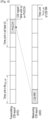
- Fig. 1 schematically illustrates a structure of a frame under time division duplex (TDD) mode of LTE.
- TDD time division duplex
- each radio frame 105 is 10 milliseconds (ms), which is divided equally into two half-frames each having a length of 5ms.
- Each half-frame (or semi-frame) 110 comprises five subframes (also referred to as SFs) each having a length of 1ms, and one of the five subframes is a special subframe 115.
- the special subframe 115 comprises 3 special parts which are downlink pilot time slot (DwPTS) 120, guard period (GP) 125 and uplink pilot time slot (UpPTS) 130 respectively.
- DwPTS downlink pilot time slot
- GP guard period
- UpPTS uplink pilot time slot
- Each of the subframes other than the special subframe comprises 2 time slots each having a length of 0.5ms.
- Each of the radio subframes other than the special subframe can be allocated to either uplink (from user equipment to base station) or downlink (from base station to user equipment) transmission.
- the subframe allocated to uplink transmission may be referred to as uplink subframe, and the subframe allocated to downlink transmission may be referred to as downlink subframe.
- Fig. 2 is a flow chart illustrating a method for transmitting channel state information according to an exemplary embodiment of the present disclosure.
- the method for transmitting channel state information (CSI) report comprises the steps of:
- Step 101 determining CSI transmission configuration information that comprises transmission times k of a periodic CSI report in one subframe.
- Step 102 transmitting a CSI report according to the CSI transmission configuration information.
- the UE determines a cell for transmitting uplink control information (UCI), and then determines the CSI transmission configuration information according to the cell for transmitting the UCI.
- the UCI comprises the CSI report, hybrid automatic retransmission request-acknowledgement (HARQ-ACK), scheduling request (SR) and the like.
- the UE receives a higher layer signaling such as a radio resource control (RRC) layer signaling to determine the cell (i.e., an assistant cell configured by a base station) for transmitting UCI, and transmits UCI in the cell. If UE fails to receive the cell indicated by the RRC layer signaling, it transmits UCI in a main cell where it is located currently.
- RRC radio resource control
- the UE determines CSI transmission configuration information by receiving information transmitted by the base station of the cell.
- UE For non-periodic CSI report, UE receives CSI request information transmitted by a base station of the cell where it is located currently from downlink control information (DCI) used by the base station to schedule a PUSCH, and transmits the non-periodic CSI report to a base station of a cell according to an indication from the CSI request information,.
- DCI downlink control information
- CSI transmission configuration information comprises transmission times k of the periodic CSI report in one subframe (because UE transmits periodic CSI report on a PUCCH, the transmission times k of the periodic CSI report in one subframe is equal to the transmission times of the PUCCH in one subframe), and comprises one or more of a time offset N OFFSET1 of CSI report time domain position relative to a first reference point, a time unit U OFFSET1 of N OFFSET1 , a transmission period N p of the periodic CSI report, a time unit U p of N p , a time offset N CQI_ref of CSI report time domain position relative to a time domain position of corresponding CSI reference resource (also referred to as CSI RR), a time unit U CQI_ref of N CQI_ref , and a time unit U of time correspondence between CSI reference resource and CSI report.
- CSI RR time unit U CQI_ref of N CQI_ref
- N OFFSET1 is an integral multiple of U OFFSTE1
- N p is an integral multiple of U p
- N CQI_ref is an integral multiple of U CQ1_ref
- U p may be a length of a subframe, a length of a time slot or a length of an orthogonal frequency division multiplexing (OFDM) symbol.
- OFDM orthogonal frequency division multiplexing
- the UE determines the transmission times k of periodic CSI report in one subframe according to one or more of an indication from a received RRC layer signaling, an indication from a media access control (MAC) layer signaling, an indication from system information, a predefined rule in a protocol, and an attribute of resource for transmitting PUCCH.
- the attribute of resource for transmitting PUCCH may be a space size of a subcarrier for transmitting a PUCCH
- UE may determine the transmission times k of periodic CSI report in one subframe according to the space size of the subcarrier for transmitting the PUCCH.
- the UE determines the time offset N OFFSET1 of the time-domain position of CSI report relative to the first reference point, the time unit U OFFSET1 of N OFFSET1 , the transmission period N p of periodic CSI report or the time unit U p of N p according to one of the indication from the received RRC layer signaling, the indication from the received MAC layer signaling, the indication from the received system information, the predefined rule in the protocol, and the transmission times k of periodic CSI report in one subframe.
- the UE determines the time offset N CQI_ref of the time-domain position of CSI report relative to the time-domain position of corresponding CSI report according to one of the indication from the received RRC layer signaling, the indication from the received MAC layer signaling, the indication from the received physical layer signaling, the indication from the received system information, the predefined rule in the protocol, the attribute of resource for transmitting PUCCH and the attribute of CSI reference resource.
- the attribute of CSI reference resource comprises the space size of the subcarrier for transmitting CSI reference resource and/or the time unit U CQI_ref of N CQI_ref .
- N CQI_ref is an integral multiple of U CQI_ref .
- the UE determines the time unit U of time correspondence between CSI reference resource and CSI report according to one of the indication from the received RRC layer signaling, the indication from the received MAC layer signaling, the indication from the received physical layer signaling, the indication from the received system information, the predefined rule in the protocol, as well as respective values of U OFFSET1 , U P and U CQI_ref .
- U UE determines the time unit U of time correspondence between CSI reference resource and CSI report according to respective values of U OFFSETI , U P and U CQI_ref comprises determining U to be equal to one of U OFFSTE1 , U p , U CQI_ref , a maximum among U OFFSETI , U P and U CQI_ref , and a minimum among U OFFSETI , U P and U CQI_ref .
- the CSI report is transmitted according to the CSI transmission configuration information in step 102.
- the UE finds the CSI reference resource according to a time-frequency position indicated by CSI transmission configuration information, measures the channel state information-reference signal (CSI-RS) in CSI reference resource, and feedbacks the reported CSI back to base station according to measure results.
- CSI-RS channel state information-reference signal
- cqi-pmi-ConfigIndex I CQI / PMI Value of N p (with time unit of T p ) Value of N OFFSET1 (with time unit of T p ) 0 ⁇ I CQI / PMI ⁇ 1 2 I CQI / PMI 2 ⁇ I CQI / PMI ⁇ 11 10 I CQI / PMI - 2 12 ⁇ I CQI / PMI ⁇ 31 20 I CQI / PMI -12 32 ⁇ I CQI / PMI ⁇ 71 40 I CQI / PMI -32 72 ⁇ I CQI / PMI ⁇ 151 80 I CQI / PMI - 72 152 ⁇ I CQI / PMI ⁇ 311 160 I CQI / PMI -152 312 ⁇ I CQI / PMI ⁇ 631 320 I CQI / PMI -312 632 ⁇ I CQI / PMI
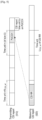
- the CSI reference resource is in the time unit n-N CQI_ref .
- all or some of the CSI reference resource may be transmitted during the time unit n-N CQI_ref .
- the PUCCH for transmitting periodic CSI report 710 is transmitted during the time unit n
- a preceding part of CSI reference resource 720 is transmitted during the time unit n-N CQI_ref .
- the time unit n-N CQI_ref is an effective downlink time unit or a special time unit.
- N CQI_ref satisfies the condition of N CQI_ref ⁇ S1.
- UE reports CSI report on a PUCCH(s) or a PUSCH(s) during a time unit n
- all or some of the PUCCH(s) or PUSCH(s) may be transmitted during the time unit n.
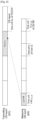
- UE configures transmission mode 10 and a plurality of CSI report processes, and the CSI reference resource of each CSI report process is in the time unit n-N CQI_ref .
- a preceding part of the PUCCH for transmitting periodic CSI report 810 is transmitted during the time unit n
- CSI reference resource 820 is transmitted during the time unit n-N CQI_ref .
- the time unit n-N CQI_ref is an effective downlink time unit or a special time unit.
- N CQI_ref satisfies the condition of N CQI_ref ⁇ S2.
- N CQI_ref satisfies the condition of N CQI_ref ⁇ S1.
- N CQI_ref satisfies the condition of N CQI_ref ⁇ S2.
- the CSI reference resource is in the time unit n-N CQI_ref .
- all of some of the CSI reference resource may be transmitted during the time unit n-N CQI_ref .
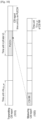
- the PUCCH for transmitting periodic CSI report 910 is transmitted during the time unit n
- a preceding part of CSI reference resource 920 is transmitted during the time unit n-N CQI_ref .
- the time unit n-N CQI_ref is an effective downlink time unit or a special time unit.
- N CQI_ref satisfies the condition of N CQI_ref ⁇ S1.
- the CSI reference resource of each CSI report process is in the time unit n-N CQI_ref .
- all or some of the CSI reference resource may be transmitted during the time unit n-N CQI_ref .
- the PUCCH for transmitting periodic CSI report 910 is transmitted during the time unit n
- a preceding part of CSI reference resource 920 is transmitted during the time unit n-N CQI_ref .
- the time unit n-N CQI_ref is an effective downlink time unit or a special time unit.
- N CQI_ref satisfies the condition of N CQI_ref ⁇ S2.
- N CQI_ref satisfies the condition of N CQI_ref ⁇ S1.
- N CQI_ref satisfies the condition of N CQI_ref ⁇ S2.
- the PUCCH or the PUSCH may be transmitted throughout the time unit n or during a part of the time unit n.
- the CSI reference resource is in the time unit n-N CQI_ref .
- the CSI reference resource may be transmitted throughout the time unit n-N CQI_ref or during a part of the time unit n-N CQI_ref . For example, as shown in Fig.
- the PUCCH for transmitting periodic CSI report 1010 is transmitted during the time unit n, and the CSI reference resource 1020 is transmitted during an earlier part of the time unit n-N CQI_ref .
- the time unit n-N CQI_ref is an effective downlink time unit or a special time unit.
- N CQI_ref satisfies the condition of N CQI_ref ⁇ S1.
- the PUCCH or the PUSCH may be transmitted throughout the time unit n or during a part of the time unit n.
- CSI reference resource of each CSI report process is in the time unit n-N CQI_ref .
- CSI reference resource may be transmitted throughout the time unit n-N CQI_ref or during a part of the time unit n-N CQI_ref . For example, as shown in Fig.
- the PUCCH for transmitting periodic CSI report 1010 is transmitted during the time unit n, and CSI reference resource 1020 is transmitted during a preceding part of the time unit n-N CQI_ref .
- the time unit n-N CQI_ref is an effective downlink time unit or a special time unit.
- N CQI_ref satisfies the condition of NCQI_ref ⁇ S2.
- N CQI_ref satisfies the condition of N CQI_ref ⁇ S1.
- N CQI_ref satisfies the condition of N CQI_ref ⁇ S2.
- the CSI reference resource is in the time unit n-N CQI_ref . In such a situation, all or some of the CSI reference resource may be transmitted during the time unit N-N CQI_ref . For example, as shown in Fig.
- a preceding part of PUCCH for transmitting periodic CSI report 1110 is transmitted during the time unit n
- CSI reference resource 1120 is transmitted during the time unit n-N CQI_ref .
- the time unit n-N CQI_ref is an effective downlink time unit or a special time unit.
- N CQI_ref satisfies the condition of N CQI_ref ⁇ S1.
- CSI reference resource of each CSI report process is in the time unit n-N CQI_ref .
- all or some of the CSI reference resource may be transmitted during the time unit n-N CQI_ref .
- a preceding part of the PUCCH for transmitting periodic CSI report 1110 is transmitted during the time unit n, and the CSI reference resource 1120 is transmitted during the time unit n-N CQI_ref .
- the time unit n-N CQI_ref is an effective downlink time unit or a special time unit.
- N CQI_ref satisfies the condition of N CQI_ref ⁇ S2.
- N CQI_ref satisfies the condition of N CQI_ref ⁇ S1.
- N CQI_ref satisfies the condition of N CQ1_ref ⁇ S2.
- N CQI_ref time offset N CQI_ref of CSI report time domain position relative to the time domain position of CSI reference resource. Because time unit for CSI report measurement and time unit for PUCCH preparation may be different due to different durations of the time unit of the CSI reference resource and of the time unit of PUCCH, it is necessary to determine a minimum time delay (N CQI_ref ) between the CSI reference resource and the CSI report according to the time unit (U CQI_ref ) of the CSI reference resource and the time unit (i.e., U p ) of the PUCCH for the CSI report .
- N CQI_ref minimum time delay
- N CQI_ref may be determined according to the transmission mode configured by UE and the number of CSI report process in the way described in the exemplary embodiment 3 or 4.
- N CQI_ref satisfies the condition of N CQI_ref ⁇ S, wherein S is a positive integer.
- the value of S depends on the transmission mode configured by UE and the number of CSI report processes. Specifically, when UE configures transmission modes 1-9 or configures transmission mode 10 but only one CSI report process, S is equal to S1; and when UE configures transmission mode 10 and more than one CSI report processes, S is equal to S2.
- Respective values of S1 and S2 may be determined in the way described in the exemplary embodiment 3 or 4.
- the respective values of S1 and S2 depends on neither U CQI_ref nor U p . This is because the value of S1 and that of S2 are same when the transmission modes configured for respective cells are same and the numbers of CSI report processes configured by respective cells in which a plurality of CSI report processes are configured are same.
- a piece of effective CSI reference resource may be selected according to a predefined rule. For example, the last reference resource may be selected to obtain a more accurate measured CS, or the earliest reference resource may be selected to decrease the time delay of process.
- the time unit U of the CSI reference resource corresponding to CSI report may be determined in a way described in the exemplary embodiment 3 or 4 (U may be specified by base station, or determined according to the values of U p , U OFFSET1 and U CQI_ref ). Then, N CQI_ref may be determined according to transmission mode and the number of CSI report processes configured by UE, the time unit (U p ) of the PUCCH for transmitting CSI report and the time unit (i.e., U CQI_ref ) of the CSI reference resource. N CQI_ref satisfies the condition of N CQI_ref ⁇ S, wherein S is a positive integer. Two examples are provided hereinafter to illustrate how to determine.
- Figs. 12 and 13 schematically illustrate corresponding relationships between periodic CSI report and CSI reference resource in an exemplary embodiment 7 respectively.
- the time unit of the time correspondence between CSI reference resource (e.g., CSI-RS) and CSI report is an absolute time unit (e.g., microsecond ( ⁇ s), or time domain sampling value (e.g., 1/4096*480*1000 second)).
- the CSI reference resource on which the CSI report is based is CSI reference resource before the CSI report, and the time interval N CQI_ref between the start position of the time slot in which the PUCCH for transmitting CSI report is transmitted and the end position of the time slot in which the CSI reference resource is transmitted, satisfies a condition of N CQI_ref ⁇ S (S is an absolute time interval, e.g., 2 milliseconds or 2.5 milliseconds).
- the value of S may be configured by a UE specific higher layer signaling, predefined by a protocol, or determined in other ways. For different cells, the value of S may be configured independently, and configuring the value of S independently may achieve a better effect, since the subcarrier spaces of different cells are different, or the number of CSI report processes configured or the time delay of CSI report calculation processes may vary among different cells. A same value of S may be configured for different cells for the sake of simplicity).
- N CQI_ref is a minimum value that can satisfy the above condition.
- the time interval between the start position 1205 of the time slot m in which the PUCCH for transmitting CSI report is transmitted and the end position of the time slot a in which the CSI reference resource is transmitted is smaller than S, therefore the CSI reference resource transmitted in the time slot a is not the reference resource for the CSI reported in the time slot m;
- the time interval between the start position 1205 of the time slot m in which the PUCCH for transmitting CSI report is transmitted and the end position of the time slot b in which the CSI reference resource is transmitted, is larger than S, and the end position of time slot b is nearest to the start position 1205 of the time slot m for the PUCCH, therefore the CSI reference resource of the time slot b is the reference resource for the CSI reported in the time slot m;
- the time interval between the start position 1205 of the time slot m in which the PUCCH for transmitting CSI report is transmitted and the end position of the time slot c in which the CSI reference resource is transmitted is larger
- the time unit of the time correspondence between CSI reference resource (e.g., CSI-RS) and CSI report is an absolute time unit (e.g., microsecond ( ⁇ s), or time domain sampling value (e.g., 1/4096*480*1000 second)).
- the CSI reference resource on which the CSI report is based is CSI reference resource before the CSI report, and the time interval N CQI_ref between the start position of the first OFDM symbol in which the PUCCH for transmitting CSI report is transmitted and the end position of the last OFDM symbol in which the CSI reference resource is transmitted, satisfies a condition of N CQI_ref ⁇ S (S is an absolute time interval, e.g., 2 milliseconds or 2.5 milliseconds).
- S is an absolute time interval, e.g., 2 milliseconds or 2.5 milliseconds.
- the value of S may be configured by a UE specific higher layer signaling, predefined by a protocol, or determined in other ways.
- the value of S may be configured independently, and configuring the value of S independently may achieve a better effect, since the subcarrier spaces of different cells are different, the number of CSI report processes configured or the time delay of CSI report calculation processes may vary among different cells. A same value of S may be configured for different cells for the sake of simplicity).
- N CQI_ref is a minimum value that can satisfy above condition.
- the time interval between the start position 1305 of the first OFDM symbol of the PUCCH in the time slot m in which the PUCCH for transmitting CSI report is transmitted and the end position 1310 of the last OFDM symbol of the CSI reference resource in the time slot a in which the CSI reference resource is transmitted is smaller than S, therefore the CSI reference resource transmitted in the time slot a is not the reference resource for the CSI reported in the time slot m;
- the time interval between the start position 1305 of the first OFDM symbol of PUCCH in the time slot m in which the PUCCH for transmitting CSI report is transmitted and the end position 1310 of the last OFDM symbol for transmitting CSI reference resource in the time slot b is larger than S, and the end position 1310 of the last OFDM symbol for transmitting CSI reference resource in the time slot b is nearest to the start position 1305 of the first OFDM symbol of PUCCH in the time slot m of PUCCH, therefore the CSI reference resource transmitted in the time slot b
- Fig. 14 is a block diagram illustrating a user equipment for transmitting channel state information report according to an exemplary embodiment of the present disclosure.
- the UE comprises:
- the operations of the configuration determining module 1405 and the CSI report transmitting module 1410 correspond respectively to the step 101 and step 102 of the method for CSI report described above.
- embodiments of the present disclosure has at least the following advantageous technical effects as compared to the prior art:
- Units that are described individually may be physically separated or not.
- a component illustrated as a unit may be a physical unit or not, that is, it can be located at one place or distributed on a plurality of network units. Some or all of the units may be selected as required in order to achieve the objects of the embodiments.
- each function unit in each embodiment of the present disclosure can be integrated into one processing unit or individually exist physically.
- two or more units may be integrated into one unit.
- the above integrated unit may be implemented through either hardware or a software functional unit.
- the computer-readable recording medium may be a data storage device, which can store data which can be read by a computer system.
- Examples of the computer readable recording medium may include a Read-Only Memory (ROM), a Random Access Memory (RAM), a CD-ROM, a magnetic tape, a floppy disk, an optical data storage device, and a carrier wave (such as data transmission through the Internet).
- the computer-readable recording medium may be distributed through computer systems connected to the network, and accordingly, the computer-readable code may be stored and executed in a distributed manner. Further, functional programs, codes and code segments for achieving the present disclosure may be easily interpreted by programmers skilled in the art which the present disclosure pertains to.
- any such software may be stored, e.g., in a volatile or non-volatile storage device such as a ROM, a memory such as a RAM, a memory chip, a memory device, or a memory IC, or a recordable optical or magnetic medium such as a CD, a DVD, a magnetic disk, or a magnetic tape, regardless of its ability to be erased or its ability to be re-recorded.
- a method according to an embodiment of the present disclosure may be implemented by a computer or portable terminal including a controller and a memory, wherein the memory is one example of machine-readable storage media suitable to store a program or programs including instructions for implementing the embodiments of the present disclosure.
- the present disclosure includes a program for a code that implements the apparatus and method described in the appended claims of the specification and a machine (a computer or the like)-readable storage medium for storing the program.
- the program may be electronically carried by any medium such as a communication signal transferred through a wired or wireless connection, and the present disclosure appropriately includes equivalents thereof.
- an apparatus may receive the program from a program providing device that is wiredly or wirelessly connected thereto, and may store the program.
- the program providing device may include a program including instructions through which a program processing device performs a preset content protecting method, a memory for storing information required for the content protecting method, a communication unit for performing wired or wireless communication with the program processing device, and a controller for transmitting the corresponding program to a transceiver at the request of the program processing device or automatically.
Landscapes
- Engineering & Computer Science (AREA)
- Signal Processing (AREA)
- Computer Networks & Wireless Communication (AREA)
- Quality & Reliability (AREA)
- Mobile Radio Communication Systems (AREA)
Claims (15)
- Verfahren, das von einem Endgerät zum Übertragen eines Kanalzustandsinformations(CSI)-Berichts in einem drahtlosen Kommunikationssystem ausgeführt wird, wobei das Verfahren Folgendes umfasst:Empfangen von Informationen über eine Uplink-Unterträgerraumgröße und Informationen über eine Downlink-Unterträgerraumgröße von einer Basisstation;Identifizieren einer CSI-Referenzressource in einem ersten Downlink-Slot, der einem zweiten Downlink-Slot um einen Zeitversatz vorausgeht, wobei der zweite Downlink-Slot einem Uplink-Slot für eine CSI-Berichterstattung entspricht;Empfangen eines CSI-Referenzsignals, CSI-RS, auf der identifizierten CSI-Referenzressource von der Basisstation; undÜbertragen des CSI-Berichts für das empfangene CSI-RS in dem Uplink-Slot basierend auf der Uplink-Unterträgerraumgröße auf einem physikalischen Uplink-Steuerungskanal, PUCCH, an die Basisstation,wobei der Zeitversatz ein kleinster Wert ist, der größer als oder gleich einer positiven Ganzzahl ist, die basierend auf der Downlink-Unterträgerraumgröße identifiziert wird, falls es sich bei der CSI-Berichterstattung um eine periodische CSI-Berichterstattung handelt.
- Verfahren nach Anspruch 1, wobei, falls die Downlink-Unterträgerraumgröße größer als oder gleich der Uplink-Unterträgerraumgröße ist, mindestens zwei Downlink-Slots einschließlich des zweiten Downlink-Slots dem Uplink-Slot für den PUCCH (810, 820) entsprechen, und
wobei der zweite Downlink-Slot ein früherer unter den mindestens zwei Downlink-Slots ist. - Verfahren nach Anspruch 1, wobei, falls die Downlink-Unterträgerraumgröße kleiner als die Uplink-Unterträgerraumgröße ist, der zweite Downlink-Slot mindestens zwei Uplink-Slots einschließlich des Uplink-Slots für den PUCCH (910, 920) entspricht.
- Verfahren nach Anspruch 1, wobei der erste Downlink-Slot ferner basierend auf der Uplink-Unterträgerraumgröße identifiziert wird.
- Verfahren, das von einer Basisstation zum Empfangen eines Kanalzustandsinformations(CSI)-Berichts in einem drahtlosen Kommunikationssystem ausgeführt wird, wobei das Verfahren Folgendes umfasst:Übertragen von Informationen über eine Uplink-Unterträgerraumgröße und Informationen über eine Downlink-Unterträgerraumgröße an ein Endgerät;Übertragen eines CSI-Referenzsignals, CSI-RS, auf einer CSI-Referenzressource an das Endgerät; undEmpfangen des CSI-Berichts für das übertragene CSI-RS in einem Uplink-Slot basierend auf der Uplink-Unterträgerraumgröße auf einem physikalischen Uplink-Steuerungskanal, PUCCH, von dem Endgerät,wobei sich die CSI-Referenzressource in einem ersten Downlink-Slot befindet, der einem zweiten Downlink-Slot um einen Zeitversatz vorausgeht,wobei der zweite Downlink-Slot dem Uplink-Slot für eine CSI-Berichterstattung entspricht, undwobei der Zeitversatz ein kleinster Wert ist, der größer als oder gleich einer positiven Ganzzahl ist, abhängig von der Downlink-Unterträgerraumgröße, falls es sich bei der CSI-Berichterstattung um eine periodische CSI-Berichterstattung handelt.
- Verfahren nach Anspruch 5, wobei, falls die Downlink-Unterträgerraumgröße größer als oder gleich der Uplink-Unterträgerraumgröße ist, mindestens zwei Downlink-Slots einschließlich des zweiten Downlink-Slots dem Uplink-Slot für den PUCCH (810, 820) entsprechen, wobei der zweite Downlink-Slot ein früherer unter den mindestens zwei Downlink-Slots ist, und
wobei, falls die Downlink-Unterträgerraumgröße kleiner als die Uplink-Unterträgerraumgröße ist, der zweite Downlink-Slot mindestens zwei Uplink-Slots einschließlich des Uplink-Slots für den PUCCH (910, 920) entspricht. - Verfahren nach Anspruch 5, wobei der erste Downlink-Slot ferner basierend auf der Uplink-Unterträgerraumgröße identifiziert wird.
- Endgerät zum Übertragen eines Kanalzustandsinformations(CSI)-Berichts in einem drahtlosen Kommunikationssystem, wobei das Endgerät Folgendes umfasst:einen Transceiver; undeinen Prozessor, der mit dem Transceiver gekoppelt und zu Folgendem konfiguriert ist:Empfangen von Informationen über eine Uplink-Unterträgerraumgröße und Informationen über eine Downlink-Unterträgerraumgröße von einer Basisstation,Identifizieren einer CSI-Referenzressource in einem ersten Downlink-Slot, der einem zweiten Downlink-Slot um einen Zeitversatz vorausgeht, wobei der zweite Downlink-Slot einem Uplink-Slot für eine CSI-Berichterstattung entspricht,Empfangen eines CSI-Referenzsignals, CSI-RS, auf der identifizierten CSI-Referenzressource von der Basisstation, undÜbertragen des CSI-Bericht für das empfangene CSI-RS in dem Uplink-Slot basierend auf der Uplink-Unterträgerraumgröße auf einem physikalischen Uplink-Steuerungskanal, PUCCH, an die Basisstation,wobei der Zeitversatz ein kleinster Wert ist, der größer als oder gleich einer positiven Ganzzahl ist, die basierend auf der Downlink-Unterträgerraumgröße identifiziert wird, falls es sich bei der CSI-Berichterstattung um eine periodische CSI-Berichterstattung handelt.
- Endgerät nach Anspruch 8, wobei, falls die Downlink-Unterträgerraumgröße größer als oder gleich der Uplink-Unterträgerraumgröße ist, mindestens zwei Downlink-Slots einschließlich des zweiten Downlink-Slots dem Uplink-Slot für den PUCCH (810, 820) entsprechen, und
wobei der zweite Downlink-Slot ein früherer unter den mindestens zwei Downlink-Slots ist. - Endgerät nach Anspruch 8, wobei, falls die Downlink-Unterträgerraumgröße kleiner als die Uplink-Unterträgerraumgröße ist, der zweite Downlink-Slot mindestens zwei Uplink-Slots einschließlich des Uplink-Slots für den PUCCH (910, 920) entspricht.
- Endgerät nach Anspruch 8, wobei der erste Downlink-Slot ferner basierend auf der Uplink-Unterträgerraumgröße identifiziert wird.
- Basisstation zum Empfangen eines Kanalzustandsinformations(CSI)-Berichts in einem drahtlosen Kommunikationssystem, wobei die Basisstation Folgendes umfasst:einen Transceiver, der zum Übertragen oder Empfangen eines Signals konfiguriert ist; undeinen Prozessor, der mit dem Transceiver gekoppelt und zu Folgendem konfiguriert ist:Übertragen von Informationen über eine Uplink-Unterträgerraumgröße und Informationen über eine Downlink-Unterträgerraumgröße an ein Endgerät,Übertragen eines CSI-Referenzsignals, CSI-RS, auf einer CSI-Referenzressource an das Endgerät, undEmpfangen des CSI-Berichts für das übertragene CSI-RS in einem Uplink-Slot basierend auf der Uplink-Unterträgerraumgröße auf einem physikalischen Uplink-Steuerungskanal, PUCCH, von dem Endgerät,wobei sich die CSI-Referenzressource in einem ersten Downlink-Slot befindet, der einem zweiten Downlink-Slot um einen Zeitversatz vorausgeht,wobei der zweite Downlink-Slot dem Uplink-Slot für eine CSI-Berichterstattung entspricht, undwobei der Zeitversatz ein kleinster Wert ist, der größer als oder gleich einer positiven Ganzzahl ist, abhängig von der Downlink-Unterträgerraumgröße, falls es sich bei der CSI-Berichterstattung um eine periodische CSI-Berichterstattung handelt.
- Basisstation nach Anspruch 12, wobei, falls die Downlink-Unterträgerraumgröße größer als oder gleich der Uplink-Unterträgerraumgröße ist, mindestens zwei Downlink-Slots einschließlich des zweiten Downlink-Slots dem Uplink-Slot für den PUCCH (810, 820) entsprechen, und
wobei der zweite Downlink-Slot ein früherer unter den mindestens zwei Downlink-Slots ist. - Basisstation nach Anspruch 12, wobei, falls die Downlink-Unterträgerraumgröße kleiner als die Uplink-Unterträgerraumgröße ist, der zweite Downlink-Slot mindestens zwei Uplink-Slots einschließlich des Uplink-Slots für den PUCCH (910, 920) entspricht.
- Basisstation nach Anspruch 12, wobei der erste Downlink-Slot ferner basierend auf der Uplink-Unterträgerraumgröße identifiziert wird.
Applications Claiming Priority (3)
| Application Number | Priority Date | Filing Date | Title |
|---|---|---|---|
| CN201710057368 | 2017-01-26 | ||
| CN201710825445.7A CN108365915B (zh) | 2017-01-26 | 2017-09-14 | 信道状态信息传输的方法及用户设备 |
| PCT/KR2018/000483 WO2018139785A1 (en) | 2017-01-26 | 2018-01-10 | Method and user equipment for transmitting channel state information |
Publications (4)
| Publication Number | Publication Date |
|---|---|
| EP3566352A1 EP3566352A1 (de) | 2019-11-13 |
| EP3566352A4 EP3566352A4 (de) | 2020-06-17 |
| EP3566352C0 EP3566352C0 (de) | 2025-04-02 |
| EP3566352B1 true EP3566352B1 (de) | 2025-04-02 |
Family
ID=63009996
Family Applications (1)
| Application Number | Title | Priority Date | Filing Date |
|---|---|---|---|
| EP18744987.1A Active EP3566352B1 (de) | 2017-01-26 | 2018-01-10 | Verfahren und benutzergerät zur übertragung von kanalzustandsinformationen |
Country Status (4)
| Country | Link |
|---|---|
| US (1) | US11489574B2 (de) |
| EP (1) | EP3566352B1 (de) |
| KR (1) | KR102496114B1 (de) |
| CN (1) | CN108365915B (de) |
Families Citing this family (7)
| Publication number | Priority date | Publication date | Assignee | Title |
|---|---|---|---|---|
| WO2018227614A1 (en) * | 2017-06-16 | 2018-12-20 | Qualcomm Incorporated | Channel state information feedback for flexible uplink control signaling |
| RU2758075C1 (ru) | 2018-01-12 | 2021-10-26 | Телефонактиеболагет Лм Эрикссон (Пабл) | Конфигурация ресурса запроса планирования |
| KR102581065B1 (ko) | 2018-05-07 | 2023-09-20 | 광동 오포 모바일 텔레커뮤니케이션즈 코포레이션 리미티드 | 자원 위치 결정 방법, 단말 기기 및 네트워크 기기 |
| CN110971382B (zh) | 2018-09-30 | 2023-04-07 | 维沃移动通信有限公司 | 一种确定信道状态信息csi处理单元占用时间的方法、终端设备 |
| WO2020063211A1 (zh) * | 2018-09-30 | 2020-04-02 | 维沃移动通信有限公司 | 确定信道状态信息csi处理单元占用时间的方法、终端设备 |
| CN111757479B (zh) | 2019-03-29 | 2022-10-11 | 华为技术有限公司 | 通信的方法及装置 |
| WO2022154611A1 (ko) * | 2021-01-15 | 2022-07-21 | 엘지전자 주식회사 | Csi 보고를 전송하는 방법, 사용자기기, 프로세싱 장치, 저장 매체 및 컴퓨터 프로그램, 그리고 csi 보고를 수신하는 방법 및 기지국 |
Family Cites Families (12)
| Publication number | Priority date | Publication date | Assignee | Title |
|---|---|---|---|---|
| US9509475B2 (en) * | 2012-09-09 | 2016-11-29 | Lg Electronics Inc. | Method and apparatus for transmitting and receiving data |
| US10904780B2 (en) | 2013-07-09 | 2021-01-26 | Lg Electronics Inc. | Method and apparatus for measuring channel status in wireless communication system supporting reconfiguration of usage of radio resource |
| CN105099632B (zh) * | 2014-04-23 | 2019-12-13 | 北京三星通信技术研究有限公司 | 一种上行探测参考信号传输的方法和设备 |
| US10505608B2 (en) * | 2015-02-26 | 2019-12-10 | Lg Electronics Inc. | Method for feeding back CSI information in wireless communication system, and apparatus therefor |
| US10425204B2 (en) * | 2015-03-13 | 2019-09-24 | Samsung Electronics Co., Ltd. | Method and apparatus for measuring channel state information in communication system |
| US10263671B2 (en) * | 2015-12-31 | 2019-04-16 | Lg Electronics Inc. | Method for reporting reference signal indicator to base station by terminal in wireless communication system and apparatus therefor |
| KR102248076B1 (ko) * | 2016-07-26 | 2021-05-04 | 엘지전자 주식회사 | 무선 통신 시스템에서 채널 상태 보고를 위한 방법 및 이를 위한 장치 |
| BR112019002369B1 (pt) * | 2016-08-05 | 2023-01-31 | Lg Electronics Inc | Método para um equipamento de usuário para realizar um tipo adicional de operação e equipamento de usuário configurado para realizar um tipo adicional de operação |
| JP2019532545A (ja) * | 2016-08-11 | 2019-11-07 | エルジー エレクトロニクス インコーポレイティド | 無線通信システムにおいてチャンネル状態報告のための方法及びそのための装置 |
| US10334533B2 (en) * | 2016-11-02 | 2019-06-25 | At&T Intellectual Property I, L.P. | Non-orthogonal design for channel state information reference signals for a 5G air interface or other next generation network interfaces |
| US10932276B2 (en) * | 2016-11-03 | 2021-02-23 | Convida Wireless, Llc | Frame structure in NR |
| US10892808B2 (en) * | 2017-01-06 | 2021-01-12 | Ntt Docomo, Inc. | Method of acquiring channel state information |
-
2017
- 2017-09-14 CN CN201710825445.7A patent/CN108365915B/zh active Active
-
2018
- 2018-01-10 US US16/345,540 patent/US11489574B2/en active Active
- 2018-01-10 EP EP18744987.1A patent/EP3566352B1/de active Active
- 2018-01-10 KR KR1020197010146A patent/KR102496114B1/ko active Active
Also Published As
| Publication number | Publication date |
|---|---|
| EP3566352C0 (de) | 2025-04-02 |
| EP3566352A4 (de) | 2020-06-17 |
| EP3566352A1 (de) | 2019-11-13 |
| CN108365915A (zh) | 2018-08-03 |
| US20190312622A1 (en) | 2019-10-10 |
| CN108365915B (zh) | 2023-04-07 |
| US11489574B2 (en) | 2022-11-01 |
| KR102496114B1 (ko) | 2023-02-06 |
| KR20190103140A (ko) | 2019-09-04 |
Similar Documents
| Publication | Publication Date | Title |
|---|---|---|
| US12356212B2 (en) | Method and apparatus for repeating uplink transmission for network cooperative communication | |
| EP3566352B1 (de) | Verfahren und benutzergerät zur übertragung von kanalzustandsinformationen | |
| US12231362B2 (en) | Method and apparatus for signal transmission to high speed mobile UE in a wireless communication system | |
| CN110073704B (zh) | 基站装置、终端装置、通信方法以及集成电路 | |
| US20200314691A1 (en) | Hybrid automatic repeat request acknowledge resource allocation for enhanced physical downlink control channel | |
| CN109997381B (zh) | 基站装置、终端装置以及通信方法 | |
| EP3455991B1 (de) | Konfiguration von downlink-übertragungen | |
| EP3217711B1 (de) | Basisstationsvorrichtung, endgerätevorrichtung und kommunikationsverfahren | |
| CN106068668A (zh) | 在无线通信系统中执行设备到设备通信的方法和装置 | |
| JP6789305B2 (ja) | 基地局装置、端末装置および通信方法 | |
| CN101594683A (zh) | 一种载波聚合时的信号传输方法及系统 | |
| US12232117B2 (en) | Method for indicating time difference between PUCCH and PDSCH, base station, and readable medium | |
| CN106233773A (zh) | 基站装置及其传输方法 | |
| CN110178400B (zh) | 基站装置、终端装置和通信方法 | |
| CN113206730A (zh) | 传输参考信号的方法和通信设备 | |
| WO2017169467A1 (ja) | 基地局装置、端末装置および通信方法 | |
| EP4145747A1 (de) | Kommunikationsverfahren und -vorrichtung | |
| CN106685616A (zh) | 测量参考信号srs的发送方法及装置 | |
| US20230053430A1 (en) | Methods for handling special relations for pucch resources belonging to multiple pucch configurations | |
| WO2018173000A1 (en) | Signaling of srs resources for pusch rate matching | |
| JPWO2016072389A1 (ja) | 基地局装置、端末装置および通信方法 | |
| CN106411375B (zh) | Srs的指示发送方法、srs的发送方法和装置 | |
| JP6028076B2 (ja) | 移動局装置、基地局装置、無線通信システム、無線通信方法および集積回路 | |
| WO2016200296A1 (en) | Outer loop link adaptation with prediction of interferences generated by csi-rs | |
| CN107734671A (zh) | 用户设备及下行数据的harq反馈方法 |
Legal Events
| Date | Code | Title | Description |
|---|---|---|---|
| STAA | Information on the status of an ep patent application or granted ep patent |
Free format text: STATUS: THE INTERNATIONAL PUBLICATION HAS BEEN MADE |
|
| PUAI | Public reference made under article 153(3) epc to a published international application that has entered the european phase |
Free format text: ORIGINAL CODE: 0009012 |
|
| STAA | Information on the status of an ep patent application or granted ep patent |
Free format text: STATUS: REQUEST FOR EXAMINATION WAS MADE |
|
| 17P | Request for examination filed |
Effective date: 20190807 |
|
| AK | Designated contracting states |
Kind code of ref document: A1 Designated state(s): AL AT BE BG CH CY CZ DE DK EE ES FI FR GB GR HR HU IE IS IT LI LT LU LV MC MK MT NL NO PL PT RO RS SE SI SK SM TR |
|
| AX | Request for extension of the european patent |
Extension state: BA ME |
|
| DAV | Request for validation of the european patent (deleted) | ||
| DAX | Request for extension of the european patent (deleted) | ||
| REG | Reference to a national code |
Ref country code: DE Ref legal event code: R079 Free format text: PREVIOUS MAIN CLASS: H04L0001060000 Ipc: H04L0001000000 |
|
| A4 | Supplementary search report drawn up and despatched |
Effective date: 20200515 |
|
| RIC1 | Information provided on ipc code assigned before grant |
Ipc: H04L 1/06 20060101ALI20200511BHEP Ipc: H04B 7/06 20060101ALI20200511BHEP Ipc: H04L 5/00 20060101ALI20200511BHEP Ipc: H04L 1/00 20060101AFI20200511BHEP |
|
| STAA | Information on the status of an ep patent application or granted ep patent |
Free format text: STATUS: EXAMINATION IS IN PROGRESS |
|
| 17Q | First examination report despatched |
Effective date: 20210226 |
|
| GRAP | Despatch of communication of intention to grant a patent |
Free format text: ORIGINAL CODE: EPIDOSNIGR1 |
|
| STAA | Information on the status of an ep patent application or granted ep patent |
Free format text: STATUS: GRANT OF PATENT IS INTENDED |
|
| INTG | Intention to grant announced |
Effective date: 20241126 |
|
| GRAS | Grant fee paid |
Free format text: ORIGINAL CODE: EPIDOSNIGR3 |
|
| GRAA | (expected) grant |
Free format text: ORIGINAL CODE: 0009210 |
|
| STAA | Information on the status of an ep patent application or granted ep patent |
Free format text: STATUS: THE PATENT HAS BEEN GRANTED |
|
| AK | Designated contracting states |
Kind code of ref document: B1 Designated state(s): AL AT BE BG CH CY CZ DE DK EE ES FI FR GB GR HR HU IE IS IT LI LT LU LV MC MK MT NL NO PL PT RO RS SE SI SK SM TR |
|
| REG | Reference to a national code |
Ref country code: GB Ref legal event code: FG4D |
|
| REG | Reference to a national code |
Ref country code: CH Ref legal event code: EP |
|
| REG | Reference to a national code |
Ref country code: IE Ref legal event code: FG4D |
|
| REG | Reference to a national code |
Ref country code: DE Ref legal event code: R096 Ref document number: 602018080707 Country of ref document: DE |
|
| U01 | Request for unitary effect filed |
Effective date: 20250417 |
|
| U07 | Unitary effect registered |
Designated state(s): AT BE BG DE DK EE FI FR IT LT LU LV MT NL PT RO SE SI Effective date: 20250424 |
|
| PG25 | Lapsed in a contracting state [announced via postgrant information from national office to epo] |
Ref country code: ES Free format text: LAPSE BECAUSE OF FAILURE TO SUBMIT A TRANSLATION OF THE DESCRIPTION OR TO PAY THE FEE WITHIN THE PRESCRIBED TIME-LIMIT Effective date: 20250402 |
|
| PG25 | Lapsed in a contracting state [announced via postgrant information from national office to epo] |
Ref country code: NO Free format text: LAPSE BECAUSE OF FAILURE TO SUBMIT A TRANSLATION OF THE DESCRIPTION OR TO PAY THE FEE WITHIN THE PRESCRIBED TIME-LIMIT Effective date: 20250702 Ref country code: GR Free format text: LAPSE BECAUSE OF FAILURE TO SUBMIT A TRANSLATION OF THE DESCRIPTION OR TO PAY THE FEE WITHIN THE PRESCRIBED TIME-LIMIT Effective date: 20250703 |
|
| PG25 | Lapsed in a contracting state [announced via postgrant information from national office to epo] |
Ref country code: PL Free format text: LAPSE BECAUSE OF FAILURE TO SUBMIT A TRANSLATION OF THE DESCRIPTION OR TO PAY THE FEE WITHIN THE PRESCRIBED TIME-LIMIT Effective date: 20250402 |
|
| PG25 | Lapsed in a contracting state [announced via postgrant information from national office to epo] |
Ref country code: HR Free format text: LAPSE BECAUSE OF FAILURE TO SUBMIT A TRANSLATION OF THE DESCRIPTION OR TO PAY THE FEE WITHIN THE PRESCRIBED TIME-LIMIT Effective date: 20250402 |
|
| PG25 | Lapsed in a contracting state [announced via postgrant information from national office to epo] |
Ref country code: RS Free format text: LAPSE BECAUSE OF FAILURE TO SUBMIT A TRANSLATION OF THE DESCRIPTION OR TO PAY THE FEE WITHIN THE PRESCRIBED TIME-LIMIT Effective date: 20250702 |
|
| PG25 | Lapsed in a contracting state [announced via postgrant information from national office to epo] |
Ref country code: IS Free format text: LAPSE BECAUSE OF FAILURE TO SUBMIT A TRANSLATION OF THE DESCRIPTION OR TO PAY THE FEE WITHIN THE PRESCRIBED TIME-LIMIT Effective date: 20250802 |
|
| PGFP | Annual fee paid to national office [announced via postgrant information from national office to epo] |
Ref country code: GB Payment date: 20251222 Year of fee payment: 9 |
|
| PG25 | Lapsed in a contracting state [announced via postgrant information from national office to epo] |
Ref country code: SM Free format text: LAPSE BECAUSE OF FAILURE TO SUBMIT A TRANSLATION OF THE DESCRIPTION OR TO PAY THE FEE WITHIN THE PRESCRIBED TIME-LIMIT Effective date: 20250402 |
|
| PG25 | Lapsed in a contracting state [announced via postgrant information from national office to epo] |
Ref country code: CZ Free format text: LAPSE BECAUSE OF FAILURE TO SUBMIT A TRANSLATION OF THE DESCRIPTION OR TO PAY THE FEE WITHIN THE PRESCRIBED TIME-LIMIT Effective date: 20250402 |
|
| PG25 | Lapsed in a contracting state [announced via postgrant information from national office to epo] |
Ref country code: SK Free format text: LAPSE BECAUSE OF FAILURE TO SUBMIT A TRANSLATION OF THE DESCRIPTION OR TO PAY THE FEE WITHIN THE PRESCRIBED TIME-LIMIT Effective date: 20250402 |
|
| PLBE | No opposition filed within time limit |
Free format text: ORIGINAL CODE: 0009261 |
|
| STAA | Information on the status of an ep patent application or granted ep patent |
Free format text: STATUS: NO OPPOSITION FILED WITHIN TIME LIMIT |
|
| REG | Reference to a national code |
Ref country code: CH Ref legal event code: L10 Free format text: ST27 STATUS EVENT CODE: U-0-0-L10-L00 (AS PROVIDED BY THE NATIONAL OFFICE) Effective date: 20260211 |