EP3566345B1 - Scrambling sequence design for multi-mode block discrimination on dci blind detection - Google Patents
Scrambling sequence design for multi-mode block discrimination on dci blind detection Download PDFInfo
- Publication number
- EP3566345B1 EP3566345B1 EP17833076.7A EP17833076A EP3566345B1 EP 3566345 B1 EP3566345 B1 EP 3566345B1 EP 17833076 A EP17833076 A EP 17833076A EP 3566345 B1 EP3566345 B1 EP 3566345B1
- Authority
- EP
- European Patent Office
- Prior art keywords
- bits
- sequence
- base station
- identifier
- decoding
- Prior art date
- Legal status (The legal status is an assumption and is not a legal conclusion. Google has not performed a legal analysis and makes no representation as to the accuracy of the status listed.)
- Active
Links
Images


Classifications
-
- H—ELECTRICITY
- H04—ELECTRIC COMMUNICATION TECHNIQUE
- H04W—WIRELESS COMMUNICATION NETWORKS
- H04W72/00—Local resource management
- H04W72/20—Control channels or signalling for resource management
- H04W72/23—Control channels or signalling for resource management in the downlink direction of a wireless link, i.e. towards a terminal
-
- H—ELECTRICITY
- H03—ELECTRONIC CIRCUITRY
- H03M—CODING; DECODING; CODE CONVERSION IN GENERAL
- H03M13/00—Coding, decoding or code conversion, for error detection or error correction; Coding theory basic assumptions; Coding bounds; Error probability evaluation methods; Channel models; Simulation or testing of codes
- H03M13/03—Error detection or forward error correction by redundancy in data representation, i.e. code words containing more digits than the source words
- H03M13/05—Error detection or forward error correction by redundancy in data representation, i.e. code words containing more digits than the source words using block codes, i.e. a predetermined number of check bits joined to a predetermined number of information bits
- H03M13/13—Linear codes
-
- H—ELECTRICITY
- H04—ELECTRIC COMMUNICATION TECHNIQUE
- H04L—TRANSMISSION OF DIGITAL INFORMATION, e.g. TELEGRAPHIC COMMUNICATION
- H04L1/00—Arrangements for detecting or preventing errors in the information received
- H04L1/004—Arrangements for detecting or preventing errors in the information received by using forward error control
- H04L1/0041—Arrangements at the transmitter end
-
- H—ELECTRICITY
- H04—ELECTRIC COMMUNICATION TECHNIQUE
- H04L—TRANSMISSION OF DIGITAL INFORMATION, e.g. TELEGRAPHIC COMMUNICATION
- H04L1/00—Arrangements for detecting or preventing errors in the information received
- H04L1/004—Arrangements for detecting or preventing errors in the information received by using forward error control
- H04L1/0056—Systems characterized by the type of code used
- H04L1/0057—Block codes
- H04L1/0058—Block-coded modulation
-
- H—ELECTRICITY
- H04—ELECTRIC COMMUNICATION TECHNIQUE
- H04L—TRANSMISSION OF DIGITAL INFORMATION, e.g. TELEGRAPHIC COMMUNICATION
- H04L1/00—Arrangements for detecting or preventing errors in the information received
- H04L1/004—Arrangements for detecting or preventing errors in the information received by using forward error control
- H04L1/0056—Systems characterized by the type of code used
- H04L1/0061—Error detection codes
-
- H—ELECTRICITY
- H04—ELECTRIC COMMUNICATION TECHNIQUE
- H04L—TRANSMISSION OF DIGITAL INFORMATION, e.g. TELEGRAPHIC COMMUNICATION
- H04L1/00—Arrangements for detecting or preventing errors in the information received
- H04L1/004—Arrangements for detecting or preventing errors in the information received by using forward error control
- H04L1/0072—Error control for data other than payload data, e.g. control data
-
- H—ELECTRICITY
- H04—ELECTRIC COMMUNICATION TECHNIQUE
- H04L—TRANSMISSION OF DIGITAL INFORMATION, e.g. TELEGRAPHIC COMMUNICATION
- H04L25/00—Baseband systems
- H04L25/02—Details ; arrangements for supplying electrical power along data transmission lines
- H04L25/03—Shaping networks in transmitter or receiver, e.g. adaptive shaping networks
- H04L25/03828—Arrangements for spectral shaping; Arrangements for providing signals with specified spectral properties
- H04L25/03866—Arrangements for spectral shaping; Arrangements for providing signals with specified spectral properties using scrambling
-
- H—ELECTRICITY
- H04—ELECTRIC COMMUNICATION TECHNIQUE
- H04L—TRANSMISSION OF DIGITAL INFORMATION, e.g. TELEGRAPHIC COMMUNICATION
- H04L27/00—Modulated-carrier systems
- H04L27/26—Systems using multi-frequency codes
- H04L27/2601—Multicarrier modulation systems
-
- H—ELECTRICITY
- H04—ELECTRIC COMMUNICATION TECHNIQUE
- H04L—TRANSMISSION OF DIGITAL INFORMATION, e.g. TELEGRAPHIC COMMUNICATION
- H04L69/00—Network arrangements, protocols or services independent of the application payload and not provided for in the other groups of this subclass
- H04L69/30—Definitions, standards or architectural aspects of layered protocol stacks
- H04L69/32—Architecture of open systems interconnection [OSI] 7-layer type protocol stacks, e.g. the interfaces between the data link level and the physical level
- H04L69/322—Intralayer communication protocols among peer entities or protocol data unit [PDU] definitions
- H04L69/324—Intralayer communication protocols among peer entities or protocol data unit [PDU] definitions in the data link layer [OSI layer 2], e.g. HDLC
-
- H—ELECTRICITY
- H04—ELECTRIC COMMUNICATION TECHNIQUE
- H04W—WIRELESS COMMUNICATION NETWORKS
- H04W88/00—Devices specially adapted for wireless communication networks, e.g. terminals, base stations or access point devices
- H04W88/02—Terminal devices
-
- H—ELECTRICITY
- H04—ELECTRIC COMMUNICATION TECHNIQUE
- H04W—WIRELESS COMMUNICATION NETWORKS
- H04W88/00—Devices specially adapted for wireless communication networks, e.g. terminals, base stations or access point devices
- H04W88/08—Access point devices
Definitions
- the field of the invention generally relates to encoders and decoders and corresponding encoding and decoding methods used in wireless communications.
- Various embodiments are described of systems and methods for encoding and decoding control information that has been modulated based on one or more identifiers of the transmitter and/or receiver.
- Some embodiments describe scrambling sequence design for multi-mode block discrimination on downlink control information (DCI) blind detection. Separate scrambling masks may be applied to disparate bit fields within a coded DCI message, wherein each of the scrambling masks is derived from a unique identifier associated with either the transmitter or the intended receiver.
- the scrambling masks may be used by the receiver to perform early termination of the decoding process, to mitigate intercell interference, and to verify that the receiver is the intended receiver.
- Figure 1 illustrates an exemplary (and simplified) wireless environment that includes multiple communication systems.
- Figure 1 shows an example communication system involving a base station (BS) 102 communicating with a plurality of user equipment devices (UEs) 106A-C.
- the base station 102 may be a cellular base station which performs cellular communications with a plurality of wireless communication devices.
- the base station 102 may be a wireless access point for performing Wi-Fi communications, such as according to the 802.11 standard or related standards.
- the UEs 106 may be any of various devices such as a smart phone, tablet device, computer system, etc.
- One or both of the base station 102 and the wireless communication device 106 may include decoder logic as described herein.
- Base station 102 and other base stations operating according to the same or different radio access technologies (RATs) or cellular communication standards may be provided as a network of cells, which may provide continuous or nearly continuous overlapping service to UEs 106A-C and similar devices over a wide geographic area via one or more RATs.
- RATs radio access technologies
- cellular communication standards may be provided as a network of cells, which may provide continuous or nearly continuous overlapping service to UEs 106A-C and similar devices over a wide geographic area via one or more RATs.
- UE 106A when UE 106A (and/or UEs 106B-C) moves out of the cell served by cellular base station 102, it may be handed over to another cellular base station (and the handover may be handled by the network, including operations performed by base station 102 and the other cellular base station).
- a user when a user moves from the range covered by a first broadcast base station to the range covered by a second broadcast base station, it may switch to receiving content from the second broadcast base station, but the base stations do not need to facilitate handover (e.g., they simply continue broadcasting and do not care which base station a particular UE is using).
- control signaling transmitted by a broadcast or cellular base station may allow end user devices to maintain full signaling connectivity (which may eliminate network churn), extend battery life (e.g., by determining when to remain in a low power mode when a base station is not transmitting), and/or actively manage coverage detection (e.g., rather than perceiving spectrum sharing periods as spotty coverage or a temporary network outage).
- the base station 102 and the UEs 106A, 106B, and 106C may be configured to communicate over the transmission medium using any of various RATs (also referred to as wireless communication technologies or telecommunication standards), such as LTE, 5G New Radio (NR), Next Generation Broadcast Platform (NGBP), W-CDMA, TDS-CDMA, and GSM, among possible others such as UMTS, LTE-A, CDMA2000 (e.g., 1xRTT, 1xEV-DO, HRPD, eHRPD), Advanced Television Systems Committee (ATSC) standards, Digital Video Broadcasting (DVB), etc.
- RATs also referred to as wireless communication technologies or telecommunication standards
- LTE Long Term Evolution
- NGBP Next Generation Broadcast Platform
- W-CDMA Wideband Code Division Multiple Access
- TDS-CDMA Time Division Multiple Access
- GSM Global System for Mobile communications
- UMTS Long Term Evolution
- LTE-A Long Term Evolution
- CDMA2000 e.g., 1xRTT
- Broadcast and cellular networks are discussed herein to facilitate illustration, but these technologies are not intended to limit the scope of the present disclosure and the disclosed spectrum sharing techniques may be used between any of various types of wireless networks, in other embodiments.
- Figure 2 illustrates an exemplary wireless communication system that includes base stations 102A and 102B which communicate over a transmission medium with one or more user equipment (UE) devices, represented as UEs 106A-106C.
- UE user equipment
- the communication environment in Figure 2 may function similarly to that described in Figure 1 , above.
- Figure 2 illustrates that the center UE 106B may operate within range of both of the base stations 102A and 102B.
- UE 106B may mistakenly receive a communication from base station 102B when it was intending to receive communications from base station 102A. This effect may be referred to as intercell interference, and embodiments herein describe novel methods for efficiently avoiding intercell interference in cell coverage overlap areas.
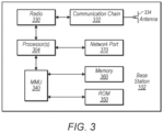
- FIG 3 illustrates an exemplary block diagram of a base station 102.
- base station 102 may be a broadcast base station such as base station 102A of Figure 2 and/or a cellular base station such as base station 102B of Figure 2 . It is noted that the base station of Figure 3 is merely one example of a possible base station.
- the base station 102 may include processor(s) 304 which may execute program instructions for the base station 102.
- the processor(s) 304 may also be coupled to memory management unit (MMU) 340, which may be configured to receive addresses from the processor(s) 304 and translate those addresses to locations in memory (e.g., memory 360 and read-only memory (ROM) 350) or to other circuits or devices.
- MMU memory management unit
- the base station 102 may include at least one network port 370.
- the network port 370 may be configured to couple to a telephone network and provide a plurality of devices, such as UE devices 106, access to the telephone network as described above.
- the network port 370 (or an additional network port) may be coupled to a television network and configured to receive content for broadcasting.
- the network port 370 (or an additional network port) may also or alternatively be configured to couple to a cellular network, e.g., a core network of a cellular service provider.
- the core network may provide mobility related services and/or other services to a plurality of devices, such as UE devices 106.
- the network port 370 may couple to a telephone network via the core network, and/or the core network may provide a telephone network (e.g., among other UE devices 106 serviced by the cellular service provider).
- the base station 102 may include at least one antenna 334.
- the at least one antenna 334 may be configured to operate as a wireless transceiver and may be further configured to communicate with UE devices 106 via radio 330.
- the antenna 334 communicates with the radio 330 via communication chain 332 in the illustrated embodiment.
- Communication chain 332 may be a receive chain, a transmit chain or both.
- the radio 330 may be configured to communicate via various RATs.
- the processor(s) 304 of the base station 102 may be configured to implement part or all of the methods described herein, e.g., by executing program instructions stored on a memory medium (e.g., a non-transitory computer-readable memory medium).
- the processor 304 may be configured as a programmable hardware element, such as an FPGA (Field Programmable Gate Array), or as an ASIC (Application Specific Integrated Circuit), or a combination thereof.
- the processor, MMU, and memory may be a distributed multiprocessor system.
- the processor system may comprise a plurality of interspersed processors and memories, where processing elements (also called functional units) are each connected to a plurality of memories, also referred to as data memory routers.
- the processor system may be programmed to implement the methods described herein.
- base station 102 is configured to perform both broadcast and bi-directional packet-switched communications.
- base station 102 may include multiple radios 330, communication chains 332, and/or antennas 334, for example.
- the disclosed spectrum sharing techniques may be performed by different base stations configured to perform only broadcast transmissions or only packet-switched communications.
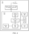
- FIG. 4 illustrates an example simplified block diagram of a UE 106.
- the UE 106 may be any of various devices as defined above.
- UE device 106 may include a housing which may be constructed from any of various materials.
- the UE 106 may include a system on chip (SOC) 400, which may include portions for various purposes.
- the SOC 400 may be coupled to various other circuits of the UE 106.
- the UE 106 may include various types of memory (e.g., including NAND flash 410), a connector interface 420 (e.g., for coupling to a computer system, dock, charging station, etc.), the display 460, wireless communication circuitry 430 such as for LTE, 5G New Radio (NR), GSM, Bluetooth (BT), WLAN, and/or broadcast, etc.
- the UE 106 may further comprise one or more smart cards that implement SIM (Subscriber Identity Module) functionality.
- the wireless communication circuitry 430 may couple to one or more antennas, such as antenna 435.
- the SOC 400 may include processor(s) 402 which may execute program instructions for the UE 106 and display circuitry 404 which may perform graphics processing and provide display signals to the display 460.
- the processor(s) 402 may also be coupled to memory management unit (MMU) 440, which may be configured to receive addresses from the processor(s) 402 and translate those addresses to locations in memory (e.g., memory (e.g., read only memory (ROM) or another type of memory) 406, NAND flash memory 410) and/or to other circuits or devices, such as the display circuitry 404, wireless communication circuitry 430, connector I/F 420, and/or display 460.
- the MMU 440 may be configured to perform memory protection and page table translation or set up.
- the MMU 440 may be included as a portion of the processor(s) 402.
- the processor, MMU, and memory may be a distributed multiprocessor system.
- the processor system may comprise a plurality of interspersed processors and memories, where processing elements (also called functional units) are each connected to a plurality of memories, also referred to as data memory routers.
- the processor system may be programmed to implement the methods described herein.
- UE 106 is configured to receive wireless broadcasts, e.g., from broadcast base station 102A of Figure 2 .
- UE 106 may include a broadcast radio receiver.
- UE 106 is configured to receive broadcast data and perform packet-switched cellular communications (e.g., LTE) at the same time using different frequency bands and/or the same frequency resources during different time slices. This may allow users to view TV broadcasts while performing other tasks such as browsing the internet (e.g., in a split-screen mode), using web applications, or listening to streaming audio.
- the disclosed techniques may be used in systems with devices that are configured as broadcast receivers or for cellular communications, but not both.
- the processor(s) 402 of the UE device 106 may be configured to implement part or all of the features described herein, e.g., by executing program instructions stored on a memory medium (e.g., a non-transitory computer-readable memory medium).
- the processor(s) 402 may comprise a multiprocessor array of a plurality of parallelized processing elements.
- the processor(s) 402 may be designed in accordance with the HyperX architecture described in detail in Reference 6, or another parallel processor architecture.
- separate ones of the parallelized processing elements may be configured to perform decoding procedures on separate respective bit paths of a successive cancellation list (SCL) decoding procedure, or they may be configured to perform decoding procedures on separate encoded messages in parallel, for example.
- SCL successive cancellation list
- processor(s) 402 may be configured as a programmable hardware element, such as an FPGA (Field Programmable Gate Array), or as an ASIC (Application Specific Integrated Circuit).
- processor(s) 402 of the UE device 106 in conjunction with one or more of the other components 400, 404, 406, 410, 420, 430, 435, 440, 460 may be configured to implement part or all of the features described herein.
- UE 106 may have a display 460, which may be a touch screen that incorporates capacitive touch electrodes. Display 460 may be based on any of various display technologies.
- the housing of the UE 106 may contain or comprise openings for any of various elements, such as buttons, speaker ports, and other elements (not shown), such as microphone, data port, and possibly various types of buttons, e.g., volume buttons, ringer button, etc.
- the UE 106 may support multiple radio access technologies (RATs).
- RATs radio access technologies
- UE 106 may be configured to communicate using any of various RATs such as two or more of Global System for Mobile Communications (GSM), Universal Mobile Telecommunications System (UMTS), Code Division Multiple Access (CDMA) (e.g., CDMA2000 1XRTT or other CDMA radio access technologies), Long Term Evolution (LTE), LTE Advanced (LTE-A), 5G NR, and/or other RATs.
- GSM Global System for Mobile Communications
- UMTS Universal Mobile Telecommunications System
- CDMA Code Division Multiple Access
- LTE Long Term Evolution
- LTE-A LTE Advanced
- 5G NR 5G NR
- the UE 106 may support at least two radio access technologies such as LTE and GSM.
- Various different or other RATs may be supported as desired.
- UE 106 is also configured to receive broadcast radio transmissions which may convey audio and/or video content.
- a UE 106 may be configured to receive broadcast radio transmissions and may not be configured to perform bi-directional communications with a base station (e.g., UE 106 may be a media playback device).
- a base station may broadcast a plurality of control messages (e.g., downlink control information (DCI) messages, or other encoded control information) that are each intended for reception by a specific user equipment device (UE).
- DCI downlink control information
- UE user equipment device
- FIG. 5 is a schematic diagram of various channels in downlink (DL) and uplink (UL) that are currently in use in some cellular communication technology standards (e.g., in LTE).
- DCI messages may be included in the physical downlink control channel (PDCCH), which may comprise a shared search space servicing a plurality of UEs.
- PDCCH physical downlink control channel
- Embodiments herein describe DCI messages that are typically sent over PDCCH.
- a base station transmits UE-specific messages that need to be disambiguated by a large number of serviced UEs (e.g., the physical broadcast channel, PBCH, may also be used to transmit this type of message, among other possibilities).
- a base station transmits UE-specific messages that need to be disambiguated by a large number of serviced UEs (e.g., the physical broadcast channel, PBCH, may also be used to transmit this type of message, among other possibilities).
- PBCH physical broadcast channel
- the base station may append a cyclic redundancy check (CRC) at the end of the control message.
- CRC cyclic redundancy check
- the base station may scramble a CRC that is attached to certain downlink control information (DCI) messages according to a user equipment identifier (UE ID).
- DCI downlink control information
- UE ID user equipment identifier
- the wrong UE e.g., a UE with a different UE ID than that used to scramble the CRC
- the UE with a matching UE ID may be able to correctly descramble the CRC and acknowledge the DCI message.
- the UE may assume that the message is destined for another user and drop the message.
- the receiver may otherwise use the known bit values just as it would a field of all zeros in decoding the surrounding information bits. Decoding may cease if a match to the intended recipient is not found using one of the methods described above. In other words, given the successive nature of polar decoding, the RX need not decode the entire packet to determine whether the check bits match its assigned ID.
- Embodiments herein expedite the blind detection procedure, as the base station may scramble the frozen bits of a polar code with a UE-specific mask to facilitate user identification.
- the information bits of the DCI may additionally be scrambled according to a cell-specific mask to mitigate adjacent cell interference.
- any transmitter/receiver pair may benefit from implementation of embodiments described herein, if the transmitter is attempting to transmit communications to a particular receiver, wherein there is a need for the receiver to verify both or either of: a) the identification of the transmitter and/or b) that the transmission was intended for the particular receiver.
- Embodiments herein describe a scrambling sequence design that builds on the objectives set forth by LTE and, leveraging attributes unique to polar codes, extends the design capabilities to include multi-mode block discrimination with the potential for early termination in a unified framework.
- separate masks are assigned to respective portions of the polar code construction, each with a distinct purpose: UE identification, early termination of blind decoding to minimize energy expended on blocks not intended for the present user, and/or adjacent cell interference mitigation. Early termination of blind decoding may advantageously reduce overall energy consumption for mobile devices.
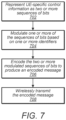
- Figure 7 illustrates a flow chart diagram for a method for modulating and encoding a message by a transmitter, according to some embodiments.
- separate scrambling masks may be applied to each of a plurality of different blocks within an encoded message.
- Each of the separate scrambling masks may serve to verify by the receiver an identity of either the transmitter or the receiver.
- both the transmitter and the receiver may be preconfigured with knowledge of the transmitter and/or receiver identities, such that the receiver may be able to selectively demask respective blocks of the scrambled message.
- the transmitter may be a base station and the receiver may be a user equipment device (UE). Alternatively, both the transmitter and receiver may be UEs.
- UE user equipment device
- Polar coding divides (or 'polarizes') a plurality of communication channels into more reliable and less reliable channels.
- the more reliable channels are often used to carry the payload information of the communication, and these bits of the communication are often referred to as 'information bits'.
- the transmitter may append a sequence of cyclic redundancy check (CRC) bits at the end of the information bits.
- CRC cyclic redundancy check
- the less reliable channels typically contain reference bits that are known to both the transmitter and the receiver, commonly referred to as 'frozen bits'.
- the frozen bits may be utilized by the receiver to facilitate the decoding process.
- modulating the one or more of the sequences of bits based on the one or more identifiers may involve applying separate scrambling 'masks' to modulate the sequences of bits based on the identifier(s).
- the application of a scrambling mask may involve modulating each sequence of bits with a PRS of bits generated from a respective identifier.
- a UE ID corresponding to the intended receiver may be used to generate a first pseudorandom sequence PRS that is the same length as the length of a frozen bit sequence in a polar code.
- the first PRS may be used to modulate the frozen bits of the polar code.
- the first PRS may be the same length as a subset of frozen bits, and may be used to modulate only the subset of frozen bits.
- a subset of the frozen bits may be directly modulated by the UE ID.
- the UE ID may be used to modulate the frozen bits while not modulating the information bits.
- the UE ID may be used to selectively modulate only the frozen bits, and not the information bits, of the control information.
- a CELL ID of the transmitter may be used to generate a second PRS that is the same length as the length of the information bit sequence of a polar code.
- the second PRS may be used to modulate the information bits of the polar code.
- modulating the information bit sequence based on the pseudorandom sequence generated from the base station identifier may mitigate adjacent cell interference experienced by UEs that receive the encoded modulated control information.
- a first UE may be located in a service area of two or more base stations, and a UE ID used for the first UE by a first base station (e.g., a base station upon which the first UE is camped) may additionally be used as a UE ID for another (second) UE by a second base station (e.g., a base station upon which the first UE may receive broadcast messages but is not camped).
- the first UE may mistake a message intended for the second UE as intended for the first UE (e.g., because the same UE ID is used for both).
- modulating the information bit sequence based on a base station identifier may allow the first UE to determine whether a particular message has originated from the correct base station (e.g., the base station upon which the first UE is camped).
- a UE ID corresponding to the intended receiver may be used to generate a third PRS that is the same length as the CRC bits that are appended to a polar coded message.
- the third PRS may be used to modulate the CRC mask, such that the CRC mask is generated based on the UE ID.
- the information bits may be appended with a cyclic redundancy check (CRC) scrambled with a CRC mask based on the UE ID, which may be performed prior to modulating the information bits. This may offer an additional check by the receiver that the receiver is the intended recipient of the message.
- CRC cyclic redundancy check
- the two or more sequences of bits may be encoded to produce an encoded message.
- the modulated frozen bits, information bits, and/or CRC bits may be encoded using polar codes to produce encoded modulated control information, which may comprise the encoded message.
- the encoded modulated control information may be transmitted to one or more UEs for performing downlink control information (DCI) blind detection.
- DCI downlink control information
- the transmitter may transmit the encoded message to the receiver (e.g., in a wireless manner).
- the transmission may occur using any of a variety of wireless communication technologies, as described variously in the present disclosure.
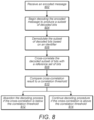
- FIG 8 is a flow chart diagram illustrating a method for decoding and demodulating an encoded message (e.g., coded data, or polar coded data received from a remote transmitter) by a receiver, according to some embodiments.
- the receiver may be a user equipment device (UE) comprising a radio, a non-transitory computer-readable memory medium, and a processor (e.g., as described above in reference to Figure 4 ), or it may be another kind of receiver.
- UE user equipment device
- a processor e.g., as described above in reference to Figure 4
- the receiver may receive the encoded message from a transmitter in a wireless manner.
- the encoded message may comprise coded data including an encoding of one or more sequences of bits (e.g., a first sequence of bits and potentially a second and third sequence of bits).
- the receiver may have knowledge of each of the identifiers used by the transmitter to modulate respective subsets of bits of the encoded message.
- the encoded message may be a polar coded message, and the one or more sequences of bits may include a sequence of frozen bits, a sequence of information bits, and/or a sequence of cyclic redundancy check (CRC) bits.
- the encoded message may be received and decoded (e.g., as described in detail below) as part of a downlink control information (DCI) blind detection procedure.
- DCI downlink control information
- the receiver may proceed to implement a decoding procedure on the coded data, as described in further detail below in reference to steps 804-814.
- the decoding procedure may be a successive cancellation list decoding procedure, or any of a variety of other decoding procedures.
- the receiver may begin a decode of the encoded message to produce a subset of the first sequence of bits.
- the first sequence of bits may be frozen bits of a polar code, so that the decoding procedure begins by decoding a subset of the frozen bits, for example.
- the cross-correlation may be performed after demodulating using the PRS, but in other embodiments the sequence of reference bits may be based on the first identifier, and the demodulation step 806 may be skipped.
- the cross-correlation may be performed with reference bits that are generated based on the first identifier, so that the demodulation is implicitly accomplished through the cross-correlation calculation.
- the PRS may be the same length as the entire frozen bit field, but the demodulation may be performed using the subset of the PRS that corresponds to the decoded subset of frozen bits.
- the receiver may demodulate the second sequence of bits with a second pseudorandom sequence generated from a second identifier.
- the second sequence of bits are information bits of a polar code
- the information bits may have been scrambled using a second PRS generated from an identifier unique to the transmitter (e.g., a base station ID).
- the receiver may demodulate (e.g., unscramble) the decoded information bits using the same second PRS.
- the receiver may then store the demodulated second sequence of bits as a decoded message in the memory medium.
- SCL successive cancellation list
- a method of constructing capacity achieving codes for the memoryless binary symmetric channel is known in the art.
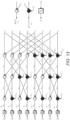
- the resulting polar codes leverage a phenomenon known as channel polarization (see Figure 11 ) resulting from a recursive process by which the channel capacity, i.e. maximum mutual information, tends toward 1 (fully available) or 0 (unavailable).
- the corresponding bit probabilities, 1 and 0.5, respectively, approach their limits as the code length, N 2 n , increases with positive integer values n.
- Data may be transferred by placing information on bits on the most reliable channels (these bits may be referred to as information bits) while bits placed on the least reliable channels may be set to a fixed value, e.g.
- frozen bits Frozen bits and their mapping to the code matrix may be known by both the transmitter and receiver. As a result, frozen bits may be used as a reference by a decoding algorithm to determine whether an error has occurred from noise in the communication channel, or otherwise. For example, the known values of the frozen bits may be compared to the values determined through the decoding algorithm, to determine whether an error has occurred.
- the decoder may pursue multiple paths in parallel, retaining the most likely paths at each stage.
- the encoder may also append a cyclic redundancy check (CRC) that is ultimately used in determining the appropriate bit decision from the available L paths, see Balatsoukas-Stimming et al. in reference 2 above.
- CRC cyclic redundancy check
- any of the decoding processes described herein may be implemented according to a SCL decoding methodology. Additionally, a concatenated SCL decoding methodology may be employed.
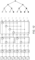
- Polar codes form a class of linear block codes described by a generator matrix, G.
- a polar code is defined by the location of k information bits and (N-k) frozen bits in a block of length, N .
- the code rate can be adjusted linearly by varying the number of non-frozen bits per block.
- the encoder begins with inputs, u i , which are encoded into outputs, x i . Information bits are shown in bold. The remaining inputs may be assigned frozen bit values, 0.
- the encoder combines pairs of bits according to the encoding tree shown to the right, where ⁇ indicates an exclusive-OR (XOR) operation.
- the SCL decoder may be viewed as a collection of SC decoders, each employing independent min-sum calculations on a row of the accumulated log likelihood ratio (LLR) statistics.
- an SC decoder may proceed as follows:
- LLR log likelihood ratio
- the decoder algorithm is applied recursively to the multi-stage diagram illustrated in Figure 13 according to the following: ⁇ l , i ⁇ ⁇ f ⁇ l + 1 , i ⁇ l + 1 , i + 2 n ⁇ l ⁇ 1 , if i 2 l is even ⁇ g s ⁇ l , z ⁇ l + 1 , i ⁇ l + 1 , i + 2 n ⁇ l ⁇ 1 , otherwise
- ⁇ l,i denotes the LLR of row i and stage l of the SC decoder graph.
- the SCL decoders described in reference 2 above use the results of the sorting operation to direct multiple memory copies ( memcpy ), adding processing overhead as the LLR updates cannot resume until the memcpy operations have completed.
- user identification is based on an assigned C-RNTI (Cell Radio Network Temporary Identifier).
- C-RNTI Cell Radio Network Temporary Identifier
- cell-specific scrambling is used to mitigate the effects of adjacent cell interference.
- methods described herein may function at signal-to-noise ratios (SNRs) below that for the accompanying shared data channels. Additionally, some embodiments may reduce the false alarm rate (FAR) compared to previous implementations.
- SNRs signal-to-noise ratios
- FAR false alarm rate
- LTE defines a set of Control Channel Element (CCE) locations for a UE to interrogate in search of intended Physical Downlink Control Channel (PDCCH) communications.
- the set of CCE locations are divided into UE Specific Search Spaces (UESS) and Common Search Spaces (CSS) as indicated in Table 1.
- Table 1 LTE DCI Search Spaces Search Space Aggregation Level (L) Size (in CCEs) No. of PDCCH Candidates No. of Candidate Blind Decodes UESS 1 6 6 12 2 12 6 12 4 8 2 4 8 16 2 4 UESS: 16 32 CSS 4 16 4 8 8 16 2 4 CSS: 6 12 Total: 44
- each UE may receive up to 2 DCI formats from UESS per Transmission Time Interval (TTI).
- TTI Transmission Time Interval
- One reference DCI format e.g. format 0/1A
- the reference DCI formats may require a single decoding attempt per candidate location regardless of the underlying format type.
- Each UE may require one additional decoding attempt per UESS candidate location for one of DCI formats 1, 1B, 1D, 2, 2A, 2B, depending upon the configured transmission mode, every TTI.
- DCI formats 0/1A and 3/3A may require one blind decoding attempt per candidate PDCCH location in the CSS.
- SI-RNTI System Information
- P-RNTI Paging
- RA-RNTI Random Access
- Figure 14 illustrates DCI encoding as prescribed for LTE.
- LTE employs two methods of block discrimination on DCI detection as depicted in Figure 14 , which as explained in further detail below (e.g., in reference to Figure 15 ), may be superimposed on the polar code structure.
- Figure 14 illustrates a tail-biting convolutional encoder, which may be replaced by a polar code methodology for block discrimination, according to some embodiments.
- embodiments described herein perform a multi-mode discrimination mask that can be adapted to a downlink control channel.
- a 16-bit CRC may be appended to each PDCCH for error detection.
- the CRC may be scrambled with a UE-specific mask to enable identification of which PDCCH(s) are intended for a given UE upon interrogating the list of candidate PDCCH locations.
- the information bits may be masked with a cell-specific mask (CELL ID mask) to mitigate the effects of adjacent-cell interference.
- a cell-specific mask CELL ID mask
- Figure 15 illustrates DCI adapted to incorporate polar codes (potentially in NR), according to some embodiments.
- Figure 15 illustrates the separate application of bit masks to each of frozen bits, information bits, and CRC bits, respectively, in a polar coded message. As illustrated, the multi-mode mask assignment separately uses different subsets of the bit field for separate identification purposes.
- (+) represents a bit-wise XOR of the resulting scrambling mask, wG , computed once per DCI instance, with the original encoder output, uG.
- the bit masks, s 0:F-1 , r 0:D-1 , x rnti,0:15 , applied in succession at the encoder input as illustrated in Figure 16 are equivalent to the scrambling mask, wG , applied at the encoder output, where 0 0:M-1 represents an all zero vector of length M , and G relates a scrambling mask, w , at the encoder input to the encoder output.
- the combined mask can be similarly removed at the receiver prior to decoding.
- Properties assigned to a mask at the encoder input manifest equivalently in a corresponding mask applied at the encoder output. Individual attributes can be assigned so that each mask produces an intended effect as referenced to the construction at the encoder input. The mask contributions may then be combined, encoded, and then applied at the encoder output without loss in effectiveness.
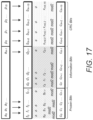
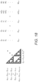
- Figures 17-18 illustrate bit-mask assignment patterned after that used by LTE, according to some embodiments.
- pseudorandom sequence generation is adapted for a variety of purposes (See reference 3).
- An exemplary method for generating a pseudorandom sequence is illustrated here to indicate that this method or one similar can be applied to fill the frozen bit contents, the initialization of which is based on the representation of the UE ID.
- the method of pseudorandom sequence generation specified by LTE may be adapted to form the frozen bit contents initialized by C-RNTI to facilitate early discrimination with DCI blind detection.
- a second application may form the information bit mask initialized on the CELL ID.
- c n x n + N c 1 + x n + N c 2 mod 2
- n 0 , 1 , ... , M PN ⁇ 1
- Extending the pseudorandom sequence length to the number of available frozen bits provides early user separation in a deterministic and reliable manner. If the entirety of the frozen bit contents are populated with the UE ID-derived pseudorandom sequence, a reliable and efficient means of early block discrimination may be obtained. Similarly, a pseudorandom sequence may be derived from the CELL ID and applied as a bit mask to the information portion of the block. Additionally or alternatively, the CRC may be masked based on the assigned RNTI as is done in LTE. After applying the appropriate zero padding and then summing the masks, their combined effect may be applied in a single scrambling sequence at the encoder output.
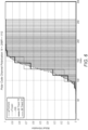
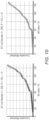
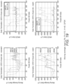
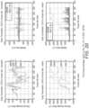
- Figure 19 illustrates data for an early termination procedure of frozen bit decoding, for the case of both a match and a mismatch between the encoding and decoding UE ID.
- a moving average of the best LLRs exhibits an increasing trend upon match in frozen bit assignment and trends downward when there is a mismatch in expected bit assignment.
- the top two plots correspond to a mismatch in frozen bit assignment between encoder and decoder.
- the accumulated LLRs exhibit a sharp downward trend as the number of negative matches begins to accumulate. The onset of this downturn is a function of the length of the applied moving average. It occurs earlier with a shorter moving average and later with a longer moving average.
- the downstream LLRs may be affected as well in a manner that is incremental to disturbance due to the channel itself.
- the data in Figure 20 is taken at relatively high SNR, and as illustrated the LLRs in the bottom right-hand plot predominantly trend in the positive direction whereas those in the upper right-hand plot show the disruptive effects of the channel coupled with erroneous feedback in the g-operator.
- Erroneous feedback in the g-operator propagates to downstream bit decoding, frozen and info-bits alike, further reducing FAR should an unintended PDCCH elude early termination and make its way to a final CRC check.
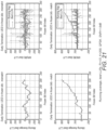
- the effects of frozen bit mismatch persist even in the event that the scrambling mask is removed prior to the start of decoding.
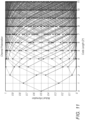
- Figure 21 illustrates how the combined effects of sequence mismatch and error propagation due to g-operator feedback give rise to heuristics that may prove useful for early block discrimination.
- the moving average of the best LLR for a UE ID mismatch (top) oscillates between positive and negative values without exhibiting a clear positive trend, while the moving average of the best LLR for a UE ID match (bottom) steadily climbs as a function of the frozen bit index.
- Embodiments herein describe a method of frozen bit assignment that may be used in polar code construction to facilitate early block discrimination on DCI blind detection.
- the proposal leverages a property unique to polar codes that permits use of frozen bit contents to convey user ID, and/or information bit contents to convey CELL ID.
- the structure is further leveraged to provide cell separation in a manner that meets the objectives set for LTE.
- the end result is a scrambling sequence that enables both CELL ID and UE ID with the added benefit of early termination. Replicated at the decoder, this imprinting is useful in discerning blocks intended for a particular receiver amid multiple candidate PDCCHs, most of which are destined by design for some other user.
- the reliability of block determination improves as a function of bit position in accordance with the underlying channel reliability.
- the approach is compatible with PC, CRC or hybrid methods of code construction still under consideration.
- the proposed method of embedding UE ID imposes minimal changes in presumed encoder and decoder implementations. It further provides wide latitude in algorithm design, permitting receiver manufacturers to trade power savings for reliability of early termination.
- Embodiments of the present disclosure may be realized in any of various forms.
- the present invention may be realized as a computer-implemented method, a computer-readable memory medium, or a computer system.
- the present invention may be realized using one or more custom-designed hardware devices such as ASICs.
- the present invention may be realized using one or more programmable hardware elements such as FPGAs.
- a non-transitory computer-readable memory medium may be configured so that it stores program instructions and/or data, where the program instructions, if executed by a computer system, cause the computer system to perform a method, e.g., any of the method embodiments described herein, or, any combination of the method embodiments described herein, or, any subset of any of the method embodiments described herein, or, any combination of such subsets.
- a computing device may be configured to include a processor (or a set of processors) and a memory medium, where the memory medium stores program instructions, where the processor is configured to read and execute the program instructions from the memory medium, where the program instructions are executable to implement any of the various method embodiments described herein (or, any combination of the method embodiments described herein, or, any subset of any of the method embodiments described herein, or, any combination of such subsets).
- the device may be realized in any of various forms.
Landscapes
- Engineering & Computer Science (AREA)
- Computer Networks & Wireless Communication (AREA)
- Signal Processing (AREA)
- Physics & Mathematics (AREA)
- Spectroscopy & Molecular Physics (AREA)
- Power Engineering (AREA)
- Probability & Statistics with Applications (AREA)
- Theoretical Computer Science (AREA)
- Mobile Radio Communication Systems (AREA)
- Error Detection And Correction (AREA)
- Detection And Prevention Of Errors In Transmission (AREA)
Applications Claiming Priority (6)
| Application Number | Priority Date | Filing Date | Title |
|---|---|---|---|
| US201762442225P | 2017-01-04 | 2017-01-04 | |
| US201762455448P | 2017-02-06 | 2017-02-06 | |
| US201762501493P | 2017-05-04 | 2017-05-04 | |
| US201762521946P | 2017-06-19 | 2017-06-19 | |
| US15/852,632 US10327235B2 (en) | 2017-01-04 | 2017-12-22 | Scrambling sequence design for multi-mode block discrimination on DCI blind detection |
| PCT/US2017/068972 WO2018128928A1 (en) | 2017-01-04 | 2017-12-29 | Scrambling sequence design for multi-mode block discrimination on dci blind detection |
Publications (3)
| Publication Number | Publication Date |
|---|---|
| EP3566345A1 EP3566345A1 (en) | 2019-11-13 |
| EP3566345C0 EP3566345C0 (en) | 2025-07-09 |
| EP3566345B1 true EP3566345B1 (en) | 2025-07-09 |
Family
ID=62711608
Family Applications (2)
| Application Number | Title | Priority Date | Filing Date |
|---|---|---|---|
| EP17833076.7A Active EP3566345B1 (en) | 2017-01-04 | 2017-12-29 | Scrambling sequence design for multi-mode block discrimination on dci blind detection |
| EP17835566.5A Pending EP3566346A1 (en) | 2017-01-04 | 2017-12-29 | Scrambling sequence design for embedding ue id into frozen bits for dci blind detection |
Family Applications After (1)
| Application Number | Title | Priority Date | Filing Date |
|---|---|---|---|
| EP17835566.5A Pending EP3566346A1 (en) | 2017-01-04 | 2017-12-29 | Scrambling sequence design for embedding ue id into frozen bits for dci blind detection |
Country Status (5)
| Country | Link |
|---|---|
| US (5) | US10383106B2 (enExample) |
| EP (2) | EP3566345B1 (enExample) |
| JP (2) | JP7132222B2 (enExample) |
| CN (2) | CN110463093B (enExample) |
| WO (2) | WO2018128928A1 (enExample) |
Families Citing this family (31)
| Publication number | Priority date | Publication date | Assignee | Title |
|---|---|---|---|---|
| CN103220001B (zh) * | 2012-01-20 | 2016-09-07 | 华为技术有限公司 | 与循环冗余校验级联的极性码的译码方法和译码装置 |
| US10461887B2 (en) * | 2016-08-10 | 2019-10-29 | Huawei Technologies Co., Ltd. | Methods and systems for blind detection with polar code |
| US10383106B2 (en) | 2017-01-04 | 2019-08-13 | Coherent Logix, Incorporated | Scrambling sequence design for embedding UE ID into frozen bits for DCI blind detection |
| WO2018126378A1 (en) * | 2017-01-05 | 2018-07-12 | Qualcomm Incorporated | Wireless communication with polar codes using a mask sequence for frozen bits |
| US10348328B2 (en) | 2017-01-06 | 2019-07-09 | At&T Intellectual Property I, L.P. | Reducing control channel overhead using polar codes |
| EP3566344B1 (en) * | 2017-01-09 | 2020-10-07 | Telefonaktiebolaget LM Ericsson (PUBL) | Coding technique for multi-stage control information |
| CN108347296B (zh) * | 2017-01-25 | 2020-12-22 | 华为技术有限公司 | 一种信息传输方法及设备 |
| JPWO2018143124A1 (ja) * | 2017-01-31 | 2019-11-21 | 株式会社Nttドコモ | 通信装置、及び系列選択方法 |
| WO2018170834A1 (en) | 2017-03-23 | 2018-09-27 | Qualcomm Incorporated | Parity bit channel assignment for polar coding |
| CN108631923B (zh) * | 2017-03-24 | 2020-11-17 | 华为技术有限公司 | 传输信息的方法、网络设备和终端设备 |
| CN108683479B (zh) * | 2017-03-25 | 2019-08-13 | 华为技术有限公司 | 一种速率匹配的方法和装置 |
| US10742238B2 (en) * | 2017-05-05 | 2020-08-11 | Qualcomm Incorporated | Frozen bits based pruning and early termination for polar decoding |
| US10868569B2 (en) * | 2017-05-08 | 2020-12-15 | Qualcomm Incorporated | PBCH signal design and efficient continuous monitoring and polar decoding |
| EP3622646B1 (en) * | 2017-05-08 | 2020-10-21 | Coherent Logix, Inc. | Enhanced polarization weighting to enable scalability in polar code bit distribution |
| US10348336B2 (en) * | 2017-06-06 | 2019-07-09 | Tsofun Algorithm Ltd. | System and method for early termination of decoding in a multi user equipment environment |
| US10560910B2 (en) | 2017-06-12 | 2020-02-11 | Qualcomm Incoporated | Synchronization signal for a broadcast channel |
| FI3644679T3 (fi) * | 2017-06-20 | 2025-12-03 | Beijing Xiaomi Mobile Software Co Ltd | Menetelmä ja laite aikataulutussignaloinnin havaitsemiseksi |
| JP7345471B2 (ja) * | 2017-08-11 | 2023-09-15 | コーヒレント・ロジックス・インコーポレーテッド | Dciブラインド検出時のマルチモード・ブロック弁別のためのスクランブル系列設計 |
| US11101910B2 (en) * | 2018-01-12 | 2021-08-24 | Qualcomm Incorporated | Sequence based short code design for resource spread multiple access (RSMA) |
| US10608669B2 (en) * | 2018-02-16 | 2020-03-31 | At&T Intellectual Property I, L.P. | Performance of data channel using polar codes for a wireless communication system |
| EP3570442A1 (en) * | 2018-05-17 | 2019-11-20 | Industrial Technology Research Institute | Compact transmission of polar encoded dci with repetition for 5g communication systems |
| CN109286473B (zh) * | 2018-11-16 | 2020-06-19 | 北京航空航天大学 | 一种基于极化码的低复杂度pdcch信道盲检测方法 |
| KR20200084687A (ko) * | 2019-01-03 | 2020-07-13 | 삼성전자주식회사 | 비이진 폴라 코드를 수신하는 장치 및 이의 디코딩 방법 |
| US12232145B2 (en) * | 2019-12-23 | 2025-02-18 | Qualcomm Incorporated | PDCCH monitoring reduction for reduced-capability user equipments |
| US11451330B2 (en) | 2020-05-05 | 2022-09-20 | Viavi Solutions Inc. | Method for reducing false detection of successful decoding of cyclic redundancy check codes |
| US20240063978A1 (en) * | 2020-09-22 | 2024-02-22 | Toyota Jidosha Kabushiki Kaisha | System and method for efficient utilization of padding bits |
| US20240146454A1 (en) * | 2021-04-01 | 2024-05-02 | Intel Corporation | Enhanced mapping for control channel transmission based on polar code |
| CN113644958A (zh) * | 2021-07-15 | 2021-11-12 | 南京熊猫汉达科技有限公司 | 一种低轨卫星窄带通信系统及同频干扰规避方法 |
| US20240292428A1 (en) * | 2023-02-16 | 2024-08-29 | Viavi Solutions Inc. | Decoding downlink control information received via a downlink control channel |
| KR102757663B1 (ko) * | 2023-06-20 | 2025-01-21 | 아주대학교산학협력단 | 파워 게이팅을 이용한 극 부호의 연속 제거 목록 복호화 장치 및 방법 |
| US20250167917A1 (en) * | 2023-11-22 | 2025-05-22 | Qualcomm Incorporated | Polar code scheme selection based on receiver decoding capability |
Citations (1)
| Publication number | Priority date | Publication date | Assignee | Title |
|---|---|---|---|---|
| EP3688908A1 (en) * | 2017-08-11 | 2020-08-05 | Coherent Logix, Inc. | Scrambling sequence design for multi-mode block discrimination on dci blind detection |
Family Cites Families (24)
| Publication number | Priority date | Publication date | Assignee | Title |
|---|---|---|---|---|
| US8478258B2 (en) * | 2010-03-05 | 2013-07-02 | Intel Corporation | Techniques to reduce false detection of control channel messages in a wireless network |
| CN115767752A (zh) * | 2011-02-11 | 2023-03-07 | 交互数字专利控股公司 | 用于增强型控制信道的系统和方法 |
| US8989121B2 (en) * | 2011-11-02 | 2015-03-24 | Qualcomm Incorporated | Blindly decoding interfering cell PDCCH to acquire interfering cell PDSCH transmission information |
| US9402251B2 (en) | 2012-08-03 | 2016-07-26 | Intel Corporation | Enhanced physical downlink control channel scrambling and demodulation reference signal sequence generation |
| WO2014116301A1 (en) | 2013-01-24 | 2014-07-31 | California Institute Of Technology | Joint rewriting and error correction in write-once memories |
| USRE49547E1 (en) * | 2013-08-20 | 2023-06-06 | Lg Electronics Inc. | Method for transmitting data by using polar coding in wireless access system |
| US9673957B2 (en) * | 2013-09-19 | 2017-06-06 | Telefonaktiebolaget Lm Ericsson (Publ) | System and method for providing interference characteristics for interference mitigation |
| EP3073660B1 (en) * | 2013-11-20 | 2020-06-24 | Huawei Technologies Co., Ltd. | Polar code processing method and device |
| BR112016014679B1 (pt) * | 2013-12-24 | 2021-11-03 | Huawei Technologies Co., Ltd | Método de decodificação de código polar e aparelho de decodificação |
| BR112016021434A2 (pt) * | 2014-03-19 | 2017-08-15 | Huawei Tech Co Ltd | Método de equiparação de taxa de código polar e aparelho de equiparação de taxa |
| US10411828B2 (en) * | 2014-03-20 | 2019-09-10 | Intel IP Corporation | Methods, systems, and devices for modulation and coding scheme signaling for common control channel |
| CA2972655C (en) * | 2014-03-24 | 2020-10-20 | Huawei Technologies Co., Ltd. | Polar code rate matching method and polar code rate matching apparatus |
| EP3002897B1 (en) * | 2014-09-30 | 2017-07-19 | Telefonica S.A. | Method and system for assisting user devices in performing interference cancellation in ofdma wireless communication networks |
| JP6377184B2 (ja) | 2015-02-09 | 2018-08-22 | 三菱電機株式会社 | 通信装置 |
| CN104918063A (zh) * | 2015-06-01 | 2015-09-16 | 中国农业大学 | 一种基于Polar码技术的可抗差错图像传输方法 |
| TW201733322A (zh) * | 2015-12-14 | 2017-09-16 | Idac控股公司 | 使用極化碼凍結位元之wtru識別 |
| EP3364542A4 (en) | 2015-12-23 | 2019-04-03 | Huazhong University of Science and Technology | ERROR CORRECTION CODING PROCEDURES BASED ON THE CASCADING OF POLAR CODES AND REPEAT CODES OR MULTIBIT PARITY CHECK CODES |
| US10312947B2 (en) * | 2016-01-21 | 2019-06-04 | Huawei Technologies Co., Ltd. | Concatenated and sliding-window polar coding |
| WO2017186307A1 (en) * | 2016-04-29 | 2017-11-02 | Telefonaktiebolaget Lm Ericsson (Publ) | Polar code successive cancellation list decoding |
| US10579452B2 (en) | 2016-06-17 | 2020-03-03 | Huawei Technologies Co., Ltd. | Systems and methods for rate matching via a heterogeneous kernel when using general polar codes |
| US10461887B2 (en) | 2016-08-10 | 2019-10-29 | Huawei Technologies Co., Ltd. | Methods and systems for blind detection with polar code |
| CN114884610B (zh) | 2016-08-11 | 2024-04-09 | 华为技术有限公司 | 用于极化编码的方法、装置和设备 |
| US10383106B2 (en) * | 2017-01-04 | 2019-08-13 | Coherent Logix, Incorporated | Scrambling sequence design for embedding UE ID into frozen bits for DCI blind detection |
| US10440703B2 (en) | 2017-01-10 | 2019-10-08 | Mediatek Inc. | Physical downlink control channel design for 5G new radio |
-
2017
- 2017-12-22 US US15/852,761 patent/US10383106B2/en active Active
- 2017-12-22 US US15/852,632 patent/US10327235B2/en active Active
- 2017-12-29 EP EP17833076.7A patent/EP3566345B1/en active Active
- 2017-12-29 CN CN201780086069.2A patent/CN110463093B/zh active Active
- 2017-12-29 CN CN201780085964.2A patent/CN110495113B/zh active Active
- 2017-12-29 WO PCT/US2017/068972 patent/WO2018128928A1/en not_active Ceased
- 2017-12-29 JP JP2019536263A patent/JP7132222B2/ja active Active
- 2017-12-29 JP JP2019536298A patent/JP7364466B2/ja active Active
- 2017-12-29 WO PCT/US2017/069014 patent/WO2018128932A1/en not_active Ceased
- 2017-12-29 EP EP17835566.5A patent/EP3566346A1/en active Pending
-
2019
- 2019-07-01 US US16/459,072 patent/US10560932B2/en active Active
-
2020
- 2020-02-10 US US16/786,332 patent/US10887879B2/en active Active
-
2021
- 2021-01-04 US US17/140,688 patent/US11350404B2/en active Active
Patent Citations (1)
| Publication number | Priority date | Publication date | Assignee | Title |
|---|---|---|---|---|
| EP3688908A1 (en) * | 2017-08-11 | 2020-08-05 | Coherent Logix, Inc. | Scrambling sequence design for multi-mode block discrimination on dci blind detection |
Also Published As
| Publication number | Publication date |
|---|---|
| EP3566345A1 (en) | 2019-11-13 |
| US20200196286A1 (en) | 2020-06-18 |
| CN110495113B (zh) | 2022-07-19 |
| CN110463093A (zh) | 2019-11-15 |
| EP3566346A1 (en) | 2019-11-13 |
| JP2020504527A (ja) | 2020-02-06 |
| EP3566345C0 (en) | 2025-07-09 |
| JP2020504525A (ja) | 2020-02-06 |
| US10383106B2 (en) | 2019-08-13 |
| US10327235B2 (en) | 2019-06-18 |
| US20180192402A1 (en) | 2018-07-05 |
| US10560932B2 (en) | 2020-02-11 |
| US20180192403A1 (en) | 2018-07-05 |
| JP7132222B2 (ja) | 2022-09-06 |
| CN110495113A (zh) | 2019-11-22 |
| US11350404B2 (en) | 2022-05-31 |
| JP7364466B2 (ja) | 2023-10-18 |
| US20210219272A1 (en) | 2021-07-15 |
| US20190327722A1 (en) | 2019-10-24 |
| WO2018128928A1 (en) | 2018-07-12 |
| CN110463093B (zh) | 2022-05-17 |
| US10887879B2 (en) | 2021-01-05 |
| WO2018128932A1 (en) | 2018-07-12 |
Similar Documents
| Publication | Publication Date | Title |
|---|---|---|
| US11350404B2 (en) | Scrambling sequence design for embedding receiver ID into frozen bits for blind detection | |
| US11405245B2 (en) | Scrambling sequence design for multi-mode block discrimination on DCI blind detection | |
| US11211947B2 (en) | Polar code encoding method and apparatus, polar code decoding method and apparatus, and device | |
| US10749633B2 (en) | Generation of polar codes with a variable block length utilizing | |
| CN110574292B (zh) | 针对极性解码的基于冻结比特的路径修剪和提早终止 | |
| CN110622427B (zh) | 连续消除列表解码的提前终止 | |
| US10567008B2 (en) | Stopping criteria for turbo decoder | |
| US20200187166A1 (en) | Sub-channel mapping |
Legal Events
| Date | Code | Title | Description |
|---|---|---|---|
| STAA | Information on the status of an ep patent application or granted ep patent |
Free format text: STATUS: UNKNOWN |
|
| STAA | Information on the status of an ep patent application or granted ep patent |
Free format text: STATUS: THE INTERNATIONAL PUBLICATION HAS BEEN MADE |
|
| PUAI | Public reference made under article 153(3) epc to a published international application that has entered the european phase |
Free format text: ORIGINAL CODE: 0009012 |
|
| STAA | Information on the status of an ep patent application or granted ep patent |
Free format text: STATUS: REQUEST FOR EXAMINATION WAS MADE |
|
| 17P | Request for examination filed |
Effective date: 20190730 |
|
| AK | Designated contracting states |
Kind code of ref document: A1 Designated state(s): AL AT BE BG CH CY CZ DE DK EE ES FI FR GB GR HR HU IE IS IT LI LT LU LV MC MK MT NL NO PL PT RO RS SE SI SK SM TR |
|
| AX | Request for extension of the european patent |
Extension state: BA ME |
|
| DAV | Request for validation of the european patent (deleted) | ||
| DAX | Request for extension of the european patent (deleted) | ||
| STAA | Information on the status of an ep patent application or granted ep patent |
Free format text: STATUS: EXAMINATION IS IN PROGRESS |
|
| 17Q | First examination report despatched |
Effective date: 20210319 |
|
| GRAP | Despatch of communication of intention to grant a patent |
Free format text: ORIGINAL CODE: EPIDOSNIGR1 |
|
| STAA | Information on the status of an ep patent application or granted ep patent |
Free format text: STATUS: GRANT OF PATENT IS INTENDED |
|
| INTG | Intention to grant announced |
Effective date: 20241014 |
|
| GRAS | Grant fee paid |
Free format text: ORIGINAL CODE: EPIDOSNIGR3 |
|
| GRAA | (expected) grant |
Free format text: ORIGINAL CODE: 0009210 |
|
| STAA | Information on the status of an ep patent application or granted ep patent |
Free format text: STATUS: THE PATENT HAS BEEN GRANTED |
|
| AK | Designated contracting states |
Kind code of ref document: B1 Designated state(s): AL AT BE BG CH CY CZ DE DK EE ES FI FR GB GR HR HU IE IS IT LI LT LU LV MC MK MT NL NO PL PT RO RS SE SI SK SM TR |
|
| REG | Reference to a national code |
Ref country code: GB Ref legal event code: FG4D |
|
| REG | Reference to a national code |
Ref country code: CH Ref legal event code: EP |
|
| REG | Reference to a national code |
Ref country code: IE Ref legal event code: FG4D |
|
| REG | Reference to a national code |
Ref country code: DE Ref legal event code: R096 Ref document number: 602017090495 Country of ref document: DE |
|
| U01 | Request for unitary effect filed |
Effective date: 20250724 |
|
| U07 | Unitary effect registered |
Designated state(s): AT BE BG DE DK EE FI FR IT LT LU LV MT NL PT RO SE SI Effective date: 20250902 |
|
| REG | Reference to a national code |
Ref country code: GB Ref legal event code: 732E Free format text: REGISTERED BETWEEN 20251120 AND 20251126 |
|
| REG | Reference to a national code |
Ref country code: CH Ref legal event code: W10 Free format text: ST27 STATUS EVENT CODE: U-0-0-W10-W00 (AS PROVIDED BY THE NATIONAL OFFICE) Effective date: 20251224 |
|
| PG25 | Lapsed in a contracting state [announced via postgrant information from national office to epo] |
Ref country code: IS Free format text: LAPSE BECAUSE OF FAILURE TO SUBMIT A TRANSLATION OF THE DESCRIPTION OR TO PAY THE FEE WITHIN THE PRESCRIBED TIME-LIMIT Effective date: 20251109 |
|
| PGFP | Annual fee paid to national office [announced via postgrant information from national office to epo] |
Ref country code: GB Payment date: 20251229 Year of fee payment: 9 |
|
| PG25 | Lapsed in a contracting state [announced via postgrant information from national office to epo] |
Ref country code: NO Free format text: LAPSE BECAUSE OF FAILURE TO SUBMIT A TRANSLATION OF THE DESCRIPTION OR TO PAY THE FEE WITHIN THE PRESCRIBED TIME-LIMIT Effective date: 20251009 |
|
| PG25 | Lapsed in a contracting state [announced via postgrant information from national office to epo] |
Ref country code: HR Free format text: LAPSE BECAUSE OF FAILURE TO SUBMIT A TRANSLATION OF THE DESCRIPTION OR TO PAY THE FEE WITHIN THE PRESCRIBED TIME-LIMIT Effective date: 20250709 |
|
| PG25 | Lapsed in a contracting state [announced via postgrant information from national office to epo] |
Ref country code: GR Free format text: LAPSE BECAUSE OF FAILURE TO SUBMIT A TRANSLATION OF THE DESCRIPTION OR TO PAY THE FEE WITHIN THE PRESCRIBED TIME-LIMIT Effective date: 20251010 |
|
| RAP2 | Party data changed (patent owner data changed or rights of a patent transferred) |
Owner name: HYPERX HOLDINGS LLC |
|
| U1K | Transfer of rights of the unitary patent after the registration of the unitary effect |
Owner name: HYPERX HOLDINGS LLC; US |
|
| PG25 | Lapsed in a contracting state [announced via postgrant information from national office to epo] |
Ref country code: PL Free format text: LAPSE BECAUSE OF FAILURE TO SUBMIT A TRANSLATION OF THE DESCRIPTION OR TO PAY THE FEE WITHIN THE PRESCRIBED TIME-LIMIT Effective date: 20250709 |
|
| PG25 | Lapsed in a contracting state [announced via postgrant information from national office to epo] |
Ref country code: RS Free format text: LAPSE BECAUSE OF FAILURE TO SUBMIT A TRANSLATION OF THE DESCRIPTION OR TO PAY THE FEE WITHIN THE PRESCRIBED TIME-LIMIT Effective date: 20251009 |
|
| PG25 | Lapsed in a contracting state [announced via postgrant information from national office to epo] |
Ref country code: ES Free format text: LAPSE BECAUSE OF FAILURE TO SUBMIT A TRANSLATION OF THE DESCRIPTION OR TO PAY THE FEE WITHIN THE PRESCRIBED TIME-LIMIT Effective date: 20250709 |
|
| U20 | Renewal fee for the european patent with unitary effect paid |
Year of fee payment: 9 Effective date: 20251229 |
|
| PG25 | Lapsed in a contracting state [announced via postgrant information from national office to epo] |
Ref country code: SM Free format text: LAPSE BECAUSE OF FAILURE TO SUBMIT A TRANSLATION OF THE DESCRIPTION OR TO PAY THE FEE WITHIN THE PRESCRIBED TIME-LIMIT Effective date: 20250709 |
|
| PG25 | Lapsed in a contracting state [announced via postgrant information from national office to epo] |
Ref country code: CZ Free format text: LAPSE BECAUSE OF FAILURE TO SUBMIT A TRANSLATION OF THE DESCRIPTION OR TO PAY THE FEE WITHIN THE PRESCRIBED TIME-LIMIT Effective date: 20250709 |
|
| PG25 | Lapsed in a contracting state [announced via postgrant information from national office to epo] |
Ref country code: SK Free format text: LAPSE BECAUSE OF FAILURE TO SUBMIT A TRANSLATION OF THE DESCRIPTION OR TO PAY THE FEE WITHIN THE PRESCRIBED TIME-LIMIT Effective date: 20250709 |