EP3566332B1 - Configuration de balayage de faisceau - Google Patents
Configuration de balayage de faisceau Download PDFInfo
- Publication number
- EP3566332B1 EP3566332B1 EP18700097.1A EP18700097A EP3566332B1 EP 3566332 B1 EP3566332 B1 EP 3566332B1 EP 18700097 A EP18700097 A EP 18700097A EP 3566332 B1 EP3566332 B1 EP 3566332B1
- Authority
- EP
- European Patent Office
- Prior art keywords
- beam sweep
- configuration
- beams
- pilot signals
- sweep
- Prior art date
- Legal status (The legal status is an assumption and is not a legal conclusion. Google has not performed a legal analysis and makes no representation as to the accuracy of the status listed.)
- Active
Links
- 230000005540 biological transmission Effects 0.000 claims description 78
- 238000000034 method Methods 0.000 claims description 46
- 238000005265 energy consumption Methods 0.000 claims description 9
- 238000012545 processing Methods 0.000 claims description 5
- 238000004891 communication Methods 0.000 description 19
- 230000006854 communication Effects 0.000 description 19
- 230000011664 signaling Effects 0.000 description 7
- 238000010586 diagram Methods 0.000 description 6
- 230000008901 benefit Effects 0.000 description 5
- 230000001413 cellular effect Effects 0.000 description 5
- 238000005562 fading Methods 0.000 description 4
- 230000008878 coupling Effects 0.000 description 3
- 238000010168 coupling process Methods 0.000 description 3
- 238000005859 coupling reaction Methods 0.000 description 3
- 238000005259 measurement Methods 0.000 description 3
- 230000010363 phase shift Effects 0.000 description 3
- 230000002349 favourable effect Effects 0.000 description 2
- 230000006870 function Effects 0.000 description 2
- 239000011159 matrix material Substances 0.000 description 2
- 230000000116 mitigating effect Effects 0.000 description 2
- 230000004044 response Effects 0.000 description 2
- 230000003595 spectral effect Effects 0.000 description 2
- 238000003491 array Methods 0.000 description 1
- 230000007175 bidirectional communication Effects 0.000 description 1
- 230000002457 bidirectional effect Effects 0.000 description 1
- 230000008859 change Effects 0.000 description 1
- 238000004590 computer program Methods 0.000 description 1
- 230000001419 dependent effect Effects 0.000 description 1
- 230000001066 destructive effect Effects 0.000 description 1
- 238000009826 distribution Methods 0.000 description 1
- 238000005516 engineering process Methods 0.000 description 1
- 230000000977 initiatory effect Effects 0.000 description 1
- 238000002955 isolation Methods 0.000 description 1
- 238000010295 mobile communication Methods 0.000 description 1
- 238000012986 modification Methods 0.000 description 1
- 230000004048 modification Effects 0.000 description 1
- 238000005457 optimization Methods 0.000 description 1
- 238000005070 sampling Methods 0.000 description 1
- 238000010408 sweeping Methods 0.000 description 1
- 230000001360 synchronised effect Effects 0.000 description 1
- 230000001960 triggered effect Effects 0.000 description 1
- 239000013598 vector Substances 0.000 description 1
Images


Classifications
-
- H—ELECTRICITY
- H04—ELECTRIC COMMUNICATION TECHNIQUE
- H04B—TRANSMISSION
- H04B7/00—Radio transmission systems, i.e. using radiation field
- H04B7/02—Diversity systems; Multi-antenna system, i.e. transmission or reception using multiple antennas
- H04B7/04—Diversity systems; Multi-antenna system, i.e. transmission or reception using multiple antennas using two or more spaced independent antennas
- H04B7/06—Diversity systems; Multi-antenna system, i.e. transmission or reception using multiple antennas using two or more spaced independent antennas at the transmitting station
- H04B7/0686—Hybrid systems, i.e. switching and simultaneous transmission
- H04B7/0695—Hybrid systems, i.e. switching and simultaneous transmission using beam selection
- H04B7/06952—Selecting one or more beams from a plurality of beams, e.g. beam training, management or sweeping
-
- H—ELECTRICITY
- H04—ELECTRIC COMMUNICATION TECHNIQUE
- H04W—WIRELESS COMMUNICATION NETWORKS
- H04W72/00—Local resource management
- H04W72/20—Control channels or signalling for resource management
- H04W72/23—Control channels or signalling for resource management in the downlink direction of a wireless link, i.e. towards a terminal
-
- H—ELECTRICITY
- H04—ELECTRIC COMMUNICATION TECHNIQUE
- H04B—TRANSMISSION
- H04B7/00—Radio transmission systems, i.e. using radiation field
- H04B7/02—Diversity systems; Multi-antenna system, i.e. transmission or reception using multiple antennas
- H04B7/04—Diversity systems; Multi-antenna system, i.e. transmission or reception using multiple antennas using two or more spaced independent antennas
- H04B7/0408—Diversity systems; Multi-antenna system, i.e. transmission or reception using multiple antennas using two or more spaced independent antennas using two or more beams, i.e. beam diversity
-
- H—ELECTRICITY
- H04—ELECTRIC COMMUNICATION TECHNIQUE
- H04B—TRANSMISSION
- H04B7/00—Radio transmission systems, i.e. using radiation field
- H04B7/02—Diversity systems; Multi-antenna system, i.e. transmission or reception using multiple antennas
- H04B7/04—Diversity systems; Multi-antenna system, i.e. transmission or reception using multiple antennas using two or more spaced independent antennas
- H04B7/06—Diversity systems; Multi-antenna system, i.e. transmission or reception using multiple antennas using two or more spaced independent antennas at the transmitting station
- H04B7/0613—Diversity systems; Multi-antenna system, i.e. transmission or reception using multiple antennas using two or more spaced independent antennas at the transmitting station using simultaneous transmission
- H04B7/0615—Diversity systems; Multi-antenna system, i.e. transmission or reception using multiple antennas using two or more spaced independent antennas at the transmitting station using simultaneous transmission of weighted versions of same signal
- H04B7/0617—Diversity systems; Multi-antenna system, i.e. transmission or reception using multiple antennas using two or more spaced independent antennas at the transmitting station using simultaneous transmission of weighted versions of same signal for beam forming
-
- H—ELECTRICITY
- H04—ELECTRIC COMMUNICATION TECHNIQUE
- H04B—TRANSMISSION
- H04B7/00—Radio transmission systems, i.e. using radiation field
- H04B7/02—Diversity systems; Multi-antenna system, i.e. transmission or reception using multiple antennas
- H04B7/04—Diversity systems; Multi-antenna system, i.e. transmission or reception using multiple antennas using two or more spaced independent antennas
- H04B7/06—Diversity systems; Multi-antenna system, i.e. transmission or reception using multiple antennas using two or more spaced independent antennas at the transmitting station
- H04B7/0613—Diversity systems; Multi-antenna system, i.e. transmission or reception using multiple antennas using two or more spaced independent antennas at the transmitting station using simultaneous transmission
- H04B7/0615—Diversity systems; Multi-antenna system, i.e. transmission or reception using multiple antennas using two or more spaced independent antennas at the transmitting station using simultaneous transmission of weighted versions of same signal
- H04B7/0619—Diversity systems; Multi-antenna system, i.e. transmission or reception using multiple antennas using two or more spaced independent antennas at the transmitting station using simultaneous transmission of weighted versions of same signal using feedback from receiving side
- H04B7/0621—Feedback content
- H04B7/0628—Diversity capabilities
-
- H—ELECTRICITY
- H04—ELECTRIC COMMUNICATION TECHNIQUE
- H04B—TRANSMISSION
- H04B7/00—Radio transmission systems, i.e. using radiation field
- H04B7/02—Diversity systems; Multi-antenna system, i.e. transmission or reception using multiple antennas
- H04B7/04—Diversity systems; Multi-antenna system, i.e. transmission or reception using multiple antennas using two or more spaced independent antennas
- H04B7/06—Diversity systems; Multi-antenna system, i.e. transmission or reception using multiple antennas using two or more spaced independent antennas at the transmitting station
- H04B7/0686—Hybrid systems, i.e. switching and simultaneous transmission
- H04B7/0695—Hybrid systems, i.e. switching and simultaneous transmission using beam selection
-
- H—ELECTRICITY
- H04—ELECTRIC COMMUNICATION TECHNIQUE
- H04B—TRANSMISSION
- H04B7/00—Radio transmission systems, i.e. using radiation field
- H04B7/02—Diversity systems; Multi-antenna system, i.e. transmission or reception using multiple antennas
- H04B7/04—Diversity systems; Multi-antenna system, i.e. transmission or reception using multiple antennas using two or more spaced independent antennas
- H04B7/08—Diversity systems; Multi-antenna system, i.e. transmission or reception using multiple antennas using two or more spaced independent antennas at the receiving station
- H04B7/0868—Hybrid systems, i.e. switching and combining
- H04B7/088—Hybrid systems, i.e. switching and combining using beam selection
-
- H—ELECTRICITY
- H04—ELECTRIC COMMUNICATION TECHNIQUE
- H04L—TRANSMISSION OF DIGITAL INFORMATION, e.g. TELEGRAPHIC COMMUNICATION
- H04L5/00—Arrangements affording multiple use of the transmission path
- H04L5/003—Arrangements for allocating sub-channels of the transmission path
- H04L5/0048—Allocation of pilot signals, i.e. of signals known to the receiver
-
- H—ELECTRICITY
- H04—ELECTRIC COMMUNICATION TECHNIQUE
- H04W—WIRELESS COMMUNICATION NETWORKS
- H04W16/00—Network planning, e.g. coverage or traffic planning tools; Network deployment, e.g. resource partitioning or cells structures
- H04W16/24—Cell structures
- H04W16/28—Cell structures using beam steering
-
- H—ELECTRICITY
- H04—ELECTRIC COMMUNICATION TECHNIQUE
- H04W—WIRELESS COMMUNICATION NETWORKS
- H04W8/00—Network data management
- H04W8/22—Processing or transfer of terminal data, e.g. status or physical capabilities
-
- H—ELECTRICITY
- H04—ELECTRIC COMMUNICATION TECHNIQUE
- H04W—WIRELESS COMMUNICATION NETWORKS
- H04W72/00—Local resource management
- H04W72/04—Wireless resource allocation
- H04W72/044—Wireless resource allocation based on the type of the allocated resource
-
- H—ELECTRICITY
- H04—ELECTRIC COMMUNICATION TECHNIQUE
- H04W—WIRELESS COMMUNICATION NETWORKS
- H04W72/00—Local resource management
- H04W72/04—Wireless resource allocation
- H04W72/044—Wireless resource allocation based on the type of the allocated resource
- H04W72/0453—Resources in frequency domain, e.g. a carrier in FDMA
Definitions
- Various examples of the invention generally relate to determining a beam configuration of a beam used for transmission of data by an interface of a node of a network.
- Various examples of the invention specifically relate to determining the beam configuration based on a receive property of pilot signals transmitted and/or received in a plurality of beams of at least one beam sweep that is configuration in accordance with a beam sweep configuration.
- US 2013/301454 A1 relates to a communication method and apparatus using analogue and digital hybrid beamforming.
- the known method includes receiving a first message including a measurement and selection condition for hybrid beamforming from a base station (BS), measuring channels of a plurality of BS transmission beams, selecting at least one BS transmission beam based on channel measurements, transmitting report information about the selected at least one BS transmission beam to the BS, receiving from the BS a second message, estimating an effective channel matrix for the selected final BS transmission beam according to the measurement and report condition, determining feedback information for digital beamforming of the BS based on the effective channel matrix, transmitting the determined feedback information to the BS, and receiving a database from the BS according to a multiple input multiple output (MIMO) mode and/or a configuration scheduled based on the feedback information.
- MIMO multiple input multiple output
- US 2016/021548 A1 relates to a method, an apparatus, and a computer program product for operating a user equipment (UE).
- the known apparatus establishes a wireless communication link with a millimetre-wave base station [MMW-BS] based on a transmit beam from the MMW-BS, the transmit beam having a transmit beam direction, receives beamforming capability information indicating one of at least a digital, analogue, or hybrid beamforming capability associated with the MMW-BS, and scans n transmit beams from the MMW-BS for each of m received beam directions of the UE based on the beamforming capability information and the transit beam associated with the wireless communication link.
- MMW-BS millimetre-wave base station
- US 2013/272263 A1 relates to selecting time, frequency, and spatial processing parameters for communications between a base station and a mobile station by transmitting synchronisation signals in multiple slices of a wireless transmission sector for the base station, and receiving feedback from the mobile station of at least one preferred slice of the multiple slices.
- reference signals are transmitted in the selected active slice using a corresponding selected precoder and/or code book.
- the mobile station estimates and feeds back channel state information (CSI) based on those reference signals, and the CSI is then employed to determine communication parameters for communications between the base station and mobile station that are specific to the mobile station.
- CSI channel state information
- Beamforming techniques are becoming increasingly popular for wireless transmission.
- One advantage of beamforming is the compatibility with transmission on high carrier frequencies, e.g., above 6 GHz and even up to 60 GHz or beyond. Large bandwidths may be achieved.
- Another advantage of beamforming is the availability of spatial multiplexing, thereby increasing spectral efficiency.
- 3GPP Third Generation Partnership Project
- NR New Radio
- 5G communication system Various applications of beamforming are envisioned in the Third Generation Partnership Project (3GPP) New Radio (NR) or 5G communication system.
- pilot signals are transmitted and/or received in a plurality of beams defined by the beam sweep. Based on a receive property of the pilot signals, it is then possible to determine the beam configuration for subsequent transmission of data.
- the network may be a cellular network comprising multiple cells, wherein each cell is defined by one or more BSs.
- Example network architectures include the 3GPP LTE architecture.
- 3GPP LTE a wireless channel is defined according to the evolved UMTS Terrestrial Radio Access (EUTRAN).
- EUTRAN evolved UMTS Terrestrial Radio Access
- Similar techniques can be readily applied to various kinds of 3GPP-specified architectures, such as Global Systems for Mobile Communications (GSM), Wideband Code Division Multiplex (WCDMA), General Packet Radio Service (GPRS), Enhanced Data Rates for GSM Evolution (EDGE), Enhanced GPRS (EGPRS), Universal Mobile Telecommunications System (UMTS), and High Speed Packet Access (HSPA), and corresponding architectures of associated cellular networks.
- GSM Global Systems for Mobile Communications
- WCDMA Wideband Code Division Multiplex
- GPRS General Packet Radio Service
- EDGE Enhanced Data Rates for GSM Evolution
- EEGPRS Enhanced GPRS
- UMTS Universal Mobile Telecommunications System
- HSPA High Speed Packet Access
- non-3GPP-specified architectures such as Bluetooth, satellite communication, IEEE 802.1 1x Wi-Fi technology, etc.
- the techniques described herein may facilitate determining a beam configuration of a beam used for transmission of data - e.g., payload data or control data such as Layer 2 or Layer 3 control data - by an interface of a network node.
- the techniques described herein may generally facilitate efficient beamforming.
- Facilitating beamforming may, in turn, facilitate spatial multiplexing and high bandwidths, e.g., above 6 GHz or 10 GHz or even above 50 GHz.
- the beam configuration may be indicative of phase shifts and/or gain settings and/or other precoding properties for each one of a plurality of antenna ports of the interface. Respective antenna signals can be processed accordingly.
- a well-defined spatial profile of the wireless transmission via the plurality of antenna ports may be obtained, typically referred to as a beam.
- the beam may thus define a directivity of transmitting and/or receiving.
- the spatial profile may define a certain width and amplitude of the beam.
- the spatial profile may define side lobes which may be suppressed if compared to a central peak of the beam.
- the spatial profile may be associated with a propagation channel of the respective signals; here, the propagation channel may include one or more reflections, etc..
- the beam configuration is determined based on one or more beam sweeps.
- a beam sweep may include a plurality of beams, wherein signals - e.g., pilot signals having a predefined amplitude and signal form - are transmitted and received on each one of the plurality of beams.
- signals - e.g., pilot signals having a predefined amplitude and signal form - are transmitted and received on each one of the plurality of beams.
- signals - e.g., pilot signals having a predefined amplitude and signal form - are transmitted and received on each one of the plurality of beams.
- receive properties of the signals for the plurality of beams one or more beams may be selected from the plurality of beams which have preferable transmission characteristics.
- the beam configuration may be determined in accordance with the selected one or more beams.
- Example receive properties that can be taken into account when determining the beam configuration of the data transmission include: signal power level (SINR); signal-to-noise ratio; path loss; and
- pilot beam alignment such a determination of the beam configuration for the transmission of data using a beam sweep is referred to as pilot beam alignment.
- the beam configuration may be implemented at the receiver, as well as at the transmitter of the data transmission.
- a transmit beam configuration and a receive beam configuration may be defined.
- the transmit beam may be synchronized in space with the receive beam for both uplink (UL) and downlink (DL) transmission, i.e., relating to an UL beam configuration and a DL beam configuration, respectively.
- the beam configuration may generally include a set of parameters. The parameters may be indicative of the various configuration properties of the respective beam.
- different beam configurations may be used for data transmitted in different frequencies. For example, this may result in using a different beam configuration for uplink (UL) data transmitted from a UE - implementing the transmitter - to a BS - implementing the receiver - if compared to downlink (DL) data transmitted from the BS to the UE.
- UL uplink
- DL downlink
- Reciprocity may relate to a scenario where the angle of arrival and angle of departure are the same for a given beam, so that transmit beam configuration may directly relate to a receive beam configuration defining the same beam.
- Such a scenario of frequency re-use between UL transmission and DL transmission may occur for time division duplex (TDD) transmission protocols.
- TDD time division duplex
- FDD frequency division duplex
- Pilot beam alignment by means of one or more beam sweeps may, consequently, include a beam sweep of UL pilot signals and/or a beam sweep of DL pilot signals. Furthermore, pilot beam alignment by means of one or more beam sweeps may, consequently, include a transmit beam sweep and/or a receive beam sweep. This may result in many different configurations being available for the beams sweeps.
- a beam sweep configuration is exchanged between a first node of a network and the second node of a network.
- an UL beam sweep configuration and/or a DL beam sweep configuration may be exchanged.
- the UL beam sweep configuration may generally be different from the DL beam sweep configuration.
- an interface of the first node is controlled to transmit and/or receive pilot signals in a plurality of beams of at least one beam sweep which is configured in accordance with the beam sweep configuration. It is then possible to determine the beam configuration based on a receive property of the pilot signals.
- the one or more beam sweeps may be tailored to the needs and/or capabilities of the first node and the second node. This may reduce latency and / or may reduce energy consumption.
- hardware capabilities may limit a time-duplex configuration of the beam sweep of at least one of the first node and the second node to some larger or smaller degree.
- the time-duplex configuration may generally relate to a capability of the respective interface to transmit and/or receive a plurality of beams contemporaneously.
- the techniques described herein enable to tailor the beam configuration.
- the wide bandwidth can be challenging, because the analog-to-digital converter or digital-to-analog converter sampling rates may be required to reside in the GHz regime. This can result in significant current consumption when operating the converters. Current consumption may be critical for mobile or handheld nodes such as a UE. Therefore, by exchanging the beam sweep configuration, the beam sweep configuration for the transmission of the data may be determined taking into account an energy consumption associated with the beam sweep. Additionally, it may also be possible to take into account a latency requirement of the transmission of the data when determining the beam sweep configuration.
- the latency requirement may define a threshold duration available for successful transmission of the data. For example, in a factory, low latency transmission may be more important than reduced energy consumption. Differently, in rural areas, low latency transmission may be less important than reduced energy consumption. For example, a balance between low-latency transmission of the data on the one hand side and low-energy consumption of the beam sweep on the other hand side may be addressed by appropriately setting the time-duplex configuration of the plurality of beams of each beam sweep.
- FIG. 1 schematically illustrates a wireless communication network 100 that may benefit from the techniques disclosed herein.
- the network may be a 3GPP-standardized network such as 3G, 4G, or upcoming 5G NR.
- Other examples include point-to-point networks such as Institute of Electrical and Electronics Engineers (IEEE)-specified networks, e.g., the 802.11x Wi-Fi protocol or the Bluetooth protocol.
- IEEE Institute of Electrical and Electronics Engineers
- Further examples include 3GPP NB-IOT or eMTC networks.
- the network 100 includes a BS 101 and a UE 102.
- a wireless link 111 is established between the BS 101 and the UE 102.
- the wireless link 111 includes a DL link from the BS 101 to the UE 102; and further includes an UL link from the UE 102 to the BS 101.
- Time-division duplexing (TDD), frequency-division duplexing (FDD), and/or code-division duplexing (CDD) may be employed for mitigating interference between UL and DL.
- TDD, FDD, and/or CDD may be employed for mitigating interference between multiple UEs communicating on the wireless link 111 (not shown in FIG. 1 ).
- the UE 102 may be one of the following: a smartphone; a cellular phone; a table; a notebook; a computer; a smart TV; an MTC device; an eMTC device; an loT device; an NB-loT device; a sensor; an actuator; etc.
- FIG. 2 schematically illustrates the BS 101 and the UE 102 in greater detail.
- the BS 101 includes a processor 1011 and an interface 1012, sometimes also referred to as frontend.
- the interface 1012 is coupled via antenna ports (not shown in FIG. 2 ) with an antenna array 1013 including a plurality of antennas 1014.
- the antenna array 1013 may include at least 30 antennas 1014, optionally at least 110 antennas, further optionally at least 200 antennas.
- FD-MIMO full dimension multi-input multi-output
- Massive MIMO, MaMi massive multi-input multiple-output
- Each antenna 1014 may include one or more electrical traces to carry a radio frequency current.
- Each antenna 1014 may include one or more LC-oscillators implemented by the electrical traces. Each trace may radiate electromagnetic waves with a certain beam pattern.
- the BS 101 further includes a memory 1015, e.g., a non-volatile memory.
- the memory may store program code that can be executed by the processor 1011. Executing the program code may cause the processor 1011 to perform techniques with respect to beam sweeps and determination of a beam configuration as disclosed herein. Thus, the processor 1011 and the memory 1015 form a control circuit.
- the UE 102 includes a processor 1021 and an interface 1022, sometimes also referred to as frontend.
- the interface 1022 is coupled via antenna ports (not shown in FIG. 2 ) with an antenna array 1023 including a plurality of antennas 1024.
- the antenna array 1023 may include at least 6 antennas, optionally at least 16 antennas, further optionally at least 32 antennas.
- the antenna array 1023 of the UE 102 may include fewer antennas 1024 then the antenna array 1013 of the BS 101. In some examples, it is even possible that the UE 102 does not include an antenna array 1023, but rather includes a single antenna.
- Each antenna 1024 may include one or more electrical traces to carry a radio frequency current.
- Each antenna 1024 may include one or more LC-oscillators implemented by the electrical traces. Each trace may radiate electromagnetic waves with a certain beam pattern.
- the UE 102 further includes a memory 1025, e.g., a non-volatile memory.
- the memory 1025 may store program code that can be executed by the processor 1021. Executing the program code may cause the processor 1021 to perform techniques with respect to beam sweeps and determination of a beam configuration as described herein. Thus, the processor 1021 and the memory 1025 form a control circuit.
- FIG. 2 also illustrates aspects with respect to propagation channels 151.
- FIG. 2 schematically illustrates that different propagation channels 151 (dashed lines in FIG. 2 ) are implemented on the wireless link 111.
- the different propagation channels 151 are associated with different beam configurations.
- a certain DL transmit beam configuration may be selected for the antenna array 1013 of the BS 101.
- the beam configurations may generally be implemented by certain antenna weights of the antennas 1014, 1024 / antenna ports of the respective antenna array 1013, 1023.
- the antenna weights are also referred to as steering vectors.
- different beam configurations may be obtained by using different amplitude and phase configurations for the various antennas 1014, 1024 / antenna ports of the respective antenna arrays 1013, 1023.
- beam configurations may be applied for transmission (transmit beam configurations) and/or reception (receive beam configurations).
- beam configurations may be applied for DL communication (DL beam configurations) and/or UL communication (UL beam configurations).
- Different ones of the propagation channels 151 may have different transmission characteristics such as number of reflections, path loss, and generally transmission reliability and/or capacity.
- different propagation channels 151 can have different fading profiles at the position of the respective receiver. Fading typically occurs due to destructive interference of reflected electromagnetic waves carrying the signals at the position of the receiver.
- diversity can be provided to reduce fading. According to various examples described herein, selection of the appropriate propagation channels 151 is facilitated.
- multi-beam operation is expected to be used in NR networks operated at carrier frequencies above 6 GHz.
- the beam from both BS 101 and UE 102 should be aligned to avoid signal loss.
- pilot signals 152 can be transmitted and receive along the various propagation channels 152.
- a beam sweep can be used.
- beam sweeping operation can be required, particularly in scenarios where there is no or limited transmit/receive reciprocity at the BS 101 and /or at the UE 102.
- techniques which enable to determine a beam configuration used for transmission of data which provides favorable transmission characteristics. This is done based on one or more beam sweeps. According to beam sweeps, multiple beams are activated contemporaneously and/or subsequently to find out which one of the multiple beams corresponds to a propagation channel 151 having favorable transmission characteristics.
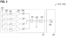
- FIG. 3 illustrates aspects with respect to the interfaces 1012, 1022.
- FIG. 3 illustrates a receive interface, but similar techniques may be readily applied to a transmit interface.
- the example of FIG. 3 illustrates an architecture of the interface 1012, 1022 that may be employed for so-called analog beamforming.
- Analog beamforming may typically employ a time-duplex configuration which is not capable of transmitting and/or receiving more than a single beam at each moment in time. Therefore, in a beam sweep according to analog beamforming, different beams of the beam sweep are not transmitted and/or received contemporaneously, but rather sequentially in time domain. This typically increases the time duration required for the beam sweep and, thus, increases the latency of subsequent transmission of data.
- the interface 1012, 1022 includes an analog domain 211 and a digital domain 251.
- the analog domain 211 includes various analog components 221 - 225, 231 - 233 configured for signal processing in the analog domain.
- the interface 1012, 1022 includes four antenna ports 221 for connection to the antennas 1014, 1024 of the respective antenna array 1013, 1023 (for sake of simplicity, in FIG. 3 , the antenna port 221 is only labeled for one of the received channels).
- a bandpass filter 222 and a RF switch 223 are provided.
- Programmable gain amplifiers 224 can implement channel-specific gains.
- the amplifiers 224 can be implemented by low-noise amplifiers.
- Phase sifters 225 are provided which can implement channel-specific phase shifts.
- demodulation is implemented by a multiplier 232 and a filter 233. Then, the analog baseband signal is forwarded to an analog-to-digital converter 261 of the digital domain 251.
- a beam configuration of a given beam defines a certain setting of the amplifiers 224 and the phase shifters 225.
- the processing of the antenna signals received via the plurality of antenna ports 221 is assigned to the analog domain. Therefore, at a given moment in time, a single beam according to the respective beam configuration can be implemented.
- FIG. 3 i.e., analog beamforming
- FIG. 4 Digital beamforming is illustrated by FIG. 4 .
- FIG. 4 illustrates aspects with respect to the interfaces 1012, 1022.
- FIG. 4 illustrates a receive interface, but similar techniques may be readily applied to a transmit interface.
- the example of FIG. 4 illustrates an architecture of the interface 1012, 1022 that may be employed for so-called digital beamforming.
- Digital beamforming may typically employ a time-duplex configuration which is capable of transmitting and/or receiving more than a single beam at each moment in time. Therefore, in a beam sweep, different beams of the beam sweep can be transmitted and/or received contemporaneously. This reduces the time duration required for the beam sweep; therefore, subsequent transmission of data can commence with reduced latency.
- demodulation is performed in parallel for each receive channel. Also, multiple analog-to-digital converters 261 are provisioned, one for each receive channel. The phase shifts are applied by a digital precoder 262.
- the setup of FIG. 4 i.e., digital beamforming, is associated with comparably high current consumption, because multiple analog-to-digital converters 261 are required.
- Digital beamforming may be employed using TDD between UL and DL; then, reciprocity applies. Digital beamforming could also be employed for FDD between UL and DL data transmission; then, reciprocity may not apply.
- FIG. 5 illustrates aspects with respect to the interfaces 1012, 1022.
- FIG. 5 illustrates a receive interface, but similar techniques may be readily applied to transmit interfaces.
- the example of FIG. 5 illustrates an architecture of the interface 1012, 1022 that may be employed for so-called hybrid beamforming.
- Hybrid beamforming may typically employ a time-duplex configuration which is capable of transmitting and/or receiving more than a single beam at each moment in time, wherein, however, the flexibility in time-multiplexing arbitrary beams is limited. From a comparison of FIGs. 3 and 4 with FIG. 5 , it is apparent that FIG. 5 employs an architecture logically arranged in-between the architectures of FIGs. 3 and 4 . I.e., hybrid beamforming is an intermediate scenarios between analog and digital beamforming.
- the number of analog-to-digital converters 261 in the architecture according to the example of FIG. 5 is larger than one, but smaller than the number of receive channels. Therefore, in the example of FIG. 5 , groups of two beams can be formed and the beams of each group can be received contemporaneously using the two analog-to-digital converters.
- the interfaces 1012, 1022 may have the capability of dynamically switching between the different architectures according to the examples of FIGs. 3 - 5 .
- the capabilities with respect to the time-duplex configuration may change. Dynamic adjustment of the beam sweeps in accordance with the dynamic changes to the time-duplex configuration becomes possible by the various examples described herein.
- FIG. 6 illustrates aspects with respect to a beam sweep 390.
- the beam sweep 390 is performed by the BS 101.
- the beam sweep 390 may be a DL transmit beam sweep or an UL receive beam sweep.
- FIG. 6 illustrates aspects with respect to the directional characteristics of the beam sweep 390.
- the beam sweep 390 includes a total of nine beams 301 - 309.
- the beams 301 - 309 are characterized by different spatial profiles; in particular, the direction of the peak of each one of the beams 301 - 309 is offset if compared to the direction of the neighboring peaks 301 - 309. Thereby, a peak-to-peak range or opening angle 351 of the beam sweep 390 is obtained.
- the beam sweep 390 can be characterized by a beam sweep configuration.
- the beam sweep configuration may define various parameters of the beam sweep 390 including, e.g., directional characteristics.
- the directional characteristics of the beam sweep configuration of the beam sweep 390 according to the example of FIG. 6 may specify that this beam sweep 390 includes a number of nine beams 301 - 309 at the illustrated two-dimensional spatial arrangement of the beams.
- the directional characteristics of the beam sweep 390 according to the example of FIG. 6 could also specify the peak-to-peak opening angle 351.
- the directional characteristics could specify a sequence with which the various beams 301 - 309 are activated.
- the directional characteristics could also specify a beam width of the various beams 301 - 309. While in the example of FIG. 6 a two-dimensional spatial arrangement of the beams 301-309 is illustrated, in other examples a three-dimensional spatial arrangement of beams would be possible.
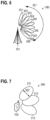
- FIG. 7 illustrates aspects with respect to a beam sweep 390.
- the beam sweep 390 is performed by the UE 102.
- the beam sweep 390 may be a UL transmit beam sweep or a DL receive beam sweep.
- FIG. 7 illustrates aspects with respect to the directional characteristics of the beam sweep 390.
- the beam sweep 390 according to the example of FIG. 7 includes a total of three beams 311 - 313.
- the beam width 352 of the beam 311 is illustrated exemplarily.
- the beam sweep 390 according to the example of FIG. 7 could be specified by a certain beam sweep configuration, including, e.g., respective directional characteristics.
- FIG. 8 illustrates aspects with respect to a beam sweep 390.
- FIG. 8 illustrates aspects with respect to frequency bands 410 allocated for the pilot signals 152 transmitted and/or received in the beam sweep 390 in accordance with the beam sweep configuration.
- the pilot signals 152 transmitted and/or received in the different beams 301 - 309 all employ the same frequency band 410.
- FIG. 8 illustrates aspects with respect to a time-duplex configuration of the beam sweep configuration of the beam sweep 390.
- the time-duplex configuration may generally define a time-alignment of the various beams 301-309 of the beam sweep.
- the time-duplex configuration may generally define a degree of time-parallelization of the transmission and/or reception of the pilot signals 151 on the various beams. This degree of time-parallelization may generally vary between no parallelization and full parallelization.
- the pilot signals 152 are not transmitted and/or received contemporaneously in the different beams 301 - 309.
- a sequential configuration using dedicated time slots 361 - 369 for each beam 301 - 309 of the beam sweep could be implemented by analog beamforming.
- FIG. 9 illustrates aspects with respect to a beam sweep 390.
- FIG. 9 illustrates aspects with respect to the time-duplex configuration of the beam sweep configuration of the beam sweep 390.
- some of the pilot signals 152 are transmitted and/or received contemporaneously in different beams 301 - 309.
- the pilot signals 152 are transmitted and/or received contemporaneously in time slot 361 in the beams 301 - 303.
- the pilot signals 152 are transmitted and/or received contemporaneously in time slot 365 in the beams 307 - 309.
- the pilot signals 152 transmitted and/or received in the beams 304 - 306 have dedicated timeslots 362 - 364.
- such a partly contemporaneous/partly sequential configuration of the beam sweep 390 could be implemented by hybrid beamforming.
- the time-duplex configuration of the beam sweep configuration could be indicative of at least two beams 301-303, 307-309 of the plurality of beams 301 - 309 of the beam sweep 390 for which the respective pilot signals 152 are transmitted and/or received contemporaneously.
- the respective time slots 361, 365 could be indicated together with links or pointers to the respective beams 301-303, 307-309.
- FIG. 10 illustrates aspects with respect to a beam sweep 390.
- FIG. 10 illustrates aspects with respect to frequency bands 410 allocated to the pilot signals 152 transmitted and/or received in the beam sweep 390 in accordance with the beam sweep configuration.
- the pilot signals 152 transmitted and/or received in the different beams 301 - 309 employ different frequency bands 410.
- FIG. 10 illustrates aspects with respect to a time-duplex configuration of the beam sweep configuration of the beams 390.
- the pilot signals 152 are all transmitted and/or received contemporaneously in the different beams 301 - 309 using a single time slot 361.
- such a fully contemporaneous configuration of the beam sweep could be implemented by digital beamforming.
- the time-duplex configuration of the beam sweep configuration could be indicative of at least two beams 301-309 of the plurality of beams 301 - 309 of the beam sweep 390 for which the respective pilot signals 152 are transmitted and/or received contemporaneously.
- the respective time slot 361 could be indicated together with links or pointers to the respective beams 301-309.
- the beam sweep configuration is not restricted to the time-duplex configuration. Other information may be included in the beam sweep configuration, additionally.
- the beam sweep configuration could be indicative of a time-per-beam 399 for the plurality of beams 301-309.
- the time-per-beam 399 could correspond to the duration of a transmission time interval.
- a further example of information included in the beam sweep configuration relates to the frequency bands 410 used for transmission of the pilot signals 152 in the beams 301-309.
- FIG. 11 illustrates aspects with respect to the frequency band 411 indicated by the beam sweep configuration and allocated for the UL pilot signals 152 on the wireless link 111.
- the frequency band 411 allocated by the UL pilot signals 152 has a bandwidth which is smaller than the bandwidth of the frequency band 401 allocated for the transmission of the UL data.
- FIG. 11 corresponds to a scenario where FDD is employed in order to mitigate interference between transmission of UL data and transmission of DL data.
- the frequency band 402 allocated for the transmission of DL data is different from frequency band 401 allocated for the transmission of the UL data.
- the bandwidth of the frequency band 412 allocated for the DL pilot signals 152 is again smaller than the bandwidth of the frequency band 402 allocated for the transmission of the DL data.
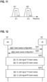
- FIG. 12 is a signaling diagram illustrating aspects with respect to exchange of beam sweep configurations 4001, 4002.
- the implementation of FIG. 12 could be implemented for the scenario of FIG. 11 .
- FDD of the transmission of data requires separate beam sweeps 391-394 for UL pilot signals 152 and DL pilot signals 152, respectively. This is because reciprocity between UL and DL may not be given. Generally, sometimes one or more or even all of the beam sweeps 391 - 394 may not be required, e.g., if the UE may benefit from reciprocity.
- a DL control message 5001 is transmitted by the BS 101 and received by the UE 102.
- the DL control message 5001 may be broadcasted by the BS 101, e.g., using a repeatedly transmitted system information block.
- the DL control message 5001 is indicative of a beam sweep configuration 4001.
- the DL control message 5001 could be indicative of a time-duplex configuration of the plurality of beams of one or more beam sweeps.
- the DL control message 5001 could be indicative of a frequency band 410-412 allocated for the pilot signals 152 transmitted and/or received in a plurality of beams of the one or more beam sweeps. Additionally, the DL control message 5002 could be indicative of directional characteristics of one or beam sweeps.
- an UL control message 5002 is transmitted by the UE 102 and received by the BS 101.
- the UL control message 5002 could be indicative of a time-duplex configuration of the plurality of beams of one or more beam sweeps.
- the UL control message 5002 could be indicative of a frequency band 410-412 allocated for the pilot signals 152 transmitted and/or received in a plurality of beams of the one or more beam sweeps.
- the UL control message 5002 could be indicative of directional characteristics of one or beam sweeps.
- the control messages 5001, 5002 could be Layer 2 or Layer 3 control messages according to the Open Systems Interconnect (OSI) model.
- OSI Open Systems Interconnect
- RRC Radio Resource Control
- the UE 102 could also receive control messages of further BSs (not illustrated in FIG. 12 ). I.e., it would be possible that the UE 102 receives control messages from BSs to which it is not connected or not camping on. This could facilitate subsequent handovers from a serving BS to a target BS in a cellular network. In particular, it would be possible that the UE 102 is aware of the beam sweep configuration of the target BS in the handover even prior to initiating direct bi-directional communication with the target BS. The latency of the handover can then be reduced. In particular, it may not be required to perform the exchange of the beam sweep configuration between the UE 102 and the target BS during the handover procedure; this can be done predictively.
- the UE 102 could share the beam sweep configuration with one or more further UEs connected via a device-to-device link, sometimes referred to as sidelink.
- a device-to-device link sometimes referred to as sidelink.
- Further examples include exchange of the beam sweep configuration between two BSs.
- beam sweeps 391, 392 each including a plurality of beams is executed.
- the beam sweep 391 is a transmit beam sweep of the BS 101 transmitting DL pilot signals 152.
- the beam sweep 392 is a receive beam sweep of the UE 102 receiving the DL pilot signals 152.
- the beam sweeps 391, 392 can be implemented in accordance with the beam sweep configuration 4001 indicated by the DL control message 5001.
- the beam sweeps 391, 392 can be time-synchronized.
- beam sweeps 393, 394 each including a plurality of beams are executed.
- the beam sweep 393 is a transmit beam sweep of the UE 102 transmitting UL pilot signals 152.
- the beam sweep 394 is a receive beam sweep of the BS 101 receiving the UL pilot signals 152.
- the beam sweeps 393, 394 can be implemented in accordance with the beam sweep configuration 4002 indicated by the UL control message 5002.
- the beam sweeps 393, 394 can be time-synchronized.
- the decision logic for determining the beam sweep configurations 4001, 4002 resides at the respective transmitting side, i.e., for the beam sweeps 391, 392 at the BS 101 and for the beam sweeps 393, 394 at the UE 102.
- the BS 101 and the UE 102 negotiate each beam sweep configuration using bidirectional control signaling.
- the BS 101 and the UE 102 exchange information on the respective beam sweep capabilities and that, in turn, the particular beam sweep configurations used for implementing the beam sweeps 391 - 394 are selected from a plurality of respectively defined candidate beam configurations exchanged between the BS 101 and the UE 102.
- the beam sweep capabilities may indicate support for analog, digital, or hybrid beamforming.
- the candidate beam configuration can differ between UL and DL. Different control message may be exchanged in this regard.
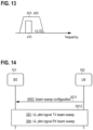
- FIG. 13 illustrates aspects with respect to the frequency band 411 indicated by the beam sweep configuration and allocated by the UL pilot signals 152 on the wireless link 111.
- the frequency band 411 allocated by the UL pilot signals 152 is smaller than the frequency band 401, 402 allocated for the transmission of the UL data and the DL data.
- FIG. 13 corresponds to a scenario where TDD is employed in order to mitigate interference between transmission of UL data and transmission of DL data. FDD is not employed.
- the frequency band 402 allocated for the transmission of DL data overlaps with the frequency band 401 allocated for the transmission of the UL data.
- FIG. 14 is a signaling diagram illustrating aspects with respect to exchange of a beam sweep configuration 4002.
- the implementation of FIG. 14 could be implemented for the scenario of FIG. 13 .
- a TDD configuration of the transmission of data does not require separate beam sweeps for UL pilot signals 152 and DL pilot signals 152, respectively. This is why the beam sweeps 393, 394 for the UL pilot signals 152 are employed, but beam sweeps for DL pilot signals 152 are not employed.
- a control message 5001 is indicative of the beam sweep configuration 4002 for the beam sweeps 393, 394.
- the reciprocity enables to determine the beam configuration of the beam used for transmission of DL data based on the beam configuration of the beam used for transmission of UL data; said beam configuration for transmission of the UL data can, in turn, be determined based on a receive property of the UL pilot signals 152 transmitted and received in the beam sweeps 393, 394 at block 5012.
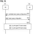
- FIG. 15 is a signaling diagram illustrating aspects with respect to exchange of a beam sweep configuration.
- the example of FIG. 15 generally corresponds to the example of FIG. 14 .
- the decision logic for determining the beam sweep configuration (4002) according to which the beam sweeps 393, 394 are configured does not solely reside at the UE 102, but rather also partly resides at the BS 101.
- the UE 102 sends a UL control message at 5021, the UL control message being indicative of a plurality of candidate beam sweep configurations 4011 supported by the capability of the UE 102.
- the BS 101 determines the beam sweep configuration 4002 based on the candidate beam sweep configurations 4011 and reports the selected beam sweep configuration 4002 using a DL control message 5022.
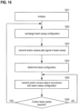
- FIG. 16 is a flowchart of a method according to various examples.
- communication between the BS 101 and the UE 102 is initiated in a standardized manner.
- the initialization according to block 1001 could be implemented using default beam configurations for beams used for transmission of data between the UE 102 and the BS 101.
- the initialization according to block 1001 could be implemented using predefined beam sweep configurations for beam sweeps including a plurality of beams for UL pilot signals 152 and/or DL pilot signals 152.
- a beam sweep configuration is exchanged between the BS 101 and the UE 102. This may include transmission of one or more control messages indicative of the beam sweep configuration and/or of the plurality of candidate beam sweep configurations.
- the BS 102 shares its beam sweep capability with the UE 102. This may correspond to exchanging a plurality of candidate beam sweep configurations between the BS 101 and the UE 102.
- the UE may select the beam sweep configuration from the plurality of candidate beam sweep configurations and indicate the latter to the BS 101.
- decision logic may be employed which determines the beam sweep configuration based on a selection from a plurality of candidate beam sweep configuration in view of different criteria.
- criteria may include latency of the subsequent transmission of data and/or energy consumption. For example, if the latency should be reduced, there may be a tendency towards digital beamforming transmitting and/or receiving pilot signals contemporaneously. Differently, if the energy consumption should be reduced, there may be a tendency towards analog beamforming not transmitting and/or receiving pilot signals contemporaneously. This may, in particular, apply for scenarios where the communication bandwidth is large.
- pilot signals 152 are transmitted and/or received (communicated) in one or more beam sweeps.
- the interfaces 1012, 1022 of the BS 101 and the UE 102 could be controlled to transmit and/or receive pilot signals 152 in a plurality of beams of the one or more beam sweeps and in accordance with the beam sweep configuration exchanged in block 1002.
- a beam configuration for subsequent transmission of UL data and/or DL data is determined based on a receive property of the pilot signals 152.
- the data is communicated in accordance with the beam sweep configuration determined at block 1004.
- block 1006 it is checked whether updated determination of the beam configuration should be triggered.
- Different decision criteria can be taken into account in block 1006. Examples include a downcount or timeout. Further examples include the mobility of the UE 102 and/or the BS 101. For example, if the mobility of the UE 102 exceeds a threshold, it can be judged in block 1006 that an updated beam configuration should be determined.
- blocks 1002 - 1004 are executed anew. Otherwise, communication of data in block 1005 commences with the previously determined beam configuration.
- FIG. 17 illustrates aspects with respect to the time synchronization of various beam sweeps 391 - 394.
- FIG. 7 illustrates aspects with respect to the time synchronization between the transmit beam sweep 391 for DL pilot signals 152 and the receive beam sweep 392 for the DL pilot signals 152, as well as aspects with respect to the time synchronization between the transmit beam sweep 393 for UL pilot signals 152 and the receive beam sweep 394 for the UL pilot signals 152.
- the scenario of FIG. 17 could be implemented in cases where, both, the BS 101, as well as the UE 102 support digital beamforming. Then, the BS 101, in time slot 361, transmits the DL pilot signals 152 in all beams 301 - 309 contemporaneously. For example, this could be done in a comparably narrow bandwidth 412 for each beam 301 - 309.
- the DL pilot signals 152 transmitted in the various beams 301 - 309 may be allocated in the same or different frequency bands 412.
- the UE 102 receives the DL pilot signals 152 in all beams 311 - 313 contemporaneously. Then, the UE 102 can be configured to determine the beam configuration based on the received properties of the DL pilot signals 152 received in the various beams 311 - 313. For example, the beam configuration could be selected in accordance with the particular beam 311 - 313 which has the strong a signal-to-noise ratio of the associated DL pilot signals 152. A corresponding beam configuration can be determined.
- the UE 102 transmits, in time slot 371 and contemporaneously on all beams 311 - 313, UL pilot signals 152 according to the beam sweep 393.
- the BS 101 receives the UL pilot signals 152 in the time slot 371 contemporaneously on all beams 301 - 309 according to the beam sweep 394. Then, the BS 101 can determine the appropriate beam configuration based on the receive property of the UL pilot signals 152.
- the time synchronization may be achieved by indicating the support for digital beamforming between the BS 101 and the UE 102, i.e., based on the respective time-duplex configuration indicated by the beam sweep configuration 4001, 4002, and/or indicating the time slot 361 used for transmission and reception of the pilot signals 152.
- FIG. 18 illustrates aspects with respect to the time synchronization of various beam sweeps 391 - 394.
- FIG. 18 illustrates aspects with respect to the time synchronization between the transmit beam sweep 391 for DL pilot signals 152 and the receive beam sweep 392 for the DL pilot signals 152, as well as aspects with respect to the time synchronization between the transmit beam sweep 393 for UL pilot signals 152 in the receive beam sweep 394 for the UL pilot signals 152.
- the scenario of FIG. 18 could be implemented in cases where the BS 101 supports digital beamforming while the UE 102 supports hybrid beamforming. This could be indicated by the time-duplex configuration of the beam sweep configuration 4001, 4002.
- the BS 102 transmits the DL pilot signals 152 in all beams 301 - 309 according to the beam sweep 391.
- the UE 102 in the time slot 361 receives the DL pilot signals 152 in the beams 311 - 312, but not in the beam 313; in the time slot 362, the UE 102 receives the DL pilot signals 152 in the beam 313.
- FIG. 19 illustrates aspects with respect to the time synchronization of various beam sweeps 391 - 394.
- FIG. 19 illustrates aspects with respect to the time synchronization between the transmit beam sweep 391 for DL pilot signals 152 and the receive beam sweep 392 for the DL pilot signals 152, as well as aspects with respect to the time synchronization between the transmit beam sweep 393 for UL pilot signals 152 and the receive beam sweep 394 for the UL pilot signals 152.
- the scenario of FIG. 19 could be implemented in cases where the BS 101 supports digital beamforming by the UE 102 supports analog beamforming. This could be indicated by the time-duplex configuration of the beam sweep configuration 4001, 4002.
- the BS 101 transmits the DL pilot signals 152 in the timeslots 361 - 363 in all beams 301 - 309 contemporaneously. This could be done in a comparably narrow bandwidth 412 for each beam 301 - 309.
- the various pilot signals 152 transmitted in the different beams 301 - 309 could be allocated on the same or on different frequencies.
- the UE 102 receives in a single beam 311 - 313 per time slot 361 - 363.
- the BS 101 can receive the UL pilot signals 152 in all beams 301 - 309 during the various timeslots 371 - 373.
- the beam sweeps 393, 394 may not be required. Rather, the UE 102 could transmit the UL pilot signal using the reciprocal beam configuration determined from the receive property of the DL pilot signals 152 received during the beam sweep 392.
- FIG. 20 illustrates aspects with respect to the time synchronization of various beam sweeps 391 - 392.
- FIG. 20 illustrates aspects with respect to the time synchronization between the transmit beam sweep 391 for DL pilot signals 152 and the receive beam sweep 392 for the DL pilot signals 152 (in FIG. 20 , for sake of simplicity, the entire beam sweeps 391, 392 are not illustrated, but rather only excerpts of the beam sweeps 391, 392).
- the scenario of FIG. 20 could be implemented in cases where the BS 101 supports analog beamforming and the UE 102 supports analog beamforming, as well.
- the BS 101 can transmit DL pilot signals 152 in the beam 301 in the subsequent timeslots 361 - 363. This could be done in a comparably narrow bandwidth 412.
- the UE 102 receives the DL pilot signals 152 transmitted in the beam 301 in different beams 311 - 313 for the subsequent timeslots 361 - 363.
- the BS 101 transmits the DL pilot signals 152 in the beam 302 and then in the beam 303, and so on. This can proceed until the receive property of the DL pilot signals 152 indicates a sufficient signal-to-noise ratio.
- the time-duplex configuration can indicate whether one of the scenarios according to FIGs. 17 - 20 applies where analog/digital beamforming is supported by the BS 101 and/or the UE 102, respectively.
- the beam sweep configuration is indicative of a time-per-beam for the plurality of beams 301 - 309, 311 - 313 of the beam sweeps 391 - 394.
- the time-per-beam can correspond to the duration of the various timeslots 361 - 369.
- the time-per-beam could also be expressed in terms of a sweep rate.
- the time synchronization is further facilitated by the directional characteristics of the beam sweeps 391 - 394 which may be indicative of the number of beams, etc. All such properties may be taken into account when time-synchronizing between transmit beam sweep and receive beam sweep.
- the beam sweep configuration can be indicative of the number of beams of the one or more beam sweeps, a beam width of the beams of the one or more beam sweeps, a time per beam for the beams of the one or more beam sweeps/a beam switching response time, a maximum supported bandwidth, etc.
- Time synchronization between transmit and receive beam sweeps can be achieved. This can take into account capability of the transmit and/or receive in terms of digital beamforming, analog beamforming, and hybrid beamforming.
- the beam sweep configuration could also be indicative of the periodicity between two beam sweeps, the time between two sweeps, or - generally - timing information regarding execution of the beam sweeps.
Claims (13)
- Procédé consistant à faire en sorte qu'un noeud (101, 102) d'un réseau (100) détermine une configuration de faisceau d'un faisceau (301-309, 311-313) utilisé pour l'émission de données sur une liaison sans fil (111) du réseau (100), le procédé comprenant :- l'échange, avec un autre noeud (101, 102) du réseau (100), d'une configuration de balayage de faisceau (4001, 4002),- l'émission et/ou la réception de signaux pilotes (152) dans une pluralité de faisceaux (301-309, 311-313) d'au moins un balayage de faisceau (390-394) qui est configuré conformément à la configuration de balayage de faisceau (4001, 4002),- la détermination de la configuration de faisceau sur la base d'une propriété de réception des signaux pilotes (152), et- la sélection de la configuration de balayage de faisceau (4001, 4002) parmi une pluralité de configurations de balayage de faisceau candidates (4011) échangées avec l'autre noeud (101, 102),dans lequel la configuration de balayage de faisceau (4001, 4002) est indicative d'une configuration de duplexage temporel de la pluralité de faisceaux (301-309, 311-313) de chaque balayage de faisceau (390-394) dudit au moins un balayage de faisceau (390-394).
- Procédé selon la revendication 1, comprenant en outre :- la mise en œuvre de la configuration de duplexage temporel en réaffectant le traitement de signaux d'antenne associés à une pluralité de ports d'antenne (221) d'une interface (1012, 1022) du noeud (101, 102) entre un domaine analogique (211) de l'interface (1012, 1022) et un domaine numérique (251) de l'interface (1012, 1022) lors de l'émission et/ou de la réception des signaux pilotes (152).
- Procédé selon les revendications 1 ou 2,
dans lequel la configuration de duplexage temporel est indicative d'au moins deux faisceaux (301-309, 311-313) de la pluralité de faisceaux (301-309, 311-313) de chaque balayage de faisceau (390-394) pour lesquels les signaux pilotes respectifs (152) sont émis et/ou reçus simultanément. - Procédé selon l'une quelconque des revendications 1- 3, comprenant en outre :- la synchronisation temporelle dudit au moins un balayage de faisceau (390-394) avec l'autre noeud (101, 102) sur la base de la configuration de duplexage temporel.
- Procédé selon l'une quelconque des revendications précédentes,
dans lequel la configuration de balayage de faisceau (4001, 4002) est en outre indicative d'un temps par faisceau pour la pluralité de faisceaux (301-309, 311-313) de chaque balayage de faisceau (390-394). - Procédé selon l'une quelconque des revendications précédentes,
dans lequel la configuration de balayage de faisceau (4001, 4002) est en outre indicative d'une bande de fréquences (410, 411, 412) allouée aux signaux pilotes (152) sur la liaison sans fil (111). - Procédé selon l'une quelconque des revendications précédentes,
dans lequel la configuration de balayage de faisceau (4001, 4002) est en outre indicative de caractéristiques directionnelles dudit au moins un balayage de faisceau (390-394), dans lequel les caractéristiques directionnelles sont facultativement choisies dans le groupe comprenant : un nombre de faisceaux (301-309, 311-313) ; une disposition spatiale bidimensionnelle des faisceaux (301-309, 311-313) ; une disposition spatiale tridimensionnelle des faisceaux (301-309, 311-313) ; une largeur de faisceau (352) des faisceaux (301-309, 311-313) ; un angle d'ouverture crête à crête (351) dudit au moins un balayage de faisceau (390-394) ; et une séquence de balayage de faisceaux (301-309, 311-313). - Procédé selon l'une quelconque des revendications précédentes, comprenant en outre :- la détermination de la configuration de balayage de faisceau (4001, 4002) sur la base d'au moins une exigence de latence de l'émission des données et d'une consommation d'énergie associée au balayage de faisceau (390-394) .
- Procédé selon l'une quelconque des revendications précédentes, comprenant en outre :- le déclenchement répété de ladite détermination de la configuration de faisceau sur la base d'au moins l'une d'une mobilité du noeud (101, 102) et d'une mobilité de l'autre noeud (101, 102).
- Procédé selon l'une quelconque des revendications précédentes,dans lequel ledit au moins un balayage de faisceau (390-394) comprend un balayage de faisceau d'émission (390-394) et/ou un balayage de faisceau de réception (390-394),dans lequel les signaux pilotes (152) comprennent des signaux pilotes de liaison montante (152) et/ou des signaux pilotes de liaison descendante (152).
- Procédé selon l'une quelconque des revendications précédentes, comprenant en outre :- la négociation de la configuration de balayage de faisceau (4001, 4002) avec l'autre noeud (101, 102) sur la base d'une capacité de balayage de faisceau, la capacité de balayage de faisceau comprenant au moins l'une de la formation de faisceau analogique, de la formation de faisceau numérique et de la formation de faisceau hybride.
- Procédé selon l'une quelconque des revendications précédentes,dans lequel le noeud (102) est un équipement d'utilisateur connecté au réseau (100) par l'intermédiaire d'une station de base (102),dans lequel l'autre noeud est choisi dans le groupe comprenant : la station de base (101) ; une station de base cible du réseau (101) vers laquelle un transfert de l'équipement d'utilisateur (102) est prédit ; un autre équipement d'utilisateur communiquant avec l'équipement d'utilisateur (101) par l'intermédiaire d'une liaison latérale du réseau (100).
- Noeud (101, 102) d'un réseau (100), comprenant :- une interface (1012, 1022) permettant l'émission sur une liaison sans fil (111) du réseau (100), et- un circuit de commande (1011, 1015, 1021, 1025) configuré pour déterminer une configuration de faisceau d'un faisceau (301-309, 311-313) utilisé pour l'émission de données par l'interface (1012, 1022) par : l'échange, avec un autre noeud (101, 102) du réseau (100), d'une configuration de balayage de faisceau (4001, 4002) ; la commande de l'interface (1012, 1022) pour émettre et/ou recevoir des signaux pilotes (152) dans une pluralité de faisceaux (301-309, 311-313) d'au moins un balayage de faisceau (390-394) qui est configuré conformément à la configuration de balayage de faisceau (4001, 4002) ; la détermination de la configuration de faisceau sur la base d'une propriété de réception des signaux pilotes (152),dans lequel la configuration de balayage de faisceau (4001, 4002) est sélectionnée parmi une pluralité de configurations de balayage de faisceau candidates (4011) échangées avec l'autre noeud (101, 102), etdans lequel la configuration de balayage de faisceau (4001, 4002) est indicative d'une configuration de duplexage temporel de la pluralité de faisceaux (301-309, 311-313) de chaque balayage de faisceau (390-394) dudit au moins un balayage de faisceau (390-394).
Priority Applications (1)
| Application Number | Priority Date | Filing Date | Title |
|---|---|---|---|
| EP23174963.1A EP4228169A1 (fr) | 2017-01-09 | 2018-01-05 | Configuration de balayage de faisceau |
Applications Claiming Priority (4)
| Application Number | Priority Date | Filing Date | Title |
|---|---|---|---|
| EP17150723 | 2017-01-09 | ||
| EP17154645 | 2017-02-03 | ||
| EP17176443 | 2017-06-16 | ||
| PCT/EP2018/050259 WO2018127558A1 (fr) | 2017-01-09 | 2018-01-05 | Configuration de balayage de faisceau |
Related Child Applications (1)
| Application Number | Title | Priority Date | Filing Date |
|---|---|---|---|
| EP23174963.1A Division EP4228169A1 (fr) | 2017-01-09 | 2018-01-05 | Configuration de balayage de faisceau |
Publications (2)
| Publication Number | Publication Date |
|---|---|
| EP3566332A1 EP3566332A1 (fr) | 2019-11-13 |
| EP3566332B1 true EP3566332B1 (fr) | 2023-05-31 |
Family
ID=60937769
Family Applications (4)
| Application Number | Title | Priority Date | Filing Date |
|---|---|---|---|
| EP23188935.3A Pending EP4243301A3 (fr) | 2017-01-09 | 2018-01-05 | Gestion de faisceau commandée par station de base |
| EP18700099.7A Active EP3566333B1 (fr) | 2017-01-09 | 2018-01-05 | Gestion de faisceau commandée par une station de base |
| EP18700097.1A Active EP3566332B1 (fr) | 2017-01-09 | 2018-01-05 | Configuration de balayage de faisceau |
| EP23174963.1A Pending EP4228169A1 (fr) | 2017-01-09 | 2018-01-05 | Configuration de balayage de faisceau |
Family Applications Before (2)
| Application Number | Title | Priority Date | Filing Date |
|---|---|---|---|
| EP23188935.3A Pending EP4243301A3 (fr) | 2017-01-09 | 2018-01-05 | Gestion de faisceau commandée par station de base |
| EP18700099.7A Active EP3566333B1 (fr) | 2017-01-09 | 2018-01-05 | Gestion de faisceau commandée par une station de base |
Family Applications After (1)
| Application Number | Title | Priority Date | Filing Date |
|---|---|---|---|
| EP23174963.1A Pending EP4228169A1 (fr) | 2017-01-09 | 2018-01-05 | Configuration de balayage de faisceau |
Country Status (6)
| Country | Link |
|---|---|
| US (3) | US11483812B2 (fr) |
| EP (4) | EP4243301A3 (fr) |
| JP (1) | JP7014803B2 (fr) |
| KR (1) | KR102345772B1 (fr) |
| CN (2) | CN110168957B (fr) |
| WO (3) | WO2018127558A1 (fr) |
Families Citing this family (29)
| Publication number | Priority date | Publication date | Assignee | Title |
|---|---|---|---|---|
| WO2018141163A1 (fr) * | 2017-09-30 | 2018-08-09 | 北京小米移动软件有限公司 | Procédé et appareil de transmission de données |
| US20210273701A1 (en) * | 2018-07-13 | 2021-09-02 | Sony Corporation | Time-overlapping beam-swept transmissions |
| CN110784922B (zh) * | 2018-07-27 | 2023-06-16 | 华硕电脑股份有限公司 | 处置无线通信中的侧链路资源的波束感测的方法和设备 |
| US11812449B2 (en) | 2018-08-10 | 2023-11-07 | Qualcomm Incorporated | Active beam management, configuration, and capability signaling |
| CN110913480B (zh) * | 2018-09-17 | 2023-03-31 | 华为技术有限公司 | 通信方法及相关装置 |
| US11349545B2 (en) * | 2018-11-02 | 2022-05-31 | Apple Inc. | Beam management without beam correspondence |
| US11070279B2 (en) * | 2018-12-14 | 2021-07-20 | Qualcomm Incorporated | Flexible beamforming techniques for wireless devices |
| US11394437B2 (en) | 2018-12-14 | 2022-07-19 | Qualcomm Incorporated | Beamforming codebook adaptation for flexible wireless devices |
| US11470489B2 (en) * | 2019-01-11 | 2022-10-11 | Qualcomm Incorporated | Synchronization signal block and physical downlink control channel search space monitoring based on user equipment beamforming capability |
| US11019632B2 (en) * | 2019-02-28 | 2021-05-25 | Qualcomm Incorporated | Beam update techniques in beamformed wireless communications |
| US11464066B2 (en) | 2019-04-05 | 2022-10-04 | Qualcomm Incorporated | Establishing radio bearers on millimeter wave frequencies for device-to-device communications |
| US11540106B2 (en) * | 2019-04-05 | 2022-12-27 | Qualcomm Incorporated | Beam sweeping on millimeter wave frequencies for device-to-device communications |
| CN113785522A (zh) * | 2019-05-10 | 2021-12-10 | 高通股份有限公司 | 侧链路的波束管理 |
| WO2021159407A1 (fr) | 2020-02-13 | 2021-08-19 | Nokia Shanghai Bell Co., Ltd. | Balayage de faisceau sur une transmission de signal de référence pour un positionnement d'ul |
| US11265076B2 (en) * | 2020-04-10 | 2022-03-01 | Totum Labs, Inc. | System and method for forward error correcting across multiple satellites |
| GB2594059A (en) * | 2020-04-14 | 2021-10-20 | Nokia Technologies Oy | Beam alignment techniques for telecommunication systems |
| WO2021246538A1 (fr) * | 2020-06-01 | 2021-12-09 | 엘지전자 주식회사 | Dispositif à métasurface à gradient de fréquence et procédé basé sur un système de direction de faisceau rapide |
| WO2022074194A1 (fr) * | 2020-10-08 | 2022-04-14 | Sony Group Corporation | Configuration d'un dispositif de communication sans fil pour faciliter des mesures d'angle d'arrivée au niveau d'un dispositif répéteur reconfigurable |
| KR20230088395A (ko) * | 2020-10-16 | 2023-06-19 | 프라운호퍼 게젤샤프트 쭈르 푀르데룽 데어 안겐반텐 포르슝 에. 베. | 반복 전송 개량 |
| US20230116740A1 (en) * | 2021-01-13 | 2023-04-13 | Apple Inc. | Cell reselection and measurement in a high-speed mode in wireless communications |
| EP4089932A1 (fr) * | 2021-04-22 | 2022-11-16 | Nokia Technologies Oy | Découverte de relais adaptative |
| US11552718B2 (en) * | 2021-05-12 | 2023-01-10 | Qualcomm Incorporated | Beam refinement and localization using true-time-delay analog arrays |
| US20230088577A1 (en) * | 2021-09-23 | 2023-03-23 | Qualcomm Incorporated | Beamforming configurations |
| US11804944B2 (en) * | 2021-11-10 | 2023-10-31 | Qualcomm Incorporated | Beam sweeping pattern switching |
| WO2023082194A1 (fr) * | 2021-11-12 | 2023-05-19 | 北京小米移动软件有限公司 | Procédé et appareil de traitement de faisceau, équipement utilisateur, réseau ris, station de base et support de stockage |
| US20230155650A1 (en) * | 2021-11-15 | 2023-05-18 | Qualcomm Incorporated | Heterogenous beamforming capability with mixed beamforming architecture |
| WO2023191446A1 (fr) * | 2022-03-31 | 2023-10-05 | 엘지전자 주식회사 | Procédé et dispositif pour mettre en œuvre une formation de faisceau adaptative dans un système de communication sans fil |
| WO2023206089A1 (fr) * | 2022-04-26 | 2023-11-02 | Telefonaktiebolaget Lm Ericsson (Publ) | Systèmes et procédés pour la transmission d'un signal de référence de sondage |
| CN117596675A (zh) * | 2022-08-08 | 2024-02-23 | 中兴通讯股份有限公司 | 波束配置方法、装置、存储介质及程序产品 |
Citations (1)
| Publication number | Priority date | Publication date | Assignee | Title |
|---|---|---|---|---|
| WO2018080660A1 (fr) * | 2016-10-28 | 2018-05-03 | Qualcomm Incorporated | Formation de faisceau de récepteur servant à mesurer |
Family Cites Families (22)
| Publication number | Priority date | Publication date | Assignee | Title |
|---|---|---|---|---|
| SE420965B (sv) | 1979-02-06 | 1981-11-09 | Philips Svenska Ab | Linsantenn |
| EP1562306A1 (fr) * | 2004-02-09 | 2005-08-10 | Alcatel | Sélection de faisceaux rapide avec mode de macrodiversité |
| KR101529852B1 (ko) * | 2008-01-02 | 2015-07-01 | 인터디지탈 테크날러지 코포레이션 | 협력적 무선 통신을 위한 방법 및 장치 |
| CN104092488B (zh) * | 2008-05-09 | 2018-01-19 | 苹果公司 | 用于支持蜂窝网络中天线波束形成的系统和方法 |
| WO2011042045A1 (fr) * | 2009-10-06 | 2011-04-14 | Nokia Siemens Networks Oy | Réservation des éléments d'un canal de signalisation commun pour une signalisation spécialisée |
| US8315154B2 (en) * | 2009-12-23 | 2012-11-20 | Intel Corporation | Time reduction for multiple link recovery |
| WO2013025070A2 (fr) * | 2011-08-16 | 2013-02-21 | Samsung Electronics Co., Ltd. | Appareil et procédé pour la prise en charge d'une transmission multiantenne dans un système de communication sans fil à faisceau formé |
| US9137698B2 (en) * | 2012-02-24 | 2015-09-15 | Samsung Electronics Co., Ltd. | Beam management for wireless communication |
| US9414371B2 (en) | 2012-04-16 | 2016-08-09 | Samsung Electronics Co., Ltd. | Hierarchical channel sounding and channel state information feedback in massive MIMO systems |
| US9380582B2 (en) * | 2012-04-16 | 2016-06-28 | Samsung Electronics Co., Ltd. | Methods and apparatus for flexible beam communications in random access in system with large number of antennas |
| KR20130127347A (ko) * | 2012-05-10 | 2013-11-22 | 삼성전자주식회사 | 아날로그 및 디지털 하이브리드 빔포밍을 통한 통신 방법 및 장치 |
| US10863313B2 (en) * | 2014-08-01 | 2020-12-08 | Polte Corporation | Network architecture and methods for location services |
| WO2015080648A1 (fr) | 2013-11-27 | 2015-06-04 | Telefonaktiebolaget L M Ericsson (Publ) | Procédés d'envoi et de réception d'un rapport contenant des informations d'état de canal |
| US10547418B2 (en) * | 2014-06-10 | 2020-01-28 | Qualcomm Incorporated | Coordinated operations of millimeter wavelength wireless access networks |
| US9363683B2 (en) | 2014-07-15 | 2016-06-07 | Qualcomm Incorporated | Asymmetric capability-driven methods for beam tracking in mm-wave access systems |
| US20190104549A1 (en) * | 2014-11-26 | 2019-04-04 | Idac Holdings, Inc. | Initial access in high frequency wireless systems |
| CN106922207B (zh) | 2014-12-16 | 2020-08-11 | 富士通株式会社 | 基于探测参考信号的下行信道估计方法、装置以及通信系统 |
| WO2016181332A1 (fr) * | 2015-05-14 | 2016-11-17 | Telefonaktiebolaget Lm Ericsson (Publ) | Procédures de mesure pour drs avec formation de faisceaux |
| WO2017045694A1 (fr) * | 2015-09-14 | 2017-03-23 | Nokia Solutions And Networks Oy | Transmission à formation de faisceau dans un système cellulaire |
| EP3726737A1 (fr) | 2016-03-03 | 2020-10-21 | IDAC Holdings, Inc. | Procédés et appareil de commande de faisceaux dans des systèmes à formation de faisceaux |
| WO2017195916A1 (fr) * | 2016-05-12 | 2017-11-16 | 엘지전자 주식회사 | Procédé et dispositif de réalisation de balayage du faisceau dans un système d'accès sans fil prenant en charge des ondes millimétriques |
| US10172071B2 (en) * | 2016-10-21 | 2019-01-01 | Qualcomm Incorporated | Directional synchronization in assisted millimeter wave systems |
-
2018
- 2018-01-05 EP EP23188935.3A patent/EP4243301A3/fr active Pending
- 2018-01-05 WO PCT/EP2018/050259 patent/WO2018127558A1/fr active Application Filing
- 2018-01-05 US US16/475,416 patent/US11483812B2/en active Active
- 2018-01-05 KR KR1020197020712A patent/KR102345772B1/ko active IP Right Grant
- 2018-01-05 WO PCT/EP2018/050261 patent/WO2018127560A1/fr active Application Filing
- 2018-01-05 CN CN201880006027.8A patent/CN110168957B/zh active Active
- 2018-01-05 US US16/476,021 patent/US10805920B2/en active Active
- 2018-01-05 EP EP18700099.7A patent/EP3566333B1/fr active Active
- 2018-01-05 JP JP2019537083A patent/JP7014803B2/ja active Active
- 2018-01-05 WO PCT/EP2018/050260 patent/WO2018127559A1/fr active Application Filing
- 2018-01-05 EP EP18700097.1A patent/EP3566332B1/fr active Active
- 2018-01-05 CN CN201880006038.6A patent/CN110168958B/zh active Active
- 2018-01-05 EP EP23174963.1A patent/EP4228169A1/fr active Pending
-
2020
- 2020-08-31 US US17/007,850 patent/US11044720B2/en active Active
Patent Citations (1)
| Publication number | Priority date | Publication date | Assignee | Title |
|---|---|---|---|---|
| WO2018080660A1 (fr) * | 2016-10-28 | 2018-05-03 | Qualcomm Incorporated | Formation de faisceau de récepteur servant à mesurer |
Also Published As
| Publication number | Publication date |
|---|---|
| US11044720B2 (en) | 2021-06-22 |
| CN110168958A (zh) | 2019-08-23 |
| US20190335430A1 (en) | 2019-10-31 |
| KR102345772B1 (ko) | 2021-12-31 |
| WO2018127558A1 (fr) | 2018-07-12 |
| US10805920B2 (en) | 2020-10-13 |
| KR20190110540A (ko) | 2019-09-30 |
| CN110168957A (zh) | 2019-08-23 |
| EP3566333A1 (fr) | 2019-11-13 |
| EP4243301A3 (fr) | 2023-10-11 |
| US11483812B2 (en) | 2022-10-25 |
| US20200413378A1 (en) | 2020-12-31 |
| EP3566332A1 (fr) | 2019-11-13 |
| CN110168958B (zh) | 2022-12-23 |
| WO2018127559A1 (fr) | 2018-07-12 |
| US20190379441A1 (en) | 2019-12-12 |
| EP4228169A1 (fr) | 2023-08-16 |
| WO2018127560A1 (fr) | 2018-07-12 |
| JP7014803B2 (ja) | 2022-02-01 |
| EP3566333B1 (fr) | 2023-08-02 |
| EP4243301A2 (fr) | 2023-09-13 |
| CN110168957B (zh) | 2022-06-28 |
| JP2020509626A (ja) | 2020-03-26 |
Similar Documents
| Publication | Publication Date | Title |
|---|---|---|
| EP3566332B1 (fr) | Configuration de balayage de faisceau | |
| CN109997313B (zh) | 用于上行链路发送的方法 | |
| CN105830496B (zh) | 波束成形系统中的控制信令发送 | |
| EP3158787B1 (fr) | Recueil d'informations d'état de canal pour système de communications sans fil avec conformation de faisceaux | |
| JP6285609B2 (ja) | 無線接続システムにおいて多重ランク支援のためのハイブリッドビームフォーミング方法及び装置 | |
| EP2887561A1 (fr) | Appareils, procédés et programmes informatiques de formation de faisceaux pour un émetteur/récepteur de station de base et un émetteur/récepteur mobile | |
| WO2015080648A1 (fr) | Procédés d'envoi et de réception d'un rapport contenant des informations d'état de canal | |
| WO2015080645A1 (fr) | Nœud de réseau, dispositif sans fil, procédés intégrés, programmes informatiques et supports lisibles par ordinateur comprenant les programmes informatiques pour, respectivement, recevoir et envoyer un compte-rendu | |
| CN109526245B (zh) | 具有主收发器和辅收发器的无线电收发设备和利用该设备提供初始接入的方法 | |
| EP3637634B1 (fr) | Réacquisition de faisceau opportuniste | |
| EP4209065A1 (fr) | Avance temporelle dans une communication en duplex intégral | |
| US11626911B2 (en) | Flexible beamforming control | |
| US11569583B2 (en) | Multi-beam routing using a lens antenna | |
| EP4209066A1 (fr) | Améliorations d'avance temporelle en duplex intégral | |
| CN116097683A (zh) | 协调与使用多个订阅的用户设备的多个连接 | |
| US11985617B2 (en) | Full duplex timing advance enhancements |
Legal Events
| Date | Code | Title | Description |
|---|---|---|---|
| STAA | Information on the status of an ep patent application or granted ep patent |
Free format text: STATUS: UNKNOWN |
|
| STAA | Information on the status of an ep patent application or granted ep patent |
Free format text: STATUS: THE INTERNATIONAL PUBLICATION HAS BEEN MADE |
|
| PUAI | Public reference made under article 153(3) epc to a published international application that has entered the european phase |
Free format text: ORIGINAL CODE: 0009012 |
|
| STAA | Information on the status of an ep patent application or granted ep patent |
Free format text: STATUS: REQUEST FOR EXAMINATION WAS MADE |
|
| 17P | Request for examination filed |
Effective date: 20190806 |
|
| AK | Designated contracting states |
Kind code of ref document: A1 Designated state(s): AL AT BE BG CH CY CZ DE DK EE ES FI FR GB GR HR HU IE IS IT LI LT LU LV MC MK MT NL NO PL PT RO RS SE SI SK SM TR |
|
| AX | Request for extension of the european patent |
Extension state: BA ME |
|
| DAV | Request for validation of the european patent (deleted) | ||
| DAX | Request for extension of the european patent (deleted) | ||
| STAA | Information on the status of an ep patent application or granted ep patent |
Free format text: STATUS: EXAMINATION IS IN PROGRESS |
|
| STAA | Information on the status of an ep patent application or granted ep patent |
Free format text: STATUS: EXAMINATION IS IN PROGRESS |
|
| 17Q | First examination report despatched |
Effective date: 20201026 |
|
| STAA | Information on the status of an ep patent application or granted ep patent |
Free format text: STATUS: EXAMINATION IS IN PROGRESS |
|
| GRAP | Despatch of communication of intention to grant a patent |
Free format text: ORIGINAL CODE: EPIDOSNIGR1 |
|
| STAA | Information on the status of an ep patent application or granted ep patent |
Free format text: STATUS: GRANT OF PATENT IS INTENDED |
|
| INTG | Intention to grant announced |
Effective date: 20220516 |
|
| GRAJ | Information related to disapproval of communication of intention to grant by the applicant or resumption of examination proceedings by the epo deleted |
Free format text: ORIGINAL CODE: EPIDOSDIGR1 |
|
| STAA | Information on the status of an ep patent application or granted ep patent |
Free format text: STATUS: EXAMINATION IS IN PROGRESS |
|
| INTC | Intention to grant announced (deleted) | ||
| GRAP | Despatch of communication of intention to grant a patent |
Free format text: ORIGINAL CODE: EPIDOSNIGR1 |
|
| STAA | Information on the status of an ep patent application or granted ep patent |
Free format text: STATUS: GRANT OF PATENT IS INTENDED |
|
| INTG | Intention to grant announced |
Effective date: 20221115 |
|
| GRAS | Grant fee paid |
Free format text: ORIGINAL CODE: EPIDOSNIGR3 |
|
| GRAA | (expected) grant |
Free format text: ORIGINAL CODE: 0009210 |
|
| STAA | Information on the status of an ep patent application or granted ep patent |
Free format text: STATUS: THE PATENT HAS BEEN GRANTED |
|
| RAP1 | Party data changed (applicant data changed or rights of an application transferred) |
Owner name: SONY GROUP CORPORATION |
|
| AK | Designated contracting states |
Kind code of ref document: B1 Designated state(s): AL AT BE BG CH CY CZ DE DK EE ES FI FR GB GR HR HU IE IS IT LI LT LU LV MC MK MT NL NO PL PT RO RS SE SI SK SM TR |
|
| REG | Reference to a national code |
Ref country code: GB Ref legal event code: FG4D Ref country code: CH Ref legal event code: EP |
|
| REG | Reference to a national code |
Ref country code: DE Ref legal event code: R096 Ref document number: 602018050405 Country of ref document: DE |
|
| REG | Reference to a national code |
Ref country code: AT Ref legal event code: REF Ref document number: 1571587 Country of ref document: AT Kind code of ref document: T Effective date: 20230615 |
|
| REG | Reference to a national code |
Ref country code: IE Ref legal event code: FG4D |
|
| REG | Reference to a national code |
Ref country code: NL Ref legal event code: FP |
|
| REG | Reference to a national code |
Ref country code: SE Ref legal event code: TRGR |
|
| REG | Reference to a national code |
Ref country code: LT Ref legal event code: MG9D |
|
| REG | Reference to a national code |
Ref country code: AT Ref legal event code: MK05 Ref document number: 1571587 Country of ref document: AT Kind code of ref document: T Effective date: 20230531 |
|
| PG25 | Lapsed in a contracting state [announced via postgrant information from national office to epo] |
Ref country code: NO Free format text: LAPSE BECAUSE OF FAILURE TO SUBMIT A TRANSLATION OF THE DESCRIPTION OR TO PAY THE FEE WITHIN THE PRESCRIBED TIME-LIMIT Effective date: 20230831 Ref country code: ES Free format text: LAPSE BECAUSE OF FAILURE TO SUBMIT A TRANSLATION OF THE DESCRIPTION OR TO PAY THE FEE WITHIN THE PRESCRIBED TIME-LIMIT Effective date: 20230531 Ref country code: AT Free format text: LAPSE BECAUSE OF FAILURE TO SUBMIT A TRANSLATION OF THE DESCRIPTION OR TO PAY THE FEE WITHIN THE PRESCRIBED TIME-LIMIT Effective date: 20230531 |
|
| PG25 | Lapsed in a contracting state [announced via postgrant information from national office to epo] |
Ref country code: RS Free format text: LAPSE BECAUSE OF FAILURE TO SUBMIT A TRANSLATION OF THE DESCRIPTION OR TO PAY THE FEE WITHIN THE PRESCRIBED TIME-LIMIT Effective date: 20230531 Ref country code: PL Free format text: LAPSE BECAUSE OF FAILURE TO SUBMIT A TRANSLATION OF THE DESCRIPTION OR TO PAY THE FEE WITHIN THE PRESCRIBED TIME-LIMIT Effective date: 20230531 Ref country code: LV Free format text: LAPSE BECAUSE OF FAILURE TO SUBMIT A TRANSLATION OF THE DESCRIPTION OR TO PAY THE FEE WITHIN THE PRESCRIBED TIME-LIMIT Effective date: 20230531 Ref country code: LT Free format text: LAPSE BECAUSE OF FAILURE TO SUBMIT A TRANSLATION OF THE DESCRIPTION OR TO PAY THE FEE WITHIN THE PRESCRIBED TIME-LIMIT Effective date: 20230531 Ref country code: IS Free format text: LAPSE BECAUSE OF FAILURE TO SUBMIT A TRANSLATION OF THE DESCRIPTION OR TO PAY THE FEE WITHIN THE PRESCRIBED TIME-LIMIT Effective date: 20230930 Ref country code: HR Free format text: LAPSE BECAUSE OF FAILURE TO SUBMIT A TRANSLATION OF THE DESCRIPTION OR TO PAY THE FEE WITHIN THE PRESCRIBED TIME-LIMIT Effective date: 20230531 Ref country code: GR Free format text: LAPSE BECAUSE OF FAILURE TO SUBMIT A TRANSLATION OF THE DESCRIPTION OR TO PAY THE FEE WITHIN THE PRESCRIBED TIME-LIMIT Effective date: 20230901 |
|
| PG25 | Lapsed in a contracting state [announced via postgrant information from national office to epo] |
Ref country code: FI Free format text: LAPSE BECAUSE OF FAILURE TO SUBMIT A TRANSLATION OF THE DESCRIPTION OR TO PAY THE FEE WITHIN THE PRESCRIBED TIME-LIMIT Effective date: 20230531 |
|
| PG25 | Lapsed in a contracting state [announced via postgrant information from national office to epo] |
Ref country code: SK Free format text: LAPSE BECAUSE OF FAILURE TO SUBMIT A TRANSLATION OF THE DESCRIPTION OR TO PAY THE FEE WITHIN THE PRESCRIBED TIME-LIMIT Effective date: 20230531 |
|
| PGFP | Annual fee paid to national office [announced via postgrant information from national office to epo] |
Ref country code: GB Payment date: 20231219 Year of fee payment: 7 |
|
| PG25 | Lapsed in a contracting state [announced via postgrant information from national office to epo] |
Ref country code: SM Free format text: LAPSE BECAUSE OF FAILURE TO SUBMIT A TRANSLATION OF THE DESCRIPTION OR TO PAY THE FEE WITHIN THE PRESCRIBED TIME-LIMIT Effective date: 20230531 Ref country code: SK Free format text: LAPSE BECAUSE OF FAILURE TO SUBMIT A TRANSLATION OF THE DESCRIPTION OR TO PAY THE FEE WITHIN THE PRESCRIBED TIME-LIMIT Effective date: 20230531 Ref country code: RO Free format text: LAPSE BECAUSE OF FAILURE TO SUBMIT A TRANSLATION OF THE DESCRIPTION OR TO PAY THE FEE WITHIN THE PRESCRIBED TIME-LIMIT Effective date: 20230531 Ref country code: PT Free format text: LAPSE BECAUSE OF FAILURE TO SUBMIT A TRANSLATION OF THE DESCRIPTION OR TO PAY THE FEE WITHIN THE PRESCRIBED TIME-LIMIT Effective date: 20231002 Ref country code: EE Free format text: LAPSE BECAUSE OF FAILURE TO SUBMIT A TRANSLATION OF THE DESCRIPTION OR TO PAY THE FEE WITHIN THE PRESCRIBED TIME-LIMIT Effective date: 20230531 Ref country code: DK Free format text: LAPSE BECAUSE OF FAILURE TO SUBMIT A TRANSLATION OF THE DESCRIPTION OR TO PAY THE FEE WITHIN THE PRESCRIBED TIME-LIMIT Effective date: 20230531 Ref country code: CZ Free format text: LAPSE BECAUSE OF FAILURE TO SUBMIT A TRANSLATION OF THE DESCRIPTION OR TO PAY THE FEE WITHIN THE PRESCRIBED TIME-LIMIT Effective date: 20230531 |
|
| PGFP | Annual fee paid to national office [announced via postgrant information from national office to epo] |
Ref country code: SE Payment date: 20231219 Year of fee payment: 7 Ref country code: NL Payment date: 20231219 Year of fee payment: 7 Ref country code: FR Payment date: 20231219 Year of fee payment: 7 |
|
| REG | Reference to a national code |
Ref country code: DE Ref legal event code: R097 Ref document number: 602018050405 Country of ref document: DE |
|
| PLBE | No opposition filed within time limit |
Free format text: ORIGINAL CODE: 0009261 |
|
| STAA | Information on the status of an ep patent application or granted ep patent |
Free format text: STATUS: NO OPPOSITION FILED WITHIN TIME LIMIT |
|
| PGFP | Annual fee paid to national office [announced via postgrant information from national office to epo] |
Ref country code: DE Payment date: 20231219 Year of fee payment: 7 |
|
| PG25 | Lapsed in a contracting state [announced via postgrant information from national office to epo] |
Ref country code: SI Free format text: LAPSE BECAUSE OF FAILURE TO SUBMIT A TRANSLATION OF THE DESCRIPTION OR TO PAY THE FEE WITHIN THE PRESCRIBED TIME-LIMIT Effective date: 20230531 |
|
| 26N | No opposition filed |
Effective date: 20240301 |