EP3566254B1 - Stopfen zum verschliessen und abdichten einer öffnung in einem gehäuse eines energiespeichersystems und energiespeichersystem - Google Patents
Stopfen zum verschliessen und abdichten einer öffnung in einem gehäuse eines energiespeichersystems und energiespeichersystem Download PDFInfo
- Publication number
- EP3566254B1 EP3566254B1 EP17835666.3A EP17835666A EP3566254B1 EP 3566254 B1 EP3566254 B1 EP 3566254B1 EP 17835666 A EP17835666 A EP 17835666A EP 3566254 B1 EP3566254 B1 EP 3566254B1
- Authority
- EP
- European Patent Office
- Prior art keywords
- plug
- sealing element
- region
- sealing
- opening
- Prior art date
- Legal status (The legal status is an assumption and is not a legal conclusion. Google has not performed a legal analysis and makes no representation as to the accuracy of the status listed.)
- Active
Links
Images


Classifications
-
- H—ELECTRICITY
- H01—ELECTRIC ELEMENTS
- H01M—PROCESSES OR MEANS, e.g. BATTERIES, FOR THE DIRECT CONVERSION OF CHEMICAL ENERGY INTO ELECTRICAL ENERGY
- H01M50/00—Constructional details or processes of manufacture of the non-active parts of electrochemical cells other than fuel cells, e.g. hybrid cells
- H01M50/10—Primary casings; Jackets or wrappings
- H01M50/183—Sealing members
- H01M50/184—Sealing members characterised by their shape or structure
-
- H—ELECTRICITY
- H01—ELECTRIC ELEMENTS
- H01M—PROCESSES OR MEANS, e.g. BATTERIES, FOR THE DIRECT CONVERSION OF CHEMICAL ENERGY INTO ELECTRICAL ENERGY
- H01M50/00—Constructional details or processes of manufacture of the non-active parts of electrochemical cells other than fuel cells, e.g. hybrid cells
- H01M50/60—Arrangements or processes for filling or topping-up with liquids; Arrangements or processes for draining liquids from casings
- H01M50/609—Arrangements or processes for filling with liquid, e.g. electrolytes
- H01M50/627—Filling ports
- H01M50/636—Closing or sealing filling ports, e.g. using lids
- H01M50/645—Plugs
-
- H—ELECTRICITY
- H01—ELECTRIC ELEMENTS
- H01M—PROCESSES OR MEANS, e.g. BATTERIES, FOR THE DIRECT CONVERSION OF CHEMICAL ENERGY INTO ELECTRICAL ENERGY
- H01M50/00—Constructional details or processes of manufacture of the non-active parts of electrochemical cells other than fuel cells, e.g. hybrid cells
- H01M50/20—Mountings; Secondary casings or frames; Racks, modules or packs; Suspension devices; Shock absorbers; Transport or carrying devices; Holders
- H01M50/204—Racks, modules or packs for multiple batteries or multiple cells
-
- H—ELECTRICITY
- H01—ELECTRIC ELEMENTS
- H01M—PROCESSES OR MEANS, e.g. BATTERIES, FOR THE DIRECT CONVERSION OF CHEMICAL ENERGY INTO ELECTRICAL ENERGY
- H01M50/00—Constructional details or processes of manufacture of the non-active parts of electrochemical cells other than fuel cells, e.g. hybrid cells
- H01M50/20—Mountings; Secondary casings or frames; Racks, modules or packs; Suspension devices; Shock absorbers; Transport or carrying devices; Holders
- H01M50/249—Mountings; Secondary casings or frames; Racks, modules or packs; Suspension devices; Shock absorbers; Transport or carrying devices; Holders specially adapted for aircraft or vehicles, e.g. cars or trains
-
- H—ELECTRICITY
- H01—ELECTRIC ELEMENTS
- H01M—PROCESSES OR MEANS, e.g. BATTERIES, FOR THE DIRECT CONVERSION OF CHEMICAL ENERGY INTO ELECTRICAL ENERGY
- H01M10/00—Secondary cells; Manufacture thereof
- H01M10/06—Lead-acid accumulators
-
- H—ELECTRICITY
- H01—ELECTRIC ELEMENTS
- H01M—PROCESSES OR MEANS, e.g. BATTERIES, FOR THE DIRECT CONVERSION OF CHEMICAL ENERGY INTO ELECTRICAL ENERGY
- H01M2220/00—Batteries for particular applications
- H01M2220/20—Batteries in motive systems, e.g. vehicle, ship, plane
-
- Y—GENERAL TAGGING OF NEW TECHNOLOGICAL DEVELOPMENTS; GENERAL TAGGING OF CROSS-SECTIONAL TECHNOLOGIES SPANNING OVER SEVERAL SECTIONS OF THE IPC; TECHNICAL SUBJECTS COVERED BY FORMER USPC CROSS-REFERENCE ART COLLECTIONS [XRACs] AND DIGESTS
- Y02—TECHNOLOGIES OR APPLICATIONS FOR MITIGATION OR ADAPTATION AGAINST CLIMATE CHANGE
- Y02E—REDUCTION OF GREENHOUSE GAS [GHG] EMISSIONS, RELATED TO ENERGY GENERATION, TRANSMISSION OR DISTRIBUTION
- Y02E60/00—Enabling technologies; Technologies with a potential or indirect contribution to GHG emissions mitigation
- Y02E60/10—Energy storage using batteries
Definitions
- the present invention relates to a plug for closing and sealing an opening in a housing of an energy storage system. Furthermore, the invention relates to an energy storage system with at least one such plug.
- plugs for closing an opening in a housing of, for example, an energy storage system usually have round or flat sealing rings which are loosely accommodated in a groove in the plug and usually only partially fill it.
- sealing rings of conventional plugs are usually in the form of O-rings. These are based on being deformed by a radial crushing stress that occurs during the screwing-in process and on creating a sealing effect due to this crushing stress.
- sealing rings are subject to high levels of wear. For example, frequent installation and removal of the plug can lead to a deterioration of the sealing ring material, which can reduce the sealing effect. On the other hand, the material can also be damaged by frequent temperature changes. This also leads to a reduced sealing effect.
- conventional sealing rings manufactured separately must be installed using a complex assembly process. This makes installing the sealing rings on the plug time-consuming and costly.
- the EP 1 156 538 A2 relates to another conventional plug arrangement for a battery, which has a round seal, preferably designed as an O-ring, and a lamellar seal.
- the round seal seals a cavity from the atmosphere surrounding the battery and the lamellar seal seals the cavity from the interior of the cell.
- the cavity is fluidically connected to the interior of the cell via an opening formed in the plug arrangement in order to enable degassing of the battery and, if necessary, a backflow of acid into the interior of the cell.
- EP 0 920 063 A1 relates to another conventional plug system for closing cell openings of a rechargeable battery, which has a plug body that can be inserted into a cell opening and in which a plug and a valve element are arranged.
- the plug body is essentially made of a circular cylinder, which has a section with an opening in a middle part that is reduced compared to the plug body outer diameter.
- the plug body has a first sealing element designed as a molded O-ring for sealing against an external environment and can have a second sealing element designed as an O-ring below a reduced section formed in the middle part for sealing against the interior of the housing.
- the plug arrangement can have a sealing element that is not rotationally symmetrical and that leaves a volume space free in some areas, which provides a fluidic connection to the interior of the cell.
- the object of the present invention is therefore to provide an improved plug which does not have the disadvantages of the prior art and, moreover, is simple and inexpensive to manufacture and assemble.
- a plug for closing and sealing an opening in a housing of an energy storage system, in particular for closing and sealing an opening in a housing of a lead-acid accumulator.
- the plug has a connection area that is designed to engage with the opening of the energy storage system, and a sealing area arranged in the axial direction of the plug above the connection area.
- the sealing area is designed to accommodate a sealing element that is designed to be deformed in the installed state of the plug by a force acting entirely in the axial direction of the plug.
- the plug according to the invention can be used to close and seal an opening in a housing cost-effectively and safely.
- the sealing element which is deformed by a force acting at least partially, in particular completely, in the axial direction of the plug, is not weakened even under higher thermal and/or mechanical (dynamic) loads.
- the plug and the housing of the energy storage system can carry out at least minimal counter-movements to one another, which can be caused, for example, by vibrations of the energy storage system.
- a conventional sealing element - such as an O-ring - such counter-movements would quickly lead to a deterioration of the material of the sealing element and thus to a deterioration of the sealing effect.
- the sealing element according to the invention is deformed by a force acting at least partially, in particular completely, in the axial direction of the plug, the mechanical load on the sealing element due to vibrations or due to counter-movements of the plug and the housing is low. Furthermore, the fact that the sealing element is at least essentially not subject to deformation caused by radial forces also prevents the material of the sealing element from deteriorating. As a result, a sealing effect can be guaranteed even under dynamic loads.
- Lengthening of the plug can also be avoided or reduced by arranging the sealing element above the connection area in the axial direction of the plug. Lengthening the plug would lead to a reduction in force and thus to a reduction in the sealing effect.
- the sealing element undergoes at least substantially no radial deformation, the mechanical and/or thermal resistance of the sealing element is also advantageously improved.
- the sealing area is designed to accommodate the sealing element in such a way that a sealing effect of the sealing element is generated by the force acting entirely in the axial direction of the plug.
- the sealing effect is generated by the force acting at least partially, in particular completely, in the axial direction of the plug, the sealing effect is permanently guaranteed even under higher thermal and/or mechanical (dynamic) stresses.
- the sealing effect is generated by the force that arises during assembly of the plug and acts at least partially, in particular completely, in the axial direction of the plug.
- the restoring force of the sealing element which is caused by the assembly, also contributes to the sealing effect.
- This force coupling allows the sealing effect to be maintained even under high thermal influences, which could otherwise cause a reduction in both forces, for example by changing the material properties or by generating "settling" movements.
- the generation of "settling" movements or “settling” is understood to mean a loss of the pre-tensioning force of the connection when the plug is installed.
- a cross-section of the sealing element in particular already in a non-installed state of the plug, has at least substantially an L-shape.
- the sealing element By giving the cross-section of the sealing element a shape that is essentially different from a circular shape, it is ensured that the sealing element can be deformed at least essentially, in particular completely, in the axial direction, in particular without deforming the sealing element in the radial direction. This makes it easier to assemble the plug, in particular to repeatedly assemble and/or disassemble the plug, and on the other hand the sealing effect is further advantageously improved even under higher thermal and/or mechanical (dynamic) loads.
- the sealing element has a first region on a side of the sealing element facing the connection region and a second region on a side of the sealing element facing away from the connection region.
- the second area of the sealing element has a larger outer diameter than the first area even when the plug is not installed.
- At least one area of the sealing element is completely circumferential and rotationally symmetrical. This advantageously makes it easy to manufacture the sealing element. This can also reduce manufacturing costs.
- the sealing element in particular a second region of the sealing element, in an installed state of the plug is in engagement with a sealing rib which extends along an inner circumference of the opening receiving the plug, in particular a region of the opening receiving a plug body, upwards in the direction of the sealing region of the plug, as seen in the axial direction of the plug, and which is designed to exert the force acting at least partially, in particular completely, in the axial direction of the plug on the sealing element, in particular on the second region of the sealing element.
- the plug has a plug head and a plug body, with the plug body in turn having the connection area and the sealing area.
- the sealing area borders on the plug head on one side and on the connection area on the opposite side.
- the sealing rib interacting with the sealing element advantageously creates a force coupling that can increase the sealing effect of the sealing element.
- the force coupling is created on the one hand by the force acting in the axial direction of the plug during assembly, and on the other hand by a restoring force of the sealing element, which is caused by the force acting in the axial direction of the plug.
- the sealing effect can advantageously be maintained even in the event of high thermal and/or mechanical (dynamic) influences.
- Such high thermal and/or mechanical influences can, on the one hand, cause a reduction in both forces, in particular by changing the material properties or generating "settling" movements, i.e. a loss of the preload force of the connection when the plug is installed.
- the plug in the sealing region has a groove running along a circumference of the plug, into which the sealing element is at least partially molded.
- the outermost surface of the plug can be melted at least in some areas by injecting the sealing element. This can create a material bond between the plug and the sealing element.
- injecting the sealing element onto the plug is easy to implement, for example in a (known) two-component injection molding process. Because the groove already specifies the shape of the sealing element in some areas or at least corresponds to it in some areas, costs can also be saved advantageously because the tool does not have to be as complicated.
- the plug is made of a first plastic material, in particular a thermoplastic material, in particular injection-molded.
- a first plastic material in particular a thermoplastic material, in particular injection-molded.
- the sealing element is made of a second plastic material, in particular an elastomer, a thermoplastic elastomer, a silicone and/or a silicone-like substance.
- the effect of the force coupling can be further increased by choosing a suitable material for the sealing element.
- the sealing effect of the sealing element can be guaranteed even under high thermal and/or mechanical (dynamic) influences.
- the sealing effect can also be maintained when a "settling" movement occurs, i.e. the loss of the pre-tensioning force.
- the plug is completely receivable or received by the opening of the housing of the energy storage system, in such a way that the plug is flush with an outer side of the housing.
- connection region of the plug has an external thread for the positive and non-positive connection of the plug to the opening.
- connection region is designed as a plug connection for the positive and/or non-positive connection of the plug to the opening.
- a plug connection can be assembled and disassembled more quickly and is also easier to manufacture.
- At least one locking lug can also be formed on the plug connection in order to form-fit the plug to a corresponding recess in the opening of the housing.
- a circumferential projection is arranged in the sealing region between the sealing element and the connecting region, by means of which the sealing element is spaced by 2 mm to 6 mm, preferably by 3 mm to 5 mm, from the connecting region, in particular an uppermost thread of the connecting region as seen in the axial direction of the plug.
- the sealing element in particular a first region of the sealing element, is at least substantially undeformed in the radial direction of the plug even when the plug is in the installed state.
- an energy storage system for use in a vehicle which comprises a plurality of energy storage cells and a housing which is designed to accommodate the plurality of energy storage cells and which has at least one opening, in particular at least one filling opening for filling the housing with a liquid electrolyte.
- Each opening can be closed or closed with the aid of a plug assigned to the respective opening and as already described.
- openings in the energy storage system can be closed in an advantageously simple and cost-effective manner.
- the openings can be opened or closed several times, for example if water and/or liquid electrolyte needs to be refilled, without reducing the sealing effect of the sealing element.
- FIG. 1 shows a schematic representation of a vehicle 200, which has at least one energy storage system 100.
- the energy storage system 100 further comprises a plurality of energy storage cells, wherein a plurality of energy storage cells can also be combined into individual energy storage modules.
- the energy storage system 100 can be arranged in a front region of the vehicle 200 in the direction of travel, in a rear region of the vehicle 200 and/or in a region below the seats, in particular below the driver's seat.
- the vehicle 200 can be an aircraft or watercraft, a track-guided vehicle, an off-road vehicle, or preferably a road vehicle, where a road vehicle can be understood to mean a passenger car, a truck, a bus or a mobile home.
- a road vehicle can be understood to mean a passenger car, a truck, a bus or a mobile home.
- the vehicle 200 can also be designed as any construction machine, e-scooter, e-bike, lawnmower, wheelchair or the like.
- the vehicle 200 is driven by a drive unit.
- the drive unit can be an internal combustion engine, an electric motor or a combination thereof.
- a vehicle 200 that is driven exclusively by an electric motor is referred to as an electric vehicle.
- a vehicle 200 that has both an electric motor and an internal combustion engine is referred to as a hybrid vehicle.
- Hybrid vehicles can be divided into micro hybrid, mild hybrid, full hybrid and plug-in hybrid vehicles.
- FIG. 1 the energy storage system 100 is indicated in a front area seen in the direction of travel of the vehicle 200.
- the energy storage system 100 generally has a plurality of energy storage cells. A plurality of such energy storage cells can also be combined in an energy storage module, wherein these energy storage cells are electrically connected in series and/or electrically in parallel. The energy storage system 100 can then have a plurality of such energy storage modules which are electrically connected to one another in series and/or electrically in parallel.
- the energy storage system 100 can be based on a lead-acid technology, a lithium-ion technology, or a nickel-metal hydride technology, but is not limited thereto.
- an energy storage system 100 has a housing 110 that is designed to accommodate the plurality of energy storage cells or the plurality of energy storage modules.
- the housing 110 can have a plurality of wall elements that delimit an interior of the housing 110 that accommodates the energy storage cells or the energy storage modules.
- the upper (at least essentially horizontal) wall element seen in the installed state of the energy storage system 100 is usually designed as a (placeable) housing cover.
- the housing cover has two connection poles that can be connected or are connected to the respective positive and negative connections of the energy storage cells or the energy storage modules.
- the housing 110 of the energy storage system 100 can be made of a plastic.
- a plastic for example, an acrylic butadiene styrene, polycarbonate, polyamide, polyvinyl chloride, polyethylene terephthalate, polyoxymethylene, polyolefins such as polyethylene and/or polypropylene, or a copolymer thereof can be selected.
- At least one opening 120 is arranged in the housing 110 of the energy storage system 100, in particular in the housing cover.
- an opening 120 can be a filling opening for filling the housing 110 with a liquid electrolyte.
- this opening 120 can just as well be designed for at least temporarily introducing measuring elements, such as an acid indicator or the like.
- such openings 120 should be closed again during operation, ie after completion of a filling process or a measuring process.
- an opening 120 can be closed or is closed with the aid of a plug 1 according to the invention assigned to the respective opening 120.
- openings 120 are also present in a housing of an energy storage module or in a housing of an energy storage cell. Such openings can also be closed with the aid of the plug 1 according to the invention.
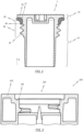
- FIG. 2 shows the plug 1 according to the invention in the non-installed state.
- a plug 1 according to the invention can be used to close and seal an opening 120 of an energy storage system 100, an energy storage module and/or an energy storage cell.
- the plug 1 has a plug head 10 and a plug body 14 formed integrally with the plug head 10.
- a sealing region 30, which is located directly below the plug head 10, and a connecting region 20, which is located directly below the sealing region 30, are arranged on the plug body 14.
- the plug body 14 is at least substantially sleeve-shaped, ie the plug body 14 has an annular cross-section at least in some areas, such that an outer diameter of the plug head 10 is between 10% and 40%, preferably 15% and 40%, particularly preferably between 20% and 30%, larger than an outer diameter of the plug body 14, in particular in an area below the connecting area 20.
- a lower area of the plug body 14, seen in the axial direction A of the plug 1 can be chamfered. This facilitates both the manufacture and the assembly of the plug 1, in particular the insertion of the plug 1 into the opening 120. Such a chamfer is associated with easier demolding during the manufacturing process. This means that costly and complex ejection mechanisms can be avoided. The chamfer can also be used to pre-center the plug 1 during assembly.
- connection region 20 serves to connect the plug 1 according to the invention to an opening 120 in the housing 110, in particular in the housing cover, of the energy storage system 100.
- connection region 20 can have an external thread 22 which engages with a corresponding internal thread of the opening 120.
- connection area 20 is designed as a plug connection. This advantageously facilitates the assembly of the plug 1 according to the invention.
- the connection area 20 can have locking lugs for engaging in a correspondingly designed geometry in the opening 120, such that a positive and/or non-positive connection is created between the plug 1 and the opening 120.
- the sealing area 30 is designed to accommodate a sealing element 32.
- the sealing element 32 already has a shape that is at least substantially different from a circular shape in a non-installed state of the plug 1, which is accompanied by an undeformed state of the sealing element 32.
- the sealing element 32 has a substantially L-shape in cross section.
- a substantially L-shape means, firstly, that the cross section of the sealing element 32 has two legs which enclose an angle which is between 80° and 100°, preferably between 85° and 95°, particularly preferably 90°, and secondly that the edges and/or corners of the sealing element 32 can be rounded or curved.
- the sealing element 32 has in particular a first region which is formed in the direction of a side of the sealing element 32 facing the connection region 20, and a second region on a side of the sealing element 32 facing away from the connection region.
- the sealing element 32 is shaped in such a way that the second region of the sealing element 32 has a larger outer diameter than the first region even when the plug 1 is not installed, or when the sealing element 32 is not deformed. More precisely, the first region of the sealing element 32 extends essentially in the axial direction A of the plug 1, whereas the second region of the sealing element 32 extends outwards essentially in a radial direction of the plug 1, which is perpendicular to the axial direction A of the plug 1.
- essentially in the axial direction A of the plug 1 means that the extension direction differs by less than 10°, preferably less than 5°, particularly preferably less than 3° from the axial direction A of the plug 1.
- first region and the second region do not merge directly into one another, but rather are connected to one another via a transition region.
- This transition region can, for example, have an additional region that extends in a direction opposite to the first region, such that the sealing element 32 forms, for example, a substantially T-shaped cross-section.
- the plug 1 can also have a groove 12 in the sealing area 30 that runs along a circumference of the plug 1 and is designed to accommodate the sealing element 32.
- the sealing element 32 can be molded directly into the groove 12. This advantageously results in a secure, in particular material-locking, connection.
- the sealing element 32 is limited upwards by the plug head 10 and downwards by a circumferential projection 40, as seen in the axial direction A of the plug 1.
- the circumferential projection 40 is arranged between the sealing element 32 and the connecting area 20 and is designed to Sealing element 32 is to be spaced by 2 mm to 6 mm, preferably by 3 mm to 5 mm from the connection region 20, in particular from an uppermost thread of the connection region 20 as seen in the axial direction A of the plug 1.
- the plug can be made of a first plastic material.
- a thermoplastic material such as polyethylene, polypropylene, polyamide, acrylonitrile butadiene styrene, polybutylene terephthalate, polyetherimide, polyimide, polytetrafluoroethylene and/or polyoxymethylene is particularly suitable as the first plastic material.
- the sealing element 32 can be made of a second plastic material which is different from the first plastic material.
- the second plastic material is an elastic material, such as an elastomer, thermoplastic elastomer, silicone, and/or a silicone-like substance.
- the plug according to the invention can be produced simply and inexpensively using a two-component injection molding process. This also ensures a good connection between the plug 1 and the sealing element 32. In particular, when the sealing element 32 is molded onto the plug 1, in particular into the groove 12 of the plug 1, the outermost surface of the plug 1 or the groove 12 can melt, so that a material connection is created between the sealing element 32 and the plug 1.
- the sealing element 32 is further designed such that the sealing element 32 is formed completely around the plug 1.
- sealing element 32 is designed to be rotationally symmetrical, which also reduces costs, since the tool for a symmetrical sealing element 32 is less complex to design.
- the plug 1 according to the invention is based on the finding that it is advantageous if the sealing element 32 is deformed in the installed state of the plug 1 by a force acting completely in the axial direction A of the plug 1.
- This has a particular effect on a reduction in the sealing effect by the "settling" of the connecting elements of the plug 1, namely in that in the installed state of the plug 1 there is a force coupling between the force acting at least partially, in particular completely, in the axial direction A of the plug 1 and a restoring force which is caused by the material of the sealing element 32 on the basis of the force acting at least partially, in particular completely, in the axial direction A of the plug 1.
- a sealing effect of the sealing element 32 can be generated by the force acting entirely in the axial direction A of the plug 1.
- the sealing element 32 is advantageously only spaced from the connection area 20 by the circumferential projection 40. This prevents the plug body 14 from lengthening, which reduces the force.
- FIG. 3 shows the opening 120 receiving the plug 1 according to the invention in a housing 110 of an energy storage system 100.
- a sealing rib 130 is shown, which extends along an inner circumference of the opening 120 receiving the plug 1 in the direction of an exterior of the energy storage system 100.
- This sealing rib 130 is designed to engage with the sealing element 32 of the plug 1 in the installed state of the plug 1.
- the inner circumference of the opening 120 receiving the plug 1 is understood to mean the circumference of a region of the opening 120 receiving the plug body 14. More precisely, the opening 120 has at least two different regions with different diameters.
- the first region corresponds to a depression and is designed to receive the plug head 10.
- the second region has a diameter that is smaller than the diameter of the first region and is designed to receive the plug body 14, in particular the connecting region 20.
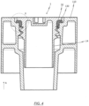
- FIG. 4 shows the plug 1 according to the invention in the installed state, in which the plug 1 is connected to the opening 120 - in this case by way of example via a screw connection. It can be seen that the sealing rib 130 seals the sealing element 32, in particular the second region of the sealing element 32. deformed by a force acting at least substantially in the axial direction A of the plug 1.
- the sealing element 32 By selecting a suitable material for the sealing element 32, in particular by making the sealing element 32 from an elastic material, an advantageous force coupling is created when the plug 1 is installed, i.e. when the sealing element 32 is deformed. Because the sealing rib 130 generates a force acting on the sealing element 32 in the axial direction A of the plug 1, and the sealing element 32 generates a restoring force which acts in the opposite direction to the axial force generated by the sealing rib 130, the sealing effect of the sealing element 32 can be maintained even in the event of high thermal and/or mechanical (dynamic) influences, which could otherwise cause a reduction in both forces, for example by changing the material properties or by generating "settling" movements. "Settling" or “settling” movements is understood to mean a loss of the preload force of the connection.
- FIG. 5 shows the FIG. 4 with a dashed circle marked area X in a detailed view. It can be clearly seen that the sealing element 32 is deformed exclusively in the axial direction A of the plug 1 and in particular not in a radial direction. This advantageously leads to a simple assembly of the plug 1 in the housing.
- plug head 10 is flush with an outer side of the housing 110. This can, for example, prevent the risk of injury from any sharp edges, which increases handling safety.
- the plug 1 can also be used in a housing 120 of an energy storage module or an energy storage cell.
- connection area 20 of the plug 1 can also be designed as a plug connection instead of the external thread 22. This further simplifies the installation of the plug 1 in the opening 120.
- locking lugs arranged on the plug body 14, which are designed to interact with corresponding recesses in the opening 120, could also form a positive connection.
Landscapes
- Chemical & Material Sciences (AREA)
- Chemical Kinetics & Catalysis (AREA)
- Electrochemistry (AREA)
- General Chemical & Material Sciences (AREA)
- Engineering & Computer Science (AREA)
- Aviation & Aerospace Engineering (AREA)
- Manufacturing & Machinery (AREA)
- Filling, Topping-Up Batteries (AREA)
- Gasket Seals (AREA)
- Sealing Battery Cases Or Jackets (AREA)
Applications Claiming Priority (2)
| Application Number | Priority Date | Filing Date | Title |
|---|---|---|---|
| DE102017100049.6A DE102017100049A1 (de) | 2017-01-03 | 2017-01-03 | Stopfen zum verschliessen und abdichten einer öffnung in einem gehäuse eines energiespeichersystems und energiespeichersystem |
| PCT/EP2017/083644 WO2018127410A1 (de) | 2017-01-03 | 2017-12-19 | Stopfen zum verschliessen und abdichten einer öffnung in einem gehäuse eines energiespeichersystems und energiespeichersystem |
Publications (2)
| Publication Number | Publication Date |
|---|---|
| EP3566254A1 EP3566254A1 (de) | 2019-11-13 |
| EP3566254B1 true EP3566254B1 (de) | 2024-10-09 |
Family
ID=61027676
Family Applications (1)
| Application Number | Title | Priority Date | Filing Date |
|---|---|---|---|
| EP17835666.3A Active EP3566254B1 (de) | 2017-01-03 | 2017-12-19 | Stopfen zum verschliessen und abdichten einer öffnung in einem gehäuse eines energiespeichersystems und energiespeichersystem |
Country Status (6)
| Country | Link |
|---|---|
| US (2) | US11894582B2 (es) |
| EP (1) | EP3566254B1 (es) |
| CN (2) | CN110121798A (es) |
| DE (1) | DE102017100049A1 (es) |
| MX (1) | MX2019007992A (es) |
| WO (1) | WO2018127410A1 (es) |
Families Citing this family (2)
| Publication number | Priority date | Publication date | Assignee | Title |
|---|---|---|---|---|
| DE102017100049A1 (de) | 2017-01-03 | 2018-07-05 | Johnson Controls Autobatterie Gmbh & Co. Kgaa | Stopfen zum verschliessen und abdichten einer öffnung in einem gehäuse eines energiespeichersystems und energiespeichersystem |
| DE102018010001A1 (de) * | 2018-12-27 | 2020-07-02 | FRÖTEK Vermögensverwaltung GmbH | Verschlussstopfen einer Batterie |
Citations (2)
| Publication number | Priority date | Publication date | Assignee | Title |
|---|---|---|---|---|
| EP0920063A1 (de) * | 1997-11-19 | 1999-06-02 | Accumulatorenwerke Hoppecke Carl Zoellner & Sohn GmbH & Co. KG | Stopfensystem zum Verschliessen von Zellenöffnungen eines Akkumulators und Akkumulatordeckel zur Verwendung des Stopfensystems |
| EP3394916A1 (en) * | 2015-12-23 | 2018-10-31 | Accumalux | Vent plug for lead acid batteries |
Family Cites Families (16)
| Publication number | Priority date | Publication date | Assignee | Title |
|---|---|---|---|---|
| DE10023747A1 (de) * | 2000-05-15 | 2001-11-22 | Hoppecke Zoellner Sohn Accu | Stopfenanordnung |
| JP2002352787A (ja) * | 2001-05-25 | 2002-12-06 | Japan Storage Battery Co Ltd | 鉛蓄電池 |
| JP2002305021A (ja) * | 2001-04-03 | 2002-10-18 | Japan Storage Battery Co Ltd | 即用式鉛蓄電池の製造方法および保存方法 |
| EP1248315A2 (en) * | 2001-04-03 | 2002-10-09 | Japan Storage Battery Co., Ltd. | Dry-charged lead acid battery and process for the production thereof |
| JP3746214B2 (ja) * | 2001-09-10 | 2006-02-15 | 大電株式会社 | 塞栓構造 |
| DE20218730U1 (de) | 2002-12-03 | 2003-07-03 | Akkumulatorenfabrik Moll GmbH & Co. KG, 96231 Bad Staffelstein | Diagnosesonde für eine Mehrzellen-Batterie |
| DE202005003835U1 (de) * | 2005-03-10 | 2005-05-04 | Abertax Research And Development Ltd. | Entgasungsventil für Batteriezellen |
| CN100409465C (zh) * | 2006-08-09 | 2008-08-06 | 赵恒祥 | 密闭蓄电池封闭塞及其密闭蓄电池 |
| DE102008009864A1 (de) * | 2008-02-19 | 2009-08-20 | FRÖTEK Vermögensverwaltung GmbH | Batterie mit Verschlussstopfen |
| MX2011007505A (es) * | 2009-01-13 | 2011-10-12 | Johnson Controls Tech Co | Cubierta de bateria resistente a derrames y cubierta de ventilacion. |
| WO2010124684A2 (de) * | 2009-04-30 | 2010-11-04 | Vb Autobatterie Gmbh & Co. Kgaa | Ventilstopfen |
| DE102009041417A1 (de) * | 2009-09-16 | 2011-05-19 | Vb Autobatterie Gmbh & Co. Kgaa | Verschlussstopfenanordnung für einen Akkumulator |
| CN103078069B (zh) | 2012-12-29 | 2015-06-10 | 惠州亿纬锂能股份有限公司 | 一种锂离子电池电容器用密封件 |
| CN203815149U (zh) * | 2014-05-16 | 2014-09-10 | 何志雄 | 无卡位双层车载杯密封结构 |
| EP3357107B1 (en) * | 2015-10-01 | 2023-06-07 | Gogoro Inc. | Frame for portable electrical energy storage cells |
| DE102017100049A1 (de) | 2017-01-03 | 2018-07-05 | Johnson Controls Autobatterie Gmbh & Co. Kgaa | Stopfen zum verschliessen und abdichten einer öffnung in einem gehäuse eines energiespeichersystems und energiespeichersystem |
-
2017
- 2017-01-03 DE DE102017100049.6A patent/DE102017100049A1/de not_active Ceased
- 2017-12-19 WO PCT/EP2017/083644 patent/WO2018127410A1/de not_active Ceased
- 2017-12-19 CN CN201780081841.1A patent/CN110121798A/zh active Pending
- 2017-12-19 US US16/474,892 patent/US11894582B2/en active Active
- 2017-12-19 EP EP17835666.3A patent/EP3566254B1/de active Active
- 2017-12-19 CN CN202410333793.2A patent/CN118198611A/zh active Pending
- 2017-12-19 MX MX2019007992A patent/MX2019007992A/es unknown
-
2024
- 2024-02-05 US US18/432,345 patent/US20240243455A1/en active Pending
Patent Citations (2)
| Publication number | Priority date | Publication date | Assignee | Title |
|---|---|---|---|---|
| EP0920063A1 (de) * | 1997-11-19 | 1999-06-02 | Accumulatorenwerke Hoppecke Carl Zoellner & Sohn GmbH & Co. KG | Stopfensystem zum Verschliessen von Zellenöffnungen eines Akkumulators und Akkumulatordeckel zur Verwendung des Stopfensystems |
| EP3394916A1 (en) * | 2015-12-23 | 2018-10-31 | Accumalux | Vent plug for lead acid batteries |
Also Published As
| Publication number | Publication date |
|---|---|
| US20220247054A1 (en) | 2022-08-04 |
| DE102017100049A1 (de) | 2018-07-05 |
| WO2018127410A1 (de) | 2018-07-12 |
| EP3566254A1 (de) | 2019-11-13 |
| CN118198611A (zh) | 2024-06-14 |
| US11894582B2 (en) | 2024-02-06 |
| CN110121798A (zh) | 2019-08-13 |
| US20240243455A1 (en) | 2024-07-18 |
| MX2019007992A (es) | 2019-08-16 |
Similar Documents
| Publication | Publication Date | Title |
|---|---|---|
| EP1960731B1 (de) | Pyrotechnische aktuatoreinheit, verfahren zu deren herstellung sowie gassackmodul mit einer solchen aktuatoreinheit | |
| EP3963217B1 (de) | Befestigungsanordnung mit dämpfungswirkung und bauteilverbindung mit der befestigungsanordnung | |
| WO2017067981A1 (de) | Tülle sowie verfahren zum herstellen einer solchen tülle | |
| DE102014102622A1 (de) | Tank- oder Lademulde | |
| EP3566254B1 (de) | Stopfen zum verschliessen und abdichten einer öffnung in einem gehäuse eines energiespeichersystems und energiespeichersystem | |
| EP2731176B1 (de) | Mischelement sowie Akkumulator mit wenigstens einem Mischelement | |
| EP4128431A1 (de) | Batterieschale, traktionsbatterie, kraftfahrzeug und verfahren zum herstellen einer batterieschale | |
| WO2015110192A1 (de) | Mischelement, sortiment von mischelementen und akkumulator | |
| DE102013102647B4 (de) | Anschlussdurchführung für ein Gehäuse eines elektrischen Bauteils, insbesondere eines Akkumulators, und Verfahren zum Montieren einer Anschlussdurchführung | |
| DE102022200771A1 (de) | Anordnung eines Zellterminals an einem Batteriezellgehäuse sowie ein Verfahren zur Verbindung eines Zellterminals mit ein Batteriezellgehäuse | |
| DE102016210881A1 (de) | Batterie für ein Kraftfahrzeug, Kraftfahrzeug und Verfahren zum Fertigen einer Batterie | |
| WO2011154339A1 (de) | Wasserablaufventil für elektronikgehäuse und elektronikgehäuse mit einem solchen wasserablaufventil | |
| DE202008003886U1 (de) | Vorrichtung zur Realisierung eines trockenen elektrischen Anschlusses eines Kraftfahrzeugschlosses | |
| EP3712976A1 (de) | Batteriemodul und kraftfahrzeug | |
| WO2015197352A1 (de) | Messanordnung zur aufnahme eines sensors | |
| DE102022131180B3 (de) | Batterie für ein Elektrofahrzeug | |
| DE102023128525B3 (de) | Elektrischer Energiespeicher für ein Kraftfahrzeug | |
| EP3209475B1 (de) | Verfahren zur herstellung eines kunststoffbauteils und kunststoffbauteil | |
| EP4401999B1 (de) | Dichtungsanordnung im kühlkreis eines e-achsen-moduls | |
| DE102017004834A1 (de) | Muldenelement für ein Kraftfahrzeug, insbesondere für einen Personenkraftwagen | |
| WO2017076558A1 (de) | Behälter mit versteifungseinrichtung | |
| EP3503307B1 (de) | Elektrisches kupplungsteil | |
| EP2956975B1 (de) | Fixierungselement und akkumulator | |
| DE102014006454A1 (de) | Gassackmodul | |
| DE102011119819A1 (de) | Befestigungsvorrichtung |
Legal Events
| Date | Code | Title | Description |
|---|---|---|---|
| STAA | Information on the status of an ep patent application or granted ep patent |
Free format text: STATUS: UNKNOWN |
|
| STAA | Information on the status of an ep patent application or granted ep patent |
Free format text: STATUS: THE INTERNATIONAL PUBLICATION HAS BEEN MADE |
|
| PUAI | Public reference made under article 153(3) epc to a published international application that has entered the european phase |
Free format text: ORIGINAL CODE: 0009012 |
|
| STAA | Information on the status of an ep patent application or granted ep patent |
Free format text: STATUS: REQUEST FOR EXAMINATION WAS MADE |
|
| 17P | Request for examination filed |
Effective date: 20190703 |
|
| AK | Designated contracting states |
Kind code of ref document: A1 Designated state(s): AL AT BE BG CH CY CZ DE DK EE ES FI FR GB GR HR HU IE IS IT LI LT LU LV MC MK MT NL NO PL PT RO RS SE SI SK SM TR |
|
| AX | Request for extension of the european patent |
Extension state: BA ME |
|
| RIN1 | Information on inventor provided before grant (corrected) |
Inventor name: SCHWAB, JULIUS Inventor name: STAFFELDT, ARMIN Inventor name: KOCH, INGO Inventor name: IDE, BERND |
|
| DAV | Request for validation of the european patent (deleted) | ||
| DAX | Request for extension of the european patent (deleted) | ||
| STAA | Information on the status of an ep patent application or granted ep patent |
Free format text: STATUS: EXAMINATION IS IN PROGRESS |
|
| 17Q | First examination report despatched |
Effective date: 20201216 |
|
| RAP3 | Party data changed (applicant data changed or rights of an application transferred) |
Owner name: CLARIOS GERMANY GMBH & CO. KG |
|
| REG | Reference to a national code |
Ref country code: DE Ref legal event code: R079 Free format text: PREVIOUS MAIN CLASS: H01M0002360000 Ipc: H01M0050645000 Ref country code: DE Ref legal event code: R079 Ref document number: 502017016480 Country of ref document: DE Free format text: PREVIOUS MAIN CLASS: H01M0002360000 Ipc: H01M0050645000 |
|
| GRAP | Despatch of communication of intention to grant a patent |
Free format text: ORIGINAL CODE: EPIDOSNIGR1 |
|
| STAA | Information on the status of an ep patent application or granted ep patent |
Free format text: STATUS: GRANT OF PATENT IS INTENDED |
|
| RIC1 | Information provided on ipc code assigned before grant |
Ipc: H01M 50/645 20210101AFI20240412BHEP |
|
| INTG | Intention to grant announced |
Effective date: 20240430 |
|
| GRAS | Grant fee paid |
Free format text: ORIGINAL CODE: EPIDOSNIGR3 |
|
| GRAA | (expected) grant |
Free format text: ORIGINAL CODE: 0009210 |
|
| STAA | Information on the status of an ep patent application or granted ep patent |
Free format text: STATUS: THE PATENT HAS BEEN GRANTED |
|
| AK | Designated contracting states |
Kind code of ref document: B1 Designated state(s): AL AT BE BG CH CY CZ DE DK EE ES FI FR GB GR HR HU IE IS IT LI LT LU LV MC MK MT NL NO PL PT RO RS SE SI SK SM TR |
|
| REG | Reference to a national code |
Ref country code: CH Ref legal event code: EP |
|
| REG | Reference to a national code |
Ref country code: DE Ref legal event code: R096 Ref document number: 502017016480 Country of ref document: DE |
|
| REG | Reference to a national code |
Ref country code: IE Ref legal event code: FG4D Free format text: LANGUAGE OF EP DOCUMENT: GERMAN |
|
| REG | Reference to a national code |
Ref country code: LT Ref legal event code: MG9D |
|
| REG | Reference to a national code |
Ref country code: NL Ref legal event code: MP Effective date: 20241009 |
|
| P01 | Opt-out of the competence of the unified patent court (upc) registered |
Free format text: CASE NUMBER: APP_2440/2025 Effective date: 20250114 |
|
| PG25 | Lapsed in a contracting state [announced via postgrant information from national office to epo] |
Ref country code: NL Free format text: LAPSE BECAUSE OF FAILURE TO SUBMIT A TRANSLATION OF THE DESCRIPTION OR TO PAY THE FEE WITHIN THE PRESCRIBED TIME-LIMIT Effective date: 20241009 |
|
| PG25 | Lapsed in a contracting state [announced via postgrant information from national office to epo] |
Ref country code: NL Free format text: LAPSE BECAUSE OF FAILURE TO SUBMIT A TRANSLATION OF THE DESCRIPTION OR TO PAY THE FEE WITHIN THE PRESCRIBED TIME-LIMIT Effective date: 20241009 |
|
| PG25 | Lapsed in a contracting state [announced via postgrant information from national office to epo] |
Ref country code: HR Free format text: LAPSE BECAUSE OF FAILURE TO SUBMIT A TRANSLATION OF THE DESCRIPTION OR TO PAY THE FEE WITHIN THE PRESCRIBED TIME-LIMIT Effective date: 20241009 Ref country code: PT Free format text: LAPSE BECAUSE OF FAILURE TO SUBMIT A TRANSLATION OF THE DESCRIPTION OR TO PAY THE FEE WITHIN THE PRESCRIBED TIME-LIMIT Effective date: 20250210 Ref country code: IS Free format text: LAPSE BECAUSE OF FAILURE TO SUBMIT A TRANSLATION OF THE DESCRIPTION OR TO PAY THE FEE WITHIN THE PRESCRIBED TIME-LIMIT Effective date: 20250209 |
|
| PG25 | Lapsed in a contracting state [announced via postgrant information from national office to epo] |
Ref country code: FI Free format text: LAPSE BECAUSE OF FAILURE TO SUBMIT A TRANSLATION OF THE DESCRIPTION OR TO PAY THE FEE WITHIN THE PRESCRIBED TIME-LIMIT Effective date: 20241009 |
|
| PG25 | Lapsed in a contracting state [announced via postgrant information from national office to epo] |
Ref country code: BG Free format text: LAPSE BECAUSE OF FAILURE TO SUBMIT A TRANSLATION OF THE DESCRIPTION OR TO PAY THE FEE WITHIN THE PRESCRIBED TIME-LIMIT Effective date: 20241009 |
|
| PG25 | Lapsed in a contracting state [announced via postgrant information from national office to epo] |
Ref country code: ES Free format text: LAPSE BECAUSE OF FAILURE TO SUBMIT A TRANSLATION OF THE DESCRIPTION OR TO PAY THE FEE WITHIN THE PRESCRIBED TIME-LIMIT Effective date: 20241009 |
|
| PG25 | Lapsed in a contracting state [announced via postgrant information from national office to epo] |
Ref country code: NO Free format text: LAPSE BECAUSE OF FAILURE TO SUBMIT A TRANSLATION OF THE DESCRIPTION OR TO PAY THE FEE WITHIN THE PRESCRIBED TIME-LIMIT Effective date: 20250109 |
|
| PG25 | Lapsed in a contracting state [announced via postgrant information from national office to epo] |
Ref country code: LV Free format text: LAPSE BECAUSE OF FAILURE TO SUBMIT A TRANSLATION OF THE DESCRIPTION OR TO PAY THE FEE WITHIN THE PRESCRIBED TIME-LIMIT Effective date: 20241009 Ref country code: GR Free format text: LAPSE BECAUSE OF FAILURE TO SUBMIT A TRANSLATION OF THE DESCRIPTION OR TO PAY THE FEE WITHIN THE PRESCRIBED TIME-LIMIT Effective date: 20250110 |
|
| PG25 | Lapsed in a contracting state [announced via postgrant information from national office to epo] |
Ref country code: PL Free format text: LAPSE BECAUSE OF FAILURE TO SUBMIT A TRANSLATION OF THE DESCRIPTION OR TO PAY THE FEE WITHIN THE PRESCRIBED TIME-LIMIT Effective date: 20241009 |
|
| PG25 | Lapsed in a contracting state [announced via postgrant information from national office to epo] |
Ref country code: RS Free format text: LAPSE BECAUSE OF FAILURE TO SUBMIT A TRANSLATION OF THE DESCRIPTION OR TO PAY THE FEE WITHIN THE PRESCRIBED TIME-LIMIT Effective date: 20250109 |
|
| PG25 | Lapsed in a contracting state [announced via postgrant information from national office to epo] |
Ref country code: SM Free format text: LAPSE BECAUSE OF FAILURE TO SUBMIT A TRANSLATION OF THE DESCRIPTION OR TO PAY THE FEE WITHIN THE PRESCRIBED TIME-LIMIT Effective date: 20241009 |
|
| PG25 | Lapsed in a contracting state [announced via postgrant information from national office to epo] |
Ref country code: MC Free format text: LAPSE BECAUSE OF FAILURE TO SUBMIT A TRANSLATION OF THE DESCRIPTION OR TO PAY THE FEE WITHIN THE PRESCRIBED TIME-LIMIT Effective date: 20241009 |
|
| PG25 | Lapsed in a contracting state [announced via postgrant information from national office to epo] |
Ref country code: DK Free format text: LAPSE BECAUSE OF FAILURE TO SUBMIT A TRANSLATION OF THE DESCRIPTION OR TO PAY THE FEE WITHIN THE PRESCRIBED TIME-LIMIT Effective date: 20241009 |
|
| REG | Reference to a national code |
Ref country code: DE Ref legal event code: R097 Ref document number: 502017016480 Country of ref document: DE |
|
| PG25 | Lapsed in a contracting state [announced via postgrant information from national office to epo] |
Ref country code: EE Free format text: LAPSE BECAUSE OF FAILURE TO SUBMIT A TRANSLATION OF THE DESCRIPTION OR TO PAY THE FEE WITHIN THE PRESCRIBED TIME-LIMIT Effective date: 20241009 |
|
| PG25 | Lapsed in a contracting state [announced via postgrant information from national office to epo] |
Ref country code: RO Free format text: LAPSE BECAUSE OF FAILURE TO SUBMIT A TRANSLATION OF THE DESCRIPTION OR TO PAY THE FEE WITHIN THE PRESCRIBED TIME-LIMIT Effective date: 20241009 |
|
| PG25 | Lapsed in a contracting state [announced via postgrant information from national office to epo] |
Ref country code: SK Free format text: LAPSE BECAUSE OF FAILURE TO SUBMIT A TRANSLATION OF THE DESCRIPTION OR TO PAY THE FEE WITHIN THE PRESCRIBED TIME-LIMIT Effective date: 20241009 |
|
| PG25 | Lapsed in a contracting state [announced via postgrant information from national office to epo] |
Ref country code: CZ Free format text: LAPSE BECAUSE OF FAILURE TO SUBMIT A TRANSLATION OF THE DESCRIPTION OR TO PAY THE FEE WITHIN THE PRESCRIBED TIME-LIMIT Effective date: 20241009 |
|
| PG25 | Lapsed in a contracting state [announced via postgrant information from national office to epo] |
Ref country code: IT Free format text: LAPSE BECAUSE OF FAILURE TO SUBMIT A TRANSLATION OF THE DESCRIPTION OR TO PAY THE FEE WITHIN THE PRESCRIBED TIME-LIMIT Effective date: 20241009 |
|
| REG | Reference to a national code |
Ref country code: CH Ref legal event code: PL |
|
| PLBE | No opposition filed within time limit |
Free format text: ORIGINAL CODE: 0009261 |
|
| STAA | Information on the status of an ep patent application or granted ep patent |
Free format text: STATUS: NO OPPOSITION FILED WITHIN TIME LIMIT |
|
| PG25 | Lapsed in a contracting state [announced via postgrant information from national office to epo] |
Ref country code: LU Free format text: LAPSE BECAUSE OF NON-PAYMENT OF DUE FEES Effective date: 20241219 |
|
| PG25 | Lapsed in a contracting state [announced via postgrant information from national office to epo] |
Ref country code: SE Free format text: LAPSE BECAUSE OF FAILURE TO SUBMIT A TRANSLATION OF THE DESCRIPTION OR TO PAY THE FEE WITHIN THE PRESCRIBED TIME-LIMIT Effective date: 20241009 |
|
| 26N | No opposition filed |
Effective date: 20250710 |
|
| REG | Reference to a national code |
Ref country code: BE Ref legal event code: MM Effective date: 20241231 |
|
| PG25 | Lapsed in a contracting state [announced via postgrant information from national office to epo] |
Ref country code: BE Free format text: LAPSE BECAUSE OF NON-PAYMENT OF DUE FEES Effective date: 20241231 |
|
| PG25 | Lapsed in a contracting state [announced via postgrant information from national office to epo] |
Ref country code: CH Free format text: LAPSE BECAUSE OF NON-PAYMENT OF DUE FEES Effective date: 20241231 |
|
| PG25 | Lapsed in a contracting state [announced via postgrant information from national office to epo] |
Ref country code: IE Free format text: LAPSE BECAUSE OF NON-PAYMENT OF DUE FEES Effective date: 20241219 |
|
| PGFP | Annual fee paid to national office [announced via postgrant information from national office to epo] |
Ref country code: GB Payment date: 20251229 Year of fee payment: 9 |
|
| PGFP | Annual fee paid to national office [announced via postgrant information from national office to epo] |
Ref country code: FR Payment date: 20251226 Year of fee payment: 9 |
|
| REG | Reference to a national code |
Ref country code: AT Ref legal event code: MM01 Ref document number: 1731616 Country of ref document: AT Kind code of ref document: T Effective date: 20241219 |
|
| PGFP | Annual fee paid to national office [announced via postgrant information from national office to epo] |
Ref country code: DE Payment date: 20251229 Year of fee payment: 9 |
|
| PG25 | Lapsed in a contracting state [announced via postgrant information from national office to epo] |
Ref country code: AT Free format text: LAPSE BECAUSE OF NON-PAYMENT OF DUE FEES Effective date: 20241219 |