EP3565713B1 - Verfahren zum drucken eines 3d-produkts und 3d-druck-vorrichtung - Google Patents
Verfahren zum drucken eines 3d-produkts und 3d-druck-vorrichtung Download PDFInfo
- Publication number
- EP3565713B1 EP3565713B1 EP17700777.0A EP17700777A EP3565713B1 EP 3565713 B1 EP3565713 B1 EP 3565713B1 EP 17700777 A EP17700777 A EP 17700777A EP 3565713 B1 EP3565713 B1 EP 3565713B1
- Authority
- EP
- European Patent Office
- Prior art keywords
- thickness
- layer
- material layer
- zone
- product
- Prior art date
- Legal status (The legal status is an assumption and is not a legal conclusion. Google has not performed a legal analysis and makes no representation as to the accuracy of the status listed.)
- Active
Links
Images


Classifications
-
- B—PERFORMING OPERATIONS; TRANSPORTING
- B29—WORKING OF PLASTICS; WORKING OF SUBSTANCES IN A PLASTIC STATE IN GENERAL
- B29C—SHAPING OR JOINING OF PLASTICS; SHAPING OF MATERIAL IN A PLASTIC STATE, NOT OTHERWISE PROVIDED FOR; AFTER-TREATMENT OF THE SHAPED PRODUCTS, e.g. REPAIRING
- B29C64/00—Additive manufacturing, i.e. manufacturing of three-dimensional [3D] objects by additive deposition, additive agglomeration or additive layering, e.g. by 3D printing, stereolithography or selective laser sintering
- B29C64/10—Processes of additive manufacturing
- B29C64/141—Processes of additive manufacturing using only solid materials
- B29C64/153—Processes of additive manufacturing using only solid materials using layers of powder being selectively joined, e.g. by selective laser sintering or melting
-
- B—PERFORMING OPERATIONS; TRANSPORTING
- B29—WORKING OF PLASTICS; WORKING OF SUBSTANCES IN A PLASTIC STATE IN GENERAL
- B29C—SHAPING OR JOINING OF PLASTICS; SHAPING OF MATERIAL IN A PLASTIC STATE, NOT OTHERWISE PROVIDED FOR; AFTER-TREATMENT OF THE SHAPED PRODUCTS, e.g. REPAIRING
- B29C64/00—Additive manufacturing, i.e. manufacturing of three-dimensional [3D] objects by additive deposition, additive agglomeration or additive layering, e.g. by 3D printing, stereolithography or selective laser sintering
- B29C64/30—Auxiliary operations or equipment
- B29C64/386—Data acquisition or data processing for additive manufacturing
-
- B—PERFORMING OPERATIONS; TRANSPORTING
- B22—CASTING; POWDER METALLURGY
- B22F—WORKING METALLIC POWDER; MANUFACTURE OF ARTICLES FROM METALLIC POWDER; MAKING METALLIC POWDER; APPARATUS OR DEVICES SPECIALLY ADAPTED FOR METALLIC POWDER
- B22F10/00—Additive manufacturing of workpieces or articles from metallic powder
- B22F10/80—Data acquisition or data processing
- B22F10/85—Data acquisition or data processing for controlling or regulating additive manufacturing processes
-
- B—PERFORMING OPERATIONS; TRANSPORTING
- B29—WORKING OF PLASTICS; WORKING OF SUBSTANCES IN A PLASTIC STATE IN GENERAL
- B29C—SHAPING OR JOINING OF PLASTICS; SHAPING OF MATERIAL IN A PLASTIC STATE, NOT OTHERWISE PROVIDED FOR; AFTER-TREATMENT OF THE SHAPED PRODUCTS, e.g. REPAIRING
- B29C64/00—Additive manufacturing, i.e. manufacturing of three-dimensional [3D] objects by additive deposition, additive agglomeration or additive layering, e.g. by 3D printing, stereolithography or selective laser sintering
- B29C64/20—Apparatus for additive manufacturing; Details thereof or accessories therefor
- B29C64/205—Means for applying layers
-
- B—PERFORMING OPERATIONS; TRANSPORTING
- B29—WORKING OF PLASTICS; WORKING OF SUBSTANCES IN A PLASTIC STATE IN GENERAL
- B29C—SHAPING OR JOINING OF PLASTICS; SHAPING OF MATERIAL IN A PLASTIC STATE, NOT OTHERWISE PROVIDED FOR; AFTER-TREATMENT OF THE SHAPED PRODUCTS, e.g. REPAIRING
- B29C64/00—Additive manufacturing, i.e. manufacturing of three-dimensional [3D] objects by additive deposition, additive agglomeration or additive layering, e.g. by 3D printing, stereolithography or selective laser sintering
- B29C64/30—Auxiliary operations or equipment
- B29C64/386—Data acquisition or data processing for additive manufacturing
- B29C64/393—Data acquisition or data processing for additive manufacturing for controlling or regulating additive manufacturing processes
-
- B—PERFORMING OPERATIONS; TRANSPORTING
- B22—CASTING; POWDER METALLURGY
- B22F—WORKING METALLIC POWDER; MANUFACTURE OF ARTICLES FROM METALLIC POWDER; MAKING METALLIC POWDER; APPARATUS OR DEVICES SPECIALLY ADAPTED FOR METALLIC POWDER
- B22F10/00—Additive manufacturing of workpieces or articles from metallic powder
- B22F10/10—Formation of a green body
- B22F10/14—Formation of a green body by jetting of binder onto a bed of metal powder
-
- B—PERFORMING OPERATIONS; TRANSPORTING
- B22—CASTING; POWDER METALLURGY
- B22F—WORKING METALLIC POWDER; MANUFACTURE OF ARTICLES FROM METALLIC POWDER; MAKING METALLIC POWDER; APPARATUS OR DEVICES SPECIALLY ADAPTED FOR METALLIC POWDER
- B22F10/00—Additive manufacturing of workpieces or articles from metallic powder
- B22F10/20—Direct sintering or melting
- B22F10/28—Powder bed fusion, e.g. selective laser melting [SLM] or electron beam melting [EBM]
-
- B—PERFORMING OPERATIONS; TRANSPORTING
- B29—WORKING OF PLASTICS; WORKING OF SUBSTANCES IN A PLASTIC STATE IN GENERAL
- B29K—INDEXING SCHEME ASSOCIATED WITH SUBCLASSES B29B, B29C OR B29D, RELATING TO MOULDING MATERIALS OR TO MATERIALS FOR MOULDS, REINFORCEMENTS, FILLERS OR PREFORMED PARTS, e.g. INSERTS
- B29K2995/00—Properties of moulding materials, reinforcements, fillers, preformed parts or moulds
- B29K2995/0037—Other properties
- B29K2995/0094—Geometrical properties
- B29K2995/0097—Thickness
-
- B—PERFORMING OPERATIONS; TRANSPORTING
- B33—ADDITIVE MANUFACTURING TECHNOLOGY
- B33Y—ADDITIVE MANUFACTURING, i.e. MANUFACTURING OF THREE-DIMENSIONAL [3D] OBJECTS BY ADDITIVE DEPOSITION, ADDITIVE AGGLOMERATION OR ADDITIVE LAYERING, e.g. BY 3D PRINTING, STEREOLITHOGRAPHY OR SELECTIVE LASER SINTERING
- B33Y10/00—Processes of additive manufacturing
-
- B—PERFORMING OPERATIONS; TRANSPORTING
- B33—ADDITIVE MANUFACTURING TECHNOLOGY
- B33Y—ADDITIVE MANUFACTURING, i.e. MANUFACTURING OF THREE-DIMENSIONAL [3D] OBJECTS BY ADDITIVE DEPOSITION, ADDITIVE AGGLOMERATION OR ADDITIVE LAYERING, e.g. BY 3D PRINTING, STEREOLITHOGRAPHY OR SELECTIVE LASER SINTERING
- B33Y30/00—Apparatus for additive manufacturing; Details thereof or accessories therefor
-
- B—PERFORMING OPERATIONS; TRANSPORTING
- B33—ADDITIVE MANUFACTURING TECHNOLOGY
- B33Y—ADDITIVE MANUFACTURING, i.e. MANUFACTURING OF THREE-DIMENSIONAL [3D] OBJECTS BY ADDITIVE DEPOSITION, ADDITIVE AGGLOMERATION OR ADDITIVE LAYERING, e.g. BY 3D PRINTING, STEREOLITHOGRAPHY OR SELECTIVE LASER SINTERING
- B33Y50/00—Data acquisition or data processing for additive manufacturing
- B33Y50/02—Data acquisition or data processing for additive manufacturing for controlling or regulating additive manufacturing processes
-
- B—PERFORMING OPERATIONS; TRANSPORTING
- B33—ADDITIVE MANUFACTURING TECHNOLOGY
- B33Y—ADDITIVE MANUFACTURING, i.e. MANUFACTURING OF THREE-DIMENSIONAL [3D] OBJECTS BY ADDITIVE DEPOSITION, ADDITIVE AGGLOMERATION OR ADDITIVE LAYERING, e.g. BY 3D PRINTING, STEREOLITHOGRAPHY OR SELECTIVE LASER SINTERING
- B33Y80/00—Products made by additive manufacturing
-
- Y—GENERAL TAGGING OF NEW TECHNOLOGICAL DEVELOPMENTS; GENERAL TAGGING OF CROSS-SECTIONAL TECHNOLOGIES SPANNING OVER SEVERAL SECTIONS OF THE IPC; TECHNICAL SUBJECTS COVERED BY FORMER USPC CROSS-REFERENCE ART COLLECTIONS [XRACs] AND DIGESTS
- Y02—TECHNOLOGIES OR APPLICATIONS FOR MITIGATION OR ADAPTATION AGAINST CLIMATE CHANGE
- Y02P—CLIMATE CHANGE MITIGATION TECHNOLOGIES IN THE PRODUCTION OR PROCESSING OF GOODS
- Y02P10/00—Technologies related to metal processing
- Y02P10/25—Process efficiency
Definitions
- Additive manufacturing techniques comprises a process involving putting together or combining materials in order to manufacture 3D products from 3D modeling data, typically a computer-assisted design file, usually layer by layer, as opposed to subtractive manufacturing methodologies, such as traditional machining.
- These elementary volume elements denoted “voxels”, may be created and juxtaposed using a variety of different technical principles, for example by providing drops of photopolymerizable monomers by means of a print head, by selectively photopolymerizing with a source of UV light near the surface of a bath of monomer (stereolithography technique), or by melting polymer powder (selective laser melting (SLM) or selective laser sintering (SLS)) to mention a few.
- SLM selective laser melting
- SLS selective laser sintering
- Additive manufacturing techniques allow the geometry of 3D products to be defined with a great deal of flexibility, but raise a number of problems. In some fields, there is a need to be able to manufacture relatively large and geometrically complicated products and at a low cost. In other fields, care has been taken to manufacture small products even down to micro scale or nano scale.
- the manufacturing time may have a significant impact on the costs.
- To reduce the manufacturing time efforts has been made to print continuous products showing substantially no distinct layers.
- Such manufacturing methods enabling the printing of such 3D products may have the advantage of not being restricted to position the 3D model in a specific way with respect to the printing volume.
- WO 2014/199231 A2 discloses methods involving 2D printing of images on internal substrate layers inside a transparent 3D object.
- WO 01/72502 A1 discloses a method for forming a structural part by a multi-layer deposition technique.
- the material layer thickness can be varied in the process to increase or decrease resolution and manufacturing accuracy.
- US 5 192 469 A discloses a 3D printing method based on a photo-curing polymer building material.
- the MSD value i.e. the minimum solidification depth obtainable with a given material/solidification environment combination.
- the material will be incompletely cured and cannot form an unsupported region of cohesive material, resulting in an inferior strength and definition of the printed object.
- This object is at least partly achieved by means of providing a method according to claim 1.
- This object is at least partly achieved by means of a method for manufacturing a batch of one or more 3D products by additive manufacturing using a layer-by-layer technique.
- the method comprised the steps of; setting a first thickness of a reference layer and forming a first material layer having a second thickness.
- the second thickness is set as a multiple of an integer and the first thickness of the reference layer.
- the method further comprises performing a binding action on the first material layer
- the steps of forming a first material layer having the second thickness and performing a binding action on the first material layer are performed one or more times, thereby forming a first zone in the batch, the first zone having a first resolution.
- the method further involves setting a third thickness, the third thickness being a multiple of an integer and the first thickness of the reference layer, forming a second material layer having the third thickness and performing a binding action on the second material layer.
- the steps of forming a second material layer having the third thickness and performing a binding action on the second material layer are performed one or more times, thereby forming a second zone in the batch, the second zone having a second resolution, the material layer thickness of the second zone being different from the material layer thickness of the first zone.
- the binding action and application of the one or more material layers are repeated until the one or more 3D products are formed.
- the method provides for a flexible method which permits individual control of the resolution for each 3D product in a simple and effective manner.
- the method enables at least two 3D products to be manufactured with different resolution in the same batch, hence it is not necessary to choose between high resolution, i.e. a high number of relatively thin material layers, and a fast manufacturing time which may be achieved by using relatively thick material layers.
- the ratio of binding agent and bulk material may be governed.
- the porosity and the weight of the final 3D products can thus be manipulated. Just as a matter of example, less binding agent may give lighter but more brittle 3D products which sometimes may be acceptable.
- first thickness of the reference layer is T r and the integer is n
- the multiple of the first thickness of the reference layer and the integer is n•T r .
- the setting of a first thickness of a reference layer is preferably done in a control unit for a 3D printing device which may be locally or remotely arranged with respect to the 3D printing device.
- the manufacturing of one or more 3D products may be performed in one single batch, or using a continuous building process.
- a suitable batch size is preferably 1 m 3 or more, such as 2 m 3 or more, 3 m 3 or more, 4 m 3 or more, preferably 5 m 3 or more.
- the integer may be from 1, 2, 3, 4, 5, 6, 7, 8, 9, 10 or more, preferably 1-10, more preferably within the range of 1-10 000, 1-5000, 1-1000, 1-100. In an embodiment, the integer is >1.
- the integer 1 may thus be excluded, or in other words, in an embodiment the integer may be 2, 3, 4, 5, 6, 7, 8, 9, 10 or more, preferably within the range of 2-10, 2-10 000, 2-5000, 2-1000, 2-100.
- a lowest common denominator i.e. the thickness of the reference layer
- the thickness of the reference layer may be selected to be larger than the thinnest material layer possible for the device which is used for manufacturing. In fact this may be preferably as in some aspects; some devices for additive manufacturing may be operated to make large products or products having low demand on resolution, i.e. no need for a high resolution.
- two or more products may be manufactured simultaneously in one batch.
- a first 3D product in the batch may be at least partly formed by material layers having the first thickness
- a second 3D product in the batch may be at least partly formed by material layers having the second thickness. Two or more products may thus be formed having different thickness of the material layers before a binding action is performed.
- the first thickness of the reference layer may be set as a minimal thickness available for a material layer.
- the selected thickness of the reference layer is the smallest available thickness thus defining the highest resolution available for a 3D product in the specific batch.
- the first thickness of the reference layer may be within the range of from 0.001-20, optionally 0.01-20 mm, optionally 0.05-10 mm, optionally 0.05-5 mm, optionally 0.1-1.0 mm.
- the thickness of the reference layer may be selected to be thinner, equal or thicker than the minimum available material layer thickness.
- the material layer may be formed by applying one or more layers of bulk material.
- a material layer refers to the material layer before the binding action has been performed. Hence if measuring for comparative purposes, the measurements and comparisons should be performed before binding action is performed. After every cycle a binding action has been performed at a selected section, a new material layer is thus applied at that selected section.
- the method may be a method for printing at least a first and a second 3D product in a single batch. It has been found that the method is especially advantageous for printing two or more 3D products in one single batch. The method permits the resolution to be controlled for the individual products.
- the binding action may be heat treatment, radiation treatment, light treatment, application of binding agent, application of chemical reactant, or combinations thereof.
- a preferred binding action is to apply binding agent.
- the batch is separated into at least a first and a second zone, whereby in the first zone a material layer having a first thickness is formed and a binding action is subsequently performed, and whereby in the second zone a material layer having the second thickness is formed before a binding action is subsequently performed.
- the method may comprise providing an image on an image displaying unit representative of at least a portion of the printing volume of the batch. Partitioning the image into at least a first and a second zone.
- the first and the second zones each defines boundaries within which zones at least one process parameter governs said partitioned available 3D printing volume.
- the process parameter may in this case be different material layer thicknesses.
- a first material layer thickness is selected, and in a second zone a second material layer is selected, the second thickness being set as a multiple of an integer and the first thickness of the reference layer.
- the same X-Y plane is provided with different multiples.
- different 3D products may be printed having different resolution but still sharing the same X-Y plane. This provides for a very efficient and flexible manufacturing method and device.
- the method may comprise a step to perform a binding action, such as to add binding agent, on a material layer having a first thickness and on a material layer having a second thickness within one and the same run, or 'cycle', such as within one and the same run of the layer bonding unit for depositing binding agent or bind the layer in any other suitable way.
- a binding action such as to add binding agent
- binding agent will be applied on a material layer having a first thickness on a first 3D products and on a material layer having a second thickness on a second 3D product as the depositing unit travels from left to right.
- left to right it is of course possible to go from right to left, i.e. from a first side to an opposing second side.
- Such depositing unit travels back and forth along the X axis.
- the method is a method for controlling the resolution on the one or more 3D products.
- step a) is set as a memorized value, e.g. in a control unit.
- the thickness of the reference layer may be stored and retrieved e.g. each time the device is started, e.g. during a startup phase or upon request by an operator. While the step of applying material layers and performing a binding action are repeated, it is thus not necessary for an operator to set thickness of the reference layer more than once. It may be enough to set the thickness of the reference layer once for each batch for example.
- a first material layer having a second thickness is formed, and a second material layer having a third thickness is formed.
- the third thickness is a multiple of an integer and the first thickness of the reference layer. It may thus be possible to manufacture one or more 3D products in which none of the 3D products has a material layer corresponding to the thickness of the reference layer. This provides flexibility to the manufacturing method and may also enable increased manufacturing speed.
- the first and the second material layers may be formed within one 3D product. It is thus possible to manufacture a single 3D product having two different material layer thicknesses. This provides the possibility to evaluate the impact of different material thicknesses in one batch, and by printing one single 3D product.
- first and the second material layers are formed within in at least two different 3D products. This provides the possibility to evaluate the impact of different material thicknesses and/or different amounts of binding agent as example, in one batch by printing two distinct 3D products.
- the one or more material layer may be formed by a particulate material, and optionally the thickness of said reference layer may be selected based on particle size on the particulate material.
- the particulate material may be a single particulate material or a mixture of different particulate materials.
- step b) forming of the material layer comprises levelling out the material layer.
- the second thickness of the material layer is determined after the material layer has been levelled out.
- the method is applicable on different kinds of material used of forming the material layer. Some material may not need levelling out, while other materials may benefit from being levelled out. Incorporating a levelling out step in which the material layer is smoothen out to provide a flat and uniform surface may enable an improved binding action.
- the thickness of the reference layer may be defined as a levelled out material layer.
- the reference layer may thus be defined as a levelled out material layer.
- the material layer may be levelled out using a fixed blade such as a scraper, and/or, a rotating element such as rotating brush, rotating cylinder, vibrator.
- the objective is further at least partly met by a 3D printing device for manufacturing one or more 3D products in a single batch by additive manufacturing using a layer-by-layer technique according to the appended claim 11.
- the binding action and application of the material layers are repeated until the one or more 3D products are formed.
- the device enables individual control of the resolution for 3D products in a simple and effective manner.
- the device enables at least two 3D products to be manufactured with different resolution in the same batch, hence it is not necessary to choose between high resolution, i.e. a high number of relatively thin material layers, and a fast manufacturing time which may be achieved by using relatively thick material layers.
- the ratio of binding agent and bulk material may be governed.
- the porosity and the weight of the final 3D products can thus be manipulated. Just as a matter of example, less binding agent may give lighter but more brittle 3D products which sometimes may be acceptable. If stronger products are desirable, binding agent may be applied more frequently and/or at higher concentrations.
- the material layer may be formed by one or more bulk material layers, preferably by particulate material.
- a 3D printed product formed by a plurality of material by additive manufacturing using a layer-by-layer technique.
- the material layers have at least a first and a second thickness.
- the second thickness is a multiple of an integer and the first thickness, wherein the integer is >1.
- the invention also relates to a computer program comprising program code means for performing the steps according to the method of the appended claim 1 when the program is run on a control unit of the 3D printing device according to the appended claims 11 -12.
- the disclosure also relates to a computer readable medium carrying a computer program comprising program code means for performing the method of the appended claim 1 when the program product is run on a computer.
- additive manufacturing is herein meant, according to international standard ASTM 2792-12, manufacturing techniques comprising a process involving putting together or combining materials in order to manufacture 3D products from 3D modeling data such as a computer-assisted design file e.g. CAD, usually layer by layer, as opposed to subtractive manufacturing methodologies, such as traditional machining.
- the additive manufacturing method disclosed herein is preferably a binder jetting method in which bonding agent, preferably liquid bonding agent, is selectively deposited onto a particulate material to join the particulate material.
- Other additive manufacturing methods which may benefit from the present disclosure are powder bed fusion, directed energy deposition, material extrusion, vat photopolymerization, material jetting or sheet lamination.
- Embodiments of the present disclosure will be described herein e.g. with reference to glass beads or wood powder as particulate material. It should be noted however that the method or device disclosed herein is not limited to wood powder or glass beads, or even particulate material, as such.
- the method includes that a layer of wood powder is applied onto a support, that binding agent is deposited onto the wood powder layer, whereupon an additional layer of wood powder is applied onto the preceding wood powder layer.
- Such application of wood powder and such deposition of binding agent are alternately repeated a desired number of times, so that wood powder of each layer and of adjacent layers is bonded into a continuous product by means of the binding agent.
- Figure 1a illustrates an example of a model 1 in the form of a doll and Figure 1b schematically illustrates how the model 1 has been divided into horizontally oriented slices 2.
- the model exists as 3D modelling data, e.g. in a CAD file, in a computer program.
- the computer-based model 1 is then used as input data to a control unit of the device according to the disclosure in order to create a substantially similar real 3D product, in the example a doll, consisting of wood powder and binding agent.
- the basics of a suitable layer-by-layer technique are disclosed in the international patent application no. WO2006033621A1 assigned to L3F and will not be described in detail herein.
- the shape of the product is created by means of forming a plurality of layers, preferably more than 10 and usually more than 50, which can exhibit bonded areas of different sizes and different shapes, to overlap each other.
- a product which is 1 meter high is to be created from layers having a thickness of the order of 1 mm, approximately 1000 layers will be required.
- the one or more 3D products are manufactured batch wise, the batch having a printing volume.
- the printing volume is the available volume which can be used to manufacture 3D products. Just as a matter of example, if the printing volume is 1m 3 , a 3D product having a volume of 1m 3 can be printed.
- a method according to the disclosure will enable the manufacturing of one or more 3D products, preferably two or more 3D products, having different layer thickness. The method comprising the steps of setting a first thickness of a reference layer and forming a material layer having a second thickness, the second thickness is set as a multiple of an integer and the said first thickness of the reference layer. A binding action may thereafter be performed on the material layer to form a 3D product.
- the resolution of the one or more 3D products can be manipulated such that the manufacturing method is both more cost effective and faster.
- the doll may thus be manufactured not only in different sizes, but also with different resolution, i.e. with different layer thickness. It is thus also possible to manufacture e.g. two dolls of equal size but having different resolution, i.e. with different layer thickness.
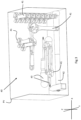
- Figure 2 illustrates a 3D printing device, hereafter only referred to as the device, for manufacturing one or more 3D products in a single batch by means of additive manufacturing using a layer-by-layer technique, in this case a continuous product of wood powder.
- the device includes a layer applying unit 3 for feeding out particulate material, in the shown embodiment wood powder, forming a material layer onto a support 4.
- the device according to embodiments herein may further comprise an optional reinforcing element application unit for application of reinforcing elements such as continuous reinforcing filaments e.g. nylon strings.
- the height or vertical direction corresponds to a Z axis
- the length, or longitudinal direction corresponds to a X axis
- the width, or transverse direction corresponds to a Y axis.
- the Z, X , Y axes are perpendicular to each other.
- the device comprises a receptacle 6 (which, for reasons of clarity, is shown cut off at the front) inside which a base plate 4 also referred to as a support 4, being vertically adjustable along the Z axis and constituting said support, is arranged.
- a base plate 4 also referred to as a support 4
- the support may be fixed and the other units may be adjustable in a vertical direction so as to enable the formation of material layers and the performing of a binding action.
- the layer applying unit and the layer binding unit and optionally a levelling unit if such is present may be vertically adjustable with respect to the support.
- the layer applying unit 3 (in the following called the feeder 3), the depositing unit 5 and an optional unit 7 for levelling the layer and/or for removing excessive wood powder are arranged on a movable carriage 8.
- the feeder 3 and the layer levelling unit 7 are arranged for reciprocating motion along at least the X axis, i.e. in a direction parallel to the base plate 4, for example from a first end 10 to a second end 11 of the receptacle 6 and vice versa.
- the depositing unit 5 which exhibits at least one nozzle 12, preferably a plurality of individual nozzles 12, for deposition of binding agent, should be arranged for displacement along the two axes X, Y, preferably in a plane parallel to the support 4, in order to enable deposition of binding agent onto desired areas.
- a depositing means arranged for displacement along only one axis could be used, but this requires a depositing means which exhibits a large number of separate nozzles arranged along an axis being perpendicular in relation to the displacement axis of the depositing means.
- Other mechanisms for depositing binding agent may be used of course.
- one or more robotic arms may be used such as one or more Cartesian robot arms.
- Different optional arrangements may be used to adapt the thickness of the bulk material layers such as a scraper and/or a rotating brush.
- An excessive bulk material removing unit may also be provided such as a suction and/or blowing device for transporting away excessive bulk material.
- the levelling unit 7 may be operated to level out each applied layer, or to level out after a selected number or layers has been applied.
- the levelling unit may have one leveling cycle for each cycle of the layer applying unit.
- the levelling unit may have one cycle for every second cycle, or more, of the layer applying unit.
- the device further comprises a control unit 19 operatively connected with a display unit 20.
- the display unit 20 may be remotely positioned with respect to the device and connected via wires or in a wireless manner e.g. via Wifi or via other communication protocols, or via a 3G, 4G or 5G network.
- the control unit 19 may include a computer provided with a program for converting one or more 3D models into signals, said signals being used for controlling different components of the device, such as the feeder 3, the depositing unit 5, the levelling unit 7 and the base plate 4. By means of transmitting these signals to motors 30, 31 being arranged for driving the mechanical components, the product according to the invention can be produced in an automatic way.
- the control unit 19 and the display unit 20 may be arranged locally at the device or remotely thereto. A remote location is illustrated by the dashed box.
- binding agent is applied onto selected portions of a bulk material layer in order to form a specific geometry of the 3D product by means of distribution of binding agent.
- the portions where binding agent has been deposited will form the one or more 3D products, while remaining portions of the bulk material layers will remain unbonded, and thus not contribute to the finished one or more 3D products.
- the unbonded material can constitute a support for the 3D products during their manufacture.
- Figure 3 shows an illustration of how the 3D modelling data may be manipulated by a user and as represented on the display unit 20.
- Figure 3 shows a virtual image of the batch representing the printing volume PV of the batch.
- a number of 3D models representing printable 3D products are visualized; a plurality of wrenches 41, a hammer 42 and a plurality of screw drivers 43.
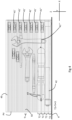
- Figure 4 shows the batch illustrated in figure 3 but with a view along the Y axis. Further illustrated in figure 4 are a plurality of virtual material layers illustrated by the dotted lines 45.
- the dotted lines 45 represent material layers as they could be applied on the support 4, visualized in figure 4 by the line 4'. Supporting walls to the support 4 are not illustrated in figure 4 .
- Via the display unit 20, which functions as an operator interface a user may set a thickness T r , referred to as a first thickness T r , of a reference layer 50.
- the reference layer 50 will thereafter serve as a reference for selecting a suitable resolution to any selected 3D product and/or section of the printing volume PV.
- Material layers may be formed having a second thickness T2.
- the second thickness T2 is selected to be a multiple of an integer and the first thickness of the reference layer.
- the thicknesses of the material layers 45 and the reference layer 50 in figure 4 are not drawn to scale but highly exaggerated for the purpose of clarity, and that in order to have a 3D product resembling a wrench, hammer or screw driver, the material layers should be thinner.
- the thickness T r of the reference layer 50 may for example be selected to be 0.5 mm.
- the thickness of the applied material layers 45 are thus selected so as to be a multiple of 0.5 mm and an integer.
- the integer in the shown example is selected to be 3 as can be gleaned by the dashed and dotted lines within the brackets referred to as T2.
- the integer may be from 1, 2, 3, 4, 5, 6, 7, 8, 9, 10 or more, preferably 1-10, more preferably within the range of 1-10 000, or 1-5000, or 1-1000, or 1-100. In an embodiment, the integer is >1.
- the integer 1 may thus be excluded, or in other words, in an embodiment the integer may be 2, 3, 4, 5, 6, 7, 8, 9, 10 or more, preferably within the range of 2-10, or 2-10 000, or 2-5000, or 2-1000, or 2-100.
- the thickness T r may be the thinnest material layer thickness which the device is able to apply or form using a levelling unit.
- the reference layer is not the thinnest material layer which the device is able to apply.
- the thickness of the reference layer is selected to be larger than the thinnest material layer which the device is able to apply or form using a levelling unit.
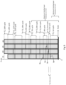
- Figure 5 shows a schematic embodiment with a cross sectional view of a printing volume to illustrate a non-limiting embodiment of the present invention.
- Figure 5 shows the support 4, four 3D products #1, #2, #3, #4 schematically illustrated. The Z and the X axis are also shown.
- the cross section of parts of the printing volume and the four objects #1, #2, #3, #4 illustrates how the binding action may be performed and how the material layers may be applied.
- the material layers formed are illustrated with dashed lines T2 and the applied binding agent Ba is illustrated as a thick line at the selected portion at which it has been applied.
- the thickness of the selected reference layer is illustrated as T r .
- the four 3D products have been printed with different resolution, i.e. layer thickness, in a single batch.
- the 3D printing device permits a minimum binding layer thickness of 0.4 mm, and the layer applying unit and the material permits layers with a thickness of 0.1 mm. In this case it is the binding agent which is the limiting factor and thus determines the available minimum material layer thickness.
- the first 3D product #1 have been printed using the integer 4
- the second 3D product #2 has been printed using the integer 5
- the third 3D product #3 has been printed using the integer 6
- the fourth 3D product #4 has been printed using the integer 15.
- 3D product #1 is formed with a material layer thickness of 4•Tr
- 3D product #2 is formed with a material layer thickness of 5•Tr
- 3D product #3 is formed with a material layer thickness of 6•Tr
- 3D product #4 is formed with a material layer thickness of 15•Tr.
- the thickness of the reference layer is set to 0.1 mm.
- the layer applying unit first applies a material layer having the thickness of four times the reference layer in this case 0.4 mm. Subsequently binding agent Ba is applied on the first 3D product #1 at the selected portion. No binding agent is applied on the other three 3D products.
- the layer applying unit applies a material layer with the same thickness as the reference layer in this case 0.1 mm. Binding agent Ba is subsequently applied only on the second 3D product #2.
- the layer applying unit applies a material layer with the same thickness as the reference layer in this case 0.1 mm. Binding agent Ba is subsequently applied only on the third 3D product #3.
- the layer applying unit applies a material layer with a thickness of two times the reference layer in this case 0.2 mm.
- Binding agent Ba is subsequently applied only on the first 3D product #1.
- the first 3D products has two complete bonded material layers at this stage, while e.g. the fourth 3D product #4 does not yet have one complete material layer yet.
- the layer applying unit applies a material layer with a thickness of two times the reference layer in this case 0.2 mm. Binding agent Ba is subsequently applied only on the second 3D product #2.
- the layer applying unit applies a material layer with a thickness of two times the reference layer in this case 0.2 mm.
- Binding agent Ba is subsequently applied on the first 3D product #1 and on the second 3D product #3.
- the layer applying unit applies a material layer with a thickness of two times the reference layer in this case 0.2 mm.
- Binding agent Ba is subsequently applied on the first 3D product #1 and on the second 3D product #3.
- the layer applying unit applies a material layer with a thickness of three times the reference layer in this case 0.3 mm.
- Binding agent Ba is subsequently applied on the second 3D product #2 and on the fourth 3D product #4.
- the layer applying unit applies a material layer with a thickness of one time the reference layer in this case 0.1 mm. Binding agent Ba is subsequently applied on the first 3D product #1 only.
- the layer applying unit applies a material layer with a thickness of two time the reference layer in this case 0.1 mm. Binding agent Ba is subsequently applied on the third 3D product #3 only.
- the layer applying unit applies a material layer with a thickness of two times the reference layer in this case 0.2 mm.
- Binding agent Ba is subsequently applied on the first 3D product #1 and on the second 3D product #2.
- the layer applying unit applies a material layer with a thickness of four times the reference layer in this case 0.4 mm.
- Binding agent Ba is subsequently applied on the first 3D product #1 and on the third 3D product #3.
- the layer applying unit applies a material layer with a thickness of one time the reference layer in this case 0.1 mm. Binding agent Ba is subsequently applied on the second 3D product #2 only.
- the layer applying unit applies a material layer with a thickness of three times the reference layer in this case 0.3 mm.
- Binding agent Ba is subsequently applied on the first 3D product #1 only.
- the layer applying unit applies a material layer with a thickness of two times the reference layer in this case 0.2 mm.
- Binding agent Ba is subsequently applied on the second 3D product #2, the third 3D product #3 and the fourth 3D product #4.
- the first 3D product #1 now has seven complete and bonded material layers.
- the second 3D product #2 now has six complete and bonded material layers.
- the third 3D product #3 now has five complete and bonded material layers.
- the fourth 3D product #4 now has two complete and bonded material layers.
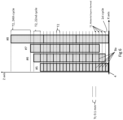
- Figure 6 shows a schematic embodiment with a cross sectional view of a printing volume to illustrate a non-limiting embodiment of the present invention.
- Figure 5 shows the support 4, four 3D products #5, #6, #7, #8 schematically illustrated. The Z and the X axis are also shown.
- the cross section of parts of the printing volume and the four 3D products #5, #6, #7, #8 illustrates how the binding action may be performed and how the material layers may be applied.
- the material layers formed are illustrated with dashed lines T2 and the applied binding agent Ba is illustrated as a thick line at the selected portion at which it has been applied. In figure 6 , only some of the material layers formed and only some of the applied binding agent Ba are indicated for the sake of clarity.
- the thickness of the selected reference layer is illustrated as T r .
- a plurality of 3D products may thus be printing having different resolution but in one single batch.
- the four 3D products have been printed with different resolution, i.e. layer thickness, in a single batch.
- the 3D printing device in the shown embodiment permits a minimum binding layer thickness of 0.1 mm, and the layer applying unit and the material permits layers with a thickness of 0.1 mm.
- the 3D product #5 has an integer of 1
- the 3D product #6 has an integer of 2
- the 3D product #6 has an integer of 3
- the 3D product #8 has an integer of 10.
- material layers having the same thickness as the reference layer Tr is formed.
- a material layer is formed with a thickness of twice the size of the reference layer, i.e. the integer 2 is applied at that stage as this is the first time that this resolution may be applied.
- the last 3D product can be finished by a finalizing material layer having a thickness of 6 times the reference layer.
- the binding agent may saturate each individual material layer, or may penetrate into the preceding layer dependent on how much binding agent that is applied.
- Figure 7 shows a schematic process diagram illustrating an embodiment of the method according to the present disclosure.
- the device uses glass beads as bulk material and a hot melt adhesive as binding agent.
- the glass beads have an average particle size of 0.05 mm.
- a computer forming a control unit comprising a display unit for manufacturing one or more 3D products in one batch by means of additive manufacturing using a layer-by-layer technique is loaded with 3D modelling data for a plurality of 3D products, in this case hammer, a screw driver and a wrench.
- the operator realizes that it is unnecessary to manufacture the 3D products using the highest possible resolution.
- the operator further has the intention to evaluate different properties of the 3D products printed, such as tensional and torsional strength.
- the operator sets the thickness T r of a reference layer.
- the thickness is set to 0.3 mm.
- a suitable resolution on the selected 3D products is determined by selecting suitable integer(s) preferably for each 3D model.
- each 3D model may come with a pre-set integer.
- the manufacturing order of the 3D products is determined.
- the 3D models are positioned in the available printing volume so as to determine when and in which order they should be manufactured.
- the easiest way to do this is to separate the three 3D products with respect to the Z axis (as shown in figure 4 for example) so that they are not arranged in the same plane defined by the Y-X axes.
- order along the Z axis are selected to be; firstly the hammer; secondly the screw driver and thirdly the wrench.
- the data is converted to device readable data.
- the data formed by the above input and terms to the 3D models may be sent to the device control unit which translates the input data to readable data containing instructions for the device.
- the device is now ready for manufacturing the selected 3D products.
- the data may be converted to device readable data before being forwarded to the device.
- a set of integers may be formed which are connected to the 3D models and their positions in the printing volume.
- the set of integers governs how the layer applying unit will form the material layers so that the resolution of the 3D products corresponds to the selected resolution defined by the integers selected.
- the position of the 3D models may be automatically positioned such that a minimum amount of binding actions are required, i.e. a minimum amount of repetitions by the layer bonding unit is required.
- the method may thus comprise that the control unit of the 3D printing device determines a set of integers which sets the thickness of each material layer to be formed.
- the layer applying unit repeatedly applies material layers having a thickness of 0.01 mm across the available printing volume, i.e. the plane defined by the Y-X axes, while the layer bonding unit repeatedly applies binding agent in a pattern corresponding to the specific slice of the 3D models.
- the layer bonding unit instead of applying binding agent subsequently after each material layers has been applied, i.e. every cycle, the layer bonding unit initially applies binding agent every 5 th cycle to print the hammer.
- the layer bonding unit applies binding agent every 3 rd cycle and when the wrench is printed, the layer bonding unit applies binding agent every cycle.
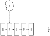
- Figure 8 shows a schematic process diagram illustrating a second embodiment of the method according to the present disclosure.
- the device uses wood powder as bulk material and a wood adhesive as binding agent.
- the wood powder has an average particle size of 0.2 mm.
- a computer forming the display unit for manufacturing one or more 3D products in one batch by means of additive manufacturing using a layer-by-layer technique is loaded with 3D modelling data for a plurality of 3D products, in this case hammer, a screw driver and a wrench.
- a stored thickness value for the reference layer is retrieved from a storage unit.
- the stored thickness value may be set once and thereafter stored in a storage device such as a hard drive on computer. Just as a matter of example, it may optionally be stored and retrieved from a cloud based storage server.
- the stored thickness value of the reference layer is in this case 0.5 mm.
- a suitable resolution on the selected 3D products is determined.
- the manufacturing order of the 3D products are determined.
- the 3D models are positioned in the available printing volume so as to determine when and in which order they should be manufactured. In this case the operator intends to save the amount of bulk material used and to speed up the manufacturing time by reducing the amount of cycles for the layer applying unit.
- the 3D models are selected to share a plane defined by the Y-X axes.
- the 3D products are thus arranged substantially at the same position with respect to the Y axis, diversions due to the shape of the 3D may of course occur.
- the 3D models are however separated with respect to the Y and/or the X axis.
- the order along the Y axis are selected to be; firstly the hammer; secondly the screw driver and thirdly the wrench.
- the data is thereafter sent to the device control unit which translates the input data to readable data containing instructions for the device.
- the 3D products can thereafter automatically be manufactured.
- the layer applying unit repeatedly applies material layers having a thickness of 0.5 mm across the available printing volume, i.e. the plane defined by the Y-X axes, while the layer bonding unit repeatedly applies binding agent in a pattern corresponding to the specific slice of the 3D models or binds the layer in any other suitable way.
- the application of binding agent is controlled so that the correct amount of cycles of material layers are achieved for the specific 3D model.
- the layer bonding unit after each cycle the layer applying unit has applied a material layer having the thickness of the reference layer, the layer bonding unit applies binding agent every 2 nd cycle on the selected area of the hammer.
- the layer bonding unit applies binding agent every 3 rd cycle on the selected area of the screw driver and the layer bonding unit applies binding agent every cycle on the selected area of the wrench. This may be controlled by selectively opening and closing the valves jetting the binding agent from the layer bonding unit.
- a method may comprise one or more of the following steps; at step 110 the control unit process the readable input data derived from the 3D models.
- the layer applying unit applies one or more bulk material layers, e.g. of particulate material, such that a material layer having the thickness of a reference layer is formed multiplied by an integer and an optional levelling step may be performed using a levelling unit.
- one or more bulk material layers e.g. of particulate material
- control unit check if the readable input data demands that binding agent is to be deposited onto selected surfaces of the previously laid material layer based on the set integer for the 3D models and the relative positions of the 3D models in the printing volume with respect to the X, Y, and Z axes.
- binding agent is applied on the selected surfaces.
- the layer applying unit applies another material layer.
- control unit check to see if additional material layers are required. If yes, return to 120.
- step 160 the procedure is terminated and optional post-treatment and actions may be performed such as removing access material, emptying the print volume, performing cleaning and service procedures etc.
- Bulk material is herein meant any material which may be used to form a 3D product by performing a binding action on the bulk material.
- the bulk material is a particulate material.
- the particulate material may be inert particulate material or reactant particulate material.
- a material layer may comprise one or more layers of bulk material.
- inert particulate material may be selected from metals, inert polymers, inert salts, inert organic materials or inert ceramics, or combinations thereof.
- metals examples include aluminium, steel, titanium, iron, alloys, or the like.
- inert polymers include poly (methyl methacrylate), polystyrene, polyamide, polyester, a latex, polyethylene, polypropylene, polyurethane, polyvinyl chloride, polyvinyl acetate, cross-linked polyvinyl pyrrolidone, hydrophilic polyurethane, poly (ethylene terephthalate), thermoplastic urethane, styrene-acrylonitrile copolymer, thermoplastic polyolefin, an epoxy-based polymer, polyether, polyamine, a polyacid, a polycarbonate, a vinyl polymer, an aromatic polyamide, a diene polymer, poly (phenylene oxide), polysiloxane, polynorbornene, polyisoprene, a polyphenylene ether, styrene-butadiene block copolymer, acrylonitrile-butadiene-styrene, high impact polystyrene and copolymers thereof.
- inert salts include sodium carbonate, sodium bicarbonate, sodium borate, sodium chloride, sodium sulfate, potassium sulfate, potassium chloride, magnesium sulfate, magnesium chloride, potassium aluminum sulfate, sodium polyphosphate, sodium acetate, hydrous calcium sulfate, calcium phosphate, sodium silicate, and hydrated lime (Ca (OH) 2).
- inert organic materials include starch, cellulose fibers, wood powder, wax, resin, bone, protein, carbohydrates, sugars, textile fibers and dietary fibers.
- inert ceramics include gypsum, limestone, clay, aluminum oxide, aluminum silicate, calcium silicate, silicon dioxide, titanium dioxide, glass, iron oxide, zinc oxide, magnetite, aluminum hydroxide, magnesium oxide, calcium phosphate, zirconium silicate, silicon carbide, boron nitride, boron carbide and borosilicate.
- a preferred bulk material may be wood powder.
- the expression wood powder as used herein refers to a powder made of a wood material. Different tree species, soft wood or hard wood, such as pine, spruce, birch, larch or others, and different forms of wood originating from branches, trunks, stumps, roots of trees, or in the form of wood waste, such as recycled wood waste, can be used as a starting material for producing the wood powder. Examples of suitable wood materials are wood chips originating from machining of homogenous wood, such as sawdust, cutter shavings, or the like. Wood powder will thus include the same substances as the initial wood does such as lignin, pectin and ash.
- cellulose or cellulose fibers may be derived from wood material but have been treated in a number of process steps, and thus represents another kind of material.
- a cellulose fiber is thus a more refined and elegant material and in some aspects lack substances that wood powder would include.
- cellulose fibers may be natural occurring fibers such as cotton fibers or linen fibers, manufactured fibers from e.g. plants which have been processed into pulp. Examples of plants are crops, wood, leaves or the like. Rayon or viscose fibers are examples of manufactured cellulose fibers.
- wood powder as a bulk material may be advantageous since wood powder can be produced at a low cost, from an easily accessible raw material (wood). The usage of wood powder may even imply that material considered as waste material becomes useful. Furthermore, wood powder is biodegradable and can be used to manufacture biodegradable and thereby environmentally friendly 3D products.
- the particles of the particulate material such as powder e.g. wood powder
- the particle size can be from relatively small, so that the powder obtains a flour-like consistency, to relatively large, implying that the individual particles can be distinguished at a visual inspection.
- the particles of a given powder are substantially of the same size in order to obtain a uniform quality of the final product.
- a particle size in the size interval 0.001-5 mm, and preferably of the order of 0.01-2 mm, can be used when forming the material layers. If, for example, a particle size of 1 mm is chosen, it can be ensured by means of filtration, sometimes referred to as sieve analysis, that the particles in one and the same powder has a size which does not exceed, for example, 1.2 mm, and a size which does not fall below, for example, 0.8 mm.
- the size of the individual particulate matter may be as small as atom size, or nano size.
- atom by atom material layers may be formed using molecular beam epitaxy (MBE) which allows for the vertical stacking of individual atomic layers i.e. the Z-axis, in combination with scanning probe lithography, which uses an extremely sharp tip to move and place individual atoms in a lateral direction, i.e. the X- and Y-axes.
- a Laser particle sizer Analysette 22 NanoTec, by Fritsch may be used. Such device generally has measuring range of 0.01 - 2100 ⁇ m. Standard ISO 13320. Following theory Fraunhofer, Mie. Fraunhofer theory for larger particles when their exact optical parameters are unknown and Mie theory for the smallest particles with known optical parameters. It is possible to select both theories in a FRITSCH MaS control software.
- particle size measurements methods which may be used to determine a particle size are sieve analysis, sedimentation, image particle analysis, microscope counting to mention a few.
- Suitable binding actions may be to add binding agent, to add one or more chemical reactants to form a binding agent on or in the material layer, heat treatment to e.g. melt portions of the material layer such that the material layer is bonded.
- Other binding actions may be radiation treatment, electromagnetic radiation, electron beam, light treatment or combinations thereof.
- binding agents may be used.
- the useful binding agents have in common that they are capable of bonding together the powder, or particles, in the bulk material so that a desired strength of the 3D product can be achieved.
- the binding agent can be water-based, but the binding agent is suitably water resistant. Whether the binding agent should be water resistant or not, however, depends on the 3D product which is to be manufactured and possible post-treatments of the product.
- One suitable binding agent is wood glue, but also a hot melt adhesive, for example a plastic-based one, which is heated during application could be used. Most wood glues which are present on the market have the advantages of being relatively cost efficient and easy to handle, environmentally friendly and particularly suited for bonding wood materials.
- Non-limiting examples of glue are Polyvinyl acetate (PVA) glue, animal glue such as hide glue, Polyurethane glue, Urea-formaldehyde resin adhesives, Resorcinol-formaldehyde resin glue, Cyanoacrylate glue preferably with additive for delayed hardening time.
- PVA Polyvinyl acetate
- animal glue such as hide glue
- Polyurethane glue Urea-formaldehyde resin adhesives
- Resorcinol-formaldehyde resin glue Resorcinol-formaldehyde resin glue
- Cyanoacrylate glue preferably with additive for delayed hardening time.
- the binding agent can also be applied as two or more individual components which together form a binding agent, e.g. via a chemical reaction between the two or more components such as epoxy resin and hardener.
- the binding agent may be formed on the material layer itself or before being applied onto the material layer.
- the concentration or dilution of the binding agent (water content if a water-based binding agent is concerned) can be varied.
- the moisture content of the used bulk material has a certain importance, since the total amount of moisture originating from the powder and the binding agent has to be capable of at least wetting the material to the desired extent in order to enable bonding of selected portions of the bulk material layers.
- the moisture content of the bulk material should also be adapted in order to give the bulk material properties making the bulk material easy to work when being laid out in layers.
- the binding agent may be applied such that each layer is saturated with binding agent, or such that the binding agent sinks into the preceding material layer, or even into preceding material layers. In the latter case, binding agent is applied such that the material layer is bonded together but not saturated.
- binding agent may be applied onto a subsequently applied material layer but yet still penetrate into the preceding one or more material layers. Binding agent may penetrate into two or more such as 2-6 previous material layers. This will provide a 3d product which is continuous in terms of that no, or substantially no, material layers may be identified should the 3D product be cut open and inspected.
- the particulate material constituting the base of the material such as wood powder and, accordingly, the base of the finished 3D product, it is also possible to add small quantities of other substances/materials to the binding agent and/or to the material layer in order to obtain specific properties of the 3D product formed from the particulate material.
- the particulate material such as wood powder, should form at least 50 %, 51 % or more, 60 % or more, 70 % or more, 80 % or more, 90 % or more, 95 % or more of the material layer.
- different substances can be added to the binding agent and/or the material layer, e.g. as a mixture with the particulate material.
- Such an additive is colouring agent, colouring pigment, or the like, in order to give the end product a certain colour.
- colouring agent colouring pigment, or the like
- the finished product can obtain different colours on different visible surfaces.
- reinforcing elements such as reinforcing strings, e.g. nylon strings.
- Flame retardants are generally divided into three groups; minerals, Organohalogen compounds and Organophosphorus compounds. Examples of minerals are; magnesium hydroxide (MDH), aluminium hydroxide (ATH), red phosphorus, boron compounds, huntite and hydromagnesite, and various hydrates.
- MDH magnesium hydroxide
- ATH aluminium hydroxide
- red phosphorus red phosphorus
- boron compounds huntite and hydromagnesite, and various hydrates.
- organohalogen compounds are organochlorines such as chlorendic acid derivatives and chlorinated paraffins; polymeric brominated compounds such as brominated polystyrenes, brominated carbonate oligomers (BCOs), brominated epoxy oligomers (BEOs), tetrabromophthalic anyhydride, tetrabromobisphenol A (TBBPA) and hexabromocyclododecane (HBCD), organobromines such as decabromodiphenyl ether (decaBDE), decabromodiphenyl ethane (a replacement for decaBDE).
- organochlorines such as chlorendic acid derivatives and chlorinated paraffins
- polymeric brominated compounds such as brominated polystyrenes, brominated carbonate oligomers (BCOs), brominated epoxy oligomers (BEOs), tetrabromophthalic anyhydride, tetrabromobisphenol A (
- a flame retardant synergist may further be added to improve the efficiency of the flame retardant, such as antimony trioxide, pentoxide and sodium antimonate.
- organophosphorus compounds are phosphonates such as dimethyl methylphosphonate (DMMP); and phosphinates such as aluminium diethyl phosphinate, triphenyl phosphate (TPP), resorcinol bis(diphenylphosphate) (RDP), bisphenol A diphenyl phosphate (BADP), and tricresyl phosphate (TCP).
- DMMP dimethyl methylphosphonate
- phosphinates such as aluminium diethyl phosphinate, triphenyl phosphate (TPP), resorcinol bis(diphenylphosphate) (RDP), bisphenol A diphenyl phosphate (BADP), and tricresyl phosphate (TCP).
- Flame retardants comprising phosphorus and a halogen may also be used such as and chlorinated organophosphates such as tris(1,3-dichloro-2-propyl)phosphate (chlorinated tris or TDCPP) and tetrakis(2-chlorethyl)dichloroisopentyldiphosphate (V6), tris(2,3-dibromopropyl) phosphate (brominated tris).
- chlorinated organophosphates such as tris(1,3-dichloro-2-propyl)phosphate (chlorinated tris or TDCPP) and tetrakis(2-chlorethyl)dichloroisopentyldiphosphate (V6), tris(2,3-dibromopropyl) phosphate (brominated tris).
Landscapes
- Chemical & Material Sciences (AREA)
- Engineering & Computer Science (AREA)
- Materials Engineering (AREA)
- Physics & Mathematics (AREA)
- Optics & Photonics (AREA)
- Manufacturing & Machinery (AREA)
- Mechanical Engineering (AREA)
Claims (14)
- Verfahren zum Herstellen eines oder mehrerer 3D-Produkte in einer einzigen Charge durch additive Fertigungunter Verwendung einer schichtweisen Technik, das Verfahren umfassend die Schritte;a) Einstellen einer ersten Dicke (Tr) einer Referenzschicht (50);b) Einstellen einer zweiten Dicke (T2) als ein Vielfaches einer ganzen Zahl und der ersten Dicke (Tr) der Referenzschicht (50)c) Ausbilden einer ersten Materialschicht mit der zweiten Dicke (T2);d) Durchführen eines Bindungsvorgangs auf der ersten Materialschicht;wobei die Schritte c) und d) ein oder mehrere Male durchgeführt werden, wodurch eine erste Zone in der Charge ausgebildet wird; unde) Einstellen einer dritten Dicke, wobei die dritte Dicke ein Vielfaches einer ganzen Zahl und der ersten Dicke (Tr) der Referenzschicht (50) ist;f) Ausbilden einer zweiten Materialschicht mit der dritten Dicke;g) Durchführen eines Bindungsvorgangs auf der zweiten Materialschicht;wobei die Schritte f) und g) ein oder mehrere Male durchgeführt werden, wodurch eine zweite Zone in der Charge ausgebildet wird, wobei die erste Zone und die zweite Zone eine gleiche X-Y-Ebene gemeinsam nutzen; und wobei sich die Materialschichtdicke der zweiten Zone von der Materialschichtdicke der ersten Zone unterscheidet, wobei sich eine Auflösung der zweiten Zone von einer Auflösung der ersten Zone unterscheidet.
- Verfahren nach Anspruch 1, wobei die ganze Zahl eine von 1, 2, 3, 4, 5, 6, 7, 8, 9, 10 oder mehr, vorzugsweise 1, 2, 3, 4, 5, 6, 7, 8, 9, 10 oder mehr, stärker bevorzugt innerhalb des Bereichs von 1-10000 oder 1-5000 oder 1-1000 oder 1-100 ist.
- Verfahren nach Anspruch 1 oder 2, wobei ein erstes 3D-Produkt (1) in der Charge zumindest teilweise durch Materialschichten mit der ersten Dicke (Tr) ausgebildet wird, und wobei ein zweites 3D-Produkt in der Charge zumindest teilweise durch Materialschichten mit der zweiten Dicke (T2) ausgebildet wird.
- Verfahren nach einem der vorstehenden Ansprüche, wobei die erste Dicke (Tr) der Referenzschicht (50) als eine minimale Dicke eingestellt ist, die für eine Materialschicht verfügbar ist, oder wobei die erste Dicke (Tr) der Referenzschicht (50) ausgewählt ist, um dünner als eine minimale Dicke zu sein, die für eine Materialschicht verfügbar ist.
- Verfahren nach einem der vorstehenden Ansprüche, wobei die erste Dicke (Tr) der Referenzschicht (50) innerhalb des Bereichs von 0,05 bis 2,0 mm liegt.
- Verfahren nach einem der vorstehenden Ansprüche, wobei das Verfahren ein Verfahren zum Drucken mindestens eines ersten und eines zweiten 3D-Produkts in einer einzigen Charge ist.
- Verfahren nach Anspruch 12, wobei die erste und die zweite Materialschicht innerhalb eines 3D-Produkts ausgebildet werden oder wobei die erste und die zweite Materialschicht innerhalb von mindestens zwei unterschiedlichen 3D-Produkten ausgebildet werden.
- Verfahren nach einem der vorstehenden Ansprüche, wobei in Schritt b) das Ausbilden der Materialschicht ein Nivellieren der Materialschicht umfasst und dass die zweite Dicke der Materialschicht bestimmt wird, nachdem die Materialschicht nivelliert wurde.
- Verfahren nach einem der vorstehenden Ansprüche, wobei die Dicke (Tr) der Referenzschicht (50) als eine nivellierte Materialschicht definiert ist.
- Verfahren nach einem der vorstehenden Ansprüche, wobei ein Satz von ganzen Zahlen ausgebildet wird, wobei der Satz von ganzen Zahlen die Materialschichtdicke definiert, die bei dem Drucken der 3D-Produkte ausgebildet werden soll.
- 3D-Druckvorrichtung zum Herstellen eines oder mehrerer 3D-Produkte in einer einzigen Charge durch additive Fertigung unter Verwendung einer schichtweisen Technik, die 3D-Druckvorrichtung umfassend eine Schichtauftragseinheit (3) zum Auftragen einer oder mehrerer Schichten von Rohmaterial, eine Schichtverbindungseinheit (5) zum Binden eines ausgewählten Abschnitts der aufgebrachten einen oder mehreren Rohmaterialschichten, um ein 3D-Produkt auszubilden, und eine Steuereinheit (19), um mindestens einen Prozessparameter zu steuern,
dadurch gekennzeichnet, dass
die Steuereinheit (19) dazu konfiguriert ist, eine erste Dicke (Tr) einer Referenzschicht (50) einzustellen und um die Charge in eine erste Zone und eine zweite Zone zu trennen, wobei die erste Zone und die zweite Zone eine gleiche X-Y-Ebene gemeinsam nutzen, wobei die 3D-Druckvorrichtung ferner dazu angepasst ist, eine erste Materialschicht mit einer zweiten Dicke (T2) in der ersten Zone auszubilden, wobei die zweite Dicke (T2) als ein Vielfaches einer ganzen Zahl und der ersten Dicke (Tr) der Referenzschicht (50) eingestellt und dazu angepasst ist, eine zweite Materialschicht mit einer dritten Dicke in der zweiten Zone auszubilden, wobei die dritte Dicke als ein Vielfaches einer ganzen Zahl und der ersten Dicke (Tr) der Referenzschicht (50) eingestellt ist; und wobei sich die Materialschichtdicke der zweiten Zone von der Materialschichtdicke der ersten Zone unterscheidet, wobei sich eine Auflösung der zweiten Zone von einer Auflösung der ersten Zone unterscheidet. - 3D-Druckvorrichtung nach Anspruch 11, wobei die Materialschicht durch eine oder mehrere Rohmaterialschichten ausgebildet ist.
- Computerprogramm, umfassend Programmcodemittel zum Durchführen der Schritte nach einem der Ansprüche 1 bis 10, wenn das Programm auf der Steuereinheit der 3D-Druckvorrichtung nach einem der Ansprüche 11 bis 12 ausgeführt wird.
- Computerlesbares Medium, das ein Computerprogramm trägt, umfassend Programmcodemittel zum Durchführen der Schritte nach einem der Ansprüche 1 bis 10, wenn das Programmprodukt auf der Steuereinheit der 3D-Druckvorrichtung nach einem der Ansprüche 11 bis 12 ausgeführt wird.
Priority Applications (1)
| Application Number | Priority Date | Filing Date | Title |
|---|---|---|---|
| PL17700777.0T PL3565713T3 (pl) | 2017-01-03 | 2017-01-03 | Sposób drukowania produktu 3d i urządzenie drukujące 3d |
Applications Claiming Priority (1)
| Application Number | Priority Date | Filing Date | Title |
|---|---|---|---|
| PCT/EP2017/050079 WO2018127275A1 (en) | 2017-01-03 | 2017-01-03 | A method for printing a 3d product and a 3d printing device |
Publications (3)
| Publication Number | Publication Date |
|---|---|
| EP3565713A1 EP3565713A1 (de) | 2019-11-13 |
| EP3565713B1 true EP3565713B1 (de) | 2023-06-07 |
| EP3565713C0 EP3565713C0 (de) | 2023-06-07 |
Family
ID=57851044
Family Applications (1)
| Application Number | Title | Priority Date | Filing Date |
|---|---|---|---|
| EP17700777.0A Active EP3565713B1 (de) | 2017-01-03 | 2017-01-03 | Verfahren zum drucken eines 3d-produkts und 3d-druck-vorrichtung |
Country Status (5)
| Country | Link |
|---|---|
| US (1) | US11602890B2 (de) |
| EP (1) | EP3565713B1 (de) |
| ES (1) | ES2950465T3 (de) |
| PL (1) | PL3565713T3 (de) |
| WO (1) | WO2018127275A1 (de) |
Families Citing this family (8)
| Publication number | Priority date | Publication date | Assignee | Title |
|---|---|---|---|---|
| CN109689123B (zh) * | 2016-09-08 | 2022-08-05 | 卡尔莱布宁医疗技术有限公司 | 具有微结构的颗粒的含钙盐的复合粉末的植入物 |
| US10773310B2 (en) * | 2017-01-31 | 2020-09-15 | General Electric Company | Additive manufacturing system, article, and method of manufacturing an article |
| US11167480B2 (en) * | 2018-10-08 | 2021-11-09 | Sakuu Corporation | Three-dimensional, additive manufacturing system, and a method of manufacturing a three-dimensional object |
| KR102035454B1 (ko) * | 2019-04-24 | 2019-10-22 | 전자부품연구원 | 양자화 오류 문제를 해결하기 위한 3d 프린팅 슬라이싱 방법 |
| EP3925760A3 (de) * | 2020-04-03 | 2022-03-23 | Ricoh Company, Ltd. | Datenausgabegerät, dreidimensionales herstellungssystem und datenausgabeverfahren |
| CN113334773A (zh) * | 2021-06-11 | 2021-09-03 | 电子科技大学 | 一种基于自适应分层的3d打印成型方向多目标优化方法 |
| US20230380380A1 (en) * | 2022-05-26 | 2023-11-30 | Maximilian Lee | Universal drinker base |
| KR102507085B1 (ko) * | 2022-09-13 | 2023-03-07 | 한밭대학교 산학협력단 | 나노 셀룰로오스 섬유를 유효성분으로 포함하는 친환경 3d 프린터용 광경화성 조성물 |
Family Cites Families (9)
| Publication number | Priority date | Publication date | Assignee | Title |
|---|---|---|---|---|
| US5192469A (en) | 1990-10-30 | 1993-03-09 | 3D Systems, Inc. | Simultaneous multiple layer curing in stereolithography |
| ES2230086T3 (es) | 2000-03-24 | 2005-05-01 | Voxeljet Technology Gmbh | Metodo y aparato para fabricar una pieza estructural mediante la tecnica de deposicion multi-capa y moldeo macho fabricado con el metodo. |
| US20130196060A1 (en) * | 2012-01-31 | 2013-08-01 | Xavier Bruch Pla | Forming three dimensional objects |
| DE102012205985A1 (de) * | 2012-04-12 | 2013-10-17 | Maha-Aip Gmbh & Co. Kg | Fahrbahnbelagelemente für einen Rollenprüfstand |
| US20160250809A1 (en) | 2013-05-24 | 2016-09-01 | Looking Glass Hk Ltd. | Method for manufacturing a physical volumetric representation of a virtual three-dimensional object |
| JP6257185B2 (ja) * | 2013-06-28 | 2018-01-10 | シーメット株式会社 | 三次元造形装置及び三次元造形物の造形方法 |
| DE102013021891A1 (de) * | 2013-12-23 | 2015-06-25 | Voxeljet Ag | Vorrichtung und Verfahren mit beschleunigter Verfahrensführung für 3D-Druckverfahren |
| WO2016201326A1 (en) * | 2015-06-10 | 2016-12-15 | Ipg Photonics Corporation | Multiple beam additive manufacturing |
| CN109476872B (zh) * | 2016-10-25 | 2021-02-12 | 惠普发展公司,有限责任合伙企业 | 材料套装 |
-
2017
- 2017-01-03 US US16/472,021 patent/US11602890B2/en active Active
- 2017-01-03 EP EP17700777.0A patent/EP3565713B1/de active Active
- 2017-01-03 WO PCT/EP2017/050079 patent/WO2018127275A1/en not_active Ceased
- 2017-01-03 ES ES17700777T patent/ES2950465T3/es active Active
- 2017-01-03 PL PL17700777.0T patent/PL3565713T3/pl unknown
Also Published As
| Publication number | Publication date |
|---|---|
| US20200016826A1 (en) | 2020-01-16 |
| WO2018127275A1 (en) | 2018-07-12 |
| ES2950465T3 (es) | 2023-10-10 |
| US11602890B2 (en) | 2023-03-14 |
| EP3565713A1 (de) | 2019-11-13 |
| PL3565713T3 (pl) | 2023-09-11 |
| EP3565713C0 (de) | 2023-06-07 |
Similar Documents
| Publication | Publication Date | Title |
|---|---|---|
| EP3565713B1 (de) | Verfahren zum drucken eines 3d-produkts und 3d-druck-vorrichtung | |
| EP3565714B1 (de) | Verfahren zum drucken eines 3d-produkts und 3d-druck-vorrichtung | |
| JP6868657B2 (ja) | 繊維強化加法的製造の方法 | |
| US12552091B2 (en) | Additive manufacturing system using interlinked repeating subunits | |
| US10261499B2 (en) | Device and method of manufacturing customizable three-dimensional objects | |
| KR100650089B1 (ko) | 3차원 인쇄 물질 시스템과 방법 | |
| US20150273769A1 (en) | System, method and apparatus for 3d printing | |
| US8983643B2 (en) | Method for generating and building support structures with deposition-based digital manufacturing systems | |
| EP1527860B1 (de) | Verfahren zur Herstellung dreidimensionaler Gegenstände mittels eines Solid Freeform Verfahrens | |
| CN1572855A (zh) | 包括粘合剂的用于自由成型制造法的粘固剂系统 | |
| EP1791683B1 (de) | Verfahren zur herstellung von produkten auf holzpulverbasis | |
| EP3565707B1 (de) | Verfahren zum drucken eines dreidimensionalen produkts und 3d-drucker | |
| EP3335857A1 (de) | Verfahren und vorrichtung zur schichtweisen herstellung eines objekts | |
| KR101762802B1 (ko) | 3d프린터 출력물을 이용한 조형물 제작방법 | |
| Vikas et al. | Optimization of 3D printing process parameters of poly lactic acid materials by fused deposition modeling process | |
| Odaglia | 3D PRINTING ARCHITECTURE-Open Framework for Binder Jetting in Construction | |
| US8173059B2 (en) | Manufacturing process improvement | |
| Simon | The Effects of Non-Planar 3D Printing on the Strength of Complex Architectural Forms | |
| HK1227811A1 (en) | Device and method of manufacturing customizable three-dimensional objects |
Legal Events
| Date | Code | Title | Description |
|---|---|---|---|
| STAA | Information on the status of an ep patent application or granted ep patent |
Free format text: STATUS: UNKNOWN |
|
| STAA | Information on the status of an ep patent application or granted ep patent |
Free format text: STATUS: THE INTERNATIONAL PUBLICATION HAS BEEN MADE |
|
| PUAI | Public reference made under article 153(3) epc to a published international application that has entered the european phase |
Free format text: ORIGINAL CODE: 0009012 |
|
| STAA | Information on the status of an ep patent application or granted ep patent |
Free format text: STATUS: REQUEST FOR EXAMINATION WAS MADE |
|
| 17P | Request for examination filed |
Effective date: 20190604 |
|
| AK | Designated contracting states |
Kind code of ref document: A1 Designated state(s): AL AT BE BG CH CY CZ DE DK EE ES FI FR GB GR HR HU IE IS IT LI LT LU LV MC MK MT NL NO PL PT RO RS SE SI SK SM TR |
|
| AX | Request for extension of the european patent |
Extension state: BA ME |
|
| DAV | Request for validation of the european patent (deleted) | ||
| DAX | Request for extension of the european patent (deleted) | ||
| STAA | Information on the status of an ep patent application or granted ep patent |
Free format text: STATUS: EXAMINATION IS IN PROGRESS |
|
| 17Q | First examination report despatched |
Effective date: 20210628 |
|
| REG | Reference to a national code |
Ref country code: DE Ref legal event code: R079 Ref document number: 602017069426 Country of ref document: DE Free format text: PREVIOUS MAIN CLASS: B29C0067000000 Ipc: B22F0010800000 |
|
| RIC1 | Information provided on ipc code assigned before grant |
Ipc: B29C 64/393 20170101ALI20221013BHEP Ipc: B29C 64/386 20170101ALI20221013BHEP Ipc: B22F 10/80 20210101AFI20221013BHEP |
|
| GRAP | Despatch of communication of intention to grant a patent |
Free format text: ORIGINAL CODE: EPIDOSNIGR1 |
|
| STAA | Information on the status of an ep patent application or granted ep patent |
Free format text: STATUS: GRANT OF PATENT IS INTENDED |
|
| INTG | Intention to grant announced |
Effective date: 20221201 |
|
| GRAS | Grant fee paid |
Free format text: ORIGINAL CODE: EPIDOSNIGR3 |
|
| GRAA | (expected) grant |
Free format text: ORIGINAL CODE: 0009210 |
|
| STAA | Information on the status of an ep patent application or granted ep patent |
Free format text: STATUS: THE PATENT HAS BEEN GRANTED |
|
| AK | Designated contracting states |
Kind code of ref document: B1 Designated state(s): AL AT BE BG CH CY CZ DE DK EE ES FI FR GB GR HR HU IE IS IT LI LT LU LV MC MK MT NL NO PL PT RO RS SE SI SK SM TR |
|
| REG | Reference to a national code |
Ref country code: GB Ref legal event code: FG4D |
|
| REG | Reference to a national code |
Ref country code: CH Ref legal event code: EP Ref country code: AT Ref legal event code: REF Ref document number: 1573483 Country of ref document: AT Kind code of ref document: T Effective date: 20230615 |
|
| REG | Reference to a national code |
Ref country code: DE Ref legal event code: R096 Ref document number: 602017069426 Country of ref document: DE |
|
| RAP4 | Party data changed (patent owner data changed or rights of a patent transferred) |
Owner name: L3F SWEDEN AB |
|
| U01 | Request for unitary effect filed |
Effective date: 20230630 |
|
| U07 | Unitary effect registered |
Designated state(s): AT BE BG DE DK EE FI FR IT LT LU LV MT NL PT SE SI Effective date: 20230710 |
|
| REG | Reference to a national code |
Ref country code: LT Ref legal event code: MG9D |
|
| REG | Reference to a national code |
Ref country code: ES Ref legal event code: FG2A Ref document number: 2950465 Country of ref document: ES Kind code of ref document: T3 Effective date: 20231010 |
|
| PG25 | Lapsed in a contracting state [announced via postgrant information from national office to epo] |
Ref country code: NO Free format text: LAPSE BECAUSE OF FAILURE TO SUBMIT A TRANSLATION OF THE DESCRIPTION OR TO PAY THE FEE WITHIN THE PRESCRIBED TIME-LIMIT Effective date: 20230907 |
|
| PG25 | Lapsed in a contracting state [announced via postgrant information from national office to epo] |
Ref country code: RS Free format text: LAPSE BECAUSE OF FAILURE TO SUBMIT A TRANSLATION OF THE DESCRIPTION OR TO PAY THE FEE WITHIN THE PRESCRIBED TIME-LIMIT Effective date: 20230607 Ref country code: HR Free format text: LAPSE BECAUSE OF FAILURE TO SUBMIT A TRANSLATION OF THE DESCRIPTION OR TO PAY THE FEE WITHIN THE PRESCRIBED TIME-LIMIT Effective date: 20230607 Ref country code: GR Free format text: LAPSE BECAUSE OF FAILURE TO SUBMIT A TRANSLATION OF THE DESCRIPTION OR TO PAY THE FEE WITHIN THE PRESCRIBED TIME-LIMIT Effective date: 20230908 |
|
| PG25 | Lapsed in a contracting state [announced via postgrant information from national office to epo] |
Ref country code: SK Free format text: LAPSE BECAUSE OF FAILURE TO SUBMIT A TRANSLATION OF THE DESCRIPTION OR TO PAY THE FEE WITHIN THE PRESCRIBED TIME-LIMIT Effective date: 20230607 |
|
| PG25 | Lapsed in a contracting state [announced via postgrant information from national office to epo] |
Ref country code: IS Free format text: LAPSE BECAUSE OF FAILURE TO SUBMIT A TRANSLATION OF THE DESCRIPTION OR TO PAY THE FEE WITHIN THE PRESCRIBED TIME-LIMIT Effective date: 20231007 |
|
| PG25 | Lapsed in a contracting state [announced via postgrant information from national office to epo] |
Ref country code: SM Free format text: LAPSE BECAUSE OF FAILURE TO SUBMIT A TRANSLATION OF THE DESCRIPTION OR TO PAY THE FEE WITHIN THE PRESCRIBED TIME-LIMIT Effective date: 20230607 Ref country code: SK Free format text: LAPSE BECAUSE OF FAILURE TO SUBMIT A TRANSLATION OF THE DESCRIPTION OR TO PAY THE FEE WITHIN THE PRESCRIBED TIME-LIMIT Effective date: 20230607 Ref country code: RO Free format text: LAPSE BECAUSE OF FAILURE TO SUBMIT A TRANSLATION OF THE DESCRIPTION OR TO PAY THE FEE WITHIN THE PRESCRIBED TIME-LIMIT Effective date: 20230607 Ref country code: IS Free format text: LAPSE BECAUSE OF FAILURE TO SUBMIT A TRANSLATION OF THE DESCRIPTION OR TO PAY THE FEE WITHIN THE PRESCRIBED TIME-LIMIT Effective date: 20231007 |
|
| U20 | Renewal fee for the european patent with unitary effect paid |
Year of fee payment: 8 Effective date: 20240117 |
|
| REG | Reference to a national code |
Ref country code: DE Ref legal event code: R097 Ref document number: 602017069426 Country of ref document: DE |
|
| PLBE | No opposition filed within time limit |
Free format text: ORIGINAL CODE: 0009261 |
|
| STAA | Information on the status of an ep patent application or granted ep patent |
Free format text: STATUS: NO OPPOSITION FILED WITHIN TIME LIMIT |
|
| 26N | No opposition filed |
Effective date: 20240308 |
|
| PG25 | Lapsed in a contracting state [announced via postgrant information from national office to epo] |
Ref country code: MC Free format text: LAPSE BECAUSE OF FAILURE TO SUBMIT A TRANSLATION OF THE DESCRIPTION OR TO PAY THE FEE WITHIN THE PRESCRIBED TIME-LIMIT Effective date: 20230607 |
|
| PG25 | Lapsed in a contracting state [announced via postgrant information from national office to epo] |
Ref country code: MC Free format text: LAPSE BECAUSE OF FAILURE TO SUBMIT A TRANSLATION OF THE DESCRIPTION OR TO PAY THE FEE WITHIN THE PRESCRIBED TIME-LIMIT Effective date: 20230607 |
|
| REG | Reference to a national code |
Ref country code: CH Ref legal event code: PL |
|
| PG25 | Lapsed in a contracting state [announced via postgrant information from national office to epo] |
Ref country code: CH Free format text: LAPSE BECAUSE OF NON-PAYMENT OF DUE FEES Effective date: 20240131 |
|
| PG25 | Lapsed in a contracting state [announced via postgrant information from national office to epo] |
Ref country code: CH Free format text: LAPSE BECAUSE OF NON-PAYMENT OF DUE FEES Effective date: 20240131 |
|
| PG25 | Lapsed in a contracting state [announced via postgrant information from national office to epo] |
Ref country code: IE Free format text: LAPSE BECAUSE OF NON-PAYMENT OF DUE FEES Effective date: 20240103 |
|
| PG25 | Lapsed in a contracting state [announced via postgrant information from national office to epo] |
Ref country code: IE Free format text: LAPSE BECAUSE OF NON-PAYMENT OF DUE FEES Effective date: 20240103 |
|
| U20 | Renewal fee for the european patent with unitary effect paid |
Year of fee payment: 9 Effective date: 20250122 |
|
| PGFP | Annual fee paid to national office [announced via postgrant information from national office to epo] |
Ref country code: GB Payment date: 20250120 Year of fee payment: 9 |
|
| PGFP | Annual fee paid to national office [announced via postgrant information from national office to epo] |
Ref country code: TR Payment date: 20250102 Year of fee payment: 9 |
|
| PGFP | Annual fee paid to national office [announced via postgrant information from national office to epo] |
Ref country code: ES Payment date: 20250416 Year of fee payment: 9 |
|
| PG25 | Lapsed in a contracting state [announced via postgrant information from national office to epo] |
Ref country code: CY Free format text: LAPSE BECAUSE OF FAILURE TO SUBMIT A TRANSLATION OF THE DESCRIPTION OR TO PAY THE FEE WITHIN THE PRESCRIBED TIME-LIMIT; INVALID AB INITIO Effective date: 20170103 |
|
| PG25 | Lapsed in a contracting state [announced via postgrant information from national office to epo] |
Ref country code: HU Free format text: LAPSE BECAUSE OF FAILURE TO SUBMIT A TRANSLATION OF THE DESCRIPTION OR TO PAY THE FEE WITHIN THE PRESCRIBED TIME-LIMIT; INVALID AB INITIO Effective date: 20170103 |
|
| PGFP | Annual fee paid to national office [announced via postgrant information from national office to epo] |
Ref country code: CZ Payment date: 20251208 Year of fee payment: 10 |
|
| PGFP | Annual fee paid to national office [announced via postgrant information from national office to epo] |
Ref country code: PL Payment date: 20251207 Year of fee payment: 10 |
|
| U20 | Renewal fee for the european patent with unitary effect paid |
Year of fee payment: 10 Effective date: 20260122 |