EP3565670B1 - Processing system - Google Patents
Processing system Download PDFInfo
- Publication number
- EP3565670B1 EP3565670B1 EP19703956.3A EP19703956A EP3565670B1 EP 3565670 B1 EP3565670 B1 EP 3565670B1 EP 19703956 A EP19703956 A EP 19703956A EP 3565670 B1 EP3565670 B1 EP 3565670B1
- Authority
- EP
- European Patent Office
- Prior art keywords
- flap
- unit
- bearing
- clamping
- conveyor
- Prior art date
- Legal status (The legal status is an assumption and is not a legal conclusion. Google has not performed a legal analysis and makes no representation as to the accuracy of the status listed.)
- Active
Links
- 238000012545 processing Methods 0.000 title claims description 26
- 239000000463 material Substances 0.000 claims description 71
- 239000011435 rock Substances 0.000 claims description 16
- 239000002184 metal Substances 0.000 claims description 13
- 239000004033 plastic Substances 0.000 claims description 9
- 238000007873 sieving Methods 0.000 description 15
- 238000010276 construction Methods 0.000 description 6
- 230000000694 effects Effects 0.000 description 5
- 238000013461 design Methods 0.000 description 4
- 230000010355 oscillation Effects 0.000 description 3
- 238000012216 screening Methods 0.000 description 2
- 230000009471 action Effects 0.000 description 1
- 230000004888 barrier function Effects 0.000 description 1
- 230000008901 benefit Effects 0.000 description 1
- 230000000903 blocking effect Effects 0.000 description 1
- 238000011161 development Methods 0.000 description 1
- 230000005484 gravity Effects 0.000 description 1
- 229910052500 inorganic mineral Inorganic materials 0.000 description 1
- 238000000034 method Methods 0.000 description 1
- 239000011707 mineral Substances 0.000 description 1
- 230000003534 oscillatory effect Effects 0.000 description 1
- 230000008569 process Effects 0.000 description 1
- 238000004064 recycling Methods 0.000 description 1
- 230000000087 stabilizing effect Effects 0.000 description 1
- 239000004575 stone Substances 0.000 description 1
- 230000007704 transition Effects 0.000 description 1
- 238000011144 upstream manufacturing Methods 0.000 description 1
- 238000003466 welding Methods 0.000 description 1
Images


Classifications
-
- B—PERFORMING OPERATIONS; TRANSPORTING
- B02—CRUSHING, PULVERISING, OR DISINTEGRATING; PREPARATORY TREATMENT OF GRAIN FOR MILLING
- B02C—CRUSHING, PULVERISING, OR DISINTEGRATING IN GENERAL; MILLING GRAIN
- B02C21/00—Disintegrating plant with or without drying of the material
- B02C21/02—Transportable disintegrating plant
-
- B—PERFORMING OPERATIONS; TRANSPORTING
- B02—CRUSHING, PULVERISING, OR DISINTEGRATING; PREPARATORY TREATMENT OF GRAIN FOR MILLING
- B02C—CRUSHING, PULVERISING, OR DISINTEGRATING IN GENERAL; MILLING GRAIN
- B02C23/00—Auxiliary methods or auxiliary devices or accessories specially adapted for crushing or disintegrating not provided for in preceding groups or not specially adapted to apparatus covered by a single preceding group
- B02C23/02—Feeding devices
-
- B—PERFORMING OPERATIONS; TRANSPORTING
- B02—CRUSHING, PULVERISING, OR DISINTEGRATING; PREPARATORY TREATMENT OF GRAIN FOR MILLING
- B02C—CRUSHING, PULVERISING, OR DISINTEGRATING IN GENERAL; MILLING GRAIN
- B02C23/00—Auxiliary methods or auxiliary devices or accessories specially adapted for crushing or disintegrating not provided for in preceding groups or not specially adapted to apparatus covered by a single preceding group
- B02C23/08—Separating or sorting of material, associated with crushing or disintegrating
- B02C23/10—Separating or sorting of material, associated with crushing or disintegrating with separator arranged in discharge path of crushing or disintegrating zone
-
- B—PERFORMING OPERATIONS; TRANSPORTING
- B02—CRUSHING, PULVERISING, OR DISINTEGRATING; PREPARATORY TREATMENT OF GRAIN FOR MILLING
- B02C—CRUSHING, PULVERISING, OR DISINTEGRATING IN GENERAL; MILLING GRAIN
- B02C23/00—Auxiliary methods or auxiliary devices or accessories specially adapted for crushing or disintegrating not provided for in preceding groups or not specially adapted to apparatus covered by a single preceding group
- B02C23/08—Separating or sorting of material, associated with crushing or disintegrating
- B02C23/16—Separating or sorting of material, associated with crushing or disintegrating with separator defining termination of crushing or disintegrating zone, e.g. screen denying egress of oversize material
-
- B—PERFORMING OPERATIONS; TRANSPORTING
- B02—CRUSHING, PULVERISING, OR DISINTEGRATING; PREPARATORY TREATMENT OF GRAIN FOR MILLING
- B02C—CRUSHING, PULVERISING, OR DISINTEGRATING IN GENERAL; MILLING GRAIN
- B02C21/00—Disintegrating plant with or without drying of the material
- B02C21/02—Transportable disintegrating plant
- B02C21/026—Transportable disintegrating plant self-propelled
Definitions
- the invention relates to a processing plant, in particular a crushing plant, in particular a rock crusher for natural stone processing and for the recycling of demolition materials, with a filling unit which can be filled with a material to be crushed.
- a sieve unit is arranged in the conveying direction after the filling unit and can be set in oscillatory motion by means of a vibration exciter.
- a first part of the material supplied is fed to a breaking unit via the sieving unit, and a further part is sieved out in the sieving unit.
- the screened-out part of the material is fed to a conveyor unit in a bypass position by means of a flap that can be adjusted about a swivel axis, either past a crushing unit conveyor to a crusher discharge conveyor, or is conveyed out of a working area of the processing system in a conveying position by means of a conveyor device.
- Bearing sections of a bearing are coupled to opposite sides of the flap and are rotatably mounted on the conveyor unit.
- CA1042404 A shows a corresponding processing plant, according to the preamble of claim 1.
- Such crushing plants are used to crush rock material and are used either as mobile or as stationary plants.
- the material to be broken is filled into the system via the filling unit.
- Excavators are usually used for this.
- the material to be shredded is conveyed to the sieving unit by a conveyor.
- the sieve unit can have different designs. Designs are known in which the sieve unit forms a simple conveyor trough which is provided with openings in order to achieve a sieving effect (grate trough). Furthermore, designs are known in the prior art in which a screen deck is used as a circular or elliptical oscillator. One or more additional screens are installed below a conveyor trough. The rock material is fed to a crushing unit via a conveyor.
- the crushing unit can be a jaw crusher.
- the upstream unit grate gutter or sieve
- part of the supplied material is screened out, this screened-out fraction is bypassed in the bypass unit so that it does not burden the crusher.
- Sidebands are usually used for this.
- the user now has the option of choosing whether to drive one or the other mode of operation. To do this, he must adjust the adjustable flap of the conveyor to either the bypass position or the conveyor position.
- the flap must be adjustable, in particular rotatable between the swivel positions (the bypass position and the conveying position), on the conveying unit.
- bearing receptacles are provided on the conveyor unit in the prior art, in which the bearing sections of the flap are rotatably mounted.
- the bearing has a play in the range of one or more 1/10 mm.
- the vibrations of the flap together with the sieve unit during operation the bearings can deflect over time.
- it has proven to be problematic to securely and reliably fix the flap in one of the pivot positions relative to the conveyor unit over a longer period of time.
- screw connections for fixing the flap in one of the swivel positions often become loose.
- the present invention is therefore based on the object of improving the availability and operational reliability of the processing plant, in particular with regard to the adjustable flap that swings together with the sieve unit.
- At least one releasable clamping section is assigned to at least one of the bearing sections, which has a clamping effect on the assigned bearing section and fixes it in a pivoting position of the flap relative to the conveyor unit, so that the Flap is rotatably held in the pivot position relative to the conveyor unit.
- At least one of the clamping sections assigned to a bearing section is held in a rotationally fixed manner on the conveyor unit, so that the clamping section or sections assigned to a bearing section form a bearing seat for the bearing section.
- the clamping section acts in a clamping manner on the at least one bearing section
- the bearing section is held in a rotationally secured manner by means of frictional engagement, so that the flap is fixed relative to the conveying unit in the current pivot position about the pivot axis.
- the at least one with the least one clamping section provided bearing then no longer has any bearing play and a knocking out of the bearing during the operational use of the processing plant is reliably and reliably prevented.
- the clamping of the at least one bearing section by the at least one releasable clamping section preferably acts on the bearing section in the radial direction from the outside.
- the clamping it would also be conceivable for the clamping to act on the bearing section in the radial direction from the inside.
- the bearing section could, for example, have a cylindrical opening inside, in which the at least one clamping section is arranged.
- a single clamping section for example in the form of a clamping ring, can be assigned to a bearing section, the inner circumference of which can be reduced by means of suitable clamping means, for example in the form of at least one screw, in order to generate the clamping action acting on the bearing section, so that the clamping section can also be used its inner circumference clampingly engages around the outer circumference of the bearing section.
- suitable clamping means for example in the form of screws, which act between adjacent clamping sections, the inner circumference of the clamping ring can be reduced and the clamping sections can be clamped around the outer circumference of the bearing section.
- the clamping forces of the at least one clamping section preferably act on the associated bearing section in a plane that is perpendicular to the pivot axis of the flap. It has been shown that such a clamping securing of the flap relative to the delivery unit is considerably more robust with respect to oscillations and vibrations than the previously used securing devices, for example by means of pure screw connections and positive locking.
- the flap has a profile section, the central axis of which forms the pivot axis of the flap and the bearing sections of the bearing are coupled to the longitudinal ends thereof.
- the profile section can be broken through by longitudinal struts be passed through, which form a support structure for stabilizing and / or stiffening the flap.
- the profile section can be fixed to the longitudinal struts, for example welded.
- the bearing sections are welded to the ends of the profile section or fastened in a rotationally fixed manner in some other way.
- the adjustable conveyor unit has two mutually spaced fastening sections, between which the flap is pivotally held, the fastening sections being fastened to the sieve unit. It can in particular be provided here that the fastening sections are fastened to opposite side walls of the sieve unit. Bushings for the bearing sections of the flap can be formed in the fastening sections.
- the fastening sections of the conveyor unit are preferably attached to opposite side walls of the sieve unit via flange sections which are formed on the one hand on the side walls of the sieve unit and on the other hand on the fastening sections.
- the corresponding flange sections are simply brought into contact and fastened to one another using suitable fastening means, for example using screws and nuts. Flanging the fastening sections on the side walls of the sieve unit enables particularly simple assembly and disassembly or particularly simple exchange of the conveyor unit.
- the at least one bearing section be assigned two clamping sections, a first clamping section being fastened on the outside to one of the fastening sections and designed to receive the bearing section.
- the other clamping section is arranged on a side of the bearing section opposite the first clamping section and can be detachably fastened to the first clamping section, so that the bearing section can be fixed in a pivoted position of the flap relative to the conveyor unit and the flap in the pivoted position relative to the conveyor unit is held against rotation.
- the clamping sections assigned to a bearing section are preferably arranged on the outside of the fastening sections, so that they can be easily reached by a user from the outside in order to be able to quickly and easily generate or release the clamping effect of the clamping sections on the assigned bearing section.
- the respective clamping sections assigned to one of the bearing sections can be detachably fastened to one another in order to grip around the bearing section arranged therebetween.
- fasten the clamping sections to one another by means of screws, so that the bearing section is clamped between the clamping sections by tightening the screws, so that the flap is held in a rotationally fixed manner in the pivoted position relative to the conveyor unit.
- the at least one bearing section has a substantially circular outer circumference and the at least one clamping section has a circular arc-shaped inner circumference.
- the inner circumference of the clamping sections can also comprise a plurality of flat segments which, strung together, form an approximately circular arc-shaped inner circumference. The same applies to the outer circumference of the bearing section. In this way, the clamping section or sections can be clamped over a large area on the respectively associated bearing section.
- the flap in a desired pivoting position relative to the delivery unit in addition to the clamping sections in a different manner, for example by means of a positive fit.
- it can additionally be provided, in order to hold the flap on the vibrating sieve unit securely in the respective pivoted position, that at least one locking section with at least one locking receptacle is attached to the flap.
- the at least one locking section is rotatably connected to the flap.
- the locking section or sections can be fixed in the bypass position and / or the conveying position on fixed fastening elements by means of a positive fit.
- a preferred embodiment of the invention is such that the flap has a central region, which is followed by bends on both sides laterally transverse to the conveying direction, and that the sieve unit has a conveying trough which is formed, at least in regions, by a limp component, for example a band made of rubber or plastic to which the flap is placed with its underside in the bypass position.
- a limp component for example a band made of rubber or plastic to which the flap is placed with its underside in the bypass position.
- the conveyor trough can be easily shaped into a trough-like shape.
- the conveyor trough collects the goods to be transported in the middle of the conveyor trough and directs it to the flap.
- the flap with its central area and its laterally connected angled sections, approximates the groove-shaped geometry of the limp component and thus ensures that the screened material is clearly derived.
- the flap is underpinned by means of a support structure which is formed by longitudinal struts and cross struts, the flap is of a particularly light and stable construction.
- a particularly preferred embodiment of the invention provides that the adjustable conveying unit has a conveying element in the conveying direction behind the flap, which in the bypass position of the flap connects to the conveying area of the flap.
- the conveying element is underpinned by means of a supporting structure which is formed by one or more support struts (e.g. longitudinal struts and transverse struts), the conveying element is of a light and stable construction.
- a supporting structure which is formed by one or more support struts (e.g. longitudinal struts and transverse struts)
- the conveying element is of a light and stable construction.
- the flap and / or the conveying element have a sheet metal section which is preferably underpinned by the supporting structure on its underside.
- the flap and / or the conveying element it would be conceivable for the flap and / or the conveying element to have a material section made of a pliable material, in particular rubber or plastic, which is preferably underpinned by the supporting structure on its underside.
- the material section made of flexible material has the particular advantage that, due to the oscillations and vibrations of the conveying unit and the flap or conveying element that moves with it, it can be set into particularly strong and abrupt vibrations, which effectively fix the fine screened material on the surface of the flap or the conveying element prevent.
- the limp material section can rest directly on the supporting structure or on the sheet metal section applied thereon.
- At least one stiffening element is present in or on the material section.
- the flap or the conveying element can be brought into the desired shape and held in this shape by the stiffening element or elements.
- the center area and the angled portions adjoining it laterally can be formed by the support structure and / or the stiffening element or elements in the flap or the conveying element, so that they emulate the trough-like geometry of the conveying trough.
- a further preferred embodiment of the invention is such that the flap and / or the conveying element has a central region, to which bends are connected on both sides laterally transversely to the conveying direction, the material section consisting of a flexible material of the flap or the conveying element in the manner of a drum covering on the outside of the bends along the Direction of conveyance is clamped.
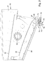
- FIG 1 shows a mobile crushing plant 10, as is typically used for crushing rock material or other mineral material.
- This Mobile crushing plant 10 has a machine chassis which is supported by two running gear designed as chain drives.
- the crushing plant 10 is equipped with a filling unit 20, which is usually designed as a funnel-shaped feed unit.
- the crushing plant 10 can be filled with the material to be shredded via this filling unit 20.
- the filling unit 20 has a conveyor on the bottom, in particular a grate gutter or, as in the present case, a conveyor belt.
- the material to be comminuted is conveyed to a sieving unit 30 via this conveying device.
- a vibration exciter 38 is assigned to the sieving unit 30 and can be designed as an eccentric drive. With this vibration exciter 38, the sieving unit 30 can be set in vibration in order to subject the conveyed material to a sieving process.
- the vibration exciter 38 not only vibrates the sieving unit 30 for sieving purposes, but in connection with the inclined arrangement of the individual sieve decks, a transport effect is also achieved, as in the case of a vibration conveyor.
- the crushing unit 40 is designed in the form of a jaw crusher. This crushing unit 40 has two crushing jaws which form a converging gap. The material to be shredded is conveyed into this gap area.
- the crushing unit 40 has a fixed crushing jaw and a movable crushing jaw. The movable crushing jaw is driven by an eccentric drive 41.
- the coarse rock material is broken in the converging gap. At the bottom, the broken and crushed rock material leaves the crushing unit 40 and falls onto a crusher discharge conveyor 60 due to gravity.
- the crusher discharge conveyor 60 is designed as an endlessly rotating conveyor belt. The crushed rock material is discharged via the crusher discharge conveyor 60 and piled up next to the crushing plant 10.
- the material coming from the filling unit 20 is passed through a sieve 32 (eg top sieve deck) in the sieving unit 30.
- a sieve 32 eg top sieve deck
- rock parts which, because of their size, do not have to be sent through the crushing unit 40, since they already have a size which corresponds approximately to the size of the rock which is broken by the crushing unit 40.
- a part of this sifted rock fraction is fed directly onto the crusher discharge conveyor 60, namely in the bypass past the crusher unit 40.
- Below the sieve 32 there is now another sieve deck 34 in the sieving unit 30. This screen deck 34 screens a further, fine fraction from the material that has already been screened.
- the sieve unit 30 has two side walls 31 which are arranged at a distance from one another.
- the conveying area for the rock material is formed between the two side walls 31.
- the illustration shows that at least one of the side walls 31 has a receptacle 33 for the vibration exciter 38.
- the vibration energy of the vibration exciter 38 can thus be introduced into the side wall 31.
- a different arrangement of the vibration exciter 38 is also conceivable, but it should be provided that the vibration energy from the vibration exciter 38 is introduced into the sieving unit 30 so that the sieving unit 30 vibrates with the frequency and amplitude of the vibration exciter 38.
- the sieve 32 is held between the two side walls 31 in the upper region of the sieve unit 30.
- the sieve deck 34 is arranged below the sieve 32.
- a conveying area results between the screen 32 and the screen deck 34.
- a conveying area is delimited above the sieve 32 by means of the two side walls 31 and the sieve 32.
- a further conveying area results below the screen deck 34.
- This conveyor area is delimited on the bottom side by a conveyor trough 36.
- the conveyor trough 36 can be designed as a limp component, for example made of rubber or plastic, the longitudinal extent of the conveyor trough 36 extending from the left side of the sieving unit 30 to the adjustable conveyor unit 70.
- the screen deck 34 can be extended by means of a discharge surface 35.
- the discharge surface 35 adjoins the screen deck 34 in the conveying direction in the form of a descending step, so that no barrier arises in the conveying direction.
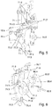
- the adjustable conveyor unit 70 has a flap 72 and a conveyor element 76.
- the flap 72 can be pivoted about a pivot axis 74.1.
- an operating position is shown in which the flap 72 is in a pivoted conveying position.
- the fine fraction fraction screened out from the screen deck 34 is fed onto the discharge belt 50 by means of the flap 72.
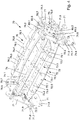
- Figure 3 shows a further operating position of the flap 72, which represents the bypass position. In this pivoted position, the screened fine rock material coming from the conveyor trough 36 is guided onto the conveyor element 76 via the flap 72. The fine rock material then falls from the conveying element 76 onto the crusher discharge conveyor 60.
- the side walls 31 have screw receptacles 37 in the region of the adjustable conveyor unit 70. These are used for fastening the adjustable conveyor unit 70 to the side walls 31 by means of fastening screws 71.6.
- the adjustable conveyor unit 70 can thus be attached to the sieve unit 30.
- the conveyor unit 70 is preferably flanged to the sieve unit 30 by means of flange sections, as will be explained in more detail below.
- the adjustable conveyor unit 70 has two lateral fastening sections 71, which can be designed as sheet metal sections. Both the flap 72 and the conveying element 76 are arranged between the two fastening sections 71.
- the conveyor unit 70 is flanged to the sieve unit 30.
- flange sections 71.7, 71.8 are formed on the opposite side walls 31 of the sieve unit 30 and on the fastening sections 71 of the conveyor unit 70.
- the flange sections 71.7, 71.8 are in detail in the Figures 5 and 6 shown.
- the flap 72 can be formed by a sheet metal section 72.4 as a stamped and bent part. It has a central region 72.1, to which bends 72.2 are connected on both sides. Facing the center area 72.1, the bends 72.2 have bends 72.3. A trough-shaped geometry of the conveying trough 36 is simulated via the laterally set bends 72.2 and the central region 72.1.
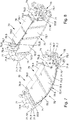
- a support structure 73 is arranged below the flap 72. This support structure 73 has interconnected longitudinal struts 73.1 and cross struts 73.2, 73.3. The flap 72 is underpinned with the support structure 73, so that a stable, lightweight construction is realized.
- a material section 72.5 made of a pliable material for example in the form of a material web made of rubber or plastic.
- This embodiment is, for example, in the Figures 5 and 7 to 10 shown.
- the material section 72.5 can be clamped in the manner of a drum covering on the outer sides of the folds 72.3, so that the material section 72.5, especially in the middle area 72.1 and in the area of the bends 72.2, can be set into particularly strong vibrations when the conveyor unit 70 is together with the sieve unit 30 swings in order to prevent clumping and jamming of the conveyed material arranged thereon.
- the support structure 73 it is also conceivable that at least one stiffening element (not shown) is present in or on the material section 72.5.
- the stiffening element or elements can be made of plastic or metal, for example.
- the flap 72 can be brought into the desired shape and held in this shape by the stiffening element or elements.
- the central region 72.1 and the bends 72.2 which adjoin it laterally can be formed by the support structure 73 and / or the stiffening element or elements in the flap 72, so that they emulate the trough-like geometry of the conveyor trough 36.
- the longitudinal struts 73.1 can have openings through which a profile section 74 is passed.
- the profile section 74 can be fixed to the longitudinal struts 73.1, for example welded.
- the profile section 74 forms with its central longitudinal axis the pivot axis 74.1 of the flap 72.
- bearing sections 75.1 of a bearing 75 are attached to the profile section 74, as is the case here Figure 5 reveals.
- the bearing sections 75.1 can, like shown to be formed by circular disks.
- the bearing sections 75.1 are welded to the ends of the profile section 74 or fastened in a rotationally fixed manner in some other way.
- Locking sections 77.1, 77.2 with locking receptacle 77.3 can be attached either to the bearing sections 75.1 or the support structure 73 or the flap 72.
- each of the bearing sections 75.1 is assigned two clamping sections 80.1, 80.2.
- clamping sections 80.1, 80.2 are held together by means of screws 80.3 and nuts 80.4. If the screws 80.3 or nuts 80.4 are loosened to such an extent that the clamping sections 80.1, 80.2 are held together, but their inner circumference does not abut the outer circumference of the bearing sections 75.1, the clamping sections 80.1, 80.2 are located in a so-called. Bearing position and form inventory for the warehouse sections 75.1.
- the flap 72 can be rotated about the pivot axis 74.1 into one of the pivot positions.
- the clamping sections 80.1, 80.2 reach a securing position in which an inner circumference formed by the clamping sections 80.1, 80.2 is reduced, so that the clamping sections 80.1, 80.2 have a clamping effect on the bearing sections 75.1 and the flap 72 in the swivel position relative to the conveyor unit 70.
- the clamping sections 80.1, 80.2 thus form bearing mounts with adjustable bearing play.
- the bearing play can be reduced to a minimum in the securing position, so that knocking out of the bearings 75 during the operational use of the crushing plant 10 is practically impossible.
- an additional securing of the flap 72 can be provided.
- the additional securing takes place, for example, by using positioning elements 71.5 which are brought into engagement with the locking receptacles 77.3 in the respective pivoted position.
- the positioning elements 71.5 are designed as fastening screws which are inserted through screw receptacles 71.3, 71.4 of the fastening sections 71 and are screwed into the locking receptacles 77.3 designed as threaded receptacles.
- one or more, preferably two, positioning elements 71.5 secure the assignment of the flap 72 to the fastening sections 71 for each swivel position.
- the bearing sections 75.1 can be fixed by means of the releasable clamping sections 80.1, 80.2 in a pivoted position of the flap 72 relative to the conveyor unit 70 or the fastening sections 71, so that the flap 72 is held in a rotationally fixed manner relative to the conveyor unit 70.
- additional securing of the bearing sections 75.1 by means of the locking sections 77.1, 77.2 with the locking receptacles 77.3 and the positioning elements 71.5 can be dispensed with.
- each of the bearing sections 75.1 is assigned two clamping sections 80.1, 80.2, a first clamping section 80.1 of a bearing 75 being fastened to one of the fastening sections 71 and designed to receive the bearing section 75.1, and the other clamping section 80.2 on one of the First clamping section 80.1 opposite side of the bearing section 75.1 is arranged and releasably attachable to the first clamping section 75.1, so that the bearing section 75.1 can be clamped between the two clamping sections 80.1, 80.2 in their securing position.
- the bearing section 75.1 is in a pivoted position of the flap 72 relative to the Conveyor unit 70 can be fixed and the flap 72 is rotatably held in the pivoting position relative to the conveyor unit 70.
- This clamping securing of the flap 72 relative to the fastening sections 71 has proven to be particularly suitable for the large vibrations occurring during the operation of the crushing plant 10.
- the first clamping section 80.1 is fastened to the fastening section 71, for example by means of welding.
- the second clamping section 80.2 can, for example, be detachably fastened to the first clamping section 80.1 by means of the screws 80.3.
- the screws 80.3 can be passed through corresponding openings in the clamping sections 80.1, 80.2 and secured with the nuts 80.4.
- a distance between the clamping sections 80.1, 80.2 can be reduced in the manner of brackets or clamps. In this way, the bearing sections 75.1 can be clamped between the clamping sections 80.1, 80.2.
- the bearing sections 75.1 have a substantially circular outer circumference and the clamping sections 80.1, 80.2 each have a circular arc-shaped inner circumference.
- the inner circumference of the clamping sections 80.1, 80.2 can also comprise a plurality of flat segments which, strung together, form an approximately circular arc-shaped inner circumference. In this way, the clamping sections 80.1, 80.2 can rest on the bearing sections 75.1 over a large area.
- At least one of the bearing sections 75.1 has an actuating element 75.2, which is non-rotatably connected to the bearing section 75.1 and thus to the flap 72.
- the actuating element 75.2 can be formed, for example, by a hexagon.
- the actuating element 75.2 can be accessed with a tool.
- the actuating element 75.2 can be adjusted with the tool and with it the flap 72 in order to pivot it between the bypass position and the conveying position.
- the conveying element 76 is also fastened to the two fastening sections 71.
- the conveying element 76 can consist of a sheet metal section 78.8 as a stamped and bent part be made. It has a central region 76.1, to which bends 76.2 are connected laterally. Facing the central area 76.1, bends 76.3 are bent away from the bends 76.2.
- the bevels 76.3 have fastening receptacles 76.6, such as Figure 4 reveals.
- the conveying element 76 can then be connected to the fastening sections 71 by means of suitable fastening elements, for example screws 76.7.
- the conveyor element 76 therefore fixes the two fastening sections 71 at the desired distance from one another. With the central region 76.1 and the two bends 76.2, the conveying element 76 simulates the trough-shaped geometry of the flap 72 or the conveying trough 36.
- a material section 76.9 made of a pliable material for example a material web made of rubber or plastic, can rest at least in some areas.
- This embodiment is, for example, in the Figures 9 and 10 shown.
- the material section 76.9 can be clamped in the manner of a drum covering on the outer sides of the folds 76.3, so that the material section 76.9, especially in the central area 76.1 and in the area of the bends 76.2, can be set into particularly strong vibrations when the conveyor unit 70 is together with the sieve unit 30 swings in order to prevent clumping and jamming of the conveyed material arranged thereon.
- the material section 76.9 is provided from the limp material instead of the sheet metal section 76.8 and rests directly on the support structure 76.4, 76.5 of the conveying element 76.
- the material web 76.9 is clamped and held on the outside at the folds 76.3 and lies only in the middle area 76.1 and in the area of the bends 76.2 on the support structure 76.4, 76.5.
- the support structure 76.4, 76.5 or additionally it is also conceivable that at least one stiffening element (not shown) is present in or on the material section 76.9.
- the stiffening element or elements can be made of plastic or metal, for example.
- the conveying element 76 can be brought into the desired shape and held in this shape.
- the central region 76.1 and the bends 76.2 which adjoin it laterally can be formed by the support structure 76.4, 76.5 and / or the stiffening element or elements in the conveying element 76, so that they emulate the trough-like geometry of the flap 72 or the conveying trough 36.
- connection between the clamping sections 80.1, 80.2 is released in order to release the clamping holder of the bearing sections 75.1.
- a suitable tool is then brought into engagement with the actuating element 75.2.
- the flap 72 can then be rotated until it is in the Figures 2 and 8th shown pivot position reached.
- the released clamping sections 80.1, 80.2 serve as bearing mounts.
- the conveying path between the conveying trough 36 and the conveying element 76 is interrupted.
- the material stream coming from the conveyor trough 36 is now passed directly onto the discharge belt 50.
- the flap 72 blocks the path between the conveying trough 36 and the conveying element 76 and, for this purpose, also protrudes a little above these components.
Landscapes
- Engineering & Computer Science (AREA)
- Food Science & Technology (AREA)
- Combined Means For Separation Of Solids (AREA)
- Crushing And Pulverization Processes (AREA)
Description
Die Erfindung betrifft eine Aufbereitungsanlage, insbesondere eine Brechanlage, insbesondere einen Gesteinsbrecher für Natursteinaufbereitung sowie für das Recycling von Abbruchmaterialien, mit einer Befülleinheit, die mit einem zu brechenden Gut befüllbar ist. In Förderrichtung nach der Befülleinheit ist eine Siebeinheit angeordnet, die mittels eines Schwingungserregers in Schwingbewegung versetzbar ist. Über die Siebeinheit wird ein erster Teil des zugeführten Guts einem Brechaggregat zugeführt, und ein weiterer Teil wird in der Siebeinheit ausgesiebt. Der ausgesiebte Teil des Guts wird mittels einer um eine Schwenkachse verstellbaren Klappe einer Fördereinheit in einer Bypasstellung wahlweise am Brechaggregat vorbei einem Brecherabzugsförderer zugeleitet oder in einer Förderstellung mittels einer Fördereinrichtung aus einem Arbeitsbereich der Aufbereitungsanlage ausgefördert. An gegenüberliegenden Seiten der Klappe sind Lagerabschnitte eines Lagers angekoppelt, die drehbar an der Fördereinheit gelagert sind.
Solche Brechanlagen dienen zum Zerkleinern von Gesteinsmaterial und werden entweder als mobile oder als stationäre Anlagen eingesetzt. Über die Befülleinheit wird das zu brechende Gut in die Anlage eingefüllt. Hierzu werden üblicherweise Bagger eingesetzt. Ausgehend von der Befülleinheit wird das zu zerkleinernde Material mit einer Fördereinrichtung zu der Siebeinheit gefördert. Die Siebeinheit kann dabei verschiedene Bauformen aufweisen. Es sind Bauformen bekannt, bei denen die Siebeinheit eine einfache Förderrinne bildet, die mit Durchbrüchen versehen ist, um eine Siebwirkung zu erreichen (Rostrinne). Weiterhin sind im Stand der Technik Bauweisen vorbekannt, bei denen ein Siebdeck als Kreis- oder Ellipsenschwinger verwendet ist. Dabei sind unterhalb einer Förderrinne ein oder mehrere zusätzliche Siebe eingebaut. Das Gesteinsmaterial wird über eine Fördereinrichtung einem Brechaggregat zugeleitet. Beispielsweise kann das Brechaggregat ein Backenbrecher sein. Beim Transport über die vorgeschaltete Einheit (Rostrinne oder Sieb) wird ein Teil des zugeleiteten Guts ausgesiebt, diese ausgesiebte Fraktion wird in dem Bypass am Brechaggregat vorbeigeleitet, sodass sie den Brecher nicht belastet. Es ist nun möglich, die ausgesiebte Teil-Fraktion entweder über das Brecherabzugsband abzufördern, oder es besteht die Möglichkeit, sie über eine separate Fördereinrichtung aus dem Arbeitsbereich der Maschine zu transportieren. Hierzu werden üblicherweise Seitenbänder verwendet. Der Anwender hat nun die Möglichkeit zu wählen, ob er die eine oder die andere Betriebsweise fahren möchte. Hierzu muss er die verstellbare Klappe der Fördereinrichtung entweder auf die Bypassstellung oder die Förderstellung einstellen.Such crushing plants are used to crush rock material and are used either as mobile or as stationary plants. The material to be broken is filled into the system via the filling unit. Excavators are usually used for this. Starting from the filling unit, the material to be shredded is conveyed to the sieving unit by a conveyor. The sieve unit can have different designs. Designs are known in which the sieve unit forms a simple conveyor trough which is provided with openings in order to achieve a sieving effect (grate trough). Furthermore, designs are known in the prior art in which a screen deck is used as a circular or elliptical oscillator. One or more additional screens are installed below a conveyor trough. The rock material is fed to a crushing unit via a conveyor. For example, the crushing unit can be a jaw crusher. When transported via the upstream unit (grate gutter or sieve), part of the supplied material is screened out, this screened-out fraction is bypassed in the bypass unit so that it does not burden the crusher. It is now possible to either remove the screened fraction from the crusher discharge belt or to transport it out of the working area of the machine using a separate conveyor. Sidebands are usually used for this. The user now has the option of choosing whether to drive one or the other mode of operation. To do this, he must adjust the adjustable flap of the conveyor to either the bypass position or the conveyor position.
Während des Betriebseinsatzes kommt es häufig vor, dass sich die abgesiebte feine Teilfraktion auf der Oberfläche der Klappe festsetzt und diese zunehmend verblockt. Dies hat dann zur Folge, dass das abgesiebte Material nicht mehr in der gewünschten Weise abgeführt wird, sondern sich unkontrolliert in der Maschine verteilt. Dieses Problem kann bspw. dadurch gelöst werden, dass die Klappe an der Siebeinheit derart befestigt ist, dass sie gemeinsam mit der Siebeinheit von dem Schwingungserreger angeregt wird. Während des Betriebseinsatzes schwingt mithin die Klappe gemeinsam mit der Siebeinheit, wodurch in vorteilhafter Weise ein Festsetzen des feinen Siebguts auf der Oberfläche der Klappe verhindert ist.During operation, it often happens that the screened fine fraction settles on the surface of the flap and blocks it increasingly. This then means that the screened material is no longer discharged in the desired manner, but is distributed in an uncontrolled manner in the machine. This problem can be solved, for example, by the flap being fastened to the sieve unit in such a way that it is excited by the vibration exciter together with the sieve unit. Thus, during operation, the flap swings together with the sieve unit, which advantageously prevents the fine sieved material from sticking to the surface of the flap.
Andererseits muss die Klappe verstellbar, insbesondere zwischen den Schwenkstellungen (der Bypassstellung und der Förderstellung) drehbar, an der Fördereinheit gelagert sein. Dazu sind im Stand der Technik an der Fördereinheit Lageraufnahmen vorgesehen, in denen die Lagerabschnitte der Klappe drehbar gelagert sind. Das Lager weist ein Spiel im Bereich von einem oder mehreren 1/10 mm auf. Aufgrund der Schwingungen der Klappe zusammen mit der Siebeinheit während des Betriebseinsatzes können die Lager jedoch mit der Zeit ausschlagen. Ferner hat es sich als problematisch erwiesen, die Klappe über einen längeren Zeitraum hinweg sicher und zuverlässig in einer der Schwenkstellungen relativ zu der Fördereinheit festzulegen. Insbesondere lösen sich aufgrund der Schwingungen und Vibrationen häufig Schraubverbindungen zum Festlegen der Klappe in einer der Schwenkstellungen.On the other hand, the flap must be adjustable, in particular rotatable between the swivel positions (the bypass position and the conveying position), on the conveying unit. For this purpose, bearing receptacles are provided on the conveyor unit in the prior art, in which the bearing sections of the flap are rotatably mounted. The bearing has a play in the range of one or more 1/10 mm. However, due to the vibrations of the flap together with the sieve unit during operation, the bearings can deflect over time. Furthermore, it has proven to be problematic to securely and reliably fix the flap in one of the pivot positions relative to the conveyor unit over a longer period of time. In particular, due to the oscillations and vibrations, screw connections for fixing the flap in one of the swivel positions often become loose.
Ausgehend von dem beschriebenen Stand der Technik liegt der vorliegenden Erfindung deshalb die Aufgabe zugrunde, die Verfügbarkeit und Betriebssicherheit der Aufbereitungsanlage, insbesondere im Hinblick auf die zusammen mit der Siebeinheit schwingende verstellbare Klappe, zu verbessern.On the basis of the prior art described, the present invention is therefore based on the object of improving the availability and operational reliability of the processing plant, in particular with regard to the adjustable flap that swings together with the sieve unit.
Zur Lösung dieser Aufgabe wird ausgehend von der Aufbereitungsanlage der eingangs genannten Art vorgeschlagen, dass mindestens einem der Lagerabschnitte wenigstens ein lösbarer Klemmabschnitt zugeordnet ist, welcher auf den zugeordneten Lagerabschnitt klemmend einwirkt und diesen in einer Schwenkstellung der Klappe relativ zu der Fördereinheit festlegt, so dass die Klappe in der Schwenkstellung relativ zu der Fördereinheit drehfest gehalten ist. Mindestens einer der einem Lagerabschnitt zugeordneten Klemmabschnitte ist an der Fördereinheit drehfest gehalten, so dass der oder die einem Lagerabschnitt zugeordneten Klemmabschnitte eine Lageraufnahme für den Lagerabschnitt bilden. Bei gelösten Klemmabschnitten kann der mindestens eine Lagerabschnitt darin von einer Schwenkstellung in die andere gedreht werden. Bei klemmend auf den mindestens einen Lagerabschnitt einwirkendem Klemmabschnitt ist der Lagerabschnitt mittels Reibschluss darin drehgesichert gehalten, sodass die Klappe in der aktuellen Schwenkstellung um die Schwenkachse relativ zu der Fördereinheit festgelegt ist. Das mindestens eine mit dem wenigsten einen Klemmabschnitt versehene Lager weist dann kein Lagerspiel mehr auf und ein Ausschlagen des Lagers während des Betriebseinsatzes der Aufbereitungsanlage ist sicher und zuverlässig verhindert. Die Klemmung des mindestens einen Lagerabschnitts durch den wenigsten einen lösbaren Klemmabschnitt wirkt vorzugsweise in radialer Richtung von außen auf den Lagerabschnitt. Es wäre jedoch auch denkbar, dass die Klemmung in radialer Richtung von innen auf den Lagerabschnitt wirkt. Dazu könnte der Lagerabschnitt bspw. im Inneren eine zylinderförmige Öffnung aufweisen, in der der wenigstens eine Klemmabschnitt angeordnet ist.To solve this problem, starting from the processing plant of the type mentioned at the outset, it is proposed that at least one releasable clamping section is assigned to at least one of the bearing sections, which has a clamping effect on the assigned bearing section and fixes it in a pivoting position of the flap relative to the conveyor unit, so that the Flap is rotatably held in the pivot position relative to the conveyor unit. At least one of the clamping sections assigned to a bearing section is held in a rotationally fixed manner on the conveyor unit, so that the clamping section or sections assigned to a bearing section form a bearing seat for the bearing section. When the clamping sections are released, the at least one bearing section can be rotated therein from one pivot position into the other. When the clamping section acts in a clamping manner on the at least one bearing section, the bearing section is held in a rotationally secured manner by means of frictional engagement, so that the flap is fixed relative to the conveying unit in the current pivot position about the pivot axis. The at least one with the least one clamping section provided bearing then no longer has any bearing play and a knocking out of the bearing during the operational use of the processing plant is reliably and reliably prevented. The clamping of the at least one bearing section by the at least one releasable clamping section preferably acts on the bearing section in the radial direction from the outside. However, it would also be conceivable for the clamping to act on the bearing section in the radial direction from the inside. For this purpose, the bearing section could, for example, have a cylindrical opening inside, in which the at least one clamping section is arranged.
Ferner kann einem Lagerabschnitt ein einzelner Klemmabschnitt, bspw. in Form eines Spannrings, zugeordnet sein, dessen Innenumfang zur Erzeugung der auf den Lagerabschnitt einwirkenden klemmenden Wirkung mittels geeigneter Spannmittel, bspw. in Form von mindestens einer Schraube, verringert werden kann, sodass der Klemmabschnitt mit seinem Innenumfang den Außenumfang des Lagerabschnitts klemmend umgreift. Bevorzugt sind einem Lagerabschnitt jedoch mehrere Klemmabschnitte, vorzugsweise zwei Klemmabschnitte, zugeordnet, die bspw. jeweils die Form eines Kreisbogens haben und zusammen einen Spannring mit verstellbarem Innenumfang bilden. Mittels geeigneter Spannmittel, bspw. in Form von Schrauben, die zwischen aneinandergrenzenden Klemmabschnitten wirken, kann der Innenumfang des Spannrings verringert und können die Klemmabschnitte klemmend um den Außenumfang des Lagerabschnitts gelegt werden.Furthermore, a single clamping section, for example in the form of a clamping ring, can be assigned to a bearing section, the inner circumference of which can be reduced by means of suitable clamping means, for example in the form of at least one screw, in order to generate the clamping action acting on the bearing section, so that the clamping section can also be used its inner circumference clampingly engages around the outer circumference of the bearing section. However, a plurality of clamping sections, preferably two clamping sections, are preferably assigned to a bearing section, each of which, for example, has the shape of a circular arc and together form a clamping ring with an adjustable inner circumference. By means of suitable clamping means, for example in the form of screws, which act between adjacent clamping sections, the inner circumference of the clamping ring can be reduced and the clamping sections can be clamped around the outer circumference of the bearing section.
Die Klemmkräfte des mindestens einen Klemmabschnitts wirken vorzugsweise in einer Ebene auf den zugeordneten Lagerabschnitt, die senkrecht zur Schwenkachse der Klappe verläuft. Es hat sich gezeigt, dass eine solche klemmende Sicherung der Klappe relativ zu der Fördereinheit wesentlich robuster gegenüber Schwingungen und Vibrationen ist als die bisher gebräuchlichen Sicherungen bspw. mittels reiner Schraubverbindungen und Formschluss.The clamping forces of the at least one clamping section preferably act on the associated bearing section in a plane that is perpendicular to the pivot axis of the flap. It has been shown that such a clamping securing of the flap relative to the delivery unit is considerably more robust with respect to oscillations and vibrations than the previously used securing devices, for example by means of pure screw connections and positive locking.
Gemäß einer vorteilhaften Weiterbildung der Erfindung wird vorgeschlagen, dass die Klappe einen Profilabschnitt aufweist, dessen Mittelachse die Schwenkachse der Klappe bildet und an dessen längsseitigen Enden die Lagerabschnitte des Lagers angekoppelt sind. Der Profilabschnitt kann durch Durchbrüche von Längsstreben hindurchgeführt sein, welche eine Tragstruktur zur Stabilisierung und/oder Versteifung der Klappe bilden. Der Profilabschnitt kann an den Längsstreben fixiert, beispielsweise verschweißt sein. Die Lagerabschnitte sind auf die Enden des Profilabschnitts aufgeschweißt oder in sonstiger Weise daran drehfest befestigt. Gemäß einer bevorzugten Ausgestaltungsvariante der Erfindung kann es vorgesehen sein, dass die verstellbare Fördereinheit zwei zueinander beabstandete Befestigungsabschnitte aufweist, zwischen denen die Klappe schwenkbar gehalten ist, wobei die Befestigungsabschnitte an der Siebeinheit befestigt sind. Hierbei kann es insbesondere vorgesehen sein, dass die Befestigungsabschnitte an gegenüberliegenden Seitenwänden der Siebeinheit befestigt sind. In den Befestigungsabschnitten können Durchführungen für die Lagerabschnitte der Klappe ausgebildet sein.According to an advantageous development of the invention, it is proposed that the flap has a profile section, the central axis of which forms the pivot axis of the flap and the bearing sections of the bearing are coupled to the longitudinal ends thereof. The profile section can be broken through by longitudinal struts be passed through, which form a support structure for stabilizing and / or stiffening the flap. The profile section can be fixed to the longitudinal struts, for example welded. The bearing sections are welded to the ends of the profile section or fastened in a rotationally fixed manner in some other way. According to a preferred embodiment of the invention, it can be provided that the adjustable conveyor unit has two mutually spaced fastening sections, between which the flap is pivotally held, the fastening sections being fastened to the sieve unit. It can in particular be provided here that the fastening sections are fastened to opposite side walls of the sieve unit. Bushings for the bearing sections of the flap can be formed in the fastening sections.
Die Befestigung der Befestigungsabschnitte der Fördereinheit an gegenüberliegenden Seitenwänden der Siebeinheit erfolgt vorzugsweise über Flanschabschnitte, die zum einen an den Seitenwänden der Siebeinheit und zum anderen an den Befestigungsabschnitten ausgebildet sind. Zur Befestigung der Fördereinheit an der Siebeinheit werden einfach die entsprechenden Flanschabschnitte zur Anlage gebracht und mittels geeigneter Befestigungsmittel, bspw. mittels Schrauben und Muttern, aneinander befestigt. Das Anflanschen der Befestigungsabschnitte an den Seitenwänden der Siebeinheit ermöglicht eine besonders einfache Montage und Demontage bzw. einen besonders einfachen Austausch der Fördereinheit.The fastening sections of the conveyor unit are preferably attached to opposite side walls of the sieve unit via flange sections which are formed on the one hand on the side walls of the sieve unit and on the other hand on the fastening sections. To fasten the conveyor unit to the sieve unit, the corresponding flange sections are simply brought into contact and fastened to one another using suitable fastening means, for example using screws and nuts. Flanging the fastening sections on the side walls of the sieve unit enables particularly simple assembly and disassembly or particularly simple exchange of the conveyor unit.
Gemäß einer weiteren bevorzugten Ausführungsform wird vorgeschlagen, dass dem zumindest einen Lagerabschnitt zwei Klemmabschnitte zugeordnet sind, wobei ein erster Klemmabschnitt außen an einem der Befestigungsabschnitte befestigt und zur Aufnahme des Lagerabschnitts ausgebildet ist. Der andere Klemmabschnitt ist auf einer dem ersten Klemmabschnitt gegenüberliegenden Seite des Lagerabschnitts angeordnet und lösbar an dem ersten Klemmabschnitt befestigbar, so dass der Lagerabschnitt in einer Schwenkstellung der Klappe relativ zu der Fördereinheit festlegbar und die Klappe in der Schwenkstellung relativ zu der Fördereinheit drehfest gehalten ist. Die einem Lagerabschnitt zugeordenten Klemmabschnitte sind vorzugsweise auf der Außenseite der Befestigungsabschnitte angeordnet, so dass sie durch einen Benutzer von außen gut zu erreichen sind, um die klemmende Wirkung der Klemmabschnitte auf den zugeordneten Lagerabschnitt schnell und einfach erzeugen bzw. lösen zu können. Die jeweils einem der Lagerabschnitte zugeordneten Klemmabschnitte können auf beliebige Weise lösbar aneinander befestigt sein, um den dazwischen angeordneten Lagerabschnitt klemmend zu umgreifen. So wäre es bspw. denkbar, die Klemmabschnitte mittels Schrauben aneinander zu befestigen, so dass der Lagerabschnitt durch Anziehen der Schrauben zwischen den Klemmabschnitten eingespannt ist, sodass die Klappe in der Schwenkstellung relativ zu der Fördereinheit drehfest gehalten ist. Vorteilhafterweise weisen der zumindest eine Lagerabschnitt einen im Wesentlichen kreisförmigen Außenumfang und der wenigstens eine Klemmabschnitt einen kreisbogenförmigen Innenumfang auf. Der Innenumfang der Klemmabschnitte kann auch mehrere ebene Segmente umfassen, die aneinander gereiht einen näherungsweise kreisbogenförmigen Innenumfang bilden. Entsprechendes gilt auch für den Außenumfang des Lagerabschnitts. Auf diese Weise können der oder die Klemmabschnitte großflächig an dem jeweils zugeordneten Lagerabschnitt klemmend befestigt werden.According to a further preferred embodiment, it is proposed that the at least one bearing section be assigned two clamping sections, a first clamping section being fastened on the outside to one of the fastening sections and designed to receive the bearing section. The other clamping section is arranged on a side of the bearing section opposite the first clamping section and can be detachably fastened to the first clamping section, so that the bearing section can be fixed in a pivoted position of the flap relative to the conveyor unit and the flap in the pivoted position relative to the conveyor unit is held against rotation. The clamping sections assigned to a bearing section are preferably arranged on the outside of the fastening sections, so that they can be easily reached by a user from the outside in order to be able to quickly and easily generate or release the clamping effect of the clamping sections on the assigned bearing section. The respective clamping sections assigned to one of the bearing sections can be detachably fastened to one another in order to grip around the bearing section arranged therebetween. For example, it would be conceivable to fasten the clamping sections to one another by means of screws, so that the bearing section is clamped between the clamping sections by tightening the screws, so that the flap is held in a rotationally fixed manner in the pivoted position relative to the conveyor unit. Advantageously, the at least one bearing section has a substantially circular outer circumference and the at least one clamping section has a circular arc-shaped inner circumference. The inner circumference of the clamping sections can also comprise a plurality of flat segments which, strung together, form an approximately circular arc-shaped inner circumference. The same applies to the outer circumference of the bearing section. In this way, the clamping section or sections can be clamped over a large area on the respectively associated bearing section.
Selbstverständlich wäre es denkbar, die Klappe außer über die Klemmabschnitte zusätzlich noch auf andere Weise, bspw. mittels Formschluss, in einer gewünschten Schwenkstellung relativ zu der Fördereinheit festzulegen und zu sichern. In diesem Zusammenhang kann es zusätzlich vorgesehen sein, um die Klappe an der schwingenden Siebeinheit sicher in der jeweiligen Schwenkstellung zu halten, dass an der Klappe mindestens ein Arretierabschnitt mit wenigstens einer Arretieraufnahme befestigt ist. Der mindestens eine Arretierabschnitt ist dabei drehfest mit der Klappe verbunden. Der oder die Arretierabschnitte sind in der Bypassstellung und/oder der Förderstellung an ortsfesten Befestigungselementen mittels Formschluss festlegbar.Of course, it would also be conceivable to fix and secure the flap in a desired pivoting position relative to the delivery unit in addition to the clamping sections in a different manner, for example by means of a positive fit. In this context, it can additionally be provided, in order to hold the flap on the vibrating sieve unit securely in the respective pivoted position, that at least one locking section with at least one locking receptacle is attached to the flap. The at least one locking section is rotatably connected to the flap. The locking section or sections can be fixed in the bypass position and / or the conveying position on fixed fastening elements by means of a positive fit.
Eine bevorzugte Erfindungsausgestaltung ist dergestalt, dass die Klappe einen Mittenbereich aufweist, an den sich seitlich quer zur Förderrichtung beidseitig Abwinklungen anschließen, und dass die Siebeinheit eine Förderrinne aufweist, die zumindest bereichsweise von einem biegeschlaffen Bauteil, beispielsweise einem Band aus Gummi oder Kunststoff, gebildet ist, an das die Klappe mit ihrer Unterseite in der Bypassstellung angelegt ist. Mit dem biegeschlaffen Bauteil kann die Förderrinne auf einfache Weise in eine wannenartige Form geformt werden. Die Förderrinne sammelt das zu transportierende Gut in der Mitte der Förderrinne und leitet es der Klappe zu. Die Klappe bildet mit ihrem Mittenbereich und ihren seitlich angeschlossenen Abwinklungen die rinnenförmige Geometrie des biegeschlaffen Bauteils annähernd nach und sorgt so für eine eindeutige Ableitung des abgesiebten Materials. Dadurch, dass sich die Klappe in der Bypassstellung unterseitig an die Förderrinne anlegt, ergibt sich im Übergangsbereich zwischen der Förderrinne und der Klappe in Förderrichtung eine absteigende Stufe, sodass dem Transportweg kein Widerstand entgegengestellt ist. Ein Festsetzen und Verblocken von Material ist hierdurch auf einfachste Weise verhindert.A preferred embodiment of the invention is such that the flap has a central region, which is followed by bends on both sides laterally transverse to the conveying direction, and that the sieve unit has a conveying trough which is formed, at least in regions, by a limp component, for example a band made of rubber or plastic to which the flap is placed with its underside in the bypass position. With the limp component, the conveyor trough can be easily shaped into a trough-like shape. The conveyor trough collects the goods to be transported in the middle of the conveyor trough and directs it to the flap. The flap, with its central area and its laterally connected angled sections, approximates the groove-shaped geometry of the limp component and thus ensures that the screened material is clearly derived. The fact that the flap lies against the conveyor trough in the bypass position on the underside results in a descending step in the transition area between the conveyor trough and the flap in the conveying direction, so that there is no resistance to the transport route. This easily prevents the material from becoming stuck and blocked.
Wenn vorgesehen ist, dass die Klappe mittels einer Tragstruktur unterfangen ist, die von Längsstreben und Querstreben gebildet ist, ergibt sich eine besonders leichte und stabile Bauweise der Klappe.If it is provided that the flap is underpinned by means of a support structure which is formed by longitudinal struts and cross struts, the flap is of a particularly light and stable construction.
Eine besonders bevorzugte Erfindungsausgestaltung sieht vor, dass die verstellbare Fördereinheit in Förderrichtung hinter der Klappe ein Förderelement aufweist, das in der Bypassstellung der Klappe an den Förderbereich der Klappe anschließt. Hierdurch wird eine platzsparende Bauweise verwirklicht. In der Bypassstellung kann über die Kombination der Klappe mit dem Förderelement ein ausreichend großer Transportabstand überbrückt werden. Die Verstellung der Klappe von der Bypassstellung in die Förderstellung benötigt nur einen kleinen Schwenkraum. Wenn bei dieser Konstruktion zudem vorgesehen ist, dass das Förderelement an der Siebeinheit derart befestigt ist, dass es gemeinsam mit der Siebeinheit und der Klappe von dem Schwingungserreger angeregt wird, dann wird nicht nur die Klappe, sondern auch das Förderelement sicher vor Verblockung mit ausgesiebtem Material geschützt. Hierbei kann es zur Verringerung des Teile- und Montageaufwands auch vorgesehen sein, dass das Förderelement an den beiden Befestigungsabschnitten der Fördereinheit befestigt ist und diese zueinander beabstandet hält.A particularly preferred embodiment of the invention provides that the adjustable conveying unit has a conveying element in the conveying direction behind the flap, which in the bypass position of the flap connects to the conveying area of the flap. This creates a space-saving design. In the bypass position, a sufficiently large transport distance can be bridged by combining the flap with the conveyor element. The adjustment of the flap from the bypass position to the conveying position requires only a small swivel space. If it is also provided in this construction that the conveying element is fastened to the sieve unit in such a way that it is excited by the vibration exciter together with the sieve unit and the flap, then not only the flap but also the conveying element is protected from blocking with sieved material protected. It can also reduce the amount of parts and assembly work it should be provided that the conveying element is fastened to the two fastening sections of the conveying unit and keeps them spaced apart.
Wenn vorgesehen ist, dass das Förderelement mittels einer Tragstruktur unterfangen ist, die von einer oder mehreren Stützstreben (z.B. Längsstreben und Querstreben) gebildet ist, so ergibt sich eine leichte und stabile Bauweise des Förderelements.If it is provided that the conveying element is underpinned by means of a supporting structure which is formed by one or more support struts (e.g. longitudinal struts and transverse struts), the conveying element is of a light and stable construction.
Es ist denkbar, dass die Klappe und/oder das Förderelement einen Blechabschnitt aufweisen, der vorzugsweise an seiner Unterseite durch die Tragstruktur unterfangen ist. Alternativ wäre es denkbar, dass die Klappe und/oder das Förderelement einen Materialabschnitt aus einem biegeschlaffen Material, insbesondere Gummi oder Kunststoff, aufweisen, der vorzugsweise an seiner Unterseite durch die Tragstruktur unterfangen ist. Der Materialabschnitt aus biegeschlaffem Material hat den besonderen Vorteil, dass er aufgrund der Schwingungen und Vibrationen der Fördereinheit und mitschwingender Klappe bzw. Förderelement in besonders starke und abrupte Schwingungen versetzt werden kann, die ein Festsetzen des feinen Siebguts auf der Oberfläche der Klappe oder des Förderelements wirksam verhindern. Der biegeschlaffe Materialabschnitt kann direkt auf der Tragkonstruktion oder aber auf dem darauf aufgebrachten Blechabschnitt aufliegen. Alternativ zu der Tragstruktur oder zusätzlich ist es denkbar, dass in oder an dem Materialabschnitt zumindest ein Versteifungselement vorhanden ist. Durch das oder die Versteifungselemente kann die Klappe bzw. das Förderelement in die gewünschte Form gebracht und in dieser Form gehalten werden. Insbesondere können durch die Tragstruktur und/oder das oder die Versteifungselemente bei der Klappe bzw. dem Förderelement der Mittenbereich und die daran seitlich anschließenden Abwinklungen ausgeformt werden, so dass sie die wannenartige Geometrie der Förderrinne nachbilden.It is conceivable that the flap and / or the conveying element have a sheet metal section which is preferably underpinned by the supporting structure on its underside. Alternatively, it would be conceivable for the flap and / or the conveying element to have a material section made of a pliable material, in particular rubber or plastic, which is preferably underpinned by the supporting structure on its underside. The material section made of flexible material has the particular advantage that, due to the oscillations and vibrations of the conveying unit and the flap or conveying element that moves with it, it can be set into particularly strong and abrupt vibrations, which effectively fix the fine screened material on the surface of the flap or the conveying element prevent. The limp material section can rest directly on the supporting structure or on the sheet metal section applied thereon. As an alternative to the support structure or in addition, it is conceivable that at least one stiffening element is present in or on the material section. The flap or the conveying element can be brought into the desired shape and held in this shape by the stiffening element or elements. In particular, the center area and the angled portions adjoining it laterally can be formed by the support structure and / or the stiffening element or elements in the flap or the conveying element, so that they emulate the trough-like geometry of the conveying trough.
Eine weitere bevorzugte Erfindungsausgestaltung ist dergestalt, dass die Klappe und/oder das Förderelement einen Mittenbereich aufweist, an den sich seitlich quer zur Förderrichtung beidseitig Abwinklungen anschließen, wobei der Materialabschnitt aus einem biegeschlaffen Material der Klappe bzw. des Förderelements nach Art einer Trommelbespannung an den Außenseiten der Abwinklungen entlang der Förderrichtung eingespannt ist. Dadurch ist es möglich, dass der Mittenbereich der Klappe bzw. des Förderelements in besonders starke und abrupte Schwingungen versetzt werden kann, die ein Festsetzen des feinen Siebguts auf der Oberfläche der Klappe oder des Förderelements wirksam verhindern.A further preferred embodiment of the invention is such that the flap and / or the conveying element has a central region, to which bends are connected on both sides laterally transversely to the conveying direction, the material section consisting of a flexible material of the flap or the conveying element in the manner of a drum covering on the outside of the bends along the Direction of conveyance is clamped. This makes it possible for the central region of the flap or of the conveying element to be set into particularly strong and abrupt vibrations, which effectively prevent the fine screenings from sticking to the surface of the flap or of the conveying element.
Die Erfindung wird im Folgenden anhand von in den Zeichnungen dargestellten Ausführungsbeispielen näher erläutert. Es zeigen:
Figur 1- in schematischer Prinzipdarstellung eine mobile Brechanlage in Seitenansicht,
- Figur 2
- eine Siebeinheit einer Brechanlage in Seitenansicht und im Schnitt,
Figur 3- die Darstellung gemäß
Figur 2 in einer veränderten Betriebsstellung, - Figur 4
- eine verstellbare Fördereinheit in perspektivischer Ansicht von unten,
- Figuren 5 und 6
- ein Lager der verstellbaren Fördereinheit gemäß
Figur 4 ; - Figur 7
- die verstellbare Fördereinheit gemäß
Figur 4 in perspektivischer Ansicht von oben, - Figur 8
- die verstellbare Fördereinheit aus
Figur 7 , jedoch in einer veränderten Betriebsstellung - Figur 9
- die verstellbare Fördereinheit gemäß der
Figuren 4 ,7 und 8 in einem Längsschnitt, und Figur 10- die verstellbare Fördereinheit gemäß der
Figuren 4 ,7 und 8 in perspektivischer Ansicht von unten.
- Figure 1
- a schematic principle representation of a mobile crushing plant in side view,
- Figure 2
- a screen unit of a crushing plant in side view and in section,
- Figure 3
- the representation according to
Figure 2 in a changed operating position, - Figure 4
- an adjustable conveyor unit in a perspective view from below,
- Figures 5 and 6
- a bearing of the adjustable conveyor unit
Figure 4 ; - Figure 7
- the adjustable conveyor unit according to
Figure 4 in a perspective view from above, - Figure 8
- the adjustable conveyor unit
Figure 7 , but in a different operating position - Figure 9
- the adjustable conveyor unit according to the
Figures 4 .7 and 8 in a longitudinal section, and - Figure 10
- the adjustable conveyor unit according to the
Figures 4 .7 and 8 in perspective view from below.
Die Brechanlage 10 ist mit einer Befülleinheit 20 ausgerüstet, die üblicherweise als trichterförmige Aufgabeeinheit ausgeführt ist. Über diese Befülleinheit 20 kann die Brechanlage 10 mit dem zu zerkleinernden Gut befüllt werden. Die Befülleinheit 20 weist bodenseitig eine Fördereinrichtung, insbesondere eine Rostrinne oder, wie vorliegend ein Förderband auf. Über diese Fördereinrichtung wird das zu zerkleinernde Gut einer Siebeinheit 30 zugefördert. Der Siebeinheit 30 ist ein Schwingungserreger 38 zugeordnet, der als Exzenter-Antrieb ausgeführt sein kann. Mit diesem Schwingungserreger 38 lässt sich die Siebeinheit 30 in Schwingung versetzen, um das geförderte Gut einem Siebprozess zu unterziehen. Der Schwingungserreger 38 versetzt die Siebeinheit 30 nicht nur zu Siebzwecken in Schwingung, sondern es wird in Verbindung mit der geneigten Anordnung der einzelnen Siebdecks auch eine Transportwirkung, wie bei einem Vibrationsförderer, erreicht.The crushing
Wie
Wie die Zeichnung erkennen lässt, wird das von der Befülleinheit 20 kommende Gut in der Siebeinheit 30 über ein Sieb 32 (z.B. Obersiebdeck) geleitet. Dabei wird ein Teil des Gesteinsmaterials ausgesiebt. Es handelt sich dabei um Gesteinsteile, welche aufgrund ihrer Größe nicht durch das Brechaggregat 40 geschickt werden müssen, da sie bereits eine Größe aufweisen, die in etwa der Gesteinsgröße entspricht, welche von dem Brechaggregat 40 gebrochen wird. Wie die Zeichnung ferner erkennen lässt, wird ein Teil dieser ausgesiebten Gesteinsfraktion unmittelbar auf den Brecherabzugsförderer 60 aufgegeben und zwar im Bypass vorbei an dem Brechaggregat 40. Unterhalb des Siebs 32 ist nun ein weiteres Siebdeck 34 in der Siebeinheit 30 vorhanden. Dieses Siebdeck 34 siebt aus dem bereits ausgesiebten Material eine weitere, feine Teilfraktion aus. Es ist nun teilweise gewünscht, diese besonders feine Teilfraktion zu separieren, wozu ein Abführband 50 Verwendung findet. Auf dieses endlos umlaufende Abführband 50 wird die feine Teilfraktion aufgegeben, aus dem Arbeitsbereich der Brechanlage 10 heraus gefördert und angehäuft, wie dies
Die Konstruktion, Anordnung und Funktionsweise der Fördereinheit 70 wird nachfolgend näher beschrieben. Wie
Zwischen den beiden Seitenwänden 31 ist im oberen Bereich der Siebeinheit 30 das Sieb 32 gehalten. Unterhalb des Siebs 32 ist das Siebdeck 34 angeordnet. Zwischen dem Sieb 32 und dem Siebdeck 34 ergibt sich ein Förderbereich. Oberhalb des Siebs 32 wird mittels der beiden Seitenwände 31 und dem Sieb 32 ein Förderbereich begrenzt. Unterhalb des Siebdecks 34 ergibt sich ein weiterer Förderbereich. Dieser Förderbereich wird bodenseitig durch eine Förderrinne 36 begrenzt. Die Förderrinne 36 kann als biegeschlaffes Bauteil, bspw. aus Gummi oder Kunststoff, ausgebildet sein, wobei sich die Förderrinne 36 in ihrer Längserstreckung von der linken Seite der Siebeinheit 30 bis hin zu der verstellbaren Fördereinheit 70 erstreckt. Wie die Darstellung gemäß
Die verstellbare Fördereinheit 70 besitzt eine Klappe 72 und ein Förderelement 76. Die Klappe 72 kann um eine Schwenkachse 74.1 verschwenkt werden. In
Wie die
Aus den Darstellungen gemäß den
Die Klappe 72 kann von einem Blechabschnitt 72.4 als Stanz-Biegeteil gebildet sein. Sie weist einen Mittenbereich 72.1 auf, an den sich beidseitig Abwinklungen 72.2 anschließen. Dem Mittenbereich 72.1 abgekehrt weisen die Abwinklungen 72.2 Abkantungen 72.3 auf. Über die seitlich angestellten Abwinklungen 72.2 und den Mittenbereich 72.1 wird eine rinnenförmige Geometrie der Förderrinne 36 nachgebildet. Unterhalb der Klappe 72 ist eine Tragstruktur 73 angeordnet. Diese Tragstruktur 73 weist miteinander verbundene Längsstreben 73.1 und Querstreben 73.2, 73.3 auf. Mit der Tragstruktur 73 wird die Klappe 72 unterfangen, sodass eine stabile Leichtbauweise verwirklicht ist. Auf dem Blechabschnitt 72.4 des Mittenbereichs 72.1 und der beidseitigen Abwinklungen 72.2 kann zumindest bereichsweise ein Materialabschnitt 72.5 aus einem biegeschlaffen Material, bspw. in Form einer Materialbahn aus Gummi oder Kunststoff, aufliegen. Diese Ausführungsform ist bspw. in den
Alternativ zu der Tragstruktur 73 oder zusätzlich ist es ferner denkbar, dass in oder an dem Materialabschnitt 72.5 zumindest ein Versteifungselement (nicht gezeigt) vorhanden ist. Das oder die Versteifungselemente können bspw. aus Kunststoff oder Metall ausgebildet sein. Durch das oder die Versteifungselemente kann die Klappe 72 in die gewünschte Form gebracht und in dieser Form gehalten werden. Insbesondere können durch die Tragstruktur 73 und/oder das oder die Versteifungselemente bei der Klappe 72 der Mittenbereich 72.1 und die daran seitlich anschließenden Abwinklungen 72.2 ausgeformt werden, so dass sie die wannenartige Geometrie der Förderrinne 36 nachbilden.As an alternative to or in addition to the
Die Längsstreben 73.1 können Durchbrüche aufweisen, durch die ein Profilabschnitt 74 hindurchgeführt ist. Der Profilabschnitt 74 kann an den Längsstreben 73.1 fixiert, beispielsweise verschweißt sein. Der Profilabschnitt 74 bildet mit seiner Mittellängsachse die Schwenkachse 74.1 der Klappe 72. An seinen längsseitigen Enden sind an den Profilabschnitt 74 Lagerabschnitte 75.1 eines Lagers 75 angebaut, wie dies
In den gezeigten Beispielen sind jedem der Lagerabschnitte 75.1 jeweils zwei Klemmabschnitte 80.1, 80.2 zugeordnet. Es wäre jedoch auch denkbar, dass nur einem der Lagerabschnitte 75.1 Klemmabschnitte zugeordnet sind, oder aber dass einem Lagerabschnitt 75.1 jeweils nur ein Klemmabschnitt zugeordnet ist, der dann einen größeren Umfang der Lagerabschnitte 75.1 umgreift als in
Um eine ungewünschte Verstellung der Klappe 72 in der jeweiligen Schwenkstellung zu verhindern, kann eine zusätzliche Sicherung der Klappe 72 vorgesehen sein. Die zusätzliche Sicherung erfolgt bspw. durch die Verwendung von Positionierelementen 71.5 die in der jeweiligen Schwenkstellung mit den Arretieraufnahmen 77.3 in Eingriff gebracht werden. Besonders bevorzugt kann es vorgesehen sein, dass die Positionierelemente 71.5 als Befestigungsschrauben ausgebildet sind, die durch Schraubaufnahmen 71.3, 71.4 der Befestigungsabschnitte 71 hindurchgesteckt und in die als Gewindeaufnahmen ausgebildeten Arretieraufnahmen 77.3 eingeschraubt sind. Insbesondere kann dazu vorgesehen sein, dass pro Schwenkstellung ein oder mehrere, vorzugsweise zwei Positionierelemente 71.5 die Zuordnung der Klappe 72 zu den Befestigungsabschnitten 71 sichern.In order to prevent an undesired adjustment of the
In einer Ausführungsform der Erfindung, die in den
Der erste Klemmabschnitt 80.1 ist an dem Befestigungsabschnitt 71 bspw. mittels Schweißen befestigt. Der zweite Klemmabschnitt 80.2 kann bspw. mittels der Schrauben 80.3 an dem ersten Klemmabschnitt 80.1 lösbar befestigt werden. Die Schrauben 80.3 können durch entsprechende Öffnungen in den Klemmabschnitten 80.1, 80.2 hindurchgeführt und mit den Muttern 80.4 gesichert werden. Durch das Anziehen der Schrauben 80.3 bzw. der Muttern 80.4 kann ein Abstand zwischen den Klemmabschnitten 80.1, 80.2 nach Art von Bügeln oder Schellen verringert werden. Auf diese Weise können die Lagerabschnitte 75.1 zwischen den Klemmabschnitten 80.1, 80.2 eingespannt werden. Besonders bevorzugt ist es, wenn die Lagerabschnitte 75.1 einen im Wesentlichen kreisförmigen Außenumfang aufweisen und die Klemmabschnitte 80.1, 80.2 jeweils einen kreisbogenförmigen Innenumfang aufweisen. Der Innenumfang der Klemmabschnitte 80.1, 80.2 kann auch mehrere ebene Segmente umfassen, die aneinander gereiht einen näherungsweise kreisbogenförmigen Innenumfang bilden. Auf diese Weise können die Klemmabschnitte 80.1, 80.2 großflächig an den Lagerabschnitten 75.1 aufliegen.The first clamping section 80.1 is fastened to the
Wie die
An den beiden Befestigungsabschnitten 71 ist auch das Förderelement 76 befestigt. Das Förderelement 76 kann aus einem Blechabschnitt 78.8 als Stanz-Biegeteil gefertigt sein. Es weist einen Mittenbereich 76.1 auf, an den sich seitlich Abwinklungen 76.2 anschließen. Dem Mittenbereich 76.1 abgekehrt sind von den Abwinklungen 76.2 Abkantungen 76.3 abgebogen. Die Abkantungen 76.3 weisen Befestigungsaufnahmen 76.6 auf, wie
In den
Auf dem Blechabschnitt 76.8 des Mittenbereichs 76.1 und der beidseitigen Abwinklungen 76.2 kann zumindest bereichsweise ein Materialabschnitt 76.9 aus einem biegeschlaffen Material, bspw. eine Materialbahn aus Gummi oder Kunststoff, aufliegen. Diese Ausführungsform ist bspw. in den
Alternativ zu der Tragstruktur 76.4, 76.5 oder zusätzlich ist es ferner denkbar, dass in oder an dem Materialabschnitt 76.9 zumindest ein Versteifungselement (nicht gezeigt) vorhanden ist. Das oder die Versteifungselemente können bspw. aus Kunststoff oder Metall ausgebildet sein. Durch das oder die Versteifungselemente kann die das Förderelement 76 in die gewünschte Form gebracht und in dieser Form gehalten werden. Insbesondere können durch die Tragstruktur 76.4, 76.5 und/oder das oder die Versteifungselemente bei dem Förderelement 76 der Mittenbereich 76.1 und die daran seitlich anschließenden Abwinklungen 76.2 ausgeformt werden, so dass sie die wannenartige Geometrie der Klappe 72 bzw. der Förderrinne 36 nachbilden.As an alternative to the support structure 76.4, 76.5 or additionally, it is also conceivable that at least one stiffening element (not shown) is present in or on the material section 76.9. The stiffening element or elements can be made of plastic or metal, for example. By means of the stiffening element or elements, the conveying
Die in den
Im Folgenden wird nun die Funktionsweise der verstellbaren Fördereinheit 70 näher erläutert. Die
In der Bypassstellung ist das der Förderrinne 36 abgewandte Ende der Klappe 72 über das Förderelement 76 gestellt, wie dies die
Claims (15)
- Processing system, in particular a crushing system (10), in particular a rock crusher, comprising a filling unit (20) which can be filled with a material to be crushed,
wherein a sieve unit (30) is arranged downstream of the filling unit (20) in the conveying direction or in the filling unit (20),
wherein the sieve unit (30) can be set into vibratory motion by means of a vibration exciter (38),
wherein via the sieve unit (30) a first part of the supplied material is fed to a processing unit, in particular a crushing unit (40), and another part of the supplied material is separated out in the sieve unit (30),
wherein, by means of a flap (72) of a conveyor unit (70), which flap is adjustable about a pivot axis (74.1), the separated part of the material is fed past the processing unit, in particular past the crushing unit (40), to a conveyor device, in particular a crusher discharge conveyor (60), in a bypass position, or is alternatively discharged by means of a conveyor device (50) from a working region of the processing system in a conveying position, wherein bearing portions (75.1) of a bearing (75) are coupled to opposite sides of the flap (72) and are rotationally mounted on the conveyor unit (70),
characterised in that
at least one detachable clamping portion (80.1, 80.2) is associated with at least one of the bearing portions (75.1), which clamping portion acts in a clamping manner on the associated bearing portion (75.1) and fixes it relative to the conveyor unit (70) in a pivoting position of the flap (72) such that the flap (72) is held in a rotationally fixed manner relative to the conveyor unit (70) in the pivoting position. - Processing system according to claim 1,
characterised in that
the flap (72) has a profiled portion (74) whose central axis forms the pivot axis (74.1) and to the longitudinal ends of which the bearing portions (75.1) of the bearing (75) are coupled. - Processing system according to claim 1 or 2,
characterised in that
the adjustable conveyor unit (70) has two mutually spaced fastening portions (71), in each of which a passage (71.2) is formed for one of the bearing portions (75.1), such that the flap (72) is mounted between the fastening portions (71) such that it can pivot about the pivot axis (74.1), wherein the fastening portions (71) are fastened to the sieve unit (30). - Processing system according to claim 3,
characterised in that
the fastening portions (71) are flanged on opposite side walls (31) of the sieve unit (30) by means of flange portions (71.7, 71.8) formed on the side walls (31) and on the fastening portions (71). - Processing system according to claim 3 or 4,
characterised in that
two clamping portions (80.1, 80.2) are associated with the at least one bearing portion (75.1), wherein a first clamping portion (80.1) is fastened to one of the fastening portions (71) and designed to receive the bearing portion (75.1), and the other clamping portion (80.2) is arranged on a side of the bearing portion (75.1) opposite the first clamping portion (80.1) and is releasably fastenable to the first clamping portion (80.1) so that the bearing portion (75.1) can be fixed relative to the conveyor unit (70) in a pivoting position of the flap (72) and the flap (72) is mounted in a rotationally fixed manner relative to the conveyor unit (70) in the pivoting position. - Processing system according to claim 5,
characterised in that
the clamping portions (80.1, 80.2) associated with one of the bearing portions (75.1) in each case are fastened to one another by means of screws (80.3) and the bearing portion (75.1) is clamped between the clamping portions (80.1, 80.2) by tightening the screws (80.3) so that the flap (72) is mounted in a rotationally fixed manner relative to the conveyor unit (70) in the pivoting position. - Processing system according to one of claims 1 to 6,
characterised in that
the at least one bearing portion (75.1) has a substantially circular outer circumference and the at least one clamping portion (80.1, 80.2) has an arcuate inner circumference. - Processing system according to one of claims 1 to 7,
characterised in that
the flap (72) has a central region (72.1) which is adjoined by bent portions (72.2) on both sides transversely to the conveying direction, and in that the sieve unit (30) has a conveying channel (36) which is formed, at least in some regions, by a pliable component, for example a rubber band, on which the underside of the flap (72) is positioned in the bypass position. - Processing system according to one of claims 1 to 8,
characterised in that
the flap (72) is underpinned by means of a support structure (73) which is formed by longitudinal struts (73.1) and transverse struts (73.2, 73.3). - Processing system according to one of claims 1 to 9,
characterised in that
downstream of the flap (72) in the conveying direction, the adjustable conveyor unit (70) has a conveying element (76), which in the bypass position of the flap (72) adjoins a conveying region of the flap (72). - Processing system according to claim 10,
characterised in that
the conveying element (76) is underpinned by means of a support structure which is formed by one or more supporting struts, in particular transverse struts (76.4) and/or longitudinal struts (76.5). - Processing system according to claim 9 or 11,
characterised in that
the flap (72) and/or the conveying element (76) have a sheet-metal portion (72.4; 76.8), which is preferably underpinned on its underside by the support structure (73; 73.1, 73.2, 73.3; 76.4, 76.5). - Processing systems according to claim 9 or 11,
characterised in that
the flap (72) and/or the conveying element (76) have a material portion (72.5; 76.9) made of a pliable material, in particular rubber or plastic, which is preferably underpinned on its underside by the support structure (73; 73.1, 73.2, 73.3; 76.4, 76.5), and/or in that at least one stiffening element is present in or on the material portion (72.5; 76.9). - Processing systems according to claim 12,
characterised in that
the flap (72) and/or the conveying element (76) have a material portion (72.5; 76.9) made of a pliable material, in particular rubber or plastic, which is underpinned on its underside by the sheet-metal portion (72.4; 76.8). - Processing system according to one of claims 1 to 14,
characterised in that
one or more locking portions (77.1, 77.2) are coupled to the flap (72) using at least one locking receptacle (77.3) and can be fixed to stationary fastening elements (71.3) in the bypass position and/or the conveying position.
Applications Claiming Priority (2)
| Application Number | Priority Date | Filing Date | Title |
|---|---|---|---|
| DE102018106177.3A DE102018106177A1 (en) | 2018-03-16 | 2018-03-16 | processing plant |
| PCT/EP2019/051707 WO2019174802A1 (en) | 2018-03-16 | 2019-01-24 | Processing system |
Publications (2)
| Publication Number | Publication Date |
|---|---|
| EP3565670A1 EP3565670A1 (en) | 2019-11-13 |
| EP3565670B1 true EP3565670B1 (en) | 2020-02-12 |
Family
ID=65351998
Family Applications (1)
| Application Number | Title | Priority Date | Filing Date |
|---|---|---|---|
| EP19703956.3A Active EP3565670B1 (en) | 2018-03-16 | 2019-01-24 | Processing system |
Country Status (5)
| Country | Link |
|---|---|
| US (1) | US11325132B2 (en) |
| EP (1) | EP3565670B1 (en) |
| CN (1) | CN111788004A (en) |
| DE (1) | DE102018106177A1 (en) |
| WO (1) | WO2019174802A1 (en) |
Family Cites Families (17)
| Publication number | Priority date | Publication date | Assignee | Title |
|---|---|---|---|---|
| US3409235A (en) * | 1968-11-05 | John N Quinn | Portable crushing plant | |
| US1673465A (en) * | 1927-07-05 | 1928-06-12 | Wilson L Mclaughlin | Pulverizing machine |
| US2155393A (en) * | 1933-06-16 | 1939-04-25 | Pennsylvania Crusher Co | Crusher frame |
| US2317852A (en) * | 1941-01-16 | 1943-04-27 | Baldwin Locomotive Works | Elevator |
| US2962983A (en) * | 1956-09-25 | 1960-12-06 | Unitcast Corp | Railway hopper car door locks |
| US3073536A (en) * | 1959-06-22 | 1963-01-15 | Johnson Welding & Equipment Co | Portable crushing plant |
| US3620350A (en) * | 1969-12-11 | 1971-11-16 | Mcdowell Wellman Eng Co | Bulk material flow control apparatus |
| CA1042404A (en) * | 1974-07-02 | 1978-11-14 | John N. Quinn | Crushing plant |
| US4105544A (en) * | 1977-04-26 | 1978-08-08 | Stevick Ronald A | Gravel processing system |
| CN201889289U (en) * | 2010-11-12 | 2011-07-06 | 中国瑞林工程技术有限公司 | Manual switching funnel |
| CA2817300A1 (en) * | 2012-06-21 | 2013-12-21 | Laitram, L.L.C. | Feed trough for a processing apparatus |
| US9205459B2 (en) * | 2012-08-28 | 2015-12-08 | Terex Usa, Llc | Vibrating screen deck deflector systems and methods |
| CN203778134U (en) * | 2014-04-29 | 2014-08-20 | 刘荆宇 | Multistage adjusting type screening ring hammer crusher |
| CN205128048U (en) * | 2015-10-15 | 2016-04-06 | 广元壮牛农牧科技有限公司 | Feed crusher |
| CN205363143U (en) * | 2015-12-18 | 2016-07-06 | 天津市庆鑫祥科技发展有限公司 | Outdoor pipeline welding frock |
| CH712095A1 (en) * | 2016-02-04 | 2017-08-15 | Ferag Ag | Carriage for a conveyor system and conveyor system with carriage. |
| AT518405B1 (en) * | 2016-07-19 | 2017-10-15 | Man Truck & Bus Österreich Gesmbh | Cab suspension for a tiltable cab of a commercial vehicle |
-
2018
- 2018-03-16 DE DE102018106177.3A patent/DE102018106177A1/en not_active Withdrawn
-
2019
- 2019-01-24 CN CN201980016392.1A patent/CN111788004A/en active Pending
- 2019-01-24 WO PCT/EP2019/051707 patent/WO2019174802A1/en unknown
- 2019-01-24 EP EP19703956.3A patent/EP3565670B1/en active Active
- 2019-01-24 US US16/971,458 patent/US11325132B2/en active Active
Non-Patent Citations (1)
| Title |
|---|
| None * |
Also Published As
| Publication number | Publication date |
|---|---|
| DE102018106177A1 (en) | 2019-09-19 |
| EP3565670A1 (en) | 2019-11-13 |
| US11325132B2 (en) | 2022-05-10 |
| US20210031209A1 (en) | 2021-02-04 |
| WO2019174802A1 (en) | 2019-09-19 |
| CN111788004A (en) | 2020-10-16 |
Similar Documents
| Publication | Publication Date | Title |
|---|---|---|
| DE102012110361B4 (en) | Device for sorting | |
| DE10305589B4 (en) | sieve | |
| EP1638702A2 (en) | Drum sieve machine | |
| EP3630361B1 (en) | Processing system | |
| EP1577023B1 (en) | Screening machine for drums having different diameters | |
| DE202008003553U1 (en) | vibratory | |
| EP1946851B1 (en) | Reciprocating screen machine | |
| DE19601262A1 (en) | Device for separation of sand and stones and transportation of aggregate | |
| WO2003066219A1 (en) | Jaw crusher comprising a traversing drive shaft | |
| DE102018112902B4 (en) | Wiping element for wiping from the outside on a hollow drum of a device for separating remnants of mixed materials with different flowability, as well as device with such a wiping element | |
| EP0265669A2 (en) | Sorting machine | |
| EP3228393B1 (en) | Screening device | |
| EP3565670B1 (en) | Processing system | |
| EP3760322A1 (en) | Dosing conveyor for conveying and dosing a mixture of solids | |
| EP3714981B1 (en) | Treatment plant, in particular crushing plant, in particular rock crusher | |
| DE202023102740U1 (en) | Mobile aggregate processing plant | |
| EP3750632B1 (en) | Feed unit for a treatment plant, in particular a crushing or screening plant | |
| DE3834381A1 (en) | Apparatus for comminuting and processing large-grained material | |
| DE4210881A1 (en) | Vibratory screening machine for very homogeneous materials, esp. refuse - includes upper screen element of two sloping and overlapping arrays of bars attached at one end only to vibrating tubular supports | |
| AT398392B (en) | SCREEN DEVICE, IN PARTICULAR TO SORT WASTE MATERIAL | |
| DE3219289C2 (en) | Shredding device | |
| DE3305383A1 (en) | Preliminary screen for separating mixed waste and method for operating the preliminary screen | |
| DE102021119918B4 (en) | processing plant | |
| DE10053845A1 (en) | Improvements for sieve boxes | |
| DE3403818A1 (en) | Screen device |
Legal Events
| Date | Code | Title | Description |
|---|---|---|---|
| STAA | Information on the status of an ep patent application or granted ep patent |
Free format text: STATUS: UNKNOWN |
|
| STAA | Information on the status of an ep patent application or granted ep patent |
Free format text: STATUS: THE INTERNATIONAL PUBLICATION HAS BEEN MADE |
|
| PUAI | Public reference made under article 153(3) epc to a published international application that has entered the european phase |
Free format text: ORIGINAL CODE: 0009012 |
|
| STAA | Information on the status of an ep patent application or granted ep patent |
Free format text: STATUS: REQUEST FOR EXAMINATION WAS MADE |
|
| 17P | Request for examination filed |
Effective date: 20190618 |
|
| AK | Designated contracting states |
Kind code of ref document: A1 Designated state(s): AL AT BE BG CH CY CZ DE DK EE ES FI FR GB GR HR HU IE IS IT LI LT LU LV MC MK MT NL NO PL PT RO RS SE SI SK SM TR |
|
| AX | Request for extension of the european patent |
Extension state: BA ME |
|
| GRAP | Despatch of communication of intention to grant a patent |
Free format text: ORIGINAL CODE: EPIDOSNIGR1 |
|
| STAA | Information on the status of an ep patent application or granted ep patent |
Free format text: STATUS: GRANT OF PATENT IS INTENDED |
|
| INTG | Intention to grant announced |
Effective date: 20191115 |
|
| GRAS | Grant fee paid |
Free format text: ORIGINAL CODE: EPIDOSNIGR3 |
|
| GRAA | (expected) grant |
Free format text: ORIGINAL CODE: 0009210 |
|
| STAA | Information on the status of an ep patent application or granted ep patent |
Free format text: STATUS: THE PATENT HAS BEEN GRANTED |
|
| AK | Designated contracting states |
Kind code of ref document: B1 Designated state(s): AL AT BE BG CH CY CZ DE DK EE ES FI FR GB GR HR HU IE IS IT LI LT LU LV MC MK MT NL NO PL PT RO RS SE SI SK SM TR |
|
| DAV | Request for validation of the european patent (deleted) | ||
| DAX | Request for extension of the european patent (deleted) | ||
| REG | Reference to a national code |
Ref country code: GB Ref legal event code: FG4D Free format text: NOT ENGLISH |
|
| REG | Reference to a national code |
Ref country code: CH Ref legal event code: EP Ref country code: CH Ref legal event code: NV Representative=s name: DENNEMEYER AG, CH |
|
| REG | Reference to a national code |
Ref country code: AT Ref legal event code: REF Ref document number: 1231389 Country of ref document: AT Kind code of ref document: T Effective date: 20200215 |
|
| REG | Reference to a national code |
Ref country code: IE Ref legal event code: FG4D Free format text: LANGUAGE OF EP DOCUMENT: GERMAN |
|
| REG | Reference to a national code |
Ref country code: DE Ref legal event code: R096 Ref document number: 502019000005 Country of ref document: DE |
|
| REG | Reference to a national code |
Ref country code: FI Ref legal event code: FGE |
|
| REG | Reference to a national code |
Ref country code: SE Ref legal event code: TRGR |
|
| PG25 | Lapsed in a contracting state [announced via postgrant information from national office to epo] |
Ref country code: NO Free format text: LAPSE BECAUSE OF FAILURE TO SUBMIT A TRANSLATION OF THE DESCRIPTION OR TO PAY THE FEE WITHIN THE PRESCRIBED TIME-LIMIT Effective date: 20200512 Ref country code: RS Free format text: LAPSE BECAUSE OF FAILURE TO SUBMIT A TRANSLATION OF THE DESCRIPTION OR TO PAY THE FEE WITHIN THE PRESCRIBED TIME-LIMIT Effective date: 20200212 |
|
| REG | Reference to a national code |
Ref country code: LT Ref legal event code: MG4D |
|
| REG | Reference to a national code |
Ref country code: NL Ref legal event code: MP Effective date: 20200212 |
|
| PG25 | Lapsed in a contracting state [announced via postgrant information from national office to epo] |
Ref country code: HR Free format text: LAPSE BECAUSE OF FAILURE TO SUBMIT A TRANSLATION OF THE DESCRIPTION OR TO PAY THE FEE WITHIN THE PRESCRIBED TIME-LIMIT Effective date: 20200212 Ref country code: GR Free format text: LAPSE BECAUSE OF FAILURE TO SUBMIT A TRANSLATION OF THE DESCRIPTION OR TO PAY THE FEE WITHIN THE PRESCRIBED TIME-LIMIT Effective date: 20200513 Ref country code: BG Free format text: LAPSE BECAUSE OF FAILURE TO SUBMIT A TRANSLATION OF THE DESCRIPTION OR TO PAY THE FEE WITHIN THE PRESCRIBED TIME-LIMIT Effective date: 20200512 Ref country code: IS Free format text: LAPSE BECAUSE OF FAILURE TO SUBMIT A TRANSLATION OF THE DESCRIPTION OR TO PAY THE FEE WITHIN THE PRESCRIBED TIME-LIMIT Effective date: 20200612 Ref country code: LV Free format text: LAPSE BECAUSE OF FAILURE TO SUBMIT A TRANSLATION OF THE DESCRIPTION OR TO PAY THE FEE WITHIN THE PRESCRIBED TIME-LIMIT Effective date: 20200212 |
|
| PG25 | Lapsed in a contracting state [announced via postgrant information from national office to epo] |
Ref country code: NL Free format text: LAPSE BECAUSE OF FAILURE TO SUBMIT A TRANSLATION OF THE DESCRIPTION OR TO PAY THE FEE WITHIN THE PRESCRIBED TIME-LIMIT Effective date: 20200212 |
|
| PG25 | Lapsed in a contracting state [announced via postgrant information from national office to epo] |
Ref country code: SK Free format text: LAPSE BECAUSE OF FAILURE TO SUBMIT A TRANSLATION OF THE DESCRIPTION OR TO PAY THE FEE WITHIN THE PRESCRIBED TIME-LIMIT Effective date: 20200212 Ref country code: RO Free format text: LAPSE BECAUSE OF FAILURE TO SUBMIT A TRANSLATION OF THE DESCRIPTION OR TO PAY THE FEE WITHIN THE PRESCRIBED TIME-LIMIT Effective date: 20200212 Ref country code: CZ Free format text: LAPSE BECAUSE OF FAILURE TO SUBMIT A TRANSLATION OF THE DESCRIPTION OR TO PAY THE FEE WITHIN THE PRESCRIBED TIME-LIMIT Effective date: 20200212 Ref country code: ES Free format text: LAPSE BECAUSE OF FAILURE TO SUBMIT A TRANSLATION OF THE DESCRIPTION OR TO PAY THE FEE WITHIN THE PRESCRIBED TIME-LIMIT Effective date: 20200212 Ref country code: DK Free format text: LAPSE BECAUSE OF FAILURE TO SUBMIT A TRANSLATION OF THE DESCRIPTION OR TO PAY THE FEE WITHIN THE PRESCRIBED TIME-LIMIT Effective date: 20200212 Ref country code: PT Free format text: LAPSE BECAUSE OF FAILURE TO SUBMIT A TRANSLATION OF THE DESCRIPTION OR TO PAY THE FEE WITHIN THE PRESCRIBED TIME-LIMIT Effective date: 20200705 Ref country code: LT Free format text: LAPSE BECAUSE OF FAILURE TO SUBMIT A TRANSLATION OF THE DESCRIPTION OR TO PAY THE FEE WITHIN THE PRESCRIBED TIME-LIMIT Effective date: 20200212 Ref country code: EE Free format text: LAPSE BECAUSE OF FAILURE TO SUBMIT A TRANSLATION OF THE DESCRIPTION OR TO PAY THE FEE WITHIN THE PRESCRIBED TIME-LIMIT Effective date: 20200212 Ref country code: SM Free format text: LAPSE BECAUSE OF FAILURE TO SUBMIT A TRANSLATION OF THE DESCRIPTION OR TO PAY THE FEE WITHIN THE PRESCRIBED TIME-LIMIT Effective date: 20200212 |
|
| REG | Reference to a national code |
Ref country code: DE Ref legal event code: R097 Ref document number: 502019000005 Country of ref document: DE |
|
| PLBE | No opposition filed within time limit |
Free format text: ORIGINAL CODE: 0009261 |
|
| STAA | Information on the status of an ep patent application or granted ep patent |
Free format text: STATUS: NO OPPOSITION FILED WITHIN TIME LIMIT |
|
| 26N | No opposition filed |
Effective date: 20201113 |
|
| PG25 | Lapsed in a contracting state [announced via postgrant information from national office to epo] |
Ref country code: PL Free format text: LAPSE BECAUSE OF FAILURE TO SUBMIT A TRANSLATION OF THE DESCRIPTION OR TO PAY THE FEE WITHIN THE PRESCRIBED TIME-LIMIT Effective date: 20200212 |
|
| PG25 | Lapsed in a contracting state [announced via postgrant information from national office to epo] |
Ref country code: MC Free format text: LAPSE BECAUSE OF FAILURE TO SUBMIT A TRANSLATION OF THE DESCRIPTION OR TO PAY THE FEE WITHIN THE PRESCRIBED TIME-LIMIT Effective date: 20200212 |
|
| PG25 | Lapsed in a contracting state [announced via postgrant information from national office to epo] |
Ref country code: LU Free format text: LAPSE BECAUSE OF NON-PAYMENT OF DUE FEES Effective date: 20210124 |
|
| REG | Reference to a national code |
Ref country code: BE Ref legal event code: MM Effective date: 20210131 |
|
| PG25 | Lapsed in a contracting state [announced via postgrant information from national office to epo] |
Ref country code: IE Free format text: LAPSE BECAUSE OF NON-PAYMENT OF DUE FEES Effective date: 20210124 |
|
| PG25 | Lapsed in a contracting state [announced via postgrant information from national office to epo] |
Ref country code: BE Free format text: LAPSE BECAUSE OF NON-PAYMENT OF DUE FEES Effective date: 20210131 |
|
| PGFP | Annual fee paid to national office [announced via postgrant information from national office to epo] |
Ref country code: FR Payment date: 20230123 Year of fee payment: 5 Ref country code: FI Payment date: 20230119 Year of fee payment: 5 Ref country code: CH Payment date: 20230130 Year of fee payment: 5 |
|
| PGFP | Annual fee paid to national office [announced via postgrant information from national office to epo] |
Ref country code: GB Payment date: 20230124 Year of fee payment: 5 Ref country code: DE Payment date: 20230119 Year of fee payment: 5 Ref country code: SE Payment date: 20230123 Year of fee payment: 5 Ref country code: IT Payment date: 20230131 Year of fee payment: 5 |
|
| PG25 | Lapsed in a contracting state [announced via postgrant information from national office to epo] |
Ref country code: CY Free format text: LAPSE BECAUSE OF FAILURE TO SUBMIT A TRANSLATION OF THE DESCRIPTION OR TO PAY THE FEE WITHIN THE PRESCRIBED TIME-LIMIT Effective date: 20200212 |
|
| PG25 | Lapsed in a contracting state [announced via postgrant information from national office to epo] |
Ref country code: HU Free format text: LAPSE BECAUSE OF FAILURE TO SUBMIT A TRANSLATION OF THE DESCRIPTION OR TO PAY THE FEE WITHIN THE PRESCRIBED TIME-LIMIT; INVALID AB INITIO Effective date: 20190124 |
|
| PG25 | Lapsed in a contracting state [announced via postgrant information from national office to epo] |
Ref country code: SI Free format text: LAPSE BECAUSE OF FAILURE TO SUBMIT A TRANSLATION OF THE DESCRIPTION OR TO PAY THE FEE WITHIN THE PRESCRIBED TIME-LIMIT Effective date: 20200212 |
|
| PGFP | Annual fee paid to national office [announced via postgrant information from national office to epo] |
Ref country code: AT Payment date: 20240118 Year of fee payment: 5 Ref country code: AT Payment date: 20240118 Year of fee payment: 4 Ref country code: AT Payment date: 20240118 Year of fee payment: 3 Ref country code: AT Payment date: 20240118 Year of fee payment: 6 |
|
| PG25 | Lapsed in a contracting state [announced via postgrant information from national office to epo] |
Ref country code: MK Free format text: LAPSE BECAUSE OF FAILURE TO SUBMIT A TRANSLATION OF THE DESCRIPTION OR TO PAY THE FEE WITHIN THE PRESCRIBED TIME-LIMIT Effective date: 20200212 |
|
| PGFP | Annual fee paid to national office [announced via postgrant information from national office to epo] |
Ref country code: FI Payment date: 20240119 Year of fee payment: 6 Ref country code: DE Payment date: 20240119 Year of fee payment: 6 Ref country code: GB Payment date: 20240124 Year of fee payment: 6 Ref country code: CH Payment date: 20240202 Year of fee payment: 6 |