EP3565502B1 - Massager pick for an oral irrigator - Google Patents
Massager pick for an oral irrigator Download PDFInfo
- Publication number
- EP3565502B1 EP3565502B1 EP17890342.3A EP17890342A EP3565502B1 EP 3565502 B1 EP3565502 B1 EP 3565502B1 EP 17890342 A EP17890342 A EP 17890342A EP 3565502 B1 EP3565502 B1 EP 3565502B1
- Authority
- EP
- European Patent Office
- Prior art keywords
- outlet
- inlet
- pick
- valve
- handle
- Prior art date
- Legal status (The legal status is an assumption and is not a legal conclusion. Google has not performed a legal analysis and makes no representation as to the accuracy of the status listed.)
- Not-in-force
Links
- XLYOFNOQVPJJNP-UHFFFAOYSA-N water Substances O XLYOFNOQVPJJNP-UHFFFAOYSA-N 0.000 description 72
- 239000002324 mouth wash Substances 0.000 description 46
- 230000000903 blocking effect Effects 0.000 description 37
- 238000009877 rendering Methods 0.000 description 20
- 239000012530 fluid Substances 0.000 description 6
- 239000000463 material Substances 0.000 description 6
- 230000009977 dual effect Effects 0.000 description 5
- 230000008901 benefit Effects 0.000 description 2
- 238000004140 cleaning Methods 0.000 description 2
- 230000000994 depressogenic effect Effects 0.000 description 2
- 229920001971 elastomer Polymers 0.000 description 2
- 239000000806 elastomer Substances 0.000 description 2
- -1 Polyethylene Polymers 0.000 description 1
- 239000004698 Polyethylene Substances 0.000 description 1
- 238000000889 atomisation Methods 0.000 description 1
- 230000001419 dependent effect Effects 0.000 description 1
- 230000000694 effects Effects 0.000 description 1
- 238000002474 experimental method Methods 0.000 description 1
- 230000005484 gravity Effects 0.000 description 1
- 238000000034 method Methods 0.000 description 1
- 239000000203 mixture Substances 0.000 description 1
- 238000012986 modification Methods 0.000 description 1
- 230000004048 modification Effects 0.000 description 1
- 238000000465 moulding Methods 0.000 description 1
- 229920003023 plastic Polymers 0.000 description 1
- 239000004033 plastic Substances 0.000 description 1
- 229920000573 polyethylene Polymers 0.000 description 1
- 230000000541 pulsatile effect Effects 0.000 description 1
- 230000001105 regulatory effect Effects 0.000 description 1
- 239000000126 substance Substances 0.000 description 1
- 239000008400 supply water Substances 0.000 description 1
Images





Classifications
-
- A—HUMAN NECESSITIES
- A61—MEDICAL OR VETERINARY SCIENCE; HYGIENE
- A61C—DENTISTRY; APPARATUS OR METHODS FOR ORAL OR DENTAL HYGIENE
- A61C17/00—Devices for cleaning, polishing, rinsing or drying teeth, teeth cavities or prostheses; Saliva removers; Dental appliances for receiving spittle
- A61C17/02—Rinsing or air-blowing devices, e.g. using fluid jets or comprising liquid medication
-
- A—HUMAN NECESSITIES
- A61—MEDICAL OR VETERINARY SCIENCE; HYGIENE
- A61C—DENTISTRY; APPARATUS OR METHODS FOR ORAL OR DENTAL HYGIENE
- A61C1/00—Dental machines for boring or cutting ; General features of dental machines or apparatus, e.g. hand-piece design
- A61C1/0061—Air and water supply systems; Valves specially adapted therefor
- A61C1/0084—Supply units, e.g. reservoir arrangements, specially adapted pumps
- A61C1/0092—Pumps specially adapted therefor
-
- A—HUMAN NECESSITIES
- A61—MEDICAL OR VETERINARY SCIENCE; HYGIENE
- A61C—DENTISTRY; APPARATUS OR METHODS FOR ORAL OR DENTAL HYGIENE
- A61C17/00—Devices for cleaning, polishing, rinsing or drying teeth, teeth cavities or prostheses; Saliva removers; Dental appliances for receiving spittle
- A61C17/02—Rinsing or air-blowing devices, e.g. using fluid jets or comprising liquid medication
- A61C17/0202—Hand-pieces
-
- A—HUMAN NECESSITIES
- A61—MEDICAL OR VETERINARY SCIENCE; HYGIENE
- A61C—DENTISTRY; APPARATUS OR METHODS FOR ORAL OR DENTAL HYGIENE
- A61C17/00—Devices for cleaning, polishing, rinsing or drying teeth, teeth cavities or prostheses; Saliva removers; Dental appliances for receiving spittle
- A61C17/02—Rinsing or air-blowing devices, e.g. using fluid jets or comprising liquid medication
- A61C17/0211—Rinsing or air-blowing devices, e.g. using fluid jets or comprising liquid medication specially adapted for rinsing the teeth of at least one jaw simultaneously
-
- A—HUMAN NECESSITIES
- A61—MEDICAL OR VETERINARY SCIENCE; HYGIENE
- A61C—DENTISTRY; APPARATUS OR METHODS FOR ORAL OR DENTAL HYGIENE
- A61C17/00—Devices for cleaning, polishing, rinsing or drying teeth, teeth cavities or prostheses; Saliva removers; Dental appliances for receiving spittle
- A61C17/02—Rinsing or air-blowing devices, e.g. using fluid jets or comprising liquid medication
- A61C17/0217—Rinsing or air-blowing devices, e.g. using fluid jets or comprising liquid medication having means for manually controlling the supply of two or more fluids, e.g. water and air
-
- A—HUMAN NECESSITIES
- A61—MEDICAL OR VETERINARY SCIENCE; HYGIENE
- A61C—DENTISTRY; APPARATUS OR METHODS FOR ORAL OR DENTAL HYGIENE
- A61C17/00—Devices for cleaning, polishing, rinsing or drying teeth, teeth cavities or prostheses; Saliva removers; Dental appliances for receiving spittle
- A61C17/02—Rinsing or air-blowing devices, e.g. using fluid jets or comprising liquid medication
- A61C17/028—Rinsing or air-blowing devices, e.g. using fluid jets or comprising liquid medication with intermittent liquid flow
-
- A—HUMAN NECESSITIES
- A61—MEDICAL OR VETERINARY SCIENCE; HYGIENE
- A61C—DENTISTRY; APPARATUS OR METHODS FOR ORAL OR DENTAL HYGIENE
- A61C17/00—Devices for cleaning, polishing, rinsing or drying teeth, teeth cavities or prostheses; Saliva removers; Dental appliances for receiving spittle
- A61C17/02—Rinsing or air-blowing devices, e.g. using fluid jets or comprising liquid medication
- A61C17/032—Rinsing or air-blowing devices, e.g. using fluid jets or comprising liquid medication using pressurised tap-water, e.g. rinsing devices specially adapted for being connected to the main water supply
-
- A—HUMAN NECESSITIES
- A61—MEDICAL OR VETERINARY SCIENCE; HYGIENE
- A61H—PHYSICAL THERAPY APPARATUS, e.g. DEVICES FOR LOCATING OR STIMULATING REFLEX POINTS IN THE BODY; ARTIFICIAL RESPIRATION; MASSAGE; BATHING DEVICES FOR SPECIAL THERAPEUTIC OR HYGIENIC PURPOSES OR SPECIFIC PARTS OF THE BODY
- A61H13/00—Gum massage
- A61H13/005—Hydraulic gum massage
-
- A—HUMAN NECESSITIES
- A61—MEDICAL OR VETERINARY SCIENCE; HYGIENE
- A61M—DEVICES FOR INTRODUCING MEDIA INTO, OR ONTO, THE BODY; DEVICES FOR TRANSDUCING BODY MEDIA OR FOR TAKING MEDIA FROM THE BODY; DEVICES FOR PRODUCING OR ENDING SLEEP OR STUPOR
- A61M3/00—Medical syringes, e.g. enemata; Irrigators
- A61M3/02—Enemata; Irrigators
- A61M3/0204—Physical characteristics of the irrigation fluid, e.g. conductivity or turbidity
- A61M3/0208—Physical characteristics of the irrigation fluid, e.g. conductivity or turbidity before use
-
- A—HUMAN NECESSITIES
- A61—MEDICAL OR VETERINARY SCIENCE; HYGIENE
- A61M—DEVICES FOR INTRODUCING MEDIA INTO, OR ONTO, THE BODY; DEVICES FOR TRANSDUCING BODY MEDIA OR FOR TAKING MEDIA FROM THE BODY; DEVICES FOR PRODUCING OR ENDING SLEEP OR STUPOR
- A61M3/00—Medical syringes, e.g. enemata; Irrigators
- A61M3/02—Enemata; Irrigators
- A61M3/0204—Physical characteristics of the irrigation fluid, e.g. conductivity or turbidity
- A61M3/0216—Pressure
-
- A—HUMAN NECESSITIES
- A61—MEDICAL OR VETERINARY SCIENCE; HYGIENE
- A61M—DEVICES FOR INTRODUCING MEDIA INTO, OR ONTO, THE BODY; DEVICES FOR TRANSDUCING BODY MEDIA OR FOR TAKING MEDIA FROM THE BODY; DEVICES FOR PRODUCING OR ENDING SLEEP OR STUPOR
- A61M3/00—Medical syringes, e.g. enemata; Irrigators
- A61M3/02—Enemata; Irrigators
- A61M3/0233—Enemata; Irrigators characterised by liquid supply means, e.g. from pressurised reservoirs
- A61M3/025—Enemata; Irrigators characterised by liquid supply means, e.g. from pressurised reservoirs supplied directly from the pressurised water source, e.g. with medicament supply
-
- A—HUMAN NECESSITIES
- A61—MEDICAL OR VETERINARY SCIENCE; HYGIENE
- A61M—DEVICES FOR INTRODUCING MEDIA INTO, OR ONTO, THE BODY; DEVICES FOR TRANSDUCING BODY MEDIA OR FOR TAKING MEDIA FROM THE BODY; DEVICES FOR PRODUCING OR ENDING SLEEP OR STUPOR
- A61M3/00—Medical syringes, e.g. enemata; Irrigators
- A61M3/02—Enemata; Irrigators
- A61M3/0233—Enemata; Irrigators characterised by liquid supply means, e.g. from pressurised reservoirs
- A61M3/0254—Enemata; Irrigators characterised by liquid supply means, e.g. from pressurised reservoirs the liquid being pumped
- A61M3/0258—Enemata; Irrigators characterised by liquid supply means, e.g. from pressurised reservoirs the liquid being pumped by means of electric pumps
-
- A—HUMAN NECESSITIES
- A61—MEDICAL OR VETERINARY SCIENCE; HYGIENE
- A61M—DEVICES FOR INTRODUCING MEDIA INTO, OR ONTO, THE BODY; DEVICES FOR TRANSDUCING BODY MEDIA OR FOR TAKING MEDIA FROM THE BODY; DEVICES FOR PRODUCING OR ENDING SLEEP OR STUPOR
- A61M3/00—Medical syringes, e.g. enemata; Irrigators
- A61M3/02—Enemata; Irrigators
- A61M3/0233—Enemata; Irrigators characterised by liquid supply means, e.g. from pressurised reservoirs
- A61M3/0254—Enemata; Irrigators characterised by liquid supply means, e.g. from pressurised reservoirs the liquid being pumped
- A61M3/0262—Enemata; Irrigators characterised by liquid supply means, e.g. from pressurised reservoirs the liquid being pumped manually, e.g. by squeezing a bulb
-
- A—HUMAN NECESSITIES
- A46—BRUSHWARE
- A46B—BRUSHES
- A46B2200/00—Brushes characterized by their functions, uses or applications
- A46B2200/10—For human or animal care
- A46B2200/1066—Toothbrush for cleaning the teeth or dentures
-
- A—HUMAN NECESSITIES
- A61—MEDICAL OR VETERINARY SCIENCE; HYGIENE
- A61C—DENTISTRY; APPARATUS OR METHODS FOR ORAL OR DENTAL HYGIENE
- A61C1/00—Dental machines for boring or cutting ; General features of dental machines or apparatus, e.g. hand-piece design
- A61C1/0061—Air and water supply systems; Valves specially adapted therefor
-
- A—HUMAN NECESSITIES
- A61—MEDICAL OR VETERINARY SCIENCE; HYGIENE
- A61H—PHYSICAL THERAPY APPARATUS, e.g. DEVICES FOR LOCATING OR STIMULATING REFLEX POINTS IN THE BODY; ARTIFICIAL RESPIRATION; MASSAGE; BATHING DEVICES FOR SPECIAL THERAPEUTIC OR HYGIENIC PURPOSES OR SPECIFIC PARTS OF THE BODY
- A61H2201/00—Characteristics of apparatus not provided for in the preceding codes
- A61H2201/01—Constructive details
- A61H2201/0119—Support for the device
- A61H2201/0153—Support for the device hand-held
-
- A—HUMAN NECESSITIES
- A61—MEDICAL OR VETERINARY SCIENCE; HYGIENE
- A61M—DEVICES FOR INTRODUCING MEDIA INTO, OR ONTO, THE BODY; DEVICES FOR TRANSDUCING BODY MEDIA OR FOR TAKING MEDIA FROM THE BODY; DEVICES FOR PRODUCING OR ENDING SLEEP OR STUPOR
- A61M2209/00—Ancillary equipment
- A61M2209/08—Supports for equipment
- A61M2209/084—Supporting bases, stands for equipment
- A61M2209/086—Docking stations
-
- A—HUMAN NECESSITIES
- A61—MEDICAL OR VETERINARY SCIENCE; HYGIENE
- A61M—DEVICES FOR INTRODUCING MEDIA INTO, OR ONTO, THE BODY; DEVICES FOR TRANSDUCING BODY MEDIA OR FOR TAKING MEDIA FROM THE BODY; DEVICES FOR PRODUCING OR ENDING SLEEP OR STUPOR
- A61M3/00—Medical syringes, e.g. enemata; Irrigators
- A61M3/02—Enemata; Irrigators
- A61M3/0275—Pulsating jets; Vibrating nozzles
Definitions
- Embodiments of the present invention relate to teeth and gum cleaning devices.
- the invention pertains to a massager pick for an oral irrigator, as specified in claim 1.
- Optional features of the massager pick are presented in dependent claims 2 and 3.
- shaped means that an item has the overall appearance of a given shape even if there are minor variations from the pure form of said given shape.
- the term “substantially” means more than 90% of a given value unless specifically indicated otherwise.
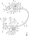
- FIG 1 is a schematic of an oral irrigator 100.
- the oral irrigator comprises a high pressure water delivery system 101 and a low pressure mouth rinse delivery system 103. Both systems are housed in part in a console 102 and an attached handle 104. Attachment is by a flexible supply tube 109.
- the water delivery system comprises a water supply tube 122. This conveys high pressure water from a source of high pressure water 136, such as the piping leading into a shower head 138.
- a three way valve 142 may be provided to redirect high pressure water from the shower head to the water delivery system.
- Any source of high pressure water may be used, such as an electrically driven pump.
- the water should have a minimum pressure of 0.695 bar. 2.75 to 4.13 bar is suitable.
- An electrically driven pump may be provided to boost and control the pressure of the water from the high pressure source.
- the electrically driven pump may be battery operated.
- a pressure regulator may be provided to reduce and control the pressure from the high pressure source of water.
- a pressure regulator may be needed if the source of high pressure water is 6.89 bar or more.
- a filter 123 such as a screen, may be provided in the water supply tube to remove particulates from the supply water.
- the water supply tube proceeds into and through the console.
- the console may be mounted on the wall of a shower. Any mounting means may be used.
- the console may be mounted in any convenient location such as next to a sink.
- a shut off valve 118 may be provided in the water supply tube and as part of the console. A user can turn the high pressure water on or off using the shut off valve. The user can also regulate the flow of high pressure water to an intermediate value by partially closing the shut off valve.
- the water supply tube may be connected to a console bulkhead fitting 146 at about the bottom of the console.
- the attachment of tubes to bulkhead fittings may be permanent or removable (e.g. insert fittings).
- the flexible supply tube may connect to the console bulkhead fitting and convey both high pressure water and low pressure mouth rinse to the handle as separate streams.
- the flexible supply tube may be a dual lumen tube.
- the first lumen 110 of said dual lumen tube may have a relatively large internal diameter and connect to the water supply tube via said console bulkhead fitting.
- a relatively large diameter minimizes the pressure drop of the high pressure water as it passes through the first lumen.
- a suitable internal diameter is 3 mm or greater.
- a suitable diameter may further be in the range of 4.5 to 7.5 mm.
- the flexible supply tube can be any length suitable for conveying high pressure water from the console to the handle.
- a suitable length is in the range of .5 to 2 meters.
- a suitable length is about 1 meter.
- the console may comprise a reservoir 114 for holding a volume of mouth rinse 128.
- Mouth rinse may be any fluid suitable for introduction into a person's mouth.
- the reservoir may have an open top 130 and thus be at about atmospheric pressure (i.e. 0.0 bar).
- a mouth rinse tube 144 may proceed from inside the reservoir at about its bottom, over about the top of the reservoir, and then outside of the reservoir and down to the console bulkhead fitting.
- the mouth rinse tube may then be connected to the second lumen 108 of the flexible supply tube.
- the internal diameter of the second lumen may be small relative to the internal diameter of the first lumen. This keeps the volume of the second lumen small so that a user does not have to pump a hand pump 156 in the handle many times in order to deliver mouth rinse to a pick 106.
- a suitable diameter for the second lumen is 4 mm or less.
- a suitable diameter may be in the range of 2.75 mm to 3.25 mm.
- the lumens in the flexible supply tube do not have to be circular in cross section. They can be any suitable shape. Suitable dimensions for the noncircular lumens can be calculated from the corresponding suitable diameters of the circular lumens described herein using standard fluid mechanical calculations related to volume in a tube and/or pressure drop versus flow.
- the console may comprise a console mount 115. This will be mated to a handle mount 162 on the handle. The combined mounts will hold the handle in a storage position when not in use.
- the console mount may comprise a magnet 132 and a shelf 134.
- the handle mount may comprise a magnet 164 and an overhang 166. The magnets, shelf and overhang align so that the overhang sits on the shelf and the magnets are about opposite of each other and urge towards each other when the handle is mounted on the console.
- the shelf height is set so that the exit orifice 120 of the pick is above the top of the reservoir 130. This will prevent mouth rinse from siphoning through the mouth rinse delivery system when the handle is stored on the console.
- the console may have a housing 112.
- a cover 124 may be provided in the console housing and above the top of the reservoir to prevent shower water or other materials from entering the reservoir.
- the cover may be hinged to allow easy opening and refilling of the reservoir.
- a level gauge 105 may be provided so that the user can see when the reservoir needs to be refilled.
- a storage chamber 116 may be provided in the console.
- the storage chamber may be used to store one or more additional picks 140.
- the additional picks may be used by different people that use the oral irrigator.
- the picks may be color coded.
- a door 126 may be provided in the console housing to cover the storage chamber.
- the flexible supply tube conveys high pressure water and low pressure mouth rinse to the handle 104.
- the flexible supply tube may connect to a bottom bulkhead fitting 182 in the bottom of the handle.
- the first lumen of the flexible supply tube connects to an inlet water tube 184 in the handle.
- the inlet water tube connects to the inlet of a blocking valve 154 mounted in the handle.
- the outlet of the blocking valve connects to an outlet water tube 160.
- the outlet water tube may connect to the inlet of an optional pressure oscillator 158.
- the outlet of the pressure oscillator 190 connects to a top bulkhead fitting 186 in about the top of the handle.
- the pick 106 connects to the top bulkhead fitting.
- a releasable connection may be provided in the top bulkhead fitting to hold the pick in place and then release it as needed.
- the releasable connection may be a quick disconnect that can be operated by hand.
- the blocking valve comprises a body 168 and a spring loaded valve button 170.
- the handle may comprise a housing 152.
- the body of the blocking valve may rest against the housing of the handle so that it is held firmly in place when pressure is placed on the spring loaded valve button.
- the spring loaded valve button is biased normally open. When the button is pressed, the blocking valve closes. When the button is released, the blocking valve opens.
- the second lumen in the flexible supply tube is connected through the bottom bulkhead fitting of the handle to a flexible inlet mouth rinse tube 192.
- the inlet mouth rinse tube connects to an inlet check valve 178 of the hand pump 156.
- the hand pump comprises the inlet check valve, a spring loaded piston 174, a pump button 176 and an outlet check valve 172.
- the outlet check valve connects to a flexible outlet mouth rinse tube 194.
- the outlet mouth rinse tube connects to the oscillator outlet 190.
- the hand pump may be flexibly mounted inside the handle housing and adjacent to the blocking valve so that when the pump button is pressed and lateral force is placed on the spring loaded piston, the spring loaded piston can move laterally and provide force on the valve button and thus close the blocking valve.
- the blocking valve is closed, the high pressure water in the pick drains out and the pressure in the oscillator outlet drops.
- the spring loaded piston can then compress under the hand force placed on the pump button and mouth rinse is pumped into the oscillator outlet and hence into the pick.
- the valve button on the blocking valve returns to its open position and high pressure water flows back into the pick.
- the blocking valve and the hand pump may be mounted side by side in the handle.
- the valve button and pump button may then be mechanically connected such that when the user pushes the pump button down, the valve button is pushed down and closes the blocking valve before the spring loaded piston is compressed by the pump button.
- the hand pump and blocking valve may be rigidly mounted inside the handle housing and adjacent to each other when the hand pump and blocking valve are in a side by side configuration.
- the outlet check valve in the hand pump is biased away from the spring loaded piston so that said outlet check valve prevents high pressure water downstream of the blocking valve from backflowing into the hand pump.
- the inlet check valve on the hand pump is biased into the spring loaded piston so that mouth rinse does not backflow into the reservoir when said spring loaded piston is compressed.
- the pressure oscillator 158 may be any device that causes fluctuations in the pressure of the water flowing into the pick. This includes mechanical devices, electrically powered devices, and fluidic devices. An exemplary turbine based pressure oscillator is described herein with reference to figures 6 and 7 . A pressure oscillator is not required, however. The system is still efficacious if there is no pressure oscillator.
- FIG. 2 is a rendering of an exemplary handle 200.
- the handle comprises a top bulkhead fitting 204, a housing 202, and a bottom bulkhead fitting 206.
- the housing is shaped to provide an overhang 224 above a bulge 222. This provides a grip for a user that will be secure even if the user has a slippery hand due to, for example, use in a shower.
- the overhang forms part of a handle mount.
- a magnet 226 may be provided inside the housing and underneath the overhang to mate with a corresponding magnet in a console. Any shape housing may be used, however, provided it can be held in a person's hand.
- a pick button 212 may be provided so that a pick 214, may be held in place in the top bulkhead fitting. When the pick button is depressed, the pick is released. Any means of holding the pick, however, may be used.
- a pump button 208 may protrude out of the housing so that a user may depress the pump button and pump mouth rinse into the pick as described above.
- the bottom bulkhead fitting may be adapted to receive an end of a dual lumen flexible supply tube 232.
- the flexible supply tube may comprise a first lumen 234 for conveying high pressure water and a second lumen 236 for conveying low pressure mouth rinse.
- the tubing does not have to be dual lumen. Separate tubes for the mouth rinse and high pressure water may be used.
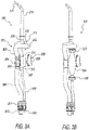
- Figure 3A is a rendering 300 of the handle of figure 2 with the housing removed so that the internal fluid systems can be seen.
- the internal fluid systems comprise portions of the water delivery system 301 and mouth rinse delivery system 303.
- the water delivery system in the handle comprises a first lumen 342 in the bottom bulkhead fitting 307 (cover removed), a water inlet tube 308, a blocking valve 304 comprising a valve button 306, a water outlet tube 302 and a pressure oscillator 314.
- the pressure oscillator is hidden by the water outlet tube in the view presented in Figure 3A . It is visible as item 314 in figure 5 .
- the pick 214 is shown mounted in the outlet of the pressure oscillator with the top bulkhead fitting that holds the pick in place rendered invisible.
- a pick exit orifice 324 is shown at the distal tip of the pick.
- a pick inlet 326 is shown at the proximal end of the pick.
- the mouth rinse delivery system in the handle comprises a second lumen 344 in the bottom bulkhead fitting, an inlet mouth rinse tube 322, a hand pump 305 and an outlet mouth rinse tube 312.
- the hand pump comprises an inlet check valve 320, a spring loaded piston 318, the pump button 208, and an outlet check valve 316.
- the hand pump may be flexibly mounted inside the handle with its bottom located on the top of the valve button of the blocking valve. The blocking valve rests against the handle housing (item 202, figure 2 ) so that the blocking valve will be firmly mounted in place and the valve button can be depressed when the pump button on the hand pump is pressed and the bottom of the spring loaded piston is pushed down.
- Figure 3B is a rendering of a handle 331 similar to the handle 300 of figure 3A except the spring loaded piston is shown as an elastomeric bladder 334.
- the outlet check valve 332 and inlet check valve 336 are shown as flap valves. Any configuration of spring loaded piston may be used provided said spring loaded piston can be mounted in a handle held by a person.
- Figure 4 is a cut away side view of the blocking valve 304 of figure 3A in combination with the hand pump 305 of Figure 3A .
- the pick 214, pressure oscillator 314, outlet water tube 302, and inlet water tube 308 are shown schematically.
- the blocking valve comprises a body 402, a cap 404, and a spring loaded valve button 306.
- the body comprises an inlet 412, an internal channel 416, a lateral bore 424 at right angles to the internal channel, and an outlet 414.
- the spring loaded valve button comprises a shaft 406, a spring 426 and a distal tip 422.
- the inlet and outlet of the blocking valve are collinear so that pressurized water can flow from the bottom of the handle up to the pick mounted in the top of the handle.
- the collinearity of the inlet and outlet helps keep the width 410 of the blocking valve to less than twice the diameter of the inlet water tube or outlet water tube. This helps keep the overall width of the handle small enough to fit in a person's hand.
- a suitable width of the blocking valve is 12.5 mm.
- a suitable outer diameter of the inlet water tube is 8.5 mm.
- a suitable ratio of the width of the blocking valve to the outer diameter of the inlet water tube is 1.5 or less.
- the inlet and outlet of the blocking valve may be codirectional with a lateral offset therebetween.
- codirectional means that the longitudinal axis of the inlet and the longitudinal axis of the outlet are in about the same direction, but the axes may be offset laterally from each other. Collinearity is a special case of unidirectionality where the lateral offset is about zero. An offset that is greater than about zero may be referred to as a "dog leg".
- the valve button is mounted horizontally in the bore of the valve body.
- the spring 426 surrounds the shaft of the valve button. The spring is normally compressed so that it biases the valve button out.
- a seal 428 such as an O ring, may be provided to make the spring loaded valve button water tight against the bore.
- the cap 404 may screw onto, snap onto, press fit onto or otherwise attached to the valve body to hold the valve button in the bore.
- the tip of the valve button may partially extend into the internal channel of the valve body. 1 mm is a suitable extension for a diameter of the internal channel of 2 mm. A recessed seat 418 may be provided in the internal channel and opposite the tip of the valve button. When the valve button is pressed in, the tip proceeds across the rest of the internal channel and into the seat to seal off said internal channel.
- the outer diameter of the shaft should be larger than the internal diameter of the internal channel so that it completely blocks the internal channel when the blocking valve is closed.
- a suitable outer diameter of the shaft is 3 mm when the internal diameter of the internal channel is 2 mm.
- the diameter of the internal channel has to be small so that the tip of the valve button does not have to travel far to close the blocking valve. This helps keep the length of the valve button that extends above the top of the cap small.
- a suitable diameter of the internal channel is 2 mm.
- a suitable internal diameter of the inlet and outlet of the blocking valve is about 4.5 mm. It is surprising that the diameter of the internal channel can be less than 1 ⁇ 2 of the diameter of the inlet or outlet. Normally this would produce an unacceptable pressure drop in a general purpose blocking valve. In the applications described herein, however, small diameter of the internal channel is acceptable due in part to the even smaller diameter of the exit orifice 324 in the pick.
- a suitable diameter of the exit orifice is in the range of 0.45 to 1.0 mm. This is required to get maximum velocity in the high pressure water exiting the pick without causing atomization. Thus most of the pressure drop of the high pressure water flowing through the handle occurs at the exit orifice of the pick where it translates to a high velocity water jet for cleaning teeth.
- the hand pump 305 in figure 4 comprises an outlet check valve 316 (shown schematically), a cylinder 436, a spring loaded piston 318 and an inlet check valve 320 (shown schematically).
- the piston is mounted within the cylinder.
- a piston shaft 444 and piston spring 442 extend laterally from the piston and are mounted to the pump button 208.
- a recess 432 is provided in the bottom of the cylinder.
- the valve button of the blocking valve is located in the recess. The recess may be large enough to fit over the top of the cap of the blocking valve.
- a leading edge of mouth rinse 438 is shown emerging from the outlet check valve when the pump button is pressed, the blocking valve is closed, and mouth rinse is pumped to the pick.
- the outlet of the hand pump is connected to the outlet of the pressure oscillator and hence to the inlet of the pick.
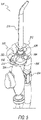
- FIG. 5 is a rendering of the handle 331 of figure 3B with the pressure oscillator 314 visible.
- the blocking valve 304 and elastomeric bladder 334 are also shown.
- the pressure oscillator comprises an oscillator inlet 502, an oscillator outlet 504, a turbine housing 506, one or more mounting tabs 512 and a mouth rinse port 508.
- the outlet water tube 302 proceeds from the blocking valve and is bent to introduce high pressure water horizontally into the turbine housing.
- the oscillator outlet proceeds upwards from the top of the turbine housing where it connects to the pick 214.
- the outlet mouth rinse tube 312 proceeds up from the elastomeric bladder and connects horizontally to the mouth rinse port.
- the mouth rinse port is connected to the oscillator outlet.
- only water proceeds through the pressure oscillator. This minimizes clogging that might occur due to chemicals or other materials that may be present in the mouth rinse. It also reduces the hand pressure required to pump mouth rinse into the pick.
- Figure 6 is a rendering of the pressure oscillator 314 of figure 5 .
- the oscillator inlet 502, oscillator outlet 504, turbine housing 506 mouth rinse port 508 and mounting tabs 512 can be seen.
- the turbine housing comprises a top 602, side wall 604 and bottom 606.
- FIG. 7 is a cut away bottom view of the pressure oscillator 314 of figure 5 .
- the oscillator inlet 502, oscillator outlet 504, and mouth rinse port 508 can be seen.
- the pressure oscillator comprises a turbine 700.
- the turbine comprises a turbine housing 506 and a turbine wheel 702.
- the turbine housing comprises a top 602, a side wall 604 and a bottom (item 606, figure 6 ).
- the turbine wheel comprises a hub 714, and a plurality of vanes 712.
- the turbine side wall has a generally circular horizontal cross section.
- a turbine inlet 708 introduces high pressure water into the housing from the oscillator inlet in a direction that is generally tangential to the side wall.
- a turbine outlet 704 is located in the turbine top.
- the turbine outlet allows water to flow from the turbine into the outlet of the pressure oscillator.
- the mouth rinse port 508 is downstream of the turbine outlet.
- the turbine housing comprises a vertical axle 706 located at about the center of the circular cross section of the side wall.
- the vertical axle can be attached to either the top of the turbine housing or the bottom.
- the hub of the turbine wheel sits on the axle.
- the turbine vanes proceed radially from the hub. They are spaced regularly on the hub.
- Each vane has a distal tip 732.
- Each vane is described by a width 710 and a length 711.
- a suitable width of the vanes is 1 mm or greater for a turbine outlet diameter of about 3 mm.
- the diameter of the side wall is about 13 mm. It has been found by experiment that a relatively wide gap of .5 mm or greater between the tips of the vanes and the side wall helps the turbine wheel spin freely. A suitable ratio of gap to side wall diameter, therefore, is 0.03 or greater.
- a suitable hub diameter is about 5.5 mm.
- a suitable overall wheel diameter is about 12 mm. 6 is a suitable number of vanes.
- the turbine outlet should be located far enough away from the turbine inlet so that there is always at least one vane between the inlet and outlet. This will prevent water from flowing directly to the outlet without rotating the vanes.
- the closest spacing 718 between the turbine inlet and outlet therefore, should be greater than the spacing 716 between the tips of two adjacent vanes. If the vane tips are spaced 5.5 mm apart, for example, then the closest spacing between the turbine inlet and the turbine outlet should be at least 5.5 mm. A spacing of 5.9 mm is suitable.
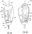
- FIG 8A is a rendering of an exemplary console 800.
- the console comprises a housing 810, a reservoir for mouth rinse (item 902, figure 9A ), a reservoir cover 802, a reservoir level gauge 812, a water supply tube 816, a shelf 808, a shut off valve 814, a console bulkhead fitting 818, a left storage door 804 and a right storage door 806.
- the dual lumen flexible supply tube 232 of figure 2 is attached to the bottom of the console bulkhead fitting.
- the console bulkhead fitting is attached to about the bottom of the console.
- the water supply tube conveys high pressure water from a source of high pressure water to the console bulkhead fitting.
- the shut off valve is adapted to close the water supply tube or open it as required.
- the reservoir cover is attached to the top of the housing with a rear hinge. It overhangs the housing to form an air passage 822 from outside the housing to underneath the cover. This allows air to go into the reservoir when mouth rinse is pumped out.
- the left side door and right side door are each attached to the back of the housing by a hinge.
- the shelf 808 is designed to form a stable cradle for the overhang 224 ( Figure 2 ) of the handle.
- a "stable cradle” is a mount that holds an item such that said item is held on said mount by the force of gravity.
- Said shelf forms a stable cradle for said overhang in part due to said self's arcuate form which wraps in part around the handle underneath the overhang.
- a magnet may still be provided, for example, in the shut off valve 814 so that the magnet in the handle will urge towards it and increase the stability of the handle being held on the cradle.
- Figure 8B is a rendering 830 of the console of figure 8A with the reservoir cover and right storage door removed.
- a reservoir inlet 832 can be seen.
- a user can open the reservoir cover and pour mouth rinse into the reservoir inlet. The cover can then be closed to keep foreign matter, including shower water, from entering the reservoir.
- the right storage chamber 834 has room for one or more extra picks 836.
- the picks may be held in place by one or more clips 838.
- the picks may be color coded 842 so that different colored picks can be assigned to different users.
- the storage chamber is wider at its top than at its bottom.
- the top area may have clips or other holders for storing wider picks, such as the massager pick described in figure 11 .
- a similar or different structure may be provided in a left storage chamber that is covered by the left storage door.
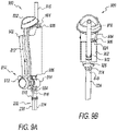
- Figure 9A is a rendering 900 of the console of figure 8A and 8B with the housing removed.
- the water supply tube 816, reservoir inlet 832, level gauge 812, shut off valve 814 and console bulkhead fitting 818 (cover removed) are visible.
- the reservoir 902 can now be seen.
- the reservoir can be made of any material compatible with mouth rinses. Polyethylene is a suitable material. The material may be at least translucent or transparent so that the level of mouth rinse can be seen in the level gauge.
- the shape of the reservoir can be adapted to conform to the desired housing shape.
- the reservoir comprises a top 908 and a bottom 906.
- a console mouth rinse tube 904 may proceed from about the bottom of the reservoir to the top of the reservoir and then back down to the console bulkhead fitting. There it is connected to the second lumen 236 of the flexible supply tube 232.
- the shut off valve comprises a handle 912 and a body 914.
- the water supply tube connects to the body of the shut off valve and is shut off when the handle is turned.
- the shut off valve may be a ball valve.
- the shut off valve may alternatively be a regulating valve in case the pressure delivered to the handle needs to be reduced.
- Figure 9B is a rendering 900 of the console of figure 9A from a top rear perspective.
- the water supply tube 816 proceeds down through a U channel 922 in the reservoir 902. It then connects to the body of the shut off valve 914. A connection is then made to the console bulkhead fitting and first lumen 234 of the flexible supply tube.
- a shelf 926 may be provided to support the reservoir.
- the console mouth rinse tube 904 can be seen emerging from the top of the reservoir 908.
- a clip 924 is provided to secure the console mouth rinse tube.
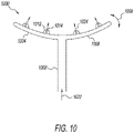
- FIG 10 is a drawing of a massager pick 1000, not according to the invention.
- the massager pick may be used to massage a person's gums and/or clean said person's teeth.
- the massager pick comprises an inlet tube 1002 where fluid goes in 1022, a left side branch 1004 and a right side branch 1006.
- the left side branch and right side branch proceed horizontally from the distal end of the inlet tube.
- Said branches may be curved.
- Said branches may be flexible 1008.
- a plurality of exit orifices 1014 may be on said branches. Said exit orifices may all be on the same side of the branches.
- the outlet water 1024 will impinge the same side of said person's teeth and gums.
- Raised nubs 1012 may be provided on the left and right side branches.
- the orifices may proceed through said nubs.
- the nubs may be rubbed against a person's gums for a massaging effect.
- only one branch may be provided in the massager pick.
- FIG 11 is a longitudinal cross sectional rendering of an massager pick 1100 according to an embodiment of the invention.
- the massager pick comprises an inlet tube 1102, a hollow left side branch 1104, a hollow right side branch 1106 and a hollow bridge 1113.
- the inlet tube has an inlet 1152 and an outlet 1154.
- the left side branch has an inlet 1166 and an outlet 1168.
- the right side branch has an inlet 1156 and an outlet 1158.
- the bridge has a left end 1164, a right end 1162 and a top surface 1108.
- the outlet of the inlet tube is connected to the inlets of the left and right side branches.
- the outlets of the left and right side branches are connected to the left and right ends of the bridge.
- the bridge may have a longitudinal concave arcuate shape 1172.
- the inlet tube, left side branch, right side branch and bridge may be made from a rigid material 1117 such as plastic.
- the bridge may nonetheless be flexible enough so that it bends in or out when pressed against a surface with a smaller or larger radius of curvature than the radius of curvature of the concave arcuate shape.
- the arcuate shape of the bridge may conform to the shape of a user's teeth or gums when the massager pick is pressed against them using the normal force a person could provide. It may then return to its original shape when removed from said person's mouth.
- the massager may be designed to conform to a person's mouth shape upon initial use and remain in said shape when removed from said person's mouth.
- the top surface of the bridge comprises a plurality of upward directed converging nozzles 1116.
- the upward wall of the bridge is covered with a layer of elastomer 1115 that is shaped into a plurality of upward directed nubs 1112.
- Each exit orifice passes through one of the upward directed nozzles and upward directed nubs.
- the portions of the exit orifices that passes through the layer of elastomer may flare out. This may create a subatmospheric pressure at the interface of the bridge and the elastomeric layer. The subatmospheric pressure will reduce the likelihood of the water inside the exit orifice from leaking between the elastomeric layer and the top surface of the bridge and thus causing the two to separate from each other.
- the elastomeric layer may also be stepped back from the exit orifices in the bridge. This will reduce the possibility of stray flashing from a molding process used to make the elastomeric layer from overlapping the exit orifices and directing water underneath the elastomeric layer.
- the inlet tube 1102 may comprise an inlet fitting 1103.
- the inlet fitting may be adapted to reversibly connect to an adapter fitting 1122.
- a thread 1105 and O ring 1107 may be provided to connect the inlet fitting to the adapter fitting.
- the adapter fitting may comprise one of a number of alternative connection means, such as a quick disconnect 1124.
- Figure 11 shows an alternative adapter fitting 1132 that comprises a tubing fitting 1134.
- inlet fitting itself may be a quick disconnect, tubing or other appropriate fitting.
Landscapes
- Health & Medical Sciences (AREA)
- Life Sciences & Earth Sciences (AREA)
- Animal Behavior & Ethology (AREA)
- General Health & Medical Sciences (AREA)
- Public Health (AREA)
- Veterinary Medicine (AREA)
- Epidemiology (AREA)
- Engineering & Computer Science (AREA)
- Dentistry (AREA)
- Heart & Thoracic Surgery (AREA)
- Biomedical Technology (AREA)
- Anesthesiology (AREA)
- Hematology (AREA)
- Water Supply & Treatment (AREA)
- Pain & Pain Management (AREA)
- Physical Education & Sports Medicine (AREA)
- Rehabilitation Therapy (AREA)
- Oral & Maxillofacial Surgery (AREA)
- Massaging Devices (AREA)
- Nozzles (AREA)
- Pulmonology (AREA)
- Domestic Plumbing Installations (AREA)
Description
- Embodiments of the present invention relate to teeth and gum cleaning devices.
- Current designs for oral irrigators combine mouth rinses with water in a common reservoir and use an electrically driven pump to deliver the mixture at high pressure to a pick. The high pressure flow may be a pulsatile flow. A user places the pick in said user's mouth to clean said user's teeth and irrigate said user's gums.
- Picks for oral irrigators are known from
US 6 689 078 B1 andJP 2006 141913 A - The invention pertains to a massager pick for an oral irrigator, as specified in claim 1. Optional features of the massager pick are presented in dependent claims 2 and 3.
-
-
Figure 1 is a schematic of an oral irrigator (not claimed), in which the massager pick according to the invention may be used. -
Figure 2 is a rendering of an exemplary handle. -
Figure 3A is a rendering of the handle offigure 2 with the housing removed so the internal fluid systems can be seen. -
Figure 3B is a rendering of a handle similar to the handle offigure 3A except the spring loaded piston is shown as an elastomeric bladder. -
Figure 4 is a cut away side view of the blocking valve offigure 3A in combination with the hand pump ofFigure 3A . -
Figure 5 is a rendering of the handle offigure 3B from a top perspective so that a pressure oscillator in the handle is visible. -
Figure 6 is a rendering of the pressure oscillator offigure 5 . -
Figure 7 is a cut away bottom view of the pressure oscillator offigure 5 showing an internal turbine wheel. -
Figure 8A is a rendering of a console. -
Figure 8B is a rendering of the console offigure 8A with the reservoir cover and right storage door removed. -
Figure 9A is a rendering of the console offigure 8A with the housing removed to show the mouth rinse reservoir inside. -
Figure 9B is a rendering of the console offigure 9A from a top rear perspective. -
Figure 10 is a drawing of an example of a massager pick with left and right side branches and multiple exit orifices, not according to the invention. -
Figure 11 is a longitudinal cross sectional rendering of an exemplary massager pick according to an embodiment of the invention. - The detailed description describes non-limiting exemplary embodiments. Any individual features may be combined with other features as required by different applications for at least the benefits described herein.
- As used herein, the term "about" means plus or minus 10% of a given value unless specifically indicated otherwise.
- As used herein, the term "shaped" means that an item has the overall appearance of a given shape even if there are minor variations from the pure form of said given shape.
- As used herein, the term "substantially" means more than 90% of a given value unless specifically indicated otherwise.
-
Figure 1 is a schematic of anoral irrigator 100. The oral irrigator comprises a high pressurewater delivery system 101 and a low pressure mouthrinse delivery system 103. Both systems are housed in part in aconsole 102 and an attachedhandle 104. Attachment is by aflexible supply tube 109. - The water delivery system comprises a
water supply tube 122. This conveys high pressure water from a source ofhigh pressure water 136, such as the piping leading into ashower head 138. A threeway valve 142 may be provided to redirect high pressure water from the shower head to the water delivery system. Any source of high pressure water may be used, such as an electrically driven pump. The water should have a minimum pressure of 0.695 bar. 2.75 to 4.13 bar is suitable. An electrically driven pump may be provided to boost and control the pressure of the water from the high pressure source. The electrically driven pump may be battery operated. A pressure regulator may be provided to reduce and control the pressure from the high pressure source of water. A pressure regulator may be needed if the source of high pressure water is 6.89 bar or more. A filter 123, such as a screen, may be provided in the water supply tube to remove particulates from the supply water. - The water supply tube proceeds into and through the console. The console may be mounted on the wall of a shower. Any mounting means may be used. The console may be mounted in any convenient location such as next to a sink. A shut off
valve 118 may be provided in the water supply tube and as part of the console. A user can turn the high pressure water on or off using the shut off valve. The user can also regulate the flow of high pressure water to an intermediate value by partially closing the shut off valve. The water supply tube may be connected to a console bulkhead fitting 146 at about the bottom of the console. The attachment of tubes to bulkhead fittings may be permanent or removable (e.g. insert fittings). The flexible supply tube may connect to the console bulkhead fitting and convey both high pressure water and low pressure mouth rinse to the handle as separate streams. The flexible supply tube may be a dual lumen tube. Thefirst lumen 110 of said dual lumen tube may have a relatively large internal diameter and connect to the water supply tube via said console bulkhead fitting. A relatively large diameter minimizes the pressure drop of the high pressure water as it passes through the first lumen. A suitable internal diameter is 3 mm or greater. A suitable diameter may further be in the range of 4.5 to 7.5 mm. The flexible supply tube can be any length suitable for conveying high pressure water from the console to the handle. A suitable length is in the range of .5 to 2 meters. A suitable length is about 1 meter. - The console may comprise a
reservoir 114 for holding a volume of mouth rinse 128. Mouth rinse may be any fluid suitable for introduction into a person's mouth. The reservoir may have anopen top 130 and thus be at about atmospheric pressure (i.e. 0.0 bar). A mouth rinsetube 144 may proceed from inside the reservoir at about its bottom, over about the top of the reservoir, and then outside of the reservoir and down to the console bulkhead fitting. The mouth rinse tube may then be connected to thesecond lumen 108 of the flexible supply tube. The internal diameter of the second lumen may be small relative to the internal diameter of the first lumen. This keeps the volume of the second lumen small so that a user does not have to pump ahand pump 156 in the handle many times in order to deliver mouth rinse to apick 106. A suitable diameter for the second lumen is 4 mm or less. A suitable diameter may be in the range of 2.75 mm to 3.25 mm. - The lumens in the flexible supply tube do not have to be circular in cross section. They can be any suitable shape. Suitable dimensions for the noncircular lumens can be calculated from the corresponding suitable diameters of the circular lumens described herein using standard fluid mechanical calculations related to volume in a tube and/or pressure drop versus flow.
- The console may comprise a
console mount 115. This will be mated to ahandle mount 162 on the handle. The combined mounts will hold the handle in a storage position when not in use. The console mount may comprise amagnet 132 and ashelf 134. The handle mount may comprise amagnet 164 and anoverhang 166. The magnets, shelf and overhang align so that the overhang sits on the shelf and the magnets are about opposite of each other and urge towards each other when the handle is mounted on the console. The shelf height is set so that theexit orifice 120 of the pick is above the top of thereservoir 130. This will prevent mouth rinse from siphoning through the mouth rinse delivery system when the handle is stored on the console. - The console may have a
housing 112. Acover 124 may be provided in the console housing and above the top of the reservoir to prevent shower water or other materials from entering the reservoir. The cover may be hinged to allow easy opening and refilling of the reservoir. Alevel gauge 105 may be provided so that the user can see when the reservoir needs to be refilled. - A
storage chamber 116 may be provided in the console. The storage chamber may be used to store one or moreadditional picks 140. The additional picks may be used by different people that use the oral irrigator. The picks may be color coded. Adoor 126 may be provided in the console housing to cover the storage chamber. - The flexible supply tube conveys high pressure water and low pressure mouth rinse to the
handle 104. The flexible supply tube may connect to a bottom bulkhead fitting 182 in the bottom of the handle. The first lumen of the flexible supply tube connects to aninlet water tube 184 in the handle. The inlet water tube connects to the inlet of a blockingvalve 154 mounted in the handle. The outlet of the blocking valve connects to anoutlet water tube 160. The outlet water tube may connect to the inlet of anoptional pressure oscillator 158. The outlet of thepressure oscillator 190 connects to a top bulkhead fitting 186 in about the top of the handle. Thepick 106 connects to the top bulkhead fitting. A releasable connection may be provided in the top bulkhead fitting to hold the pick in place and then release it as needed. The releasable connection may be a quick disconnect that can be operated by hand. - The blocking valve comprises a
body 168 and a spring loadedvalve button 170. The handle may comprise ahousing 152. The body of the blocking valve may rest against the housing of the handle so that it is held firmly in place when pressure is placed on the spring loaded valve button. The spring loaded valve button is biased normally open. When the button is pressed, the blocking valve closes. When the button is released, the blocking valve opens. - The second lumen in the flexible supply tube is connected through the bottom bulkhead fitting of the handle to a flexible inlet mouth rinse
tube 192. The inlet mouth rinse tube connects to aninlet check valve 178 of thehand pump 156. The hand pump comprises the inlet check valve, a spring loadedpiston 174, apump button 176 and an outlet check valve 172. The outlet check valve connects to a flexible outlet mouth rinsetube 194. The outlet mouth rinse tube connects to theoscillator outlet 190. - The hand pump may be flexibly mounted inside the handle housing and adjacent to the blocking valve so that when the pump button is pressed and lateral force is placed on the spring loaded piston, the spring loaded piston can move laterally and provide force on the valve button and thus close the blocking valve. When the blocking valve is closed, the high pressure water in the pick drains out and the pressure in the oscillator outlet drops. The spring loaded piston can then compress under the hand force placed on the pump button and mouth rinse is pumped into the oscillator outlet and hence into the pick. When the pump button is released, the valve button on the blocking valve returns to its open position and high pressure water flows back into the pick.
- Alternatively, the blocking valve and the hand pump may be mounted side by side in the handle. The valve button and pump button may then be mechanically connected such that when the user pushes the pump button down, the valve button is pushed down and closes the blocking valve before the spring loaded piston is compressed by the pump button. The hand pump and blocking valve may be rigidly mounted inside the handle housing and adjacent to each other when the hand pump and blocking valve are in a side by side configuration.
- The outlet check valve in the hand pump is biased away from the spring loaded piston so that said outlet check valve prevents high pressure water downstream of the blocking valve from backflowing into the hand pump. The inlet check valve on the hand pump is biased into the spring loaded piston so that mouth rinse does not backflow into the reservoir when said spring loaded piston is compressed.
- The
pressure oscillator 158 may be any device that causes fluctuations in the pressure of the water flowing into the pick. This includes mechanical devices, electrically powered devices, and fluidic devices. An exemplary turbine based pressure oscillator is described herein with reference tofigures 6 and7 . A pressure oscillator is not required, however. The system is still efficacious if there is no pressure oscillator. -
Figure 2 is a rendering of anexemplary handle 200. The handle comprises a top bulkhead fitting 204, ahousing 202, and a bottom bulkhead fitting 206. The housing is shaped to provide anoverhang 224 above abulge 222. This provides a grip for a user that will be secure even if the user has a slippery hand due to, for example, use in a shower. The overhang forms part of a handle mount. Amagnet 226 may be provided inside the housing and underneath the overhang to mate with a corresponding magnet in a console. Any shape housing may be used, however, provided it can be held in a person's hand. - A
pick button 212 may be provided so that apick 214, may be held in place in the top bulkhead fitting. When the pick button is depressed, the pick is released. Any means of holding the pick, however, may be used. - A
pump button 208 may protrude out of the housing so that a user may depress the pump button and pump mouth rinse into the pick as described above. - The bottom bulkhead fitting may be adapted to receive an end of a dual lumen
flexible supply tube 232. The flexible supply tube may comprise afirst lumen 234 for conveying high pressure water and asecond lumen 236 for conveying low pressure mouth rinse. The tubing does not have to be dual lumen. Separate tubes for the mouth rinse and high pressure water may be used. -
Figure 3A is arendering 300 of the handle offigure 2 with the housing removed so that the internal fluid systems can be seen. The internal fluid systems comprise portions of thewater delivery system 301 and mouth rinsedelivery system 303. The water delivery system in the handle comprises afirst lumen 342 in the bottom bulkhead fitting 307 (cover removed), awater inlet tube 308, a blockingvalve 304 comprising avalve button 306, awater outlet tube 302 and apressure oscillator 314. The pressure oscillator is hidden by the water outlet tube in the view presented inFigure 3A . It is visible asitem 314 infigure 5 . Thepick 214 is shown mounted in the outlet of the pressure oscillator with the top bulkhead fitting that holds the pick in place rendered invisible. Apick exit orifice 324 is shown at the distal tip of the pick. Apick inlet 326 is shown at the proximal end of the pick. - The mouth rinse delivery system in the handle comprises a
second lumen 344 in the bottom bulkhead fitting, an inlet mouth rinsetube 322, ahand pump 305 and an outlet mouth rinsetube 312. The hand pump comprises aninlet check valve 320, a spring loadedpiston 318, thepump button 208, and anoutlet check valve 316. The hand pump may be flexibly mounted inside the handle with its bottom located on the top of the valve button of the blocking valve. The blocking valve rests against the handle housing (item 202,figure 2 ) so that the blocking valve will be firmly mounted in place and the valve button can be depressed when the pump button on the hand pump is pressed and the bottom of the spring loaded piston is pushed down. -
Figure 3B is a rendering of ahandle 331 similar to thehandle 300 offigure 3A except the spring loaded piston is shown as anelastomeric bladder 334. Theoutlet check valve 332 andinlet check valve 336 are shown as flap valves. Any configuration of spring loaded piston may be used provided said spring loaded piston can be mounted in a handle held by a person. -
Figure 4 is a cut away side view of the blockingvalve 304 offigure 3A in combination with thehand pump 305 ofFigure 3A . Thepick 214,pressure oscillator 314,outlet water tube 302, andinlet water tube 308 are shown schematically. - The blocking valve comprises a
body 402, acap 404, and a spring loadedvalve button 306. The body comprises aninlet 412, aninternal channel 416, alateral bore 424 at right angles to the internal channel, and anoutlet 414. The spring loaded valve button comprises ashaft 406, aspring 426 and adistal tip 422. - The inlet and outlet of the blocking valve are collinear so that pressurized water can flow from the bottom of the handle up to the pick mounted in the top of the handle. The collinearity of the inlet and outlet helps keep the
width 410 of the blocking valve to less than twice the diameter of the inlet water tube or outlet water tube. This helps keep the overall width of the handle small enough to fit in a person's hand. A suitable width of the blocking valve is 12.5 mm. A suitable outer diameter of the inlet water tube is 8.5 mm. A suitable ratio of the width of the blocking valve to the outer diameter of the inlet water tube is 1.5 or less. - Alternatively, the inlet and outlet of the blocking valve may be codirectional with a lateral offset therebetween. As used herein, "codirectional" means that the longitudinal axis of the inlet and the longitudinal axis of the outlet are in about the same direction, but the axes may be offset laterally from each other. Collinearity is a special case of unidirectionality where the lateral offset is about zero. An offset that is greater than about zero may be referred to as a "dog leg".
- The valve button is mounted horizontally in the bore of the valve body. The
spring 426 surrounds the shaft of the valve button. The spring is normally compressed so that it biases the valve button out. Aseal 428, such as an O ring, may be provided to make the spring loaded valve button water tight against the bore. Thecap 404 may screw onto, snap onto, press fit onto or otherwise attached to the valve body to hold the valve button in the bore. - The tip of the valve button may partially extend into the internal channel of the valve body. 1 mm is a suitable extension for a diameter of the internal channel of 2 mm. A recessed
seat 418 may be provided in the internal channel and opposite the tip of the valve button. When the valve button is pressed in, the tip proceeds across the rest of the internal channel and into the seat to seal off said internal channel. The outer diameter of the shaft should be larger than the internal diameter of the internal channel so that it completely blocks the internal channel when the blocking valve is closed. A suitable outer diameter of the shaft is 3 mm when the internal diameter of the internal channel is 2 mm. - In order to keep the width of the blocking valve small, the diameter of the internal channel has to be small so that the tip of the valve button does not have to travel far to close the blocking valve. This helps keep the length of the valve button that extends above the top of the cap small. A suitable diameter of the internal channel is 2 mm.
- A suitable internal diameter of the inlet and outlet of the blocking valve is about 4.5 mm. It is surprising that the diameter of the internal channel can be less than ½ of the diameter of the inlet or outlet. Normally this would produce an unacceptable pressure drop in a general purpose blocking valve. In the applications described herein, however, small diameter of the internal channel is acceptable due in part to the even smaller diameter of the
exit orifice 324 in the pick. A suitable diameter of the exit orifice is in the range of 0.45 to 1.0 mm. This is required to get maximum velocity in the high pressure water exiting the pick without causing atomization. Thus most of the pressure drop of the high pressure water flowing through the handle occurs at the exit orifice of the pick where it translates to a high velocity water jet for cleaning teeth. - The
hand pump 305 infigure 4 comprises an outlet check valve 316 (shown schematically), acylinder 436, a spring loadedpiston 318 and an inlet check valve 320 (shown schematically). The piston is mounted within the cylinder. Apiston shaft 444 and piston spring 442 (shown schematically) extend laterally from the piston and are mounted to thepump button 208. Arecess 432 is provided in the bottom of the cylinder. The valve button of the blocking valve is located in the recess. The recess may be large enough to fit over the top of the cap of the blocking valve. - A leading edge of mouth rinse 438 is shown emerging from the outlet check valve when the pump button is pressed, the blocking valve is closed, and mouth rinse is pumped to the pick. The outlet of the hand pump is connected to the outlet of the pressure oscillator and hence to the inlet of the pick.
-
Figure 5 is a rendering of thehandle 331 offigure 3B with thepressure oscillator 314 visible. The blockingvalve 304 andelastomeric bladder 334 are also shown. The pressure oscillator comprises anoscillator inlet 502, anoscillator outlet 504, aturbine housing 506, one or more mountingtabs 512 and a mouth rinseport 508. Theoutlet water tube 302 proceeds from the blocking valve and is bent to introduce high pressure water horizontally into the turbine housing. The oscillator outlet proceeds upwards from the top of the turbine housing where it connects to thepick 214. The outlet mouth rinsetube 312 proceeds up from the elastomeric bladder and connects horizontally to the mouth rinse port. The mouth rinse port is connected to the oscillator outlet. Thus in operation, only water proceeds through the pressure oscillator. This minimizes clogging that might occur due to chemicals or other materials that may be present in the mouth rinse. It also reduces the hand pressure required to pump mouth rinse into the pick. -
Figure 6 is a rendering of thepressure oscillator 314 offigure 5 . Theoscillator inlet 502,oscillator outlet 504,turbine housing 506 mouth rinseport 508 and mountingtabs 512 can be seen. The turbine housing comprises a top 602,side wall 604 andbottom 606. -
Figure 7 is a cut away bottom view of thepressure oscillator 314 offigure 5 . Theoscillator inlet 502,oscillator outlet 504, and mouth rinseport 508 can be seen. The pressure oscillator comprises aturbine 700. The turbine comprises aturbine housing 506 and aturbine wheel 702. The turbine housing comprises a top 602, aside wall 604 and a bottom (item 606,figure 6 ). The turbine wheel comprises ahub 714, and a plurality ofvanes 712. The turbine side wall has a generally circular horizontal cross section. Aturbine inlet 708 introduces high pressure water into the housing from the oscillator inlet in a direction that is generally tangential to the side wall. - A
turbine outlet 704 is located in the turbine top. The turbine outlet allows water to flow from the turbine into the outlet of the pressure oscillator. The mouth rinseport 508 is downstream of the turbine outlet. - The turbine housing comprises a
vertical axle 706 located at about the center of the circular cross section of the side wall. The vertical axle can be attached to either the top of the turbine housing or the bottom. The hub of the turbine wheel sits on the axle. The turbine vanes proceed radially from the hub. They are spaced regularly on the hub. Each vane has adistal tip 732. There is agap 726 between the distal tips of the vanes and the side wall. Each vane is described by awidth 710 and a length 711. - In operation, high pressure water flows into the turbine inlet and causes the turbine wheel to spin. The high pressure water then flows out of the turbine outlet. When the vanes sweep past the turbine outlet, the outlet is partially blocked. This causes pressure fluctuations in the high pressure water flowing out of the turbine outlet and into the pick. A suitable width of the vanes is 1 mm or greater for a turbine outlet diameter of about 3 mm. The diameter of the side wall is about 13 mm. It has been found by experiment that a relatively wide gap of .5 mm or greater between the tips of the vanes and the side wall helps the turbine wheel spin freely. A suitable ratio of gap to side wall diameter, therefore, is 0.03 or greater.
- A suitable hub diameter is about 5.5 mm. A suitable overall wheel diameter is about 12 mm. 6 is a suitable number of vanes. The turbine outlet should be located far enough away from the turbine inlet so that there is always at least one vane between the inlet and outlet. This will prevent water from flowing directly to the outlet without rotating the vanes. The
closest spacing 718 between the turbine inlet and outlet, therefore, should be greater than the spacing 716 between the tips of two adjacent vanes. If the vane tips are spaced 5.5 mm apart, for example, then the closest spacing between the turbine inlet and the turbine outlet should be at least 5.5 mm. A spacing of 5.9 mm is suitable. -
Figure 8A is a rendering of anexemplary console 800. The console comprises ahousing 810, a reservoir for mouth rinse (item 902,figure 9A ), areservoir cover 802, areservoir level gauge 812, awater supply tube 816, ashelf 808, a shut offvalve 814, a console bulkhead fitting 818, a left storage door 804 and aright storage door 806. The dual lumenflexible supply tube 232 offigure 2 is attached to the bottom of the console bulkhead fitting. The console bulkhead fitting is attached to about the bottom of the console. The water supply tube conveys high pressure water from a source of high pressure water to the console bulkhead fitting. The shut off valve is adapted to close the water supply tube or open it as required. The reservoir cover is attached to the top of the housing with a rear hinge. It overhangs the housing to form anair passage 822 from outside the housing to underneath the cover. This allows air to go into the reservoir when mouth rinse is pumped out. The left side door and right side door are each attached to the back of the housing by a hinge. - The
shelf 808 is designed to form a stable cradle for the overhang 224 (Figure 2 ) of the handle. As used herein, a "stable cradle" is a mount that holds an item such that said item is held on said mount by the force of gravity. Said shelf forms a stable cradle for said overhang in part due to said self's arcuate form which wraps in part around the handle underneath the overhang. A magnet may still be provided, for example, in the shut offvalve 814 so that the magnet in the handle will urge towards it and increase the stability of the handle being held on the cradle. -
Figure 8B is arendering 830 of the console offigure 8A with the reservoir cover and right storage door removed. Areservoir inlet 832 can be seen. In operation, a user can open the reservoir cover and pour mouth rinse into the reservoir inlet. The cover can then be closed to keep foreign matter, including shower water, from entering the reservoir. Theright storage chamber 834 has room for one or moreextra picks 836. The picks may be held in place by one ormore clips 838. The picks may be color coded 842 so that different colored picks can be assigned to different users. The storage chamber is wider at its top than at its bottom. The top area may have clips or other holders for storing wider picks, such as the massager pick described infigure 11 . A similar or different structure may be provided in a left storage chamber that is covered by the left storage door. -
Figure 9A is arendering 900 of the console offigure 8A and 8B with the housing removed. Thewater supply tube 816,reservoir inlet 832,level gauge 812, shut offvalve 814 and console bulkhead fitting 818 (cover removed) are visible. Thereservoir 902 can now be seen. The reservoir can be made of any material compatible with mouth rinses. Polyethylene is a suitable material. The material may be at least translucent or transparent so that the level of mouth rinse can be seen in the level gauge. The shape of the reservoir can be adapted to conform to the desired housing shape. - The reservoir comprises a top 908 and a bottom 906. A console mouth rinse
tube 904 may proceed from about the bottom of the reservoir to the top of the reservoir and then back down to the console bulkhead fitting. There it is connected to thesecond lumen 236 of theflexible supply tube 232. An advantage of having the console mouth rinse tube proceed up from the bottom of the reservoir to the top of the reservoir is that there is no need for a fitting in the bottom of the reservoir to remove mouth rinse. Said fitting might leak. - The shut off valve comprises a
handle 912 and abody 914. The water supply tube connects to the body of the shut off valve and is shut off when the handle is turned. The shut off valve may be a ball valve. The shut off valve may alternatively be a regulating valve in case the pressure delivered to the handle needs to be reduced. -
Figure 9B is arendering 900 of the console offigure 9A from a top rear perspective. Thewater supply tube 816 proceeds down through aU channel 922 in thereservoir 902. It then connects to the body of the shut offvalve 914. A connection is then made to the console bulkhead fitting andfirst lumen 234 of the flexible supply tube. - A
shelf 926 may be provided to support the reservoir. The console mouth rinsetube 904 can be seen emerging from the top of thereservoir 908. Aclip 924 is provided to secure the console mouth rinse tube. -
Figure 10 is a drawing of amassager pick 1000, not according to the invention. The massager pick may be used to massage a person's gums and/or clean said person's teeth. The massager pick comprises aninlet tube 1002 where fluid goes in 1022, aleft side branch 1004 and aright side branch 1006. The left side branch and right side branch proceed horizontally from the distal end of the inlet tube. Said branches may be curved. Said branches may be flexible 1008. A plurality ofexit orifices 1014 may be on said branches. Said exit orifices may all be on the same side of the branches. Thus when a massager pick is placed inside a user's mouth, theoutlet water 1024 will impinge the same side of said person's teeth and gums. - Raised
nubs 1012 may be provided on the left and right side branches. The orifices may proceed through said nubs. The nubs may be rubbed against a person's gums for a massaging effect. In an alternative embodiment, only one branch may be provided in the massager pick. -
Figure 11 is a longitudinal cross sectional rendering of anmassager pick 1100 according to an embodiment of the invention. The massager pick comprises aninlet tube 1102, a hollowleft side branch 1104, a hollowright side branch 1106 and ahollow bridge 1113. The inlet tube has aninlet 1152 and anoutlet 1154. The left side branch has aninlet 1166 and anoutlet 1168. The right side branch has aninlet 1156 and anoutlet 1158. The bridge has aleft end 1164, aright end 1162 and atop surface 1108. The outlet of the inlet tube is connected to the inlets of the left and right side branches. The outlets of the left and right side branches are connected to the left and right ends of the bridge. There is a plurality ofexit orifices 1114 in the top surface of the bridge. These orifices may each have a diameter in the range of 0.45 to 1 mm. - The bridge may have a longitudinal concave
arcuate shape 1172. The inlet tube, left side branch, right side branch and bridge may be made from arigid material 1117 such as plastic. The bridge may nonetheless be flexible enough so that it bends in or out when pressed against a surface with a smaller or larger radius of curvature than the radius of curvature of the concave arcuate shape. For example, the arcuate shape of the bridge may conform to the shape of a user's teeth or gums when the massager pick is pressed against them using the normal force a person could provide. It may then return to its original shape when removed from said person's mouth. Alternatively, the massager may be designed to conform to a person's mouth shape upon initial use and remain in said shape when removed from said person's mouth. - The top surface of the bridge comprises a plurality of upward directed converging
nozzles 1116. The upward wall of the bridge is covered with a layer ofelastomer 1115 that is shaped into a plurality of upward directednubs 1112. Each exit orifice passes through one of the upward directed nozzles and upward directed nubs. The portions of the exit orifices that passes through the layer of elastomer may flare out. This may create a subatmospheric pressure at the interface of the bridge and the elastomeric layer. The subatmospheric pressure will reduce the likelihood of the water inside the exit orifice from leaking between the elastomeric layer and the top surface of the bridge and thus causing the two to separate from each other. The elastomeric layer may also be stepped back from the exit orifices in the bridge. This will reduce the possibility of stray flashing from a molding process used to make the elastomeric layer from overlapping the exit orifices and directing water underneath the elastomeric layer. - The
inlet tube 1102 may comprise aninlet fitting 1103. The inlet fitting may be adapted to reversibly connect to anadapter fitting 1122. Athread 1105 andO ring 1107 may be provided to connect the inlet fitting to the adapter fitting. The adapter fitting may comprise one of a number of alternative connection means, such as aquick disconnect 1124.Figure 11 shows an alternative adapter fitting 1132 that comprises atubing fitting 1134. Alternatively, inlet fitting itself may be a quick disconnect, tubing or other appropriate fitting. - While the disclosure has been described with reference to one or more different exemplary embodiments, it will be understood by those skilled in the art that various changes may be made and equivalents may be substituted for elements thereof without departing from the scope of the disclosure. In addition, many modifications may be made to adapt to a particular situation without departing from the claimed invention. Therefore, it is intended that the disclosure not be limited to the particular embodiment disclosed as the best mode contemplated for carrying out this invention.
Claims (3)
- A massager pick (1100) for an oral irrigator comprising:a) a hollow left side branch (1104) comprising an inlet (1166) and an outlet (1168);b) a hollow right side branch (1106) comprising an inlet (1156) and an outlet (1158);c) an inlet tube (1102) comprising an inlet (1152) and an outlet (1154); andd) a hollow bridge (1113) comprising a left end, a right end and a top surface, wherein:e) said outlet of said inlet tube is connected to said inlet of said left side branch and said inlet of said right side branch;f) said left end of said bridge is connected to said outlet of said left side branch;g) said right end of said bridge is connected to said outlet of said right side branch;h) said top surface comprises a plurality of exit orifices (1114); characterized in thati) said top surface of said bridge (1113) comprises a plurality of upward directed converging nozzles (1116);j) said top surface of said bridge is covered with an elastomeric layer (1115);k) said elastomeric layer is shaped to form a plurality of upward directed nubs (1112); andl) each of said exit orifices (1114) passes through one of said nozzles and one of said nubs.
- The massager pick of claim 1, wherein said bridge (1113) has a longitudinal concave arcuate shape with a radius of curvature.
- The massager pick of claim 1 or claim 2, wherein said exit orifices (1114) each have a diameter in the range of 0.45 to 1 mm.
Applications Claiming Priority (2)
| Application Number | Priority Date | Filing Date | Title |
|---|---|---|---|
| US15/401,144 US10478267B2 (en) | 2017-01-09 | 2017-01-09 | Oral irrigator |
| PCT/US2017/067792 WO2018128834A1 (en) | 2017-01-09 | 2017-12-21 | Oral irrigator |
Publications (3)
| Publication Number | Publication Date |
|---|---|
| EP3565502A1 EP3565502A1 (en) | 2019-11-13 |
| EP3565502A4 EP3565502A4 (en) | 2021-01-06 |
| EP3565502B1 true EP3565502B1 (en) | 2022-05-04 |
Family
ID=62782068
Family Applications (1)
| Application Number | Title | Priority Date | Filing Date |
|---|---|---|---|
| EP17890342.3A Not-in-force EP3565502B1 (en) | 2017-01-09 | 2017-12-21 | Massager pick for an oral irrigator |
Country Status (7)
| Country | Link |
|---|---|
| US (1) | US10478267B2 (en) |
| EP (1) | EP3565502B1 (en) |
| JP (1) | JP7075406B2 (en) |
| CN (1) | CN110167479B (en) |
| AU (1) | AU2017391297A1 (en) |
| CA (1) | CA3049638C (en) |
| WO (1) | WO2018128834A1 (en) |
Families Citing this family (12)
| Publication number | Priority date | Publication date | Assignee | Title |
|---|---|---|---|---|
| US10682206B2 (en) * | 2015-04-06 | 2020-06-16 | Koninklijke Philips N.V. | Nozzle for powder delivery with a personal care appliance and method |
| US12109084B2 (en) * | 2019-01-14 | 2024-10-08 | Koninklijke Philips N.V. | Irrigator fluidic communication |
| CN110269707B (en) * | 2019-07-08 | 2024-02-13 | 小熊电器股份有限公司 | Tooth washing device |
| EP4018524A1 (en) | 2019-08-20 | 2022-06-29 | Koninklijke Philips N.V. | Coupling system for hand held device and base |
| NO20191106A1 (en) | 2019-09-13 | 2021-03-15 | Asalivator As | Device for distribution of a liquid in a user's mouth |
| US11801127B2 (en) | 2020-04-07 | 2023-10-31 | Maurice Matthew Trentel | Method and system for a modular dental device |
| CN111513640A (en) * | 2020-04-26 | 2020-08-11 | 珠海格力电器股份有限公司 | Cleaning device |
| CN112451140B (en) * | 2020-09-28 | 2022-03-15 | 上海创连医疗器械有限公司 | Portable energy-concerving and environment-protective tooth ware that washes |
| CN113332514A (en) * | 2021-04-20 | 2021-09-03 | 曲超 | Special medical auxiliary instrument for gynecologic operating doctor |
| CN115120373B (en) * | 2021-07-29 | 2025-10-21 | 厦门松霖科技股份有限公司 | A water flosser with water splash switching function |
| KR102722278B1 (en) * | 2021-12-10 | 2024-10-28 | 주식회사 엘지생활건강 | oral care device |
| WO2024207199A1 (en) * | 2023-04-04 | 2024-10-10 | 深圳市首艾科技有限公司 | Water toothpick |
Family Cites Families (117)
| Publication number | Priority date | Publication date | Assignee | Title |
|---|---|---|---|---|
| US683075A (en) | 1901-04-24 | 1901-09-24 | Adam Schneider | Appliance for cleaning the teeth. |
| US803475A (en) | 1904-11-15 | 1905-10-31 | James W Dennis | Dental applicator. |
| US1500107A (en) | 1923-06-05 | 1924-07-08 | Chandler Jermain | Dental appliance |
| US1646942A (en) | 1926-10-06 | 1927-10-25 | Louis L Tuorto | Mouth-spraying device |
| US1868368A (en) | 1931-07-25 | 1932-07-19 | Weston B Reese | Toothbrush |
| US2672143A (en) | 1952-12-05 | 1954-03-16 | Joseph K Gold | Spraying device |
| US3379192A (en) | 1965-05-10 | 1968-04-23 | Lamar G. Warren Jr. | Dental treatment device |
| US3480008A (en) | 1966-05-27 | 1969-11-25 | Sperry Rand Corp | Oral cleansing and gum massaging means |
| US3537444A (en) | 1966-09-12 | 1970-11-03 | Bernard J Garn | Pulsating dental syringe |
| US3424156A (en) | 1966-10-07 | 1969-01-28 | Ueo R Smith | Hydraulic dental syringe |
| US3468306A (en) | 1966-12-09 | 1969-09-23 | R & H Molding Inc | Hydraulic oral hygiene apparatus |
| US3489141A (en) | 1966-12-29 | 1970-01-13 | Lamar G Warren Jr | Dental treatment device |
| US3568667A (en) | 1967-03-22 | 1971-03-09 | Products Design And Dev Co | Hydraulic teeth cleaner and gum massager |
| US3527218A (en) | 1967-06-21 | 1970-09-08 | John R Westine | Means for cleansing teeth and gingival crevices |
| US3504666A (en) | 1967-08-09 | 1970-04-07 | Lawrence O Vireno | Teeth cleaning and gum massaging device |
| US3509874A (en) | 1967-09-27 | 1970-05-05 | Theodore Stillman | Dental cleansing and massaging apparatus |
| US3516402A (en) | 1967-10-18 | 1970-06-23 | Alexander Toth | Dental gum stimulator |
| US3542017A (en) | 1967-11-21 | 1970-11-24 | Moore Products Co | Intermittent fluid jet apparatus |
| US3481329A (en) | 1968-04-22 | 1969-12-02 | Lamar G Warren Jr | Method of and apparatus for dental treatment |
| US3593707A (en) | 1968-09-25 | 1971-07-20 | George William Pifer | Jet tooth brush |
| US3566869A (en) * | 1968-12-26 | 1971-03-02 | David Lamar Crowson | Vacuum-utilizing hygienic teeth-cleaning system |
| US3612045A (en) | 1969-02-18 | 1971-10-12 | Dudas Juypers Rowan Ltd | Pulsating dental syringe |
| US3669101A (en) | 1969-03-11 | 1972-06-13 | Willy Kleiner | Device for the rinsing of body cavities |
| US3742942A (en) * | 1971-03-30 | 1973-07-03 | J Westline | Method and means for cleansing teeth and their gingival crevices |
| US3731675A (en) | 1971-05-03 | 1973-05-08 | J Kelly | Dental cleaning apparatus |
| US3753435A (en) | 1971-11-22 | 1973-08-21 | W Blasnik | Multi-jet massager |
| US3769976A (en) | 1971-12-06 | 1973-11-06 | Pulsatron Corp | Irrigation apparatus |
| US3883074A (en) | 1972-02-18 | 1975-05-13 | John W Lambert | Hydraulic oscillator and systems utilizing the same |
| US3769977A (en) | 1972-05-08 | 1973-11-06 | Pulsatron Corp | Hygienic irrigator |
| US3820532A (en) | 1972-11-08 | 1974-06-28 | R Eberhardt | Dental irrigator |
| FR2277567A1 (en) | 1974-07-12 | 1976-02-06 | Jean Baptiste Pierre | Multiple directional jet dental irrigator - has external tubing and jets directed individually for maximum effect |
| US3973558A (en) | 1974-09-30 | 1976-08-10 | Bowles Fluidics Corporation | Swept jet oral irrigator |
| US4122845A (en) | 1975-09-30 | 1978-10-31 | Bowles Fluidics Corporation | Personal care spray device |
| US4043337A (en) | 1976-07-12 | 1977-08-23 | Baugher Wilfred G | Dental syringe attachment for shower |
| US4106501A (en) | 1977-03-11 | 1978-08-15 | Amber Lola Ozbey | Sweeping fluid spray oral hygiene device |
| DE2740033A1 (en) * | 1977-09-06 | 1979-03-08 | Vassilios Demeroutis | Water jet mouth treatment device - has supply tube with delivery jet and branch connection for treatment fluid container |
| US4164940A (en) | 1977-12-30 | 1979-08-21 | Quinby James D | Dental cleaning and massaging apparatus |
| US4265229A (en) | 1979-08-29 | 1981-05-05 | Rice Harold E | Oral hygiene apparatus for showers |
| CA1224904A (en) | 1983-03-31 | 1987-08-04 | Ronald Herzfeld | Spray device, particularly for brush-like body care, cleaning or massaging devices such as a toothbrush |
| US4564005A (en) | 1983-12-05 | 1986-01-14 | Marchand Paul A | Oral irrigating device |
| US4640462A (en) | 1985-06-10 | 1987-02-03 | Stearns Iii R Dewey | Water driven shower massager |
| US4630629A (en) | 1986-03-07 | 1986-12-23 | General Screw Products Company | Valve with compressible valve stem and valve body seals |
| EP0258512A1 (en) | 1986-09-05 | 1988-03-09 | International Fluid Systems Ltd. | Unloader valve |
| BR8705187A (en) | 1986-09-22 | 1988-05-24 | Miguel Angel Sidermann | ORAL CAVITY HYGIENIZING DEVICE |
| US4793331A (en) | 1988-02-05 | 1988-12-27 | Stewart Clyde F | Shower flossing system |
| US5027798A (en) | 1988-08-10 | 1991-07-02 | Primiano Michael J | Water jet teeth flossing apparatus |
| US4941459A (en) | 1989-06-07 | 1990-07-17 | Mathur Sandip K | Dental hygiene device |
| US5104315A (en) | 1990-04-11 | 1992-04-14 | Mckinley Earl O | Oral hygiene device |
| US5136128A (en) | 1991-01-11 | 1992-08-04 | Teledyne Industries, Inc. | Hydraulically-piloted switch |
| US5095893A (en) | 1991-04-23 | 1992-03-17 | Rawden Jr Walter J | Faucet connected oral cleaning device with pulsating flow |
| JPH05123265A (en) * | 1991-11-01 | 1993-05-21 | Toto Ltd | Multipurpose water discharge device |
| US5218956A (en) | 1991-11-01 | 1993-06-15 | Hydrodent Laboratories, Inc. | Hand-held oral irrigating device |
| US5220914A (en) | 1992-10-26 | 1993-06-22 | Thompson Thomas W | Plaque dislodging apparatus |
| US5365624A (en) | 1993-03-02 | 1994-11-22 | Berns Michael S | Apparatus for automatic and simultaneous caring for teeth and gums |
| US5387182A (en) | 1993-03-15 | 1995-02-07 | Otani; Tony U. | Faucet mounted water jet dental hygiene apparatus |
| US5292074A (en) | 1993-03-15 | 1994-03-08 | Clark Steven J | Pool filter spray head apparatus |
| JP2605141Y2 (en) * | 1993-08-21 | 2000-06-26 | 隆宏 塩塚 | Mouth washing device |
| US5401000A (en) * | 1994-01-05 | 1995-03-28 | Tsay; Fwu | Structure of a quick connector |
| EP0672393B1 (en) | 1994-02-12 | 2002-07-31 | Vicente Laserna Santos | Dental douche |
| US5484281A (en) | 1994-03-21 | 1996-01-16 | Renow; Alex | Showerhead tooth cleansing apparatus |
| US6305617B1 (en) | 1994-05-03 | 2001-10-23 | Michael Yu | Oscillating disk dental hygiene device |
| US5564629A (en) | 1994-06-07 | 1996-10-15 | William R. Weissman | Oral irrigating apparatus and method for selectively mixing and discharging a plurality of liquids |
| US6089865A (en) | 1995-03-08 | 2000-07-18 | Edgar; Gary W | Tongue cleaning device |
| US5626472A (en) | 1995-05-26 | 1997-05-06 | Pennetta; Richard J. | Shower mounted dental hygiene dispenser |
| US5746595A (en) | 1996-02-06 | 1998-05-05 | Ford; Frank E. | Toothbrush |
| US6193512B1 (en) | 2000-04-25 | 2001-02-27 | Stephen C. Wallace | Water jet teeth cleaning apparatus |
| DE10029174A1 (en) * | 2000-06-19 | 2002-01-03 | Schulz Hans Herrmann | Tooth cleaning device |
| CN1299833C (en) | 2001-01-05 | 2007-02-14 | 东陶机器株式会社 | Water spraying device |
| US6602071B1 (en) * | 2001-01-13 | 2003-08-05 | M. Edmund Ellion | Hand-held self-contained cleaning system |
| ITMI20011083A1 (en) | 2001-05-23 | 2002-11-23 | Iniziativa Ct Sud S R L | DENTAL HYGIENE DEVICE |
| US6908047B2 (en) | 2001-12-07 | 2005-06-21 | Nottingham Spirk, Llc | Oscillating shower sprayer |
| CN2536202Y (en) | 2002-03-06 | 2003-02-19 | 郑晓东 | Impulsive water jet for teeth |
| US6740053B2 (en) | 2002-03-20 | 2004-05-25 | Millenium Media Marketing, Llc | Water jet flossing apparatus |
| US7367803B2 (en) | 2002-04-30 | 2008-05-06 | Zoltan Egeresi | Multi user oral cleansing device, DentalJet |
| US7972136B2 (en) | 2003-02-05 | 2011-07-05 | Cra Labs, Inc. | Oral irrigation and/or brushing devices and/or methods |
| US20120064480A1 (en) | 2002-06-03 | 2012-03-15 | Hegemann Kenneth J | Oral Irrigation and/or Brushing Devices and/or Methods |
| US7059853B2 (en) * | 2002-06-03 | 2006-06-13 | Cra Labs, Inc. | Oral irrigation and/or brushing devices and/or methods |
| JP3686409B2 (en) | 2002-09-04 | 2005-08-24 | レーコ、エルエルシー | Oral cleaning device |
| US6622333B1 (en) * | 2002-09-04 | 2003-09-23 | Rehco, Llc | Pneumatic-operated toothbrush |
| US20040045107A1 (en) | 2002-09-10 | 2004-03-11 | Zoltan Egeresi | Water pressure driven tooth brush (hydratoothbrush) with dental jet |
| JP2004236808A (en) * | 2003-02-05 | 2004-08-26 | Chin Huh | Toothbrush with holding function, and toothbrush holding tool |
| USD728118S1 (en) | 2003-03-17 | 2015-04-28 | Verifresh Ltd | Gum massager |
| US6893259B1 (en) | 2004-03-08 | 2005-05-17 | Igor Reizenson | Oral hygiene device and method of use therefor |
| KR200374492Y1 (en) | 2004-07-02 | 2005-01-31 | 양원동 | tooth bruch equipment with an attachable replace ment head and spouting water system. |
| US20060079818A1 (en) | 2004-09-23 | 2006-04-13 | Yande Chandrakant R | Dental hygiene pulsatory slit apparatus |
| DE102004049950A1 (en) | 2004-10-13 | 2006-05-04 | Johnki, Bernd J., Dr.med.dent. | Device for cleaning and / or care of teeth and / or gums |
| JP2006141913A (en) | 2004-11-15 | 2006-06-08 | Mihoko Akiyama | Running water tongue brush |
| JP2006141613A (en) | 2004-11-18 | 2006-06-08 | Mitsubishi Electric Corp | Magnet apparatus and magnetic resonance diagnostic imaging apparatus |
| US7314456B2 (en) | 2005-09-29 | 2008-01-01 | Health & Hygiene, Inc. | Shower head attachment for cleaning teeth |
| US20070203439A1 (en) | 2006-02-24 | 2007-08-30 | Water Pik, Inc. | Water jet unit and handle |
| USD574952S1 (en) | 2006-02-24 | 2008-08-12 | Water Pik, Inc. | Water jet handle |
| USD565175S1 (en) | 2006-02-24 | 2008-03-25 | Water Pik, Inc. | Water jet base |
| US7670141B2 (en) | 2006-07-07 | 2010-03-02 | Water Pik, Inc. | Oral irrigator |
| US7836527B2 (en) | 2006-09-28 | 2010-11-23 | Welch Ronald E | Counter top located appliance and pressurized fluid supply apparatus therefor |
| US7814585B1 (en) | 2006-10-30 | 2010-10-19 | Reich Bonnie E | Dental shower water pick |
| JP5023675B2 (en) * | 2006-11-28 | 2012-09-12 | サンスター株式会社 | Mouthwash |
| US20090082706A1 (en) | 2007-09-13 | 2009-03-26 | Health And Hygiene Inc. | Shower head attachment with a pulsator used to clean teeth |
| US20090098506A1 (en) | 2007-10-15 | 2009-04-16 | Health And Hygiene Inc. | Shower head attachment for mixing liquids use to clean teeth |
| US20090124945A1 (en) | 2007-11-08 | 2009-05-14 | Reich Bonnie E | High Efficiency Water Pick Cleaning Apparatus and Showerhead |
| US8137295B2 (en) | 2008-01-15 | 2012-03-20 | John Castaldi | Manually powered pulsating jet device |
| AU2009237353B2 (en) * | 2008-04-15 | 2014-10-23 | Trudell Medical International | Swallowing air pulse therapy mouthpiece and method for the use thereof |
| US8647447B2 (en) | 2008-08-14 | 2014-02-11 | Michael David Bunting | Filter flosser |
| US8684956B2 (en) | 2009-07-30 | 2014-04-01 | Mcneil-Ppc, Inc. | Oral care device |
| US8444340B2 (en) | 2010-03-18 | 2013-05-21 | Alphonsus Best | Dental treatment instrument |
| JP2012085682A (en) * | 2010-10-15 | 2012-05-10 | Osada Res Inst Ltd | Instrument for expanding root canal |
| KR101255572B1 (en) | 2011-05-11 | 2013-04-17 | 서성덕 | A dental cleaner with function of washing and sterilizing |
| KR101337774B1 (en) * | 2012-03-15 | 2013-12-06 | 이영훈 | Oral Cleaning System |
| USD725770S1 (en) | 2013-03-14 | 2015-03-31 | Water Pik, Inc. | Reservoir for water flosser |
| US9855124B2 (en) | 2013-03-15 | 2018-01-02 | J.F.S. Innovations, Llc | Hydro pulse water flosser with reservoir |
| US9931186B2 (en) * | 2013-03-15 | 2018-04-03 | Koninklijke Philips N.V. | Oral care appliance using a jet-type fluid flow and mechanical action |
| US8801316B1 (en) | 2013-03-15 | 2014-08-12 | Reza Abedini | Water jet toothbrush assembly |
| US9346071B2 (en) | 2013-10-15 | 2016-05-24 | Natalie Davenport | Multi-purpose showerhead with water flossing, ear cleaning and tile and grout cleaning mechanisms |
| CN203749627U (en) * | 2014-01-06 | 2014-08-06 | 洁碧有限公司 | Hand-held oral irrigator |
| US20150250570A1 (en) | 2014-03-07 | 2015-09-10 | Cadentse LLC | Oral irrigator with antiseptic dispenser |
| CN205586102U (en) | 2014-12-01 | 2016-09-21 | 洁碧有限公司 | Waterproof wireless oral cavity flusher |
| USD755985S1 (en) | 2015-06-29 | 2016-05-10 | Amir Porat | Gum massager |
| USD802119S1 (en) | 2016-03-02 | 2017-11-07 | Water Pik, Inc. | Oral irrigator |
-
2017
- 2017-01-09 US US15/401,144 patent/US10478267B2/en active Active
- 2017-12-21 CA CA3049638A patent/CA3049638C/en active Active
- 2017-12-21 JP JP2019537081A patent/JP7075406B2/en not_active Expired - Fee Related
- 2017-12-21 AU AU2017391297A patent/AU2017391297A1/en not_active Abandoned
- 2017-12-21 EP EP17890342.3A patent/EP3565502B1/en not_active Not-in-force
- 2017-12-21 WO PCT/US2017/067792 patent/WO2018128834A1/en not_active Ceased
- 2017-12-21 CN CN201780082670.4A patent/CN110167479B/en not_active Expired - Fee Related
Also Published As
| Publication number | Publication date |
|---|---|
| WO2018128834A1 (en) | 2018-07-12 |
| US10478267B2 (en) | 2019-11-19 |
| US20180193108A1 (en) | 2018-07-12 |
| JP2020503149A (en) | 2020-01-30 |
| AU2017391297A1 (en) | 2019-07-11 |
| CA3049638C (en) | 2021-11-02 |
| CN110167479A (en) | 2019-08-23 |
| CN110167479B (en) | 2021-06-25 |
| JP7075406B2 (en) | 2022-05-25 |
| EP3565502A1 (en) | 2019-11-13 |
| CA3049638A1 (en) | 2018-07-12 |
| EP3565502A4 (en) | 2021-01-06 |
Similar Documents
| Publication | Publication Date | Title |
|---|---|---|
| US10478267B2 (en) | Oral irrigator | |
| CN210250131U (en) | Device for applying liquid therapeutic substances to tissue | |
| US7243860B2 (en) | Portable misting device with drinking spout and fan assist | |
| US9855124B2 (en) | Hydro pulse water flosser with reservoir | |
| US8343114B2 (en) | Nasal rinse tip | |
| ES2358479T3 (en) | DOME PUMP SPRAYER ASSY. | |
| US6644564B2 (en) | Plant watering device with sprayer | |
| US20100015566A1 (en) | Shower head attachment for mixing liquids used to clean teeth | |
| US6689078B1 (en) | Self-contained oral cleaning device | |
| US6751813B2 (en) | Portable hygienic water jet having sanitary disposable nozzle protector on non-disposable nozzle | |
| US6665888B1 (en) | Portable colon irrigator | |
| WO2004094068A3 (en) | Nozzle for a nasal inhaler | |
| US8882720B2 (en) | Skin formulation dispenser for use with or as part of a sonic applicator | |
| US6206862B1 (en) | Shower douching system | |
| US6595968B1 (en) | Hand-held douche apparatus | |
| CA2460694A1 (en) | Portable type irrigator | |
| GB2368021A (en) | Mouth cavity irrigation device | |
| US6039267A (en) | Self-regulated fertilizing irrigation system with ground and over-the-crop dispensing means and snow-forming frost protection means | |
| FR2787732A1 (en) | Mobile pressurized water shower rose allowing addition of additives during use has valve controlling flow rate and pipe | |
| WO2007120032A1 (en) | System for supplying paint from can to brush | |
| US20150118645A1 (en) | Applicator for dispensing materials through a water-jet device | |
| CA2233141A1 (en) | Liquid dispenser | |
| GB2135906A (en) | Apparatus for the selective application or spraying of liquid cosmetic preparations | |
| AU2014201650A1 (en) | Applicator for dispensing materials through a water-jet device | |
| JPH01155853A (en) | Jet stream injection apparatus |
Legal Events
| Date | Code | Title | Description |
|---|---|---|---|
| STAA | Information on the status of an ep patent application or granted ep patent |
Free format text: STATUS: THE INTERNATIONAL PUBLICATION HAS BEEN MADE |
|
| PUAI | Public reference made under article 153(3) epc to a published international application that has entered the european phase |
Free format text: ORIGINAL CODE: 0009012 |
|
| STAA | Information on the status of an ep patent application or granted ep patent |
Free format text: STATUS: REQUEST FOR EXAMINATION WAS MADE |
|
| 17P | Request for examination filed |
Effective date: 20190712 |
|
| AK | Designated contracting states |
Kind code of ref document: A1 Designated state(s): AL AT BE BG CH CY CZ DE DK EE ES FI FR GB GR HR HU IE IS IT LI LT LU LV MC MK MT NL NO PL PT RO RS SE SI SK SM TR |
|
| AX | Request for extension of the european patent |
Extension state: BA ME |
|
| DAV | Request for validation of the european patent (deleted) | ||
| DAX | Request for extension of the european patent (deleted) | ||
| RIC1 | Information provided on ipc code assigned before grant |
Ipc: A61C 17/02 20060101AFI20200901BHEP Ipc: A61C 15/02 20060101ALI20200901BHEP |
|
| A4 | Supplementary search report drawn up and despatched |
Effective date: 20201203 |
|
| RIC1 | Information provided on ipc code assigned before grant |
Ipc: A61C 15/02 20060101ALI20201127BHEP Ipc: A61C 17/02 20060101AFI20201127BHEP |
|
| GRAP | Despatch of communication of intention to grant a patent |
Free format text: ORIGINAL CODE: EPIDOSNIGR1 |
|
| STAA | Information on the status of an ep patent application or granted ep patent |
Free format text: STATUS: GRANT OF PATENT IS INTENDED |
|
| INTG | Intention to grant announced |
Effective date: 20211207 |
|
| GRAS | Grant fee paid |
Free format text: ORIGINAL CODE: EPIDOSNIGR3 |
|
| GRAA | (expected) grant |
Free format text: ORIGINAL CODE: 0009210 |
|
| STAA | Information on the status of an ep patent application or granted ep patent |
Free format text: STATUS: THE PATENT HAS BEEN GRANTED |
|
| AK | Designated contracting states |
Kind code of ref document: B1 Designated state(s): AL AT BE BG CH CY CZ DE DK EE ES FI FR GB GR HR HU IE IS IT LI LT LU LV MC MK MT NL NO PL PT RO RS SE SI SK SM TR |
|
| REG | Reference to a national code |
Ref country code: GB Ref legal event code: FG4D |
|
| REG | Reference to a national code |
Ref country code: CH Ref legal event code: EP |
|
| REG | Reference to a national code |
Ref country code: AT Ref legal event code: REF Ref document number: 1488220 Country of ref document: AT Kind code of ref document: T Effective date: 20220515 |
|
| REG | Reference to a national code |
Ref country code: DE Ref legal event code: R096 Ref document number: 602017057138 Country of ref document: DE |
|
| REG | Reference to a national code |
Ref country code: IE Ref legal event code: FG4D |
|
| REG | Reference to a national code |
Ref country code: LT Ref legal event code: MG9D |
|
| REG | Reference to a national code |
Ref country code: NL Ref legal event code: MP Effective date: 20220504 |
|
| REG | Reference to a national code |
Ref country code: AT Ref legal event code: MK05 Ref document number: 1488220 Country of ref document: AT Kind code of ref document: T Effective date: 20220504 |
|
| PG25 | Lapsed in a contracting state [announced via postgrant information from national office to epo] |
Ref country code: SE Free format text: LAPSE BECAUSE OF FAILURE TO SUBMIT A TRANSLATION OF THE DESCRIPTION OR TO PAY THE FEE WITHIN THE PRESCRIBED TIME-LIMIT Effective date: 20220504 Ref country code: PT Free format text: LAPSE BECAUSE OF FAILURE TO SUBMIT A TRANSLATION OF THE DESCRIPTION OR TO PAY THE FEE WITHIN THE PRESCRIBED TIME-LIMIT Effective date: 20220905 Ref country code: NO Free format text: LAPSE BECAUSE OF FAILURE TO SUBMIT A TRANSLATION OF THE DESCRIPTION OR TO PAY THE FEE WITHIN THE PRESCRIBED TIME-LIMIT Effective date: 20220804 Ref country code: NL Free format text: LAPSE BECAUSE OF FAILURE TO SUBMIT A TRANSLATION OF THE DESCRIPTION OR TO PAY THE FEE WITHIN THE PRESCRIBED TIME-LIMIT Effective date: 20220504 Ref country code: LT Free format text: LAPSE BECAUSE OF FAILURE TO SUBMIT A TRANSLATION OF THE DESCRIPTION OR TO PAY THE FEE WITHIN THE PRESCRIBED TIME-LIMIT Effective date: 20220504 Ref country code: HR Free format text: LAPSE BECAUSE OF FAILURE TO SUBMIT A TRANSLATION OF THE DESCRIPTION OR TO PAY THE FEE WITHIN THE PRESCRIBED TIME-LIMIT Effective date: 20220504 Ref country code: GR Free format text: LAPSE BECAUSE OF FAILURE TO SUBMIT A TRANSLATION OF THE DESCRIPTION OR TO PAY THE FEE WITHIN THE PRESCRIBED TIME-LIMIT Effective date: 20220805 Ref country code: FI Free format text: LAPSE BECAUSE OF FAILURE TO SUBMIT A TRANSLATION OF THE DESCRIPTION OR TO PAY THE FEE WITHIN THE PRESCRIBED TIME-LIMIT Effective date: 20220504 Ref country code: ES Free format text: LAPSE BECAUSE OF FAILURE TO SUBMIT A TRANSLATION OF THE DESCRIPTION OR TO PAY THE FEE WITHIN THE PRESCRIBED TIME-LIMIT Effective date: 20220504 Ref country code: BG Free format text: LAPSE BECAUSE OF FAILURE TO SUBMIT A TRANSLATION OF THE DESCRIPTION OR TO PAY THE FEE WITHIN THE PRESCRIBED TIME-LIMIT Effective date: 20220804 Ref country code: AT Free format text: LAPSE BECAUSE OF FAILURE TO SUBMIT A TRANSLATION OF THE DESCRIPTION OR TO PAY THE FEE WITHIN THE PRESCRIBED TIME-LIMIT Effective date: 20220504 |
|
| PG25 | Lapsed in a contracting state [announced via postgrant information from national office to epo] |
Ref country code: RS Free format text: LAPSE BECAUSE OF FAILURE TO SUBMIT A TRANSLATION OF THE DESCRIPTION OR TO PAY THE FEE WITHIN THE PRESCRIBED TIME-LIMIT Effective date: 20220504 Ref country code: PL Free format text: LAPSE BECAUSE OF FAILURE TO SUBMIT A TRANSLATION OF THE DESCRIPTION OR TO PAY THE FEE WITHIN THE PRESCRIBED TIME-LIMIT Effective date: 20220504 Ref country code: LV Free format text: LAPSE BECAUSE OF FAILURE TO SUBMIT A TRANSLATION OF THE DESCRIPTION OR TO PAY THE FEE WITHIN THE PRESCRIBED TIME-LIMIT Effective date: 20220504 Ref country code: IS Free format text: LAPSE BECAUSE OF FAILURE TO SUBMIT A TRANSLATION OF THE DESCRIPTION OR TO PAY THE FEE WITHIN THE PRESCRIBED TIME-LIMIT Effective date: 20220904 |
|
| PG25 | Lapsed in a contracting state [announced via postgrant information from national office to epo] |
Ref country code: SM Free format text: LAPSE BECAUSE OF FAILURE TO SUBMIT A TRANSLATION OF THE DESCRIPTION OR TO PAY THE FEE WITHIN THE PRESCRIBED TIME-LIMIT Effective date: 20220504 Ref country code: SK Free format text: LAPSE BECAUSE OF FAILURE TO SUBMIT A TRANSLATION OF THE DESCRIPTION OR TO PAY THE FEE WITHIN THE PRESCRIBED TIME-LIMIT Effective date: 20220504 Ref country code: RO Free format text: LAPSE BECAUSE OF FAILURE TO SUBMIT A TRANSLATION OF THE DESCRIPTION OR TO PAY THE FEE WITHIN THE PRESCRIBED TIME-LIMIT Effective date: 20220504 Ref country code: EE Free format text: LAPSE BECAUSE OF FAILURE TO SUBMIT A TRANSLATION OF THE DESCRIPTION OR TO PAY THE FEE WITHIN THE PRESCRIBED TIME-LIMIT Effective date: 20220504 Ref country code: DK Free format text: LAPSE BECAUSE OF FAILURE TO SUBMIT A TRANSLATION OF THE DESCRIPTION OR TO PAY THE FEE WITHIN THE PRESCRIBED TIME-LIMIT Effective date: 20220504 Ref country code: CZ Free format text: LAPSE BECAUSE OF FAILURE TO SUBMIT A TRANSLATION OF THE DESCRIPTION OR TO PAY THE FEE WITHIN THE PRESCRIBED TIME-LIMIT Effective date: 20220504 |
|
| REG | Reference to a national code |
Ref country code: DE Ref legal event code: R097 Ref document number: 602017057138 Country of ref document: DE |
|
| PLBE | No opposition filed within time limit |
Free format text: ORIGINAL CODE: 0009261 |
|
| STAA | Information on the status of an ep patent application or granted ep patent |
Free format text: STATUS: NO OPPOSITION FILED WITHIN TIME LIMIT |
|
| PG25 | Lapsed in a contracting state [announced via postgrant information from national office to epo] |
Ref country code: AL Free format text: LAPSE BECAUSE OF FAILURE TO SUBMIT A TRANSLATION OF THE DESCRIPTION OR TO PAY THE FEE WITHIN THE PRESCRIBED TIME-LIMIT Effective date: 20220504 |
|
| 26N | No opposition filed |
Effective date: 20230207 |
|
| PG25 | Lapsed in a contracting state [announced via postgrant information from national office to epo] |
Ref country code: SI Free format text: LAPSE BECAUSE OF FAILURE TO SUBMIT A TRANSLATION OF THE DESCRIPTION OR TO PAY THE FEE WITHIN THE PRESCRIBED TIME-LIMIT Effective date: 20220504 |
|
| PGFP | Annual fee paid to national office [announced via postgrant information from national office to epo] |
Ref country code: DE Payment date: 20221228 Year of fee payment: 6 |
|
| REG | Reference to a national code |
Ref country code: CH Ref legal event code: PL |
|
| GBPC | Gb: european patent ceased through non-payment of renewal fee |
Effective date: 20221221 |
|
| REG | Reference to a national code |
Ref country code: BE Ref legal event code: MM Effective date: 20221231 |
|
| PG25 | Lapsed in a contracting state [announced via postgrant information from national office to epo] |
Ref country code: LU Free format text: LAPSE BECAUSE OF NON-PAYMENT OF DUE FEES Effective date: 20221221 |
|
| PG25 | Lapsed in a contracting state [announced via postgrant information from national office to epo] |
Ref country code: LI Free format text: LAPSE BECAUSE OF NON-PAYMENT OF DUE FEES Effective date: 20221231 Ref country code: IE Free format text: LAPSE BECAUSE OF NON-PAYMENT OF DUE FEES Effective date: 20221221 Ref country code: GB Free format text: LAPSE BECAUSE OF NON-PAYMENT OF DUE FEES Effective date: 20221221 Ref country code: CH Free format text: LAPSE BECAUSE OF NON-PAYMENT OF DUE FEES Effective date: 20221231 |
|
| PG25 | Lapsed in a contracting state [announced via postgrant information from national office to epo] |
Ref country code: FR Free format text: LAPSE BECAUSE OF NON-PAYMENT OF DUE FEES Effective date: 20221231 Ref country code: BE Free format text: LAPSE BECAUSE OF NON-PAYMENT OF DUE FEES Effective date: 20221231 |
|
| PG25 | Lapsed in a contracting state [announced via postgrant information from national office to epo] |
Ref country code: IT Free format text: LAPSE BECAUSE OF FAILURE TO SUBMIT A TRANSLATION OF THE DESCRIPTION OR TO PAY THE FEE WITHIN THE PRESCRIBED TIME-LIMIT Effective date: 20220504 |
|
| PG25 | Lapsed in a contracting state [announced via postgrant information from national office to epo] |
Ref country code: HU Free format text: LAPSE BECAUSE OF FAILURE TO SUBMIT A TRANSLATION OF THE DESCRIPTION OR TO PAY THE FEE WITHIN THE PRESCRIBED TIME-LIMIT; INVALID AB INITIO Effective date: 20171221 |
|
| PG25 | Lapsed in a contracting state [announced via postgrant information from national office to epo] |
Ref country code: CY Free format text: LAPSE BECAUSE OF FAILURE TO SUBMIT A TRANSLATION OF THE DESCRIPTION OR TO PAY THE FEE WITHIN THE PRESCRIBED TIME-LIMIT Effective date: 20220504 |
|
| PG25 | Lapsed in a contracting state [announced via postgrant information from national office to epo] |
Ref country code: MK Free format text: LAPSE BECAUSE OF FAILURE TO SUBMIT A TRANSLATION OF THE DESCRIPTION OR TO PAY THE FEE WITHIN THE PRESCRIBED TIME-LIMIT Effective date: 20220504 |
|
| PG25 | Lapsed in a contracting state [announced via postgrant information from national office to epo] |
Ref country code: MC Free format text: LAPSE BECAUSE OF FAILURE TO SUBMIT A TRANSLATION OF THE DESCRIPTION OR TO PAY THE FEE WITHIN THE PRESCRIBED TIME-LIMIT Effective date: 20220504 |
|
| PG25 | Lapsed in a contracting state [announced via postgrant information from national office to epo] |
Ref country code: TR Free format text: LAPSE BECAUSE OF FAILURE TO SUBMIT A TRANSLATION OF THE DESCRIPTION OR TO PAY THE FEE WITHIN THE PRESCRIBED TIME-LIMIT Effective date: 20220504 Ref country code: MC Free format text: LAPSE BECAUSE OF FAILURE TO SUBMIT A TRANSLATION OF THE DESCRIPTION OR TO PAY THE FEE WITHIN THE PRESCRIBED TIME-LIMIT Effective date: 20220504 |
|
| REG | Reference to a national code |
Ref country code: DE Ref legal event code: R119 Ref document number: 602017057138 Country of ref document: DE |
|
| PG25 | Lapsed in a contracting state [announced via postgrant information from national office to epo] |
Ref country code: MT Free format text: LAPSE BECAUSE OF FAILURE TO SUBMIT A TRANSLATION OF THE DESCRIPTION OR TO PAY THE FEE WITHIN THE PRESCRIBED TIME-LIMIT Effective date: 20220504 |
|
| PG25 | Lapsed in a contracting state [announced via postgrant information from national office to epo] |
Ref country code: DE Free format text: LAPSE BECAUSE OF NON-PAYMENT OF DUE FEES Effective date: 20240702 |
|
| PG25 | Lapsed in a contracting state [announced via postgrant information from national office to epo] |
Ref country code: DE Free format text: LAPSE BECAUSE OF NON-PAYMENT OF DUE FEES Effective date: 20240702 |
|
| PG25 | Lapsed in a contracting state [announced via postgrant information from national office to epo] |
Ref country code: BG Free format text: LAPSE BECAUSE OF FAILURE TO SUBMIT A TRANSLATION OF THE DESCRIPTION OR TO PAY THE FEE WITHIN THE PRESCRIBED TIME-LIMIT Effective date: 20220504 |
|
| PG25 | Lapsed in a contracting state [announced via postgrant information from national office to epo] |
Ref country code: BG Free format text: LAPSE BECAUSE OF FAILURE TO SUBMIT A TRANSLATION OF THE DESCRIPTION OR TO PAY THE FEE WITHIN THE PRESCRIBED TIME-LIMIT Effective date: 20220504 |