EP3565085A1 - Autonomous wireless sensor device with reduced power consumption - Google Patents
Autonomous wireless sensor device with reduced power consumption Download PDFInfo
- Publication number
- EP3565085A1 EP3565085A1 EP19171831.1A EP19171831A EP3565085A1 EP 3565085 A1 EP3565085 A1 EP 3565085A1 EP 19171831 A EP19171831 A EP 19171831A EP 3565085 A1 EP3565085 A1 EP 3565085A1
- Authority
- EP
- European Patent Office
- Prior art keywords
- energy
- sensor device
- wireless sensor
- sink
- converter
- Prior art date
- Legal status (The legal status is an assumption and is not a legal conclusion. Google has not performed a legal analysis and makes no representation as to the accuracy of the status listed.)
- Granted
Links
- 238000011144 upstream manufacturing Methods 0.000 claims description 37
- 238000004146 energy storage Methods 0.000 claims description 14
- 241001124569 Lycaenidae Species 0.000 claims description 6
- 238000010586 diagram Methods 0.000 description 10
- 230000007420 reactivation Effects 0.000 description 9
- 238000005259 measurement Methods 0.000 description 4
- HBBGRARXTFLTSG-UHFFFAOYSA-N Lithium ion Chemical compound [Li+] HBBGRARXTFLTSG-UHFFFAOYSA-N 0.000 description 3
- 230000006978 adaptation Effects 0.000 description 3
- 239000003990 capacitor Substances 0.000 description 3
- 229910001416 lithium ion Inorganic materials 0.000 description 3
- 230000015654 memory Effects 0.000 description 3
- CURLTUGMZLYLDI-UHFFFAOYSA-N Carbon dioxide Chemical compound O=C=O CURLTUGMZLYLDI-UHFFFAOYSA-N 0.000 description 2
- 238000013500 data storage Methods 0.000 description 2
- 230000001939 inductive effect Effects 0.000 description 2
- 239000012855 volatile organic compound Substances 0.000 description 2
- 230000005540 biological transmission Effects 0.000 description 1
- 229910002092 carbon dioxide Inorganic materials 0.000 description 1
- 239000001569 carbon dioxide Substances 0.000 description 1
- 238000006243 chemical reaction Methods 0.000 description 1
- 230000006870 function Effects 0.000 description 1
- 239000002245 particle Substances 0.000 description 1
Images

Classifications
-
- H—ELECTRICITY
- H02—GENERATION; CONVERSION OR DISTRIBUTION OF ELECTRIC POWER
- H02J—CIRCUIT ARRANGEMENTS OR SYSTEMS FOR SUPPLYING OR DISTRIBUTING ELECTRIC POWER; SYSTEMS FOR STORING ELECTRIC ENERGY
- H02J7/00—Circuit arrangements for charging or depolarising batteries or for supplying loads from batteries
- H02J7/34—Parallel operation in networks using both storage and other DC sources, e.g. providing buffering
- H02J7/35—Parallel operation in networks using both storage and other DC sources, e.g. providing buffering with light sensitive cells
-
- H—ELECTRICITY
- H02—GENERATION; CONVERSION OR DISTRIBUTION OF ELECTRIC POWER
- H02J—CIRCUIT ARRANGEMENTS OR SYSTEMS FOR SUPPLYING OR DISTRIBUTING ELECTRIC POWER; SYSTEMS FOR STORING ELECTRIC ENERGY
- H02J50/00—Circuit arrangements or systems for wireless supply or distribution of electric power
- H02J50/10—Circuit arrangements or systems for wireless supply or distribution of electric power using inductive coupling
-
- H—ELECTRICITY
- H02—GENERATION; CONVERSION OR DISTRIBUTION OF ELECTRIC POWER
- H02J—CIRCUIT ARRANGEMENTS OR SYSTEMS FOR SUPPLYING OR DISTRIBUTING ELECTRIC POWER; SYSTEMS FOR STORING ELECTRIC ENERGY
- H02J9/00—Circuit arrangements for emergency or stand-by power supply, e.g. for emergency lighting
- H02J9/005—Circuit arrangements for emergency or stand-by power supply, e.g. for emergency lighting using a power saving mode
-
- H—ELECTRICITY
- H02—GENERATION; CONVERSION OR DISTRIBUTION OF ELECTRIC POWER
- H02J—CIRCUIT ARRANGEMENTS OR SYSTEMS FOR SUPPLYING OR DISTRIBUTING ELECTRIC POWER; SYSTEMS FOR STORING ELECTRIC ENERGY
- H02J50/00—Circuit arrangements or systems for wireless supply or distribution of electric power
-
- H—ELECTRICITY
- H02—GENERATION; CONVERSION OR DISTRIBUTION OF ELECTRIC POWER
- H02J—CIRCUIT ARRANGEMENTS OR SYSTEMS FOR SUPPLYING OR DISTRIBUTING ELECTRIC POWER; SYSTEMS FOR STORING ELECTRIC ENERGY
- H02J50/00—Circuit arrangements or systems for wireless supply or distribution of electric power
- H02J50/001—Energy harvesting or scavenging
-
- Y—GENERAL TAGGING OF NEW TECHNOLOGICAL DEVELOPMENTS; GENERAL TAGGING OF CROSS-SECTIONAL TECHNOLOGIES SPANNING OVER SEVERAL SECTIONS OF THE IPC; TECHNICAL SUBJECTS COVERED BY FORMER USPC CROSS-REFERENCE ART COLLECTIONS [XRACs] AND DIGESTS
- Y02—TECHNOLOGIES OR APPLICATIONS FOR MITIGATION OR ADAPTATION AGAINST CLIMATE CHANGE
- Y02B—CLIMATE CHANGE MITIGATION TECHNOLOGIES RELATED TO BUILDINGS, e.g. HOUSING, HOUSE APPLIANCES OR RELATED END-USER APPLICATIONS
- Y02B70/00—Technologies for an efficient end-user side electric power management and consumption
- Y02B70/30—Systems integrating technologies related to power network operation and communication or information technologies for improving the carbon footprint of the management of residential or tertiary loads, i.e. smart grids as climate change mitigation technology in the buildings sector, including also the last stages of power distribution and the control, monitoring or operating management systems at local level
-
- Y—GENERAL TAGGING OF NEW TECHNOLOGICAL DEVELOPMENTS; GENERAL TAGGING OF CROSS-SECTIONAL TECHNOLOGIES SPANNING OVER SEVERAL SECTIONS OF THE IPC; TECHNICAL SUBJECTS COVERED BY FORMER USPC CROSS-REFERENCE ART COLLECTIONS [XRACs] AND DIGESTS
- Y04—INFORMATION OR COMMUNICATION TECHNOLOGIES HAVING AN IMPACT ON OTHER TECHNOLOGY AREAS
- Y04S—SYSTEMS INTEGRATING TECHNOLOGIES RELATED TO POWER NETWORK OPERATION, COMMUNICATION OR INFORMATION TECHNOLOGIES FOR IMPROVING THE ELECTRICAL POWER GENERATION, TRANSMISSION, DISTRIBUTION, MANAGEMENT OR USAGE, i.e. SMART GRIDS
- Y04S20/00—Management or operation of end-user stationary applications or the last stages of power distribution; Controlling, monitoring or operating thereof
- Y04S20/20—End-user application control systems
Definitions
- the invention relates to an autonomous wireless sensor device.
- Autonomous wireless sensor devices are already known. They have an energy source and energy sinks.
- the energy source is a primary battery or an energy collector.
- Energy collectors are also referred to as harvesters. These harvesters include, for example, photovoltaic harvesters, thermal harvesters and inductive harvesters.
- Harvester energy sources are connected in most cases via a power manager and a rechargeable energy storage with the energy sinks of the respective sensor device. This power manager is intended inter alia to perform an impedance matching and to carry out a voltage conversion.
- the power consumption of an autonomous wireless sensor device may be divided into active power required by the wireless sensor device and power dissipation that is consumed when the wireless sensor device is shut down and waiting for an event.
- the object of the invention is to specify an autonomous wireless sensor device whose power consumption is reduced.
- An autonomous wireless sensor device has an energy source, energy sinks and switching means, by means of which the energy supply of currently not required energy sinks can be interrupted.
- the advantages of the invention are, in particular, that the power efficiency of an autonomous wireless sensor device equipped with the features according to the invention is improved in comparison to known autonomous wireless sensor devices. Consequently, an autonomous wireless sensor device equipped with the features of the invention requires less power from the power source. This reduces the cost of an autonomous wireless sensor device, as smaller energy sources and, in the event that an energy collector is used as the power source, smaller rechargeable energy storage devices can be used.
- the switching means have a control unit which is designed to control the interruption of the energy supply of the energy sinks not currently required.
- This control unit has information about when which energy sink is needed and when it is not needed.
- the switching means comprise one or more switches.
- each of the energy sinks is preceded by one of the switches.
- control unit is designed to interrupt the power supply of the currently not required energy sinks by deactivating one of the respectively not required energy sinks upstream DC voltage converter. In this case, upstream of the energy sink switches are unnecessary.
- control unit is designed to control an integrated circuit designed to interrupt the energy supply of currently not required energy sinks.
- the power sink is preceded by a DC-DC converter assembly having a plurality of DC-DC converters, each of the power sinks being connected to the output of one of the DC-DC converters.
- the DC-DC converter assembly has two or more series-connected DC-DC converters.
- the DC-DC converter assembly has two or more DC-DC converters connected in parallel with each other.
- the energy source is a primary battery.
- the energy source is an energy collector.
- the autonomous wireless sensor device has a power manager connected to the energy collector and a rechargeable energy store connected to the power manager, the rechargeable energy store being connected to the respective energy sink via the DC converter assembly directly or via a switch upstream of an energy sink.
- the power manager has impedance matching means and a DC-DC converter, and the power collector is connected to the rechargeable energy storage via the impedance matching means and the DC-DC converter.
- the total energy requirement of the energy sinks is in the range of 10 ⁇ W to 1 mW.
- the invention relates to a use of an autonomous wireless sensor device in the field of building automation.
- An autonomous wireless sensor device has multiple energy sinks. These energy sinks require for their operation a DC supply voltage which is provided using a power source.
- a DC supply voltage which is provided using a power source.
- the aforementioned energy sinks of an autonomous wireless sensor device include, in particular, various sensors, data memories and measuring circuits.
- the sensors include, for example, a temperature sensor, a pressure sensor, a humidity sensor, a brightness sensor, a gas sensor, a particle sensor, an acoustic sensor, a magnetic field sensor, a motion detector, and / or one or more other microelectromechanical sensors.
- certain data memories of the autonomous wireless sensor device are only required if an online software update of a work program is to take place.
- the power supply of this data storage takes place only for the period of this online software update. If this online software update is finished, the power supply of this data memory is interrupted again.
- a sensor device according to the invention is preferably designed for use in the field of building automation.
- Such a sensor device is a low-energy device whose total power requirement is in the range of 10 ⁇ W to 1 mW.
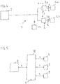
- the FIG. 1 shows a block diagram of a first embodiment of an autonomous wireless sensor device according to the invention.
- This sensor device 1 has a power source 2, a DC-DC converter assembly 3 and power sinks 4a and 4b.
- the energy source 2 is an energy collector, which has photovoltaic cells in the illustrated embodiment.
- At the output of the power source 2 is a DC voltage or a rectified AC voltage available.
- This DC voltage is provided via a power manager, the impedance matching means 5 and a first DC-DC converter 6, a rechargeable energy storage 7 available and used to charge it.
- the impedance matching means 5 an adaptation of the internal resistance of the energy collector to the internal resistance of the first DC-DC converter is performed.
- the DC voltage provided at the output of the first DC-DC converter is used to charge the rechargeable energy store 7.
- This rechargeable energy store is preferably a rechargeable battery, for example a lithium-ion battery, or an energy store having capacitors, for example so-called super-caps.
- a DC-DC converter assembly 3 is connected, which has two parallel-arranged DC-DC converter 3a and 3b in the embodiment shown. Each of these DC-DC converters provides a different DC voltage at its output.
- An energy sink 4a is connected to the output of the DC voltage converter 3a, and an energy sink 4b is connected to the output of the DC voltage converter 3b.
- the DC voltage provided at the output of the DC voltage converter 3a corresponds to the minimum required DC supply voltage of the energy sink 4a.
- the provided at the output of the DC-DC converter 3b DC voltage corresponds to the minimum necessary DC supply voltage of the energy sink 4b.
- the minimum necessary DC supply voltage of the energy sink 4a is different from the minimum necessary DC supply voltage of the energy sink 4b.
- DC voltage converters provided in parallel with one another are used to convert a DC voltage provided by a rechargeable energy store 7 into a plurality of different DC voltages, wherein these different DC voltages are supply voltages which are minimally required by different components of a sensor device.
- FIG. 1 illustrated embodiment may be connected to the outputs of the DC-DC converter 3a and 3b, respectively, several different energy sinks whose minimum required DC supply voltage matches the DC voltage provided by the respective DC-DC converter.
- FIG. 1 illustrated embodiment Another alternative to that in the FIG. 1 illustrated embodiment is to provide three or more DC-DC converter arranged in parallel to provide three or more different DC voltages, each of which is provided to one or more energy sinks to provide them with the minimum required DC supply voltage required in each case.
- a switch 8 is provided between the DC-DC converter 3a and the power sink 4a, to which a control signal s is supplied.
- This control signal s is provided by a control unit 9.
- FIG. 1 it can be seen that between the DC-DC converter 3b and the power sink 4b, a further switch 8 is provided, to which also a control signal s provided by the control unit 9 is supplied.
- control signals s are provided by the control unit 9 when the respective energy sink is not currently needed.
- the control signal s for the energy sink 4a upstream switch 8 is then provided when the energy sink 4a is currently not needed.
- the power supply of the energy sink 4a is interrupted.
- the energy supply of the energy sink 4a is only resumed when the energy sink 4a is needed again.
- the control signal s for the switch 8 upstream of the power sink 4b is then provided when the power sink 4b is not currently needed.
- the power supply of the energy sink 4b is interrupted.
- the energy supply of the energy sink 4b is only resumed when the energy sink 4b is needed again.
- the interruption of the power supply of currently not required energy sinks can also be carried out by deactivating the DC voltage converter upstream of the energy sink which is not currently required.
- the power sink 4a upstream DC-DC converter 3a a control signal s is supplied.
- the DC sink 4b upstream of the power sink 4b is also supplied with a control signal s.
- the control signal s for the DC voltage converter 3a connected upstream of the energy sink 4a is provided by the control unit 9 when the energy sink 4a is currently not needed. By this control signal s, the DC-DC converter 3a is deactivated.
- the power supply of the energy sink 4a is interrupted.
- the energy supply of the energy sink 4a is resumed by a reactivation of the DC voltage converter 3a only when the energy sink 4a is needed again.
- the control signal s for the DC voltage converter 3b upstream of the power sink 4b is provided by the control unit 9 when the power sink 4b is not currently needed.
- the DC-DC converter 3b is deactivated.
- the energy supply of the energy sink 4b is interrupted.
- the energy supply of the energy sink 4b is resumed by a reactivation of the DC voltage converter 3b only when the energy sink 4b is needed again.
- the power supply of the control circuit 9 is in the FIG. 1 not shown. For example, it can be done directly from the power source 2.
- FIG. 2 shows a block diagram of a second embodiment of an autonomous wireless sensor device according to the invention.
- This sensor device 1 has a power source 2, a DC-DC converter assembly 3 and power sinks 4a and 4b.
- the energy source 2 is an energy collector, which has photovoltaic cells in the illustrated embodiment.
- At the output of the power source 2 is a DC voltage or a rectified AC voltage available.
- This DC voltage is provided via a power manager, the impedance matching means 5 and a first DC-DC converter 6, a rechargeable energy storage 7 available and used to charge it.
- the impedance matching means 5 an adaptation of the internal resistance of the energy collector to the internal resistance of the first DC-DC converter is performed.
- the DC voltage provided at the output of the first DC-DC converter is used to charge the rechargeable energy store 7.
- This rechargeable energy store is preferably a rechargeable battery, for example a lithium-ion battery, or an energy store having capacitors, for example so-called super-caps
- a DC-DC converter assembly 3 is connected, which has two series-connected DC-DC converter 3a and 3b in the embodiment shown. Each of these DC-DC converter provides a different DC voltage at its output, wherein the DC-DC converter 3b uses the DC voltage provided by the DC-DC converter 3a as an input voltage and converts it into another DC voltage, which differs from the DC voltage provided by the DC-DC converter 3a.
- An energy sink 4a is connected to the output of the DC voltage converter 3a, and an energy sink 4b is connected to the output of the DC voltage converter 3b.
- the DC voltage provided at the output of the DC voltage converter 3a corresponds to the minimum required DC supply voltage of the energy sink 4a.
- the DC voltage provided at the output of the DC-DC converter 3b corresponds to the minimum necessary DC supply voltage of the power sink 4b.
- the minimum necessary DC supply voltage of the energy sink 4a is different from the minimum necessary DC supply voltage of the energy sink 4b.
- series-connected DC-DC converters are used to convert a DC voltage provided by a rechargeable energy store 7 into a plurality of different DC voltages, wherein these DC voltages are supply voltages that are minimally required by different components of a sensor device.
- FIG. 2 illustrated embodiment may be connected to the outputs of the DC-DC converter 3a and 3b, respectively, several different energy sinks whose minimum required DC supply voltage matches the DC voltage provided by the respective DC-DC converter.
- FIG. 2 illustrated embodiment Another alternative to that in the FIG. 2 illustrated embodiment is to provide three or more series-connected DC-DC converter to provide three or more different DC voltages, each of which one or more energy sinks are provided to provide them with the respectively required minimum DC supply voltage.
- a switch 8 is provided between the DC-DC converter 3a and the power sink 4a, to which a control signal s is supplied.
- This control signal s is provided by a control unit 9.
- FIG. 1 it can be seen that between the DC-DC converter 3b and the power sink 4b, a further switch 8 is provided, to which also a control signal s provided by the control unit 9 is supplied.
- control signals s are provided by the control unit 9 when the respective energy sink is not currently needed.
- the control signal s is provided for the upstream of the energy sink 4a switch 8, when the energy sink 4a is currently not needed.
- the power supply of the energy sink 4a is interrupted.
- the energy supply the energy sink 4a is only resumed when the energy sink 4a is needed again.
- the control signal s for the switch 8 upstream of the power sink 4b is provided when the power sink 4b is not currently needed.
- the power supply of the energy sink 4b is interrupted.
- the energy supply of the energy sink 4b is only resumed when the energy sink 4b is needed again.
- the interruption of the power supply of currently not required energy sinks can also be carried out by deactivating the DC voltage converter upstream of the energy sink which is not currently required. This is in the FIG. 2 indicated by dashed lines.
- the power sink 4a upstream DC-DC converter 3a a control signal s is supplied.
- the DC sink 4b upstream of the power sink 4b is also supplied with a control signal s.
- the control signal s for the DC voltage converter 3a connected upstream of the power sink 4a is provided by the control unit 9 when the power sink 4a and also the power sink 4b are not currently required.
- the DC-DC converter 3a is deactivated. Thereby, the power supply of the energy sinks 4a and 4b is interrupted. The energy supply of the energy sinks 4a and 4b is resumed by a reactivation of the DC voltage converter 3a only when the energy sinks 4a and 4b are needed again.
- the control signal s for the DC voltage converter 3b upstream of the power sink 4b is provided by the control unit 9 when the power sink 4b is not currently needed. By this control signal s, the DC-DC converter 3b is deactivated. As a result, the power supply of the power sink 4b is interrupted.
- the energy supply of the energy sink 4b is resumed by a reactivation of the DC voltage converter 3b only when the energy sink 4b is needed again. This makes it possible to interrupt the power supply of the power sink 4b while maintaining the power supply of the power sink 4a.
- the power supply of the control circuit 9 is in the FIG. 2 not shown. For example, it can be done directly from the power source 2.
- FIG. 3 shows a block diagram of a third embodiment of an autonomous wireless sensor device according to the invention.
- This sensor device 1 has a power source 2, a DC-DC converter assembly 3 and power sinks 4a, 4b and 4c.
- the energy source 2 is an energy collector, which has photovoltaic cells in the illustrated embodiment.
- At the output of the power source 2 is a DC voltage or a rectified AC voltage available.
- This DC voltage is provided via a power manager, the impedance matching means 5 and a first DC-DC converter 6, a rechargeable energy storage 7 available and used to charge it.
- the impedance matching means 5 an adaptation of the internal resistance of the energy collector to the internal resistance of the first DC-DC converter is performed.
- the DC voltage provided at the output of the first DC-DC converter is used to charge the rechargeable energy store 7.
- This rechargeable energy store is preferably a rechargeable battery, for example a lithium-ion battery, or an energy store having capacitors, for example so-called super-caps.
- a DC-DC converter assembly 3 which has three DC-DC converters 3a, 3b and 3c in the embodiment shown. Each of these DC-DC converter provides a different DC voltage at its output, wherein the DC-DC converter 3b uses the DC voltage provided by the DC converter 3a as an input voltage and converts it into another DC voltage, which is different from that provided by the DC-DC converter 3a DC voltage and from the DC-DC converter 3c provided DC voltage is different.
- An energy sink 4a is connected to the output of the DC voltage converter 3a, an energy sink 4b to the output of the DC voltage converter 3b, and an energy sink 4c to the output of the DC voltage converter 3c.
- the DC voltage provided at the output of the DC voltage converter 3a corresponds to the minimum required DC supply voltage of the energy sink 4a.
- the DC voltage provided at the output of the DC-DC converter 3b corresponds to the minimum necessary DC supply voltage of the energy sink 4b.
- the DC voltage provided at the output of the DC-DC converter 3c corresponds to the minimum required DC supply voltage of the power sink 4c.
- the minimum necessary DC supply voltages of the energy sinks 4a, 4b and 4c are different from each other.
- FIG. 3 illustrated embodiment may be connected to the outputs of the DC-DC converter 3a, 3b and 3c also each have a plurality of different energy sinks whose minimum required DC supply voltage matches the DC voltage provided by the respective DC voltage converter.
- a switch 8 is provided between the DC-DC converter 3a and the power sink 4a, to which a control signal s is supplied.
- This control signal s is provided by a control unit 9.
- control signals s are provided by the control unit 9 when the respective energy sink is not currently needed.
- the control signal s for the energy sink 4a upstream switch 8 is then provided when the energy sink 4a is currently not needed.
- the power supply of the energy sink 4a is interrupted.
- the energy supply of the energy sink 4a is only resumed when the energy sink 4a is needed again.
- the control signal s for the switch 8 upstream of the power sink 4b is provided when the power sink 4b is not currently needed.
- the power supply of the energy sink 4b is interrupted.
- the energy supply of the energy sink 4b is only resumed when the energy sink 4b is needed again.
- the control signal s for the switch 8 upstream of the power sink 4c is provided when the power sink 4c is not currently needed. By this control signal s, the power supply of the energy sink 4c is interrupted. The energy supply of the energy sink 4c is only resumed when the energy sink 4b is needed again.
- the interruption of the power supply of currently not required energy sinks can also be carried out by deactivating the DC voltage converter upstream of the energy sink which is not currently required. This is in the FIG. 3 indicated by dashed lines.
- the power sink 4a upstream DC-DC converter 3a a control signal s is supplied.
- the DC sink 4b upstream of the power sink 4b is also supplied with a control signal s.
- the power sink 4c upstream switch 8 also a control signal s is supplied.
- the control signal s for the DC voltage converter 3a connected upstream of the power sink 4a is provided by the control unit 9 when the power sink 4a and also the power sink 4b are not currently required.
- the DC-DC converter 3a is deactivated.
- the power supply of the energy sinks 4a and 4b is interrupted.
- the energy supply of the energy sinks 4a and 4b is resumed by a reactivation of the DC voltage converter 3a only when the energy sinks 4a and 4b are needed again.
- the control signal s for the energy sink 4b upstream DC-DC converter 3b is provided by the control unit 9 when the power sink 4b is not needed. By this control signal s, the DC-DC converter 3b is deactivated.
- the energy supply of the energy sink 4b is interrupted.
- the energy supply of the energy sink 4b is resumed by a reactivation of the DC voltage converter 3b only when the energy sink 4b is needed again.
- the control signal s for the DC voltage converter 3c upstream of the power sink 4c is provided by the control unit 9 when the power sink 4c is not currently needed.
- the DC-DC converter 3c is deactivated.
- the energy supply of the energy sink 4c is interrupted.
- the energy supply of the energy sink 4c is resumed by a reactivation of the DC voltage converter 3c only when the energy sink 4c is needed again.
- the power supply of the control circuit 9 is in the FIG. 3 not shown. For example, it can be done directly from the power source 2.
- FIG. 4 shows a block diagram of a fourth embodiment of an autonomous wireless sensor device according to the invention.
- This sensor device 1 has a power source 2, a DC-DC converter assembly 3 and power sinks 4a and 4b.
- the energy source 2 is a primary battery.
- a DC voltage At the output of the power source 2 is a DC voltage, which is the DC-DC converter assembly 3 is provided.
- this DC-DC converter subassembly 3 has two DC-DC converters 3a and 3b arranged parallel to one another. Each of these DC-DC converters provides a different DC voltage at its output.
- An energy sink 4a is connected to the output of the DC voltage converter 3a, and an energy sink 4b is connected to the output of the DC voltage converter 3b.
- the DC voltage provided at the output of the DC voltage converter 3a corresponds to the minimum required DC supply voltage of the energy sink 4a.
- the DC voltage provided at the output of the DC-DC converter 3b corresponds to the minimum necessary DC supply voltage of the power sink 4b.
- the minimum necessary DC supply voltage of the energy sink 4a is different from the minimum necessary DC supply voltage of the energy sink 4b.
- parallel DC voltage converters are used to convert a DC voltage provided by a primary battery into a plurality of different DC voltages, wherein these different DC voltages are supply voltages that are minimally required by different components of a sensor device.
- FIG. 4 illustrated embodiment may be connected to the outputs of the DC-DC converter 3a and 3b, respectively, several different energy sinks whose minimum required DC supply voltage matches the DC voltage provided by the respective DC-DC converter.
- FIG. 4 illustrated embodiment Another alternative to that in the FIG. 4 illustrated embodiment is to provide three or more DC-DC converter arranged in parallel to provide three or more different DC voltages, each of which is provided to one or more energy sinks to provide them with the minimum required DC supply voltage required in each case.
- a switch 8 is provided between the DC-DC converter 3a and the power sink 4a, to which a control signal s is supplied.
- This control signal s is provided by a control unit 9.
- control signals s are provided by the control unit 9 when the respective energy sink is not needed.
- the control signal s for the upstream of the energy sink 4a switch 8 is then provided when the energy sink 4a is not needed.
- the power supply of the energy sink 4a is interrupted.
- the energy supply of the energy sink 4a is only resumed when the energy sink 4a is needed again becomes.
- the control signal s for the switch 8 upstream of the power sink 4b is then provided when the power sink 4b is not needed.
- the power supply of the energy sink 4b is interrupted.
- the energy supply of the energy sink 4b is only resumed when the energy sink 4b is needed again.
- the interruption of the power supply of currently not required energy sinks can also be carried out by deactivating the DC voltage converter upstream of the energy sink which is not currently required.
- the power sink 4a upstream DC-DC converter 3a a control signal s is supplied.
- the DC sink 4b upstream of the power sink 4b is also supplied with a control signal s.
- the control signal s for the DC voltage converter 3a connected upstream of the energy sink 4a is provided by the control unit 9 when the energy sink 4a is currently not needed. By this control signal s, the DC-DC converter 3a is deactivated.
- the power supply of the energy sink 4a is interrupted.
- the energy supply of the energy sink 4a is resumed by a reactivation of the DC voltage converter 3a only when the energy sink 4a is needed again.
- the control signal s for the DC voltage converter 3b upstream of the power sink 4b is provided by the control unit 9 when the power sink 4b is not currently needed.
- the DC-DC converter 3b is deactivated.
- the energy supply of the energy sink 4b is interrupted.
- the energy supply of the energy sink 4b is resumed by a reactivation of the DC voltage converter 3b only when the energy sink 4b is needed again.
- the power supply of the control circuit 9 is in the FIG. 4 not shown. For example, it can be done directly from the power source 2.
- the FIG. 5 shows a block diagram of an alternative embodiment for the shutdown of the power supply of currently unneeded energy sinks.
- the control unit 9 performs an integrated Circuit 10 to a control signal s.
- the integrated circuit 10 has an operating voltage connection U and three outputs. Each of these outputs is connected to a switch 8 and supplies this switch 8 with a control signal s. Each of the switches 8 is followed by an energy sink, not shown.
- the control signal s output by the control unit 9 the integrated circuit 10 is informed which of the energy sinks connected to the switches are currently not needed.
- the integrated circuit 10 implements this information and provides those switches 8, which are assigned to a currently not required Energysenke, a control signal s available, which brings the respective switch 8 in its non-conductive state, so that the power supply of the respective switch downstream Energy sink is interrupted. If, at a later time, one of the energy sinks whose operating voltage supply is interrupted is required again, the control unit 9 informs the integrated circuit 10 of this. This then provides the respective switch a control signal available, which brings it back into its conducting state, so that the energy supply of the respective energy sink is resumed.
- an energy collector has been described as an energy source, which has at least one photovoltaic cell.
- an energy collector can be used as an energy collector in each case another type of energy collector, for example, a so-called thermal harvester or an inductive harvester.
- the DC-DC converters of the DC-DC converter assembly 3 described above may be boost converters, buck converters, or series regulators, or a suitable combination of boost converter downconverters and series regulators.
- either a primary battery or an energy collector was used as the power source.
- a primary battery and one or more energy collectors was used as the energy source or to use several energy collectors as the energy source.
- the control unit 9 which is realized in the form of a microcomputer and has an internal analog-to-digital converter, is provided for measuring a power supply voltage.
- a voltage divider must be used to match the measured voltage to the voltage range of the analog-to-digital converter. Since these voltage measurements are only carried out at longer time intervals of, for example, a few minutes or a whole hour, said voltage divider can be interrupted in the periods in which the voltage measurements are not carried out, for example using an analog switching IC.
- the leakage current of a switch is usually smaller than the leakage current of a voltage divider. This reduces the overall leakage current and increases the life of a primary battery used as an energy source.
- the power supply of currently unneeded sensors is interrupted.
- Typical sensor electronics have an average power consumption that is less than 100 ⁇ W.
- a critical component for the power consumption of an autonomous wireless sensor device are, for example, carbon dioxide sensors and volatile organic compound (VOC) sensors. Such sensors have power consumption for most of the time that is greater than 100 mW during active sensor operation and greater than 20 ⁇ W even in a low power mode.
- VOC volatile organic compound
- Such sensors have power consumption for most of the time that is greater than 100 mW during active sensor operation and greater than 20 ⁇ W even in a low power mode.
- their power supply in the periods in which these sensors are not needed is interrupted.
- an LDO or a transistor can be used as a switch. This switch can be controlled by a digital processor, which receives the necessary information from the outside via a wireless transmission link from a higher-level processor.
- the present invention reduces the power consumption of an autonomous wireless sensor device by interrupting the powering of currently unneeded components of the autonomous wireless sensor device during periods when they are not needed.
- These components include, for example, electronics that affect measurements, or functionalities such as an online software update.
- the supply voltages always consist in supplying these components with a supply voltage only if the respective component is required.
- a digital processor such as a microcomputer, a DSP or an FPGA, may be used for said power supply interruption. Any component critical to power consumption that does not have a power efficient low power mode may be disconnected from the power supply using such a switch when not needed.
- Turning on or off the power to an electronic component requires reconfiguration of the data interface to the digital processor, such as a microcomputer.
- the digital processor such as a microcomputer.
- the input / output terminals of the microcomputer are configured to have their normal operation function. If the respective component is to be turned off, however, then the said input / output terminals of the microcomputer must be switched high impedance.
Landscapes
- Engineering & Computer Science (AREA)
- Power Engineering (AREA)
- Computer Networks & Wireless Communication (AREA)
- Business, Economics & Management (AREA)
- Emergency Management (AREA)
- Charge And Discharge Circuits For Batteries Or The Like (AREA)
Abstract
Die Erfindung betrifft ein autonomes drahtloses Sensorgerät (1), welches eine Energiequelle (2), Energiesenken (4a, 4b, 4c) und Schaltmittel (8) aufweist, mittels derer die Energieversorgung momentan nicht benötigter Energiesenken unterbrechbar ist.The invention relates to an autonomous wireless sensor device (1) which has an energy source (2), energy sinks (4a, 4b, 4c) and switching means (8) by means of which the energy supply of energy sinks which are not currently required can be interrupted.
Description
Die Erfindung betrifft ein autonomes drahtloses Sensorgerät.The invention relates to an autonomous wireless sensor device.
Autonome drahtlose Sensorgeräte sind bereits bekannt. Sie weisen eine Energiequelle und Energiesenken auf. Bei der Energiequelle handelt es sich um eine Primärbatterie oder um einen Energiesammler. Energiesammler werden auch als Harvester bezeichnet. Zu diesen Harvestern gehören beispielsweise Photovoltaik-Harvester, Thermo-Harvester und induktive Harvester. Harvester-Energiequellen sind in den meisten Fällen über einen Powermanager und einen wiederaufladbaren Energiespeicher mit den Energiesenken des jeweiligen Sensorgerätes verbunden. Dieser Powermanager ist unter anderem dazu vorgesehen, eine Impedanzanpassung durchzuführen und eine Spannungsumsetzung vorzunehmen. Der Leistungsverbrauch eines autonomen drahtlosen Sensorgerätes kann aufgeteilt werden in aktive Leistung, die vom drahtlosen Sensorgerät benötigt wird, und Verlustleistung, die dann verbraucht wird, wenn das drahtlose Sensorgerät heruntergefahren ist und auf ein Ereignis wartet.Autonomous wireless sensor devices are already known. They have an energy source and energy sinks. The energy source is a primary battery or an energy collector. Energy collectors are also referred to as harvesters. These harvesters include, for example, photovoltaic harvesters, thermal harvesters and inductive harvesters. Harvester energy sources are connected in most cases via a power manager and a rechargeable energy storage with the energy sinks of the respective sensor device. This power manager is intended inter alia to perform an impedance matching and to carry out a voltage conversion. The power consumption of an autonomous wireless sensor device may be divided into active power required by the wireless sensor device and power dissipation that is consumed when the wireless sensor device is shut down and waiting for an event.
Die Aufgabe der Erfindung besteht darin, ein autonomes drahtloses Sensorgerät anzugeben, dessen Energieverbrauch reduziert ist.The object of the invention is to specify an autonomous wireless sensor device whose power consumption is reduced.
Diese Aufgabe wird durch ein autonomes drahtloses Sensorgerät mit den im Anspruch 1 angegebenen Merkmalen gelöst.This object is achieved by an autonomous wireless sensor device having the features specified in
Ein erfindungsgemäßes autonomes drahtloses Sensorgerät weist eine Energiequelle, Energiesenken und Schaltmittel auf, mittels derer die Energieversorgung momentan nicht benötigter Energiesenken unterbrechbar ist.An autonomous wireless sensor device according to the invention has an energy source, energy sinks and switching means, by means of which the energy supply of currently not required energy sinks can be interrupted.
Die Vorteile der Erfindung bestehen insbesondere darin, dass die Leistungseffizienz eines mit den erfindungsgemäßen Merkmalen ausgestatteten autonomen drahtlosen Sensorgerätes im Vergleich zu bekannten autonomen drahtlosen Sensorgeräten verbessert ist. Folglich benötigt ein mit den erfindungsgemäßen Merkmalen ausgestattetes autonomes drahtloses Sensorgerät weniger Leistung von der Energiequelle. Dies reduziert die Kosten eines autonomen drahtlosen Sensorgerätes, da kleinere Energiequellen und in dem Fall, dass ein Energiesammler als Energiequelle verwendet wird, auch kleinere wiederaufladbare Energiespeicher verwendet werden können.The advantages of the invention are, in particular, that the power efficiency of an autonomous wireless sensor device equipped with the features according to the invention is improved in comparison to known autonomous wireless sensor devices. Consequently, an autonomous wireless sensor device equipped with the features of the invention requires less power from the power source. This reduces the cost of an autonomous wireless sensor device, as smaller energy sources and, in the event that an energy collector is used as the power source, smaller rechargeable energy storage devices can be used.
Diese Vorteile werden im Wesentlichen dadurch erzielt, dass die Energieversorgung momentan nicht benötigter Energiesenken, beispielsweise momentan nicht benötigter Sensoren, momentan nicht benötigter Datenspeicher oder momentan nicht benötigter Messschaltungen des autonomen drahtlosen Sensorgerätes, unterbrochen wird und erst dann wieder hergestellt wird, wenn die nicht benötigte Energiesenke wieder benötigt wird.These advantages are achieved essentially by the fact that the energy supply currently not required energy sinks, for example currently not required sensors, currently not required data storage or currently not required measurement circuits of the autonomous wireless sensor device, is interrupted and only then restored when the unneeded Energiesenke is needed again.
Gemäß einer Ausführungsform der Erfindung weisen die Schaltmittel eine Steuereinheit auf, die zur Steuerung der Unterbrechung der Energieversorgung der momentan nicht benötigten Energiesenken ausgebildet ist. Dieser Steuereinheit liegen Informationen darüber vor, wann welche Energiesenke benötigt wird und wann sie nicht benötigt wird.According to one embodiment of the invention, the switching means have a control unit which is designed to control the interruption of the energy supply of the energy sinks not currently required. This control unit has information about when which energy sink is needed and when it is not needed.
Gemäß einer Ausführungsform der Erfindung weisen die Schaltmittel einen oder mehrere Schalter auf.According to one embodiment of the invention, the switching means comprise one or more switches.
Gemäß einer Ausführungsform der Erfindung ist den Energiesenken jeweils einer der Schalter vorgeschaltet.According to one embodiment of the invention, each of the energy sinks is preceded by one of the switches.
Gemäß einer Ausführungsform der Erfindung ist die Steuereinheit dazu ausgebildet, die Energieversorgung der momentan nicht benötigten Energiesenken durch eine Deaktivierung eines der jeweils nicht benötigten Energiesenke vorgeschalteten Gleichspannungswandlers zu unterbrechen. In diesem Falle sind den Energiesenken vorgeschaltete Schalter entbehrlich.In accordance with one embodiment of the invention, the control unit is designed to interrupt the power supply of the currently not required energy sinks by deactivating one of the respectively not required energy sinks upstream DC voltage converter. In this case, upstream of the energy sink switches are unnecessary.
Gemäß einer Ausführungsform der Erfindung ist die Steuereinheit dazu ausgebildet, einen zur Unterbrechung der Energieversorgung momentan nicht benötigter Energiesenken ausgebildeten integrierten Schaltkreis anzusteuern.According to one embodiment of the invention, the control unit is designed to control an integrated circuit designed to interrupt the energy supply of currently not required energy sinks.
Gemäß einer Ausführungsform der Erfindung ist den Energiesenken eine mehrere Gleichspannungswandler aufweisende Gleichspannungswandlerbaugruppe vorgeschaltet, wobei jede der Energiesenken an den Ausgang eines der Gleichspannungswandler angeschlossen ist.According to one embodiment of the invention, the power sink is preceded by a DC-DC converter assembly having a plurality of DC-DC converters, each of the power sinks being connected to the output of one of the DC-DC converters.
Gemäß einer Ausführungsform der Erfindung weist die Gleichspannungswandlerbaugruppe zwei oder mehr in Reihe geschaltete Gleichspannungswandler auf.According to one embodiment of the invention, the DC-DC converter assembly has two or more series-connected DC-DC converters.
Gemäß einer Ausführungsform der Erfindung weist die Gleichspannungswandlerbaugruppe zwei oder mehr parallel zueinander geschaltete Gleichspannungswandler auf.According to one embodiment of the invention, the DC-DC converter assembly has two or more DC-DC converters connected in parallel with each other.
Gemäß einer Ausführungsform der Erfindung ist die Energiequelle eine Primärbatterie.According to one embodiment of the invention, the energy source is a primary battery.
Gemäß einer Ausführungsform der Erfindung ist die Energiequelle ein Energiesammler.According to one embodiment of the invention, the energy source is an energy collector.
Gemäß einer Ausführungsform der Erfindung weist das autonome drahtlose Sensorgerät einen an den Energiesammler angeschlossenen Powermanager und einen an den Powermanager angeschlossenen wiederaufladbaren Energiespeicher auf, wobei der wiederaufladbare Energiespeicher über die Gleichspannungswandlerbaugruppe direkt oder über jeweils einen einer Energiesenke vorgeschalteten Schalter an die jeweilige Energiesenke angeschlossen ist.In accordance with one embodiment of the invention, the autonomous wireless sensor device has a power manager connected to the energy collector and a rechargeable energy store connected to the power manager, the rechargeable energy store being connected to the respective energy sink via the DC converter assembly directly or via a switch upstream of an energy sink.
Gemäß einer Ausführungsform der Erfindung weist der Powermanager Impedanzanpassungsmittel und einen Gleichspannungswandler auf und der Energiesammler ist über die Impedanzanpassungsmittel und den Gleichspannungswandler mit dem wiederaufladbaren Energiespeicher verbunden.According to one embodiment of the invention, the power manager has impedance matching means and a DC-DC converter, and the power collector is connected to the rechargeable energy storage via the impedance matching means and the DC-DC converter.
Gemäß einer Ausführungsform der Erfindung liegt der Gesamtenergiebedarf der Energiesenken im Bereich von 10 µW bis 1 mW.According to one embodiment of the invention, the total energy requirement of the energy sinks is in the range of 10 μW to 1 mW.
Gemäß einer Ausführungsform betrifft die Erfindung eine Verwendung eines autonomen drahtlosen Sensorgerätes im Bereich der Gebäudeautomation.According to one embodiment, the invention relates to a use of an autonomous wireless sensor device in the field of building automation.
-
Die
Figur 1 zeigt eine Blockdarstellung eines ersten Ausführungsbeispiels für ein autonomes drahtloses Sensorgerät gemäß der Erfindung.TheFIG. 1 shows a block diagram of a first embodiment of an autonomous wireless sensor device according to the invention. -
Die
Figur 2 zeigt eine Blockdarstellung eines zweiten Ausführungsbeispiels für ein autonomes drahtloses Sensorgerät gemäß der Erfindung.TheFIG. 2 shows a block diagram of a second embodiment of an autonomous wireless sensor device according to the invention. -
Die
Figur 3 zeigt eine Blockdarstellung eines dritten Ausführungsbeispiels für ein autonomes drahtloses Sensorgerät gemäß der Erfindung.TheFIG. 3 shows a block diagram of a third embodiment of an autonomous wireless sensor device according to the invention. -
Die
Figur 4 zeigt eine Blockdarstellung eines vierten Ausführungsbeispiels für ein autonomes drahtloses Sensorgerät gemäß der Erfindung.TheFIG. 4 shows a block diagram of a fourth embodiment of an autonomous wireless sensor device according to the invention. -
Die
Figur 5 zeigt eine Blockdarstellung einer alternativen Ausführungsform für die Abschaltung der Energieversorgung momentan nicht benötigter Energiesenken.TheFIG. 5 shows a block diagram of an alternative embodiment for the shutdown of the power supply of currently unneeded energy sinks.
Ein autonomes drahtloses Sensorgerät weist mehrere Energiesenken auf. Diese Energiesenken benötigen zu ihrem Betrieb eine Versorgungsgleichspannung, die unter Verwendung einer Energiequelle bereitgestellt wird. Mittels der vorliegenden Erfindung wird erreicht, dass der Energiebedarf des autonomen drahtlosen Sensorgerätes im Vergleich zu bekannten autonomen drahtlosen Sensorgeräten reduziert ist. Diese Reduzierung des Energiebedarfs des autonomen drahtlosen Sensorgerätes wird dadurch erreicht, dass die Energieversorgung momentan nicht benötigter Energiesenken des autonomen drahtlosen Sensorgerätes unterbrochen wird und erst dann wieder aktiviert wird, wenn die jeweilige Funktionalität wieder benötigt wird.An autonomous wireless sensor device has multiple energy sinks. These energy sinks require for their operation a DC supply voltage which is provided using a power source. By means of the present invention it is achieved that the energy requirement of the autonomous wireless sensor device is reduced compared to known autonomous wireless sensor devices. This reduction of the energy requirement of the autonomous wireless sensor device is achieved by interrupting the energy supply of currently not required energy sinks of the autonomous wireless sensor device and only reactivating it when the respective functionality is needed again.
Zu den genannten Energiesenken eines autonomen drahtlosen Sensorgerätes gehören insbesondere verschiedene Sensoren, Datenspeicher und Messschaltungen. Zu den Sensoren gehören beispielsweise ein Temperatursensor, ein Drucksensor, ein Feuchtigkeitssensor, ein Helligkeitssensor, ein Gassensor, ein Partikelsensor, ein akustischer Sensor, ein Magnetfeldsensor, ein Bewegungsdetektor und/oder ein oder mehrere mikroelektromechanische weitere Sensoren. Beispielsweise werden bestimmte Datenspeicher des autonomen drahtlosen Sensorgerätes nur dann benötigt, wenn ein Online-Software-Update eines Arbeitsprogrammes erfolgen soll.The aforementioned energy sinks of an autonomous wireless sensor device include, in particular, various sensors, data memories and measuring circuits. The sensors include, for example, a temperature sensor, a pressure sensor, a humidity sensor, a brightness sensor, a gas sensor, a particle sensor, an acoustic sensor, a magnetic field sensor, a motion detector, and / or one or more other microelectromechanical sensors. For example, certain data memories of the autonomous wireless sensor device are only required if an online software update of a work program is to take place.
Die Energieversorgung dieser Datenspeicher erfolgt nur für den Zeitraum dieses Online-Software-Updates. Ist dieses Online-Software-Update beendet, dann wird die Energieversorgung dieser Datenspeicher wieder unterbrochen.The power supply of this data storage takes place only for the period of this online software update. If this online software update is finished, the power supply of this data memory is interrupted again.
Ein Sensorgerät gemäß der Erfindung ist vorzugsweise zu einer Verwendung im Bereich der Gebäudeautomation ausgebildet. Bei einem derartigen Sensorgerät handelt es sich um ein Niedrigenergiegerät, dessen gesamter Leistungsbedarf im Bereich von 10 µW bis 1mW liegt.A sensor device according to the invention is preferably designed for use in the field of building automation. Such a sensor device is a low-energy device whose total power requirement is in the range of 10 μW to 1 mW.
Die
An den Ausgang des wiederaufladbaren Energiespeichers 7 ist eine Gleichspannungswandlerbaugruppe 3 angeschlossen, die beim gezeigten Ausführungsbeispiel zwei parallel zueinander angeordnete Gleichspannungswandler 3a und 3b aufweist. Jeder dieser Gleichspannungswandler stellt an seinem Ausgang eine andere Gleichspannung zur Verfügung.To the output of the
An den Ausgang des Gleichspannungswandlers 3a ist eine Energiesenke 4a angeschlossen, an den Ausgang des Gleichspannungswandlers 3b eine Energiesenke 4b. Die am Ausgang des Gleichspannungswandlers 3a bereitgestellte Gleichspannung entspricht der minimal notwendigen Versorgungsgleichspannung der Energiesenke 4a. Die am Ausgang des Gleichspannungswandlers 3b bereitgestellte Gleichspannung entspricht der minimal notwendigen Versorgungsgleichspannung der Energiesenke 4b.An energy sink 4a is connected to the output of the
Die minimal notwendige Versorgungsgleichspannung der Energiesenke 4a ist von der minimal notwendigen Versorgungsgleichspannung der Energiesenke 4b verschieden.The minimum necessary DC supply voltage of the energy sink 4a is different from the minimum necessary DC supply voltage of the
Folglich werden bei dem in der
Alternativ zu dem in der
Eine weitere Alternative zu dem in der
Des Weiteren ist aus der
Ferner ist aus der
Diese Steuersignale s werden von der Steuereinheit 9 dann bereitgestellt, wenn die jeweilige Energiesenke momentan nicht benötigt wird. So wird das Steuersignal s für den der Energiesenke 4a vorgeschalteten Schalter 8 dann bereitgestellt, wenn die Energiesenke 4a momentan nicht benötigt wird. Durch dieses Steuersignal s wird die Energieversorgung der Energiesenke 4a unterbrochen. Die Energieversorgung der Energiesenke 4a wird erst dann wieder aufgenommen, wenn die Energiesenke 4a wieder benötigt wird. Das Steuersignal s für den der Energiesenke 4b vorgeschalteten Schalter 8 dann bereitgestellt, wenn die Energiesenke 4b momentan nicht benötigt wird. Durch dieses Steuersignal s wird die Energieversorgung der Energiesenke 4b unterbrochen. Die Energieversorgung der Energiesenke 4b wird erst dann wieder aufgenommen, wenn die Energiesenke 4b wieder benötigt wird.These control signals s are provided by the
Durch diese Unterbrechung der Energieversorgung momentan nicht benötigter Energiesenken wird der Gesamtenergiebedarf des autonomen drahtlosen Sensorgerätes in vorteilhafter Weise reduziert.Through this interruption of the energy supply currently not required energy sinks, the total energy demand of the autonomous wireless sensor device is reduced in an advantageous manner.
Alternativ zu der Verwendung der Schalter 8 kann die Unterbrechung der Energieversorgung momentan nicht benötigter Energiesenken auch dadurch vorgenommen werden, dass der der momentan nicht benötigten Energiesenke vorgeschaltete Gleichspannungswandler deaktiviert wird. Dies ist in der
Die Energieversorgung der Steuerschaltung 9 ist in der
Die
An den Ausgang des wiederaufladbaren Energiespeichers 7 ist eine Gleichspannungswandlerbaugruppe 3 angeschlossen, die beim gezeigten Ausführungsbeispiel zwei in Reihe hintereinander angeordnete Gleichspannungswandler 3a und 3b aufweist. Jeder dieser Gleichspannungswandler stellt an seinem Ausgang eine andere Gleichspannung zur Verfügung, wobei der Gleichspannungswandler 3b die vom Gleichspannungswandler 3a bereitgestellte Gleichspannung als Eingangsspannung verwendet und diese in eine andere Gleichspannung wandelt, die sich von der vom Gleichspannungswandler 3a bereitgestellten Gleichspannung unterscheidet.To the output of the
An den Ausgang des Gleichspannungswandlers 3a ist eine Energiesenke 4a angeschlossen, an den Ausgang des Gleichspannungswandlers 3b eine Energiesenke 4b. Die am Ausgang des Gleichspannungswandlers 3a bereitgestellte Gleichspannung entspricht der minimal notwendigen Versorgungsgleichspannung der Energiesenke 4a. Die am Ausgang des Gleichspannungswandlers 3b bereitgestellte Gleichspannung entspricht der minimal notwendigen Versorgungsgleichspannung der Energiesenke 4b.An energy sink 4a is connected to the output of the
Die minimal notwendige Versorgungsgleichspannung der Energiesenke 4a ist von der minimal notwendigen Versorgungsgleichspannung der Energiesenke 4b verschieden.The minimum necessary DC supply voltage of the energy sink 4a is different from the minimum necessary DC supply voltage of the
Folglich werden bei dem in der
Alternativ zu dem in der
Eine weitere Alternative zu dem in der
Des Weiteren ist aus der
Ferner ist aus der
Diese Steuersignale s werden von der Steuereinheit 9 dann bereitgestellt, wenn die jeweilige Energiesenke momentan nicht benötigt wird. So wird das Steuersignal s für den der Energiesenke 4a vorgeschalteten Schalter 8 dann bereitgestellt, wenn die Energiesenke 4a momentan nicht benötigt wird. Durch dieses Steuersignal s wird die Energieversorgung der Energiesenke 4a unterbrochen. Die Energieversorgung der Energiesenke 4a wird erst dann wieder aufgenommen, wenn die Energiesenke 4a wieder benötigt wird. Das Steuersignal s für den der Energiesenke 4b vorgeschalteten Schalter 8 wird dann bereitgestellt, wenn die Energiesenke 4b momentan nicht benötigt wird. Durch dieses Steuersignal s wird die Energieversorgung der Energiesenke 4b unterbrochen. Die Energieversorgung der Energiesenke 4b wird erst dann wieder aufgenommen, wenn die Energiesenke 4b wieder benötigt wird.These control signals s are provided by the
Durch diese Unterbrechung der Energieversorgung momentan nicht benötigter Energiesenken wird der Gesamtenergiebedarf des autonomen drahtlosen Sensorgerätes in vorteilhafter Weise reduziert.Through this interruption of the energy supply currently not required energy sinks, the total energy demand of the autonomous wireless sensor device is reduced in an advantageous manner.
Alternativ zu der Verwendung der Schalter 8 kann die Unterbrechung der Energieversorgung momentan nicht benötigter Energiesenken auch dadurch vorgenommen werden, dass der der momentan nicht benötigten Energiesenke vorgeschaltete Gleichspannungswandler deaktiviert wird. Dies ist in der
Die Energieversorgung der Steuerschaltung 9 ist in der
Die
An den Ausgang des wiederaufladbaren Energiespeichers 7 ist eine Gleichspannungswandlerbaugruppe 3 angeschlossen, die beim gezeigten Ausführungsbeispiel drei Gleichspannungswandler 3a, 3b und 3c aufweist. Jeder dieser Gleichspannungswandler stellt an seinem Ausgang eine andere Gleichspannung zur Verfügung, wobei der Gleichspannungswandler 3b die vom Gleichspannungswandler 3a bereitgestellte Gleichspannung als Eingangsspannung verwendet und diese in eine andere Gleichspannung wandelt, die sich von der vom Gleichspannungswandler 3a bereitgestellten Gleichspannung und auch von der vom Gleichspannungswandler 3c bereitgestellten Gleichspannung unterscheidet.To the output of the
An den Ausgang des Gleichspannungswandlers 3a ist eine Energiesenke 4a angeschlossen, an den Ausgang des Gleichspannungswandlers 3b eine Energiesenke 4b und an den Ausgang des Gleichspannungswandlers 3c eine Energiesenke 4c. Die am Ausgang des Gleichspannungswandlers 3a bereitgestellte Gleichspannung entspricht der minimal notwendigen Versorgungsgleichspannung der Energiesenke 4a. Die am Ausgang des Gleichspannungswandlers 3b bereitgestellte Gleichspannung entspricht der minimal notwendigen Versorgungsgleichspannung der Energiesenke 4b. Die am Ausgang des Gleichspannungswandlers 3c bereitgestellte Gleichspannung entspricht der minimal notwendigen Versorgungsgleichspannung der Energiesenke 4c.An energy sink 4a is connected to the output of the
Die minimal notwendigen Versorgungsgleichspannungen der Energiesenken 4a, 4b und 4c sind voneinander verschieden.The minimum necessary DC supply voltages of the
Folglich werden bei dem in der
Alternativ zu dem in der
Des Weiteren ist aus der
Ferner ist aus der
Darüber hinaus ist aus der
Diese Steuersignale s werden von der Steuereinheit 9 dann bereitgestellt, wenn die jeweilige Energiesenke momentan nicht benötigt wird. So wird das Steuersignal s für den der Energiesenke 4a vorgeschalteten Schalter 8 dann bereitgestellt, wenn die Energiesenke 4a momentan nicht benötigt wird. Durch dieses Steuersignal s wird die Energieversorgung der Energiesenke 4a unterbrochen. Die Energieversorgung der Energiesenke 4a wird erst dann wieder aufgenommen, wenn die Energiesenke 4a wieder benötigt wird. Das Steuersignal s für den der Energiesenke 4b vorgeschalteten Schalter 8 wird dann bereitgestellt, wenn die Energiesenke 4b momentan nicht benötigt wird. Durch dieses Steuersignal s wird die Energieversorgung der Energiesenke 4b unterbrochen. Die Energieversorgung der Energiesenke 4b wird erst dann wieder aufgenommen, wenn die Energiesenke 4b wieder benötigt wird. Das Steuersignal s für den der Energiesenke 4c vorgeschalteten Schalter 8 wird dann bereitgestellt, wenn die Energiesenke 4c momentan nicht benötigt wird. Durch dieses Steuersignal s wird die Energieversorgung der Energiesenke 4c unterbrochen. Die Energieversorgung der Energiesenke 4c wird erst dann wieder aufgenommen, wenn die Energiesenke 4b wieder benötigt wird.These control signals s are provided by the
Durch diese Unterbrechung der Energieversorgung momentan nicht benötigter Energiesenken wird der Gesamtenergiebedarf des autonomen drahtlosen Sensorgerätes in vorteilhafter Weise reduziert.Through this interruption of the energy supply currently not required energy sinks, the total energy demand of the autonomous wireless sensor device is reduced in an advantageous manner.
Alternativ zu der Verwendung der Schalter 8 kann die Unterbrechung der Energieversorgung momentan nicht benötigter Energiesenken auch dadurch vorgenommen werden, dass der der momentan nicht benötigten Energiesenke vorgeschaltete Gleichspannungswandler deaktiviert wird. Dies ist in der
Das Steuersignal s für den der Energiesenke 4a vorgeschalteten Gleichspannungswandler 3a wird von der Steuereinheit 9 dann bereitgestellt, wenn die Energiesenke 4a und auch die Energiesenke 4b momentan nicht benötigt werden. Durch dieses Steuersignal s wird der Gleichspannungswandler 3a deaktiviert. Dadurch wird auch die Energieversorgung der Energiesenken 4a und 4b unterbrochen. Die Energieversorgung der Energiesenken 4a und 4b wird durch eine Reaktivierung des Gleichspannungswandlers 3a erst dann wieder aufgenommen, wenn die Energiesenken 4a und 4b wieder benötigt werden. Das Steuersignal s für den der Energiesenke 4b vorgeschalteten Gleichspannungswandler 3b wird von der Steuereinheit 9 dann bereitgestellt, wenn die Energiesenke 4b nicht benötigt wird. Durch dieses Steuersignal s wird der Gleichspannungswandler 3b deaktiviert. Dadurch wird auch die Energieversorgung der Energiesenke 4b unterbrochen. Die Energieversorgung der Energiesenke 4b wird durch eine Reaktivierung des Gleichspannungswandlers 3b erst dann wieder aufgenommen, wenn die Energiesenke 4b wieder benötigt wird. Dies ermöglicht es, die Energieversorgung der Energiesenke 4b bei Aufrechterhaltung der Energieversorgung der Energiesenke 4a zu unterbrechen. Das Steuersignal s für den der Energiesenke 4c vorgeschalteten Gleichspannungswandler 3c wird von der Steuereinheit 9 dann bereitgestellt, wenn die Energiesenke 4c momentan nicht benötigt wird. Durch dieses Steuersignal s wird der Gleichspannungswandler 3c deaktiviert. Dadurch wird auch die Energieversorgung der Energiesenke 4c unterbrochen. Die Energieversorgung der Energiesenke 4c wird durch eine Reaktivierung des Gleichspannungswandlers 3c erst dann wieder aufgenommen, wenn die Energiesenke 4c wieder benötigt wird.The control signal s for the
Die Energieversorgung der Steuerschaltung 9 ist in der
Die
An den Ausgang des Gleichspannungswandlers 3a ist eine Energiesenke 4a angeschlossen, an den Ausgang des Gleichspannungswandlers 3b eine Energiesenke 4b. Die am Ausgang des Gleichspannungswandlers 3a bereitgestellte Gleichspannung entspricht der minimal notwendigen Versorgungsgleichspannung der Energiesenke 4a. Die am Ausgang des Gleichspannungswandlers 3b bereitgestellte Gleichspannung entspricht der minimal notwendigen Versorgungsgleichspannung der Energiesenke 4b.An energy sink 4a is connected to the output of the
Die minimal notwendige Versorgungsgleichspannung der Energiesenke 4a ist von der minimal notwendigen Versorgungsgleichspannung der Energiesenke 4b verschieden.The minimum necessary DC supply voltage of the energy sink 4a is different from the minimum necessary DC supply voltage of the
Folglich werden bei dem in der
Alternativ zu dem in der
Eine weitere Alternative zu dem in der
Des Weiteren ist aus der
Ferner ist aus der
Diese Steuersignale s werden von der Steuereinheit 9 dann bereitgestellt, wenn die jeweilige Energiesenke nicht benötigt wird. So wird das Steuersignal s für den der Energiesenke 4a vorgeschalteten Schalter 8 dann bereitgestellt, wenn die Energiesenke 4a nicht benötigt wird. Durch dieses Steuersignal s wird die Energieversorgung der Energiesenke 4a unterbrochen. Die Energieversorgung der Energiesenke 4a wird erst dann wieder aufgenommen, wenn die Energiesenke 4a wieder benötigt wird. Das Steuersignal s für den der Energiesenke 4b vorgeschalteten Schalter 8 dann bereitgestellt, wenn die Energiesenke 4b nicht benötigt wird. Durch dieses Steuersignal s wird die Energieversorgung der Energiesenke 4b unterbrochen. Die Energieversorgung der Energiesenke 4b wird erst dann wieder aufgenommen, wenn die Energiesenke 4b wieder benötigt wird.These control signals s are provided by the
Durch diese Unterbrechung der Energieversorgung momentan nicht benötigter Energiesenken wird der Gesamtenergiebedarf des autonomen drahtlosen Sensorgerätes in vorteilhafter Weise reduziert.Through this interruption of the energy supply currently not required energy sinks, the total energy demand of the autonomous wireless sensor device is reduced in an advantageous manner.
Alternativ zu der Verwendung der Schalter 8 kann die Unterbrechung der Energieversorgung momentan nicht benötigter Energiesenken auch dadurch vorgenommen werden, dass der der momentan nicht benötigten Energiesenke vorgeschaltete Gleichspannungswandler deaktiviert wird. Dies ist in der
Die Energieversorgung der Steuerschaltung 9 ist in der
Die
Bei den oben anhand der
Bei den oben beschriebenen Gleichspannungswandlern der Gleichspannungswandlerbaugruppe 3 kann es sich um Aufwärtswandler, Abwärtswandler oder Längsregler oder um eine jeweils geeignete Kombination von Aufwärtswandlern Abwärtswandlern und Längsreglern handeln.The DC-DC converters of the DC-
Bei den oben beschriebenen Ausführungsbeispielen wurde entweder eine Primärbatterie oder ein Energiesammler als Energiequelle verwendet. Alternativ dazu ist es auch möglich, als Energiequelle eine Primärbatterie und einen oder mehrere Energiesammler zu verwenden oder als Energiequelle mehrere Energiesammler zu verwenden.In the embodiments described above, either a primary battery or an energy collector was used as the power source. Alternatively, it is also possible to use a primary battery and one or more energy collectors as the energy source or to use several energy collectors as the energy source.
Die vorstehend beschriebene Erfindung kann beispielsweise auch in den folgenden weiteren Anwendungsfällen verwendet werden:
In einem ersten weiteren Anwendungsfall ist die Steuereinheit 9, die in Form eines Mikrocomputers realisiert ist und einen internen Analog-Digital-Wandler aufweist, zur Messung einer Energieversorgungsspannung vorgesehen. Solange die Versorgungsspannung der Steuereinheit selbst kleiner ist als die von der Energiequelle 2 bereitgestellte Versorgungsspannung muss ein Spannungsteiler verwendet werden, um die gemessene Spannung an den Spannungsbereich des Analog-DigitalWandlers anzupassen. Da diese Spannungsmessungen nur in größeren zeitlichen Abständen von beispielsweise einigen Minuten oder einer ganzen Stunde durchgeführt werden, kann der genannte Spannungsteiler in den Zeiträumen, in denen die Spannungsmessungen nicht durchgeführt werden, unterbrochen werden, beispielsweise unter Verwendung eines analogen Schalt-ICs. In diesen Zeiträumen, in denen die Spannungsversorgung des Spannungsteilers unterbrochen ist, fließt lediglich der Leckstrom des Schalters, nicht aber der Leckstrom des Spannungsteilers. Der Leckstrom eines Schalters ist üblicherweise kleiner als der Leckstrom eines Spannungsteilers. Dadurch wird der insgesamt fließende Leckstrom reduziert und die Lebensdauer einer als Energiequelle verwendeten Primärbatterie erhöht.The invention described above can also be used, for example, in the following further applications:
In a first further application, the
In einem zweiten weiteren Anwendungsfall wird die Energieversorgung momentan nicht benötigter Sensoren unterbrochen. Eine typische Sensorelektronik hat einen durchschnittlichen Leistungsverbrauch, der kleiner ist als 100 µW. Eine kritische Komponente für den Leistungsverbrauch eines autonomen drahtlosen Sensorgerätes sind beispielsweise Kohlendioxid-sensoren und VOC-Sensoren (volatile organic compound). Derartige Sensoren haben für die meiste Zeit einen Leistungsverbrauch, der im aktiven Betrieb des Sensors größer ist als 100 mW und selbst in einem Niedrigenergiemodus größer ist als 20 µW. Um den Leckstrom in den Zeiträumen, in denen die genannten Sensoren nicht benötigt werden, zu reduzieren, wird gemäß der vorliegenden Erfindung deren Spannungsversorgung in den Zeiträumen, in denen diese Sensoren nicht benötigt werden, unterbrochen. Dabei kann beispielsweise ein LDO oder ein Transistor als Schalter benutzt werden. Dieser Schalter kann von einem digitalen Prozessor gesteuert werden, der die dazu notwendigen Informationen von außen über eine drahtlose Übertragungsstrecke von einem übergeordneten Prozessor erhält.In a second further application, the power supply of currently unneeded sensors is interrupted. Typical sensor electronics have an average power consumption that is less than 100 μW. A critical component for the power consumption of an autonomous wireless sensor device are, for example, carbon dioxide sensors and volatile organic compound (VOC) sensors. Such sensors have power consumption for most of the time that is greater than 100 mW during active sensor operation and greater than 20 μW even in a low power mode. In order to reduce the leakage current in the periods in which the said sensors are not required, according to the present invention, their power supply in the periods in which these sensors are not needed, is interrupted. In this case, for example, an LDO or a transistor can be used as a switch. This switch can be controlled by a digital processor, which receives the necessary information from the outside via a wireless transmission link from a higher-level processor.
Die vorliegende Erfindung reduziert nach alledem den Leistungsverbrauch eines autonomen drahtlosen Sensorgerätes dadurch, dass die Energieversorgung momentan nicht benötigter Komponenten des autonomen drahtlosen Sensorgerätes in den Zeiträumen, in denen sie nicht benötigt werden, unterbrochen wird. Zu diesen Komponenten gehören beispielsweise Elektroniken, die Messungen betreffen, oder Funktionalitäten wie ein online-Software-Update. Das Ziel dieser Unterbrechungen der Versorgungsspannungen besteht stets darin, diese Komponenten nur dann mit einer Versorgungsspannung zu versorgen, wenn die jeweilige Komponente benötigt wird. Zu der genannten Unterbrechung der Spannungsversorgung können beispielsweise ein oder mehrere Schalter verwendet werden, die von einem digitalen Prozessor gesteuert werden, beispielsweise einem Mikrocomputer, einem DSP oder einem FPGA. Jede in Bezug auf den Energieverbrauch kritische Komponente, die keinen leistungseffizienten Niedrigenergiemodus hat, kann unter Verwendung eines derartigen Schalters von der Energieversorgung abgetrennt werden, wenn sie nicht benötigt wird.The present invention, after all, reduces the power consumption of an autonomous wireless sensor device by interrupting the powering of currently unneeded components of the autonomous wireless sensor device during periods when they are not needed. These components include, for example, electronics that affect measurements, or functionalities such as an online software update. The goal of these interruptions The supply voltages always consist in supplying these components with a supply voltage only if the respective component is required. For example, one or more switches controlled by a digital processor, such as a microcomputer, a DSP or an FPGA, may be used for said power supply interruption. Any component critical to power consumption that does not have a power efficient low power mode may be disconnected from the power supply using such a switch when not needed.
Das Ein-oder Ausschalten der Spannungsversorgung einer elektronischen Komponente erfordert eine Rekonfiguration des Dateninterfaces zum digitalen Prozessor, beispielsweise einem Mikrocomputer. Beispielsweise werden dann, wenn eine dieser Komponenten wieder mit Energie versorgt werden soll, die Eingangs/Ausgangsanschlüsse des Mikrocomputers derart konfiguriert, dass sie ihre Normalbetriebsfunktion aufweisen. Wenn die jeweilige Komponente hingegen ausgeschaltet werden soll, dann müssen die genannten Eingangs/Ausgangsanschlüsse des Mikrocomputers hochohmig geschaltet werden.Turning on or off the power to an electronic component requires reconfiguration of the data interface to the digital processor, such as a microcomputer. For example, when one of these components is to be recharged, the input / output terminals of the microcomputer are configured to have their normal operation function. If the respective component is to be turned off, however, then the said input / output terminals of the microcomputer must be switched high impedance.
- 11
- Autonomes drahtloses SensorgerätAutonomous wireless sensor device
- 22
- Energiequelleenergy
- 33
- GleichspannungswandlerbaugruppeDC converter module
- 3a3a
- GleichspannungswandlerDC converter
- 3b3b
- GleichspannungswandlerDC converter
- 3c3c
- GleichspannungswandlerDC converter
- 4a4a
- Energiesenkeenergy sink
- 4b4b
- Energiesenkeenergy sink
- 4c4c
- Energiesenkeenergy sink
- 55
- ImpedanzanpassungsmittelImpedance matching means
- 66
- GleichspannungswandlerDC converter
- 77
- wiederaufladbarer Energiespeicherrechargeable energy storage
- 88th
- Schalterswitch
- 99
- Steuereinheitcontrol unit
- 1010
- Integrierter SchaltkreisIntegrated circuit
- SS
- Steuersignalcontrol signal
- UU
- SpannungsversorgungsanschlussPower Supply Connector
Claims (15)
Applications Claiming Priority (1)
| Application Number | Priority Date | Filing Date | Title |
|---|---|---|---|
| DE102018110784.6A DE102018110784A1 (en) | 2018-05-04 | 2018-05-04 | Autonomous wireless sensor device with reduced power consumption |
Publications (2)
| Publication Number | Publication Date |
|---|---|
| EP3565085A1 true EP3565085A1 (en) | 2019-11-06 |
| EP3565085B1 EP3565085B1 (en) | 2022-07-13 |
Family
ID=66334290
Family Applications (1)
| Application Number | Title | Priority Date | Filing Date |
|---|---|---|---|
| EP19171831.1A Active EP3565085B1 (en) | 2018-05-04 | 2019-04-30 | Autonomous wireless sensor device with reduced power consumption |
Country Status (2)
| Country | Link |
|---|---|
| EP (1) | EP3565085B1 (en) |
| DE (1) | DE102018110784A1 (en) |
Citations (3)
| Publication number | Priority date | Publication date | Assignee | Title |
|---|---|---|---|---|
| US20050017602A1 (en) * | 2003-03-05 | 2005-01-27 | Arms Steven W. | Shaft mounted energy harvesting for wireless sensor operation and data transmission |
| US20100060231A1 (en) * | 2006-01-05 | 2010-03-11 | Tpl, Inc. | Method and Apparatus for Energy Harvesting and/or Generation, Storage, and Delivery |
| US20150008872A1 (en) * | 2013-07-05 | 2015-01-08 | Hitachi, Ltd. | Autonomous Power Supply System |
Family Cites Families (6)
| Publication number | Priority date | Publication date | Assignee | Title |
|---|---|---|---|---|
| DE10125058B4 (en) * | 2001-05-22 | 2014-02-27 | Enocean Gmbh | Thermally fed transmitter and sensor system |
| DE10309334B4 (en) * | 2003-03-04 | 2006-12-07 | Enocean Gmbh | motion detector |
| US8552597B2 (en) * | 2006-03-31 | 2013-10-08 | Siemens Corporation | Passive RF energy harvesting scheme for wireless sensor |
| EP2199881B1 (en) * | 2008-12-18 | 2013-04-24 | Endress + Hauser Process Solutions AG | Field device for automation technology |
| AU2013221336B2 (en) * | 2012-02-17 | 2017-08-17 | University Of Virginia D/B/A University Of Virginia Licensing & Ventures Group | Energy harvesting and control for sensor node |
| US9912306B1 (en) * | 2016-08-12 | 2018-03-06 | Mediatek Inc. | Power supply circuit of wireless mobile device |
-
2018
- 2018-05-04 DE DE102018110784.6A patent/DE102018110784A1/en not_active Withdrawn
-
2019
- 2019-04-30 EP EP19171831.1A patent/EP3565085B1/en active Active
Patent Citations (3)
| Publication number | Priority date | Publication date | Assignee | Title |
|---|---|---|---|---|
| US20050017602A1 (en) * | 2003-03-05 | 2005-01-27 | Arms Steven W. | Shaft mounted energy harvesting for wireless sensor operation and data transmission |
| US20100060231A1 (en) * | 2006-01-05 | 2010-03-11 | Tpl, Inc. | Method and Apparatus for Energy Harvesting and/or Generation, Storage, and Delivery |
| US20150008872A1 (en) * | 2013-07-05 | 2015-01-08 | Hitachi, Ltd. | Autonomous Power Supply System |
Also Published As
| Publication number | Publication date |
|---|---|
| DE102018110784A1 (en) | 2019-11-07 |
| EP3565085B1 (en) | 2022-07-13 |
Similar Documents
| Publication | Publication Date | Title |
|---|---|---|
| DE102018206918B3 (en) | Hybrid buck-boost converter | |
| DE60218491T2 (en) | Battery with series-connected cells | |
| EP2368304B1 (en) | Energy storage assembly and method for operating such an assembly | |
| DE112020005154B4 (en) | CLOSED LOOP CONTROL RESERVE MANAGEMENT FOR BATTERIES CHARGING | |
| EP1090305A1 (en) | Device for testing solar home systems | |
| DE3031931A1 (en) | METHOD FOR MONITORING THE DRIVE BATTERY OF AN ELECTRIC VEHICLE | |
| EP0319941A1 (en) | Power supply method for solar cell powered electronic circuits, and arrangement for carrying out this method | |
| DE212008000035U1 (en) | High Frequency (HF) Inverter | |
| DE102014007548A1 (en) | Method for operating a vehicle electrical system of a motor vehicle and motor vehicle | |
| DE102010038941A1 (en) | Detection of a possible, but not actually fed, feed-in energy quantity of a photovoltaic system | |
| DE102005012663A1 (en) | Arrangement with a voltage converter for supplying power to an electrical load and method for adjusting the arrangement with voltage converter | |
| WO2010121896A1 (en) | Charging circuit for a charge accumulator and method for charging the same | |
| EP2504713B1 (en) | Load state determiner, load assembly, power supply circuit and method for determining a load state of an electrical power source | |
| DE112010005728T5 (en) | ELECTRICAL ADAPTER POWER INDICATION OF DESTINATION | |
| EP3565085B1 (en) | Autonomous wireless sensor device with reduced power consumption | |
| DE102009016759A1 (en) | Charge equalizing switch for lithium-ion battery pack for e.g. electric bicycle, has direct current to direct current converter designed such that charge is transferred from pair of connector clamps to another pair of clamps | |
| DE102018200379B4 (en) | Sensor arrangement and method for operating a sensor arrangement | |
| DE102009048670A1 (en) | Control device e.g. power monitoring device, for controlling power and quality of electrical network, has switching device monitoring power supply and switching power supplies during interference in energy storage mode | |
| DE102005033477B4 (en) | Circuit arrangement and method for converting an alternating voltage into a rectified voltage | |
| DE102013112988A1 (en) | Method for operating a DC / DC converter, via which a photovoltaic module is connected in series with other photovoltaic modules having a different characteristic, and a corresponding DC / DC converter and photovoltaic generator | |
| DE112018002809T5 (en) | POWER SUPPLY | |
| DE10008265A1 (en) | Electronic switch has battery switch and standby switch arranged in parallel with battery switch in form of semiconducting switch with two MOSFETs or PROFETs in series | |
| DE102019112782A1 (en) | Systems and methods for software configurable battery monitoring system | |
| EP3565086A1 (en) | Autonomous wireless sensor device | |
| WO2012163661A1 (en) | Circuit arrangement and method for operating an arrangement of energy stores, particularly of batteries |
Legal Events
| Date | Code | Title | Description |
|---|---|---|---|
| PUAI | Public reference made under article 153(3) epc to a published international application that has entered the european phase |
Free format text: ORIGINAL CODE: 0009012 |
|
| STAA | Information on the status of an ep patent application or granted ep patent |
Free format text: STATUS: THE APPLICATION HAS BEEN PUBLISHED |
|
| AK | Designated contracting states |
Kind code of ref document: A1 Designated state(s): AL AT BE BG CH CY CZ DE DK EE ES FI FR GB GR HR HU IE IS IT LI LT LU LV MC MK MT NL NO PL PT RO RS SE SI SK SM TR |
|
| AX | Request for extension of the european patent |
Extension state: BA ME |
|
| STAA | Information on the status of an ep patent application or granted ep patent |
Free format text: STATUS: REQUEST FOR EXAMINATION WAS MADE |
|
| 17P | Request for examination filed |
Effective date: 20200306 |
|
| RBV | Designated contracting states (corrected) |
Designated state(s): AL AT BE BG CH CY CZ DE DK EE ES FI FR GB GR HR HU IE IS IT LI LT LU LV MC MK MT NL NO PL PT RO RS SE SI SK SM TR |
|
| STAA | Information on the status of an ep patent application or granted ep patent |
Free format text: STATUS: EXAMINATION IS IN PROGRESS |
|
| 17Q | First examination report despatched |
Effective date: 20200616 |
|
| STAA | Information on the status of an ep patent application or granted ep patent |
Free format text: STATUS: EXAMINATION IS IN PROGRESS |
|
| GRAP | Despatch of communication of intention to grant a patent |
Free format text: ORIGINAL CODE: EPIDOSNIGR1 |
|
| STAA | Information on the status of an ep patent application or granted ep patent |
Free format text: STATUS: GRANT OF PATENT IS INTENDED |
|
| RIC1 | Information provided on ipc code assigned before grant |
Ipc: H02J 50/10 20160101ALI20220110BHEP Ipc: H02J 9/00 20060101ALI20220110BHEP Ipc: H02J 7/35 20060101AFI20220110BHEP |
|
| INTG | Intention to grant announced |
Effective date: 20220209 |
|
| GRAS | Grant fee paid |
Free format text: ORIGINAL CODE: EPIDOSNIGR3 |
|
| GRAA | (expected) grant |
Free format text: ORIGINAL CODE: 0009210 |
|
| STAA | Information on the status of an ep patent application or granted ep patent |
Free format text: STATUS: THE PATENT HAS BEEN GRANTED |
|
| RIN1 | Information on inventor provided before grant (corrected) |
Inventor name: BENISTON, JOHN Inventor name: RODENBUSCH-MOHR, THOMAS Inventor name: MENDOZA, FRANCISCO Inventor name: KAUL, HOLGER Inventor name: SOSALE, GURUPRASAD Inventor name: GEBHARDT, JOERG Inventor name: DECKER, ANDREAS Inventor name: AHREND, ULF |
|
| AK | Designated contracting states |
Kind code of ref document: B1 Designated state(s): AL AT BE BG CH CY CZ DE DK EE ES FI FR GB GR HR HU IE IS IT LI LT LU LV MC MK MT NL NO PL PT RO RS SE SI SK SM TR |
|
| RAP3 | Party data changed (applicant data changed or rights of an application transferred) |
Owner name: ABB SCHWEIZ AG |
|
| RIN1 | Information on inventor provided before grant (corrected) |
Inventor name: BENISTON, JOHN Inventor name: RODENBUSCH-MOHR, THOMAS Inventor name: MENDOZA, FRANCISCO Inventor name: KAUL, HOLGER Inventor name: SOSALE, GURUPRASAD Inventor name: GEBHARDT, JOERG Inventor name: DECKER, ANDREAS Inventor name: AHREND, ULF |
|
| REG | Reference to a national code |
Ref country code: CH Ref legal event code: EP |
|
| REG | Reference to a national code |
Ref country code: DE Ref legal event code: R096 Ref document number: 502019004940 Country of ref document: DE |
|
| REG | Reference to a national code |
Ref country code: AT Ref legal event code: REF Ref document number: 1504769 Country of ref document: AT Kind code of ref document: T Effective date: 20220815 |
|
| REG | Reference to a national code |
Ref country code: IE Ref legal event code: FG4D Free format text: LANGUAGE OF EP DOCUMENT: GERMAN |
|
| REG | Reference to a national code |
Ref country code: NL Ref legal event code: FP |
|
| REG | Reference to a national code |
Ref country code: LT Ref legal event code: MG9D |
|
| PG25 | Lapsed in a contracting state [announced via postgrant information from national office to epo] |
Ref country code: SE Free format text: LAPSE BECAUSE OF FAILURE TO SUBMIT A TRANSLATION OF THE DESCRIPTION OR TO PAY THE FEE WITHIN THE PRESCRIBED TIME-LIMIT Effective date: 20220713 Ref country code: RS Free format text: LAPSE BECAUSE OF FAILURE TO SUBMIT A TRANSLATION OF THE DESCRIPTION OR TO PAY THE FEE WITHIN THE PRESCRIBED TIME-LIMIT Effective date: 20220713 Ref country code: PT Free format text: LAPSE BECAUSE OF FAILURE TO SUBMIT A TRANSLATION OF THE DESCRIPTION OR TO PAY THE FEE WITHIN THE PRESCRIBED TIME-LIMIT Effective date: 20221114 Ref country code: NO Free format text: LAPSE BECAUSE OF FAILURE TO SUBMIT A TRANSLATION OF THE DESCRIPTION OR TO PAY THE FEE WITHIN THE PRESCRIBED TIME-LIMIT Effective date: 20221013 Ref country code: LV Free format text: LAPSE BECAUSE OF FAILURE TO SUBMIT A TRANSLATION OF THE DESCRIPTION OR TO PAY THE FEE WITHIN THE PRESCRIBED TIME-LIMIT Effective date: 20220713 Ref country code: LT Free format text: LAPSE BECAUSE OF FAILURE TO SUBMIT A TRANSLATION OF THE DESCRIPTION OR TO PAY THE FEE WITHIN THE PRESCRIBED TIME-LIMIT Effective date: 20220713 Ref country code: FI Free format text: LAPSE BECAUSE OF FAILURE TO SUBMIT A TRANSLATION OF THE DESCRIPTION OR TO PAY THE FEE WITHIN THE PRESCRIBED TIME-LIMIT Effective date: 20220713 Ref country code: ES Free format text: LAPSE BECAUSE OF FAILURE TO SUBMIT A TRANSLATION OF THE DESCRIPTION OR TO PAY THE FEE WITHIN THE PRESCRIBED TIME-LIMIT Effective date: 20220713 |
|
| PG25 | Lapsed in a contracting state [announced via postgrant information from national office to epo] |
Ref country code: PL Free format text: LAPSE BECAUSE OF FAILURE TO SUBMIT A TRANSLATION OF THE DESCRIPTION OR TO PAY THE FEE WITHIN THE PRESCRIBED TIME-LIMIT Effective date: 20220713 Ref country code: IS Free format text: LAPSE BECAUSE OF FAILURE TO SUBMIT A TRANSLATION OF THE DESCRIPTION OR TO PAY THE FEE WITHIN THE PRESCRIBED TIME-LIMIT Effective date: 20221113 Ref country code: HR Free format text: LAPSE BECAUSE OF FAILURE TO SUBMIT A TRANSLATION OF THE DESCRIPTION OR TO PAY THE FEE WITHIN THE PRESCRIBED TIME-LIMIT Effective date: 20220713 Ref country code: GR Free format text: LAPSE BECAUSE OF FAILURE TO SUBMIT A TRANSLATION OF THE DESCRIPTION OR TO PAY THE FEE WITHIN THE PRESCRIBED TIME-LIMIT Effective date: 20221014 |
|
| REG | Reference to a national code |
Ref country code: DE Ref legal event code: R097 Ref document number: 502019004940 Country of ref document: DE |
|
| PG25 | Lapsed in a contracting state [announced via postgrant information from national office to epo] |
Ref country code: SM Free format text: LAPSE BECAUSE OF FAILURE TO SUBMIT A TRANSLATION OF THE DESCRIPTION OR TO PAY THE FEE WITHIN THE PRESCRIBED TIME-LIMIT Effective date: 20220713 Ref country code: RO Free format text: LAPSE BECAUSE OF FAILURE TO SUBMIT A TRANSLATION OF THE DESCRIPTION OR TO PAY THE FEE WITHIN THE PRESCRIBED TIME-LIMIT Effective date: 20220713 Ref country code: DK Free format text: LAPSE BECAUSE OF FAILURE TO SUBMIT A TRANSLATION OF THE DESCRIPTION OR TO PAY THE FEE WITHIN THE PRESCRIBED TIME-LIMIT Effective date: 20220713 Ref country code: CZ Free format text: LAPSE BECAUSE OF FAILURE TO SUBMIT A TRANSLATION OF THE DESCRIPTION OR TO PAY THE FEE WITHIN THE PRESCRIBED TIME-LIMIT Effective date: 20220713 |
|
| PLBE | No opposition filed within time limit |
Free format text: ORIGINAL CODE: 0009261 |
|
| STAA | Information on the status of an ep patent application or granted ep patent |
Free format text: STATUS: NO OPPOSITION FILED WITHIN TIME LIMIT |
|
| PG25 | Lapsed in a contracting state [announced via postgrant information from national office to epo] |
Ref country code: SK Free format text: LAPSE BECAUSE OF FAILURE TO SUBMIT A TRANSLATION OF THE DESCRIPTION OR TO PAY THE FEE WITHIN THE PRESCRIBED TIME-LIMIT Effective date: 20220713 Ref country code: EE Free format text: LAPSE BECAUSE OF FAILURE TO SUBMIT A TRANSLATION OF THE DESCRIPTION OR TO PAY THE FEE WITHIN THE PRESCRIBED TIME-LIMIT Effective date: 20220713 |
|
| 26N | No opposition filed |
Effective date: 20230414 |
|
| PG25 | Lapsed in a contracting state [announced via postgrant information from national office to epo] |
Ref country code: AL Free format text: LAPSE BECAUSE OF FAILURE TO SUBMIT A TRANSLATION OF THE DESCRIPTION OR TO PAY THE FEE WITHIN THE PRESCRIBED TIME-LIMIT Effective date: 20220713 |
|
| PG25 | Lapsed in a contracting state [announced via postgrant information from national office to epo] |
Ref country code: SI Free format text: LAPSE BECAUSE OF FAILURE TO SUBMIT A TRANSLATION OF THE DESCRIPTION OR TO PAY THE FEE WITHIN THE PRESCRIBED TIME-LIMIT Effective date: 20220713 |
|
| REG | Reference to a national code |
Ref country code: CH Ref legal event code: PL |
|
| GBPC | Gb: european patent ceased through non-payment of renewal fee |
Effective date: 20230430 |
|
| PG25 | Lapsed in a contracting state [announced via postgrant information from national office to epo] |
Ref country code: LU Free format text: LAPSE BECAUSE OF NON-PAYMENT OF DUE FEES Effective date: 20230430 |
|
| REG | Reference to a national code |
Ref country code: BE Ref legal event code: MM Effective date: 20230430 |
|
| PG25 | Lapsed in a contracting state [announced via postgrant information from national office to epo] |
Ref country code: MC Free format text: LAPSE BECAUSE OF FAILURE TO SUBMIT A TRANSLATION OF THE DESCRIPTION OR TO PAY THE FEE WITHIN THE PRESCRIBED TIME-LIMIT Effective date: 20220713 |
|
| PG25 | Lapsed in a contracting state [announced via postgrant information from national office to epo] |
Ref country code: GB Free format text: LAPSE BECAUSE OF NON-PAYMENT OF DUE FEES Effective date: 20230430 |
|
| PG25 | Lapsed in a contracting state [announced via postgrant information from national office to epo] |
Ref country code: MC Free format text: LAPSE BECAUSE OF FAILURE TO SUBMIT A TRANSLATION OF THE DESCRIPTION OR TO PAY THE FEE WITHIN THE PRESCRIBED TIME-LIMIT Effective date: 20220713 Ref country code: LI Free format text: LAPSE BECAUSE OF NON-PAYMENT OF DUE FEES Effective date: 20230430 Ref country code: IT Free format text: LAPSE BECAUSE OF FAILURE TO SUBMIT A TRANSLATION OF THE DESCRIPTION OR TO PAY THE FEE WITHIN THE PRESCRIBED TIME-LIMIT Effective date: 20220713 Ref country code: GB Free format text: LAPSE BECAUSE OF NON-PAYMENT OF DUE FEES Effective date: 20230430 Ref country code: FR Free format text: LAPSE BECAUSE OF NON-PAYMENT OF DUE FEES Effective date: 20230430 Ref country code: CH Free format text: LAPSE BECAUSE OF NON-PAYMENT OF DUE FEES Effective date: 20230430 |
|
| REG | Reference to a national code |
Ref country code: IE Ref legal event code: MM4A |
|
| PG25 | Lapsed in a contracting state [announced via postgrant information from national office to epo] |
Ref country code: BE Free format text: LAPSE BECAUSE OF NON-PAYMENT OF DUE FEES Effective date: 20230430 |
|
| PG25 | Lapsed in a contracting state [announced via postgrant information from national office to epo] |
Ref country code: IE Free format text: LAPSE BECAUSE OF NON-PAYMENT OF DUE FEES Effective date: 20230430 |
|
| PG25 | Lapsed in a contracting state [announced via postgrant information from national office to epo] |
Ref country code: IE Free format text: LAPSE BECAUSE OF NON-PAYMENT OF DUE FEES Effective date: 20230430 |
|
| PGFP | Annual fee paid to national office [announced via postgrant information from national office to epo] |
Ref country code: NL Payment date: 20240418 Year of fee payment: 6 |
|
| PGFP | Annual fee paid to national office [announced via postgrant information from national office to epo] |
Ref country code: DE Payment date: 20240418 Year of fee payment: 6 |
|
| PGFP | Annual fee paid to national office [announced via postgrant information from national office to epo] |
Ref country code: AT Payment date: 20240419 Year of fee payment: 6 |
|
| PG25 | Lapsed in a contracting state [announced via postgrant information from national office to epo] |
Ref country code: BG Free format text: LAPSE BECAUSE OF FAILURE TO SUBMIT A TRANSLATION OF THE DESCRIPTION OR TO PAY THE FEE WITHIN THE PRESCRIBED TIME-LIMIT Effective date: 20220713 |
|
| PG25 | Lapsed in a contracting state [announced via postgrant information from national office to epo] |
Ref country code: BG Free format text: LAPSE BECAUSE OF FAILURE TO SUBMIT A TRANSLATION OF THE DESCRIPTION OR TO PAY THE FEE WITHIN THE PRESCRIBED TIME-LIMIT Effective date: 20220713 |