EP3564992A1 - Fluid-based cooling device for cooling at least two distinct first heat-generating elements of a heat source assembly - Google Patents
Fluid-based cooling device for cooling at least two distinct first heat-generating elements of a heat source assembly Download PDFInfo
- Publication number
- EP3564992A1 EP3564992A1 EP18170404.0A EP18170404A EP3564992A1 EP 3564992 A1 EP3564992 A1 EP 3564992A1 EP 18170404 A EP18170404 A EP 18170404A EP 3564992 A1 EP3564992 A1 EP 3564992A1
- Authority
- EP
- European Patent Office
- Prior art keywords
- fluid
- heat
- cooling device
- plate
- sink structure
- Prior art date
- Legal status (The legal status is an assumption and is not a legal conclusion. Google has not performed a legal analysis and makes no representation as to the accuracy of the status listed.)
- Granted
Links
- 239000012530 fluid Substances 0.000 title claims abstract description 254
- 238000001816 cooling Methods 0.000 title claims abstract description 159
- 239000012809 cooling fluid Substances 0.000 claims abstract description 89
- 239000000463 material Substances 0.000 claims description 12
- 239000002826 coolant Substances 0.000 description 20
- 239000007787 solid Substances 0.000 description 8
- 229910000838 Al alloy Inorganic materials 0.000 description 3
- 239000004519 grease Substances 0.000 description 2
- 238000010438 heat treatment Methods 0.000 description 2
- 239000004065 semiconductor Substances 0.000 description 2
- UJCHIZDEQZMODR-BYPYZUCNSA-N (2r)-2-acetamido-3-sulfanylpropanamide Chemical compound CC(=O)N[C@@H](CS)C(N)=O UJCHIZDEQZMODR-BYPYZUCNSA-N 0.000 description 1
- 241001669680 Dormitator maculatus Species 0.000 description 1
- 229910045601 alloy Inorganic materials 0.000 description 1
- 239000000956 alloy Substances 0.000 description 1
- XAGFODPZIPBFFR-UHFFFAOYSA-N aluminium Chemical compound [Al] XAGFODPZIPBFFR-UHFFFAOYSA-N 0.000 description 1
- 229910052782 aluminium Inorganic materials 0.000 description 1
- 230000001419 dependent effect Effects 0.000 description 1
- 238000011161 development Methods 0.000 description 1
- 230000018109 developmental process Effects 0.000 description 1
- 230000004907 flux Effects 0.000 description 1
- 238000001746 injection moulding Methods 0.000 description 1
- 238000003801 milling Methods 0.000 description 1
- 230000032258 transport Effects 0.000 description 1
Images


Classifications
-
- F—MECHANICAL ENGINEERING; LIGHTING; HEATING; WEAPONS; BLASTING
- F28—HEAT EXCHANGE IN GENERAL
- F28F—DETAILS OF HEAT-EXCHANGE AND HEAT-TRANSFER APPARATUS, OF GENERAL APPLICATION
- F28F3/00—Plate-like or laminated elements; Assemblies of plate-like or laminated elements
- F28F3/12—Elements constructed in the shape of a hollow panel, e.g. with channels
-
- F—MECHANICAL ENGINEERING; LIGHTING; HEATING; WEAPONS; BLASTING
- F28—HEAT EXCHANGE IN GENERAL
- F28F—DETAILS OF HEAT-EXCHANGE AND HEAT-TRANSFER APPARATUS, OF GENERAL APPLICATION
- F28F3/00—Plate-like or laminated elements; Assemblies of plate-like or laminated elements
- F28F3/02—Elements or assemblies thereof with means for increasing heat-transfer area, e.g. with fins, with recesses, with corrugations
- F28F3/06—Elements or assemblies thereof with means for increasing heat-transfer area, e.g. with fins, with recesses, with corrugations the means being attachable to the element
-
- H—ELECTRICITY
- H01—ELECTRIC ELEMENTS
- H01L—SEMICONDUCTOR DEVICES NOT COVERED BY CLASS H10
- H01L23/00—Details of semiconductor or other solid state devices
- H01L23/34—Arrangements for cooling, heating, ventilating or temperature compensation ; Temperature sensing arrangements
- H01L23/36—Selection of materials, or shaping, to facilitate cooling or heating, e.g. heatsinks
- H01L23/367—Cooling facilitated by shape of device
- H01L23/3672—Foil-like cooling fins or heat sinks
-
- H—ELECTRICITY
- H01—ELECTRIC ELEMENTS
- H01L—SEMICONDUCTOR DEVICES NOT COVERED BY CLASS H10
- H01L23/00—Details of semiconductor or other solid state devices
- H01L23/34—Arrangements for cooling, heating, ventilating or temperature compensation ; Temperature sensing arrangements
- H01L23/46—Arrangements for cooling, heating, ventilating or temperature compensation ; Temperature sensing arrangements involving the transfer of heat by flowing fluids
- H01L23/467—Arrangements for cooling, heating, ventilating or temperature compensation ; Temperature sensing arrangements involving the transfer of heat by flowing fluids by flowing gases, e.g. air
-
- H—ELECTRICITY
- H05—ELECTRIC TECHNIQUES NOT OTHERWISE PROVIDED FOR
- H05K—PRINTED CIRCUITS; CASINGS OR CONSTRUCTIONAL DETAILS OF ELECTRIC APPARATUS; MANUFACTURE OF ASSEMBLAGES OF ELECTRICAL COMPONENTS
- H05K7/00—Constructional details common to different types of electric apparatus
- H05K7/20—Modifications to facilitate cooling, ventilating, or heating
- H05K7/20009—Modifications to facilitate cooling, ventilating, or heating using a gaseous coolant in electronic enclosures
- H05K7/20136—Forced ventilation, e.g. by fans
- H05K7/20154—Heat dissipaters coupled to components
- H05K7/20163—Heat dissipaters coupled to components the components being isolated from air flow, e.g. hollow heat sinks, wind tunnels or funnels
-
- F—MECHANICAL ENGINEERING; LIGHTING; HEATING; WEAPONS; BLASTING
- F28—HEAT EXCHANGE IN GENERAL
- F28D—HEAT-EXCHANGE APPARATUS, NOT PROVIDED FOR IN ANOTHER SUBCLASS, IN WHICH THE HEAT-EXCHANGE MEDIA DO NOT COME INTO DIRECT CONTACT
- F28D21/00—Heat-exchange apparatus not covered by any of the groups F28D1/00 - F28D20/00
- F28D2021/0019—Other heat exchangers for particular applications; Heat exchange systems not otherwise provided for
- F28D2021/0028—Other heat exchangers for particular applications; Heat exchange systems not otherwise provided for for cooling heat generating elements, e.g. for cooling electronic components or electric devices
- F28D2021/0029—Heat sinks
-
- F—MECHANICAL ENGINEERING; LIGHTING; HEATING; WEAPONS; BLASTING
- F28—HEAT EXCHANGE IN GENERAL
- F28F—DETAILS OF HEAT-EXCHANGE AND HEAT-TRANSFER APPARATUS, OF GENERAL APPLICATION
- F28F2250/00—Arrangements for modifying the flow of the heat exchange media, e.g. flow guiding means; Particular flow patterns
- F28F2250/10—Particular pattern of flow of the heat exchange media
Definitions
- the invention relates to a fluid-based cooling device for cooling at least two distinct first heat-generating elements of a heat source assembly.
- the heat source assembly is in thermal contact with the fluid-based cooling device.
- the fluid-based cooling device comprises a first plate, a heat sink structure and a second plate.
- the first plate is configured for thermally contacting the heat source assembly.
- the heat sink structure is arranged on the first plate.
- the second plate is configured for directing a flow of a cooling fluid to the heat sink structure.
- the second plate is arranged on the heat sink structure.
- a state-of-the-art fluid heat exchanger for cooling an electronic device comprises a first plate in thermal contact with a heat generating element, a second plate having a fluid inlet opening and a heat sink structure comprising a plurality of fins arranged between the first and second plates.
- the fluid inlet opening of the second plate is arranged centered (or a little off-center) atop the heat sink structure to disperse a cooling fluid over the heat sink structure.
- the heat sink structure comprises an arrangement of parallel fins machined into the first plate. The parallel fins are arranged to form micro-channels between them allowing the cooling fluid to flow between them such that heat can be transferred from the first plate to the cooling fluid.
- Such a fluid-based cooling device is disclosed in US 8,746,330 B2 and US 2017/0196116 A1 .
- US 2008/0264604 A1 discloses a cooling apparatus for removing heat from an electronic device.
- the cooling apparatus comprises a manifold structure having a plurality of coolant inlet and outlet passageways interleaved in the manifold structure.
- the manifold structure further includes coolant inlet and outlet plenums, with cooling fluid passing through the inlet passageways from the inlet plenum in a first direction and cooling fluid passing through the outlet passageways to the outlet plenum in a second direction.
- the first and second directions are perpendicular to a surface to be cooled.
- WO 2004/042302 A2 discloses a fluid cooled channeled heat exchanger device comprising two flat coupled plates and a plurality of fins coupled to the two plates.
- One of the plates comprises a plurality of condenser channels configured to receive, to condense and to cool a cooling fluid in a heated state.
- GB 2 402 465 A discloses a split flow heat exchanger comprising a cylindrical chamber having an inlet communicating a heating fluid to a header and a heat transfer device comprising an enclosure with a plurality of tubes.
- Known fluid-based cooling devices fail to optimally cool a heat source assembly, e.g. a CPU or GPU assembly, comprising more than one distinct heat-generating elements, e.g. two or more CPU or GPU dies, when the distinct heat-generating elements are spatially separated from each other.
- a fluid-based cooling device for cooling at least two distinct first heat-generating elements of a heat source assembly.
- the heat source assembly is in thermal contact with the fluid-based cooling device.
- the fluid-based cooling device comprises a first plate, a heat sink structure and a second plate.
- the first plate is configured for thermally contacting the heat source assembly.
- the heat sink structure is arranged on or in the first plate.
- the second plate is configured for directing a flow of a cooling fluid to the heat sink structure.
- the second plate is arranged on the heat sink structure.
- the heat sink structure comprises at least two heat sink structure portions each corresponding to an associated one of the at least two distinct first heat-generating elements.
- the second plate comprises at least two fluid inlet opening regions, wherein each of the fluid inlet opening regions is associated with a corresponding heat sink structure portion of the at least two heat sink structure portions.
- Areas of the heat source assembly where the at least two first heat-generating elements are arranged constitute areas of high heat flux, i.e. they heat up more quickly than the remaining areas of the heat source assembly. Since the heat source assembly is in thermal contact with the first plate, the first plate will heat up more quickly in areas associated with the at least two first heat-generating elements.
- Each of the at least two heat sink structure portions is associated with at least one of the at least two distinct first heat-generating elements, e.g. arranged on the first plate atop the at least one heat-generating element.
- a cooling fluid is dispersed over the heat sink structure through the at least two fluid inlet opening regions.
- Each of the at least two fluid inlet opening regions is associated with a corresponding one of the at least two heat sink structure portions, so that the cooling fluid can selectively be provided for each of the at least two heat sink structure portions. Heat is transferred from each of the at least two heat sink structure portions to the cooling fluid heating the same up, thereby allowing to divert the heat away specifically from the areas of the heat source assembly where the at least two first heat-generating elements are arranged.
- the present invention thus allows for an optimal cooling of at least two spatially separated first heat-generating elements of a heat source assembly such as a multi-die CPU or GPU.
- a heat source assembly such as a multi-die CPU or GPU.
- the heat sink structure comprises a plurality of fins extending in parallel in a first direction.
- the fluid inlet opening regions longitudinally extend in a second direction perpendicular to the first direction. This allows for the cooling fluid to be evenly dispersed among the heat sink structure allowing for a uniform cooling of the first plate and thereby the heat source assembly.
- the fluid-based cooling device (including the first plate) has a rectangular shape having a long side and a short side.
- the long side of the fluid-based cooling device (or the first plate) is parallel to the first direction (i.e. parallel to the fins), while the short side of the fluid-based cooling device (or the first plate) is parallel to the second direction (i.e. perpendicular to the fins).
- the long side of the heat source assembly having a rectangular shape is parallel to the first direction
- the short side of the heat source assembly having the rectangular shape is parallel to the second direction.
- the short side of the fluid-based cooling device (or the first plate) may be parallel to the first direction (i.e.
- the short side of the heat source assembly having a rectangular shape may be parallel to the first direction
- the long side of the heat source assembly having the rectangular shape may be parallel to the second direction.
- the first direction may be defined by the short side of the fluid-based cooling device (or the first plate) instead of the (longitudinal) extension of the fins, while the second direction may be defined by the long side of the fluid-based cooling device (or the first plate). Further, in this case, the first direction may also be defined by the long side of the fluid-based cooling device (or the first plate) instead of the (longitudinal) extension of the fins, while the second direction may also be defined by the short side of the fluid-based cooling device (or the first plate).
- the configuration of the fluid-based cooling device including the fluid inlet opening regions can be defined with respect to the short or long side of the fluid-based cooling device, i.e. the configuration can be rotated by 90°.
- the fluid inlet opening regions have at least a first width adapted to one or more of the at least two first heat-generating elements. This allows for the cooling fluid to be spread in different amounts over the at least two heat sink structure portions allowing different amounts of cooling fluid for different parts of the heat sink structure and thereby the first plate and the heat source assembly.
- the fluid inlet opening regions have a second width provided for one or more of second heat-generating elements or non-heat-generating elements of the heat source assembly.
- the first width is larger than the second width.
- the non-heat-generating elements e.g. structural elements of the heat source assembly, do not generate heat themselves. However, due to the presence of the first heat-generating elements, the non-heat-generating elements may heat up during use and also need cooling.
- the second heat-generating elements are CPU dies which are not disabled, but are intentionally designed in such a way that they generate less heat than the main CPU dies.
- the provision of the fluid inlet opening regions with the relatively small second width allows for the cooling fluid to be spread in relatively small amounts to parts of the heat sink structure (i.e. those corresponding to the second heat-generating elements or non-heat-generating elements) which during use would not heat up as much as other parts of the heat sink structure (i.e. those corresponding to the first heat-generating elements).
- a first fluid inlet opening region of the fluid inlet opening regions having the first width and a second fluid inlet opening region of the fluid inlet opening regions having the second width are spatially separated or connected with each other.
- the fluid-based cooling device is configured for cooling four distinct first heat-generating elements of the heat source assembly and when the second plate comprises four fluid inlet opening regions corresponding to the four distinct first heat-generating elements.
- the fluid-based cooling device is configured for cooling a first pair of diagonally arranged first heat-generating elements and a second pair of diagonally arranged second heat-generating elements or non-heat-generating elements.
- the second plate comprises four fluid inlet opening regions. Two of the four fluid inlet opening regions corresponding to the first heat-generating elements of the first pair have a width which is larger than the width of the other two of the four fluid inlet opening regions corresponding to the second heat-generating elements or non-heat-generating elements of the second pair.
- a larger amount of cooling fluid can be provided through the two of the four fluid inlet opening regions corresponding to the first heat-generating elements than through the other two of the four fluid inlet opening regions corresponding to the second heat-generating elements or non-heat-generating elements. Accordingly, the cooling of the heat source assembly can further be optimized.
- the heat sink structure comprises at least two spatially separated heat sink structure portions forming at least a first intermediate channel and/or a second intermediate channel for diverting the cooling fluid after having been heated therefrom.
- the heat sink structure comprises a plurality of fins extending in parallel in a first direction, and the first intermediate channel extends in a second direction perpendicular to the first direction.
- the heat sink structure comprises a plurality of fins extending in parallel in a first direction, and the second intermediate channel extends in the first direction.
- a first and a second of the at least two heat sink structure portions are connected with each other without forming an intermediate channel therebetween.
- the fluid-based cooling device comprises a third plate arranged above the first and the second plate.
- the first, the second and/or the third plate comprises at least one cooling fluid input or output channel.
- the third plate is utilized to provide a fluid chamber for the cooling fluid to be directed via the cooling fluid input or output channel to the heat sink structure and further optimize the flow of the cooling fluid through the fluid-based cooling device. Thereby, further optimizing the cooling of the heat source assembly can be achieved.
- the first plate comprises at least two contact surfaces protruding from a surface of the first plate facing away from the heat sink structure for thermally contacting a heat spreader of the heat source assembly and when the contact surfaces each correspond to the at least two distinct first heat-generating elements.
- the contact surfaces of the first plate are spatially separated, thereby forming at least one intermediate channel for receiving a thermal interface material (TIM).
- TIM thermal interface material
- Thermal interface material e.g. thermal grease
- thermal interface material is used to increase the thermal contact between the fluid-based cooling device and the heat source assembly.
- the contact surfaces between the fluid-based cooling device and the heat source assembly are too large, it becomes difficult to evenly spread the thermal interface material evenly over the contact surfaces.
- the intermediate channel provides a space for excess thermal interface material to spread to.
- the heat sink structure comprises a plurality of fins and/or pins and/or micro-channels (cavities) defined by the fins.
- the heat sink structure may be any high-density structure, i.e. structure having a plurality of protrusions characterized by a large (maximized) surface area.
- the protrusions e.g. fins
- the protrusions may have different shapes such as longitudinally extending parallel or angled fins.
- the heat sink structure may comprise a fin or pin structure or other high density cooling structure, e.g. structure comprising fins and pins, having different pin forms, such as elliptic, dropform, NACA, circular or square.
- the heat source assembly may be a CPU or GPU assembly.
- the first heat-generating elements and/or the second heat-generating elements are, for example, CPU or GPU dies containing multiple CPU or GPU, respectively, or single, preferably high performance CPU or GPU.
- the non-heat-generating elements may be non-functional or disabled semiconductor dies or structural elements, e.g. supporting the heat spreader.
- the second heat-generating elements are configured to generate less heat than the first heat-generating elements.
- the first plate and/or the heat sink structure are made from a material with a high thermal conductivity, e.g. copper, aluminum or an alloy thereof.
- the first, second and/or third plate are manufactured by means of injection molding or milling.
- the first, second and/or third plate are substantially plate-shaped elements.
- the second plate is a fluid directing element and can also be referred to as "impingement plate”.
- the second plate may also be of a shape other than plate-shaped.
- the first and/or second intermediate channel may be formed in the second or second and third plate.
- the two heat sink structure portions of the heat sink structure may be connected with each other without forming an intermediate channel therebetween.
- the cooling fluid after having been heated when flowing through the heat sink structure can be diverted therefrom.
- the heated cooling fluid can also exit the fluid-based cooling device via the intermediate channels formed in the second or second and third plate above the (continuous) heat sink structure.
- the two fluid inlet opening regions of the second plate may be connected with each other.
- the fluid inlet opening regions may be of a straight or curved shape and together may form the shape of an "X" (e.g. X-shape or similar shape).
- the fluid-based cooling device comprises the two fluid inlet opening regions of the second plate and one intermediate channel (e.g. one of the first and/or second intermediate channel formed in the second or second and third plate or one of the first and/or second intermediate channel formed by the two spatially separated heat sink structure portions) arranged preferably centrally between the two fluid inlet opening regions.
- one intermediate channel e.g. one of the first and/or second intermediate channel formed in the second or second and third plate or one of the first and/or second intermediate channel formed by the two spatially separated heat sink structure portions
- the heat sink structure and the first plate are integrally formed, i.e. the heat sink structure may be part of the first plate, or the heat sink structure and the first plate may be two separate elements of the fluid-based cooling device.
- the heat sink structure may be arranged in the first plate (e.g. on a recessed inner surface of the first plate), or the heat sink structure may be arranged on the first plate (e.g. on an upper surface of the first plate).
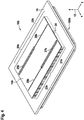
- Figures 1 to 3 show a fluid-based cooling device 10a according to a first embodiment with a first plate 16 and a second plate 14a having two lengthwise continuous (and constant-width) fluid inlet opening regions 26a, 27a.
- Figure 1 shows a top perspective view of the fluid-based cooling device 10a according to the first embodiment.
- Figure 1 also shows a coordinate system 12 having an x-axis corresponding to a first direction, a y-axis corresponding to a second direction and a z-axis corresponding to a third direction.
- the fluid-based cooling device 10a is arranged atop a heat source assembly 100a, e.g. a CPU assembly, which is described in more detail later in conjunction with figures 2 and 3 .
- the fluid-based cooling device 10a further comprises a heat sink structure 18 arranged between the second plate 14a and the first plate 16.
- the first plate 16 is made from a material with high thermal conductivity, e.g. an aluminum alloy, and is in thermal contact with the heat source assembly 100a.
- the first plate 16 conducts heat generated by the heat source assembly 100a to the heat sink structure 18 arranged atop the first plate 16.
- the first plate 16 is described in more detail later in conjunction with figure 15 .
- the heat sink structure 18 has a first heat sink structure portion 20a, a second heat sink structure portion 21a and a single intermediate channel 24 which extends along the direction of the y-axis and is arranged between the first and second heat sink structure portions 20a, 21a.
- the first and second heat sink structure portions 20a, 21a comprise an arrangement of parallel fins extending along the direction of the x-axis each made from a material with a high thermal conductivity, e.g. an aluminum alloy.
- the parallel fins are arranged to form micro-channels between them allowing a cooling fluid (coolant) to flow between them such that heat can be transferred from the first and second heat sink structure portions 20a, 21a to the cooling fluid.
- the second plate 14a has the first fluid inlet opening region 26a and the second fluid inlet opening region 27a formed as elongated openings extending along the y-axis each.
- the first fluid inlet opening region 26a is arranged centered atop of the first heat sink structure portion 20a.
- the second fluid inlet opening region 27a is arranged centered atop of the second heat sink structure portion 21a.
- the first and second fluid inlet opening regions 26a, 27a disperse the cooling fluid flowing into the same from the top of the fluid-based cooling device 10a equally among the micro-channels formed by the parallel fins of the first and second heat sink structure portions 20a, 21a respectively.
- Figure 2 shows a perspective cross section view of the fluid-based cooling device 10a according to the first embodiment and the heat source assembly 100a.
- the fluid-based cooling device 10a and the heat source assembly 100a are cut along a cutting plane extending along the x-axis and z-axis.
- the heat source assembly 100a comprises four heat-generating elements 110a to 113a arranged in a grid-like manner, e.g. four CPU dies comprising multiple CPU each arranged on a printed circuit board (PCB), two of which are shown in figure 2 , and a heat spreader 102.
- the heat spreader 102 is arranged between the heat-generating elements 110a to 113a and the first plate 16.
- the heat spreader 102 is made from a material with high thermal conductivity, e.g. an aluminum alloy, and is in thermal contact with both the four heat-generating elements 110a to 113a and the first plate 16.
- a layer of thermal interface material 104 e.g. thermal grease, is arranged between the first plate 16 and the heat spreader 102.
- the layer of thermal interface material (TIM) 104 improves the thermal contact between the first plate 16 and the heat spreader 102.
- Figure 3 shows a top view of the fluid-based cooling device 10a according to the first embodiment.
- the second plate 14a, the first plate 16, the heat sink structure 18 and the heat spreader 102 are shown transparent in Figure 3 to illustrate the spatial arrangement of the components of the fluid-based cooling device 10a in relation to the components of the heat source assembly 100a. Additionally, arrows P1a to P6a are shown to illustrate the flow of the cooling fluid through the fluid-based cooling device 10a.
- the first heat sink structure portion 20a is arranged atop the first and third heat-generating elements 110a, 112a.
- the second heat sink structure portion 21a is arranged atop the second and fourth heat-generating elements 111a, 113a.
- cold cooling fluid flows through the fluid-based cooling device 10a in (or against) the direction of the y-axis, i.e. from the left (or right) in figure 3 , and indicated by a solid arrow P1a.
- the cold cooling fluid spreads over the second plate 14a as indicated by solid arrows P2a.
- the cold coolant fluid is dispersed equally among the micro-channels formed by the parallel fins of the first and second heat sink structure portions 20a, 21a, respectively. Heat is transferred from the first and second heat sink structure portions 20a, 21a to the cold cooling fluid.
- a part of the now hot i.e.
- heated cooling fluid exits the first and second heat sink structure portions 20a, 21a, and flows into the single intermediate channel 24 as indicated by short dashed arrows P3a.
- the remaining part of the now hot (i.e. heated) cooling fluid exits the first and second heat sink structure portions 20a, 21a and flows into a cavity 54, which encompasses the heat sink structure 18 and the second plate 14a, as indicated by short dashed arrows P4a.
- the hot cooling fluid exits the fluid-based cooling device 10a via the single intermediate channel 24 and the cavity 54 in (or against) the direction of the y-axis, i.e. to the left (or right) in figure 3 , as indicated by long dashed arrows P5a, P6a.
- Figures 4 to 6 show a fluid-based cooling device 10b according to a second embodiment with the second plate 14b having two lengthwise continuous fluid inlet opening regions of varying width.
- Figure 4 shows a top perspective view of the fluid-based cooling device 10b according to the second embodiment.
- the fluid-based cooling device 10b is arranged atop a heat source assembly 100b, e.g. a CPU assembly, which is described in more detail later in conjunction with figures 5 and 6 .
- a heat source assembly 100b e.g. a CPU assembly
- the fluid-based cooling device 10b according to the second embodiment shown in figures 4 to 6 differs from the fluid-based cooling device 10a according to the first embodiment shown in figures 1 to 3 in having a third (constant-width) fluid inlet opening region 28b and a fourth (constant-width) fluid inlet opening region 29b. Further, the fluid-based cooling device 10b according to the second embodiment shown in figures 4 to 6 further differs from the fluid-based cooling device 10a according to the first embodiment shown in figures 1 to 3 in having a third heat sink structure portion 22b and a fourth heat sink structure portion 23b.
- the first (constant-width) fluid inlet opening region 26b and the second (constant-width) fluid inlet opening region 27b have a width greater than the third (constant-width) fluid inlet opening region 28b and the fourth (constant-width) fluid inlet opening region 29b.
- the first fluid inlet opening region 26b and the third fluid inlet opening region 28b are connected with each other forming a first of the two lengthwise continuous fluid inlet opening regions of varying width.
- the second fluid inlet opening region 27b and the fourth fluid inlet opening region 29b are connected with each other forming a second of the two lengthwise continuous fluid inlet opening regions of varying width.
- the first fluid inlet opening region 26b is arranged diagonally opposed to the second fluid inlet opening region 27b.
- the third fluid inlet opening region 28b is arranged diagonally opposed to the forth fluid inlet opening region 29b.
- Figure 5 shows a perspective cross section view of the fluid-based cooling device 10b according to the second embodiment and the heat source assembly 100b.
- the fluid-based cooling device 10b and the heat source assembly 100b are cut along a cutting plane extending along the x-axis and z-axis.
- the heat source assembly 100b comprises two heat-generating elements 110b and 113b, e.g. two CPU dies comprising multiple CPU each, and two non-heat-generating elements 114b and 115b, e.g. two non-functional semiconductor dies used as a purely structural element supporting the heat spreader 102.
- Figure 6 shows a top view of the fluid-based cooling device 10b according to the second embodiment.
- the second plate 14b, the first plate 16, the heat sink structure 18 and the heat spreader 102 are shown transparent in Figure 6 to illustrate the spatial arrangement of the components of the fluid-based cooling device 10b in relation to the components of the heat source assembly 100b. Additionally, arrows P1b to P7b are shown to illustrate the flow of the cooling fluid through the fluid-based cooling device 10b.
- the first fluid inlet opening region 26b is arranged atop the first heat sink structure portion 20b.
- the second fluid inlet opening region 27b is arranged atop the second heat sink structure portion 21b.
- the third fluid inlet opening region 28b is arranged atop the third heat sink structure portion 22b.
- the fourth fluid inlet opening region 29b is arranged atop the fourth heat sink structure portion 23b.
- the first and second heat sink structure portions 20b, 23b are arranged atop the two heat-generating elements 110b, 113b.
- the third and fourth heat sink structure portions 22b, 23b are arranged atop the two non-heat-generating elements 114b, 115b.
- the cold cooling fluid flows through the fluid-based cooling device 10b from the direction of the y-axis, i.e. from the left in figure 6 , and indicated by a solid arrow P1b.
- the cold cooling fluid spreads over the second plate 14b as indicated by solid arrows P2b, P3b. Since the width of the first fluid inlet opening region 26b and the second fluid inlet opening region 27b is greater than the width of the third fluid inlet opening region 28b and the fourth fluid inlet opening region 29b, more of the cold cooling fluid passes through the first fluid inlet opening region 26b and the second fluid inlet opening region 27b than through the third fluid inlet opening region 28b and the fourth fluid inlet opening region 29b.
- the hot cooling fluid exits from the fluid-based cooling device 10b via the first intermediate channel 24 and the cavity 54 in the direction of the y-axis, i.e. to the left (or right) in figure 6 , as indicated by long dashed arrows P6b, P7b.
- Figures 7 and 8 show a fluid-based cooling device 10c according to a third embodiment with a second plate 14c having four (constant-width) fluid inlet opening regions 26c, 27c, 28c, 29c each having the same width.
- the fluid-based cooling device 10c is arranged atop a heat source assembly 100c identical to the heat source assembly 100a shown in figure 1 .
- the fluid-based cooling device 10c according to the third embodiment shown in figures 7 and 8 differs from the fluid-based cooling device 10a according to the first embodiment shown in figures 1 to 3 in having the third (constant-width) fluid inlet opening region 28c and the fourth (constant-width) fluid inlet opening region 29c, in having the third heat sink structure portion 22c and the fourth heat sink structure portion 23c and in having a second intermediate channel 25.
- the heat sink structure portions 20c, 21c, 22c, 23c are spatially separated from each other forming the first and second intermediate channels 24, 25 between them.
- the second intermediate channel 25 is extending in the direction of the x-axis, i.e. perpendicular to the first intermediate channel 24.
- Figure 8 shows a top view of the fluid-based cooling device 10c according to the third embodiment.
- the second plate 14c, the first plate 16, the heat sink structure 18 and the heat spreader 102 are shown transparent in Figure 8 to illustrate the spatial arrangement of the components of the fluid-based cooling device 10c in relation to the components of the heat source assembly 100c. Additionally, arrows P1c to P7c are shown to illustrate the flow of the cooling fluid through the fluid-based cooling device 10c.
- the first to fourth fluid inlet opening regions 26c, 27c, 28c, 29c are arranged atop the first to fourth heat sink structure portions 20c, 21c, 22c, 23c each.
- the first to fourth heat sink structure portions 20c, 21c, 22c, 23c are arranged atop the first to fourth heat-generating elements 110c, 111c, 112c, 113c each.
- the cold cooling fluid flows through the fluid-based cooling device 10c from the direction of the y-axis, i.e. from the left in figure 8 , and indicated by a solid arrow P1c.
- the cold cooling fluid spreads over the second plate 14c as indicated by solid arrows P2c.
- the cold coolant fluid is dispersed equally among the micro-channels formed by the parallel fins of the first to fourth heat sink structure portions 20c, 21c, 22c, 23c, respectively. Heat is transferred from the heat sink structure portions 20c, 21c, 22c, 23c to the cold cooling fluid.
- a part of the now hot i.e.
- heated cooling fluid exits the heat sink structure portions 20c, 21c, 22c, 23c into the first intermediate channel 24 as indicated by short dashed arrows P3c.
- Part of the hot cooling fluid can exit the first intermediate channel 24 into the second intermediate channel 25 as indicated by long dashed arrows P7c.
- the hot cooling fluid exit the second intermediate channel 25 into the cavity 54.
- the remaining A part of the now hot (i.e. heated) cooling fluid exits from the heat sink structure portions 20c, 21c, 22c, 23c into the cavity 54 as indicated by short dashed arrows P4c.
- the hot cooling fluid exits the fluid-based cooling device 10c via the first intermediate channel 24 and the cavity 54 in the direction of the y-axis, i.e. to the left in figure 8 , as indicated by long dashed arrows P6c.
- Figures 9 and 10 show a fluid-based cooling device 10d according to a fourth embodiment with a second plate 14d having four distinct (constant-width) fluid inlet opening regions 26d, 27d, 28d, 29d with two of the four fluid inlet opening regions 26d, 27d having a different width than the remaining two fluid inlet opening regions 28d, 29d.
- the fluid-based cooling device 10d is arranged atop a heat source assembly 100d identical to the heat source assembly 100b shown in figure 4 .
- the fluid-based cooling device 10d according to the fourth embodiment shown in figure 9 differs from the fluid-based cooling device 10c according to the third embodiment shown in figures 7 and 8 in having a first and a second fluid inlet opening region 26d, 27d having a width greater than a width of a third and a fourth fluid inlet opening region 28d, 29d.
- Figure 10 shows a top view of the fluid-based cooling device 10d according to the fourth embodiment.
- the second plate 14d, the first plate 16, the heat sink structure 18 and the heat spreader 102 are shown transparent in Figure 10 to illustrate the spatial arrangement of the components of the fluid-based cooling device 10d in relation to the components of the heat source assembly 100d. Additionally, arrows P1d to P7d are shown to illustrate the flow of the cooling fluid through the fluid-based cooling device 10d.
- the first fluid inlet opening region 26d is arranged atop the first heat sink structure portion 20d.
- the second fluid inlet opening region 27d is arranged atop the second heat sink structure portion 21d.
- the third fluid inlet opening region 28d is arranged atop the third heat sink structure portion 22d.
- the fourth fluid inlet opening region 29d is arranged atop the second heat sink structure portion 23d.
- the first and second heat sink structure portions 26d, 27d are arranged atop the two heat generating elements 110d, 113d.
- the third and fourth heat sink structure portions 22d, 23d are arranged atop the two non-heat-generating elements 114d, 115d.
- the cold cooling fluid flows through the fluid-based cooling device 10d from the direction of the y-axis, i.e. from the left in figure 10 , and indicated by a solid arrow P1d.
- the cold cooling fluid spreads over the second plate 14d as indicated by solid arrows P2d, P3d. Since the width of the first fluid inlet opening region 26d and the second fluid inlet opening region 27d is greater than the width of the third fluid inlet opening region 28d and the fourth fluid inlet opening region 29d, more of the cold cooling fluid passes through the first fluid inlet opening region 26d and the second fluid inlet opening region 27d than through the third fluid inlet opening region 28d and the fourth fluid inlet opening region 29d.
- heated cooling fluid exits the heat sink structure portions 20d, 21d, 22d, 23d into the cavity 54 as indicated by short dashed arrows P5d.
- the hot cooling fluid exits the fluid-based cooling device 10d via the first intermediate channel 24 and the cavity 54 in the direction of the y-axis, i.e. to the left in figure 6 , as indicated by long dashed arrows P6d, P7d.
- Figure 11a shows a top view of a fluid-based cooling device 10e according to a fifth embodiment with the second plate 14e having two coolant evacuation openings 34e, 35e.
- the fluid-based cooling device 10e according to the fifth embodiment shown in figure 11a differs from the fluid-based cooling device 10a according to the first embodiment shown in figures 1 to 3 in having the two coolant evacuation openings 34e, 35e through which hot coolant fluid can exit the first and second heat sink structure portions 20e, 21e in the direction of the z-axis into the cavity 54 of the third plate 50e shown in figure 12 .
- Figure 11b shows a top view of the fluid-based cooling device 10f according to a sixth embodiment with the second plate 14f having two coolant evacuation openings 34f, 35f.
- the fluid-based cooling device 10f according to the sixth embodiment shown in figure 11b differs from the fluid-based cooling device 10b according to the second embodiment shown in figures 4 to 6 in having the two coolant evacuation openings 34f, 35f through which hot coolant fluid can exit the first to fourth heat sink structure portions 20f, 21f, 22f, 23f in the direction of the z-axis into the cavity 54 of the third plate 50e shown in figure 12 .
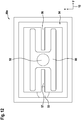
- Figure 12 shows a bottom view of a third plate 50e of the fluid-based cooling device 10e, 10f according to the fifth and sixth embodiment.
- the third plate 50e comprises a cooling fluid inlet opening region 52, a cooling fluid outlet opening 53, the cavity 54 and a cooling fluid input channel 60.
- the cavity 54 comprises a first and a second cooling fluid output channel 56, 57 for transporting the cooling fluid from the first and second coolant evacuation openings 34e, 35e, 34f, 35f of the second plate 14e, 14f shown in figures 11a and 11b to the cooling fluid outlet opening 53.
- the cooling fluid input channel 60 transports the cooling fluid from the cooling fluid inlet opening region 52 to the fluid inlet opening regions 26e, 27e, 26f, 27f, 28f, 29f of the second plate 14e, 14f shown in figures 11a and 11b .
- Figure 13 shows a top view of the fluid-based cooling device 10g according to a seventh embodiment with the second plate 14g having four coolant evacuation openings 34g, 35g, 36g, 37g.
- the fluid-based cooling device 10g according to the seventh embodiment shown in figure 13 differs from the fluid-based cooling device 10c according to the third embodiment shown in figures 7 and 8 in having the four coolant evacuation openings 34g, 35g, 36g, 37g through which hot coolant fluid can exit the first to fourth heat sink structure portions 20g, 21g, 22g, 23g in the direction of the z-axis into the cavity 54 of the third plate 50g shown in figure 14 .
- Figure 14 shows a bottom view of a third plate 50g of the fluid-based cooling device 10g according to the seventh embodiment.
- the third plate 50g according to the seventh embodiment shown in figure 14 differs from the third plate 50e according to the fifth and sixth embodiment shown in figure 14a, 14b and 15 in having a third and a fourth cooling fluid output channel 58, 59 for transporting the cooling fluid from the third and fourth coolant evacuation openings 36g, 37g of the second plate 14g shown in figure 13 to the cooling fluid outlet opening 53.
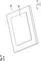
- Figure 15 shows a bottom perspective view of the first plate 16 of the fluid-based cooling device 10 according to the first to seventh embodiment.
- the first plate 16 has four contact surfaces 62, 63, 64, 65 protruding downwards, i.e. in opposite direction of the z-axis, from the first plate 16.
- the four contact surfaces 62, 63, 64, 65 are spatially separated such that a first and a second intermediate channels 66, 67 for receiving a thermal interface material (TIM) are formed between them.
- the first and second intermediate channels 66, 67 for receiving the TIM extend in the direction of the y-axis and the x-axis, respectively.
- the four contact surfaces 62, 63, 64, 65 are in mechanical and thermal contact with the heat spreader 102 of the heat source assembly 100.
- Figure 16 shows a top perspective view of a fluid-based cooling device 10x according to the prior art.
- the fluid-based cooling device 10x comprises a first plate 16x, a second plate 14x and a heat sink structure 18x arranged between the second plate 14x and the first plate 16x.
- the heat sink structure 18x comprises an arrangement of parallel fins machined into the first plate 16x extending along the direction of the x-axis.
- the parallel fins are arranged to form micro-channels between them allowing a cooling fluid to flow between them such that heat can be transferred from the first plate 16x to the cooling fluid.
- the second plate 14x has a fluid inlet opening 26x as an elongated opening extending along the x-axis.
- the fluid inlet opening 26x is arranged centered atop the heat sink structure 18x to disperse the cooling fluid flowing into the same from the top of the fluid-based cooling device 10x (indicated by an arrow P1x) equally among the micro-channels.
- Heat is transferred from the heat sink structure 18x to the cooling fluid.
- the now hot (i.e. heated) cooling fluid exits the heat sink structure portion 18x along and opposite to the direction of the x-axis as indicated by arrows P2x.
- the hot cooling fluid exits the fluid-based cooling device 10x in the direction of the x-axis, i.e. to the left in figure 16 , as indicated by an arrow P3x.
- Figure 17 shows a bottom perspective view of the first plate 16x of the fluid-based cooling device 10x according to the prior art.
- the first plate 16x has a contact surface 62x protruding downwards, i.e. in the opposite direction of the z-axis, from the first plate 16x.
Landscapes
- Engineering & Computer Science (AREA)
- Physics & Mathematics (AREA)
- Microelectronics & Electronic Packaging (AREA)
- Thermal Sciences (AREA)
- Mechanical Engineering (AREA)
- General Engineering & Computer Science (AREA)
- Condensed Matter Physics & Semiconductors (AREA)
- General Physics & Mathematics (AREA)
- Computer Hardware Design (AREA)
- Power Engineering (AREA)
- Materials Engineering (AREA)
- Chemical & Material Sciences (AREA)
- Cooling Or The Like Of Semiconductors Or Solid State Devices (AREA)
- Cooling Or The Like Of Electrical Apparatus (AREA)
Abstract
Description
- The invention relates to a fluid-based cooling device for cooling at least two distinct first heat-generating elements of a heat source assembly. The heat source assembly is in thermal contact with the fluid-based cooling device. The fluid-based cooling device comprises a first plate, a heat sink structure and a second plate. The first plate is configured for thermally contacting the heat source assembly. The heat sink structure is arranged on the first plate. The second plate is configured for directing a flow of a cooling fluid to the heat sink structure. The second plate is arranged on the heat sink structure.
- A state-of-the-art fluid heat exchanger for cooling an electronic device comprises a first plate in thermal contact with a heat generating element, a second plate having a fluid inlet opening and a heat sink structure comprising a plurality of fins arranged between the first and second plates. Typically, the fluid inlet opening of the second plate is arranged centered (or a little off-center) atop the heat sink structure to disperse a cooling fluid over the heat sink structure. The heat sink structure comprises an arrangement of parallel fins machined into the first plate. The parallel fins are arranged to form micro-channels between them allowing the cooling fluid to flow between them such that heat can be transferred from the first plate to the cooling fluid. Such a fluid-based cooling device is disclosed in
US 8,746,330 B2 andUS 2017/0196116 A1 . -
US 2008/0264604 A1 discloses a cooling apparatus for removing heat from an electronic device. The cooling apparatus comprises a manifold structure having a plurality of coolant inlet and outlet passageways interleaved in the manifold structure. The manifold structure further includes coolant inlet and outlet plenums, with cooling fluid passing through the inlet passageways from the inlet plenum in a first direction and cooling fluid passing through the outlet passageways to the outlet plenum in a second direction. The first and second directions are perpendicular to a surface to be cooled. -
WO 2004/042302 A2 discloses a fluid cooled channeled heat exchanger device comprising two flat coupled plates and a plurality of fins coupled to the two plates. One of the plates comprises a plurality of condenser channels configured to receive, to condense and to cool a cooling fluid in a heated state. -
GB 2 402 465 A - Known fluid-based cooling devices fail to optimally cool a heat source assembly, e.g. a CPU or GPU assembly, comprising more than one distinct heat-generating elements, e.g. two or more CPU or GPU dies, when the distinct heat-generating elements are spatially separated from each other.
- It is an object of the present invention to provide a fluid-based cooling device for cooling at least two distinct first heat-generating elements of a heat source assembly allowing for an optimal cooling of at least two spatially separated first heat-generating elements.
- This object is solved by a fluid-based cooling device having the features of claim 1. Advantageous developments of the invention are specified in the dependent claims.
- According to an embodiment, a fluid-based cooling device for cooling at least two distinct first heat-generating elements of a heat source assembly is provided. The heat source assembly is in thermal contact with the fluid-based cooling device. The fluid-based cooling device comprises a first plate, a heat sink structure and a second plate.
- The first plate is configured for thermally contacting the heat source assembly. The heat sink structure is arranged on or in the first plate. The second plate is configured for directing a flow of a cooling fluid to the heat sink structure. The second plate is arranged on the heat sink structure. The heat sink structure comprises at least two heat sink structure portions each corresponding to an associated one of the at least two distinct first heat-generating elements. The second plate comprises at least two fluid inlet opening regions, wherein each of the fluid inlet opening regions is associated with a corresponding heat sink structure portion of the at least two heat sink structure portions.
- Areas of the heat source assembly where the at least two first heat-generating elements are arranged constitute areas of high heat flux, i.e. they heat up more quickly than the remaining areas of the heat source assembly. Since the heat source assembly is in thermal contact with the first plate, the first plate will heat up more quickly in areas associated with the at least two first heat-generating elements. Each of the at least two heat sink structure portions is associated with at least one of the at least two distinct first heat-generating elements, e.g. arranged on the first plate atop the at least one heat-generating element. For optimally cooling the first plate and thereby cooling the heat source assembly, a cooling fluid (coolant) is dispersed over the heat sink structure through the at least two fluid inlet opening regions. Each of the at least two fluid inlet opening regions is associated with a corresponding one of the at least two heat sink structure portions, so that the cooling fluid can selectively be provided for each of the at least two heat sink structure portions. Heat is transferred from each of the at least two heat sink structure portions to the cooling fluid heating the same up, thereby allowing to divert the heat away specifically from the areas of the heat source assembly where the at least two first heat-generating elements are arranged.
- The present invention thus allows for an optimal cooling of at least two spatially separated first heat-generating elements of a heat source assembly such as a multi-die CPU or GPU. By means of the fluid-based cooling device of the present invention, it is possible to optimize the flow of the cooling fluid through the fluid-based cooling device, thereby achieving an optimal cooling performance.
- Preferably, the heat sink structure comprises a plurality of fins extending in parallel in a first direction. The fluid inlet opening regions longitudinally extend in a second direction perpendicular to the first direction. This allows for the cooling fluid to be evenly dispersed among the heat sink structure allowing for a uniform cooling of the first plate and thereby the heat source assembly.
- Preferably, the fluid-based cooling device (including the first plate) has a rectangular shape having a long side and a short side. For example, the long side of the fluid-based cooling device (or the first plate) is parallel to the first direction (i.e. parallel to the fins), while the short side of the fluid-based cooling device (or the first plate) is parallel to the second direction (i.e. perpendicular to the fins). In this case, the long side of the heat source assembly having a rectangular shape is parallel to the first direction, while the short side of the heat source assembly having the rectangular shape is parallel to the second direction. Further, the short side of the fluid-based cooling device (or the first plate) may be parallel to the first direction (i.e. parallel to the fins), while the long side of the fluid-based cooling device (or the first plate) may be parallel to the second direction (i.e. perpendicular to the fins). In this case, the short side of the heat source assembly having a rectangular shape may be parallel to the first direction, while the long side of the heat source assembly having the rectangular shape may be parallel to the second direction.
- If the heat sink structure is, for example, a high-density structure not comprising fins, the first direction may be defined by the short side of the fluid-based cooling device (or the first plate) instead of the (longitudinal) extension of the fins, while the second direction may be defined by the long side of the fluid-based cooling device (or the first plate). Further, in this case, the first direction may also be defined by the long side of the fluid-based cooling device (or the first plate) instead of the (longitudinal) extension of the fins, while the second direction may also be defined by the short side of the fluid-based cooling device (or the first plate). In other words, the configuration of the fluid-based cooling device including the fluid inlet opening regions can be defined with respect to the short or long side of the fluid-based cooling device, i.e. the configuration can be rotated by 90°.
- Preferably, the fluid inlet opening regions have at least a first width adapted to one or more of the at least two first heat-generating elements. This allows for the cooling fluid to be spread in different amounts over the at least two heat sink structure portions allowing different amounts of cooling fluid for different parts of the heat sink structure and thereby the first plate and the heat source assembly.
- Preferably, the fluid inlet opening regions have a second width provided for one or more of second heat-generating elements or non-heat-generating elements of the heat source assembly.
- Preferably, the first width is larger than the second width.
- The non-heat-generating elements, e.g. structural elements of the heat source assembly, do not generate heat themselves. However, due to the presence of the first heat-generating elements, the non-heat-generating elements may heat up during use and also need cooling. For example, the second heat-generating elements are CPU dies which are not disabled, but are intentionally designed in such a way that they generate less heat than the main CPU dies.
- The provision of the fluid inlet opening regions with the relatively small second width allows for the cooling fluid to be spread in relatively small amounts to parts of the heat sink structure (i.e. those corresponding to the second heat-generating elements or non-heat-generating elements) which during use would not heat up as much as other parts of the heat sink structure (i.e. those corresponding to the first heat-generating elements).
- For example, a first fluid inlet opening region of the fluid inlet opening regions having the first width and a second fluid inlet opening region of the fluid inlet opening regions having the second width are spatially separated or connected with each other.
- It is advantageous when the fluid-based cooling device is configured for cooling four distinct first heat-generating elements of the heat source assembly and when the second plate comprises four fluid inlet opening regions corresponding to the four distinct first heat-generating elements.
- Preferably, the fluid-based cooling device is configured for cooling a first pair of diagonally arranged first heat-generating elements and a second pair of diagonally arranged second heat-generating elements or non-heat-generating elements. The second plate comprises four fluid inlet opening regions. Two of the four fluid inlet opening regions corresponding to the first heat-generating elements of the first pair have a width which is larger than the width of the other two of the four fluid inlet opening regions corresponding to the second heat-generating elements or non-heat-generating elements of the second pair. Thus, a larger amount of cooling fluid can be provided through the two of the four fluid inlet opening regions corresponding to the first heat-generating elements than through the other two of the four fluid inlet opening regions corresponding to the second heat-generating elements or non-heat-generating elements. Accordingly, the cooling of the heat source assembly can further be optimized.
- It is advantageous when the heat sink structure comprises at least two spatially separated heat sink structure portions forming at least a first intermediate channel and/or a second intermediate channel for diverting the cooling fluid after having been heated therefrom.
- For example, the heat sink structure comprises a plurality of fins extending in parallel in a first direction, and the first intermediate channel extends in a second direction perpendicular to the first direction.
- For example, the heat sink structure comprises a plurality of fins extending in parallel in a first direction, and the second intermediate channel extends in the first direction.
- Alternatively, a first and a second of the at least two heat sink structure portions are connected with each other without forming an intermediate channel therebetween.
- Preferably, the fluid-based cooling device comprises a third plate arranged above the first and the second plate. The first, the second and/or the third plate comprises at least one cooling fluid input or output channel. The third plate is utilized to provide a fluid chamber for the cooling fluid to be directed via the cooling fluid input or output channel to the heat sink structure and further optimize the flow of the cooling fluid through the fluid-based cooling device. Thereby, further optimizing the cooling of the heat source assembly can be achieved.
- It is advantageous when the first plate comprises at least two contact surfaces protruding from a surface of the first plate facing away from the heat sink structure for thermally contacting a heat spreader of the heat source assembly and when the contact surfaces each correspond to the at least two distinct first heat-generating elements.
- Preferably, the contact surfaces of the first plate are spatially separated, thereby forming at least one intermediate channel for receiving a thermal interface material (TIM).
- Thermal interface material, e.g. thermal grease, is used to increase the thermal contact between the fluid-based cooling device and the heat source assembly. However, if the contact surfaces between the fluid-based cooling device and the heat source assembly are too large, it becomes difficult to evenly spread the thermal interface material evenly over the contact surfaces. Thus, the intermediate channel provides a space for excess thermal interface material to spread to.
- For example, the heat sink structure comprises a plurality of fins and/or pins and/or micro-channels (cavities) defined by the fins. The heat sink structure may be any high-density structure, i.e. structure having a plurality of protrusions characterized by a large (maximized) surface area. Further, the protrusions (e.g. fins) may have different shapes such as longitudinally extending parallel or angled fins.
- In particular, the heat sink structure may comprise a fin or pin structure or other high density cooling structure, e.g. structure comprising fins and pins, having different pin forms, such as elliptic, dropform, NACA, circular or square.
- The heat source assembly may be a CPU or GPU assembly. The first heat-generating elements and/or the second heat-generating elements are, for example, CPU or GPU dies containing multiple CPU or GPU, respectively, or single, preferably high performance CPU or GPU. The non-heat-generating elements may be non-functional or disabled semiconductor dies or structural elements, e.g. supporting the heat spreader. Preferably, the second heat-generating elements are configured to generate less heat than the first heat-generating elements.
- Preferably, the first plate and/or the heat sink structure are made from a material with a high thermal conductivity, e.g. copper, aluminum or an alloy thereof.
- For example, the first, second and/or third plate are manufactured by means of injection molding or milling. Preferably, the first, second and/or third plate are substantially plate-shaped elements. The second plate is a fluid directing element and can also be referred to as "impingement plate". The second plate may also be of a shape other than plate-shaped.
- Alternatively, the first and/or second intermediate channel may be formed in the second or second and third plate. In this case, the two heat sink structure portions of the heat sink structure may be connected with each other without forming an intermediate channel therebetween. By means of the first and/or second intermediate channel formed in the second or second and third plate, the cooling fluid after having been heated when flowing through the heat sink structure can be diverted therefrom. In other words, the heated cooling fluid can also exit the fluid-based cooling device via the intermediate channels formed in the second or second and third plate above the (continuous) heat sink structure.
- In the case that the first and/or second intermediate channel are formed in the second or second and third plate, the two fluid inlet opening regions of the second plate may be connected with each other. For example, the fluid inlet opening regions may be of a straight or curved shape and together may form the shape of an "X" (e.g. X-shape or similar shape).
- Preferably, in a cross section view, the fluid-based cooling device comprises the two fluid inlet opening regions of the second plate and one intermediate channel (e.g. one of the first and/or second intermediate channel formed in the second or second and third plate or one of the first and/or second intermediate channel formed by the two spatially separated heat sink structure portions) arranged preferably centrally between the two fluid inlet opening regions.
- Preferably, the heat sink structure and the first plate are integrally formed, i.e. the heat sink structure may be part of the first plate, or the heat sink structure and the first plate may be two separate elements of the fluid-based cooling device. For example, the heat sink structure may be arranged in the first plate (e.g. on a recessed inner surface of the first plate), or the heat sink structure may be arranged on the first plate (e.g. on an upper surface of the first plate).
- Further features and advantages of the invention result from the following description which explains the invention in more detail on the basis of embodiments in connection with the enclosed schematic figures:
- Figure 1
- shows a top perspective view of a fluid-based cooling device according to a first embodiment with a first plate and a second plate, the second plate having two lengthwise continuous fluid inlet opening regions;
- Figure 2
- shows a perspective cross section view of the fluid-based cooling device according to the first embodiment;
- Figure 3
- shows a top view of the fluid-based cooling device according to the first embodiment;
- Figure 4
- shows a top perspective view of the fluid-based cooling device according to a second embodiment with the second plate having two lengthwise continuous fluid inlet opening regions of varying width;
- Figure 5
- shows a perspective cross section view of the fluid-based cooling device according to the second embodiment;
- Figure 6
- shows a top view of the fluid-based cooling device according to the second embodiment;
- Figure 7
- shows a top perspective view of the fluid-based cooling device according to a third embodiment with the second plate having four lengthwise spatially separated fluid inlet opening regions;
- Figure 8
- shows a top view of the fluid-based cooling device according to the third embodiment;
- Figure 9
- shows a top perspective view of the fluid-based cooling device according to a fourth embodiment with the second plate having four lengthwise spatially separated fluid inlet opening regions with two of the four fluid inlet opening regions having a different width than the remaining two fluid inlet opening regions;
- Figure 10
- shows a top view of the fluid-based cooling device according to the fourth embodiment;
- Figure 11a
- shows a top view of the fluid-based cooling device according to a fifth embodiment with the second plate having two coolant evacuation openings;
- Figure 11b
- shows a top view of the fluid-based cooling device according to a sixth embodiment with the second plate having the two coolant evacuation openings;
- Figure 12
- shows a bottom view of a third plate of the fluid-based cooling device according to the fifth and sixth embodiment;
- Figure 13
- shows a top view of the fluid-based cooling device according to a seventh embodiment with four coolant evacuation openings;
- Figure 14
- shows a bottom view of the third plate of the fluid-based cooling device according to a seventh embodiment;
- Figure 15
- shows a bottom perspective view of the first plate of the fluid-based cooling device according to the first to seventh embodiment;
- Figure 16
- shows a top perspective view of a fluid-based cooling device according to the prior art; and
- Figure 17
- shows a bottom perspective view of a first plate of the fluid-based cooling device according to the prior art.
-
Figures 1 to 3 show a fluid-basedcooling device 10a according to a first embodiment with afirst plate 16 and asecond plate 14a having two lengthwise continuous (and constant-width) fluidinlet opening regions -
Figure 1 shows a top perspective view of the fluid-basedcooling device 10a according to the first embodiment.Figure 1 also shows a coordinatesystem 12 having an x-axis corresponding to a first direction, a y-axis corresponding to a second direction and a z-axis corresponding to a third direction. The fluid-basedcooling device 10a is arranged atop aheat source assembly 100a, e.g. a CPU assembly, which is described in more detail later in conjunction withfigures 2 and3 . The fluid-basedcooling device 10a further comprises aheat sink structure 18 arranged between thesecond plate 14a and thefirst plate 16. - The
first plate 16 is made from a material with high thermal conductivity, e.g. an aluminum alloy, and is in thermal contact with theheat source assembly 100a. Thefirst plate 16 conducts heat generated by theheat source assembly 100a to theheat sink structure 18 arranged atop thefirst plate 16. Thefirst plate 16 is described in more detail later in conjunction withfigure 15 . - The
heat sink structure 18 has a first heatsink structure portion 20a, a second heatsink structure portion 21a and a singleintermediate channel 24 which extends along the direction of the y-axis and is arranged between the first and second heatsink structure portions sink structure portions sink structure portions - The
second plate 14a has the first fluidinlet opening region 26a and the second fluidinlet opening region 27a formed as elongated openings extending along the y-axis each. The first fluidinlet opening region 26a is arranged centered atop of the first heatsink structure portion 20a. The second fluidinlet opening region 27a is arranged centered atop of the second heatsink structure portion 21a. The first and second fluidinlet opening regions cooling device 10a equally among the micro-channels formed by the parallel fins of the first and second heatsink structure portions -
Figure 2 shows a perspective cross section view of the fluid-basedcooling device 10a according to the first embodiment and theheat source assembly 100a. The fluid-basedcooling device 10a and theheat source assembly 100a are cut along a cutting plane extending along the x-axis and z-axis. - According to the first embodiment, the
heat source assembly 100a comprises four heat-generatingelements 110a to 113a arranged in a grid-like manner, e.g. four CPU dies comprising multiple CPU each arranged on a printed circuit board (PCB), two of which are shown infigure 2 , and aheat spreader 102. Theheat spreader 102 is arranged between the heat-generatingelements 110a to 113a and thefirst plate 16. Theheat spreader 102 is made from a material with high thermal conductivity, e.g. an aluminum alloy, and is in thermal contact with both the four heat-generatingelements 110a to 113a and thefirst plate 16. A layer ofthermal interface material 104, e.g. thermal grease, is arranged between thefirst plate 16 and theheat spreader 102. The layer of thermal interface material (TIM) 104 improves the thermal contact between thefirst plate 16 and theheat spreader 102. -
Figure 3 shows a top view of the fluid-basedcooling device 10a according to the first embodiment. Thesecond plate 14a, thefirst plate 16, theheat sink structure 18 and theheat spreader 102 are shown transparent inFigure 3 to illustrate the spatial arrangement of the components of the fluid-basedcooling device 10a in relation to the components of theheat source assembly 100a. Additionally, arrows P1a to P6a are shown to illustrate the flow of the cooling fluid through the fluid-basedcooling device 10a. - As can be seen in
figure 3 , the first heatsink structure portion 20a is arranged atop the first and third heat-generatingelements sink structure portion 21a is arranged atop the second and fourth heat-generatingelements - In operation, cold cooling fluid flows through the fluid-based
cooling device 10a in (or against) the direction of the y-axis, i.e. from the left (or right) infigure 3 , and indicated by a solid arrow P1a. The cold cooling fluid spreads over thesecond plate 14a as indicated by solid arrows P2a. After passing through the first and second fluidinlet opening regions sink structure portions sink structure portions sink structure portions intermediate channel 24 as indicated by short dashed arrows P3a. The remaining part of the now hot (i.e. heated) cooling fluid exits the first and second heatsink structure portions cavity 54, which encompasses theheat sink structure 18 and thesecond plate 14a, as indicated by short dashed arrows P4a. The hot cooling fluid exits the fluid-basedcooling device 10a via the singleintermediate channel 24 and thecavity 54 in (or against) the direction of the y-axis, i.e. to the left (or right) infigure 3 , as indicated by long dashed arrows P5a, P6a. -
Figures 4 to 6 show a fluid-basedcooling device 10b according to a second embodiment with thesecond plate 14b having two lengthwise continuous fluid inlet opening regions of varying width. -
Figure 4 shows a top perspective view of the fluid-basedcooling device 10b according to the second embodiment. The fluid-basedcooling device 10b is arranged atop aheat source assembly 100b, e.g. a CPU assembly, which is described in more detail later in conjunction withfigures 5 and6 . - The fluid-based
cooling device 10b according to the second embodiment shown infigures 4 to 6 differs from the fluid-basedcooling device 10a according to the first embodiment shown infigures 1 to 3 in having a third (constant-width) fluidinlet opening region 28b and a fourth (constant-width) fluidinlet opening region 29b. Further, the fluid-basedcooling device 10b according to the second embodiment shown infigures 4 to 6 further differs from the fluid-basedcooling device 10a according to the first embodiment shown infigures 1 to 3 in having a third heatsink structure portion 22b and a fourth heatsink structure portion 23b. - The first (constant-width) fluid
inlet opening region 26b and the second (constant-width) fluidinlet opening region 27b have a width greater than the third (constant-width) fluidinlet opening region 28b and the fourth (constant-width) fluidinlet opening region 29b. The first fluidinlet opening region 26b and the third fluidinlet opening region 28b are connected with each other forming a first of the two lengthwise continuous fluid inlet opening regions of varying width. The second fluidinlet opening region 27b and the fourth fluidinlet opening region 29b are connected with each other forming a second of the two lengthwise continuous fluid inlet opening regions of varying width. The first fluidinlet opening region 26b is arranged diagonally opposed to the second fluidinlet opening region 27b. The third fluidinlet opening region 28b is arranged diagonally opposed to the forth fluidinlet opening region 29b. -
Figure 5 shows a perspective cross section view of the fluid-basedcooling device 10b according to the second embodiment and theheat source assembly 100b. The fluid-basedcooling device 10b and theheat source assembly 100b are cut along a cutting plane extending along the x-axis and z-axis. - According to the second embodiment, the
heat source assembly 100b comprises two heat-generatingelements elements heat spreader 102. -
Figure 6 shows a top view of the fluid-basedcooling device 10b according to the second embodiment. Thesecond plate 14b, thefirst plate 16, theheat sink structure 18 and theheat spreader 102 are shown transparent inFigure 6 to illustrate the spatial arrangement of the components of the fluid-basedcooling device 10b in relation to the components of theheat source assembly 100b. Additionally, arrows P1b to P7b are shown to illustrate the flow of the cooling fluid through the fluid-basedcooling device 10b. - As can be seen in
figure 6 , the first fluidinlet opening region 26b is arranged atop the first heatsink structure portion 20b. The second fluidinlet opening region 27b is arranged atop the second heatsink structure portion 21b. The third fluidinlet opening region 28b is arranged atop the third heatsink structure portion 22b. The fourth fluidinlet opening region 29b is arranged atop the fourth heatsink structure portion 23b. The first and second heatsink structure portions elements sink structure portions elements - The cold cooling fluid flows through the fluid-based
cooling device 10b from the direction of the y-axis, i.e. from the left infigure 6 , and indicated by a solid arrow P1b. The cold cooling fluid spreads over thesecond plate 14b as indicated by solid arrows P2b, P3b. Since the width of the first fluidinlet opening region 26b and the second fluidinlet opening region 27b is greater than the width of the third fluidinlet opening region 28b and the fourth fluidinlet opening region 29b, more of the cold cooling fluid passes through the first fluidinlet opening region 26b and the second fluidinlet opening region 27b than through the third fluidinlet opening region 28b and the fourth fluidinlet opening region 29b. Thereby, more cold cooling fluid is dispersed over the first and second heatsink structure portions sink structure portions sink structure portions sink structure portions intermediate channel 24 as indicated by short dashed arrows P4b. The remaining part of the now hot (i.e. heated) cooling fluid exits the heatsink structure portions cavity 54 as indicated by short dashed arrows P5b. The hot cooling fluid exits from the fluid-basedcooling device 10b via the firstintermediate channel 24 and thecavity 54 in the direction of the y-axis, i.e. to the left (or right) infigure 6 , as indicated by long dashed arrows P6b, P7b. -
Figures 7 and8 show a fluid-basedcooling device 10c according to a third embodiment with asecond plate 14c having four (constant-width) fluidinlet opening regions cooling device 10c is arranged atop aheat source assembly 100c identical to theheat source assembly 100a shown infigure 1 . - The fluid-based
cooling device 10c according to the third embodiment shown infigures 7 and8 differs from the fluid-basedcooling device 10a according to the first embodiment shown infigures 1 to 3 in having the third (constant-width) fluidinlet opening region 28c and the fourth (constant-width) fluidinlet opening region 29c, in having the third heatsink structure portion 22c and the fourth heatsink structure portion 23c and in having a secondintermediate channel 25. - The heat
sink structure portions intermediate channels intermediate channel 25 is extending in the direction of the x-axis, i.e. perpendicular to the firstintermediate channel 24. -
Figure 8 shows a top view of the fluid-basedcooling device 10c according to the third embodiment. Thesecond plate 14c, thefirst plate 16, theheat sink structure 18 and theheat spreader 102 are shown transparent inFigure 8 to illustrate the spatial arrangement of the components of the fluid-basedcooling device 10c in relation to the components of theheat source assembly 100c. Additionally, arrows P1c to P7c are shown to illustrate the flow of the cooling fluid through the fluid-basedcooling device 10c. - As can be seen in
figure 8 , the first to fourth fluidinlet opening regions sink structure portions sink structure portions elements - The cold cooling fluid flows through the fluid-based
cooling device 10c from the direction of the y-axis, i.e. from the left infigure 8 , and indicated by a solid arrow P1c. The cold cooling fluid spreads over thesecond plate 14c as indicated by solid arrows P2c. After passing through the first to fourth fluidinlet opening regions sink structure portions sink structure portions sink structure portions intermediate channel 24 as indicated by short dashed arrows P3c. Part of the hot cooling fluid can exit the firstintermediate channel 24 into the secondintermediate channel 25 as indicated by long dashed arrows P7c. The hot cooling fluid exit the secondintermediate channel 25 into thecavity 54. The remaining A part of the now hot (i.e. heated) cooling fluid exits from the heatsink structure portions cavity 54 as indicated by short dashed arrows P4c. The hot cooling fluid exits the fluid-basedcooling device 10c via the firstintermediate channel 24 and thecavity 54 in the direction of the y-axis, i.e. to the left infigure 8 , as indicated by long dashed arrows P6c. -
Figures 9 and10 show a fluid-basedcooling device 10d according to a fourth embodiment with asecond plate 14d having four distinct (constant-width) fluidinlet opening regions inlet opening regions inlet opening regions cooling device 10d is arranged atop aheat source assembly 100d identical to theheat source assembly 100b shown infigure 4 . - The fluid-based
cooling device 10d according to the fourth embodiment shown infigure 9 differs from the fluid-basedcooling device 10c according to the third embodiment shown infigures 7 and8 in having a first and a second fluidinlet opening region inlet opening region -
Figure 10 shows a top view of the fluid-basedcooling device 10d according to the fourth embodiment. Thesecond plate 14d, thefirst plate 16, theheat sink structure 18 and theheat spreader 102 are shown transparent inFigure 10 to illustrate the spatial arrangement of the components of the fluid-basedcooling device 10d in relation to the components of theheat source assembly 100d. Additionally, arrows P1d to P7d are shown to illustrate the flow of the cooling fluid through the fluid-basedcooling device 10d. - As can be seen in
figure 10 , the first fluidinlet opening region 26d is arranged atop the first heatsink structure portion 20d. The second fluidinlet opening region 27d is arranged atop the second heatsink structure portion 21d. The third fluidinlet opening region 28d is arranged atop the third heatsink structure portion 22d. The fourth fluidinlet opening region 29d is arranged atop the second heatsink structure portion 23d. The first and second heatsink structure portions heat generating elements sink structure portions elements - The cold cooling fluid flows through the fluid-based
cooling device 10d from the direction of the y-axis, i.e. from the left infigure 10 , and indicated by a solid arrow P1d. The cold cooling fluid spreads over thesecond plate 14d as indicated by solid arrows P2d, P3d. Since the width of the first fluidinlet opening region 26d and the second fluidinlet opening region 27d is greater than the width of the third fluidinlet opening region 28d and the fourth fluidinlet opening region 29d, more of the cold cooling fluid passes through the first fluidinlet opening region 26d and the second fluidinlet opening region 27d than through the third fluidinlet opening region 28d and the fourth fluidinlet opening region 29d. Thereby, more cold cooling fluid is dispersed over the first and second heatsink structure portions sink structure portions sink structure portions sink structure portions intermediate channel 24 as indicated by short dashed arrows P5d. Part of the hot cooling fluid can exit the firstintermediate channel 24 into the secondintermediate channel 25 as indicated by long dashed arrows P8d. The hot cooling fluid exit the secondintermediate channel 25 into thecavity 54. The remaining part of the now hot (i.e. heated) cooling fluid exits the heatsink structure portions cavity 54 as indicated by short dashed arrows P5d. The hot cooling fluid exits the fluid-basedcooling device 10d via the firstintermediate channel 24 and thecavity 54 in the direction of the y-axis, i.e. to the left infigure 6 , as indicated by long dashed arrows P6d, P7d. -
Figure 11a shows a top view of a fluid-basedcooling device 10e according to a fifth embodiment with thesecond plate 14e having twocoolant evacuation openings cooling device 10e according to the fifth embodiment shown infigure 11a differs from the fluid-basedcooling device 10a according to the first embodiment shown infigures 1 to 3 in having the twocoolant evacuation openings sink structure portions cavity 54 of thethird plate 50e shown infigure 12 . -
Figure 11b shows a top view of the fluid-basedcooling device 10f according to a sixth embodiment with thesecond plate 14f having twocoolant evacuation openings cooling device 10f according to the sixth embodiment shown infigure 11b differs from the fluid-basedcooling device 10b according to the second embodiment shown infigures 4 to 6 in having the twocoolant evacuation openings sink structure portions cavity 54 of thethird plate 50e shown infigure 12 . -
Figure 12 shows a bottom view of athird plate 50e of the fluid-basedcooling device third plate 50e comprises a cooling fluidinlet opening region 52, a coolingfluid outlet opening 53, thecavity 54 and a coolingfluid input channel 60. - The
cavity 54 comprises a first and a second coolingfluid output channel coolant evacuation openings second plate figures 11a and11b to the coolingfluid outlet opening 53. The coolingfluid input channel 60 transports the cooling fluid from the cooling fluidinlet opening region 52 to the fluidinlet opening regions second plate figures 11a and11b . -
Figure 13 shows a top view of the fluid-basedcooling device 10g according to a seventh embodiment with the second plate 14g having fourcoolant evacuation openings cooling device 10g according to the seventh embodiment shown infigure 13 differs from the fluid-basedcooling device 10c according to the third embodiment shown infigures 7 and8 in having the fourcoolant evacuation openings sink structure portions cavity 54 of thethird plate 50g shown infigure 14 . -
Figure 14 shows a bottom view of athird plate 50g of the fluid-basedcooling device 10g according to the seventh embodiment. Thethird plate 50g according to the seventh embodiment shown infigure 14 differs from thethird plate 50e according to the fifth and sixth embodiment shown infigure 14a, 14b and15 in having a third and a fourth coolingfluid output channel 58, 59 for transporting the cooling fluid from the third and fourthcoolant evacuation openings figure 13 to the coolingfluid outlet opening 53. -
Figure 15 shows a bottom perspective view of thefirst plate 16 of the fluid-based cooling device 10 according to the first to seventh embodiment. Thefirst plate 16 has fourcontact surfaces first plate 16. The fourcontact surfaces intermediate channels intermediate channels contact surfaces heat spreader 102 of the heat source assembly 100. -
Figure 16 shows a top perspective view of a fluid-basedcooling device 10x according to the prior art. The fluid-basedcooling device 10x comprises afirst plate 16x, asecond plate 14x and aheat sink structure 18x arranged between thesecond plate 14x and thefirst plate 16x. Theheat sink structure 18x comprises an arrangement of parallel fins machined into thefirst plate 16x extending along the direction of the x-axis. The parallel fins are arranged to form micro-channels between them allowing a cooling fluid to flow between them such that heat can be transferred from thefirst plate 16x to the cooling fluid. - According to the prior art, the
second plate 14x has a fluid inlet opening 26x as an elongated opening extending along the x-axis. Thefluid inlet opening 26x is arranged centered atop theheat sink structure 18x to disperse the cooling fluid flowing into the same from the top of the fluid-basedcooling device 10x (indicated by an arrow P1x) equally among the micro-channels. Heat is transferred from theheat sink structure 18x to the cooling fluid. The now hot (i.e. heated) cooling fluid exits the heatsink structure portion 18x along and opposite to the direction of the x-axis as indicated by arrows P2x. The hot cooling fluid exits the fluid-basedcooling device 10x in the direction of the x-axis, i.e. to the left infigure 16 , as indicated by an arrow P3x. -
Figure 17 shows a bottom perspective view of thefirst plate 16x of the fluid-basedcooling device 10x according to the prior art. Thefirst plate 16x has acontact surface 62x protruding downwards, i.e. in the opposite direction of the z-axis, from thefirst plate 16x. -
- 10
- Fluid-based cooling device
- 12
- Coordinate system
- 14, 16, 50
- Plate
- 18
- Heat sink structure
- 20, 21, 22, 23
- Heat sink structure portion
- 24, 25, 66, 67
- Intermediate channel
- 26, 27, 28, 29
- Fluid inlet opening region
- 52
- Cooling fluid inlet opening region
- 53
- Cooling fluid outlet opening
- 54
- Cavity
- 56, 57, 58, 59
- Cooling fluid output channel
- 60
- Cooling fluid input channel
- 62, 63, 64, 65
- Contact surface
- 100
- Heat source assembly
- 102
- Heat spreader
- 110, 111, 112, 113
- Heat-generating elements
- 114, 115
- Non-heat generating elements
Claims (15)
- Fluid-based cooling device (10) for cooling at least two distinct first heat-generating elements (110, 111) of a heat source assembly (100), the heat source assembly (100) being in thermal contact with the fluid-based cooling device (10), the fluid-based cooling device (10) comprising:a first plate (16) for thermally contacting the heat source assembly (100);a heat sink structure (18), wherein the heat sink structure (18) is arranged on or in the first plate (16); anda second plate (14) for directing a flow of a cooling fluid to the heat sink structure (18), wherein the second plate (14) is arranged on the heat sink structure (18);characterized in that the heat sink structure (18) comprises at least two heat sink structure portions (20, 21) each corresponding to an associated one of the at least two distinct first heat-generating elements (110, 111), and in that the second plate (14) comprises at least two fluid inlet opening regions (26, 27), wherein each of the fluid inlet opening regions (26, 27) is associated with a corresponding heat sink structure portion (20, 21) of the at least two heat sink structure portions (20, 21).
- The fluid-based cooling device according to claim 1, characterized in that the heat sink structure (18) comprises a plurality of fins extending in parallel in a first direction, and in that the fluid inlet opening regions (26, 27) longitudinally extend in a second direction perpendicular to the first direction.
- The fluid-based cooling device according to claim 1 or 2, characterized in that the fluid inlet opening regions (26, 27) have at least a first width adapted to one or more of the at least two first heat-generating elements (110, 111).
- The fluid-based cooling device according to claim 3, characterized in that the fluid inlet opening regions (28, 29) have a second width provided for one or more of second heat-generating elements or non-heat-generating elements (114, 115) of the heat source assembly (100).
- The fluid-based cooling device according to claim 4, characterized in that the first width is larger than the second width.
- The fluid-based cooling device according to claim 4 or 5, characterized in that a first fluid inlet opening region (26) of the fluid inlet opening regions (26, 27) having the first width and a second fluid inlet opening region (28) of the fluid inlet opening regions (28, 29) having the second width are spatially separated or connected with each other.
- The fluid-based cooling device according to one of the claims 1 to 6, characterized in that the fluid-based cooling device (10) is configured for cooling four distinct first heat-generating elements (110, 111, 112, 113) of the heat source assembly (100), and in that the second plate (14) comprises four fluid inlet opening regions (26, 27, 28, 29) corresponding to the four distinct first heat-generating elements (110, 111, 112, 113).
- The fluid-based cooling device according to one of the claims 1 to 7, characterized in that the fluid-based cooling device (10) is configured for cooling a first pair of diagonally arranged first heat-generating elements (110, 113) and a second pair of diagonally arranged second heat-generating elements or non-heat-generating elements (114, 115), in that the second plate (14) comprises four fluid inlet opening regions (26, 27, 28, 29), and in that two of the four fluid inlet opening regions (26, 27) corresponding to the first heat-generating elements (110, 113) of the first pair have a width which is larger than the width of the other two of the four fluid inlet opening regions (28, 29) corresponding to the second heat-generating elements or non-heat-generating elements (114, 115) of the second pair.
- The fluid-based cooling device according to one of the claims 1 to 8, characterized in that the heat sink structure (18) comprises at least two spatially separated heat sink structure portions (20, 21) forming at least a first intermediate channel (24) and/or a second intermediate channel (25) for diverting the cooling fluid after having been heated therefrom.
- The fluid-based cooling device according to claim 9, characterized in that the heat sink structure (18) comprises a plurality of fins extending in parallel in a first direction, and in that the first intermediate channel (24) extends in a second direction perpendicular to the first direction.
- The fluid-based cooling device according to claim 9, characterized in that the heat sink structure (18) comprises a plurality of fins extending in parallel in a first direction, and in that the second intermediate (25) channel extends in the first direction.
- The fluid-based cooling device according to one of the claims 1 to 11, characterized in that the fluid-based cooling device (10) comprises a third plate (50) arranged above the first and the second plate (16, 14), and in that the first, the second and/or the third plate (16, 14, 50) comprises at least one cooling fluid input or output channel (56, 60).
- The fluid-based cooling device according to one of the claims 1 to 12, characterized in that the first plate (16) comprises at least two contact surfaces (62, 63) protruding from a surface of the first plate (16) facing away from the heat sink structure (18) for thermally contacting a heat spreader (102) of the heat source assembly (100), and in that the contact surfaces (62, 63) each correspond to the at least two distinct first heat-generating elements (110, 111).
- The fluid-based cooling device according to claim 13, characterized in that the contact surfaces (62, 63) of the first plate (16) are spatially separated, thereby forming at least one intermediate channel (66) for receiving a thermal interface material (TIM).
- The fluid-based cooling device according to one of the claims 1 to 14, characterized in that the heat sink structure (18) comprises a plurality of fins and/or pins and/or micro-channels defined by the fins.
Priority Applications (4)
| Application Number | Priority Date | Filing Date | Title |
|---|---|---|---|
| EP18170404.0A EP3564992B1 (en) | 2018-05-02 | 2018-05-02 | Fluid-based cooling device for cooling at least two distinct first heat-generating elements of a heat source assembly |
| PCT/EP2019/060924 WO2019211238A1 (en) | 2018-05-02 | 2019-04-29 | Fluid-based cooling device for cooling at least two distinct first heat-generating elements of a heat source assembly |
| CN201980027370.5A CN112020629B (en) | 2018-05-02 | 2019-04-29 | Fluid-based cooling device for cooling at least two different first heat generating elements of a heat source assembly |
| US17/051,093 US20210247151A1 (en) | 2018-05-02 | 2019-04-29 | Fluid-based cooling device for cooling at least two distinct first heat-generating elements of a heat source assembly |
Applications Claiming Priority (1)
| Application Number | Priority Date | Filing Date | Title |
|---|---|---|---|
| EP18170404.0A EP3564992B1 (en) | 2018-05-02 | 2018-05-02 | Fluid-based cooling device for cooling at least two distinct first heat-generating elements of a heat source assembly |
Publications (2)
| Publication Number | Publication Date |
|---|---|
| EP3564992A1 true EP3564992A1 (en) | 2019-11-06 |
| EP3564992B1 EP3564992B1 (en) | 2021-07-07 |
Family
ID=62110906
Family Applications (1)
| Application Number | Title | Priority Date | Filing Date |
|---|---|---|---|
| EP18170404.0A Active EP3564992B1 (en) | 2018-05-02 | 2018-05-02 | Fluid-based cooling device for cooling at least two distinct first heat-generating elements of a heat source assembly |
Country Status (4)
| Country | Link |
|---|---|
| US (1) | US20210247151A1 (en) |
| EP (1) | EP3564992B1 (en) |
| CN (1) | CN112020629B (en) |
| WO (1) | WO2019211238A1 (en) |
Families Citing this family (2)
| Publication number | Priority date | Publication date | Assignee | Title |
|---|---|---|---|---|
| US11596088B2 (en) * | 2021-01-29 | 2023-02-28 | Toyota Motor Engineering & Manufacturing North America, Inc. | Asymmetric configurable double-sided manifold micro-channel cold plates |
| JP2023140076A (en) * | 2022-03-22 | 2023-10-04 | 三菱重工業株式会社 | Cooling device |
Citations (7)
| Publication number | Priority date | Publication date | Assignee | Title |
|---|---|---|---|---|
| US5973921A (en) * | 1997-11-03 | 1999-10-26 | Lin; Yu-Chen | Fixation structure for the fan of the CPU heat dissipating device |
| US6062301A (en) * | 1998-06-23 | 2000-05-16 | Foxconn Precision Components, Co., Ltd. | Knockdown CPU heat dissipater |
| WO2004042302A2 (en) | 2002-11-01 | 2004-05-21 | Cooligy, Inc. | Channeled flat plate fin heat exchange system, device and method |
| GB2402465A (en) | 2003-05-27 | 2004-12-08 | Edwin Robinson | Split flow heat exchanger |
| US20080264604A1 (en) | 2007-04-24 | 2008-10-30 | International Business Machines Corporation | Cooling appartaus, cooled electronic module and methods of fabrication employing a manifold structure with interleaved coolant inlet and outlet passageways |
| US8746330B2 (en) | 2007-08-09 | 2014-06-10 | Coolit Systems Inc. | Fluid heat exchanger configured to provide a split flow |
| US20170055378A1 (en) * | 2015-08-20 | 2017-02-23 | Toyota Motor Engineering & Manufacturing North America, Inc. | Configurable double-sided modular jet impingement assemblies for electronics cooling |
Family Cites Families (16)
| Publication number | Priority date | Publication date | Assignee | Title |
|---|---|---|---|---|
| TWI281376B (en) * | 2005-02-25 | 2007-05-11 | Foxconn Tech Co Ltd | Cooling device for plural heat generating components |
| CN2819289Y (en) * | 2005-03-29 | 2006-09-20 | 番禺得意精密电子工业有限公司 | Radiator |
| JP5120605B2 (en) * | 2007-05-22 | 2013-01-16 | アイシン・エィ・ダブリュ株式会社 | Semiconductor module and inverter device |
| US9109985B2 (en) * | 2011-09-27 | 2015-08-18 | Toyota Jidosha Kabushiki Kaisha | Malfunction detecting device and malfunction detecting method for cooling device |
| JP5901343B2 (en) * | 2012-02-24 | 2016-04-06 | 三菱電機株式会社 | Cooler and cooling device |
| US9472488B2 (en) * | 2012-04-16 | 2016-10-18 | Fuji Electric Co., Ltd. | Semiconductor device and cooler thereof |
| WO2014069174A1 (en) * | 2012-10-29 | 2014-05-08 | 富士電機株式会社 | Semiconductor device |
| CN203105033U (en) * | 2012-12-18 | 2013-07-31 | 深圳市万景华科技有限公司 | Heat radiation device |
| JP6322930B2 (en) * | 2013-08-27 | 2018-05-16 | 富士通株式会社 | Heat receiver, cooling unit, electronic equipment |
| JP6164304B2 (en) * | 2013-11-28 | 2017-07-19 | 富士電機株式会社 | Manufacturing method of semiconductor module cooler, semiconductor module cooler, semiconductor module, and electrically driven vehicle |
| WO2016194158A1 (en) * | 2015-06-03 | 2016-12-08 | 三菱電機株式会社 | Liquid-cooled cooler, and manufacturing method for radiating fin in liquid-cooled cooler |
| US9502330B1 (en) * | 2015-06-09 | 2016-11-22 | Raytheon Company | Coolant distribution structure for monolithic microwave integrated circuits (MMICs) |
| US20170363375A1 (en) * | 2015-06-30 | 2017-12-21 | Georgia Tech Research Corporation | Heat exchanger with variable density feature arrays |
| CN107851867B (en) * | 2015-08-05 | 2020-09-29 | 日轻热交株式会社 | Cooling device |
| EP3144625B1 (en) * | 2015-09-21 | 2018-07-04 | ABB Schweiz AG | Cooling assembly and method for manufacturing the same |
| CN107911995B (en) * | 2017-11-17 | 2019-08-30 | 英业达科技有限公司 | The passive type fluid drive apparatus of immersion cooling system |
-
2018
- 2018-05-02 EP EP18170404.0A patent/EP3564992B1/en active Active
-
2019
- 2019-04-29 CN CN201980027370.5A patent/CN112020629B/en active Active
- 2019-04-29 WO PCT/EP2019/060924 patent/WO2019211238A1/en active Application Filing
- 2019-04-29 US US17/051,093 patent/US20210247151A1/en active Pending
Patent Citations (8)
| Publication number | Priority date | Publication date | Assignee | Title |
|---|---|---|---|---|
| US5973921A (en) * | 1997-11-03 | 1999-10-26 | Lin; Yu-Chen | Fixation structure for the fan of the CPU heat dissipating device |
| US6062301A (en) * | 1998-06-23 | 2000-05-16 | Foxconn Precision Components, Co., Ltd. | Knockdown CPU heat dissipater |
| WO2004042302A2 (en) | 2002-11-01 | 2004-05-21 | Cooligy, Inc. | Channeled flat plate fin heat exchange system, device and method |
| GB2402465A (en) | 2003-05-27 | 2004-12-08 | Edwin Robinson | Split flow heat exchanger |
| US20080264604A1 (en) | 2007-04-24 | 2008-10-30 | International Business Machines Corporation | Cooling appartaus, cooled electronic module and methods of fabrication employing a manifold structure with interleaved coolant inlet and outlet passageways |
| US8746330B2 (en) | 2007-08-09 | 2014-06-10 | Coolit Systems Inc. | Fluid heat exchanger configured to provide a split flow |
| US20170196116A1 (en) | 2007-08-09 | 2017-07-06 | Coolit Systems Inc. | Fluid heat exchanger configured to provide a split flow |
| US20170055378A1 (en) * | 2015-08-20 | 2017-02-23 | Toyota Motor Engineering & Manufacturing North America, Inc. | Configurable double-sided modular jet impingement assemblies for electronics cooling |
Also Published As
| Publication number | Publication date |
|---|---|
| WO2019211238A1 (en) | 2019-11-07 |
| CN112020629B (en) | 2022-12-20 |
| CN112020629A (en) | 2020-12-01 |
| EP3564992B1 (en) | 2021-07-07 |
| US20210247151A1 (en) | 2021-08-12 |
Similar Documents
| Publication | Publication Date | Title |
|---|---|---|
| CN108074890B (en) | Electronic assembly having a cooled chip layer with impingement channels and through-substrate vias | |
| US6942025B2 (en) | Uniform heat dissipating and cooling heat sink | |
| US9622380B1 (en) | Two-phase jet impingement cooling devices and electronic device assemblies incorporating the same | |
| US5437328A (en) | Multi-stage heat sink | |
| KR101605666B1 (en) | Cooling apparatus and cooling apparatus-attached power module using same | |
| KR101119349B1 (en) | Integrated circuit stack and its thermal management | |
| CN101312168B (en) | Semiconductor device | |
| US7201217B2 (en) | Cold plate assembly | |
| US7032651B2 (en) | Heat exchanger | |
| JP3851875B2 (en) | Cooling device and electronic equipment | |
| EP3564992B1 (en) | Fluid-based cooling device for cooling at least two distinct first heat-generating elements of a heat source assembly | |
| EP3675615B1 (en) | Flexible cold plate with fluid distribution mechanism | |
| JPH02201999A (en) | Cooling plane device for cooling electronic circuit parts | |
| US10721838B1 (en) | Stacked base heat sink with heat pipes in-line with airflow | |
| KR20210090231A (en) | Impulse jet cooling plate for power electronics with improved heat transfer | |
| KR0136070B1 (en) | Electronic equipment | |
| CN101641001A (en) | Radiating device | |
| JPH0536897U (en) | Heat pipe radiator | |
| JP2012059741A (en) | Cooling device for electronic components | |
| JPH10270616A (en) | Apparatus for radiating heat of electronic components | |
| US11740027B2 (en) | Stacked plate heat exchanger | |
| CN219266886U (en) | Double-path CPU air-cooling heat dissipation device | |
| TWI837610B (en) | Devices of drawing out surface heat of electronic components | |
| JP7452979B2 (en) | Heat sinks and cooling devices with heat sinks | |
| US20190035709A1 (en) | Electronic modules |
Legal Events
| Date | Code | Title | Description |
|---|---|---|---|
| PUAI | Public reference made under article 153(3) epc to a published international application that has entered the european phase |
Free format text: ORIGINAL CODE: 0009012 |
|
| STAA | Information on the status of an ep patent application or granted ep patent |
Free format text: STATUS: THE APPLICATION HAS BEEN PUBLISHED |
|
| AK | Designated contracting states |
Kind code of ref document: A1 Designated state(s): AL AT BE BG CH CY CZ DE DK EE ES FI FR GB GR HR HU IE IS IT LI LT LU LV MC MK MT NL NO PL PT RO RS SE SI SK SM TR |
|
| AX | Request for extension of the european patent |
Extension state: BA ME |
|
| STAA | Information on the status of an ep patent application or granted ep patent |
Free format text: STATUS: REQUEST FOR EXAMINATION WAS MADE |
|
| 17P | Request for examination filed |
Effective date: 20200409 |
|
| RBV | Designated contracting states (corrected) |
Designated state(s): AL AT BE BG CH CY CZ DE DK EE ES FI FR GB GR HR HU IE IS IT LI LT LU LV MC MK MT NL NO PL PT RO RS SE SI SK SM TR |
|
| GRAP | Despatch of communication of intention to grant a patent |
Free format text: ORIGINAL CODE: EPIDOSNIGR1 |
|
| STAA | Information on the status of an ep patent application or granted ep patent |
Free format text: STATUS: GRANT OF PATENT IS INTENDED |
|
| INTG | Intention to grant announced |
Effective date: 20201208 |
|
| GRAS | Grant fee paid |
Free format text: ORIGINAL CODE: EPIDOSNIGR3 |
|
| GRAA | (expected) grant |
Free format text: ORIGINAL CODE: 0009210 |
|
| STAA | Information on the status of an ep patent application or granted ep patent |
Free format text: STATUS: THE PATENT HAS BEEN GRANTED |
|
| AK | Designated contracting states |
Kind code of ref document: B1 Designated state(s): AL AT BE BG CH CY CZ DE DK EE ES FI FR GB GR HR HU IE IS IT LI LT LU LV MC MK MT NL NO PL PT RO RS SE SI SK SM TR |
|
| REG | Reference to a national code |
Ref country code: GB Ref legal event code: FG4D |
|
| REG | Reference to a national code |
Ref country code: AT Ref legal event code: REF Ref document number: 1409413 Country of ref document: AT Kind code of ref document: T Effective date: 20210715 |
|
| REG | Reference to a national code |
Ref country code: DE Ref legal event code: R096 Ref document number: 602018019561 Country of ref document: DE |
|
| REG | Reference to a national code |
Ref country code: IE Ref legal event code: FG4D |
|
| REG | Reference to a national code |
Ref country code: LT Ref legal event code: MG9D |
|
| REG | Reference to a national code |
Ref country code: NL Ref legal event code: MP Effective date: 20210707 |
|
| REG | Reference to a national code |
Ref country code: AT Ref legal event code: MK05 Ref document number: 1409413 Country of ref document: AT Kind code of ref document: T Effective date: 20210707 |
|
| PG25 | Lapsed in a contracting state [announced via postgrant information from national office to epo] |
Ref country code: HR Free format text: LAPSE BECAUSE OF FAILURE TO SUBMIT A TRANSLATION OF THE DESCRIPTION OR TO PAY THE FEE WITHIN THE PRESCRIBED TIME-LIMIT Effective date: 20210707 Ref country code: FI Free format text: LAPSE BECAUSE OF FAILURE TO SUBMIT A TRANSLATION OF THE DESCRIPTION OR TO PAY THE FEE WITHIN THE PRESCRIBED TIME-LIMIT Effective date: 20210707 Ref country code: ES Free format text: LAPSE BECAUSE OF FAILURE TO SUBMIT A TRANSLATION OF THE DESCRIPTION OR TO PAY THE FEE WITHIN THE PRESCRIBED TIME-LIMIT Effective date: 20210707 Ref country code: SE Free format text: LAPSE BECAUSE OF FAILURE TO SUBMIT A TRANSLATION OF THE DESCRIPTION OR TO PAY THE FEE WITHIN THE PRESCRIBED TIME-LIMIT Effective date: 20210707 Ref country code: RS Free format text: LAPSE BECAUSE OF FAILURE TO SUBMIT A TRANSLATION OF THE DESCRIPTION OR TO PAY THE FEE WITHIN THE PRESCRIBED TIME-LIMIT Effective date: 20210707 Ref country code: PT Free format text: LAPSE BECAUSE OF FAILURE TO SUBMIT A TRANSLATION OF THE DESCRIPTION OR TO PAY THE FEE WITHIN THE PRESCRIBED TIME-LIMIT Effective date: 20211108 Ref country code: NL Free format text: LAPSE BECAUSE OF FAILURE TO SUBMIT A TRANSLATION OF THE DESCRIPTION OR TO PAY THE FEE WITHIN THE PRESCRIBED TIME-LIMIT Effective date: 20210707 Ref country code: NO Free format text: LAPSE BECAUSE OF FAILURE TO SUBMIT A TRANSLATION OF THE DESCRIPTION OR TO PAY THE FEE WITHIN THE PRESCRIBED TIME-LIMIT Effective date: 20211007 Ref country code: BG Free format text: LAPSE BECAUSE OF FAILURE TO SUBMIT A TRANSLATION OF THE DESCRIPTION OR TO PAY THE FEE WITHIN THE PRESCRIBED TIME-LIMIT Effective date: 20211007 Ref country code: AT Free format text: LAPSE BECAUSE OF FAILURE TO SUBMIT A TRANSLATION OF THE DESCRIPTION OR TO PAY THE FEE WITHIN THE PRESCRIBED TIME-LIMIT Effective date: 20210707 Ref country code: LT Free format text: LAPSE BECAUSE OF FAILURE TO SUBMIT A TRANSLATION OF THE DESCRIPTION OR TO PAY THE FEE WITHIN THE PRESCRIBED TIME-LIMIT Effective date: 20210707 |
|
| PG25 | Lapsed in a contracting state [announced via postgrant information from national office to epo] |
Ref country code: PL Free format text: LAPSE BECAUSE OF FAILURE TO SUBMIT A TRANSLATION OF THE DESCRIPTION OR TO PAY THE FEE WITHIN THE PRESCRIBED TIME-LIMIT Effective date: 20210707 Ref country code: LV Free format text: LAPSE BECAUSE OF FAILURE TO SUBMIT A TRANSLATION OF THE DESCRIPTION OR TO PAY THE FEE WITHIN THE PRESCRIBED TIME-LIMIT Effective date: 20210707 Ref country code: GR Free format text: LAPSE BECAUSE OF FAILURE TO SUBMIT A TRANSLATION OF THE DESCRIPTION OR TO PAY THE FEE WITHIN THE PRESCRIBED TIME-LIMIT Effective date: 20211008 |
|
| REG | Reference to a national code |
Ref country code: DE Ref legal event code: R097 Ref document number: 602018019561 Country of ref document: DE |
|
| PG25 | Lapsed in a contracting state [announced via postgrant information from national office to epo] |
Ref country code: DK Free format text: LAPSE BECAUSE OF FAILURE TO SUBMIT A TRANSLATION OF THE DESCRIPTION OR TO PAY THE FEE WITHIN THE PRESCRIBED TIME-LIMIT Effective date: 20210707 |
|
| PLBE | No opposition filed within time limit |
Free format text: ORIGINAL CODE: 0009261 |
|
| STAA | Information on the status of an ep patent application or granted ep patent |
Free format text: STATUS: NO OPPOSITION FILED WITHIN TIME LIMIT |
|
| PG25 | Lapsed in a contracting state [announced via postgrant information from national office to epo] |
Ref country code: SM Free format text: LAPSE BECAUSE OF FAILURE TO SUBMIT A TRANSLATION OF THE DESCRIPTION OR TO PAY THE FEE WITHIN THE PRESCRIBED TIME-LIMIT Effective date: 20210707 Ref country code: SK Free format text: LAPSE BECAUSE OF FAILURE TO SUBMIT A TRANSLATION OF THE DESCRIPTION OR TO PAY THE FEE WITHIN THE PRESCRIBED TIME-LIMIT Effective date: 20210707 Ref country code: RO Free format text: LAPSE BECAUSE OF FAILURE TO SUBMIT A TRANSLATION OF THE DESCRIPTION OR TO PAY THE FEE WITHIN THE PRESCRIBED TIME-LIMIT Effective date: 20210707 Ref country code: EE Free format text: LAPSE BECAUSE OF FAILURE TO SUBMIT A TRANSLATION OF THE DESCRIPTION OR TO PAY THE FEE WITHIN THE PRESCRIBED TIME-LIMIT Effective date: 20210707 Ref country code: CZ Free format text: LAPSE BECAUSE OF FAILURE TO SUBMIT A TRANSLATION OF THE DESCRIPTION OR TO PAY THE FEE WITHIN THE PRESCRIBED TIME-LIMIT Effective date: 20210707 Ref country code: AL Free format text: LAPSE BECAUSE OF FAILURE TO SUBMIT A TRANSLATION OF THE DESCRIPTION OR TO PAY THE FEE WITHIN THE PRESCRIBED TIME-LIMIT Effective date: 20210707 |
|
| 26N | No opposition filed |
Effective date: 20220408 |
|
| PG25 | Lapsed in a contracting state [announced via postgrant information from national office to epo] |
Ref country code: IT Free format text: LAPSE BECAUSE OF FAILURE TO SUBMIT A TRANSLATION OF THE DESCRIPTION OR TO PAY THE FEE WITHIN THE PRESCRIBED TIME-LIMIT Effective date: 20210707 |
|
| REG | Reference to a national code |
Ref country code: CH Ref legal event code: PL |
|
| REG | Reference to a national code |
Ref country code: BE Ref legal event code: MM Effective date: 20220531 |
|
| PG25 | Lapsed in a contracting state [announced via postgrant information from national office to epo] |
Ref country code: MC Free format text: LAPSE BECAUSE OF FAILURE TO SUBMIT A TRANSLATION OF THE DESCRIPTION OR TO PAY THE FEE WITHIN THE PRESCRIBED TIME-LIMIT Effective date: 20210707 Ref country code: LU Free format text: LAPSE BECAUSE OF NON-PAYMENT OF DUE FEES Effective date: 20220502 Ref country code: LI Free format text: LAPSE BECAUSE OF NON-PAYMENT OF DUE FEES Effective date: 20220531 Ref country code: CH Free format text: LAPSE BECAUSE OF NON-PAYMENT OF DUE FEES Effective date: 20220531 |
|
| PG25 | Lapsed in a contracting state [announced via postgrant information from national office to epo] |
Ref country code: IE Free format text: LAPSE BECAUSE OF NON-PAYMENT OF DUE FEES Effective date: 20220502 Ref country code: FR Free format text: LAPSE BECAUSE OF NON-PAYMENT OF DUE FEES Effective date: 20220531 |
|
| PG25 | Lapsed in a contracting state [announced via postgrant information from national office to epo] |
Ref country code: BE Free format text: LAPSE BECAUSE OF NON-PAYMENT OF DUE FEES Effective date: 20220531 |
|
| P01 | Opt-out of the competence of the unified patent court (upc) registered |
Effective date: 20230512 |
|
| PGFP | Annual fee paid to national office [announced via postgrant information from national office to epo] |
Ref country code: DE Payment date: 20230530 Year of fee payment: 6 |
|
| PGFP | Annual fee paid to national office [announced via postgrant information from national office to epo] |
Ref country code: GB Payment date: 20230522 Year of fee payment: 6 |
|
| PG25 | Lapsed in a contracting state [announced via postgrant information from national office to epo] |
Ref country code: HU Free format text: LAPSE BECAUSE OF FAILURE TO SUBMIT A TRANSLATION OF THE DESCRIPTION OR TO PAY THE FEE WITHIN THE PRESCRIBED TIME-LIMIT; INVALID AB INITIO Effective date: 20180502 |