EP3564657B1 - Linear light irradiation device - Google Patents
Linear light irradiation device Download PDFInfo
- Publication number
- EP3564657B1 EP3564657B1 EP17886968.1A EP17886968A EP3564657B1 EP 3564657 B1 EP3564657 B1 EP 3564657B1 EP 17886968 A EP17886968 A EP 17886968A EP 3564657 B1 EP3564657 B1 EP 3564657B1
- Authority
- EP
- European Patent Office
- Prior art keywords
- light
- light source
- irradiation device
- light sources
- linear
- Prior art date
- Legal status (The legal status is an assumption and is not a legal conclusion. Google has not performed a legal analysis and makes no representation as to the accuracy of the status listed.)
- Active
Links
- 238000003491 array Methods 0.000 claims description 19
- 230000036544 posture Effects 0.000 claims description 13
- 229910052736 halogen Inorganic materials 0.000 description 9
- 150000002367 halogens Chemical class 0.000 description 8
- 230000003287 optical effect Effects 0.000 description 6
- 239000013307 optical fiber Substances 0.000 description 3
- 230000002238 attenuated effect Effects 0.000 description 2
- 238000011109 contamination Methods 0.000 description 2
- 239000011521 glass Substances 0.000 description 2
- 238000009434 installation Methods 0.000 description 2
- 230000001678 irradiating effect Effects 0.000 description 2
- 239000000463 material Substances 0.000 description 2
- 230000005855 radiation Effects 0.000 description 2
- 230000000007 visual effect Effects 0.000 description 2
- 230000003245 working effect Effects 0.000 description 2
- OKTJSMMVPCPJKN-UHFFFAOYSA-N Carbon Chemical compound [C] OKTJSMMVPCPJKN-UHFFFAOYSA-N 0.000 description 1
- XAGFODPZIPBFFR-UHFFFAOYSA-N aluminium Chemical compound [Al] XAGFODPZIPBFFR-UHFFFAOYSA-N 0.000 description 1
- 229910052782 aluminium Inorganic materials 0.000 description 1
- 239000011248 coating agent Substances 0.000 description 1
- 238000000576 coating method Methods 0.000 description 1
- 238000006073 displacement reaction Methods 0.000 description 1
- 230000000694 effects Effects 0.000 description 1
- 230000004927 fusion Effects 0.000 description 1
- 229910002804 graphite Inorganic materials 0.000 description 1
- 239000010439 graphite Substances 0.000 description 1
- 125000005843 halogen group Chemical group 0.000 description 1
- 238000003780 insertion Methods 0.000 description 1
- 230000037431 insertion Effects 0.000 description 1
- 229910052743 krypton Inorganic materials 0.000 description 1
- DNNSSWSSYDEUBZ-UHFFFAOYSA-N krypton atom Chemical compound [Kr] DNNSSWSSYDEUBZ-UHFFFAOYSA-N 0.000 description 1
- 238000007789 sealing Methods 0.000 description 1
- 238000007493 shaping process Methods 0.000 description 1
Images


Classifications
-
- F—MECHANICAL ENGINEERING; LIGHTING; HEATING; WEAPONS; BLASTING
- F21—LIGHTING
- F21V—FUNCTIONAL FEATURES OR DETAILS OF LIGHTING DEVICES OR SYSTEMS THEREOF; STRUCTURAL COMBINATIONS OF LIGHTING DEVICES WITH OTHER ARTICLES, NOT OTHERWISE PROVIDED FOR
- F21V13/00—Producing particular characteristics or distribution of the light emitted by means of a combination of elements specified in two or more of main groups F21V1/00 - F21V11/00
- F21V13/02—Combinations of only two kinds of elements
- F21V13/04—Combinations of only two kinds of elements the elements being reflectors and refractors
-
- G—PHYSICS
- G01—MEASURING; TESTING
- G01N—INVESTIGATING OR ANALYSING MATERIALS BY DETERMINING THEIR CHEMICAL OR PHYSICAL PROPERTIES
- G01N21/00—Investigating or analysing materials by the use of optical means, i.e. using sub-millimetre waves, infrared, visible or ultraviolet light
- G01N21/84—Systems specially adapted for particular applications
- G01N21/88—Investigating the presence of flaws or contamination
- G01N21/8806—Specially adapted optical and illumination features
-
- F—MECHANICAL ENGINEERING; LIGHTING; HEATING; WEAPONS; BLASTING
- F21—LIGHTING
- F21V—FUNCTIONAL FEATURES OR DETAILS OF LIGHTING DEVICES OR SYSTEMS THEREOF; STRUCTURAL COMBINATIONS OF LIGHTING DEVICES WITH OTHER ARTICLES, NOT OTHERWISE PROVIDED FOR
- F21V29/00—Protecting lighting devices from thermal damage; Cooling or heating arrangements specially adapted for lighting devices or systems
- F21V29/50—Cooling arrangements
- F21V29/502—Cooling arrangements characterised by the adaptation for cooling of specific components
- F21V29/505—Cooling arrangements characterised by the adaptation for cooling of specific components of reflectors
-
- F—MECHANICAL ENGINEERING; LIGHTING; HEATING; WEAPONS; BLASTING
- F21—LIGHTING
- F21V—FUNCTIONAL FEATURES OR DETAILS OF LIGHTING DEVICES OR SYSTEMS THEREOF; STRUCTURAL COMBINATIONS OF LIGHTING DEVICES WITH OTHER ARTICLES, NOT OTHERWISE PROVIDED FOR
- F21V5/00—Refractors for light sources
- F21V5/007—Array of lenses or refractors for a cluster of light sources, e.g. for arrangement of multiple light sources in one plane
-
- F—MECHANICAL ENGINEERING; LIGHTING; HEATING; WEAPONS; BLASTING
- F21—LIGHTING
- F21V—FUNCTIONAL FEATURES OR DETAILS OF LIGHTING DEVICES OR SYSTEMS THEREOF; STRUCTURAL COMBINATIONS OF LIGHTING DEVICES WITH OTHER ARTICLES, NOT OTHERWISE PROVIDED FOR
- F21V7/00—Reflectors for light sources
- F21V7/0066—Reflectors for light sources specially adapted to cooperate with point like light sources; specially adapted to cooperate with light sources the shape of which is unspecified
-
- F—MECHANICAL ENGINEERING; LIGHTING; HEATING; WEAPONS; BLASTING
- F21—LIGHTING
- F21Y—INDEXING SCHEME ASSOCIATED WITH SUBCLASSES F21K, F21L, F21S and F21V, RELATING TO THE FORM OR THE KIND OF THE LIGHT SOURCES OR OF THE COLOUR OF THE LIGHT EMITTED
- F21Y2103/00—Elongate light sources, e.g. fluorescent tubes
- F21Y2103/10—Elongate light sources, e.g. fluorescent tubes comprising a linear array of point-like light-generating elements
-
- G—PHYSICS
- G01—MEASURING; TESTING
- G01N—INVESTIGATING OR ANALYSING MATERIALS BY DETERMINING THEIR CHEMICAL OR PHYSICAL PROPERTIES
- G01N21/00—Investigating or analysing materials by the use of optical means, i.e. using sub-millimetre waves, infrared, visible or ultraviolet light
- G01N21/84—Systems specially adapted for particular applications
- G01N21/88—Investigating the presence of flaws or contamination
- G01N21/8806—Specially adapted optical and illumination features
- G01N2021/8812—Diffuse illumination, e.g. "sky"
- G01N2021/8816—Diffuse illumination, e.g. "sky" by using multiple sources, e.g. LEDs
-
- G—PHYSICS
- G01—MEASURING; TESTING
- G01N—INVESTIGATING OR ANALYSING MATERIALS BY DETERMINING THEIR CHEMICAL OR PHYSICAL PROPERTIES
- G01N21/00—Investigating or analysing materials by the use of optical means, i.e. using sub-millimetre waves, infrared, visible or ultraviolet light
- G01N21/84—Systems specially adapted for particular applications
- G01N21/88—Investigating the presence of flaws or contamination
- G01N21/94—Investigating contamination, e.g. dust
Definitions
- the present invention relates to a linear light irradiation device.
- a light source of a type that makes a filament emit light such as a halogen lamp, has a wide wavelength range, emits light having high intensity up to an infrared range, and in this respect, is superior to LEDs, so it is still now used as a light source for irradiating test objects with infrared light in a contamination test, a visual test, and the like using an infrared camera.
- a conventional linear light irradiation device for example, like a linear light irradiation device disclosed in Patent Literature 1, there is one of a light source array type adapted to line up multiple halogen lamps whose terminals connected to sockets extend from light emission parts having filaments.
- the above-described linear light irradiation device of a light source array type has had a problem that the sockets connected to the terminals of the halogen lamps are wider in width than the light emission parts of the halogen lamps to cause the sockets to impede light emission parts of adjacent halogen lamps from being arranged close together, a gap is created between adjacent light emission parts, and this makes the illuminance of linear light alternately strong and weak along a longitudinal direction to bring an irradiance distribution into an non-uniform state.
- the linear light irradiation of a guide type has had a problem that the light emitted from the halogen lamp repeats reflection in the optical fibers and is thereby attenuated to reduce the intensity of linear light, and the merits of the type making a filament emit light cannot be sufficiently utilized.
- the conventional two types of linear light irradiation device respectively have both merits and demerits, and the development of a linear light irradiation device having only both the merits of them has been demanded.
- the main object of the present invention is to, in a linear light irradiation device using light sources of a type that makes a filament emit light, improve the uniformity of illuminance along the longitudinal direction of linear light, and while attenuating the intensity of light emitted from filaments as little as possible and keeping high intensity, perform irradiation.
- the linear light irradiation device includes a first light source array and a second light source array each adapted to array multiple light sources each including a light emission part having a filament and a socket connected with the back end of the light emission part, in which at least the respective light sources of the first light source array and the respective light sources of the second light source array are alternately arranged along an array direction in respectively different postures, and the filaments of the respective light sources of both the light source arrays are provided on a straight line or on an arc parallel to the array direction as viewed from a predetermined direction.
- Such a configuration results in a state where in a gap formed between adjacent light sources arrayed in one light source array, a light source arrayed in the other light source array is arranged, and this makes it possible to narrow the arrangement interval between light sources, thus suppressing the strength/weakness (unevenness) of illuminance in the longitudinal direction of linear light. Also, since the respective light sources of both the light source arrays are provided on the same straight line or the same arc parallel as viewed from the predetermined direction, linear light close to linear light emitted from an elongated filament formed by connecting the filaments of the respective light sources can be reproduced, and this also makes it possible to obtain the linear light having highly uniform irradiance distribution.
- the linear light emitted from the respective light sources can be used as the linear light without being attenuated, and therefore as with the above-described conventional linear light irradiation device of a light source array type, the linear light having high intensity can be obtained.
- the predetermined direction is a direction in which the light sources are viewed from on the optical axis of the linear light.
- the sockets of the respective light sources of both the light source arrays may be ones interposing the straight line or the arc on which the filaments are arrayed and are provided on both sides of it.
- the respective light sources of both the light source arrays may be ones provided in the same posture on a light source array basis, and the respective light sources of the first light source array and the respective light sources of the second light source array may be ones provided in directly opposite postures.
- the sockets connected to the respective light sources of the first light source array and the sockets connected to the respective light sources of the second light source array can be separately arranged, thus making it possible to easily ensure an installation space and improve heat radiation performance.
- the light emission parts of the respective light sources of both the light source arrays may be connected to respectively different sockets.
- the strength/weakness of illuminance along the longitudinal direction of the linear light can be moderated, and the attenuation of the light emitted from the light sources occurring until reaching an object can be suppressed. This makes it possible to irradiate the object with the linear light having highly uniform illuminance distribution along the longitudinal direction and high intensity.
- a linear light irradiation device 100 according to the present embodiment is one used as a light source for, for example, irradiating a test object with infrared light when performing a contamination test, a visual test, or the like using an infrared camera.
- the application of the linear light irradiation device according to the present invention is not limited to the light source for the test, it is also usable for other applications, and the wavelength of light for the irradiation is also not limited at all.
- the linear light irradiation device 100 is configured to include: a first light source array L1 and a second light source array L2 each adapted to array multiple light source units 30 each adapted to connect a light source 10 to a socket 20; and an cylindrical lens 40 (see Fig, 2 ) that condense light emitted from the respective light sources 10 of both the light source arrays L1 and L2.
- the first light source array L1 and the second light source array L2 are arranged in parallel.
- the light source 10 is a halogen lamp, and configured to include a light emission part 12 encapsulating a filament 11 and a pair of terminals 14 connected to one ends of lead-in wires 13 extending from both ends of the filament 11 and led outside the light emission part 12.
- the light emission part 12 is such that at least a filament encapsulating part is formed of glass, a tip 15 (glass fusion part) protrudes at one end of the light emission part 12, and the other end of the light emission part 12 is formed with a flat sealing part 16 that interposes and seals the joining parts between the lead-in wires 13 and the terminals 14.
- the filament 11 is arranged perpendicular to a direction in which the pair of terminals 14 extends.
- the socket 20 is configured to include: a blockish case body 22 having a pair of insertion ports 21 to be inserted with the pair of terminals 14 extending from the light source 10; and power codes 23 led out of the case body 22 and to be connected to an unillustrated power source.
- the case body 22 is formed to be wider in width than the light emission part 12 of the light source 10. Further, power supplied from the power codes 23 is transmitted to the filament 11 through the pair of terminals 14 and the pair of lead-in wires 13 via the socket 20, and thereby Joule heat is generated in the filament 11 to emit light.
- the multiple light source units 30 constituting the first light source array L1 are in a state of directing the light emission parts 12 with respect to the pairs of terminals 14, more specifically the tips 14 of the light emission parts 12 toward the second light source array L2 side, and the respective light sources 10 are arranged in the same posture. Also, the multiple light source units 30 constituting the second light source array L2 are in a state of directing the light emission parts 12 with respect to the pairs of terminals 14, more specifically the tips 15 of the light emission parts 12 toward the first light source array L1 side, and the respective light sources 10 are arranged in the same posture.
- the respective light sources 10 of the first light source array L1 and the respective light source 10 of the second light source array L2 are alternately arranged along the array direction, and arranged in mutually directly opposite postures. In doing so, between light emission parts 12 of adjacent light sources 10 of one L1 (L2) of the light source arrays, a light emission part 12 of a light source 10 of the other light source array L2 (L1) is provided.
- the filaments 11 of all the light sources 10 are in a state where extension directions respectively coincide with the array direction, and provided on the same straight line (straight line X indicated by an alternate long and short dash line in Fig. 1 ) extending in the array direction.
- the filament 11 of each of the light sources 10 is formed by spirally shaping a wire rod along the surface of a cylinder, and arranged such that the straight line X passes through the openings at both ends of the cylinder, and preferably coincides with the center axis of the cylinder.
- the respective sockets 20 of the first light source array L1 and the respective sockets 20 of the second light source array L2 are arranged opposite with the straight line X as a center. Further, the light emission parts 12 of the respective light sources 10 are arranged interposed between the sockets 20 of the first light source array L1 and the sockets 20 of the second light source array L2.
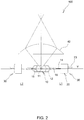
- the tips 15 formed to the light emission parts 12 of the respective light sources 10 of both the light source arrays L1, L2 are arranged in the same plane (plane Y indicated by an alternate long and two short dashes line in Fig. 2 ), and the cylindrical lens 40 is installed on one side with respect to the plane Y.
- the cylindrical lens 40 is arranged such that the flat surface side is on the respective light sources 10 side and in parallel with the plane Y and the central axis line is in parallel with the straight line X, and linearly condenses the light emitted from the respective light sources 10. Accordingly, in the linear light irradiation device 100, the installation side of the cylindrical lens 40 corresponds to an emission direction of the linear light.
- the tips 15 of the light sources 10 are ones formed when the light emission parts 12 are sealed, but are not necessarily formed in the same shape, and arranging the tips 15 of the respective light sources 10 in the same plane also includes slight displacement from the same plane due to such differences in shape among the respective tips 15.
- the emission direction of the linear light corresponds to a direction orthogonal to directions from the filaments 11 toward the tips 15 of the respective light sources 10, and therefore among the light emitted from the filaments 11 of the respective light sources 10, light passing through tips 15 causing stray light is difficult to reach in the emission direction of the linear light, improving the optical accuracy of the linear light.
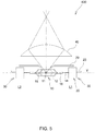
- a linear light irradiation device 200 is a variation of the above-described linear light irradiation device 100. As illustrated in Fig. 3(a) , the linear light irradiation device 200 is configured to arrange a mirror 50, which reflects the light emitted from the respective light sources 10, on the side opposite to the irradiation side of the linear light with respect to the respective light sources 10 (on the other side with respect to the plane Y).
- the mirror 50 is arranged with a concave curved surface of a semi-arc shape directed toward the respective light sources 10 side, and a centerline on the concave curved surface side is provided in parallel with the straight line X.
- the mirror 50 reflects the light emitted from the respective light sources 10 toward the cylindrical lens 40 side (emission direction side of the linear light) so as to pass the light through the filaments 11.
- the mirror 50 is preferably formed of aluminum having high infrared light reflectance.
- the linear light irradiation device 200 not only light emitted from the respective light sources 10 toward the one side with respect to the plane Y, but light emitted toward the other side can also be used as the linear light, making it possible to increase the intensity of the linear light.
- a number of fins 51 may be provided on the opposite side surface to the concave curved surface of the mirror 50 to add a role as a heat sink for radiating heat generated in the mirror 50.
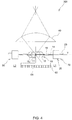
- a linear light irradiation device 300 is a variation of the above-described linear light irradiation device 100. As illustrated in Fig. 4 , the linear light irradiation device 300 is configured to arrange an antireflection member 60, which prevents the reflection of the light emitted from the respective light sources 10, on the side opposite to the irradiation side of the linear light with respect to the respective light sources 10 (on the other side with respect to the plane Y). In addition, a surface of the antireflection member 60 facing the respective light sources 10 side is applied with antireflection treatment by graphite coating, and the opposite side surface is provided with a number of fins 61 to play a role as a heat sink as well.
- the antireflection member 60 prevents the reflection of the light emitted from the respective light sources 10 in a direction opposite to the emission direction of the linear light, and therefore stray light is eliminated, thus improving optical accuracy.
- a linear light irradiation device 400 according to the present embodiment is a variation of the above-described linear light irradiation device 100.
- the linear light irradiation device 400 is configured to arrange a shielding member 70, which prevents light passing through the tips 15 and their surroundings among the light emitted from the filaments 11 of the respective light sources 10 from reaching the emission side of the linear light, on the emission side of the linear light with respect to the respective light sources 10 (on the one side with respect to the plane Y) and between the respective light sources 10 and the cylindrical lens 40.
- the shielding member 70 is formed of plate materials installed for the respective light source arrays L1, L2, and formed in a shape in which parts of the respective plate materials opposite to the tips 15 are bent toward the respective light sources 10 side.
- the linear light irradiation device 400 According to the linear light irradiation device 400, the light passing through the tips 15 of the respective light sources 10 and their surroundings causing stray light is eliminated by the shielding member 70, thus making it possible to improve optical accuracy. Also, the presence of the shielding member 70 can also prevent damage to wiring.
- a linear light irradiation device 500 is a variation of the above-described linear light irradiation device 100.
- the first light source array and the second light source array are circular-shaped, and along with this, the filaments 11 of all the light sources 10 are provided on the same circle (circle C indicated by alternate long and short dash line in Fig. 6 ).
- the first light source array and the second light source array may be ones of another curvilinear shape, and in this case, the filaments 11 of all the light sources 10 are provided in the same curved line.
- the tips 15 of the respective light sources 10 of both the light source arrays L1, 12, and the filaments 11 of the respective light sources 10 of both the light source arrays L1, L2 are arranged in an posture of being provided in the same plane, and one side of the plane is set as the emission direction of the linear light; however, as illustrated in Fig.
- the tips 15 of the respective light sources 10 of both the light source arrays L1, L2, and the filaments 11 of the respective light sources 10 of both the light source arrays L1, L2 may be arranged in postures of being provided in the same plane and not being provided in the plane, respectively, and one side of the plane may be set as the emission direction of the linear light. Further, part or all of the light sources 10 of both the light source arrays L1, L2 may be arranged in respectively different postures.
- the light emitted from the respective light sources 10 is condensed in a linear shape by the cylindrical lens 40; however, as illustrated in Fig. 8 , the light emitted from the respective light sources 10 may be condensed by a reflective mirror 80.
- the reflective mirror 80 is arranged on the emission direction side of the linear light with respect to the light sources 10, and has a reflective surface of a curved surface shape.
- the filaments 11 of the respective light sources 10 only have to be positions on the same straight line or on the same arc as viewed from on the optical axis (emission direction side) of the linear light, and for example, may be in a posture of being tilted to some extent as viewed from a direction orthogonal to the optical axis.
- a bandpass filter may be arranged on the emission direction side of the linear light with respect to the lens, and from among the light emitted from the lens, only light in a specific wavelength range may be used as the linear light.
- the light emitted from the respective light sources 10 is condensed in a linear shape by the cylindrical lens 40; however, the light emitted from the respective light sources 10 may be converted to parallel beams by the cylindrical lens 40.
- halogen lamps are used; however, without limitation to this, it is only necessary to be incandescent lamps utilizing filament radiation due to Joule heat, and Krypton lamps or the like can also be used.
- the light source one whose light emission part is connected to the socket via the terminals is used; however, the light source is not limited to this, but may be one whose light emission part is directly connected to the socket without any terminal.
- a conventionally commercially available, highly reliable, and inexpensive socket can be directly used, and the working effects of the present invention can be obtained without an increase in cost.
Landscapes
- General Health & Medical Sciences (AREA)
- Physics & Mathematics (AREA)
- Life Sciences & Earth Sciences (AREA)
- Chemical & Material Sciences (AREA)
- Analytical Chemistry (AREA)
- Biochemistry (AREA)
- Health & Medical Sciences (AREA)
- General Physics & Mathematics (AREA)
- Engineering & Computer Science (AREA)
- Pathology (AREA)
- Immunology (AREA)
- General Engineering & Computer Science (AREA)
- Non-Portable Lighting Devices Or Systems Thereof (AREA)
- Fastening Of Light Sources Or Lamp Holders (AREA)
Description
- The present invention relates to a linear light irradiation device.
- A light source of a type that makes a filament emit light, such as a halogen lamp, has a wide wavelength range, emits light having high intensity up to an infrared range, and in this respect, is superior to LEDs, so it is still now used as a light source for irradiating test objects with infrared light in a contamination test, a visual test, and the like using an infrared camera.
- As a conventional linear light irradiation device, for example, like a linear light irradiation device disclosed in
Patent Literature 1, there is one of a light source array type adapted to line up multiple halogen lamps whose terminals connected to sockets extend from light emission parts having filaments. - However, the above-described linear light irradiation device of a light source array type has had a problem that the sockets connected to the terminals of the halogen lamps are wider in width than the light emission parts of the halogen lamps to cause the sockets to impede light emission parts of adjacent halogen lamps from being arranged close together, a gap is created between adjacent light emission parts, and this makes the illuminance of linear light alternately strong and weak along a longitudinal direction to bring an irradiance distribution into an non-uniform state.
- On the other hand, as one having solved such a problem, like a linear light irradiation device disclosed in Patent Literature 2, there is one of a guide type that makes light emitted from a halogen lamp incident from one ends of optical fibers and emits it from the other ends of the optical fibers that are linearly arranged.
- However, the linear light irradiation of a guide type has had a problem that the light emitted from the halogen lamp repeats reflection in the optical fibers and is thereby attenuated to reduce the intensity of linear light, and the merits of the type making a filament emit light cannot be sufficiently utilized.
- As described, the conventional two types of linear light irradiation device respectively have both merits and demerits, and the development of a linear light irradiation device having only both the merits of them has been demanded.
-
- [Patent Literature 1]
Japanese Unexamined Utility Model PublicationJP-U56-60949 - [Patent Literature 2]
Japanese Unexamined Patent PublicationJP-A2002-288644 - Therefore, the main object of the present invention is to, in a linear light irradiation device using light sources of a type that makes a filament emit light, improve the uniformity of illuminance along the longitudinal direction of linear light, and while attenuating the intensity of light emitted from filaments as little as possible and keeping high intensity, perform irradiation.
- That is, the linear light irradiation device according to the present invention includes a first light source array and a second light source array each adapted to array multiple light sources each including a light emission part having a filament and a socket connected with the back end of the light emission part, in which at least the respective light sources of the first light source array and the respective light sources of the second light source array are alternately arranged along an array direction in respectively different postures, and the filaments of the respective light sources of both the light source arrays are provided on a straight line or on an arc parallel to the array direction as viewed from a predetermined direction.
- Such a configuration results in a state where in a gap formed between adjacent light sources arrayed in one light source array, a light source arrayed in the other light source array is arranged, and this makes it possible to narrow the arrangement interval between light sources, thus suppressing the strength/weakness (unevenness) of illuminance in the longitudinal direction of linear light. Also, since the respective light sources of both the light source arrays are provided on the same straight line or the same arc parallel as viewed from the predetermined direction, linear light close to linear light emitted from an elongated filament formed by connecting the filaments of the respective light sources can be reproduced, and this also makes it possible to obtain the linear light having highly uniform irradiance distribution. In addition, light emitted from the respective light sources can be used as the linear light without being attenuated, and therefore as with the above-described conventional linear light irradiation device of a light source array type, the linear light having high intensity can be obtained. Note that the predetermined direction is a direction in which the light sources are viewed from on the optical axis of the linear light.
- Also, in the linear light irradiation device, the sockets of the respective light sources of both the light source arrays may be ones interposing the straight line or the arc on which the filaments are arrayed and are provided on both sides of it. Further, the respective light sources of both the light source arrays may be ones provided in the same posture on a light source array basis, and the respective light sources of the first light source array and the respective light sources of the second light source array may be ones provided in directly opposite postures.
- In such a configuration, the sockets connected to the respective light sources of the first light source array and the sockets connected to the respective light sources of the second light source array can be separately arranged, thus making it possible to easily ensure an installation space and improve heat radiation performance.
- In addition, in the linear light irradiation device, the light emission parts of the respective light sources of both the light source arrays may be connected to respectively different sockets.
- In such a configuration, a conventionally commercially available, highly reliable, and inexpensive socket can be directly used, and the working effects of the present invention can be obtained without an increase in cost.
- According to the linear light irradiation device according to the present invention configured as described above, the strength/weakness of illuminance along the longitudinal direction of the linear light can be moderated, and the attenuation of the light emitted from the light sources occurring until reaching an object can be suppressed. This makes it possible to irradiate the object with the linear light having highly uniform illuminance distribution along the longitudinal direction and high intensity.
-
- [
Fig. 1 ]
Fig. 1 is a plan view illustrating a linear light irradiation device according to a first embodiment. - [
Fig. 2 ]
Fig. 2 is a side view illustrating the linear light irradiation device illustrated inFig. 1 . - [
Fig. 3 ]
Fig. 3 is a side view illustrating a linear light irradiation device according to a second embodiment. - [
Fig. 4 ]
Fig. 4 is a side view illustrating a linear light irradiation device according to a third embodiment. - [
Fig. 5 ]
Fig. 5 is a side view illustrating a linear light irradiation device according to a fourth embodiment. - [
Fig. 6 ]
Fig. 6 is a plan view illustrating a linear light irradiation device according to a fifth embodiment. - [
Fig. 7 ]
Fig. 7 is a side view illustrating a linear light irradiation device according to another embodiment. - [
Fig. 8 ]
Fig. 8 is a side view illustrating a linear light irradiation device according to another embodiment. -
- 100 Linear light irradiation device
- 10 Light source
- 20 Socket
- 30 Light source unit
- 40 Cylindrical lens
- 50 Mirror
- 60 Antireflection member
- 70 Shielding member
- In the following, the linear light irradiation device according to the present invention will be described with reference to the drawings.
- A linear
light irradiation device 100 according to the present embodiment is one used as a light source for, for example, irradiating a test object with infrared light when performing a contamination test, a visual test, or the like using an infrared camera. In addition, the application of the linear light irradiation device according to the present invention is not limited to the light source for the test, it is also usable for other applications, and the wavelength of light for the irradiation is also not limited at all. - As illustrated in
Fig. 1 orFig. 2 , the linearlight irradiation device 100 is configured to include: a first light source array L1 and a second light source array L2 each adapted to array multiplelight source units 30 each adapted to connect alight source 10 to asocket 20; and an cylindrical lens 40 (seeFig, 2 ) that condense light emitted from therespective light sources 10 of both the light source arrays L1 and L2. In addition, the first light source array L1 and the second light source array L2 are arranged in parallel. - The
light source 10 is a halogen lamp, and configured to include alight emission part 12 encapsulating afilament 11 and a pair ofterminals 14 connected to one ends of lead-in wires 13 extending from both ends of thefilament 11 and led outside thelight emission part 12. In addition, thelight emission part 12 is such that at least a filament encapsulating part is formed of glass, a tip 15 (glass fusion part) protrudes at one end of thelight emission part 12, and the other end of thelight emission part 12 is formed with a flat sealingpart 16 that interposes and seals the joining parts between the lead-in wires 13 and theterminals 14. Also, thefilament 11 is arranged perpendicular to a direction in which the pair ofterminals 14 extends. - The
socket 20 is configured to include: ablockish case body 22 having a pair of insertion ports 21 to be inserted with the pair ofterminals 14 extending from thelight source 10; andpower codes 23 led out of thecase body 22 and to be connected to an unillustrated power source. In addition, thecase body 22 is formed to be wider in width than thelight emission part 12 of thelight source 10. Further, power supplied from thepower codes 23 is transmitted to thefilament 11 through the pair ofterminals 14 and the pair of lead-in wires 13 via thesocket 20, and thereby Joule heat is generated in thefilament 11 to emit light. - The multiple
light source units 30 constituting the first light source array L1 are in a state of directing thelight emission parts 12 with respect to the pairs ofterminals 14, more specifically thetips 14 of thelight emission parts 12 toward the second light source array L2 side, and the respectivelight sources 10 are arranged in the same posture. Also, the multiplelight source units 30 constituting the second light source array L2 are in a state of directing thelight emission parts 12 with respect to the pairs ofterminals 14, more specifically thetips 15 of thelight emission parts 12 toward the first light source array L1 side, and the respectivelight sources 10 are arranged in the same posture. In addition, the respectivelight sources 10 of the first light source array L1 and the respectivelight source 10 of the second light source array L2 are alternately arranged along the array direction, and arranged in mutually directly opposite postures. In doing so, betweenlight emission parts 12 of adjacentlight sources 10 of one L1 (L2) of the light source arrays, alight emission part 12 of alight source 10 of the other light source array L2 (L1) is provided. In addition, thefilaments 11 of all thelight sources 10 are in a state where extension directions respectively coincide with the array direction, and provided on the same straight line (straight line X indicated by an alternate long and short dash line inFig. 1 ) extending in the array direction. In detail, thefilament 11 of each of thelight sources 10 is formed by spirally shaping a wire rod along the surface of a cylinder, and arranged such that the straight line X passes through the openings at both ends of the cylinder, and preferably coincides with the center axis of the cylinder. - Also, the
respective sockets 20 of the first light source array L1 and therespective sockets 20 of the second light source array L2 are arranged opposite with the straight line X as a center. Further, thelight emission parts 12 of the respectivelight sources 10 are arranged interposed between thesockets 20 of the first light source array L1 and thesockets 20 of the second light source array L2. - In addition, as illustrated in
Fig. 2 , thetips 15 formed to thelight emission parts 12 of the respectivelight sources 10 of both the light source arrays L1, L2 are arranged in the same plane (plane Y indicated by an alternate long and two short dashes line inFig. 2 ), and thecylindrical lens 40 is installed on one side with respect to the plane Y. Thecylindrical lens 40 is arranged such that the flat surface side is on the respectivelight sources 10 side and in parallel with the plane Y and the central axis line is in parallel with the straight line X, and linearly condenses the light emitted from the respectivelight sources 10. Accordingly, in the linearlight irradiation device 100, the installation side of thecylindrical lens 40 corresponds to an emission direction of the linear light. In addition, thetips 15 of thelight sources 10 are ones formed when thelight emission parts 12 are sealed, but are not necessarily formed in the same shape, and arranging thetips 15 of the respectivelight sources 10 in the same plane also includes slight displacement from the same plane due to such differences in shape among therespective tips 15. - By configuring as described above, the emission direction of the linear light corresponds to a direction orthogonal to directions from the
filaments 11 toward thetips 15 of the respectivelight sources 10, and therefore among the light emitted from thefilaments 11 of the respectivelight sources 10, light passing throughtips 15 causing stray light is difficult to reach in the emission direction of the linear light, improving the optical accuracy of the linear light. - A linear
light irradiation device 200 according to the present embodiment is a variation of the above-described linearlight irradiation device 100. As illustrated inFig. 3(a) , the linearlight irradiation device 200 is configured to arrange amirror 50, which reflects the light emitted from the respectivelight sources 10, on the side opposite to the irradiation side of the linear light with respect to the respective light sources 10 (on the other side with respect to the plane Y). - The
mirror 50 is arranged with a concave curved surface of a semi-arc shape directed toward the respectivelight sources 10 side, and a centerline on the concave curved surface side is provided in parallel with the straight line X. In addition, themirror 50 reflects the light emitted from the respectivelight sources 10 toward thecylindrical lens 40 side (emission direction side of the linear light) so as to pass the light through thefilaments 11. Further, themirror 50 is preferably formed of aluminum having high infrared light reflectance. - According to the linear
light irradiation device 200, not only light emitted from the respectivelight sources 10 toward the one side with respect to the plane Y, but light emitted toward the other side can also be used as the linear light, making it possible to increase the intensity of the linear light. - In addition, in the linear
light irradiation device 200, as illustrated inFig. 3(b) , a number offins 51 may be provided on the opposite side surface to the concave curved surface of themirror 50 to add a role as a heat sink for radiating heat generated in themirror 50. - A linear
light irradiation device 300 according to the present embodiment is a variation of the above-described linearlight irradiation device 100. As illustrated inFig. 4 , the linearlight irradiation device 300 is configured to arrange anantireflection member 60, which prevents the reflection of the light emitted from the respectivelight sources 10, on the side opposite to the irradiation side of the linear light with respect to the respective light sources 10 (on the other side with respect to the plane Y). In addition, a surface of theantireflection member 60 facing the respectivelight sources 10 side is applied with antireflection treatment by graphite coating, and the opposite side surface is provided with a number offins 61 to play a role as a heat sink as well. - According to the linear
light irradiation device 300, theantireflection member 60 prevents the reflection of the light emitted from the respectivelight sources 10 in a direction opposite to the emission direction of the linear light, and therefore stray light is eliminated, thus improving optical accuracy. - A linear
light irradiation device 400 according to the present embodiment is a variation of the above-described linearlight irradiation device 100. As illustrated inFig. 5 , the linearlight irradiation device 400 is configured to arrange a shieldingmember 70, which prevents light passing through thetips 15 and their surroundings among the light emitted from thefilaments 11 of the respectivelight sources 10 from reaching the emission side of the linear light, on the emission side of the linear light with respect to the respective light sources 10 (on the one side with respect to the plane Y) and between the respectivelight sources 10 and thecylindrical lens 40. In addition, the shieldingmember 70 is formed of plate materials installed for the respective light source arrays L1, L2, and formed in a shape in which parts of the respective plate materials opposite to thetips 15 are bent toward the respectivelight sources 10 side. - According to the linear
light irradiation device 400, the light passing through thetips 15 of the respectivelight sources 10 and their surroundings causing stray light is eliminated by the shieldingmember 70, thus making it possible to improve optical accuracy. Also, the presence of the shieldingmember 70 can also prevent damage to wiring. - A linear
light irradiation device 500 according to the present embodiment is a variation of the above-described linearlight irradiation device 100. As illustrated inFig. 6 , in the linearlight irradiation device 500, the first light source array and the second light source array are circular-shaped, and along with this, thefilaments 11 of all thelight sources 10 are provided on the same circle (circle C indicated by alternate long and short dash line inFig. 6 ). In addition, although not illustrated, the first light source array and the second light source array may be ones of another curvilinear shape, and in this case, thefilaments 11 of all thelight sources 10 are provided in the same curved line. - In each of the above-described embodiments, in order to eliminate as much as possible the influence of the light passing through the
tips 15 among the light emitted from thefilaments 11 of the respectivelight sources 10, thetips 15 of the respectivelight sources 10 of both the light source arrays L1, 12, and thefilaments 11 of the respectivelight sources 10 of both the light source arrays L1, L2 are arranged in an posture of being provided in the same plane, and one side of the plane is set as the emission direction of the linear light; however, as illustrated inFig. 7 , thetips 15 of the respectivelight sources 10 of both the light source arrays L1, L2, and thefilaments 11 of the respectivelight sources 10 of both the light source arrays L1, L2 may be arranged in postures of being provided in the same plane and not being provided in the plane, respectively, and one side of the plane may be set as the emission direction of the linear light. Further, part or all of thelight sources 10 of both the light source arrays L1, L2 may be arranged in respectively different postures. - In each of the above-described embodiments, the light emitted from the respective
light sources 10 is condensed in a linear shape by thecylindrical lens 40; however, as illustrated inFig. 8 , the light emitted from the respectivelight sources 10 may be condensed by areflective mirror 80. In addition, thereflective mirror 80 is arranged on the emission direction side of the linear light with respect to thelight sources 10, and has a reflective surface of a curved surface shape. - The
filaments 11 of the respectivelight sources 10 only have to be positions on the same straight line or on the same arc as viewed from on the optical axis (emission direction side) of the linear light, and for example, may be in a posture of being tilted to some extent as viewed from a direction orthogonal to the optical axis. - In each of the above-described embodiment, a bandpass filter may be arranged on the emission direction side of the linear light with respect to the lens, and from among the light emitted from the lens, only light in a specific wavelength range may be used as the linear light.
- In each of the above-described embodiment, the light emitted from the respective
light sources 10 is condensed in a linear shape by thecylindrical lens 40; however, the light emitted from the respectivelight sources 10 may be converted to parallel beams by thecylindrical lens 40. - In addition, in each of the above-described embodiments, as the light sources, halogen lamps are used; however, without limitation to this, it is only necessary to be incandescent lamps utilizing filament radiation due to Joule heat, and Krypton lamps or the like can also be used. Also, in each of the above-described embodiments, as the light source, one whose light emission part is connected to the socket via the terminals is used; however, the light source is not limited to this, but may be one whose light emission part is directly connected to the socket without any terminal.
- Besides, the present invention is not limited to the above-described embodiments, but can be variously modified without departing from the scope thereof, and components in the respective embodiments may be appropriately combined.
- According to the present invention, a conventionally commercially available, highly reliable, and inexpensive socket can be directly used, and the working effects of the present invention can be obtained without an increase in cost.
Claims (4)
- A linear light irradiation device (100) comprising a first light source array (L1) and a second light source array (L2), the first and second light source arrays (L1, L2) each being adapted to array multiple light sources (10) each comprising a light emission part (12) having a filament (11) and a socket (20) connected with a back end of the light emission part (12), wherein at least the respective light sources (10) of the first light source array (L1) and the respective light sources (10) of the second light source array (L2) are alternately arranged along an array direction in respectively different postures, and the filaments (11) of the respective light sources (10) of both the light source arrays (L1, L2) are provided on a straight line or on an arc parallel to the array direction as viewed from a predetermined direction.
- The linear light irradiation device (100) according to claim 1, wherein the sockets (20) of the respective light sources (10) of both the light source arrays (L1, L2) interpose the straight line or the arc on which the filaments are arrayed and are provided on both sides of it.
- The linear light irradiation device (100) according to claim 1, wherein the respective light sources (10) of both the light source arrays (L1,L2) are provided in a same posture on a light source array basis, and the respective light sources (10) of the first light source array (L1) and the respective light sources (10) of the second light source array (L2) are provided in directly opposite postures.
- The linear light irradiation device according to claim 1, wherein the light emission parts (12) of the respective light sources (10) of both the light source arrays (L1,L2) are connected to respectively different sockets (30).
Applications Claiming Priority (2)
| Application Number | Priority Date | Filing Date | Title |
|---|---|---|---|
| JP2016253894A JP6756608B2 (en) | 2016-12-27 | 2016-12-27 | Line light irradiation device |
| PCT/JP2017/046569 WO2018124037A1 (en) | 2016-12-27 | 2017-12-26 | Linear light irradiation device |
Publications (3)
| Publication Number | Publication Date |
|---|---|
| EP3564657A1 EP3564657A1 (en) | 2019-11-06 |
| EP3564657A4 EP3564657A4 (en) | 2020-08-12 |
| EP3564657B1 true EP3564657B1 (en) | 2021-05-26 |
Family
ID=62710261
Family Applications (1)
| Application Number | Title | Priority Date | Filing Date |
|---|---|---|---|
| EP17886968.1A Active EP3564657B1 (en) | 2016-12-27 | 2017-12-26 | Linear light irradiation device |
Country Status (3)
| Country | Link |
|---|---|
| EP (1) | EP3564657B1 (en) |
| JP (1) | JP6756608B2 (en) |
| WO (1) | WO2018124037A1 (en) |
Families Citing this family (1)
| Publication number | Priority date | Publication date | Assignee | Title |
|---|---|---|---|---|
| JP7217702B2 (en) * | 2017-06-12 | 2023-02-03 | シーシーエス株式会社 | lighting equipment |
Family Cites Families (6)
| Publication number | Priority date | Publication date | Assignee | Title |
|---|---|---|---|---|
| JPS609788Y2 (en) | 1979-10-15 | 1985-04-05 | 株式会社リコー | Slit exposure type illumination device |
| JPH07320521A (en) * | 1994-05-19 | 1995-12-08 | Nippondenso Co Ltd | Lamp fixing structure |
| JP2002208466A (en) * | 2001-01-05 | 2002-07-26 | Tokyo Electron Ltd | Heating lamp and heat treatment device |
| JP4397130B2 (en) | 2001-03-26 | 2010-01-13 | 株式会社住田光学ガラス | Line type lighting device |
| JP4893474B2 (en) * | 2007-05-29 | 2012-03-07 | ウシオ電機株式会社 | Filament lamp and light irradiation type heat treatment equipment |
| TWI359245B (en) * | 2008-10-27 | 2012-03-01 | Univ Chung Hua | Machine vision inspection system and light source |
-
2016
- 2016-12-27 JP JP2016253894A patent/JP6756608B2/en active Active
-
2017
- 2017-12-26 WO PCT/JP2017/046569 patent/WO2018124037A1/en unknown
- 2017-12-26 EP EP17886968.1A patent/EP3564657B1/en active Active
Also Published As
| Publication number | Publication date |
|---|---|
| EP3564657A4 (en) | 2020-08-12 |
| EP3564657A1 (en) | 2019-11-06 |
| JP6756608B2 (en) | 2020-09-16 |
| WO2018124037A1 (en) | 2018-07-05 |
| JP2018107004A (en) | 2018-07-05 |
Similar Documents
| Publication | Publication Date | Title |
|---|---|---|
| CN108351084B (en) | Lighting device for motor vehicle searchlight | |
| US20180135810A1 (en) | Led filament for omnidirectional lamp | |
| KR101177937B1 (en) | Led lamp with central optical light guide | |
| US10544910B2 (en) | Lighting device with LED filaments | |
| KR20090126189A (en) | Rear-loaded light emitting diode module for automotive rear combination lamps | |
| JP2020518974A5 (en) | ||
| JP6351881B1 (en) | Light emitting device combining light from multiple LEDs | |
| JP2011054759A (en) | Wavelength converting member-holding member and method of manufacturing the same, heat radiation structure of the wavelength converting member, and light-emitting device | |
| CN106958747B (en) | Light irradiation device | |
| US20160138765A1 (en) | Led lighting device with improved light distribution | |
| EP3564657B1 (en) | Linear light irradiation device | |
| JP3166555U (en) | Lamp ballast module and lamp module | |
| US20210180759A1 (en) | Homogeneous light emission and light guide arrangement of an automobile vehicle for a uniform lit appearance | |
| CN100454044C (en) | Light source even optical fibre low-waste conduction projector | |
| KR102085955B1 (en) | A lighting device using a led | |
| EP1652214B1 (en) | Electric lamp | |
| CN108633297A (en) | Searchlight for motor vehicle | |
| JP6507008B2 (en) | Light guide and light emitting device | |
| US10596543B2 (en) | Light illuminating apparatus | |
| KR20110134498A (en) | Led collimation optics module providing an isolation fitting | |
| US20190003680A1 (en) | Led lamp | |
| AU2018282844B2 (en) | Illumination device | |
| JP4814305B2 (en) | Light bulb with shielding device | |
| JP7090020B2 (en) | Line light irradiation device | |
| KR102565789B1 (en) | LED bulb lamps and automotive lamp comprising the same |
Legal Events
| Date | Code | Title | Description |
|---|---|---|---|
| STAA | Information on the status of an ep patent application or granted ep patent |
Free format text: STATUS: THE INTERNATIONAL PUBLICATION HAS BEEN MADE |
|
| PUAI | Public reference made under article 153(3) epc to a published international application that has entered the european phase |
Free format text: ORIGINAL CODE: 0009012 |
|
| STAA | Information on the status of an ep patent application or granted ep patent |
Free format text: STATUS: REQUEST FOR EXAMINATION WAS MADE |
|
| 17P | Request for examination filed |
Effective date: 20190710 |
|
| AK | Designated contracting states |
Kind code of ref document: A1 Designated state(s): AL AT BE BG CH CY CZ DE DK EE ES FI FR GB GR HR HU IE IS IT LI LT LU LV MC MK MT NL NO PL PT RO RS SE SI SK SM TR |
|
| AX | Request for extension of the european patent |
Extension state: BA ME |
|
| DAV | Request for validation of the european patent (deleted) | ||
| DAX | Request for extension of the european patent (deleted) | ||
| A4 | Supplementary search report drawn up and despatched |
Effective date: 20200714 |
|
| RIC1 | Information provided on ipc code assigned before grant |
Ipc: F21Y 101/00 20160101ALI20200708BHEP Ipc: F21Y 103/10 20160101ALI20200708BHEP Ipc: F21S 2/00 20160101ALI20200708BHEP Ipc: F21Y 103/33 20160101ALI20200708BHEP Ipc: F21V 19/00 20060101ALI20200708BHEP Ipc: G01N 21/84 20060101AFI20200708BHEP |
|
| GRAP | Despatch of communication of intention to grant a patent |
Free format text: ORIGINAL CODE: EPIDOSNIGR1 |
|
| STAA | Information on the status of an ep patent application or granted ep patent |
Free format text: STATUS: GRANT OF PATENT IS INTENDED |
|
| INTG | Intention to grant announced |
Effective date: 20201214 |
|
| GRAS | Grant fee paid |
Free format text: ORIGINAL CODE: EPIDOSNIGR3 |
|
| GRAA | (expected) grant |
Free format text: ORIGINAL CODE: 0009210 |
|
| STAA | Information on the status of an ep patent application or granted ep patent |
Free format text: STATUS: THE PATENT HAS BEEN GRANTED |
|
| AK | Designated contracting states |
Kind code of ref document: B1 Designated state(s): AL AT BE BG CH CY CZ DE DK EE ES FI FR GB GR HR HU IE IS IT LI LT LU LV MC MK MT NL NO PL PT RO RS SE SI SK SM TR |
|
| REG | Reference to a national code |
Ref country code: GB Ref legal event code: FG4D |
|
| REG | Reference to a national code |
Ref country code: CH Ref legal event code: EP |
|
| REG | Reference to a national code |
Ref country code: DE Ref legal event code: R096 Ref document number: 602017039485 Country of ref document: DE |
|
| REG | Reference to a national code |
Ref country code: AT Ref legal event code: REF Ref document number: 1396720 Country of ref document: AT Kind code of ref document: T Effective date: 20210615 |
|
| REG | Reference to a national code |
Ref country code: IE Ref legal event code: FG4D |
|
| REG | Reference to a national code |
Ref country code: LT Ref legal event code: MG9D |
|
| REG | Reference to a national code |
Ref country code: AT Ref legal event code: MK05 Ref document number: 1396720 Country of ref document: AT Kind code of ref document: T Effective date: 20210526 |
|
| PG25 | Lapsed in a contracting state [announced via postgrant information from national office to epo] |
Ref country code: HR Free format text: LAPSE BECAUSE OF FAILURE TO SUBMIT A TRANSLATION OF THE DESCRIPTION OR TO PAY THE FEE WITHIN THE PRESCRIBED TIME-LIMIT Effective date: 20210526 Ref country code: BG Free format text: LAPSE BECAUSE OF FAILURE TO SUBMIT A TRANSLATION OF THE DESCRIPTION OR TO PAY THE FEE WITHIN THE PRESCRIBED TIME-LIMIT Effective date: 20210826 Ref country code: AT Free format text: LAPSE BECAUSE OF FAILURE TO SUBMIT A TRANSLATION OF THE DESCRIPTION OR TO PAY THE FEE WITHIN THE PRESCRIBED TIME-LIMIT Effective date: 20210526 Ref country code: LT Free format text: LAPSE BECAUSE OF FAILURE TO SUBMIT A TRANSLATION OF THE DESCRIPTION OR TO PAY THE FEE WITHIN THE PRESCRIBED TIME-LIMIT Effective date: 20210526 Ref country code: FI Free format text: LAPSE BECAUSE OF FAILURE TO SUBMIT A TRANSLATION OF THE DESCRIPTION OR TO PAY THE FEE WITHIN THE PRESCRIBED TIME-LIMIT Effective date: 20210526 |
|
| REG | Reference to a national code |
Ref country code: NL Ref legal event code: MP Effective date: 20210526 |
|
| PG25 | Lapsed in a contracting state [announced via postgrant information from national office to epo] |
Ref country code: GR Free format text: LAPSE BECAUSE OF FAILURE TO SUBMIT A TRANSLATION OF THE DESCRIPTION OR TO PAY THE FEE WITHIN THE PRESCRIBED TIME-LIMIT Effective date: 20210827 Ref country code: IS Free format text: LAPSE BECAUSE OF FAILURE TO SUBMIT A TRANSLATION OF THE DESCRIPTION OR TO PAY THE FEE WITHIN THE PRESCRIBED TIME-LIMIT Effective date: 20210926 Ref country code: PT Free format text: LAPSE BECAUSE OF FAILURE TO SUBMIT A TRANSLATION OF THE DESCRIPTION OR TO PAY THE FEE WITHIN THE PRESCRIBED TIME-LIMIT Effective date: 20210927 Ref country code: LV Free format text: LAPSE BECAUSE OF FAILURE TO SUBMIT A TRANSLATION OF THE DESCRIPTION OR TO PAY THE FEE WITHIN THE PRESCRIBED TIME-LIMIT Effective date: 20210526 Ref country code: NO Free format text: LAPSE BECAUSE OF FAILURE TO SUBMIT A TRANSLATION OF THE DESCRIPTION OR TO PAY THE FEE WITHIN THE PRESCRIBED TIME-LIMIT Effective date: 20210826 Ref country code: PL Free format text: LAPSE BECAUSE OF FAILURE TO SUBMIT A TRANSLATION OF THE DESCRIPTION OR TO PAY THE FEE WITHIN THE PRESCRIBED TIME-LIMIT Effective date: 20210526 Ref country code: SE Free format text: LAPSE BECAUSE OF FAILURE TO SUBMIT A TRANSLATION OF THE DESCRIPTION OR TO PAY THE FEE WITHIN THE PRESCRIBED TIME-LIMIT Effective date: 20210526 Ref country code: RS Free format text: LAPSE BECAUSE OF FAILURE TO SUBMIT A TRANSLATION OF THE DESCRIPTION OR TO PAY THE FEE WITHIN THE PRESCRIBED TIME-LIMIT Effective date: 20210526 |
|
| PG25 | Lapsed in a contracting state [announced via postgrant information from national office to epo] |
Ref country code: NL Free format text: LAPSE BECAUSE OF FAILURE TO SUBMIT A TRANSLATION OF THE DESCRIPTION OR TO PAY THE FEE WITHIN THE PRESCRIBED TIME-LIMIT Effective date: 20210526 |
|
| PG25 | Lapsed in a contracting state [announced via postgrant information from national office to epo] |
Ref country code: SK Free format text: LAPSE BECAUSE OF FAILURE TO SUBMIT A TRANSLATION OF THE DESCRIPTION OR TO PAY THE FEE WITHIN THE PRESCRIBED TIME-LIMIT Effective date: 20210526 Ref country code: SM Free format text: LAPSE BECAUSE OF FAILURE TO SUBMIT A TRANSLATION OF THE DESCRIPTION OR TO PAY THE FEE WITHIN THE PRESCRIBED TIME-LIMIT Effective date: 20210526 Ref country code: ES Free format text: LAPSE BECAUSE OF FAILURE TO SUBMIT A TRANSLATION OF THE DESCRIPTION OR TO PAY THE FEE WITHIN THE PRESCRIBED TIME-LIMIT Effective date: 20210526 Ref country code: EE Free format text: LAPSE BECAUSE OF FAILURE TO SUBMIT A TRANSLATION OF THE DESCRIPTION OR TO PAY THE FEE WITHIN THE PRESCRIBED TIME-LIMIT Effective date: 20210526 Ref country code: RO Free format text: LAPSE BECAUSE OF FAILURE TO SUBMIT A TRANSLATION OF THE DESCRIPTION OR TO PAY THE FEE WITHIN THE PRESCRIBED TIME-LIMIT Effective date: 20210526 Ref country code: DK Free format text: LAPSE BECAUSE OF FAILURE TO SUBMIT A TRANSLATION OF THE DESCRIPTION OR TO PAY THE FEE WITHIN THE PRESCRIBED TIME-LIMIT Effective date: 20210526 Ref country code: CZ Free format text: LAPSE BECAUSE OF FAILURE TO SUBMIT A TRANSLATION OF THE DESCRIPTION OR TO PAY THE FEE WITHIN THE PRESCRIBED TIME-LIMIT Effective date: 20210526 |
|
| REG | Reference to a national code |
Ref country code: DE Ref legal event code: R097 Ref document number: 602017039485 Country of ref document: DE |
|
| PLBE | No opposition filed within time limit |
Free format text: ORIGINAL CODE: 0009261 |
|
| STAA | Information on the status of an ep patent application or granted ep patent |
Free format text: STATUS: NO OPPOSITION FILED WITHIN TIME LIMIT |
|
| 26N | No opposition filed |
Effective date: 20220301 |
|
| PG25 | Lapsed in a contracting state [announced via postgrant information from national office to epo] |
Ref country code: IS Free format text: LAPSE BECAUSE OF FAILURE TO SUBMIT A TRANSLATION OF THE DESCRIPTION OR TO PAY THE FEE WITHIN THE PRESCRIBED TIME-LIMIT Effective date: 20210926 Ref country code: AL Free format text: LAPSE BECAUSE OF FAILURE TO SUBMIT A TRANSLATION OF THE DESCRIPTION OR TO PAY THE FEE WITHIN THE PRESCRIBED TIME-LIMIT Effective date: 20210526 |
|
| PG25 | Lapsed in a contracting state [announced via postgrant information from national office to epo] |
Ref country code: MC Free format text: LAPSE BECAUSE OF FAILURE TO SUBMIT A TRANSLATION OF THE DESCRIPTION OR TO PAY THE FEE WITHIN THE PRESCRIBED TIME-LIMIT Effective date: 20210526 Ref country code: IT Free format text: LAPSE BECAUSE OF FAILURE TO SUBMIT A TRANSLATION OF THE DESCRIPTION OR TO PAY THE FEE WITHIN THE PRESCRIBED TIME-LIMIT Effective date: 20210526 |
|
| REG | Reference to a national code |
Ref country code: CH Ref legal event code: PL |
|
| GBPC | Gb: european patent ceased through non-payment of renewal fee |
Effective date: 20211226 |
|
| REG | Reference to a national code |
Ref country code: BE Ref legal event code: MM Effective date: 20211231 |
|
| PG25 | Lapsed in a contracting state [announced via postgrant information from national office to epo] |
Ref country code: LU Free format text: LAPSE BECAUSE OF NON-PAYMENT OF DUE FEES Effective date: 20211226 Ref country code: IE Free format text: LAPSE BECAUSE OF NON-PAYMENT OF DUE FEES Effective date: 20211226 Ref country code: GB Free format text: LAPSE BECAUSE OF NON-PAYMENT OF DUE FEES Effective date: 20211226 |
|
| PG25 | Lapsed in a contracting state [announced via postgrant information from national office to epo] |
Ref country code: BE Free format text: LAPSE BECAUSE OF NON-PAYMENT OF DUE FEES Effective date: 20211231 |
|
| PG25 | Lapsed in a contracting state [announced via postgrant information from national office to epo] |
Ref country code: LI Free format text: LAPSE BECAUSE OF NON-PAYMENT OF DUE FEES Effective date: 20211231 Ref country code: CH Free format text: LAPSE BECAUSE OF NON-PAYMENT OF DUE FEES Effective date: 20211231 |
|
| PG25 | Lapsed in a contracting state [announced via postgrant information from national office to epo] |
Ref country code: CY Free format text: LAPSE BECAUSE OF FAILURE TO SUBMIT A TRANSLATION OF THE DESCRIPTION OR TO PAY THE FEE WITHIN THE PRESCRIBED TIME-LIMIT Effective date: 20210526 |
|
| PG25 | Lapsed in a contracting state [announced via postgrant information from national office to epo] |
Ref country code: HU Free format text: LAPSE BECAUSE OF FAILURE TO SUBMIT A TRANSLATION OF THE DESCRIPTION OR TO PAY THE FEE WITHIN THE PRESCRIBED TIME-LIMIT; INVALID AB INITIO Effective date: 20171226 |
|
| PGFP | Annual fee paid to national office [announced via postgrant information from national office to epo] |
Ref country code: FR Payment date: 20231219 Year of fee payment: 7 Ref country code: DE Payment date: 20231218 Year of fee payment: 7 |
|
| PG25 | Lapsed in a contracting state [announced via postgrant information from national office to epo] |
Ref country code: MK Free format text: LAPSE BECAUSE OF FAILURE TO SUBMIT A TRANSLATION OF THE DESCRIPTION OR TO PAY THE FEE WITHIN THE PRESCRIBED TIME-LIMIT Effective date: 20210526 |