EP3564652A1 - Laser radar device - Google Patents
Laser radar device Download PDFInfo
- Publication number
- EP3564652A1 EP3564652A1 EP17894031.8A EP17894031A EP3564652A1 EP 3564652 A1 EP3564652 A1 EP 3564652A1 EP 17894031 A EP17894031 A EP 17894031A EP 3564652 A1 EP3564652 A1 EP 3564652A1
- Authority
- EP
- European Patent Office
- Prior art keywords
- signal
- light beam
- spectrum
- unit
- laser light
- Prior art date
- Legal status (The legal status is an assumption and is not a legal conclusion. Google has not performed a legal analysis and makes no representation as to the accuracy of the status listed.)
- Granted
Links
- 238000001228 spectrum Methods 0.000 claims abstract description 402
- 230000003287 optical effect Effects 0.000 claims description 163
- 238000012545 processing Methods 0.000 claims description 77
- 230000010354 integration Effects 0.000 claims description 72
- 238000000034 method Methods 0.000 claims description 55
- 230000001131 transforming effect Effects 0.000 claims description 35
- 238000010521 absorption reaction Methods 0.000 description 57
- 239000000443 aerosol Substances 0.000 description 33
- 238000010586 diagram Methods 0.000 description 18
- 230000003321 amplification Effects 0.000 description 16
- 238000003199 nucleic acid amplification method Methods 0.000 description 16
- 230000006866 deterioration Effects 0.000 description 9
- 239000013307 optical fiber Substances 0.000 description 8
- 238000000862 absorption spectrum Methods 0.000 description 6
- 238000012937 correction Methods 0.000 description 6
- 238000001514 detection method Methods 0.000 description 6
- 230000000694 effects Effects 0.000 description 5
- CURLTUGMZLYLDI-UHFFFAOYSA-N Carbon dioxide Chemical compound O=C=O CURLTUGMZLYLDI-UHFFFAOYSA-N 0.000 description 2
- 239000004065 semiconductor Substances 0.000 description 2
- 229910002092 carbon dioxide Inorganic materials 0.000 description 1
- 239000001569 carbon dioxide Substances 0.000 description 1
- 239000002131 composite material Substances 0.000 description 1
- 239000013078 crystal Substances 0.000 description 1
- 239000000835 fiber Substances 0.000 description 1
- 230000006870 function Effects 0.000 description 1
- GQYHUHYESMUTHG-UHFFFAOYSA-N lithium niobate Chemical compound [Li+].[O-][Nb](=O)=O GQYHUHYESMUTHG-UHFFFAOYSA-N 0.000 description 1
- 238000005259 measurement Methods 0.000 description 1
- 238000012986 modification Methods 0.000 description 1
- 230000004048 modification Effects 0.000 description 1
- 230000010287 polarization Effects 0.000 description 1
- XLYOFNOQVPJJNP-UHFFFAOYSA-N water Chemical compound O XLYOFNOQVPJJNP-UHFFFAOYSA-N 0.000 description 1
Images


Classifications
-
- G—PHYSICS
- G01—MEASURING; TESTING
- G01S—RADIO DIRECTION-FINDING; RADIO NAVIGATION; DETERMINING DISTANCE OR VELOCITY BY USE OF RADIO WAVES; LOCATING OR PRESENCE-DETECTING BY USE OF THE REFLECTION OR RERADIATION OF RADIO WAVES; ANALOGOUS ARRANGEMENTS USING OTHER WAVES
- G01S7/00—Details of systems according to groups G01S13/00, G01S15/00, G01S17/00
- G01S7/48—Details of systems according to groups G01S13/00, G01S15/00, G01S17/00 of systems according to group G01S17/00
- G01S7/4802—Details of systems according to groups G01S13/00, G01S15/00, G01S17/00 of systems according to group G01S17/00 using analysis of echo signal for target characterisation; Target signature; Target cross-section
-
- G—PHYSICS
- G01—MEASURING; TESTING
- G01S—RADIO DIRECTION-FINDING; RADIO NAVIGATION; DETERMINING DISTANCE OR VELOCITY BY USE OF RADIO WAVES; LOCATING OR PRESENCE-DETECTING BY USE OF THE REFLECTION OR RERADIATION OF RADIO WAVES; ANALOGOUS ARRANGEMENTS USING OTHER WAVES
- G01S17/00—Systems using the reflection or reradiation of electromagnetic waves other than radio waves, e.g. lidar systems
- G01S17/02—Systems using the reflection of electromagnetic waves other than radio waves
- G01S17/06—Systems determining position data of a target
- G01S17/08—Systems determining position data of a target for measuring distance only
- G01S17/10—Systems determining position data of a target for measuring distance only using transmission of interrupted, pulse-modulated waves
-
- G—PHYSICS
- G01—MEASURING; TESTING
- G01S—RADIO DIRECTION-FINDING; RADIO NAVIGATION; DETERMINING DISTANCE OR VELOCITY BY USE OF RADIO WAVES; LOCATING OR PRESENCE-DETECTING BY USE OF THE REFLECTION OR RERADIATION OF RADIO WAVES; ANALOGOUS ARRANGEMENTS USING OTHER WAVES
- G01S17/00—Systems using the reflection or reradiation of electromagnetic waves other than radio waves, e.g. lidar systems
- G01S17/88—Lidar systems specially adapted for specific applications
- G01S17/95—Lidar systems specially adapted for specific applications for meteorological use
-
- G—PHYSICS
- G01—MEASURING; TESTING
- G01S—RADIO DIRECTION-FINDING; RADIO NAVIGATION; DETERMINING DISTANCE OR VELOCITY BY USE OF RADIO WAVES; LOCATING OR PRESENCE-DETECTING BY USE OF THE REFLECTION OR RERADIATION OF RADIO WAVES; ANALOGOUS ARRANGEMENTS USING OTHER WAVES
- G01S7/00—Details of systems according to groups G01S13/00, G01S15/00, G01S17/00
- G01S7/48—Details of systems according to groups G01S13/00, G01S15/00, G01S17/00 of systems according to group G01S17/00
- G01S7/4804—Auxiliary means for detecting or identifying lidar signals or the like, e.g. laser illuminators
-
- G—PHYSICS
- G01—MEASURING; TESTING
- G01S—RADIO DIRECTION-FINDING; RADIO NAVIGATION; DETERMINING DISTANCE OR VELOCITY BY USE OF RADIO WAVES; LOCATING OR PRESENCE-DETECTING BY USE OF THE REFLECTION OR RERADIATION OF RADIO WAVES; ANALOGOUS ARRANGEMENTS USING OTHER WAVES
- G01S7/00—Details of systems according to groups G01S13/00, G01S15/00, G01S17/00
- G01S7/48—Details of systems according to groups G01S13/00, G01S15/00, G01S17/00 of systems according to group G01S17/00
- G01S7/481—Constructional features, e.g. arrangements of optical elements
- G01S7/4811—Constructional features, e.g. arrangements of optical elements common to transmitter and receiver
- G01S7/4813—Housing arrangements
-
- G—PHYSICS
- G01—MEASURING; TESTING
- G01S—RADIO DIRECTION-FINDING; RADIO NAVIGATION; DETERMINING DISTANCE OR VELOCITY BY USE OF RADIO WAVES; LOCATING OR PRESENCE-DETECTING BY USE OF THE REFLECTION OR RERADIATION OF RADIO WAVES; ANALOGOUS ARRANGEMENTS USING OTHER WAVES
- G01S7/00—Details of systems according to groups G01S13/00, G01S15/00, G01S17/00
- G01S7/48—Details of systems according to groups G01S13/00, G01S15/00, G01S17/00 of systems according to group G01S17/00
- G01S7/481—Constructional features, e.g. arrangements of optical elements
- G01S7/4818—Constructional features, e.g. arrangements of optical elements using optical fibres
-
- G—PHYSICS
- G01—MEASURING; TESTING
- G01S—RADIO DIRECTION-FINDING; RADIO NAVIGATION; DETERMINING DISTANCE OR VELOCITY BY USE OF RADIO WAVES; LOCATING OR PRESENCE-DETECTING BY USE OF THE REFLECTION OR RERADIATION OF RADIO WAVES; ANALOGOUS ARRANGEMENTS USING OTHER WAVES
- G01S7/00—Details of systems according to groups G01S13/00, G01S15/00, G01S17/00
- G01S7/48—Details of systems according to groups G01S13/00, G01S15/00, G01S17/00 of systems according to group G01S17/00
- G01S7/483—Details of pulse systems
- G01S7/486—Receivers
- G01S7/487—Extracting wanted echo signals, e.g. pulse detection
-
- G—PHYSICS
- G01—MEASURING; TESTING
- G01S—RADIO DIRECTION-FINDING; RADIO NAVIGATION; DETERMINING DISTANCE OR VELOCITY BY USE OF RADIO WAVES; LOCATING OR PRESENCE-DETECTING BY USE OF THE REFLECTION OR RERADIATION OF RADIO WAVES; ANALOGOUS ARRANGEMENTS USING OTHER WAVES
- G01S7/00—Details of systems according to groups G01S13/00, G01S15/00, G01S17/00
- G01S7/48—Details of systems according to groups G01S13/00, G01S15/00, G01S17/00 of systems according to group G01S17/00
- G01S7/497—Means for monitoring or calibrating
-
- G—PHYSICS
- G01—MEASURING; TESTING
- G01S—RADIO DIRECTION-FINDING; RADIO NAVIGATION; DETERMINING DISTANCE OR VELOCITY BY USE OF RADIO WAVES; LOCATING OR PRESENCE-DETECTING BY USE OF THE REFLECTION OR RERADIATION OF RADIO WAVES; ANALOGOUS ARRANGEMENTS USING OTHER WAVES
- G01S7/00—Details of systems according to groups G01S13/00, G01S15/00, G01S17/00
- G01S7/48—Details of systems according to groups G01S13/00, G01S15/00, G01S17/00 of systems according to group G01S17/00
- G01S7/481—Constructional features, e.g. arrangements of optical elements
- G01S7/4814—Constructional features, e.g. arrangements of optical elements of transmitters alone
- G01S7/4815—Constructional features, e.g. arrangements of optical elements of transmitters alone using multiple transmitters
-
- Y—GENERAL TAGGING OF NEW TECHNOLOGICAL DEVELOPMENTS; GENERAL TAGGING OF CROSS-SECTIONAL TECHNOLOGIES SPANNING OVER SEVERAL SECTIONS OF THE IPC; TECHNICAL SUBJECTS COVERED BY FORMER USPC CROSS-REFERENCE ART COLLECTIONS [XRACs] AND DIGESTS
- Y02—TECHNOLOGIES OR APPLICATIONS FOR MITIGATION OR ADAPTATION AGAINST CLIMATE CHANGE
- Y02A—TECHNOLOGIES FOR ADAPTATION TO CLIMATE CHANGE
- Y02A90/00—Technologies having an indirect contribution to adaptation to climate change
- Y02A90/10—Information and communication technologies [ICT] supporting adaptation to climate change, e.g. for weather forecasting or climate simulation
Landscapes
- Engineering & Computer Science (AREA)
- Physics & Mathematics (AREA)
- Computer Networks & Wireless Communication (AREA)
- General Physics & Mathematics (AREA)
- Radar, Positioning & Navigation (AREA)
- Remote Sensing (AREA)
- Electromagnetism (AREA)
- Optics & Photonics (AREA)
- Investigating Or Analysing Materials By Optical Means (AREA)
- Optical Radar Systems And Details Thereof (AREA)
Abstract
Description
- The present disclosure relates to laser radar devices for calculating a concentration of molecules in the atmosphere.
- Non-Patent
Literature 1 mentioned below discloses a laser radar device for calculating a concentration of molecules in the atmosphere. - This laser radar device includes light sources, one of which generates laser light at an absorption wavelength which is a wavelength absorbed by the molecule in the atmosphere, another of which generates laser light at a non-absorption wavelength which is a wavelength not absorbed by the molecule in the atmosphere. The molecule in the atmosphere has an inherent absorption spectrum, and the wavelength of the laser light at the absorption wavelength corresponds to an absorption spectrum wavelength of the molecule in the atmosphere.
- The laser radar device also includes an optical antenna which emits the laser light of the absorption wavelength and the laser light of the non-absorption wavelength that are generated from the light source into the atmosphere, and receives scattered light of the laser light of the absorption wavelength and scattered light of the laser light of the non-absorption wavelength that are scattered by aerosol in the atmosphere.
- Hereinafter, the scattered light of the laser light of the absorption wavelength is referred to as "absorption wavelength scattered light", and the scattered light of the laser light of the non-absorption wavelength is referred to as "non-absorption wavelength scattered light".
- Furthermore, the laser radar device includes an optical coupler which combines the absorption wavelength scattered light received by the optical antenna and the laser light of the absorption wavelength and combines the non-absorption wavelength scattered light received by the optical antenna and the laser light of the non-absorption wavelength.
- The optical coupler outputs combined light beam of the absorption wavelength scattered light and the laser light of the absorption wavelength and outputs combined light beam of the non-absorption wavelength scattered light and the laser light of the non-absorption wavelength.
- Hereinafter, the combined light beam of the absorption wavelength scattered light and the laser light of the absorption wavelength is referred to as "absorption wavelength combined light beam", and the combined light beam of the non-absorption wavelength scattered light and the laser light of the non-absorption wavelength is referred to as "non-absorption wavelength combined light beam".
- The laser radar device includes an optical receiver which detects the absorption wavelength combined light beam output from the optical coupler and outputs a reception signal of the absorption wavelength combined light beam, and detects the non-absorption wavelength combined light beam output from the optical coupler and outputs a reception signal of the non-absorption wavelength combined light beam.
- The laser radar device includes a signal processor for calculating a concentration of molecules in the atmosphere from the reception signal of the absorption wavelength combined light beam and the reception signal of the non-absorption wavelength combined light beam that are output from the optical receiver.
- When the reception signal of the absorption wavelength combined light beam is output from the optical receiver, the signal processor calculates a plurality of signal spectra of the absorption wavelength combined light beam for each time range by performing fast Fourier transform on the reception signal of the absorption wavelength combined light beam.
- The signal processor integrates a plurality of signal spectra by integrating signal components of the same frequency in a plurality of signal spectra within the same time range in order to increase a signal-to-noise ratio (SN ratio).
- After integrating the plurality of signal spectra, the signal processor compares signal components in the signal spectrum obtained after the integration and identifies a largest signal component among the signal components as a peak intensity of the absorption wavelength combined light beam.
- When the reception signal of the non-absorption wavelength combined light beam is output from the optical receiver, the signal processor calculates a plurality of signal spectra of the non-absorption wavelength combined light beam for each time range by performing fast Fourier transform on the reception signal of the non-absorption wavelength combined light beam.
- The signal processor integrates a plurality of signal spectra by integrating signal components of the same frequency in a plurality of signal spectra within the same time range in order to increase an SN ratio.
- After integrating the plurality of signal spectra, the signal processor compares signal components in the signal spectrum obtained after the integration and identifies a largest signal component among the signal components as a peak intensity of the non-absorption wavelength combined light beam.
- The signal processor calculates an optical depth from the peak intensity of the absorption wavelength combined light beam and the peak intensity of the non-absorption wavelength combined light beam, and calculates the concentration of the molecules in the atmosphere from the optical depth.
- The optical depth is a ratio of the peak intensity of the absorption wavelength combined light beam to the peak intensity of the non-absorption wavelength combined light beam in each time range.
- Non-Patent Literature 1: Applied Optics vol.49 pp. 1809-1817 (2010).
- Since the conventional laser radar device is configured as described above, when there is no change in position of a scattering body (for example, aerosol or atmospheric molecule) in the atmosphere, the SN ratio is increased by integrating a plurality of signal spectra. As a result, identification accuracy of the peak intensity of the absorption wavelength combined light beam and identification accuracy of the peak intensity of the non-absorption wavelength combined light beam are improved, so that calculation accuracy of the molecular concentration is also improved.
- However, in an environment in which the position of the scattering body in the atmosphere changes with change in wind speed or wind direction, a Doppler shift occurs in the scattered light of the laser light.
- When the Doppler shift occurs, the peak position which is a frequency corresponding to the peak intensity changes, so that even when the signal components of the same frequency in a plurality of signal spectra are integrated, the SN ratio does not increase. As a result, the identification accuracy of the peak intensity of the absorption wavelength combined light beam and the identification accuracy of the peak intensity of the non-absorption wavelength combined light beam are deteriorated, so that the calculation accuracy of the molecular concentration is problematically deteriorated.
- One or more embodiments of the present disclosure have been made to solve the above-described problem, and an object thereof is to obtain a laser radar device capable of preventing deterioration in calculation accuracy of the molecular concentration even when the position of the scattering body in the atmosphere changes.
- A laser radar device according to the present disclosure includes: a spectrum calculating unit for calculating, as signal spectra of a first combined light beam that is a combined light beam of first scattered light of a first laser light beam with a wavelength absorbed by a molecule in an atmosphere scattered by a scattering body in the atmosphere and the first laser light beam, a plurality of first signal spectra in a same time range, and calculating, as signal spectra of a second combined light beam that is a combined light beam of second scattered light of a second laser light beam with a wavelength not absorbed by the molecule scattered by the scattering body and the second laser light beam, a plurality of second signal spectra in the same time range; a frequency shift correcting unit for correcting a frequency shift of the plurality of first signal spectra with respect to a frequency of the first laser light beam and correcting a frequency shift of the plurality of second signal spectra with respect to a frequency of the second laser light beam; a spectrum integrating unit for integrating the plurality of first signal spectra corrected by the frequency shift correcting unit and integrating the plurality of second signal spectra corrected by the frequency shift correcting unit; and a molecular concentration calculating unit for calculating a concentration of molecules in the atmosphere from the first and second signal spectra integrated by the spectrum integrating unit.
- According to the laser radar device, the frequency shift correcting unit which corrects the frequency shift of a plurality of first signal spectra within the same time range with respect to the frequency of the first laser light beam and corrects the frequency shift of a plurality of second signal spectra within the same time range with respect to the frequency of the second laser light beam, and the spectrum integrating unit which integrates a plurality of first signal spectra corrected by the frequency shift correcting unit and integrates a plurality of second signal spectra corrected by the frequency shift correcting unit are provided, and the molecular concentration calculating unit is configured to calculate the concentration of the molecules in the atmosphere from the first and second signal spectra integrated by the spectrum integrating unit, an effect of preventing deterioration in calculation accuracy of the molecular concentration even when there is a change in the position of the scattering body in the atmosphere.
-
-
FIG. 1 is a configuration diagram illustrating a laser radar device according toEmbodiment 1 of the present disclosure. -
FIG. 2 is a configuration diagram illustrating asignal processor 11 of the laser radar device according toEmbodiment 1 of the present disclosure. -
FIG. 3 is a hardware configuration diagram illustrating thesignal processor 11 of the laser radar device according toEmbodiment 1 of the present disclosure. -
FIG. 4 is a hardware configuration diagram of a computer when thesignal processor 11 is implemented as software or firmware. -
FIG. 5 is a flowchart illustrating a procedure when thesignal processor 11 is implemented as software or firmware. -
FIG. 6 is a flowchart illustrating a procedure when thesignal processor 11 is implemented as software or firmware. -
FIG. 7A is an illustrative view illustrating a waveform example of a first reception signal R1, andFIG. 7B is an illustrative view illustrating a waveform example of a second reception signal R2. -
FIG. 8A is an illustrative view illustrating a first signal spectra SP1 of a first time range bin and a second time range bin calculated by a Fourier transformingunit 22 andFIG. 8B is an illustrative view illustrating a second signal spectra SP2 of a first time range bin and a second time range bin calculated by the Fourier transformingunit 22. -
FIG. 9 is an illustrative view illustrating an example of the first signal spectrum SP1 and the second signal spectrum SP2 calculated by the Fourier transformingunit 22 in a situation where a position of aerosol in the atmosphere changes due to an influence of wind. -
FIG. 10A is an illustrative view illustrating a signal spectrum and a noise spectrum before anoise removing unit 24 performs a removing process of noise component, andFIG. 10B is an illustrative view illustrating a signal spectrum after thenoise removing unit 24 performs the removing process of noise component. -
FIG. 11 is an illustrative view illustrating shift correction of a frequency of the signal spectrum by the frequencyshift correcting unit 25. -
FIG. 12 is a configuration diagram illustrating asignal processor 11 of a laser radar device according toEmbodiment 2 of the present disclosure. -
FIG. 13 is an illustrative view illustrating shift correction of a frequency of a signal spectrum by a frequencyshift correcting unit 30. -
FIG. 14 is a configuration diagram illustrating a laser radar device according toEmbodiment 4 of the present disclosure. -
FIG. 15 is a configuration diagram illustrating asignal processor 11 of the laser radar device according toEmbodiment 4 of the present disclosure. -
FIG. 16 is a configuration diagram illustrating a laser radar device according toEmbodiment 5 of the present disclosure. - Embodiments of the present disclosure are hereinafter described with reference to the attached drawings to describe the present invention in more detail.
-
FIG. 1 is a configuration diagram illustrating a laser radar device according toEmbodiment 1 of the present disclosure. - In
FIG. 1 , areference light source 1 is a light source which outputs first laser light beam Lb1 to anoptical distributor 3 when receiving a wavelength selecting signal instructing that the first laser light beam Lb1 being laser light of a wavelength absorbed by a molecule in the atmosphere be output from awavelength selector 2. - The
reference light source 1 also outputs second laser light beam Lb2 to theoptical distributor 3 when receiving a wavelength selecting signal instructing that the second laser light beam Lb2 being laser light of a wavelength not absorbed by the molecule in the atmosphere be output from thewavelength selector 2. - The molecule in the atmosphere has an inherent absorption spectrum, and the first laser light beam Lb1 being the laser light beam of the wavelength absorbed by the molecule corresponds to the absorption spectrum of the molecule in the atmosphere. Since different molecules to be observed have different absorption spectra, the wavelengths of the first laser light beam Lb1 and the second laser light beam Lb2 output from the
reference light source 1 are set depending on the molecules to be observed. - For example, if a molecule to be observed is carbon dioxide, an absorption wavelength is set to 1572.192 nm, and a non-absorption wavelength is set to 1573.193 nm, for example.
- Note that as the
reference light source 1, a semiconductor laser, a fiber laser or a solid-state laser that outputs laser light with a linewidth of equal to or smaller than several MHz, or a combination of these lasers is used, for example. - In a case of outputting the first laser light beam Lb1 from the
reference light source 1, thewavelength selector 2 outputs the wavelength selecting signal indicating that the first laser light beam Lb1 is to be output to thereference light source 1, and in a case of outputting the second laser light beam Lb2 from thereference light source 1, this outputs the wavelength selecting signal indicating that the second laser light beam Lb2 is to be output to thereference light source 1. - Herein, an example in which the
reference light source 1 outputs the first laser light beam Lb1 or the second laser light beam Lb2 in accordance with the wavelength selecting signal output from thewavelength selector 2 is illustrated, but as thereference light source 1, a light source capable of simultaneously outputting the first laser light beam Lb1 and the second laser light beam Lb2 may also be used. - The
optical distributor 3 is connected to thereference light source 1 via an optical fiber cable, and is implemented as a beam splitter, for example. - The
optical distributor 3 distributes the first laser light beam Lb1 and the second laser light beam Lb2 output from thereference light source 1 to apulse modulator 4 and anoptical coupler 8 at a predetermined ratio. - The
pulse modulator 4 is connected to theoptical distributor 3 via an optical fiber cable, and is implemented as, for example, an acoustooptic device or a modulation device made of lithium niobate crystal. - The
pulse modulator 4 performs pulse modulation of the first laser light beam Lb1 and the second laser light beam Lb2 distributed by theoptical distributor 3. - An
optical amplifier 5 is connected to thepulse modulator 4 via an optical fiber cable, and is implemented as, for example, an optical fiber amplifier or a waveguide type amplifier. - The
optical amplifier 5 amplifies intensities of the first laser light beam Lb1 and the second laser light beam Lb2 output from thepulse modulator 4, and outputs the intensity-amplified first laser light beam Lb1 and the intensity-amplified second laser light beam Lb2 to anoptical circulator 6. - The
optical circulator 6 is connected to theoptical amplifier 5 via an optical fiber cable, and is formed of, for example, a polarization beam splitter and a wavelength plate. - The
optical circulator 6 outputs the intensity-amplified first laser light beam Lb1 and the intensity-amplified second laser light beam Lb2 output from theoptical amplifier 5 to anoptical antenna 7, and outputs first scattered light Sb1 being scattered light of the first laser light beam Lb1 and second scattered light Sb2 being scattered light of the second laser light beam Lb2 output from theoptical antenna 7 to theoptical coupler 8. - The
optical antenna 7 is connected to theoptical circulator 6 via an optical fiber cable, and includes, for example, a plurality of refracting lenses or a plurality of mirrors. - The
optical antenna 7 expands beam diameters of the first laser light beam Lb1 and the second laser light beam Lb2 output from theoptical circulator 6, and radiates the first laser light beam Lb1 and the second laser light beam Lb2 into the atmosphere. - Also, the
optical antenna 7 receives the first scattered light Sb1 being the scattered light of the first laser light beam Lb1 and the second scattered light Sb2 being the scattered light of the second laser light beam Lb2 scattered by aerosol (scattering body) or a hard target in the atmosphere, and outputs the first scattered light Sb1 and the second scattered light Sb2 to theoptical circulator 6. - The
optical coupler 8 is connected to theoptical distributor 3 and theoptical circulator 6 via optical fiber cables, and is implemented as, for example, a beam splitter. - When the first scattered light Sb1 is output from the
optical circulator 6, theoptical coupler 8 combines the first scattered light Sb1 and the first laser light beam Lb1 distributed by theoptical distributor 3, and outputs first combined light beam Cb1 being combined light beam of the first scattered light Sb1 and the first laser light beam Lb1 to anoptical receiver 9 after branching the same into two at a ratio of 50 to 50. - When the second scattered light Sb2 is output from the
optical circulator 6, theoptical coupler 8 combines the second scattered light Sb2 and the second laser light beam Lb2 distributed by theoptical distributor 3, and outputs second combined light beam Cb2 being combined light beam of the second scattered light Sb2 and the second laser light beam Lb2 to theoptical receiver 9 after branching the same into two at a ratio of 50 to 50. - The
optical receiver 9 is connected to theoptical coupler 8 via two optical fiber cables, and is implemented as, for example, a balanced receiver which reduces common mode noise by using two photodiodes. - The
optical receiver 9 performs heterodyne detection on the two first combined light beams Cb1 output from theoptical coupler 8, and outputs a first reception signal R1 being a reception signal of the first combined light beam Cb1 to an analog-digital converter (A/D converter) 10. - The
optical receiver 9 also performs heterodyne detection on the two second combined light beams Cb2 output from theoptical coupler 8, and outputs a second reception signal R2 being a reception signal of the second combined light beam Cb2 to the A/D converter 10. - The first reception signal R1 and the second reception signal R2 are electrical signals.
- The A/
D converter 10 is connected to theoptical receiver 9 via an electrical signal cable, converts the analog first reception signal R1 and second reception signal R2 output from theoptical receiver 9 into digital signals, and outputs reception data DR1 and DR2 which are digital signals to asignal processor 11. - The
signal processor 11 is connected to the A/D converter 10 via an electrical signal cable, and controls the wavelength selecting signal output from thewavelength selector 2. - The
signal processor 11 also calculates a concentration C of molecules in the atmosphere on the basis of the reception data DR1 and DR2 output from the A/D converter 10. -
FIG. 2 is a configuration diagram illustrating thesignal processor 11 of the laser radar device according toEmbodiment 1 of the present disclosure. -
FIG. 3 is a hardware configuration diagram illustrating thesignal processor 11 of the laser radar device according toEmbodiment 1 of the present disclosure. - In
FIGS. 2 and3 , aspectrum calculating unit 21 is provided with aFourier transforming unit 22, a spectrumintegration processing unit 23, and anoise removing unit 24. - The
spectrum calculating unit 21 calculates a first signal spectrum SP1 being a signal spectrum of the reception data DR1 output from the A/D converter 10, and calculates a second signal spectrum SP2 being a signal spectrum of the reception data DR2 output from the A/D converter 10. - The
Fourier transforming unit 22 is implemented by, for example, aFourier transforming circuit 41 illustrated inFIG. 3 . - The
Fourier transforming unit 22 calculates a plurality of first signal spectra SP1 for each time range as signals of the reception data DR1 in frequency domain by carrying out a fast Fourier transforming (FFT) process on the reception data DR1 output from the A/D converter 10. - The
Fourier transforming unit 22 also calculates a plurality of second signal spectra SP2 for each time range as signals of the reception data DR2 in frequency domain by carrying out a FFT on the reception data DR2 output from the A/D converter 10. - The spectrum
integration processing unit 23 is implemented by, for example, aspectrum integrating circuit 42 illustrated inFIG. 3 . - The spectrum
integration processing unit 23 performs a process of integrating a plurality of first signal spectra SP1 within the same time range calculated by theFourier transforming unit 22 and outputting the first signal spectrum SP1 after the integration to thenoise removing unit 24. - The spectrum
integration processing unit 23 also performs a process of integrating a plurality of second signal spectra SP2 within the same time range calculated by theFourier transforming unit 22 and outputs the second signal spectrum SP2 after the integration to thenoise removing unit 24. - The
noise removing unit 24 is realized by, for example, anoise removing circuit 43 illustrated inFIG. 3 . - The
noise removing unit 24 performs a process of removing noise components included in the first signal spectrum SP1 obtained by integration by the spectrumintegration processing unit 23 and outputting the first signal spectrum SP1 obtained by removing the noise components to a frequencyshift correcting unit 25. - Also, the
noise removing unit 24 performs a process of removing noise components included in the second signal spectrum SP2 obtained by integration by the spectrumintegration processing unit 23 and outputting the second signal spectrum SP2 obtained by removing the noise components to the frequencyshift correcting unit 25. - The frequency
shift correcting unit 25 is implemented by a frequencyshift correcting circuit 44 illustrated inFIG. 3 , for example. - The frequency
shift correcting unit 25 performs a process of correcting a frequency shift of the first signal spectrum SP1 obtained after the noise component removal by thenoise removing unit 24 with respect to the frequency of the first laser light beam Lb1 emitted from theoptical antenna 7. - Also, the frequency
shift correcting unit 25 performs a process of correcting a frequency shift of the second signal spectrum SP2 obtained after the noise component removal by thenoise removing unit 24 with respect to the frequency of the second laser light beam Lb2 emitted from theoptical antenna 7. - A
spectrum integrating unit 26 is implemented by, for example, aspectrum integrating circuit 45 illustrated inFIG. 3 . - The
spectrum integrating unit 26 performs a process of integrating a plurality of first signal spectra SP1 frequency shifts of which are corrected by the frequencyshift correcting unit 25 and outputting the integrated first signal spectrum SP1 to a peakintensity calculating unit 28. - The plurality of first signal spectra SP1 frequency shifts of which are corrected by the frequency
shift correcting unit 25 is a plurality of corrected signal spectra obtained by integrating the plurality of signal spectra obtained at different timings within the same time range. - Note that the
spectrum integrating unit 26 integrates the plurality of first signal spectra SP1 by integrating signal components of the same frequency in a plurality of first signal spectra SP1 frequency shifts of which are corrected by the frequencyshift correcting unit 25. - The
spectrum integrating unit 26 performs a process of integrating a plurality of second signal spectra SP2 frequency shifts of which are corrected by the frequencyshift correcting unit 25 and outputting the integrated second signal spectrum SP2 to the peakintensity calculating unit 28. - The plurality of second signal spectra SP2 frequency shifts of which are corrected by the frequency
shift correcting unit 25 is a plurality of corrected signal spectra obtained by integrating the plurality of signal spectra obtained at different timings within the same time range. - Note that the
spectrum integrating unit 26 integrates the plurality of second signal spectra SP2 by integrating signal components of the same frequency in a plurality of second signal spectra SP2 frequency shifts of which are corrected by the frequencyshift correcting unit 25. - A molecular
concentration calculating unit 27 is provided with a peakintensity calculating unit 28 and a molecular concentrationcalculation processing unit 29. - The molecular
concentration calculating unit 27 calculates a concentration C of the molecules in the atmosphere from the first signal spectrum SP1 integrated by thespectrum integrating unit 26 and the second signal spectrum SP2 integrated by thespectrum integrating unit 26. - The peak
intensity calculating unit 28 is implemented by, for example, a peakintensity calculating circuit 46 illustrated inFIG. 3 . - The peak
intensity calculating unit 28 performs a process of calculating a first peak intensity Pon which is the peak intensity of the first signal spectrum SP1 obtained by integration by thespectrum integrating unit 26. - The peak
intensity calculating unit 28 also performs a process of calculating a second peak intensity Poff which is the peak intensity of the second signal spectrum SP2 obtained by integration by thespectrum integrating unit 26. - The molecular concentration
calculation processing unit 29 is implemented by, for example, a molecularconcentration calculating circuit 47 illustrated inFIG. 3 . - The molecular concentration
calculation processing unit 29 performs a process of calculating the concentration C of the molecules in the atmosphere from the first peak intensity Pon calculated by the peakintensity calculating unit 28 and the second peak intensity Poff calculated by the peakintensity calculating unit 28. - In
FIG. 2 , it is assumed that each of theFourier transforming unit 22, the spectrumintegration processing unit 23, thenoise removing unit 24, the frequencyshift correcting unit 25, thespectrum integrating unit 26, the peakintensity calculating unit 28, and the molecular concentrationcalculation processing unit 29 which are components of thesignal processor 11 is implemented by dedicated hardware as illustrated inFIG. 3 . Specifically, thesignal processor 11 is assumed to be implemented by theFourier transforming circuit 41, thespectrum integrating circuit 42, thenoise removing circuit 43, the frequencyshift correcting circuit 44, thespectrum integrating circuit 45, the peakintensity calculating circuit 46, and the molecularconcentration calculating circuit 47. - Each of the
Fourier transforming circuit 41, thespectrum integrating circuit 42, thenoise removing circuit 43, the frequencyshift correcting circuit 44, thespectrum integrating circuit 45, the peakintensity calculating circuit 46, and the molecularconcentration calculating circuit 47 corresponds to, for example, a single circuit, a composite circuit, a programmed processor, a parallel-programmed processor, an application specific integrated circuit (ASIC), a field-programmable gate array (FPGA), or a combination thereof. - However, the components of the
signal processor 11 are not limited to those implemented by the dedicated hardware, and thesignal processor 11 may also be implemented by software, firmware, or a combination of the software and firmware. - The software or firmware is stored as a program in a memory of a computer. The computer is intended to mean the hardware which executes the program, and corresponds to, for example, a central processing unit (CPU), a central processor, a processing unit, an arithmetic unit, a microprocessor, a microcomputer, a processor, a digital signal processor (DSP) and the like.
- The memory of the computer corresponds to, for example, a non-volatile or volatile semiconductor memory such as a random access memory (RAM), a read only memory (ROM), a flash memory, an erasable programmable read only memory (EPROM), and an electrically erasable programmable read only memory (EEPROM), a magnetic disk, a flexible disk, an optical disc, a compact disc, a mini disc, a digital versatile disc (DVD) and the like.
-
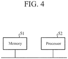
FIG. 4 is a hardware configuration diagram of a computer for a case in which thesignal processor 11 is implemented by using software or firmware. - In the case in which the
signal processor 11 is implemented by using software or firmware, the program for allowing the computer to execute procedures of theFourier transforming unit 22, the spectrumintegration processing unit 23, thenoise removing unit 24, the frequencyshift correcting unit 25, thespectrum integrating unit 26, the peakintensity calculating unit 28, and the molecular concentrationcalculation processing unit 29 may be stored in amemory 51 and aprocessor 52 of the computer may execute the program stored in thememory 51. -
FIGS. 5 and6 are flowcharts illustrating the procedure when thesignal processor 11 is implemented by using software or firmware. - Also,
FIG. 3 illustrates an example in which each of the components of thesignal processor 11 is implemented by the dedicated hardware, andFIG. 4 illustrates an example in which thesignal processor 11 is implemented by using software or firmware; however, some components in thesignal processor 11 may be implemented by the dedicated hardware and remaining components may be implemented by using software or firmware. - The
reference light source 1 outputs the first laser light beam Lb1 to theoptical distributor 3 when receiving the wavelength selecting signal indicating that the first laser light beam Lb1 being the laser light beam of the wavelength absorbed by the molecule in the atmosphere is output from thewavelength selector 2. - The
reference light source 1 also outputs the second laser light beam Lb2 to theoptical distributor 3 when receiving the wavelength selecting signal indicating that the second laser light beam Lb2 being the laser light beam of the wavelength not absorbed by the molecule in the atmosphere is output from thewavelength selector 2. - In
Embodiment 1, it is assumed that thereference light source 1 alternately outputs the first laser light beam Lb1 and the second laser light beam Lb2, but thereference light source 1 may simultaneously output the first laser light beam Lb1 and the second laser light beam Lb2. - When receiving the first laser light beam Lb1 from the
reference light source 1, theoptical distributor 3 distributes the first laser light beam Lb1 to thepulse modulator 4 and theoptical coupler 8 at a predetermined ratio. - When receiving the second laser light beam Lb2 from the
reference light source 1, theoptical distributor 3 distributes the second laser light beam Lb2 to thepulse modulator 4 and theoptical coupler 8 at a predetermined ratio. - When receiving the first laser light beam Lb1 from the
optical distributor 3, thepulse modulator 4 performs pulse modulation of the first laser light beam Lb1. - When receiving the second laser light beam Lb2 from the
optical distributor 3, thepulse modulator 4 performs pulse modulation of the second laser light beam Lb2. - As examples of the pulse modulation of the first laser light beam Lb1 and the second laser light beam Lb2, the
pulse modulator 4 performs intensity modulation of the first laser light beam Lb1 and the second laser light beam Lb2 such that the shapes of the light intensity of the first laser light beam Lb1 and the second laser light beam Lb2 have a Gaussian shape or a rectangular shape. - The
pulse modulator 4 also performs the frequency shift to shift the frequency of the first laser light beam Lb1 and the second laser light beam Lb2 as the pulse modulation of the first laser light beam Lb1 and the second laser light beam Lb2. A frequency shift amount of the first laser light beam Lb1 and the second laser light beam Lb2 is, for example, in a range of 20 MHz to 200 MHz. - As a result, the
pulse modulator 4 outputs the first laser light beam Lb1 and the second laser light beam Lb2 after the pulse modulation to theoptical amplifier 5. - When receiving the first laser light beam Lb1 after the pulse modulation from the
pulse modulator 4, theoptical amplifier 5 amplifies the intensity of the first laser light beam Lb1 after the pulse modulation and outputs the first laser light beam Lb1 after the intensity amplification to theoptical circulator 6. - When receiving the second laser light beam Lb2 after the pulse modulation from the
pulse modulator 4, theoptical amplifier 5 amplifies the intensity of the second laser light beam Lb2 after the pulse modulation and outputs the second laser light beam Lb2 after the intensity amplification to theoptical circulator 6. - When receiving the first laser light beam Lb1 after the intensity amplification from the
optical amplifier 5, theoptical circulator 6 outputs the first laser light beam Lb1 after the intensity amplification to theoptical antenna 7. - When receiving the second laser light beam Lb2 after the intensity amplification from the
optical amplifier 5, theoptical circulator 6 outputs the second laser light beam Lb2 after the intensity amplification to theoptical antenna 7. - When receiving the first laser light beam Lb1 after the intensity amplification from the
optical circulator 6, theoptical antenna 7 expands the beam diameter of the first laser light beam Lb1 after the intensity amplification and emits the first laser light beam Lb1 after the intensity amplification into the atmosphere. - When receiving the second laser light beam Lb2 after the intensity amplification from the
optical circulator 6, theoptical antenna 7 expands the beam diameter of the second laser light beam Lb2 after the intensity amplification and emits the second laser light beam Lb2 after the intensity amplification into the atmosphere. - After emitting the first laser light beam Lb1 after the intensity amplification into the atmosphere, the
optical antenna 7 receives the first scattered light Sb1 being the scattered light of the first laser light beam Lb1 scattered by the aerosol or the hard target in the atmosphere and outputs the first scattered light Sb1 to theoptical circulator 6. - After emitting the second laser light beam Lb2 after the intensity amplification into the atmosphere, the
optical antenna 7 receives the second scattered light Sb2 being the scattered light of the second laser light beam Lb2 scattered by the aerosol or the hard target in the atmosphere and outputs the second scattered light Sb2 to theoptical circulator 6. - When receiving the first scattered light Sb1 from the
optical antenna 7, theoptical circulator 6 outputs the first scattered light Sb1 to theoptical coupler 8, and when receiving the second scattered light Sb2 from theoptical antenna 7, it outputs the second scattered light Sb2 to theoptical coupler 8. - When receiving the first scattered light Sb1 from the
optical circulator 6, theoptical coupler 8 combines the first scattered light Sb1 and the first laser light beam Lb1 output from theoptical distributor 3 and outputs the first combined light beam Cb1 being the combined light beam of the first scattered light Sb1 and the first laser light beam Lb1 to theoptical receiver 9 after branching the same at a ratio of 50 to 50. - When receiving the second scattered light Sb2 from the
optical circulator 6, theoptical coupler 8 combines the second scattered light Sb2 and the second laser light beam Lb2 output from theoptical distributor 3 and outputs the second combined light beam Cb2 being the combined light beam of the second scattered light Sb2 and the second laser light beam Lb2 to theoptical receiver 9 after branching the same at a ratio of 50 to 50. - When receiving two first combined light beams Cb1 branched at a ratio of 50 to 50 from the
optical coupler 8, theoptical receiver 9 performs heterodyne detection on the two first combined light beams Cb1 and outputs the first reception signal R1 being the reception signal of the first combined light beam Cb1 to the A/D converter 10. - When receiving two second combined light beams Cb2 branched at a ratio of 50 to 50 from the
optical coupler 8, theoptical receiver 9 performs heterodyne detection on the two second combined light beam Cb2 and outputs the second reception signal R2 being the reception signal of the second combined light beam Cb2 to the A/D converter 10. - The heterodyne-detection of the first combined light beam Cb1 and the second combined light beam Cb2 by the
optical receiver 9 is balanced detection capable of reducing common mode noise. - Herein,
FIG. 7 is an illustrative view illustrating waveform examples of the first reception signal R1 and the second reception signal R2 output from theoptical receiver 9. -
FIG. 7A illustrates the waveform example of the first reception signal R1, andFIG. 7B illustrates the waveform example of the second reception signal R2. - In
FIG. 7 , time is plotted along the abscissa axis and signal intensity of the reception signal is plotted along the ordinate axis. - In
FIG. 7 , the time range is divided into N and the signal intensity of first to Nth time range bins is illustrated. - When receiving the analog first reception signal R1 and second reception signal R2 from the
optical receiver 9, the A/D converter 10 converts the analog first reception signal R1 and second reception signal R2 to digital signals, and outputs the reception data DR1 and DR2 which are the digital signals to thesignal processor 11. - The
signal processor 11 controls the wavelength selecting signal output from thewavelength selector 2. - In
Embodiment 1, as described above, thesignal processor 11 controls the wavelength selecting signal output from thewavelength selector 2 so that thereference light source 1 alternately outputs the first laser light beam Lb1 and the second laser light beam Lb2. - When receiving the reception data DR1 and DR2 being the digital signals from the A/
D converter 10, thesignal processor 11 calculates the concentration C of the molecules in the atmosphere on the basis of the reception data DR1 and DR2. - Hereinafter, a calculating process of the molecular concentration C by the
signal processor 11 is specifically described. - If the A/
D converter 10 outputs the reception data DR1 (step ST1 inFIG. 5 : YES), then theFourier transforming unit 22 of thesignal processor 11 calculates a plurality of first signal spectra SP1 for each time range as the signals in the frequency domain of the reception data DR1 by performing the FFT on the reception data DR1 (step ST2 inFIG. 5 ). - In addition, when the A/
D converter 10 outputs the reception data DR2 (step ST3 inFIG. 5 : YES), theFourier transforming unit 22 calculates a plurality of second signal spectra SP2 for each time range as the signals in the frequency domain of the reception data DR2 by performing the FFT on the reception data DR2 (step ST4 inFIG. 5 ). - In
Embodiment 1, theFourier transforming unit 22 calculates a plurality of first signal spectra SP1 and a plurality of second signal spectra SP2 in the first to Nth time range bins by performing the FFT on the reception data DR1 and DR2 of the first to Nth time range bins. - Note that, when the reception data DR1 and DR2 are not output from the A/D converter 10 (steps ST1 and ST3 in
FIG. 5 : NO), theFourier transforming unit 22 stands by until the reception data DR1 or DR2 is output from the A/D converter 10. -
FIG. 8 is an illustrative view illustrating an example of calculation of the first signal spectrum SP1 and the second signal spectrum SP2 by theFourier transforming unit 22. -
FIG. 8A illustrates the first signal spectra SP1 of the first time range bin and the second time range bin calculated by theFourier transforming unit 22, andFIG. 8B illustrates the second signal spectra SP2 of the first time range bin and the second time range bin calculated by theFourier transforming unit 22. - In
FIG. 8 , the frequency is plotted along the abscissa axis and the signal intensity is plotted along the ordinate axis. -
FIG. 8 illustrates the example in which there is no change in the position of the aerosol in the atmosphere. - When there is no change in the position of the aerosol in the atmosphere, peak positions being frequencies corresponding to the peak intensities Pon of a plurality of first signal spectra SP1 within the same time range are in the same position. Also, even when the time range is different, as illustrated in
FIG. 8A , the peak positions being the frequencies corresponding to the peak intensities Pon of the first signal spectra SP1 are in the same position. - Also, when there is no change in the position of the aerosol in the atmosphere, the peak positions being frequencies corresponding to the peak intensities Poff of a plurality of second signal spectra SP2 within the same time range are in the same position. Also, even when the time range is different, as illustrated in
FIG. 8B , the peak positions being the frequencies corresponding to the peak intensities Poff of the second signal spectra SP2 are in the same position. - In the examples in
FIGS. 8A and 8B , the peak intensity Pon of the first signal spectrum SP1 and the peak intensity Poff of the second signal spectrum SP2 are all present in a sixth frequency range bin in both the first time range bin and the second time range bin. -
FIG. 9 is an illustrative view illustrating an example of the first signal spectra SP1 and the second signal spectra SP2 calculated by theFourier transforming unit 22 in a situation where the position of the aerosol in the atmosphere is changes due to an influence of wind. - As illustrated in
FIG. 9 , the frequencies corresponding to the peak intensities Pon of a plurality of first signal spectra SP1 within the first time range bin are different, and the frequencies corresponding to the peak intensities Poff of a plurality of second signal spectra SP2 within the first time range bin are different. - That is, the frequency corresponding to the peak intensity Pon of the first signal spectrum SP1(t1) at time t1 in the first time range bin and the frequency corresponding to the peak intensity Pon of the first signal spectrum SP1(t2) at time t2 are different. Also, the frequency corresponding to the peak intensity Poff of the second signal spectrum SP2(t1) at a time t1 in the first time range bin and the frequency corresponding to the peak intensity Poff of the second signal spectrum SP2(t2) at time t2 are different.
- In
FIG. 9 , only the first time range bin is illustrated, but there actually are the second time range bin to the Nth time range bin. N is an integer equal to or larger than three. - When there is no change in the position of the aerosol in the atmosphere, as described above, the peak positions being the frequencies corresponding to the peak intensities of a plurality of first signal spectra SP1 are in the same position. Also, the peak positions being the frequencies corresponding to the peak intensities of a plurality of second signal spectra SP2 are in the same position. Therefore, the spectrum
integration processing unit 23 at a subsequent stage integrates a plurality of first signal spectra SP1 within the same time range and integrates a plurality of second signal spectra SP2 within the same time range, so that signal components corresponding to the aerosol being desired signal components are accumulated and an SN ratio is increased. - On the other hand, when there is a change in the position of the aerosol in the atmosphere, as illustrated in
FIG. 9 , the peak positions being the frequencies corresponding to the peak intensities are different positions even within the same time range. Therefore, even when the spectrumintegration processing unit 23 at the subsequent stage integrates a plurality of first signal spectra SP1 and a plurality of second signal spectra SP2 within the same time range, the desired signal components are not accumulated and the SN ratio is not increased. - Therefore, when there is the change in the position of the aerosol in the atmosphere, it is difficult to improve identification accuracy of the first peak intensity Pon and the second peak intensity Poff by the peak
intensity calculating unit 28 at the subsequent stage even when the spectrumintegration processing unit 23 integrates a plurality of first signal spectra SP1 and a plurality of second signal spectra SP2 within the same time range for a long time (for example, 1 minute or longer). In the example inFIG. 9 , since not only the desired signal component but also a plurality of signal components are increased in the first signal spectrum SP1 after the integration and the second signal spectrum SP2 after the integration, it becomes difficult to identify the first peak intensity Pon and the second peak intensity Poff corresponding to the desired signal component. - However, even when there is a change in the position of the aerosol in the atmosphere, by integrating a plurality of first signal spectra SP1 and a plurality of second signal spectra SP2 for a short time (for example, 4 seconds), an SN ratio is increased to such an extent that the frequency
shift correcting unit 25 at the subsequent stage may calculate frequency shift amounts fd1 and fd2 of the first signal spectrum SP1 and the second signal spectrum SP2. - Since the signal intensity is small only with the signal spectrum of one time range, it is difficult for the frequency
shift correcting unit 25 at the subsequent stage to calculate the frequency shift amount fd1 of the first signal spectrum SP1 and the frequency shift amount fd2 of the second signal spectrum SP2. - If the
Fourier transforming unit 22 calculates a plurality of first signal spectra SP1 for each time range, then the spectrumintegration processing unit 23 integrates a plurality of first signal spectra SP1 within the same time range, and outputs the first signal spectrum SP1 obtained by integration to the noise removing unit 24 (step ST5 inFIG. 5 ) . - Also, if the
Fourier transforming unit 22 calculates a plurality of second signal spectra SP2 for each time range, then the spectrumintegration processing unit 23 integrates a plurality of second signal spectra SP2 within the same time range, and outputs the second signal spectrum SP2 obtained by integration to the noise removing unit 24 (step ST6 inFIG. 5 ). - The integrating process of a plurality of first signal spectra SP1 within the same time range is to integrate the signal components of the same frequency in a plurality of first signal spectra SP1 within the same time range.
- Also, the integrating process of a plurality of second signal spectra SP2 within the same time range is to integrate the signal components of the same frequency in a plurality of second signal spectra SP2 within the same time range.
- The spectrum
integration processing unit 23 repeatedly performs the integrating process of the first signal spectrum SP1 and the second signal spectrum SP2 until the number of times of integration of the first signal spectrum SP1 and the second signal spectrum SP2 reaches the number of times set in advance or until the SN ratio reaches the SN ratio set in advance. - Note that, when the position of the aerosol in the atmosphere changes due to the influence of the wind, even when the spectrum
integration processing unit 23 integrates the signal components of the same frequency, the SN ratio does not significantly increase, but the SN ratio is increased to such an extent that the frequencyshift correcting unit 25 at the subsequent stage may calculate the frequency shift amounts fd1 and fd2. - If the
noise removing unit 24 receives the first signal spectrum SP1 obtained by integration from the spectrumintegration processing unit 23, then it removes noise components included in the integrated first signal spectrum SP1 and outputs the first signal spectrum SP1 obtained by removing the noise components to the frequency shift correcting unit 25 (step ST7 inFig. 5 ). - Also, if the
noise removing unit 24 receives the second signal spectrum SP2 obtained by integration from the spectrumintegration processing unit 23, then it removes the noise components included in the integrated second signal spectrum SP2 and outputs the second signal spectrum SP2 obtained by removing the noise components to the frequency shift correcting unit 25 (step ST8 inFIG. 5 ). -
FIG. 10 is an illustrative view illustrating signal spectra before and after a removing process of noise component is performed by thenoise removing unit 24. -
FIG. 10A illustrates a signal spectrum and a noise spectrum before thenoise removing unit 24 performs a removing process of noise component, andFIG. 10B illustrates a signal spectrum after thenoise removing unit 24 performs a removing process of noise component. - Hereinafter, the removing process of noise component by the
noise removing unit 24 is specifically described. - As illustrated in
FIG. 10A , the first signal spectrum SP1 and the second signal spectrum SP2 before thenoise removing unit 24 performing a removing process of noise component include noise components such as thermal noise of theoptical receiver 9 and amplification light noise emitted from theoptical amplifier 5, in addition to a signal component corresponding to an aerosol which scatters the first laser light beam Lb1 and the second laser light beam Lb2. - Before performing a removing process of noise component, the
noise removing unit 24 observes noise components such as the thermal noise of theoptical receiver 9 and the amplification light noise emitted from theoptical amplifier 5, and records a noise spectrum indicating the noise components. - The
noise removing unit 24 removes the noise components included in the first signal spectrum SP1 by subtracting the recorded noise spectrum from the first signal spectrum SP1 obtained by integration by the spectrumintegration processing unit 23 and outputs the first signal spectrum SP1 as illustrated inFIG. 10B to the frequencyshift correcting unit 25. - Also, the
noise removing unit 24 removes the noise components included in the second signal spectrum SP2 by subtracting the recorded noise spectrum from the second signal spectrum SP2 obtained by integration by the spectrumintegration processing unit 23 and outputs the second signal spectrum SP2 as illustrated inFIG. 10B to the frequencyshift correcting unit 25. - If the frequency
shift correcting unit 25 receives the first signal spectrum SP1 obtained after the noise component removal from thenoise removing unit 24, then it calculates the frequency shift amount fd1 of the first signal spectrum SP1 obtained after the noise component removal with respect to the frequency of the first laser light beam Lb1 emitted from theoptical antenna 7. - The frequency shift amount fd1 corresponds to a Doppler shift amount of the first scattered light Sb1 associated with the change in the position of the aerosol in the atmosphere.
- Since the calculating process of the Doppler shift amount is a well-known technology, this is not described in detail; the Doppler shift amount may be obtained from a difference between the frequency of the first laser light beam Lb1 emitted from the
optical antenna 7 and the frequency of the first scattered light Sb1. - If the frequency
shift correcting unit 25 calculates the frequency shift amount fd1, then it shifts the frequency of the first signal spectrum SP1 obtained after the noise component removal by the shift amount fd1 to correct the frequency of the first signal spectrum SP1 obtained after the noise component removal to have the frequency without Doppler shift (step ST9 inFIG. 5 ). - Also, if the frequency
shift correcting unit 25 receives the second signal spectrum SP2 obtained after the noise component removal from thenoise removing unit 24, then it calculates the frequency shift amount fd2 of the second signal spectrum SP2 obtained after the noise component removal with respect to the frequency of the second laser light beam Lb2 emitted from theoptical antenna 7. The shift amount fd2 may be calculated from a difference between the frequency of the second laser light beam Lb2 emitted from theoptical antenna 7 and the frequency of the second scattered light Sb2. - If the frequency
shift correcting unit 25 calculates the frequency shift amount fd2, then it shifts the frequency of the second signal spectrum SP2 obtained after the noise component removal by the shift amount fd2 to correct the frequency of the second signal spectrum SP2 obtained after the noise component removal to have the frequency without Doppler shift (step ST10 inFIG. 5 ). -
FIG. 11 is an illustrative view illustrating shift correction of the frequency of the signal spectrum by the frequencyshift correcting unit 25. -
FIG. 11 illustrates that the frequencies of first signal spectra SP1 within the same time range are shifted by the frequencyshift correcting unit 25, and the frequencies of second signal spectra SP2 within the same time range are shifted, so that the frequencies of the signal components relating to the aerosol are present in the same frequency range bin. - In the example in
FIG. 11 , the frequency of the signal component corresponding to the aerosol included in a plurality of first signal spectra SP1 after the shift correction is f1. Also, the frequency of the signal component corresponding to the aerosol included in a plurality of second signal spectra SP2 after the shift correction is f2. - In
FIG. 11 , only the first time range bin is illustrated, but there actually are second to Mth time range bins. M is an integer equal to or larger than three. - However, since the integrating process is performed by the spectrum
integration processing unit 23 on the preceding stage, one first signal spectrum SP1 inFIG. 11 is associated with a plurality of first signal spectra SP1 inFIG. 9 . Also, one second signal spectrum SP2 inFIG. 11 is associated with a plurality of second signal spectra SP2 inFIG. 9 . - For example, in a case in which the number of times of integration of the first signal spectrum SP1 and the second signal spectrum SP2 by the spectrum
integration processing unit 23 is five, a first signal spectrum SP1(t1) inFIG. 11 corresponds to first signal spectra SP1(t1) to SP1(t5) at five timings t = 1 to 5 in the same time range inFIG. 9 , and a second signal spectrum SP2(t1) inFIG. 11 correspond to second signal spectra SP2(t1) to SP2(t5) at five timings t = 1 to 5 within the same time range inFIG. 9 . - Similarly, a first signal spectrum SP1(t2) in
FIG. 11 corresponds to first signal spectra SP(t6) to SP1(t10)1 at five timings t = 6 to 10 within the same time range inFIG. 9 . A second signal spectrum SP2(t2) inFIG. 11 corresponds to second signal spectra SP2(t6) to SP2(t10) at five timings t=6 to 10 within the same time range inFIG. 9 . - Herein, an example in which the frequency
shift correcting unit 25 corrects to allow the frequency of the first signal spectrum SP1 to coincide with the frequency of the first laser light beam Lb1, and corrects to allow the frequency of the second signal spectrum SP2 to coincide with the frequency of the second laser light beam Lb2. - A method of correcting the frequencies of the first signal spectrum SP1 and the second signal spectrum SP2 is not limited to the above-described example.
- For example, it is also possible that the frequency
shift correcting unit 25 corrects the frequencies of a plurality of first signal spectra SP1 so that the frequencies of a plurality of first signal spectra SP1 within the same time range have the same Doppler shift amount. Also, it is possible that the frequencyshift correcting unit 25 corrects the frequencies of a plurality of second signal spectra SP2 so that the frequencies of a plurality of second signal spectra SP2 within the same time range have the same Doppler shift amount. - Specifically, an example is considered in which the frequency
shift correcting unit 25 corrects the frequencies of a plurality of first signal spectra SP1 within the same time range such that the Doppler shift amounts of a plurality of first signal spectra SP1 within the same time range are the same as the Doppler shift amount of the first signal spectrum SP1 which is the reference within the same time range. For example, the first signal spectrum SP1 at time t1 is conceivable as the first signal spectrum SP1 as the reference within the same time range. - Also, an example is considered in which the frequency
shift correcting unit 25 corrects the frequencies of a plurality of second signal spectra SP2 within the same time range such that the Doppler shift amounts of a plurality of second signal spectra SP2 within the same time range are the same as the Doppler shift amount of the second signal spectrum SP2 which is the reference within the same time range. - The processes at steps ST1 to ST10 are repeatedly executed until the time elapsed since the
signal processor 11 starts processing elapses an observation time set in advance (step ST11: NO). - When the time elapsed since the
signal processor 11 starts processing elapses the observation time (step ST11: YES), the repetition processes at steps ST1 to ST10 are terminated. - Note that, when the frequency shifts of a plurality of first signal spectra SP1 and a plurality of second signal spectra SP2 in the first to M time range bins are corrected by the frequency
shift correcting unit 25 during the observation time, a plurality of first signal spectra SP1 and a plurality of second signal spectra SP2 in the first to Mth time range bins in which the frequency shifts are corrected are stored in thespectrum integrating unit 26. - The
spectrum integrating unit 26 integrates a plurality of stored first signal spectra SP1 within the same time range in the first to Mth time range bins and outputs the integrated first signal spectrum SP1 to the peak intensity calculating unit 28 (step ST21 inFIG. 6 ). - Also, the
spectrum integrating unit 26 integrates a plurality of stored second signal spectra SP2 within the same time range and outputs the integrated second signal spectrum SP2 to the peak intensity calculating unit 28 (step ST22 inFIG. 6 ). - The integrating process of a plurality of first signal spectra SP1 within the same time range is to integrate the signal components of the same frequency in each first signal spectrum SP1.
- Also, the integrating process of a plurality of second signal spectra SP2 within the same time range is to integrate the signal components of the same frequency in each second signal spectrum SP2.
- A plurality of first signal spectra SP1 the frequencies of which are shifted by the frequency
shift correcting unit 25 is integrated and a plurality of second signal spectra SP2 the frequencies of which are shifted by the frequencyshift correcting unit 25 is integrated, so that even when there is a change in the position of the aerosol in the atmosphere, the signal components corresponding to the aerosol being the desired signal components are accumulated, and the SN ratio is increased. - The peak
intensity calculating unit 28 compares the respective signal components in the first signal spectrum SP1 obtained by integration by thespectrum integrating unit 26 and identifies the first peak intensity Pon that has the largest signal component (step ST23 inFIG. 6 ) . - Also, the peak
intensity calculating unit 28 compares the respective signal components in the second signal spectrum SP2 obtained by integration by thespectrum integrating unit 26 and identifies the second peak intensity Poff that has the largest signal component (step ST24 inFIG. 6 ). - The molecular concentration
calculation processing unit 29 calculates the concentration C of the molecules in the atmosphere from the first peak intensity Pon identified by the peakintensity calculating unit 28 and the second peak intensity Poff identified by the peakintensity calculating unit 28. - Hereinafter, the calculating process of the molecular concentration C by the molecular concentration
calculation processing unit 29 is specifically described. - First, in a case of performing the calculating process of the molecular concentration C in an mth (m = 2, 3,..., M) time range bin, the molecular concentration
calculation processing unit 29 obtains a peak intensity Pon(m) being the first peak intensity Pon of the mth time range bin and a peak intensity Poff(m) being the second peak intensity Poff of the mth time range bin. - Also, the molecular concentration
calculation processing unit 29 obtains a peak intensity Pon(m-1) being the first peak intensity Pon of an (m-1)th time range bin and a peak intensity Poff(m-1) being the second peak intensity Poff of the (m-1)th time range bin. - Next, in accordance with Equation (1) below, the molecular concentration
calculation processing unit 29 calculates an optical depth OD by using the peak intensity Pon(m) and the peak intensity Poff(m) of the mth time range bin and the peak intensity Pon(m-1) and the peak intensity Poff(m-1) of the (m-1)th time range bin (step ST25 inFIG. 6 ).
- The optical depth OD is a ratio of the peak intensity Pon(m) and the peak intensity Poff(m) in the mth time range bin.
- In Eq. (1), Pon(m)/Poff(m) is multiplied by Poff(m-1)/Pon(m-1) to normalize the optical depth OD.
- Next, in accordance with Equation (2) below, the molecular concentration
calculation processing unit 29 calculates the concentration C of the molecules in the atmosphere by using the optical depth OD, a distance z between the position of the aerosol corresponding to the mth time range bin and theoptical antenna 7, an absorption coefficient kon of the absorption wavelength, and an absorption coefficient koff of the non-absorption wavelength (step ST26 inFIG. 6 ). The absorption coefficient kon and the absorption coefficient koff are known coefficients.
- As is apparent from the above-description, according to
Embodiment 1, the frequencyshift correcting unit 25 which corrects the frequency shift of a plurality of first signal spectra SP1 within the same time range with respect to the frequency of the first laser light beam Lb1 and corrects the frequency shift of a plurality of second signal spectra SP2 within the same time range with respect to the frequency of the second laser light beam Lb2 and thespectrum integrating unit 26 which integrates a plurality of first signal spectra SP1 corrected by the frequencyshift correcting unit 25 and integrates a plurality of second signal spectra SP2 corrected by the frequencyshift correcting unit 25 are provided, and the molecularconcentration calculating unit 27 is configured to calculate the concentration C of the molecules in the atmosphere from the first signal spectrum SP1 integrated by thespectrum integrating unit 26 and the second signal spectrum SP2 integrated by thespectrum integrating unit 26, so that there is an effect of preventing deterioration in calculation accuracy of the molecular concentration C even when there is the change in the position of the aerosol in the atmosphere. - Especially, when improving the accuracy in molecular concentration measurement when the atmosphere molecule is water vapor and the absorption spectrum intensity in the wavelength of 1.5 µm band is small, it is required to measure the peak intensity of the absorption wavelength and the non-absorption wavelength at a high SN ratio to calculate the difference. In this case, it is necessary to integrate for a long time such as several minutes to several tens of minutes, but according to
Embodiment 1, even when the position of the aerosol in the atmosphere changes, there is an effect of preventing deterioration in calculation accuracy of the molecular concentration. - In the above-described
Embodiment 1, the example in which the spectrumintegration processing unit 23 integrates the signal components of the same frequency in a plurality of first signal spectra SP1 and a plurality of second signal spectra SP2 is illustrated as the integrating process of a plurality of first signal spectra SP1 within the same time range and a plurality of second signal spectra SP2 within the same time range. - In
Embodiment 2, an example in which a spectrumintegration processing unit 23 integrates signal components of different frequencies in a plurality of first signal spectra SP1 and a plurality of second signal spectra SP2 is described. - Detailed explanations are as follows.
- Herein, an example in which the number of times of integration of the first signal spectrum SP1 and the second signal spectrum SP2 by the spectrum
integration processing unit 23 is six is described. - A plurality of combinations of frequencies the signal components of which in the first signal spectra SP1 and the second signal spectra SP2 at time t1 to t6 within the same time range are integrated is prepared in advance in the spectrum
integration processing unit 23. - For example, a combination pattern A, a combination pattern B, and a combination pattern C are exemplified as patterns of combinations of the frequencies when integrating the signal spectra at time t1 to t6 within the same time range.
-


-

-

- The spectrum
integration processing unit 23 integrates the first signal spectra SP1 obtained at time t1 to t6 and the second signal spectra SP2 obtained at time t1 to t6 respectively in accordance with the combination pattern A, and integrates the first signal spectra SP1 obtained at time t1 to t6 and the second signal spectra SP2 obtained at time t1 to t6 respectively in accordance with the combination pattern B. - Also, the spectrum
integration processing unit 23 integrates the first signal spectra SP1 obtained at time t1 to t6 and the second signal spectra SP2 obtained at time t1 to t6 respectively in accordance with the combination pattern C. - The spectrum
integration processing unit 23 compares the maximum signal components in the first signal spectra SP1 each integrated in accordance with the combination pattern A, B or C, and selects the first signal spectrum SP1 the maximum signal component of which is the maximum among the three first signal spectra SP1 after the integration. - The spectrum
integration processing unit 23 outputs the selected first signal spectrum SP1 to a peakintensity calculating unit 28 as the integrated first signal spectrum SP1. - Also, the spectrum
integration processing unit 23 compares the maximum signal components in the second signal spectra SP2 each integrated based on the combination pattern A, B or C, and selects the second signal spectrum SP2 the maximum signal component of which is the maximum among the three second signal spectra SP2 after the integration. - The spectrum
integration processing unit 23 outputs the selected second signal spectrum SP2 to the peakintensity calculating unit 28 as the integrated second signal spectrum SP2. - As is apparent from the description above, according to
Embodiment 2, the spectrumintegration processing unit 23 is configured to select any one signal spectrum from the signal spectra after the integration corresponding to a plurality of combinations as the signal spectrum after the integration, so that an SN ratio may be increased further compared with that inEmbodiment 1. - In
Embodiment 1 described above, the example in which the frequencyshift correcting unit 25 corrects the frequency shift of the first signal spectrum SP1 with respect to the frequency of the first laser light beam Lb1 and corrects the frequency shift of the second signal spectrum SP2 with respect to the frequency of the second laser light beam Lb2 is described. - As a result, even when the position of the aerosol in the atmosphere changes, it is possible to prevent deterioration in calculation accuracy of the molecular concentration C.
- However, in an environment in which a wind speed or a wind direction changes in terms of time as in a turbulence flow, a frequency band of a signal component corresponding to aerosol included in a first signal spectrum SP1 and a second signal spectrum SP2 calculated by the
Fourier transforming unit 22 can be brodend. - As the frequency band of the signal component corresponding to the aerosol is broadend, the signal component corresponding to the aerosol might be present in a plurality of frequency range bins, and identification accuracy of a first peak intensity Pon and identification accuracy of a second peak intensity Poff can be deteriorated.
- In
Embodiment 3, an example of preventing deterioration in calculation accuracy of molecular concentration by preventing deterioration in the identification accuracy of the first peak intensity Pon and the identification accuracy of the second peak intensity Poff also in the environment in which the wind speed or the wind direction changes in terms of time is described. - A configuration diagram of a laser radar device according to
Embodiment 3 is the configuration diagram inFIG. 1 , as inEmbodiment 1. -
FIG. 12 is a configuration diagram illustrating asignal processor 11 of the laser radar device according toEmbodiment 3 of the present disclosure. InFIG. 12 , the same reference signs as those inFIG. 2 represent the same or corresponding parts, so that the description thereof is omitted. - A frequency
shift correcting unit 30 is implemented by the frequencyshift correcting circuit 44 illustrated inFIG. 3 , for example, as is the case with the frequencyshift correcting unit 25 inFIG. 2 . - The frequency
shift correcting unit 30 performs a process of correcting a frequency shift of a plurality of first signal spectra SP1 after noise component removal with respect to the frequency of the first laser light beam Lb1 and correcting a frequency shift of a plurality of second signal spectra SP2 after noise component removal with respect to the frequency of the second laser light beam Lb2 as is the case with the frequencyshift correcting unit 25 inFIG. 2 . - However, unlike the frequency
shift correcting unit 25 inFIG. 2 , the frequencyshift correcting unit 30 performs a process of correcting a waveform of the first signal spectrum SP1 and the second signal spectrum SP2 to be described hereinafter before performing the process of correcting the frequency shifts of the first signal spectrum SP1 and the second signal spectrum SP2. The frequencyshift correcting unit 30 performs a correcting process of waveform in which the signal component of the selected frequency is a total sum of the signal components equal to or larger than the threshold Th by selecting any one frequency out of equal to or more than one frequencies having a signal component equal to or larger than a threshold Th in each of the first signal spectrum SP1 and the second signal spectrum SP2 obtained after the noise component removal by anoise removing unit 24 and moving the signal component of the remaining frequency not selected to the selected frequency. - Hereinafter, the correcting process of waveform by the frequency
shift correcting unit 30 is specifically described. -
FIG. 13 is an illustrative view illustrating the shift correction of the frequency of the signal spectrum by the frequencyshift correcting unit 30. -
FIG. 13 representatively illustrates only one first signal spectrum SP1 in each of a first time range bin and a second time range bin. Also, only one second signal spectrum SP2 in each of the first time range bin and the second time range bin is representatively illustrated. - The frequency
shift correcting unit 30 compares the signal component in each of the first signal spectrum SP1 after the noise component removal by thenoise removing unit 24 and the second signal spectrum SP2 after the noise component removal with the threshold Th set in advance and specifies the frequency having the signal component equal to or larger than the threshold Th. A value about half of assumed signal intensity of the signal component corresponding to the aerosol is set in the frequencyshift correcting unit 30 as the threshold Th set in advance. - In the example in
FIG. 13 , as for the first signal spectrum SP1 and the second signal spectrum SP2 in the second time range bin, there is one frequency having the signal component equal to or larger than the threshold Th. Therefore, as for the first signal spectrum SP1 and the second signal spectrum SP2 in the second time range bin, the correcting process of the waveform by the frequencyshift correcting unit 30 is not performed. - On the other hand, as for the first signal spectrum SP1 in the first time range bin, there are four frequencies having the signal component equal to or larger than the threshold Th. Therefore, as for the first signal spectrum SP1 in the first time range bin, the correcting process of the waveform by the frequency
shift correcting unit 30 is performed. - Also, as for the second signal spectrum SP2 in the first time range bin, there are three frequencies having the signal component equal to or larger than the threshold Th. Therefore, as for the second signal spectrum SP2 in the first time range bin, the correcting process of the waveform by the frequency
shift correcting unit 30 is performed. - The frequency
shift correcting unit 30 selects one frequency fc, for example, out of four frequencies fa, fb, fc, and fd having the signal component equal to or larger than the threshold Th in the first signal spectrum SP1 in the first time range bin. - When the frequency
shift correcting unit 30 selects one frequency fc, this makes the signal component of the frequency fc the total sum of the signal components of the four frequencies fa, fb, fc, and fd by moving the signal components of the remaining three frequencies fa, fb, and fd to the frequency fc. - Although the frequency fc is herein selected, this is merely an example, and any one of the frequencies fa, fb, and fd may be selected.
- Also, by selecting the frequency within the range of the frequencies fa to fd and moving the signal components of the four frequencies fa, fb, fc, and fd to the selected frequency, the signal component of the selected frequency may be made the total sum of the signal components of the four frequencies fa, fb, fc, and fd.
- The frequency
shift correcting unit 30 selects one frequency ff, for example, out of the three frequencies fe, ff, and fg having the signal components equal to or larger than the threshold Th in the second signal spectrum SP2 in the first time range bin. - When the frequency
shift correcting unit 30 selects one frequency ff, for example, this makes the signal component of the frequency ff the total sum of the signal components of the three frequencies fe, ff, and fg. by moving the signal components of the remaining two frequencies fe and fg to the frequency ff. - Although the frequency ff is herein selected, this is merely an example, and any one of the frequencies fe and fg may be selected.
- Also, by selecting the frequency within the range of the frequencies fe to fg and moving the signal components of the three frequencies fe, ff, and fg to the selected frequency, the signal component of the selected frequency may be made the total sum of the signal components of the three frequencies fe, ff, and fg.
- As the frequency
shift correcting unit 30 performs the correcting process of the waveform, the signal component corresponding to the aerosol is present only in one frequency range bin, so that the identification accuracy of the first peak intensity Pon and the identification accuracy of the second peak intensity Poff are improved. - After performing the correcting process of the waveform, the frequency
shift correcting unit 30 performs a process of correcting the frequency shift of a plurality of first signal spectra SP1 and correcting the frequency shift of a plurality of second signal spectra SP2 as is the case with the frequencyshift correcting unit 25 inFIG. 2 . - In
Embodiment 3, the deterioration in calculation accuracy of molecular concentration may be prevented because the identification accuracy of the first peak intensity Pon and the identification accuracy of the second peak intensity Poff are improved also in the environment in which the wind speed or the wind direction changes in terms of time as in the turbulence flow. - In
Embodiments 1 to 3 described above, the example in which the molecularconcentration calculating unit 27 calculates the concentration C of the molecules in the atmosphere is illustrated, but inEmbodiment 4, an example in which a molecularconcentration calculating unit 27 obtains a distribution of molecular concentrations C is described. -
FIG. 14 is a configuration diagram illustrating a laser radar device according toEmbodiment 4 of the present disclosure. InFIG. 14 , the same reference signs as those inFIG. 1 represent the same or corresponding parts, so that the description thereof is omitted. - A
direction selector 12 provided with, for example, a mirror and the like is a switching unit which switches a direction in which laser light is emitted from anoptical antenna 7 in accordance with a control signal output from asignal processor 11. -
FIG. 15 is a configuration diagram illustrating thesignal processor 11 of the laser radar device according toEmbodiment 4 of the present disclosure. InFIG. 15 , the same reference signs as those inFIG. 2 represent the same or corresponding parts, so that the description thereof is omitted. - A molecular
concentration calculating unit 31 is provided with a peakintensity calculating unit 28 and a molecular concentrationcalculation processing unit 32. - The molecular
concentration calculating unit 31 performs a process of calculating a concentration C of the molecules in the atmosphere from a first signal spectrum SP1 integrated by aspectrum integrating unit 26 and a second signal spectrum SP2 integrated by thespectrum integrating unit 26 as is the case with the molecularconcentration calculating unit 27 inFIG. 2 . - Unlike the molecular
concentration calculating unit 27 inFIG. 2 , the molecularconcentration calculating unit 31 outputs the control signal indicating that the direction in which the laser light is emitted from theoptical antenna 7 is switched to thedirection selector 12, and calculates the concentration C of the molecules in the atmosphere each time thedirection selector 12 switches the direction in which the laser light is emitted, thereby performing a process of obtaining the distribution of the molecular concentrations C. - The molecular concentration
calculation processing unit 32 is implemented by, for example, a molecularconcentration calculating circuit 47 illustrated inFIG. 3 as is the case with the molecular concentrationcalculation processing unit 29 inFIG. 2 . - The molecular concentration
calculation processing unit 32 performs a process of calculating the concentration C of the molecules in the atmosphere from a first peak intensity Pon calculated by the peakintensity calculating unit 28 and a second peak intensity Poff calculated by the peakintensity calculating unit 28 as is the case with the molecular concentrationcalculation processing unit 29 inFIG. 2 . - Unlike the molecular concentration
calculation processing unit 29 inFIG. 2 , the molecular concentrationcalculation processing unit 32 outputs the control signal indicating that the direction in which the laser light is emitted from theoptical antenna 7 is switched to thedirection selector 12. - The molecular concentration
calculation processing unit 32 also performs a process of obtaining the distribution of the molecular concentrations C by calculating the concentration C of the molecules in the atmosphere each time the direction in which the laser light is emitted is switched by thedirection selector 12. - Since the operations other than that of the
direction selector 12 and the molecular concentrationcalculation processing unit 32 are similar to that in the above-describedEmbodiment 1, only the operations of thedirection selector 12 and the molecular concentrationcalculation processing unit 32 are herein described. - The molecular concentration
calculation processing unit 32 outputs the control signal indicating the direction in which the laser light is emitted from theoptical antenna 7 to thedirection selector 12. - The
direction selector 12 sets the laser light emitted from theoptical antenna 7 in the direction indicated by the control signal output from the molecular concentrationcalculation processing unit 32. - The molecular concentration
calculation processing unit 32 calculates the concentration C of the molecules in the atmosphere from the first peak intensity Pon calculated by the peakintensity calculating unit 28 and the second peak intensity Poff calculated by the peakintensity calculating unit 28 as is the case with the molecular concentrationcalculation processing unit 29 inFIG. 2 . - When calculating the concentration C of the molecules in the atmosphere, the molecular concentration
calculation processing unit 32 outputs the control signal indicating that the direction in which the laser light is emitted from theoptical antenna 7 is switched to thedirection selector 12. - The
direction selector 12 switches the direction in which the laser light is emitted from theoptical antenna 7 in accordance with the control signal output from the molecular concentrationcalculation processing unit 32. - Since the above-described processes are repeatedly performed by the
direction selector 12 and the molecular concentrationcalculation processing unit 32, the molecular concentrationcalculation processing unit 32 calculates the concentration C of the molecules corresponding to a plurality of emitting directions. In this manner, the distribution of the molecular concentrations C in the atmosphere is obtained. - Although it is described in
Embodiments 1 to 4 that thereference light source 1 has the function of outputting the first laser light beam Lb1 and the second laser light beam Lb2, it is also possible to provide a reference light source 1a for outputting first laser light beam Lb1 and a reference light source 1b for outputting second laser light beam Lb2 separately. -
FIG. 16 is a configuration diagram illustrating a laser radar device according toEmbodiment 5 of the present disclosure. InFIG. 16 , the same reference signs as those inFIG. 1 represent the same or corresponding parts, so that the description thereof is omitted. - The reference light source 1a is a light source which outputs the first laser light beam Lb1.
- The reference light source 1b is a light source which outputs the second laser light beam Lb2.
- When receiving a wavelength selecting signal indicating that the first laser light beam Lb1 is to be output from a
wavelength selector 2, an optical switch driver 13 outputs a control signal indicating that the reference light source 1a and anoptical distributor 3 are to be connected to each other to anoptical switch 14. - Also, when receiving a wavelength selecting signal indicating that the second laser light beam Lb2 is to be output from the
wavelength selector 2, the optical switch driver 13 outputs a control signal indicating that the reference light source 1b and theoptical distributor 3 are to be connected to each other to theoptical switch 14. - When receiving the control signal indicating that the reference light source 1a and the
optical distributor 3 are to be connected to each other from the optical switch driver 13, theoptical switch 14 connects the reference light source 1a and theoptical distributor 3. - Also, when receiving the control signal indicating that the reference light source 1b and the
optical distributor 3 are to be connected to each other from the optical switch driver 13, theoptical switch 14 connects the reference light source 1b and theoptical distributor 3. -
FIG. 16 illustrates an example in which the reference light sources 1a and 1b, the optical switch driver 13, and theoptical switch 14 are used in the laser radar device inFIG. 1 , but the reference light sources 1a and 1b, the optical switch driver 13, and theoptical switch 14 may also be used in the laser radar device inFIG. 14 . -
Embodiment 5 is different fromEmbodiments 1 to 4 in that the reference light source 1a which outputs the first laser light beam Lb1 and the reference light source 1b which outputs the second laser light beam Lb2 are provided separately, and the optical switch driver 13 and theoptical switch 14 are used to selectively emit the first laser light beam Lb1 or the second laser light beam Lb2 into the atmosphere. - In other points, this is similar to
Embodiments 1 to 4, so that detailed description is omitted. - In
Embodiment 5 also, as inEmbodiment 1, there is an effect that it is possible to prevent deterioration in calculation accuracy of molecular concentration C even when a position of aerosol in the atmosphere changes. - Note that, embodiments may be freely combined, modifications to any components of the embodiments may be freely made, or omissions of any components may be made, within the scope of the invention.
- One or more embodiments of the present disclosure are suitable for a laser radar device for calculating a concentration of molecules in the atmosphere.
-
- 1, 1a, 1b Reference light source
- 2 Wavelength selector
- 3 Optical distributor
- 4 Pulse modulator
- 5 Optical amplifier
- 6 Optical circulator
- 7 Optical antenna
- 8 Optical coupler
- 9 Light receiver
- 10 A/D converter
- 11 Signal processing unit
- 12 Direction selector
- 13 Optical switch driver
- 14 Optical switch
- 21 Spectrum calculating unit
- 22 Fourier transforming unit
- 23 Spectrum integration processing unit
- 24 Noise removing unit
- 25, 30 Frequency shift correcting unit
- 26 Spectrum integrating unit
- 27, 31 Molecular
concentration calculating unit 28 Peak intensity calculating unit - 29, 32 Molecular concentration calculation processing unit
- 41 Fourier transforming circuit
- 42 Spectrum integrating circuit
- 43 Noise removing circuit
- 44 Frequency shift correcting circuit
- 45 Spectrum integrating circuit
- 46 Peak intensity calculating circuit
- 47 Molecular concentration calculating circuit
- 51 Memory
- 52 Processor
Claims (10)
- A laser radar device comprising:a spectrum calculating unit for calculating, as signal spectra of a first combined light beam that is a combined light beam of first scattered light of a first laser light beam with a wavelength absorbed by a molecule in an atmosphere scattered by a scattering body in the atmosphere and the first laser light beam, a plurality of first signal spectra in a same time range, and calculating, as signal spectra of a second combined light beam that is a combined light beam of second scattered light of a second laser light beam with a wavelength not absorbed by the molecule scattered by the scattering body and the second laser light beam, a plurality of second signal spectra in the same time range;a frequency shift correcting unit for correcting a frequency shift of the plurality of first signal spectra with respect to a frequency of the first laser light beam and correcting a frequency shift of the plurality of second signal spectra with respect to a frequency of the second laser light beam;a spectrum integrating unit for integrating the plurality of first signal spectra corrected by the frequency shift correcting unit and integrating the plurality of second signal spectra corrected by the frequency shift correcting unit; anda molecular concentration calculating unit for calculating a concentration of molecules in the atmosphere from the first and second signal spectra integrated by the spectrum integrating unit.
- The laser radar device according to claim 1, wherein the spectrum calculating unit comprises:a Fourier transforming unit for calculating a plurality of first signal spectra per time range for a first reception signal by performing Fourier transform on the first reception signal being a reception signal of the first combined light beam from an optical receiver for detecting the first combined light beam and the second combined light beam, and calculating a plurality of second signal spectra per time range for a second reception signal by performing Fourier transform on the second reception signal being a reception signal of the second combined light beam from the optical receiver; anda spectrum integration processing unit for integrating a plurality of first signal spectra in a same time range calculated by the Fourier transforming unit and integrating a plurality of second signal spectra in the same time range calculated by the Fourier transforming unit, and whereinthe frequency shift correcting unit corrects a frequency shift of a first signal spectrum integrated by the spectrum integration processing unit with respect to the frequency of the first laser light beam and corrects a frequency shift of a second signal spectrum integrated by the spectrum integration processing unit with respect to the frequency of the second laser light beam.
- The laser radar device according to claim 2, wherein the spectrum calculating unit comprises a noise removing unit for removing noise component included in the first signal spectrum integrated by the spectrum integration processing unit to output the first signal spectrum after noise component removal to the frequency shift correcting unit, and removing noise component included in the second signal spectrum integrated by the spectrum integration processing unit to output the second signal spectrum after noise component removal to the frequency shift correcting unit.
- The laser radar device according to claim 2, wherein the spectrum integration processing unit integrates the plurality of first signal spectra by integrating signal components of the same frequency in the plurality of first signal spectra within the same time range calculated by the Fourier transforming unit and integrates the plurality of second signal spectra by integrating signal components of the same frequency in the plurality of second signal spectra within the same time range calculated by the Fourier transforming unit.
- The laser radar device according to claim 2, wherein a plurality of combinations of frequencies for integrating signal components of a plurality of signal spectra is prepared, and
the spectrum integration processing unit integrates signal components of the frequencies indicated by each combination in the plurality of first signal spectra within the same time range calculated by the Fourier transforming unit for each prepared combination of the frequencies and selects any one signal spectrum out of the signal spectra after the integration corresponding to a plurality of combinations as the first signal spectrum after the integration, and integrates the signal components of the frequencies indicated by each combination in the plurality of second signal spectra within the same time range calculated by the Fourier transforming unit for each prepared combination of the frequencies and selects any one signal spectrum out of the signal spectra after the integration corresponding to a plurality of combinations as the second signal spectrum after the integration. - The laser radar device according to claim 1, wherein the molecular concentration calculating unit comprises:a peak intensity calculating unit for calculating a first peak intensity which is a peak intensity of the first signal spectrum integrated by the spectrum integrating unit and calculating a second peak intensity which is a peak intensity of the second signal spectrum integrated by the spectrum integrating unit; anda molecular concentration calculation processing unit for calculating a concentration of the molecules in the atmosphere from the first peak intensity calculated by the peak intensity calculating unit and the second peak intensity calculated by the peak intensity calculating unit.
- The laser radar device according to claim 6, wherein the molecular concentration calculation processing unit calculates a ratio between the first peak intensity calculated by the peak intensity calculating unit and the second peak intensity calculated by the peak intensity calculating unit, and calculates the concentration of the molecules in the atmosphere from the ratio between the first peak intensity and the second peak intensity.
- The laser radar device according to claim 1, wherein the frequency shift correcting unit performs, before correcting the frequency shift of the first and second signal spectra, a correcting process of selecting any one frequency out of one or more frequencies having a signal component equal to or larger than a threshold in the first and second signal spectra, moving a signal component of the frequency not selected to the selected frequency, and then treating a signal component of the selected frequency as a total sum of signal components of the one or more frequencies.
- The laser radar device according to claim 1, comprising:a light source for outputting the first laser light beam and the second laser light beam;an optical antenna for emitting the first laser light beam and the second laser light beam output from the light source into the atmosphere and receiving first scattered light and second scattered light being scattered light of the first and second laser light beams scattered by the scattering body;an optical coupler for combining the first scattered light received by the optical antenna and the first laser light beam to output first combined light beam being combined light beam of the first scattered light and the first laser light beam, and combining the second scattered light received by the optical antenna and the second laser light beam to output second combined light beam being combined light beam of the second scattered light and the second laser light beam; andan optical receiver for detecting the first combined light beam output from the optical coupler to output the first combined light beam to the spectrum calculating unit, and detecting the second combined light beam output from the optical coupler to output the second combined light beam to the spectrum calculating unit.
- The laser radar device according to claim 9, further comprising a direction selector for selecting a direction in which the first laser light beam and the second laser light beam are emitted from the optical antenna, wherein
the molecular concentration calculating unit obtains a distribution of molecular concentrations by calculating the concentration of the molecules in the atmosphere each time the direction selector selects the direction in which the first laser light beam and the second laser light beam are emitted.
Applications Claiming Priority (1)
| Application Number | Priority Date | Filing Date | Title |
|---|---|---|---|
| PCT/JP2017/002282 WO2018138766A1 (en) | 2017-01-24 | 2017-01-24 | Laser radar device |
Publications (3)
| Publication Number | Publication Date |
|---|---|
| EP3564652A1 true EP3564652A1 (en) | 2019-11-06 |
| EP3564652A4 EP3564652A4 (en) | 2020-01-01 |
| EP3564652B1 EP3564652B1 (en) | 2021-09-01 |
Family
ID=62978123
Family Applications (1)
| Application Number | Title | Priority Date | Filing Date |
|---|---|---|---|
| EP17894031.8A Active EP3564652B1 (en) | 2017-01-24 | 2017-01-24 | Laser radar device |
Country Status (5)
| Country | Link |
|---|---|
| US (1) | US11543524B2 (en) |
| EP (1) | EP3564652B1 (en) |
| JP (1) | JP6505343B2 (en) |
| CN (1) | CN110234979B (en) |
| WO (1) | WO2018138766A1 (en) |
Cited By (1)
| Publication number | Priority date | Publication date | Assignee | Title |
|---|---|---|---|---|
| EP4283341A4 (en) * | 2021-02-26 | 2024-03-06 | Mitsubishi Electric Corp | Lidar device |
Families Citing this family (4)
| Publication number | Priority date | Publication date | Assignee | Title |
|---|---|---|---|---|
| US11112502B2 (en) * | 2016-04-05 | 2021-09-07 | Mitsubishi Electric Corporation | Laser radar system |
| CN116848434A (en) * | 2021-02-26 | 2023-10-03 | 三菱电机株式会社 | Signal processing device, signal processing method, and laser radar device |
| JP7034398B1 (en) * | 2021-06-30 | 2022-03-11 | 三菱電機株式会社 | Laser radar device |
| DE102021121211A1 (en) * | 2021-08-16 | 2023-02-16 | OSRAM Opto Semiconductors Gesellschaft mit beschränkter Haftung | Laser distance measuring system and distance measuring method |
Family Cites Families (15)
| Publication number | Priority date | Publication date | Assignee | Title |
|---|---|---|---|---|
| JPH1183629A (en) * | 1997-09-02 | 1999-03-26 | Sumitomo Heavy Ind Ltd | Differential absorption lidar-measuring apparatus |
| GB0411097D0 (en) * | 2004-05-19 | 2004-06-23 | Qinetiq Ltd | Laser radar device and method |
| GB0515605D0 (en) | 2005-07-29 | 2005-09-07 | Qinetiq Ltd | Laser measurement device and method |
| US7260507B2 (en) * | 2005-09-09 | 2007-08-21 | Itt Manufacturing Enterprises, Inc. | Method for improving the performance accuracy in differential absorption lidar for oil and gas pipeline leak detection and quantification |
| CN102288973B (en) * | 2011-06-28 | 2013-03-20 | 华中科技大学 | Multi-meteorological-parameter synchronous measuring method based on spectrum characteristic signals and laser radar |
| JP5881099B2 (en) | 2011-10-06 | 2016-03-09 | 国立研究開発法人宇宙航空研究開発機構 | Colored noise reduction method and device for optical remote airflow measurement device |
| JP5738436B2 (en) * | 2011-12-21 | 2015-06-24 | 三菱電機株式会社 | Laser radar equipment |
| CN104541181B (en) | 2012-08-08 | 2017-05-10 | 三菱电机株式会社 | Radar device |
| JP5984944B2 (en) | 2012-09-14 | 2016-09-06 | 三菱電機株式会社 | Laser radar apparatus and speed calculation method for measurement object |
| JP5855262B2 (en) * | 2012-09-24 | 2016-02-09 | 三菱電機株式会社 | Coherent rider device and laser radar device |
| CN103852595B (en) * | 2012-12-07 | 2016-06-29 | 中国电子科技集团公司第三研究所 | A kind of method of Low level wind detection |
| US8541744B1 (en) * | 2013-03-09 | 2013-09-24 | Jian Liu | Method and apparatus for wavelength locking free optical frequency comb based differential absorption Lidar |
| CN103472255B (en) * | 2013-09-16 | 2017-01-18 | 南京牧镭激光科技有限公司 | Full-optical-fiber Doppler coherent laser radar wind speed measuring device |
| JP6244862B2 (en) * | 2013-12-05 | 2017-12-13 | 三菱電機株式会社 | Laser radar equipment |
| WO2015087380A1 (en) * | 2013-12-09 | 2015-06-18 | 三菱電機株式会社 | Laser radar device |
-
2017
- 2017-01-24 EP EP17894031.8A patent/EP3564652B1/en active Active
- 2017-01-24 US US16/471,430 patent/US11543524B2/en active Active
- 2017-01-24 CN CN201780083987.XA patent/CN110234979B/en active Active
- 2017-01-24 WO PCT/JP2017/002282 patent/WO2018138766A1/en unknown
- 2017-01-24 JP JP2018563960A patent/JP6505343B2/en active Active
Cited By (1)
| Publication number | Priority date | Publication date | Assignee | Title |
|---|---|---|---|---|
| EP4283341A4 (en) * | 2021-02-26 | 2024-03-06 | Mitsubishi Electric Corp | Lidar device |
Also Published As
| Publication number | Publication date |
|---|---|
| CN110234979A (en) | 2019-09-13 |
| EP3564652A4 (en) | 2020-01-01 |
| WO2018138766A1 (en) | 2018-08-02 |
| US20200309950A1 (en) | 2020-10-01 |
| CN110234979B (en) | 2022-01-11 |
| JPWO2018138766A1 (en) | 2019-04-25 |
| US11543524B2 (en) | 2023-01-03 |
| JP6505343B2 (en) | 2019-04-24 |
| EP3564652B1 (en) | 2021-09-01 |
Similar Documents
| Publication | Publication Date | Title |
|---|---|---|
| US11543524B2 (en) | Laser radar device | |
| US20190018144A1 (en) | Coherent lidar | |
| US11709229B2 (en) | Laser radar device | |
| EP3683600B1 (en) | Laser radar device | |
| US20070215795A1 (en) | Differential absorption lidar apparatus | |
| US10175346B2 (en) | Laser radar apparatus and wind velocity observation method | |
| US11921186B2 (en) | Radar device, method of detecting failure of radar device, and method of operating radar device | |
| US20110241923A1 (en) | Digital receiver techniques in radar detectors | |
| US9590740B1 (en) | Method and system for robust symmetrical number system photonic direction finding | |
| US8860608B2 (en) | Photonic assisted digital radar system | |
| CN109891263B (en) | Laser radar device | |
| JP2007333518A (en) | Differential absorption lidar device | |
| EP3399334B1 (en) | Object detecting device and sensor device | |
| US20240103150A1 (en) | Laser radar device | |
| EP4246185A1 (en) | Laser radar device and wind measurement method | |
| JP6847325B1 (en) | Coherent rider device | |
| EP4283341A1 (en) | Lidar device | |
| WO2022180760A1 (en) | Lidar device | |
| US20240004072A1 (en) | Distance measuring device, distance measuring method, and program |
Legal Events
| Date | Code | Title | Description |
|---|---|---|---|
| STAA | Information on the status of an ep patent application or granted ep patent |
Free format text: STATUS: THE INTERNATIONAL PUBLICATION HAS BEEN MADE |
|
| PUAI | Public reference made under article 153(3) epc to a published international application that has entered the european phase |
Free format text: ORIGINAL CODE: 0009012 |
|
| STAA | Information on the status of an ep patent application or granted ep patent |
Free format text: STATUS: REQUEST FOR EXAMINATION WAS MADE |
|
| 17P | Request for examination filed |
Effective date: 20190709 |
|
| AK | Designated contracting states |
Kind code of ref document: A1 Designated state(s): AL AT BE BG CH CY CZ DE DK EE ES FI FR GB GR HR HU IE IS IT LI LT LU LV MC MK MT NL NO PL PT RO RS SE SI SK SM TR |
|
| AX | Request for extension of the european patent |
Extension state: BA ME |
|
| A4 | Supplementary search report drawn up and despatched |
Effective date: 20191129 |
|
| RIC1 | Information provided on ipc code assigned before grant |
Ipc: G01N 21/27 20060101ALI20191125BHEP Ipc: G01S 7/486 20060101ALI20191125BHEP Ipc: G01S 17/95 20060101AFI20191125BHEP Ipc: G01S 7/48 20060101ALI20191125BHEP |
|
| DAV | Request for validation of the european patent (deleted) | ||
| DAX | Request for extension of the european patent (deleted) | ||
| STAA | Information on the status of an ep patent application or granted ep patent |
Free format text: STATUS: EXAMINATION IS IN PROGRESS |
|
| 17Q | First examination report despatched |
Effective date: 20200818 |
|
| STAA | Information on the status of an ep patent application or granted ep patent |
Free format text: STATUS: EXAMINATION IS IN PROGRESS |
|
| REG | Reference to a national code |
Ref country code: DE Ref legal event code: R079 Ref document number: 602017045457 Country of ref document: DE Free format text: PREVIOUS MAIN CLASS: G01N0021270000 Ipc: G01S0017950000 |
|
| RIC1 | Information provided on ipc code assigned before grant |
Ipc: G01S 7/48 20060101ALI20210202BHEP Ipc: G01S 7/481 20060101ALI20210202BHEP Ipc: G01S 7/487 20060101ALI20210202BHEP Ipc: G01S 17/95 20060101AFI20210202BHEP Ipc: G01S 7/497 20060101ALI20210202BHEP Ipc: G01S 7/486 20200101ALI20210202BHEP Ipc: G01N 21/27 20060101ALI20210202BHEP |
|
| GRAP | Despatch of communication of intention to grant a patent |
Free format text: ORIGINAL CODE: EPIDOSNIGR1 |
|
| STAA | Information on the status of an ep patent application or granted ep patent |
Free format text: STATUS: GRANT OF PATENT IS INTENDED |
|
| INTG | Intention to grant announced |
Effective date: 20210324 |
|
| GRAS | Grant fee paid |
Free format text: ORIGINAL CODE: EPIDOSNIGR3 |
|
| GRAA | (expected) grant |
Free format text: ORIGINAL CODE: 0009210 |
|
| STAA | Information on the status of an ep patent application or granted ep patent |
Free format text: STATUS: THE PATENT HAS BEEN GRANTED |
|
| AK | Designated contracting states |
Kind code of ref document: B1 Designated state(s): AL AT BE BG CH CY CZ DE DK EE ES FI FR GB GR HR HU IE IS IT LI LT LU LV MC MK MT NL NO PL PT RO RS SE SI SK SM TR |
|
| REG | Reference to a national code |
Ref country code: GB Ref legal event code: FG4D |
|
| REG | Reference to a national code |
Ref country code: CH Ref legal event code: EP Ref country code: AT Ref legal event code: REF Ref document number: 1426793 Country of ref document: AT Kind code of ref document: T Effective date: 20210915 |
|
| REG | Reference to a national code |
Ref country code: DE Ref legal event code: R096 Ref document number: 602017045457 Country of ref document: DE |
|
| REG | Reference to a national code |
Ref country code: IE Ref legal event code: FG4D |
|
| REG | Reference to a national code |
Ref country code: LT Ref legal event code: MG9D |
|
| REG | Reference to a national code |
Ref country code: NL Ref legal event code: MP Effective date: 20210901 |
|
| PG25 | Lapsed in a contracting state [announced via postgrant information from national office to epo] |
Ref country code: LT Free format text: LAPSE BECAUSE OF FAILURE TO SUBMIT A TRANSLATION OF THE DESCRIPTION OR TO PAY THE FEE WITHIN THE PRESCRIBED TIME-LIMIT Effective date: 20210901 Ref country code: BG Free format text: LAPSE BECAUSE OF FAILURE TO SUBMIT A TRANSLATION OF THE DESCRIPTION OR TO PAY THE FEE WITHIN THE PRESCRIBED TIME-LIMIT Effective date: 20211201 Ref country code: NO Free format text: LAPSE BECAUSE OF FAILURE TO SUBMIT A TRANSLATION OF THE DESCRIPTION OR TO PAY THE FEE WITHIN THE PRESCRIBED TIME-LIMIT Effective date: 20211201 Ref country code: RS Free format text: LAPSE BECAUSE OF FAILURE TO SUBMIT A TRANSLATION OF THE DESCRIPTION OR TO PAY THE FEE WITHIN THE PRESCRIBED TIME-LIMIT Effective date: 20210901 Ref country code: SE Free format text: LAPSE BECAUSE OF FAILURE TO SUBMIT A TRANSLATION OF THE DESCRIPTION OR TO PAY THE FEE WITHIN THE PRESCRIBED TIME-LIMIT Effective date: 20210901 Ref country code: FI Free format text: LAPSE BECAUSE OF FAILURE TO SUBMIT A TRANSLATION OF THE DESCRIPTION OR TO PAY THE FEE WITHIN THE PRESCRIBED TIME-LIMIT Effective date: 20210901 Ref country code: ES Free format text: LAPSE BECAUSE OF FAILURE TO SUBMIT A TRANSLATION OF THE DESCRIPTION OR TO PAY THE FEE WITHIN THE PRESCRIBED TIME-LIMIT Effective date: 20210901 Ref country code: HR Free format text: LAPSE BECAUSE OF FAILURE TO SUBMIT A TRANSLATION OF THE DESCRIPTION OR TO PAY THE FEE WITHIN THE PRESCRIBED TIME-LIMIT Effective date: 20210901 |
|
| REG | Reference to a national code |
Ref country code: AT Ref legal event code: MK05 Ref document number: 1426793 Country of ref document: AT Kind code of ref document: T Effective date: 20210901 |
|
| PG25 | Lapsed in a contracting state [announced via postgrant information from national office to epo] |
Ref country code: PL Free format text: LAPSE BECAUSE OF FAILURE TO SUBMIT A TRANSLATION OF THE DESCRIPTION OR TO PAY THE FEE WITHIN THE PRESCRIBED TIME-LIMIT Effective date: 20210901 Ref country code: LV Free format text: LAPSE BECAUSE OF FAILURE TO SUBMIT A TRANSLATION OF THE DESCRIPTION OR TO PAY THE FEE WITHIN THE PRESCRIBED TIME-LIMIT Effective date: 20210901 Ref country code: GR Free format text: LAPSE BECAUSE OF FAILURE TO SUBMIT A TRANSLATION OF THE DESCRIPTION OR TO PAY THE FEE WITHIN THE PRESCRIBED TIME-LIMIT Effective date: 20211202 |
|
| PG25 | Lapsed in a contracting state [announced via postgrant information from national office to epo] |
Ref country code: AT Free format text: LAPSE BECAUSE OF FAILURE TO SUBMIT A TRANSLATION OF THE DESCRIPTION OR TO PAY THE FEE WITHIN THE PRESCRIBED TIME-LIMIT Effective date: 20210901 |
|
| PG25 | Lapsed in a contracting state [announced via postgrant information from national office to epo] |
Ref country code: IS Free format text: LAPSE BECAUSE OF FAILURE TO SUBMIT A TRANSLATION OF THE DESCRIPTION OR TO PAY THE FEE WITHIN THE PRESCRIBED TIME-LIMIT Effective date: 20220101 Ref country code: SM Free format text: LAPSE BECAUSE OF FAILURE TO SUBMIT A TRANSLATION OF THE DESCRIPTION OR TO PAY THE FEE WITHIN THE PRESCRIBED TIME-LIMIT Effective date: 20210901 Ref country code: SK Free format text: LAPSE BECAUSE OF FAILURE TO SUBMIT A TRANSLATION OF THE DESCRIPTION OR TO PAY THE FEE WITHIN THE PRESCRIBED TIME-LIMIT Effective date: 20210901 Ref country code: RO Free format text: LAPSE BECAUSE OF FAILURE TO SUBMIT A TRANSLATION OF THE DESCRIPTION OR TO PAY THE FEE WITHIN THE PRESCRIBED TIME-LIMIT Effective date: 20210901 Ref country code: PT Free format text: LAPSE BECAUSE OF FAILURE TO SUBMIT A TRANSLATION OF THE DESCRIPTION OR TO PAY THE FEE WITHIN THE PRESCRIBED TIME-LIMIT Effective date: 20220103 Ref country code: NL Free format text: LAPSE BECAUSE OF FAILURE TO SUBMIT A TRANSLATION OF THE DESCRIPTION OR TO PAY THE FEE WITHIN THE PRESCRIBED TIME-LIMIT Effective date: 20210901 Ref country code: EE Free format text: LAPSE BECAUSE OF FAILURE TO SUBMIT A TRANSLATION OF THE DESCRIPTION OR TO PAY THE FEE WITHIN THE PRESCRIBED TIME-LIMIT Effective date: 20210901 Ref country code: CZ Free format text: LAPSE BECAUSE OF FAILURE TO SUBMIT A TRANSLATION OF THE DESCRIPTION OR TO PAY THE FEE WITHIN THE PRESCRIBED TIME-LIMIT Effective date: 20210901 Ref country code: AL Free format text: LAPSE BECAUSE OF FAILURE TO SUBMIT A TRANSLATION OF THE DESCRIPTION OR TO PAY THE FEE WITHIN THE PRESCRIBED TIME-LIMIT Effective date: 20210901 |
|
| REG | Reference to a national code |
Ref country code: DE Ref legal event code: R097 Ref document number: 602017045457 Country of ref document: DE |
|
| PLBE | No opposition filed within time limit |
Free format text: ORIGINAL CODE: 0009261 |
|
| STAA | Information on the status of an ep patent application or granted ep patent |
Free format text: STATUS: NO OPPOSITION FILED WITHIN TIME LIMIT |
|
| PG25 | Lapsed in a contracting state [announced via postgrant information from national office to epo] |
Ref country code: IT Free format text: LAPSE BECAUSE OF FAILURE TO SUBMIT A TRANSLATION OF THE DESCRIPTION OR TO PAY THE FEE WITHIN THE PRESCRIBED TIME-LIMIT Effective date: 20210901 Ref country code: DK Free format text: LAPSE BECAUSE OF FAILURE TO SUBMIT A TRANSLATION OF THE DESCRIPTION OR TO PAY THE FEE WITHIN THE PRESCRIBED TIME-LIMIT Effective date: 20210901 |
|
| 26N | No opposition filed |
Effective date: 20220602 |
|
| PG25 | Lapsed in a contracting state [announced via postgrant information from national office to epo] |
Ref country code: SI Free format text: LAPSE BECAUSE OF FAILURE TO SUBMIT A TRANSLATION OF THE DESCRIPTION OR TO PAY THE FEE WITHIN THE PRESCRIBED TIME-LIMIT Effective date: 20210901 Ref country code: MC Free format text: LAPSE BECAUSE OF FAILURE TO SUBMIT A TRANSLATION OF THE DESCRIPTION OR TO PAY THE FEE WITHIN THE PRESCRIBED TIME-LIMIT Effective date: 20210901 |
|
| REG | Reference to a national code |
Ref country code: CH Ref legal event code: PL |
|
| REG | Reference to a national code |
Ref country code: BE Ref legal event code: MM Effective date: 20220131 |
|
| PG25 | Lapsed in a contracting state [announced via postgrant information from national office to epo] |
Ref country code: LU Free format text: LAPSE BECAUSE OF NON-PAYMENT OF DUE FEES Effective date: 20220124 |
|
| PG25 | Lapsed in a contracting state [announced via postgrant information from national office to epo] |
Ref country code: BE Free format text: LAPSE BECAUSE OF NON-PAYMENT OF DUE FEES Effective date: 20220131 |
|
| PG25 | Lapsed in a contracting state [announced via postgrant information from national office to epo] |
Ref country code: LI Free format text: LAPSE BECAUSE OF NON-PAYMENT OF DUE FEES Effective date: 20220131 Ref country code: CH Free format text: LAPSE BECAUSE OF NON-PAYMENT OF DUE FEES Effective date: 20220131 |
|
| PG25 | Lapsed in a contracting state [announced via postgrant information from national office to epo] |
Ref country code: IE Free format text: LAPSE BECAUSE OF NON-PAYMENT OF DUE FEES Effective date: 20220124 |
|
| P01 | Opt-out of the competence of the unified patent court (upc) registered |
Effective date: 20230512 |
|
| PGFP | Annual fee paid to national office [announced via postgrant information from national office to epo] |
Ref country code: GB Payment date: 20231130 Year of fee payment: 8 |
|
| PGFP | Annual fee paid to national office [announced via postgrant information from national office to epo] |
Ref country code: FR Payment date: 20231212 Year of fee payment: 8 |
|
| REG | Reference to a national code |
Ref country code: DE Ref legal event code: R084 Ref document number: 602017045457 Country of ref document: DE |
|
| PG25 | Lapsed in a contracting state [announced via postgrant information from national office to epo] |
Ref country code: MK Free format text: LAPSE BECAUSE OF FAILURE TO SUBMIT A TRANSLATION OF THE DESCRIPTION OR TO PAY THE FEE WITHIN THE PRESCRIBED TIME-LIMIT Effective date: 20210901 Ref country code: CY Free format text: LAPSE BECAUSE OF FAILURE TO SUBMIT A TRANSLATION OF THE DESCRIPTION OR TO PAY THE FEE WITHIN THE PRESCRIBED TIME-LIMIT Effective date: 20210901 |
|
| PGFP | Annual fee paid to national office [announced via postgrant information from national office to epo] |
Ref country code: DE Payment date: 20231128 Year of fee payment: 8 |