EP3564566A1 - High strength flexible ferrule - Google Patents
High strength flexible ferrule Download PDFInfo
- Publication number
- EP3564566A1 EP3564566A1 EP19174850.8A EP19174850A EP3564566A1 EP 3564566 A1 EP3564566 A1 EP 3564566A1 EP 19174850 A EP19174850 A EP 19174850A EP 3564566 A1 EP3564566 A1 EP 3564566A1
- Authority
- EP
- European Patent Office
- Prior art keywords
- ferrule
- bite
- outer cam
- optionally
- fitting
- Prior art date
- Legal status (The legal status is an assumption and is not a legal conclusion. Google has not performed a legal analysis and makes no representation as to the accuracy of the status listed.)
- Granted
Links
Images






Classifications
-
- F—MECHANICAL ENGINEERING; LIGHTING; HEATING; WEAPONS; BLASTING
- F16—ENGINEERING ELEMENTS AND UNITS; GENERAL MEASURES FOR PRODUCING AND MAINTAINING EFFECTIVE FUNCTIONING OF MACHINES OR INSTALLATIONS; THERMAL INSULATION IN GENERAL
- F16L—PIPES; JOINTS OR FITTINGS FOR PIPES; SUPPORTS FOR PIPES, CABLES OR PROTECTIVE TUBING; MEANS FOR THERMAL INSULATION IN GENERAL
- F16L19/00—Joints in which sealing surfaces are pressed together by means of a member, e.g. a swivel nut, screwed on, or into, one of the joint parts
- F16L19/08—Joints in which sealing surfaces are pressed together by means of a member, e.g. a swivel nut, screwed on, or into, one of the joint parts with metal rings which bite into the wall of the pipe
- F16L19/10—Joints in which sealing surfaces are pressed together by means of a member, e.g. a swivel nut, screwed on, or into, one of the joint parts with metal rings which bite into the wall of the pipe the profile of the ring being altered
-
- F—MECHANICAL ENGINEERING; LIGHTING; HEATING; WEAPONS; BLASTING
- F16—ENGINEERING ELEMENTS AND UNITS; GENERAL MEASURES FOR PRODUCING AND MAINTAINING EFFECTIVE FUNCTIONING OF MACHINES OR INSTALLATIONS; THERMAL INSULATION IN GENERAL
- F16L—PIPES; JOINTS OR FITTINGS FOR PIPES; SUPPORTS FOR PIPES, CABLES OR PROTECTIVE TUBING; MEANS FOR THERMAL INSULATION IN GENERAL
- F16L19/00—Joints in which sealing surfaces are pressed together by means of a member, e.g. a swivel nut, screwed on, or into, one of the joint parts
- F16L19/08—Joints in which sealing surfaces are pressed together by means of a member, e.g. a swivel nut, screwed on, or into, one of the joint parts with metal rings which bite into the wall of the pipe
- F16L19/10—Joints in which sealing surfaces are pressed together by means of a member, e.g. a swivel nut, screwed on, or into, one of the joint parts with metal rings which bite into the wall of the pipe the profile of the ring being altered
- F16L19/103—Joints in which sealing surfaces are pressed together by means of a member, e.g. a swivel nut, screwed on, or into, one of the joint parts with metal rings which bite into the wall of the pipe the profile of the ring being altered with more than one ring per pipe end being used
-
- F—MECHANICAL ENGINEERING; LIGHTING; HEATING; WEAPONS; BLASTING
- F16—ENGINEERING ELEMENTS AND UNITS; GENERAL MEASURES FOR PRODUCING AND MAINTAINING EFFECTIVE FUNCTIONING OF MACHINES OR INSTALLATIONS; THERMAL INSULATION IN GENERAL
- F16L—PIPES; JOINTS OR FITTINGS FOR PIPES; SUPPORTS FOR PIPES, CABLES OR PROTECTIVE TUBING; MEANS FOR THERMAL INSULATION IN GENERAL
- F16L19/00—Joints in which sealing surfaces are pressed together by means of a member, e.g. a swivel nut, screwed on, or into, one of the joint parts
- F16L19/08—Joints in which sealing surfaces are pressed together by means of a member, e.g. a swivel nut, screwed on, or into, one of the joint parts with metal rings which bite into the wall of the pipe
- F16L19/10—Joints in which sealing surfaces are pressed together by means of a member, e.g. a swivel nut, screwed on, or into, one of the joint parts with metal rings which bite into the wall of the pipe the profile of the ring being altered
- F16L19/106—Joints in which sealing surfaces are pressed together by means of a member, e.g. a swivel nut, screwed on, or into, one of the joint parts with metal rings which bite into the wall of the pipe the profile of the ring being altered the ring comprising a shoulder against which the pipe end abuts
Definitions
- the present invention relates generally to tube fittings, and more particularly to high strength flexible ferrule tube fittings.
- exemplary ferrules and ferrule assemblies include features providing advantages compared to conventional ones.
- an exemplary ferrule may be manufactured from stronger materials needed to grip, bite and otherwise hold these stronger tubing materials.
- a ferrule bite edge may be more uniform and less prone to damage providing a more consistent grip and bite of the tubing.
- a ferrule leading edge may more easily slide and bow during assembly to reduce load/torque required to assemble the fitting.
- a ferrule may bow/flex easier at the rear, providing more ferrule spring preload for systems with vibration, impulses, thermo-cycles, etc.
- a ferrule may more easily hinge at the rear to grip the tube and better dampen vibration.
- a ferrule for coupling a tube to a fitting body includes an outer cam surface for bearing against a fitting body or another ferrule; an inner surface defining a central bore extending through a length of a body of the ferrule along a longitudinal direction from a bite edge to a nut end; a recess surface defining a counter bore extending from a bite end to the bite edge, the bite edge thereby recessed from the bite end a distance, X, along the longitudinal direction toward the nut end; wherein a radial distance, A, from the recess surface to the outer cam surface at an axial location of the bite edge (a distance, X from the bite end) is 50% or greater than a radial distance, H, from the inner surface to the recess surface.
- the outer cam surface includes a convex portion and/or one or more flat portions from the bite end to at least about halfway towards the nut end.
- the outer cam surface includes a convex portion along most of the length of the body.
- the outer cam surface includes a plurality of flat portions having respective angles with respect to a longitudinal axis, the respective angles collectively approximating a convex surface.
- the inner surface includes a concave portion.
- X is between 0.5 and 2 times H.
- X is between 1 and ⁇ 3 times H.
- an angle between the bite edge and the inner surface is between 75 and 115 degrees.
- the angle between the bite edge and the inner surface is approximately 90 degrees.
- a fitting assembly for coupling a first tube to a fitting body includes a front ferrule for engagement with the fitting body; and a back ferrule for engagement with a nut, wherein, one of the front ferrule or the back ferrule is a ferrule having any of the features described above.
- the front ferrule is a ferrule having any of the features described above.
- the back ferrule is a ferrule having any of the features described above.
- the back ferrule and the front ferrule are ferrules having any of the features described above.
- the back ferrule includes an outer cam surface having a convex portion and/or one or more flat portions from the bite end to at least about halfway towards the nut end.
- the back ferrule includes an outer cam surface having a convex portion along most of the length of the body.
- the back ferrule includes an outer cam surface having a plurality of flat portions having respective angles with respect to a longitudinal axis, the respective angles collectively approximating a convex surface.
- the back ferrule includes an inner surface having a concave portion.
- a ferrule for coupling a tube to a fitting body includes a body portion having an outer cam surface for bearing against a fitting body or another ferrule and having an inner surface defining a central bore extending through a length of the body portion along a longitudinal direction; and a nose portion having an outer cam surface for bearing against a fitting body or another ferrule and having a recess surface defining a bore extending through a length of the nose portion along the longitudinal direction; wherein an inner diameter of the nose portion is greater than an inner diameter of the body portion, and wherein the outer cam surfaces have respective slopes forming a continuous outer surface, the continuous outer surface being free of an inflection point from at least an outermost axial extent of the nose portion to a position along the body portion from the nose portion equal to an axial length of the nose portion.
- a radial distance, A, from the recess surface to the outer cam surface at an axial location of a bite edge is 50% or greater than a radial distance, H, from the inner surface to the recess surface.
- the outer cam surface includes a convex portion and/or one or more flat portions from the bite end to at least about halfway towards the nut end.
- the outer cam surface includes a convex portion along most of a length of the ferrule.
- the outer cam surface includes a plurality of flat portions having respective angles with respect to a longitudinal axis, the respective angles collectively approximating a convex surface.
- the inner surface includes a concave portion.
- X is between 0.5 and 2 times H.
- X is between 1 and ⁇ 3 times H.
- an angle between the bite edge and the inner surface is between 75 and 115 degrees.
- the angle between the bite edge and the inner surface is approximately 90 degrees.
- a fitting assembly for coupling a first tube to a fitting body includes a front ferrule for engagement with the fitting body; and a back ferrule for engagement with a nut, wherein, one of the front ferrule or the back ferrule is a ferrule having any of the features described above.
- the front ferrule is a ferrule having any of the features described above.
- the back ferrule is a ferrule having any of the features described above.
- the front and the back ferrule are ferrules having any of the features described above.
- the back ferrule includes an outer cam surface having a convex portion and/or one or more flat portions from the bite end to at least about halfway towards the nut end.
- the back ferrule includes an outer cam surface having a convex portion along most of the length of the body.
- the back ferrule includes an outer cam surface having a plurality of flat portions having respective angles with respect to a longitudinal axis, the respective angles collectively approximating a convex surface.
- the back ferrule includes an inner surface having a concave portion.
- a fitting assembly for coupling a first tube to a fitting body includes a ferrule including a reduced thickness portion near a nut end of the ferrule, the reduced thickness portion being thinner than adjacent portions of the ferrule and configured to flex when the fitting assembly is made up; and a nut having a bearing surface for bearing against a bearing surface of the ferrule.
- the ferrule is a ferrule having any of the features described above.
- an angle of the bearing surface of the ferrule is between 3 and 10 degrees different than an angle of the bearing surface of the nut, the angle mismatch thereby causing the reduced thickness portion to flex in a predetermined direction during make up.
- the bearing surface of the ferrule is about 5 degrees more or 5 degrees less than the bearing surface of the nut, the angle mismatch thereby causing the reduced thickness portion to flex in a predetermined direction during make up.
- the bearing surface of the ferrule is about 5 degrees more than the bearing surface of the nut.
- the bearing surface of the ferrule is about 5 degrees more or 5 degrees less than the bearing surface of the nut.
- the ferrule is surface hardened.
- an outer surface of the ferrule is at least 60 Brinell scale points harder than a core of the ferrule.
- the ferrule further includes an undercut between the inner surface and the nose portion.
- the ferrule further includes a radially offset inner surface with a circumference larger than a corresponding inner surface of the ferrule.
- the ferrule further includes a radially offset inner surface longitudinally extending more than 50% of a longitudinal length of the ferrule.
- a conventional tube fitting assembly 10 is illustrated.
- the assembly includes a tube 12 coupled to a fitting body 14 by a nut 16, a front ferrule 20, and a back ferrule 21.
- the fitting body 14 and the nut 16 are threadably engageable with each other, and force the front and back ferrules into mechanical engagement with the tube 12.
- the nut mechanically engages an adjacent end of the back ferrule, pushing the back ferrule against the front ferrule, which is pushed into the body, and down into the tube.
- exemplary ferrules may be surface- or through-hardened by various methods (including, for example, multiple layers of hardness with the respective layers being hardened by the same or by different techniques) and to varying depths or may be non-surface-hardened ferrules.
- exemplary single ferrules and back ferrules are case hardened to ensure uniform bite/grip of the tube. For example a bite depth may be in the range of 0.03 to 0.08 mm (0.001 - 0.003 inches).
- the outer surface of the ferrule may be hardened to more than 60 Brinell scale points harder than a core of the ferrule to more predictability properly engage a bite edge of the ferrule with an outer surface of a tube, in a proper manner, without dulling the bite edge.
- a core of an exemplary ferrule may have a hardness equal to or greater than a tube the ferrule engages with and later hardened.
- the outer 3 to 127 ⁇ m (0.0001 - 0.005 inches) of the outer surface of ferrule may be surface hardened.
- the core may initially have a hardness less than a corresponding tube and the outer layer may be hardened to a hardness greater than the tube to allow the ferrule to cleanly bite into the tube.
- Exemplary hardening techniques include gas infusion methods (for example, nitriding, carbo-nitriding, etc.), hard coatings (for example, carbon and diamond-like coatings, titanium nitride, etc.), mechanical surface hardening (for example, burnishing, etc.), or any other suitable surface hardening method.
- the ferrule may have a hardness greater than HRB 95 or a tensile strength greater than 100 ksi.
- the ferrule may include any suitable material with a sufficient hardness and strength, such as stainless steels and other corrosion resistant alloys.
- the ferrule may include XM-19 and may be surface hardened.
- the ferrule may include austenitic stainless steels and precipitation hardened alloys like 718.
- the assembly includes a tube 112 coupled to a fitting body 114 by a nut 116 and a ferrule 120.
- the ferrule includes a body portion 122 having an outer cam surface 124 for bearing against the fitting body 114.
- the outer cam surface 124 would be configured to bear against a front ferrule.
- the body portion 122 also has an inner surface 126 defining a central bore 128 extending through a length of the body portion along a longitudinal direction from a bite edge 138 to a nut end 129.
- a nose portion 130 includes an outer cam surface 132 for bearing against a fitting body. In a two ferrule embodiment in which the illustrated ferrule 120 is a back ferrule, the outer cam surface 132 would be configured to bear against a front ferrule.
- the nose portion 130 also includes a recess surface 134 defining a bore (also referred to herein as a counterbore) 136 extending through a length of the nose portion 130 along the longitudinal direction from a bite end 137 to the bite edge 138.
- exemplary embodiments of the ferrule are shown at 220, 320, 420, and 520.
- the ferrules 220, and 320, 420, 520 are substantially the same as the above-referenced ferrule 120, and consequently the same reference numerals but indexed by 100 are used to denote structures corresponding to similar structures in the ferrule.
- the foregoing description of the ferrule 120 is equally applicable to the ferrules 220, and 320, 420, 520 except as noted below.
- aspects of the ferrules may be substituted for one another or used in conjunction with one another where applicable.
- the inner diameter of the nose portion 230, 330, 430, 530 is greater than the inner diameter of the body portion, thus providing a recessed biting edge 238, 338, 438, 538-recessed a distance, X, along the longitudinal direction toward the nut end-which bites into a tube after makeup.
- the recessed bite edge better protects the bite edge from accidental damage during the life of the ferrule. In particular, handling damage can occur from numerous sources including but not limited to manufacture, transporting, storage, installation, etc. The further the bite edge is recessed the more it is protected from handling damage. Also, recessing the bite edge makes it easier to collapse the nose of the ferrule by reducing nose material and moving the peak compressive load back from the nose of the ferrule.
- X could be between about 0.5 and 2 times H, it is more preferably between 1 and ⁇ 3 times H.
- the recessed bite edge should also be formed in such a way as to optimize bite in this configuration. Therefore, an angle between the bite edge and the inner surface is between 75 and 115 degrees in exemplary embodiments. In some exemplary embodiments the angle between the bite edge and the inner surface is approximately 90 degrees.
- the height of the recess also needs to be sufficient for the dam of tube material that is created assembling and loading the ferrule 620, 720 to maximum conditions as shown in Fig. 4 .
- the ferrule 620, 720, 820 is substantially the same as the above-referenced ferrules 120, 220, 320, 420, 520 and consequently the same reference numerals but indexed by 100 are used to denote structures corresponding to similar structures in the ferrule.
- the foregoing description of the ferrules 120, 220, 320, 420, 520 is equally applicable to the ferrule 620, 720, 820 except as noted below.
- a thickness or radial distance, A from the recess surface to the outer cam surface at an axial location of the bite edge is preferably 50% or greater than a radial distance, H, from the inner surface to the recess surface. More preferably, A is between about 1 and 2 times the thickness of H.
- this height, H will depend on material types and loading conditions.
- a ferrule 820 may include a nose angle ⁇ that approximately matches a body seat angle both before and after assembly of the ferrule 820.
- Conventional fittings typically have an angled mismatch between the body seat and nose of about 20°, while some are bent to about 12° early in makeup.
- Approximately matching the nose angle ⁇ to the body seat angle reduces bending stress across section T during makeup of the ferrule 820. Reducing bending stress allows higher loads on the ferrule 820.
- the preferable nose thickness T is approximately equal to the thickness of H, for example between 70% - 130% of the thickness of H.
- QSS fittings include a nose thickness T of between 45% - 60% of the thickness of H.
- the nose thickness may be less than 70% or greater than 130%.
- a typical ferrule is shown at 920 and exemplary embodiments of the ferrule are shown at 1020, 1120, 1220, 1320, 1420, 1520, and 1620.
- the ferrules 1020, 1120, 1220, 1320, 1420, 1520, 1620 are substantially the same as the above-referenced ferrules 120, 220, 320, 620, 720, 820 and consequently the same reference numerals but indexed by 100 are used to denote structures corresponding to similar structures in the ferrule.
- ferrule 120, 220, 320, 620, 720, 820 is equally applicable to the ferrules 1020, 1120, 1220, 1320, 1420, 1520, 1620 except as noted below.
- aspects of the ferrules may be substituted for one another or used in conjunction with one another where applicable.
- Fig. 5 shows another exemplary feature: a continuous arc/bow on the outside of the ferrule as compared to a typical ferrule. Therefore, the outer cam surfaces 1024, 1032; 1124, 1132; 1224, 1232; 1324, 1332, 1424, 1432, 1524, 1532, 1624, 1632 may include a convex portion along most of the length of the body. This arc can also be simulated by a variety of tapered surfaces as in ferrule 1320. Thus, the outer cam surfaces may include a plurality of flat portions having respective angles with respect to a longitudinal axis, the respective angles collectively approximating a convex surface.
- Thin sections toward the bite end 1037, 1137, 1237, 1237, 1337, 1437, 1537, 1637 and nut end 1029, 1129, 1229, 1329, 1429, 1529, 1629 of the ferrule encourages the middle of the ferrule to bow radially outwards and the ends to bow radially inwards towards the tube when assembled. This bowing action can be increased for even stronger materials by relieving the inside of the ferrule.
- the inner surface 1026, 1126, 1226, 1326, 1426, 1526, 1626 may include a concave portion as shown in ferrule 1520, 1620. This bowing action improves the spring like action of the ferrule to provide better resistance to thermo-cycling and impulse loads.
- the bowing action at the front also provides more tube grip and bite from the ferrule with less assembly load/torque.
- the bowing action near the back of the ferrule makes it easier to compress on the tubing and improve vibration resistance.
- the concave portion 1542 of ferrule 1520 begins at a bite edge of the ferrule 1520, which increases flexibility of the ferrule 1520.
- the concave portion 1642 of ferrule 1620 begins axially spaced from the bite edge of ferrule 1620 by a front inner surface 1644 to adjust the flexibility of the ferrule 1620.
- the size, shape, and/or location of the concave portion 1626 may be adjusted to modify the bowing action and in turn the flexibility of the ferrule 1620.
- the concave portion is shaped in conjunction with the outer surface of the ferrule so as to provide for the thinnest portion of the ferrule between the outer surface and the concave portion to be toward the leading edge of the ferrule.
- the curve of the outer surface and the concave portion may then, from the thinnest portion, be parallel so as to create a constant thickness ferrule, or be divergent so as to gradually increase the thickness of the ferrule so as to control the springiness of the ferrule and cause it to bend more towards the leading edge.
- An undercut 1145, 1245, 1445 between the inner surface and the nose portion toward the bite end 1137, 1237, 1437 encourages the front and/or middle of the ferrule corresponding to the undercut 1145, 1245, 1445 to bow radially outwards and the front end to bow radially inwards towards the tube when assembled.
- the undercut 1145, 1245, 1445 is defined by a radially offset inner surface 1146, 1246, 1446 that is radially outward from the inner surface 1126, 1226, 1426 and an angled radially inward facing surface 1147, 1247, 1447 extending between the inner surface 1126, 1226, 1426 and the radially offset inner surface 1146, 1246, 1446.
- the undercut 1145, 1245, 1445 and the angled radially inward facing surface 1147, 1247, 1447 may extend both radially and longitudinally between the bite edge 1138, 1238, 1438 and the inner surface to allow the front end of the ferrule 1120, 1220, 1420 to more easily bend radially inward to engage the tube.
- the depth of the offset between the radially offset inner surface and the inner surface is between 0.05 and 0.25 mm (0.002 inches and 0.010 inches) in a radial dimension (the difference in diameter would therefore, be between 0.1 and 0.5 mm (0.004 and 0.020 inches)). In any case, this difference is less than the height H described above.
- Ferrule 1120 includes the undercut 1145 formed by the radially offset inner surface 1146 extends less than 50% a longitudinal length of the ferrule 1120 and allows the corresponding bite end 1137 to collapse easier, allowing use of stronger materials. This allows a user to assemble the ferrule 1124 against stronger materials with less force.
- An angle runout 1148 may be positioned such that it engages with a tube during assembly. This reduces and limits the bite depth of the bite edge 1138 and provides additional tubing grip to isolate the bite from line loads (e.g., vibration, fatigue, impulses, etc.).
- the undercut 1145 may extend to a longitudinal position between the front of ferrule 1120 and a point where a slope of the outer cam surface 1120 becomes negative to facilitate engagement of the tube and the angle runout 1148 during assembly.
- the undercut 1245 extends past a middle portion of the ferrule.
- ferrule 1220, 1420 includes the radially offset inner surface 1246, 1446 that extends longitudinally from the bite edge 1238, 1438 to a position near the back of the ferrule 1220, 1420.
- the radially offset inner surface 1246, 1446 extends past a point where a slope of the outer cam surface 1224, 1424 becomes negative. The additional length of the radially offset inner surface 1246, 1446 allows the bite ends 1237, 1437 of the ferrule 1220, 1420 to collapse easier during assembly and further induces the length of the ferrule 1220, 1420 to bow.
- the inner and outer surfaces may have respectively different curves, thereby controlling the thickness of the ferrule along its length.
- an outer surface having a curve with a larger circumference than the inner surface may produce a thinned middle portion of the ferrule which may promote ferrule flexion. As described, this increased flexion may provide significant benefits including, for example, improved cycling fatigue resistance.
- the outer cam surfaces 1024, 1032; 1124, 1132; 1224, 1232; 1324, 1332, 1424, 1432, 1524, 1532, 1624, 1632 may have respective slopes forming a continuous outer surface 1040, 1140, 1240, 1340, 1440, 1540, 1640 the continuous outer surface 1040, 1140, 1240, 1340, 1440, 1540, 1640 being free of an inflection point from at least an outermost axial extent of the nose portion to a position along the body portion from the nose portion equal to an axial length of the nose portion.
- An inflection point is a point, present in some ferrules, where the change in the slope (the derivative of the slope) changes from positive to negative, or negative to positive.
- exemplary embodiments of the fitting assembly are shown at 1710 and 1810, and include exemplary ferrules 1720 and 1820, respectively.
- the fitting assemblies 1710 and 1810 and ferrules 1720 and 1820 are substantially the same as the above-referenced fitting assemblies and ferrules and consequently the same reference numerals but indexed by 100 are used to denote structures corresponding to similar structures in the ferrule.
- the foregoing description of the fitting assemblies and ferrules is equally applicable to the fitting assemblies 1710 and 1810 and ferrules 1720 and 1820 except as noted below.
- aspects of the ferrules may be substituted for one another or used in conjunction with one another where applicable.
- Fitting assembly 1710 and 1810 includes a ferrule 1720 and 1820 having a reduced thickness portion 1750, 1850 near a nut end of the ferrule, the reduced thickness portion being thinner than adjacent portions of the ferrule and thus allows the ferrule to flex at a known location in a controlled manner when the fitting assembly is made up.
- the fitting assembly 1710 and 1810 also include a nut 1716 and 1816 having a bearing surface 1751 and 1851 for bearing against a bearing surface 1752 and 1852 of the ferrule.
- the bearing surface of the ferrule is 3-10 degrees more or less than the bearing surface of the nut, the angle mismatch thereby causing the reduced thickness portion to flex in a predetermined direction during make up, either radially outward or radially inward.
- the bearing surface of the ferrule is about 5 degrees more or 5 degrees less than the bearing surface of the nut. In either instance, a portion of the rear part of the ferrule compresses into the tube, due to the nut end of the ferrule pivoting about the reduced thickness portion, to better isolate vibration and lines loads from the seals at the front of the ferrule.
- ferrule 7c, 7e, 7g include an undercut portion that allows additional ferrule bow (spring) and improves resistance to line loads and wear resistance during re-assembly of the ferrule 7c, 7e, 7g.
- FIG. 8 various ferrules, back and front, for use in a two ferrule assembly, are shown and configurations "8b" through “8h” incorporate various aspects of the present invention ("8a” shows conventional ferrules). These exemplary ferrules and others may be matched with each other to form various combinations of front and back ferrules in ways as shown and which will, upon reading and understanding the present disclosure, be apparent to those of skill in the art.
- Fig. 9a shows a conventional ferrule without a bite edge engaging an outer wall of a tube
- FIG. 9b shows an exemplary ferrule with a recess surface in a bite end without a bite edge engaging an outer wall of a tube.
- the recess surface of the bite end helps protect the radially inward portion of the nose portion that engages the outer wall of the tube.
- the recess surface separates the radially inward portion from potential damage caused by transporting or assembly of the ferrule.
Landscapes
- Engineering & Computer Science (AREA)
- General Engineering & Computer Science (AREA)
- Mechanical Engineering (AREA)
- Mechanical Coupling Of Light Guides (AREA)
- Joints With Pressure Members (AREA)
- Joints That Cut Off Fluids, And Hose Joints (AREA)
Abstract
Description
- The present invention relates generally to tube fittings, and more particularly to high strength flexible ferrule tube fittings.
- As tubing materials become stronger and harder for higher pressure applications, the ferrule materials have also become much stronger in order to grip, bite and hold the stronger tubing material. As a result, the forces and torques required to assemble these fittings are increasingly making proper assembly more difficult.
- Therefore, exemplary ferrules and ferrule assemblies include features providing advantages compared to conventional ones. For example, an exemplary ferrule may be manufactured from stronger materials needed to grip, bite and otherwise hold these stronger tubing materials. A ferrule bite edge may be more uniform and less prone to damage providing a more consistent grip and bite of the tubing. A ferrule leading edge may more easily slide and bow during assembly to reduce load/torque required to assemble the fitting. A ferrule may bow/flex easier at the rear, providing more ferrule spring preload for systems with vibration, impulses, thermo-cycles, etc. A ferrule may more easily hinge at the rear to grip the tube and better dampen vibration.
- According to one aspect of the invention, a ferrule for coupling a tube to a fitting body includes an outer cam surface for bearing against a fitting body or another ferrule; an inner surface defining a central bore extending through a length of a body of the ferrule along a longitudinal direction from a bite edge to a nut end; a recess surface defining a counter bore extending from a bite end to the bite edge, the bite edge thereby recessed from the bite end a distance, X, along the longitudinal direction toward the nut end; wherein a radial distance, A, from the recess surface to the outer cam surface at an axial location of the bite edge (a distance, X from the bite end) is 50% or greater than a radial distance, H, from the inner surface to the recess surface.
- Optionally, the outer cam surface includes a convex portion and/or one or more flat portions from the bite end to at least about halfway towards the nut end.
- Optionally, the outer cam surface includes a convex portion along most of the length of the body.
- Optionally, the outer cam surface includes a plurality of flat portions having respective angles with respect to a longitudinal axis, the respective angles collectively approximating a convex surface.
- Optionally, the inner surface includes a concave portion.
- Optionally, X is between 0.5 and 2 times H.
- Optionally, X is between 1 and √3 times H.
- Optionally, an angle between the bite edge and the inner surface is between 75 and 115 degrees.
- Optionally, the angle between the bite edge and the inner surface is approximately 90 degrees.
- According to another aspect of the invention, a fitting assembly for coupling a first tube to a fitting body includes a front ferrule for engagement with the fitting body; and
a back ferrule for engagement with a nut, wherein, one of the front ferrule or the back ferrule is a ferrule having any of the features described above. - Optionally, the front ferrule is a ferrule having any of the features described above.
- Optionally, the back ferrule is a ferrule having any of the features described above.
- Optionally, the back ferrule and the front ferrule are ferrules having any of the features described above.
- Optionally, the back ferrule includes an outer cam surface having a convex portion and/or one or more flat portions from the bite end to at least about halfway towards the nut end.
- Optionally, the back ferrule includes an outer cam surface having a convex portion along most of the length of the body.
- Optionally, the back ferrule includes an outer cam surface having a plurality of flat portions having respective angles with respect to a longitudinal axis, the respective angles collectively approximating a convex surface.
- Optionally, the back ferrule includes an inner surface having a concave portion.
- According to another aspect of the invention, a ferrule for coupling a tube to a fitting body includes a body portion having an outer cam surface for bearing against a fitting body or another ferrule and having an inner surface defining a central bore extending through a length of the body portion along a longitudinal direction; and a nose portion having an outer cam surface for bearing against a fitting body or another ferrule and having a recess surface defining a bore extending through a length of the nose portion along the longitudinal direction; wherein an inner diameter of the nose portion is greater than an inner diameter of the body portion, and wherein the outer cam surfaces have respective slopes forming a continuous outer surface, the continuous outer surface being free of an inflection point from at least an outermost axial extent of the nose portion to a position along the body portion from the nose portion equal to an axial length of the nose portion.
- Optionally, a radial distance, A, from the recess surface to the outer cam surface at an axial location of a bite edge is 50% or greater than a radial distance, H, from the inner surface to the recess surface.
- Optionally, the outer cam surface includes a convex portion and/or one or more flat portions from the bite end to at least about halfway towards the nut end.
- Optionally, the outer cam surface includes a convex portion along most of a length of the ferrule.
- Optionally, the outer cam surface includes a plurality of flat portions having respective angles with respect to a longitudinal axis, the respective angles collectively approximating a convex surface.
- Optionally, the inner surface includes a concave portion.
- Optionally, X is between 0.5 and 2 times H.
- Optionally, X is between 1 and √3 times H.
- Optionally, an angle between the bite edge and the inner surface is between 75 and 115 degrees.
- Optionally, the angle between the bite edge and the inner surface is approximately 90 degrees.
- According to another aspect of the invention, a fitting assembly for coupling a first tube to a fitting body includes a front ferrule for engagement with the fitting body; and a back ferrule for engagement with a nut, wherein, one of the front ferrule or the back ferrule is a ferrule having any of the features described above.
- Optionally, the front ferrule is a ferrule having any of the features described above.
- Optionally, the back ferrule is a ferrule having any of the features described above.
- Optionally, the front and the back ferrule are ferrules having any of the features described above.
- Optionally, the back ferrule includes an outer cam surface having a convex portion and/or one or more flat portions from the bite end to at least about halfway towards the nut end.
- Optionally, the back ferrule includes an outer cam surface having a convex portion along most of the length of the body.
- Optionally, the back ferrule includes an outer cam surface having a plurality of flat portions having respective angles with respect to a longitudinal axis, the respective angles collectively approximating a convex surface.
- Optionally, the back ferrule includes an inner surface having a concave portion.
- According to another aspect of the present invention, a fitting assembly for coupling a first tube to a fitting body, includes a ferrule including a reduced thickness portion near a nut end of the ferrule, the reduced thickness portion being thinner than adjacent portions of the ferrule and configured to flex when the fitting assembly is made up; and a nut having a bearing surface for bearing against a bearing surface of the ferrule.
- Optionally, the ferrule is a ferrule having any of the features described above.
- Optionally, an angle of the bearing surface of the ferrule is between 3 and 10 degrees different than an angle of the bearing surface of the nut, the angle mismatch thereby causing the reduced thickness portion to flex in a predetermined direction during make up.
- Optionally, the bearing surface of the ferrule is about 5 degrees more or 5 degrees less than the bearing surface of the nut, the angle mismatch thereby causing the reduced thickness portion to flex in a predetermined direction during make up.
- Optionally, the bearing surface of the ferrule is about 5 degrees more than the bearing surface of the nut.
- Optionally, the bearing surface of the ferrule is about 5 degrees more or 5 degrees less than the bearing surface of the nut.
- Optionally, the ferrule is surface hardened.
- Optionally, an outer surface of the ferrule is at least 60 Brinell scale points harder than a core of the ferrule.
- Optionally, the ferrule further includes an undercut between the inner surface and the nose portion.
- Optionally, the ferrule further includes a radially offset inner surface with a circumference larger than a corresponding inner surface of the ferrule.
- Optionally, the ferrule further includes a radially offset inner surface longitudinally extending more than 50% of a longitudinal length of the ferrule.
- The foregoing and other features of the invention are hereinafter described in greater detail with reference to the accompanying drawings.
-
-
FIG. 1 shows a top-half cross-sectional view of a conventional two-ferrule tube fitting assembly; -
FIG. 2 shows a top-half cross-sectional view of an exemplary single ferrule compression fitting having a recessed bite edge; -
FIG. 3 shows a partial cross-sectional view of two exemplary ferrules each having a recessed bite edge; -
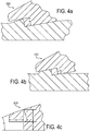
FIG. 4 shows a partial cross-sectional view of two tube fitting assemblies each having a recessed bite edge, the top view showing a well-proportioned bite-height, the bottom view showing a shallow bite-height; -
FIG. 5 shows a top-half cross-sectional view of seven exemplary ferrules having curved surfaces; -
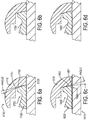
FIG. 6 shows partial cross-sectional views of two exemplary tube fitting assemblies having mismatched bearing surfaces before and after makeup. -
FIG. 7 shows top-half cross-sectional views of several illustrative examples of back and front ferrules, some exemplary, some conventional, which can be employed in an exemplary tube fitting assembly by mixing conventional ferrules with exemplary ferrules or by using only exemplary ferrules. -
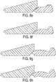
FIG. 8 shows top-half cross-sectional views of several illustrative examples of mixing conventional ferrules with exemplary ferrules and only exemplary ferrules. -
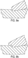
FIG. 9 shows top-half cross-sectional views of an exemplary ferrule engaging an outer surface of a tube with a recess surface and without a bite edge. - Referring to
Fig. 1 , a conventional tubefitting assembly 10 is illustrated. The assembly includes atube 12 coupled to afitting body 14 by anut 16, afront ferrule 20, and aback ferrule 21. Thefitting body 14 and thenut 16 are threadably engageable with each other, and force the front and back ferrules into mechanical engagement with thetube 12. In particular, as the nut is tightened on the body, the nut mechanically engages an adjacent end of the back ferrule, pushing the back ferrule against the front ferrule, which is pushed into the body, and down into the tube. - Throughout this application, both one and two ferrule assemblies are described. It is contemplated that, unless otherwise stated, aspects of the present invention may be applicable to either one or two ferrule assemblies. In two ferrule assemblies, either of the front or back ferrule or both the front and back ferrule may include one or more features described herein. Further, exemplary ferrules may be surface- or through-hardened by various methods (including, for example, multiple layers of hardness with the respective layers being hardened by the same or by different techniques) and to varying depths or may be non-surface-hardened ferrules. In some exemplary fitting assemblies for example, exemplary single ferrules and back ferrules are case hardened to ensure uniform bite/grip of the tube. For example a bite depth may be in the range of 0.03 to 0.08 mm (0.001 - 0.003 inches).
- In an embodiment the outer surface of the ferrule may be hardened to more than 60 Brinell scale points harder than a core of the ferrule to more predictability properly engage a bite edge of the ferrule with an outer surface of a tube, in a proper manner, without dulling the bite edge. For example, a core of an exemplary ferrule may have a hardness equal to or greater than a tube the ferrule engages with and later hardened. The outer 3 to 127 µm (0.0001 - 0.005 inches) of the outer surface of ferrule may be surface hardened. Alternatively, the core may initially have a hardness less than a corresponding tube and the outer layer may be hardened to a hardness greater than the tube to allow the ferrule to cleanly bite into the tube.
- Exemplary hardening techniques include gas infusion methods (for example, nitriding, carbo-nitriding, etc.), hard coatings (for example, carbon and diamond-like coatings, titanium nitride, etc.), mechanical surface hardening (for example, burnishing, etc.), or any other suitable surface hardening method. The ferrule may have a hardness greater than HRB 95 or a tensile strength greater than 100 ksi. The ferrule may include any suitable material with a sufficient hardness and strength, such as stainless steels and other corrosion resistant alloys. For example, the ferrule may include XM-19 and may be surface hardened. Alternatively, the ferrule may include austenitic stainless steels and precipitation hardened alloys like 718.
- Referring now to
Fig. 2 , an exemplary tubefitting assembly 100 is illustrated. The assembly includes atube 112 coupled to afitting body 114 by anut 116 and aferrule 120. - The ferrule includes a
body portion 122 having anouter cam surface 124 for bearing against thefitting body 114. In a two ferrule embodiment in which the illustratedferrule 120 is a back ferrule, theouter cam surface 124 would be configured to bear against a front ferrule. Thebody portion 122 also has aninner surface 126 defining acentral bore 128 extending through a length of the body portion along a longitudinal direction from abite edge 138 to anut end 129. - A
nose portion 130 includes anouter cam surface 132 for bearing against a fitting body. In a two ferrule embodiment in which the illustratedferrule 120 is a back ferrule, theouter cam surface 132 would be configured to bear against a front ferrule. Thenose portion 130 also includes arecess surface 134 defining a bore (also referred to herein as a counterbore) 136 extending through a length of thenose portion 130 along the longitudinal direction from abite end 137 to thebite edge 138. - Turning now to
Fig. 3 , exemplary embodiments of the ferrule are shown at 220, 320, 420, and 520. Theferrules ferrule 120, and consequently the same reference numerals but indexed by 100 are used to denote structures corresponding to similar structures in the ferrule. In addition, the foregoing description of theferrule 120 is equally applicable to theferrules - The inner diameter of the nose portion 230, 330, 430, 530 is greater than the inner diameter of the body portion, thus providing a recessed
biting edge Fig. 3 . Therefore, although X could be between about 0.5 and 2 times H, it is more preferably between 1 and √3 times H. - In contrast, a higher angle increases potential for bite edge damage and makes the nose more difficult to compress on to the tube, and a lower angle provides very little additional damage protection and eventually reduces ferrule grip. An unexpected benefit of this recessed bite edge is that preset tool wear is also reduced and thus life is increased. Likewise it is likely that fitting remake life would be increased as well.
- The recessed bite edge should also be formed in such a way as to optimize bite in this configuration. Therefore, an angle between the bite edge and the inner surface is between 75 and 115 degrees in exemplary embodiments. In some exemplary embodiments the angle between the bite edge and the inner surface is approximately 90 degrees.
- The height of the recess also needs to be sufficient for the dam of tube material that is created assembling and loading the
ferrule Fig. 4 . Theferrule ferrules ferrules ferrule - Moreover, it will be appreciated upon reading and understanding the specification that aspects of the ferrules may be substituted for one another or used in conjunction with one another where applicable. As illustrated, insufficient height can result in the dam of material pushing the
ferrule 520 out of its bite/grip. Although not illustrated, it will be appreciated that excessive height makes a thicker nose and makes it harder to compress the ferrule. Further, in order to distribute the load from the body onto the nose of the ferrule, a thickness or radial distance, A, from the recess surface to the outer cam surface at an axial location of the bite edge is preferably 50% or greater than a radial distance, H, from the inner surface to the recess surface. More preferably, A is between about 1 and 2 times the thickness of H. However, this height, H, will depend on material types and loading conditions. - The preferable thickness of H varies with tube properties (e.g., diameter, wall thickness, hardness, etc) and makeup load/distance, but retains a shape similar to
ferrule 620. Aferrule 820 may include a nose angle θ that approximately matches a body seat angle both before and after assembly of theferrule 820. Conventional fittings typically have an angled mismatch between the body seat and nose of about 20°, while some are bent to about 12° early in makeup. Approximately matching the nose angle θ to the body seat angle reduces bending stress across section T during makeup of theferrule 820. Reducing bending stress allows higher loads on theferrule 820. - The preferable nose thickness T is approximately equal to the thickness of H, for example between 70% - 130% of the thickness of H. For example, QSS fittings, on the other hand, include a nose thickness T of between 45% - 60% of the thickness of H. In other embodiments, the nose thickness may be less than 70% or greater than 130%. When the nose thickness T is approximately equal to the thickness of H reaction load of the body inner surface 826 is distributed to allow the
ferrule 820 to slide easier and compress better on a tube. - Turning now to
Fig. 5 , a typical ferrule is shown at 920 and exemplary embodiments of the ferrule are shown at 1020, 1120, 1220, 1320, 1420, 1520, and 1620. Theferrules ferrules ferrule ferrules -
Fig. 5 shows another exemplary feature: a continuous arc/bow on the outside of the ferrule as compared to a typical ferrule. Therefore, theouter cam surfaces ferrule 1320. Thus, the outer cam surfaces may include a plurality of flat portions having respective angles with respect to a longitudinal axis, the respective angles collectively approximating a convex surface. - Thin sections toward the
bite end nut end inner surface ferrule ferrule 1520 begins at a bite edge of theferrule 1520, which increases flexibility of theferrule 1520. In another embodiment, the concave portion 1642 offerrule 1620 begins axially spaced from the bite edge offerrule 1620 by a frontinner surface 1644 to adjust the flexibility of theferrule 1620. In another embodiment the size, shape, and/or location of theconcave portion 1626 may be adjusted to modify the bowing action and in turn the flexibility of theferrule 1620. Preferably, the concave portion is shaped in conjunction with the outer surface of the ferrule so as to provide for the thinnest portion of the ferrule between the outer surface and the concave portion to be toward the leading edge of the ferrule. The curve of the outer surface and the concave portion may then, from the thinnest portion, be parallel so as to create a constant thickness ferrule, or be divergent so as to gradually increase the thickness of the ferrule so as to control the springiness of the ferrule and cause it to bend more towards the leading edge. - An undercut 1145, 1245, 1445 between the inner surface and the nose portion toward the
bite end inner surface inner surface surface inner surface inner surface surface bite edge ferrule -
Ferrule 1120 includes the undercut 1145 formed by the radially offsetinner surface 1146 extends less than 50% a longitudinal length of theferrule 1120 and allows thecorresponding bite end 1137 to collapse easier, allowing use of stronger materials. This allows a user to assemble theferrule 1124 against stronger materials with less force. Anangle runout 1148 may be positioned such that it engages with a tube during assembly. This reduces and limits the bite depth of thebite edge 1138 and provides additional tubing grip to isolate the bite from line loads (e.g., vibration, fatigue, impulses, etc.). The undercut 1145 may extend to a longitudinal position between the front offerrule 1120 and a point where a slope of theouter cam surface 1120 becomes negative to facilitate engagement of the tube and theangle runout 1148 during assembly. - In an embodiment, the undercut 1245 extends past a middle portion of the ferrule. For example,
ferrule inner surface bite edge ferrule inner surface outer cam surface inner surface ferrule ferrule ferrule ferrule - Further, the inner and outer surfaces may have respectively different curves, thereby controlling the thickness of the ferrule along its length. For example, an outer surface having a curve with a larger circumference than the inner surface may produce a thinned middle portion of the ferrule which may promote ferrule flexion. As described, this increased flexion may provide significant benefits including, for example, improved cycling fatigue resistance.
- The
outer cam surfaces outer surface outer surface - Turning now to
Fig. 6 , exemplary embodiments of the fitting assembly are shown at 1710 and 1810, and includeexemplary ferrules fitting assemblies ferrules fitting assemblies ferrules - Fitting
assembly ferrule thickness portion fitting assembly nut bearing surface bearing surface - Turning now to
Fig. 7 , various ferrules, back and front, for use in a two ferrule assembly, are shown and styles "7b" thru "7i" & "7l" incorporate various aspects of the present invention ("7a", "7j" & "7k" show conventional ferrules). These exemplary ferrules and others may be matched with each other to form various combinations of front and back ferrules in ways which will, upon reading and understanding the present disclosure, be apparent to those of skill in the art. As mentioned above, ferrule 7c, 7e, 7g include an undercut portion that allows additional ferrule bow (spring) and improves resistance to line loads and wear resistance during re-assembly of the ferrule 7c, 7e, 7g. - Turning now to
Fig. 8 , various ferrules, back and front, for use in a two ferrule assembly, are shown and configurations "8b" through "8h" incorporate various aspects of the present invention ("8a" shows conventional ferrules). These exemplary ferrules and others may be matched with each other to form various combinations of front and back ferrules in ways as shown and which will, upon reading and understanding the present disclosure, be apparent to those of skill in the art. - Turning now to
Fig. 9, "9a " shows a conventional ferrule without a bite edge engaging an outer wall of a tube and "9b" shows an exemplary ferrule with a recess surface in a bite end without a bite edge engaging an outer wall of a tube. The recess surface of the bite end helps protect the radially inward portion of the nose portion that engages the outer wall of the tube. For example, the recess surface separates the radially inward portion from potential damage caused by transporting or assembly of the ferrule. - Although the invention has been shown and described with respect to a certain embodiment or embodiments, it is obvious that equivalent alterations and modifications will occur to others skilled in the art upon the reading and understanding of this specification and the annexed drawings. In particular regard to the various functions performed by the above described elements (components, assemblies, devices, compositions, etc.), the terms (including a reference to a "means") used to describe such elements are intended to correspond, unless otherwise indicated, to any element which performs the specified function of the described element (i.e., that is functionally equivalent), even though not structurally equivalent to the disclosed structure which performs the function in the herein illustrated exemplary embodiment or embodiments of the invention. In addition, while a particular feature of the invention may have been described above with respect to only one or more of several illustrated embodiments, such feature may be combined with one or more other features of the other embodiments, as may be desired and advantageous for any given or particular application. Further examples which do not form part of the claimed invention are provided in the following numbered clauses:
- Clause 1. A ferrule for coupling a tube to a fitting body, the ferrule comprising:
- an outer cam surface for bearing against a fitting body or another ferrule;
- an inner surface defining a central bore extending through a length of a body of the ferrule along a longitudinal direction from a bite edge to a nut end;
- a recess surface defining a counter bore extending from a bite end to the bite edge, the bite edge thereby recessed from the bite end a distance, X, along the longitudinal direction toward the nut end;
- wherein a radial distance, A, from the recess surface to the outer cam surface at an axial location of the bite edge is 50% or greater than a radial distance, H, from the inner surface to the recess surface.
- Clause 2. The ferrule of clause 1, wherein the inner surface includes a concave portion.
- Clause 3. The ferrule of any preceding clause and a nut having a bearing surface for bearing against a bearing surface of the ferrule, wherein an angle of the bearing surface of the ferrule is between 3 and 10 degrees different than an angle of the bearing surface of the nut, the angle mismatch thereby causing the reduced thickness portion to flex in a predetermined direction during make up.
- Clause 4. The ferrule of any preceding clause, wherein the ferrule further includes a radially offset inner surface with a circumference larger than a corresponding inner surface of the ferrule.
- Clause 5. The ferrule of clause 1, wherein the outer cam surface includes a convex portion and/or one or more flat portions from the bite end to at least about halfway towards the nut end.
- Clause 6. The ferrule of any preceding clause, wherein the outer cam surface includes a convex portion along most of the length of the body.
- Clause 7. The ferrule of any preceding clause, wherein the outer cam surface includes a plurality of flat portions having respective angles with respect to a longitudinal axis, the respective angles collectively approximating a convex surface.
- Clause 8. The ferrule of any preceding clause, wherein X is between 0.5 and 2 times H.
- Clause 9. The ferrule of any preceding clause, wherein X is between 1 and √3 times H.
-
Clause 10. The ferrule of any preceding clause, wherein an angle between the bite edge and the inner surface is between 75 and 115 degrees. - Clause 11. The ferrule of any preceding clause, wherein the angle between the bite edge and the inner surface is approximately 90 degrees.
-
Clause 12. A fitting assembly for coupling a first tube to a fitting body, the fitting assembly comprising:- a front ferrule for engagement with the fitting body; and
- a back ferrule for engagement with a nut,
- wherein, one of the front ferrule or the back ferrule is a ferrule according to any of the preceding claims.
- Clause 13. The fitting assembly of
clause 12, wherein the front ferrule is a ferrule according to any of clauses 1-9. -
Clause 14. The fitting assembly ofclause 12, wherein the back ferrule is a ferrule according to any of clauses 1-9. - Clause 15. The fitting assembly of clause 13, wherein the back ferrule is a ferrule according to any of clauses 1-9.
-
Clause 16. The fitting assembly of clause 13, wherein the back ferrule includes an outer cam surface having a convex portion and/or one or more flat portions from the bite end to at least about halfway towards the nut end. - Clause 17. The fitting assembly of
clause 13 or 16, wherein the back ferrule includes an outer cam surface having a convex portion along most of the length of the body. - Clause 18. The fitting assembly of
clause 13, 16, or 17, wherein the back ferrule includes an outer cam surface having a plurality of flat portions having respective angles with respect to a longitudinal axis, the respective angles collectively approximating a convex surface. - Clause 19. The fitting assembly of clause 13 or 16-18, wherein the back ferrule includes an inner surface having a concave portion.
-
Clause 20. A ferrule for coupling a tube to a fitting body, the ferrule comprising:- a body portion having an outer cam surface for bearing against a fitting body or another ferrule and having an inner surface defining a central bore extending through a length of the body portion along a longitudinal direction; and
- a nose portion having an outer cam surface for bearing against a fitting body or another ferrule and having a recess surface defining a bore extending through a length of the nose portion along the longitudinal direction;
- wherein an inner diameter of the nose portion is greater than an inner diameter of the body portion, and
- wherein the outer cam surfaces have respective slopes forming a continuous outer surface, the continuous outer surface being free of an inflection point from at least an outermost axial extent of the nose portion to a position along the body portion from the nose portion equal to an axial length of the nose portion.
-
Clause 21. The ferrule ofclause 20, wherein a radial distance, A, from the recess surface to the outer cam surface at an axial location of a bite edge is 50% or greater than a radial distance, H, from the inner surface to the recess surface. - Clause 22. The ferrule of
clause - Clause 23. The ferrule of any one of clauses 20-22, wherein the outer cam surface includes a convex portion along most of a length of the ferrule.
- Clause 24. The ferrule of any one of clauses 20-23, wherein the outer cam surface includes a plurality of flat portions having respective angles with respect to a longitudinal axis, the respective angles collectively approximating a convex surface.
- Clause 25. The ferrule of any one of clauses 20-24, wherein the inner surface includes a concave portion.
- Clause 26. The ferrule of any one of clauses 20-25, wherein X is between 0.5 and 2 times H.
- Clause 27. The ferrule of any one of clauses 20-26, wherein X is between 1 and √3 times H.
- Clause 28. The ferrule of any one of clauses 20-27, wherein an angle between the bite edge and the inner surface is between 75 and 115 degrees.
- Clause 29. The ferrule of any one of clauses 20-28, wherein the angle between the bite edge and the inner surface is approximately 90 degrees.
-
Clause 30. A fitting assembly for coupling a first tube to a fitting body, the fitting assembly comprising:- a front ferrule for engagement with the fitting body; and
- a back ferrule for engagement with a nut,
- wherein, one of the front ferrule or the back ferrule is a ferrule according to any of any one of clauses 20-29.
- Clause 31. The fitting assembly of
clause 30, wherein the front ferrule is a ferrule according to any one of clauses 20-22. - Clause 32. The fitting assembly of
clause 30, wherein the back ferrule is a ferrule according to any one of clauses 20-22. - Clause 33. The fitting assembly of clause 31, wherein the back ferrule includes an outer cam surface having a convex portion and/or one or more flat portions from the bite end to at least about halfway towards the nut end.
- Clause 34. The fitting assembly of clause 31 or 33, wherein the back ferrule includes an outer cam surface having a convex portion along most of the length of the body.
- Clause 35. The fitting assembly of clause 31, 33, or 34, wherein the back ferrule includes an outer cam surface having a plurality of flat portions having respective angles with respect to a longitudinal axis, the respective angles collectively approximating a convex surface.
- Clause 36. The fitting assembly of clause 31 or 33-35, wherein the back ferrule includes an inner surface having a concave portion.
- Clause 37. A fitting assembly for coupling a first tube to a fitting body, the fitting assembly comprising:
- a ferrule including a reduced thickness portion near a nut end of the ferrule, the reduced thickness portion being thinner than adjacent portions of the ferrule and configured to flex when the fitting assembly is made up; and
- a nut having a bearing surface for bearing against a bearing surface of the ferrule.
- Clause 38. The fitting assembly of clause 37, wherein the ferrule is a ferrule of any of clauses 1-11 or 20-29.
- Clause 39. The fitting assembly of clause 37 or 38, wherein an angle of the bearing surface of the ferrule is between 3 and 10 degrees different than the an angle of the bearing surface of the nut, the angle mismatch thereby causing the reduced thickness portion to flex in a predetermined direction during make up.
- Clause 40. The fitting assembly of any of clauses 37-39, wherein the bearing surface of the ferrule is about 5 degrees more or 5 degrees less than the bearing surface of the nut, the angle mismatch thereby causing the reduced thickness portion to flex in a predetermined direction during make up.
- Clause 41. The fitting assembly of any of clauses 37-39, wherein the bearing surface of the ferrule is between 3 and 10 degrees more than the bearing surface of the nut.
- Clause 42. The fitting assembly of any of clauses 37-40, wherein the bearing surface of the ferrule is between 3 and 10 degrees less than the bearing surface of the nut.
- Clause 43. The fitting assembly of any of clauses 37-40, wherein the bearing surface of the ferrule is about 5 degrees more than the bearing surface of the nut.
- Clause 44. The fitting assembly of any of clauses 37-40, wherein the bearing surface of the ferrule is about 5 degrees less than the bearing surface of the nut.
-
Clause 45. The fitting assembly of any of clauses 37-44, wherein the ferrule is surface hardened. - Clause 46. The fitting assembly of any of clauses 37-45, wherein an outer surface of the ferrule is at least 60 Brinell scale points harder than a core of the ferrule.
- Clause 47. The fitting assembly of any of clauses 37-46, wherein the ferrule further includes an undercut between the inner surface and the nose portion.
- Clause 48. The fitting assembly of any of clauses 37-47, wherein the ferrule further includes a radially offset inner surface longitudinally extending more than 50% of a longitudinal length of the ferrule.
Claims (15)
- A ferrule (120/220/320/420/520/620/720/820/920/1020/1120/1220/1320/ 1420/1520/1620/1720/1820) for coupling a tube (112) to a fitting body (114), the ferrule (120/220/320/420/520/620/720/820/920/1020/1120/1220/1320/1420/1520/ 1620/1720/1820) comprising:a nose portion (130/230/330/430/530) including an outer cam surface (124, 132/1024, 1032/1124, 1132/1224, 1232/1324, 1332/1424, 1432/1524, 1532/1624, 1632) for bearing against a fitting body (114) or another ferrule to bend radially inward during assembly of the ferrule;an inner surface (126/826/1026/1126/1226/1326/1426/1526/1626) defining a central bore (128) extending through a length of a body (122) of the ferrule along a longitudinal direction from a bite edge (138/238/338/438/538/1138/1238/1438) to a nut end (129/1029/1129/1229/1329/1429/1529/1629);a recess surface (134) defining a counter bore (136) extending from a bite end (137/1037/1137/1237/1337/1437/1537/1637) to the bite edge (138/238/338/438/538/ 1138/1238/1438), the bite edge (138/238/338/438/ 538/1138/1238/1438) thereby recessed from the bite end (137/1037/1137/1237/1337/1437/1537/1637) a distance, X, along the longitudinal direction toward the nut end (129/1029/1129/1229/1329/ 1429/1529/1629); anda first thin section toward the bite end (137/1037/1137/1237/1337/1437/1537/ 1637);wherein an axially middle portion, between the first thin section and the nut end (129/1029/ 1129/1229/1329/1429/1529/1629), is configured to bow radially outwardly during assembly of the ferrule
(120/220/320/420/520/620/720/820/920/1020/1120/1220/1320/1420/1520/ 1620/1720/1820) such that the bite edge (138/238/338/438/ 538/1138/1238/1438) and a portion of the inner surface (126/826/1026/1126/1226/ 1326/1426/1526/1626) opposite the bite edge (138/238/338/438/538/1138/1238/1438), relative to the axially middle portion, are engageable with the tube (112);wherein a radial distance, A, from the recess surface (134) to the outer cam surface (124, 132/1024, 1032/1124, 1132/1224, 1232/1324, 1332/1424, 1432/1524, 1532/1624, 1632) at an axial location of the bite edge
(138/238/338/438/538/1138/1238/1438) is 50% or greater than a radial distance, H, from the inner surface (126/826/1026/1126/ 1226/1326/1426/1526/1626) to the recess surface (134);wherein the ferrule (120/220/320/420/520/620/720/820/920/1020/1120/1220/ 1320/1420/1520/1620/1720/1820) includes a nose angle, θ, defined by the longitudinal axis and the outer cam surface (124, 132/1024, 1032/1124, 1132/1224, 1232/1324, 1332/1424, 1432/1524, 1532/1624, 1632), the fitting body (114) or the another ferrule includes a body seat angle defined by the longitudinal axis and a radially inwardly facing surface of the fitting body (114) or the another ferrule, and the nose angle, θ, approximately matches the body seat angle of the fitting body (114) or the another ferrule both before and after the nose portion bends radially inward during assembly of the ferrule (120/220/320/420/520/620/720/820/920/1020/1120/1220/1320/1420/1520/ 1620/1720/1820), thereby reducing bending stress across a nose thickness, T, during makeup of the ferrule (120/220/320/420/520/620/720/820/920/1020/1120/1220/1320/ 1420/1520/1620/1720/1820);wherein the nose thickness, T, extends normal to a portion of the outer cam surface (124, 132/1024, 1032/1124, 1132/1224, 1232/1324, 1332/1424, 1432/1524, 1532/1624, 1632) to an axial end, of the recess surface (134), that is opposite the bite end (137/ 1037/1137/1237/1337/1437/1537/1637); andwherein said portion of the outer cam surface (124, 132/1024, 1032/1124, 1132/1224, 1232/1324, 1332/1424, 1432/1524, 1532/1624, 1632) is engageable with the radially inwardly facing surface of the fitting body (114) or the another ferrule both before and after assembly of the ferrule. - The ferrule (1520/1620) of claim 1, wherein the inner surface (1526/1626) includes a concave portion (1542/1642), thereby encouraging the axially middle portion of the ferrule to bow radially outwards when assembled.
- The ferrule (120/220/320/420/520/620/720/820/920/1020/1120/1220/1320/ 1420/1520/1620/1720/1820) of any preceding claim and a nut having a bearing surface (1751/1851) for bearing against a bearing surface (1752/1852) of the ferrule, wherein an angle of the bearing surface (1752/1852) of the ferrule is between 3 and 10 degrees different than an angle of the bearing surface (1751/1851) of the nut, the angle mismatch thereby causing the reduced thickness portion to flex in a predetermined direction during make up, optionally wherein the ferrule (1120/1220/1420) further includes a radially offset inner surface (1146/1246/1446) with a circumference larger than a corresponding inner surface (1126/1226/1426) of the ferrule, optionally wherein the outer cam surface (124, 132/1024, 1032/1124, 1132/1224, 1232/1324, 1332/1424, 1432/1524, 1532/1624, 1632) includes a convex portion and/or one or more flat portions from the bite end (137/1037/1137/ 1237/1337/1437/1537/1637) to at least about halfway towards the nut end (129/1029/1129/1229/1329/1429/1529/1629).
- The ferrule (120/220/320/420/520/620/720/820/920/1020/1120/1220/1320/ 1420/1520/1620/1720/1820) of any preceding claim, wherein the outer cam surface (124, 132/1024, 1032/1124, 1132/1224, 1232/1324, 1332/1424, 1432/1524, 1532/1624, 1632) includes a convex portion along most of the length of the body (122), optionally wherein the outer cam surface (1324, 1332/1424, 1432) includes a plurality of flat portions having respective angles with respect to a longitudinal axis, the respective angles collectively approximating a convex surface.
- The ferrule (120/220/320/420/620/720/820/920/1020/1120/1220/1320/ 1420/1520/1620/1720/1820) of any preceding claim, wherein X is between 0.5 and 2 times H, optionally wherein X is between 1 and √3 times H.
- The ferrule (120/220/320/420/520/620/720/820/920/1020/1120/1220/1320/ 1420/1520/1620/1720/1820) of any preceding claim, wherein an angle between the bite edge (138/238/338/438/538/1138/1238/1438) and the inner surface (126/826/1026/ 1126/1226/1326/1426/1526/1626) is between 75 and 115 degrees, optionally wherein the angle between the bite edge (138/238/338/438/538/1138/1238/1438) and the inner surface (126/826/1026/ 1126/1226/1326/1426/1526/1626) is approximately 90 degrees.
- A fitting assembly (100/1710/1810) for coupling a first tube (112) to a fitting body (114), the fitting assembly (100/1710/1810) comprising:a front ferrule(120/220/320/420/520/620/720/820/920/1020/1120/1220/1320/ 1420/1520/1620/1720/1820) for engagement with the fitting body (114); anda back ferrule(120/220/320/420/520/620/720/820/920/1020/1120/1220/1320/ 1420/1520/1620/1720/1820) for engagement with a nut (116/1716/1816),wherein, one of the front ferrule or the back ferrule is a ferrule (120/220/320/420/ 520/620/720/820/920/1020/1120/1220/1320/1420/1520/ 1620/ 1720/1820) according to any of the preceding claims.
- The fitting assembly (100/1710/1810) of claim 7, wherein the front ferrule is a ferrule (120/220/320/420/ 520/620/720/820/920/1020/1120/1220/1320/1420/1520/ 1620/ 1720/1820) according to any of claims 1-6, optionally wherein the back ferrule is a ferrule (120/220/320/420/ 520/620/720/820/920/1020/1120/1220/1320/1420/1520/ 1620/ 1720/1820) according to any of claims 1-6, optionally wherein the back ferrule (120/220/320/420/ 520/620/720/820/920/1020/1120/1220/1320/1420/1520/1620/ 1720/1820) includes an outer cam surface (124, 132/1024, 1032/1124, 1132/1224, 1232/1324, 1332/1424, 1432/1524, 1532/1624, 1632) having a convex portion and/or one or more flat portions from the bite end (137/1037/1137/1237/1337/1437/1537/1637) to at least about halfway towards the nut end (129/1029/1129/1229/1329/1429/ 1529/1629), optionally wherein the back ferrule
(120/220/320/420/520/620/720/820/920/1020/1120/1220/1320/1420/1520/ 1620/1720/1820) includes an outer cam surface (124, 132/1024, 1032/1124, 1132/1224, 1232/1324, 1332/1424, 1432/1524, 1532/1624, 1632) having a convex portion along most of the length of the body (122), optionally wherein the back ferrule (120/220/320/420/520/620/720/820/920/1020/1120/1220/1320/1420/1520/ 1620/1720/1820) includes an outer cam surface (1324, 1332/1424, 1432) having a plurality of flat portions having respective angles with respect to a longitudinal axis, the respective angles collectively approximating a convex surface, optionally wherein the back ferrule (120/220/320/420/520/620/720/820/920/1020/1120/1220/1320/1420/1520/ 1620/1720/1820) includes an inner surface (1526/1626) having a concave portion (1542/1642). - The ferrule (120/220/320/420/520/620/720/820/920/1020/1120/1220/1320/ 1420/1520/1620/1720/1820) or fitting assembly (100/1710/1810) of any of claims 1-8, wherein the ferrule includes the/a nose thickness, T, 70% of H or greater, optionally wherein the ferrule (120/220/320/420/520/620/720/820/920/1020/1120/ 1220/1320/1420/1520/1620/1720/1820) includes the/a nose thickness, T, between 70% and 130% of H.
- The ferrule (120/220/320/420/520/620/720/820/920/1020/1120/1220/1320/ 1420/1520/1620/1720/1820) or fitting assembly (100/1710/1810) of any of claims 1-9, wherein the bite edge (138/238/338/438/538/1138/1238/1438) is configured to move radially into the tube (112) and configured to move axially along the longitudinal direction along the tube (112) in a direction extending from the nut end (129/1029/1129/ 1229/1329/1429/1529/1629) to the bite edge (138/238/338/438/538/1138/ 1238/1438).
- The ferrule (120/220/320/420/520/620/720/820/920/1020/1120/1220/1320/ 1420/1520/1620/1720/1820) or fitting assembly (100/1710/1810) of any of claims 1-10, wherein the bite edge (138/238/338/438/538/1138/1238/1438) is the only bite edge axially opposite the portion of the inner surface (126/826/1026/1126/1226/ 1326/1426/1526/1626) relative to the axially middle portion.
- A fitting assembly (100/1710/1810) for coupling a tube (112) to a fitting body (114), the fitting assembly (100/1710/1810) comprising:a ferrule (120/220/320/420/520/620/720/820/920/1020/1120/1220/1320/1420/ 1520/1620/1720/1820) of any one of claims 1-6; anda fitting body (114) or another ferrule including the radially inwardly facing surface for engaging the portion of the outer cam surface (124, 132/1024, 1032/1124, 1132/1224, 1232/1324, 1332/1424, 1432/1524, 1532/1624, 1632), wherein the radially inwardly facing surface is parallel to the portion of the outer cam surface (124, 132/1024, 1032/1124, 1132/1224, 1232/1324, 1332/1424, 1432/1524, 1532/1624, 1632) both before and after assembly of the ferrule optionally further including a nut (116/1716/1816) having a bearing surface (1751/1851) for bearing against a bearing surface (1752/1852) at the nut end (129/1029/1129/1229/ 1329/1429/1529/1629) of the ferrule, optionally wherein the portion of the outer cam surface (124, 132/1024, 1032/1124, 1132/1224, 1232/1324, 1332/1424, 1432/1524, 1532/1624, 1632) is engaged with the radially inwardly facing surface of the fitting body (114) or the another ferrule.
- The ferrule (120/220/320/420/520/620/720/820/920/1020/1120/1220/1320/ 1420/1520/1620/1720/1820) or fitting assembly (100/1710/1810) of any of claims 1-12, wherein prior to makeup of the ferrule, the portion of the outer cam surface (124, 132/1024, 1032/1124, 1132/1224, 1232/1324, 1332/1424, 1432/1524, 1532/1624, 1632) is parallel to the radially inwardly facing surface; and
wherein prior to makeup of the ferrule, a continuous portion of the ferrule spans an entire distance extending normally from the portion of the outer cam surface (124, 132/1024, 1032/1124, 1132/1224, 1232/1324, 1332/1424, 1432/1524, 1532/1624, 1632) to the inner surface (126/826/1026/1126/1226/1326/1426/1526/1626). - The ferrule (120/220/320/420/520/620/720/820/920/1020/1120/1220/1320/ 1420/1520/1620/1720/1820) or fitting assembly (100/1710/1810) of any of claims 1-13, further including a second thin section toward the nut end
(129/1029/1129/1229/1329/1429/1529/1629), wherein the axially middle portion is between the first thin section and the second thin section. - The ferrule (1320) of claim 1, wherein the portion is a flat portion.
Applications Claiming Priority (3)
| Application Number | Priority Date | Filing Date | Title |
|---|---|---|---|
| US201361836719P | 2013-06-19 | 2013-06-19 | |
| EP14738990.2A EP3011214B1 (en) | 2013-06-19 | 2014-06-19 | High strength flexible ferrule |
| PCT/US2014/043230 WO2014205246A2 (en) | 2013-06-19 | 2014-06-19 | High strength flexible ferrule |
Related Parent Applications (1)
| Application Number | Title | Priority Date | Filing Date |
|---|---|---|---|
| EP14738990.2A Division EP3011214B1 (en) | 2013-06-19 | 2014-06-19 | High strength flexible ferrule |
Publications (2)
| Publication Number | Publication Date |
|---|---|
| EP3564566A1 true EP3564566A1 (en) | 2019-11-06 |
| EP3564566B1 EP3564566B1 (en) | 2022-03-16 |
Family
ID=51177193
Family Applications (2)
| Application Number | Title | Priority Date | Filing Date |
|---|---|---|---|
| EP14738990.2A Active EP3011214B1 (en) | 2013-06-19 | 2014-06-19 | High strength flexible ferrule |
| EP19174850.8A Active EP3564566B1 (en) | 2013-06-19 | 2014-06-19 | Tube fitting assembly with high strength flexible ferrule |
Family Applications Before (1)
| Application Number | Title | Priority Date | Filing Date |
|---|---|---|---|
| EP14738990.2A Active EP3011214B1 (en) | 2013-06-19 | 2014-06-19 | High strength flexible ferrule |
Country Status (4)
| Country | Link |
|---|---|
| US (2) | US20160146383A1 (en) |
| EP (2) | EP3011214B1 (en) |
| DK (1) | DK3564566T3 (en) |
| WO (1) | WO2014205246A2 (en) |
Families Citing this family (6)
| Publication number | Priority date | Publication date | Assignee | Title |
|---|---|---|---|---|
| US9751085B2 (en) * | 2012-07-05 | 2017-09-05 | Agilent Technologies, Inc. | Single-piece ferrule with undercut tapering part |
| US10605387B2 (en) * | 2013-12-10 | 2020-03-31 | Parker-Hannifin Corporation | Multiple layer hardness ferrule and method |
| US10520118B2 (en) * | 2017-05-11 | 2019-12-31 | Circor International | Tube fitting assembly |
| KR102110740B1 (en) * | 2018-04-06 | 2020-05-14 | 김병국 | Fitting device for making connection tube |
| EP4281694B1 (en) * | 2021-01-22 | 2025-12-24 | Danfoss Power Solutions II Technology A/S | Tube connector systems |
| KR102891141B1 (en) * | 2025-01-20 | 2025-11-25 | 박재곤 | Fitting for connecting tube with 2 ferrule |
Citations (4)
| Publication number | Priority date | Publication date | Assignee | Title |
|---|---|---|---|---|
| GB534291A (en) * | 1939-07-29 | 1941-03-04 | Patex Sa | Improvements in and relating to pipe couplings |
| US2761704A (en) * | 1952-01-14 | 1956-09-04 | Watts Electric & Mfg Co | Tube coupling adapted to upset pipe end |
| US3120969A (en) * | 1959-05-12 | 1964-02-11 | Parker Hannifin Corp | Flareless tube coupling |
| WO2007002576A2 (en) * | 2005-06-27 | 2007-01-04 | Swagelok Company | Tube fitting |
Family Cites Families (21)
| Publication number | Priority date | Publication date | Assignee | Title |
|---|---|---|---|---|
| US2182811A (en) * | 1934-05-26 | 1939-12-12 | Auto Research Corp | Pipe coupling |
| US2211856A (en) * | 1936-07-27 | 1940-08-20 | Patex Sa | Pipe coupling |
| US2536745A (en) * | 1946-06-14 | 1951-01-02 | Weatherhead Co | Tube coupling |
| DE834626C (en) * | 1949-03-01 | 1952-03-20 | Hans Kreidel | Seal for pipe fittings |
| US2695796A (en) * | 1952-10-29 | 1954-11-30 | George V Woodling | Coupling sleeve connection |
| GB840164A (en) * | 1958-02-25 | 1960-07-06 | Inventex Ltd | Improvements in and relating to pipe joints |
| US3290069A (en) * | 1964-09-03 | 1966-12-06 | Imp Eastman Corp | Tube fitting |
| FR2306391A1 (en) * | 1975-04-04 | 1976-10-29 | Anoflex Flexibles | High or low pressure hydraulic circuit connector - has one, or two compression rings with spacer surrounded by sleeve with partially threaded bore |
| DE3333866C2 (en) * | 1983-09-20 | 1986-10-16 | Ermeto Armaturen Gmbh, 4800 Bielefeld | Sealing ring for pipe connections and method for assembling a pipe connection using such a sealing ring |
| FR2560344B1 (en) * | 1984-02-28 | 1986-07-25 | Electricite De France | PROCESS FOR PRODUCING REMOVABLE FITTINGS AND SEALING HIGH-PRESSURE PIPES, AND FITTINGS THEREOF |
| DE3737062A1 (en) * | 1986-11-10 | 1988-05-19 | Walterscheid Gmbh Jean | Pipe connection |
| US4799717A (en) * | 1987-09-02 | 1989-01-24 | Mace Corporation | Torque lock fitting arrangement |
| IT1218825B (en) * | 1987-09-17 | 1990-04-19 | Ciro Mastromatteo | TIGHTENING FITTINGS FOR FLUIDS |
| US5074599A (en) | 1990-10-30 | 1991-12-24 | Crawford Fitting Co. | Tube fitting |
| DE4212397A1 (en) * | 1992-04-13 | 1993-10-14 | Eifeler Maschinenbau H Heinen | Tight pipe screwing device with bored coupling body - has rotation symmetrical cutting ring with reinforced, cylindrical middle zone |
| DE9212228U1 (en) * | 1992-09-11 | 1992-11-05 | Dipl.-Ing. Dr. Ernst Vogelsang Gmbh & Co Kg, 4352 Herten | Plug-in coupling for connecting two plastic pipes |
| US7614668B1 (en) | 1997-04-15 | 2009-11-10 | Swagelok Company | Ferrule with plural inner diameters |
| US20050035593A1 (en) * | 2003-08-13 | 2005-02-17 | Delbert Auray | Electrical connection assembly with unitary sealing and compression ring |
| TW200602577A (en) | 2004-04-22 | 2006-01-16 | Swagelok Co | Fitting for tube and pipe |
| EP2489912B1 (en) * | 2006-01-13 | 2016-03-09 | Swagelok Company | Fitting for tube or pipe |
| AU2007317387A1 (en) * | 2006-11-02 | 2008-05-15 | Swagelok Company | Pull-up by torque fitting |
-
2014
- 2014-06-19 WO PCT/US2014/043230 patent/WO2014205246A2/en not_active Ceased
- 2014-06-19 EP EP14738990.2A patent/EP3011214B1/en active Active
- 2014-06-19 EP EP19174850.8A patent/EP3564566B1/en active Active
- 2014-06-19 US US14/899,272 patent/US20160146383A1/en not_active Abandoned
- 2014-06-19 DK DK19174850.8T patent/DK3564566T3/en active
-
2019
- 2019-01-24 US US16/257,012 patent/US11415249B2/en active Active
Patent Citations (4)
| Publication number | Priority date | Publication date | Assignee | Title |
|---|---|---|---|---|
| GB534291A (en) * | 1939-07-29 | 1941-03-04 | Patex Sa | Improvements in and relating to pipe couplings |
| US2761704A (en) * | 1952-01-14 | 1956-09-04 | Watts Electric & Mfg Co | Tube coupling adapted to upset pipe end |
| US3120969A (en) * | 1959-05-12 | 1964-02-11 | Parker Hannifin Corp | Flareless tube coupling |
| WO2007002576A2 (en) * | 2005-06-27 | 2007-01-04 | Swagelok Company | Tube fitting |
Also Published As
| Publication number | Publication date |
|---|---|
| DK3564566T3 (en) | 2022-03-28 |
| EP3564566B1 (en) | 2022-03-16 |
| US20160146383A1 (en) | 2016-05-26 |
| US11415249B2 (en) | 2022-08-16 |
| US20190242505A1 (en) | 2019-08-08 |
| EP3011214B1 (en) | 2019-05-22 |
| WO2014205246A3 (en) | 2015-05-14 |
| EP3011214A2 (en) | 2016-04-27 |
| WO2014205246A2 (en) | 2014-12-24 |
Similar Documents
| Publication | Publication Date | Title |
|---|---|---|
| US11415249B2 (en) | High strength flexible ferrule | |
| US12072044B2 (en) | Conduit fitting with components adapted for facilitating assembly | |
| AU2010202504B2 (en) | Male push lock pipe connection system | |
| CN105333246B (en) | Cutting ferrule collet with axial load | |
| CN107810338B (en) | Fastener for blind installation | |
| KR102534555B1 (en) | Single action push connect conduit fittings with fixtures | |
| US20120304447A1 (en) | Bend limiting stiffener and related methods | |
| US9393708B2 (en) | Composite smoothing tool | |
| CZ20032441A3 (en) | Threaded element for threaded tubular connection resistant to fatigue | |
| KR20060098359A (en) | End connection with removable gripping device for pipes and pipes | |
| CN105423014A (en) | Pipe Grip Ring | |
| CN103429943A (en) | Pipe joint | |
| KR20090091735A (en) | Pull up by torque fitting | |
| US20140338178A1 (en) | Method and Jaw Assembly for Applying End Fittings or Couplings to a Fluid Hose | |
| EP2895780B1 (en) | A compressible coupling | |
| US20050218605A1 (en) | Gripping gasket | |
| EP3543578B1 (en) | Composite anchoring body, pipeline connection device using anchoring body, and method for installing same | |
| RU2762926C1 (en) | Threaded connection for steel pipes | |
| JP5775911B2 (en) | Pipe fitting | |
| AU2016360218B2 (en) | Joint structure for steel pipe pile | |
| CA2547046A1 (en) | Mechanical joint gripping gasket |
Legal Events
| Date | Code | Title | Description |
|---|---|---|---|
| PUAI | Public reference made under article 153(3) epc to a published international application that has entered the european phase |
Free format text: ORIGINAL CODE: 0009012 |
|
| STAA | Information on the status of an ep patent application or granted ep patent |
Free format text: STATUS: THE APPLICATION HAS BEEN PUBLISHED |
|
| AC | Divisional application: reference to earlier application |
Ref document number: 3011214 Country of ref document: EP Kind code of ref document: P |
|
| AK | Designated contracting states |
Kind code of ref document: A1 Designated state(s): AL AT BE BG CH CY CZ DE DK EE ES FI FR GB GR HR HU IE IS IT LI LT LU LV MC MK MT NL NO PL PT RO RS SE SI SK SM TR |
|
| STAA | Information on the status of an ep patent application or granted ep patent |
Free format text: STATUS: REQUEST FOR EXAMINATION WAS MADE |
|
| 17P | Request for examination filed |
Effective date: 20200327 |
|
| RBV | Designated contracting states (corrected) |
Designated state(s): AL AT BE BG CH CY CZ DE DK EE ES FI FR GB GR HR HU IE IS IT LI LT LU LV MC MK MT NL NO PL PT RO RS SE SI SK SM TR |
|
| GRAP | Despatch of communication of intention to grant a patent |
Free format text: ORIGINAL CODE: EPIDOSNIGR1 |
|
| STAA | Information on the status of an ep patent application or granted ep patent |
Free format text: STATUS: GRANT OF PATENT IS INTENDED |
|
| INTG | Intention to grant announced |
Effective date: 20211020 |
|
| GRAS | Grant fee paid |
Free format text: ORIGINAL CODE: EPIDOSNIGR3 |
|
| GRAA | (expected) grant |
Free format text: ORIGINAL CODE: 0009210 |
|
| STAA | Information on the status of an ep patent application or granted ep patent |
Free format text: STATUS: THE PATENT HAS BEEN GRANTED |
|
| AC | Divisional application: reference to earlier application |
Ref document number: 3011214 Country of ref document: EP Kind code of ref document: P |
|
| AK | Designated contracting states |
Kind code of ref document: B1 Designated state(s): AL AT BE BG CH CY CZ DE DK EE ES FI FR GB GR HR HU IE IS IT LI LT LU LV MC MK MT NL NO PL PT RO RS SE SI SK SM TR |
|
| REG | Reference to a national code |
Ref country code: GB Ref legal event code: FG4D |
|
| REG | Reference to a national code |
Ref country code: DK Ref legal event code: T3 Effective date: 20220323 |
|
| REG | Reference to a national code |
Ref country code: CH Ref legal event code: EP |
|
| REG | Reference to a national code |
Ref country code: DE Ref legal event code: R096 Ref document number: 602014082907 Country of ref document: DE |
|
| REG | Reference to a national code |
Ref country code: IE Ref legal event code: FG4D |
|
| REG | Reference to a national code |
Ref country code: AT Ref legal event code: REF Ref document number: 1476113 Country of ref document: AT Kind code of ref document: T Effective date: 20220415 |
|
| REG | Reference to a national code |
Ref country code: LT Ref legal event code: MG9D |
|
| REG | Reference to a national code |
Ref country code: NL Ref legal event code: MP Effective date: 20220316 |
|
| PG25 | Lapsed in a contracting state [announced via postgrant information from national office to epo] |
Ref country code: SE Free format text: LAPSE BECAUSE OF FAILURE TO SUBMIT A TRANSLATION OF THE DESCRIPTION OR TO PAY THE FEE WITHIN THE PRESCRIBED TIME-LIMIT Effective date: 20220316 Ref country code: RS Free format text: LAPSE BECAUSE OF FAILURE TO SUBMIT A TRANSLATION OF THE DESCRIPTION OR TO PAY THE FEE WITHIN THE PRESCRIBED TIME-LIMIT Effective date: 20220316 Ref country code: NO Free format text: LAPSE BECAUSE OF FAILURE TO SUBMIT A TRANSLATION OF THE DESCRIPTION OR TO PAY THE FEE WITHIN THE PRESCRIBED TIME-LIMIT Effective date: 20220616 Ref country code: LT Free format text: LAPSE BECAUSE OF FAILURE TO SUBMIT A TRANSLATION OF THE DESCRIPTION OR TO PAY THE FEE WITHIN THE PRESCRIBED TIME-LIMIT Effective date: 20220316 Ref country code: HR Free format text: LAPSE BECAUSE OF FAILURE TO SUBMIT A TRANSLATION OF THE DESCRIPTION OR TO PAY THE FEE WITHIN THE PRESCRIBED TIME-LIMIT Effective date: 20220316 Ref country code: BG Free format text: LAPSE BECAUSE OF FAILURE TO SUBMIT A TRANSLATION OF THE DESCRIPTION OR TO PAY THE FEE WITHIN THE PRESCRIBED TIME-LIMIT Effective date: 20220616 |
|
| REG | Reference to a national code |
Ref country code: AT Ref legal event code: MK05 Ref document number: 1476113 Country of ref document: AT Kind code of ref document: T Effective date: 20220316 |
|
| PG25 | Lapsed in a contracting state [announced via postgrant information from national office to epo] |
Ref country code: LV Free format text: LAPSE BECAUSE OF FAILURE TO SUBMIT A TRANSLATION OF THE DESCRIPTION OR TO PAY THE FEE WITHIN THE PRESCRIBED TIME-LIMIT Effective date: 20220316 Ref country code: GR Free format text: LAPSE BECAUSE OF FAILURE TO SUBMIT A TRANSLATION OF THE DESCRIPTION OR TO PAY THE FEE WITHIN THE PRESCRIBED TIME-LIMIT Effective date: 20220617 Ref country code: FI Free format text: LAPSE BECAUSE OF FAILURE TO SUBMIT A TRANSLATION OF THE DESCRIPTION OR TO PAY THE FEE WITHIN THE PRESCRIBED TIME-LIMIT Effective date: 20220316 |
|
| PG25 | Lapsed in a contracting state [announced via postgrant information from national office to epo] |
Ref country code: NL Free format text: LAPSE BECAUSE OF FAILURE TO SUBMIT A TRANSLATION OF THE DESCRIPTION OR TO PAY THE FEE WITHIN THE PRESCRIBED TIME-LIMIT Effective date: 20220316 |
|
| PG25 | Lapsed in a contracting state [announced via postgrant information from national office to epo] |
Ref country code: SM Free format text: LAPSE BECAUSE OF FAILURE TO SUBMIT A TRANSLATION OF THE DESCRIPTION OR TO PAY THE FEE WITHIN THE PRESCRIBED TIME-LIMIT Effective date: 20220316 Ref country code: SK Free format text: LAPSE BECAUSE OF FAILURE TO SUBMIT A TRANSLATION OF THE DESCRIPTION OR TO PAY THE FEE WITHIN THE PRESCRIBED TIME-LIMIT Effective date: 20220316 Ref country code: RO Free format text: LAPSE BECAUSE OF FAILURE TO SUBMIT A TRANSLATION OF THE DESCRIPTION OR TO PAY THE FEE WITHIN THE PRESCRIBED TIME-LIMIT Effective date: 20220316 Ref country code: PT Free format text: LAPSE BECAUSE OF FAILURE TO SUBMIT A TRANSLATION OF THE DESCRIPTION OR TO PAY THE FEE WITHIN THE PRESCRIBED TIME-LIMIT Effective date: 20220718 Ref country code: ES Free format text: LAPSE BECAUSE OF FAILURE TO SUBMIT A TRANSLATION OF THE DESCRIPTION OR TO PAY THE FEE WITHIN THE PRESCRIBED TIME-LIMIT Effective date: 20220316 Ref country code: EE Free format text: LAPSE BECAUSE OF FAILURE TO SUBMIT A TRANSLATION OF THE DESCRIPTION OR TO PAY THE FEE WITHIN THE PRESCRIBED TIME-LIMIT Effective date: 20220316 Ref country code: CZ Free format text: LAPSE BECAUSE OF FAILURE TO SUBMIT A TRANSLATION OF THE DESCRIPTION OR TO PAY THE FEE WITHIN THE PRESCRIBED TIME-LIMIT Effective date: 20220316 Ref country code: AT Free format text: LAPSE BECAUSE OF FAILURE TO SUBMIT A TRANSLATION OF THE DESCRIPTION OR TO PAY THE FEE WITHIN THE PRESCRIBED TIME-LIMIT Effective date: 20220316 |
|
| PG25 | Lapsed in a contracting state [announced via postgrant information from national office to epo] |
Ref country code: PL Free format text: LAPSE BECAUSE OF FAILURE TO SUBMIT A TRANSLATION OF THE DESCRIPTION OR TO PAY THE FEE WITHIN THE PRESCRIBED TIME-LIMIT Effective date: 20220316 Ref country code: IS Free format text: LAPSE BECAUSE OF FAILURE TO SUBMIT A TRANSLATION OF THE DESCRIPTION OR TO PAY THE FEE WITHIN THE PRESCRIBED TIME-LIMIT Effective date: 20220716 Ref country code: AL Free format text: LAPSE BECAUSE OF FAILURE TO SUBMIT A TRANSLATION OF THE DESCRIPTION OR TO PAY THE FEE WITHIN THE PRESCRIBED TIME-LIMIT Effective date: 20220316 |
|
| REG | Reference to a national code |
Ref country code: DE Ref legal event code: R097 Ref document number: 602014082907 Country of ref document: DE |
|
| PLBE | No opposition filed within time limit |
Free format text: ORIGINAL CODE: 0009261 |
|
| STAA | Information on the status of an ep patent application or granted ep patent |
Free format text: STATUS: NO OPPOSITION FILED WITHIN TIME LIMIT |
|
| PG25 | Lapsed in a contracting state [announced via postgrant information from national office to epo] |
Ref country code: MC Free format text: LAPSE BECAUSE OF FAILURE TO SUBMIT A TRANSLATION OF THE DESCRIPTION OR TO PAY THE FEE WITHIN THE PRESCRIBED TIME-LIMIT Effective date: 20220316 |
|
| REG | Reference to a national code |
Ref country code: CH Ref legal event code: PL |
|
| REG | Reference to a national code |
Ref country code: BE Ref legal event code: MM Effective date: 20220630 |
|
| 26N | No opposition filed |
Effective date: 20221219 |
|
| PG25 | Lapsed in a contracting state [announced via postgrant information from national office to epo] |
Ref country code: SI Free format text: LAPSE BECAUSE OF FAILURE TO SUBMIT A TRANSLATION OF THE DESCRIPTION OR TO PAY THE FEE WITHIN THE PRESCRIBED TIME-LIMIT Effective date: 20220316 |
|
| PG25 | Lapsed in a contracting state [announced via postgrant information from national office to epo] |
Ref country code: LU Free format text: LAPSE BECAUSE OF NON-PAYMENT OF DUE FEES Effective date: 20220619 Ref country code: LI Free format text: LAPSE BECAUSE OF NON-PAYMENT OF DUE FEES Effective date: 20220630 Ref country code: IE Free format text: LAPSE BECAUSE OF NON-PAYMENT OF DUE FEES Effective date: 20220619 Ref country code: CH Free format text: LAPSE BECAUSE OF NON-PAYMENT OF DUE FEES Effective date: 20220630 |
|
| PG25 | Lapsed in a contracting state [announced via postgrant information from national office to epo] |
Ref country code: BE Free format text: LAPSE BECAUSE OF NON-PAYMENT OF DUE FEES Effective date: 20220630 |
|
| P01 | Opt-out of the competence of the unified patent court (upc) registered |
Effective date: 20230524 |
|
| PG25 | Lapsed in a contracting state [announced via postgrant information from national office to epo] |
Ref country code: HU Free format text: LAPSE BECAUSE OF FAILURE TO SUBMIT A TRANSLATION OF THE DESCRIPTION OR TO PAY THE FEE WITHIN THE PRESCRIBED TIME-LIMIT; INVALID AB INITIO Effective date: 20140619 |
|
| PG25 | Lapsed in a contracting state [announced via postgrant information from national office to epo] |
Ref country code: MK Free format text: LAPSE BECAUSE OF FAILURE TO SUBMIT A TRANSLATION OF THE DESCRIPTION OR TO PAY THE FEE WITHIN THE PRESCRIBED TIME-LIMIT Effective date: 20220316 Ref country code: CY Free format text: LAPSE BECAUSE OF FAILURE TO SUBMIT A TRANSLATION OF THE DESCRIPTION OR TO PAY THE FEE WITHIN THE PRESCRIBED TIME-LIMIT Effective date: 20220316 |
|
| PG25 | Lapsed in a contracting state [announced via postgrant information from national office to epo] |
Ref country code: MT Free format text: LAPSE BECAUSE OF FAILURE TO SUBMIT A TRANSLATION OF THE DESCRIPTION OR TO PAY THE FEE WITHIN THE PRESCRIBED TIME-LIMIT Effective date: 20220316 |
|
| PGFP | Annual fee paid to national office [announced via postgrant information from national office to epo] |
Ref country code: DE Payment date: 20250627 Year of fee payment: 12 |
|
| PGFP | Annual fee paid to national office [announced via postgrant information from national office to epo] |
Ref country code: GB Payment date: 20250627 Year of fee payment: 12 Ref country code: DK Payment date: 20250625 Year of fee payment: 12 |
|
| PGFP | Annual fee paid to national office [announced via postgrant information from national office to epo] |
Ref country code: FR Payment date: 20250625 Year of fee payment: 12 |
|
| PGFP | Annual fee paid to national office [announced via postgrant information from national office to epo] |
Ref country code: IT Payment date: 20250619 Year of fee payment: 12 |
|
| PG25 | Lapsed in a contracting state [announced via postgrant information from national office to epo] |
Ref country code: TR Free format text: LAPSE BECAUSE OF FAILURE TO SUBMIT A TRANSLATION OF THE DESCRIPTION OR TO PAY THE FEE WITHIN THE PRESCRIBED TIME-LIMIT Effective date: 20220316 |
|
| REG | Reference to a national code |
Ref country code: DE Ref legal event code: R082 Ref document number: 602014082907 Country of ref document: DE Representative=s name: DIPAS PATENTANWALTS GMBH, DE |