EP3564539A1 - Binary power generation system and stopping method for same - Google Patents
Binary power generation system and stopping method for same Download PDFInfo
- Publication number
- EP3564539A1 EP3564539A1 EP18750856.9A EP18750856A EP3564539A1 EP 3564539 A1 EP3564539 A1 EP 3564539A1 EP 18750856 A EP18750856 A EP 18750856A EP 3564539 A1 EP3564539 A1 EP 3564539A1
- Authority
- EP
- European Patent Office
- Prior art keywords
- working fluid
- pump
- condenser
- temperature
- circulation line
- Prior art date
- Legal status (The legal status is an assumption and is not a legal conclusion. Google has not performed a legal analysis and makes no representation as to the accuracy of the status listed.)
- Withdrawn
Links
Images




Classifications
-
- F—MECHANICAL ENGINEERING; LIGHTING; HEATING; WEAPONS; BLASTING
- F04—POSITIVE - DISPLACEMENT MACHINES FOR LIQUIDS; PUMPS FOR LIQUIDS OR ELASTIC FLUIDS
- F04D—NON-POSITIVE-DISPLACEMENT PUMPS
- F04D1/00—Radial-flow pumps, e.g. centrifugal pumps; Helico-centrifugal pumps
- F04D1/06—Multi-stage pumps
-
- F—MECHANICAL ENGINEERING; LIGHTING; HEATING; WEAPONS; BLASTING
- F01—MACHINES OR ENGINES IN GENERAL; ENGINE PLANTS IN GENERAL; STEAM ENGINES
- F01K—STEAM ENGINE PLANTS; STEAM ACCUMULATORS; ENGINE PLANTS NOT OTHERWISE PROVIDED FOR; ENGINES USING SPECIAL WORKING FLUIDS OR CYCLES
- F01K23/00—Plants characterised by more than one engine delivering power external to the plant, the engines being driven by different fluids
- F01K23/02—Plants characterised by more than one engine delivering power external to the plant, the engines being driven by different fluids the engine cycles being thermally coupled
- F01K23/04—Plants characterised by more than one engine delivering power external to the plant, the engines being driven by different fluids the engine cycles being thermally coupled condensation heat from one cycle heating the fluid in another cycle
-
- F—MECHANICAL ENGINEERING; LIGHTING; HEATING; WEAPONS; BLASTING
- F01—MACHINES OR ENGINES IN GENERAL; ENGINE PLANTS IN GENERAL; STEAM ENGINES
- F01D—NON-POSITIVE DISPLACEMENT MACHINES OR ENGINES, e.g. STEAM TURBINES
- F01D17/00—Regulating or controlling by varying flow
-
- F—MECHANICAL ENGINEERING; LIGHTING; HEATING; WEAPONS; BLASTING
- F01—MACHINES OR ENGINES IN GENERAL; ENGINE PLANTS IN GENERAL; STEAM ENGINES
- F01D—NON-POSITIVE DISPLACEMENT MACHINES OR ENGINES, e.g. STEAM TURBINES
- F01D17/00—Regulating or controlling by varying flow
- F01D17/02—Arrangement of sensing elements
- F01D17/08—Arrangement of sensing elements responsive to condition of working-fluid, e.g. pressure
-
- F—MECHANICAL ENGINEERING; LIGHTING; HEATING; WEAPONS; BLASTING
- F01—MACHINES OR ENGINES IN GENERAL; ENGINE PLANTS IN GENERAL; STEAM ENGINES
- F01D—NON-POSITIVE DISPLACEMENT MACHINES OR ENGINES, e.g. STEAM TURBINES
- F01D21/00—Shutting-down of machines or engines, e.g. in emergency; Regulating, controlling, or safety means not otherwise provided for
-
- F—MECHANICAL ENGINEERING; LIGHTING; HEATING; WEAPONS; BLASTING
- F01—MACHINES OR ENGINES IN GENERAL; ENGINE PLANTS IN GENERAL; STEAM ENGINES
- F01K—STEAM ENGINE PLANTS; STEAM ACCUMULATORS; ENGINE PLANTS NOT OTHERWISE PROVIDED FOR; ENGINES USING SPECIAL WORKING FLUIDS OR CYCLES
- F01K13/00—General layout or general methods of operation of complete plants
- F01K13/02—Controlling, e.g. stopping or starting
-
- F—MECHANICAL ENGINEERING; LIGHTING; HEATING; WEAPONS; BLASTING
- F01—MACHINES OR ENGINES IN GENERAL; ENGINE PLANTS IN GENERAL; STEAM ENGINES
- F01K—STEAM ENGINE PLANTS; STEAM ACCUMULATORS; ENGINE PLANTS NOT OTHERWISE PROVIDED FOR; ENGINES USING SPECIAL WORKING FLUIDS OR CYCLES
- F01K23/00—Plants characterised by more than one engine delivering power external to the plant, the engines being driven by different fluids
- F01K23/02—Plants characterised by more than one engine delivering power external to the plant, the engines being driven by different fluids the engine cycles being thermally coupled
- F01K23/06—Plants characterised by more than one engine delivering power external to the plant, the engines being driven by different fluids the engine cycles being thermally coupled combustion heat from one cycle heating the fluid in another cycle
- F01K23/10—Plants characterised by more than one engine delivering power external to the plant, the engines being driven by different fluids the engine cycles being thermally coupled combustion heat from one cycle heating the fluid in another cycle with exhaust fluid of one cycle heating the fluid in another cycle
-
- F—MECHANICAL ENGINEERING; LIGHTING; HEATING; WEAPONS; BLASTING
- F01—MACHINES OR ENGINES IN GENERAL; ENGINE PLANTS IN GENERAL; STEAM ENGINES
- F01K—STEAM ENGINE PLANTS; STEAM ACCUMULATORS; ENGINE PLANTS NOT OTHERWISE PROVIDED FOR; ENGINES USING SPECIAL WORKING FLUIDS OR CYCLES
- F01K25/00—Plants or engines characterised by use of special working fluids, not otherwise provided for; Plants operating in closed cycles and not otherwise provided for
- F01K25/08—Plants or engines characterised by use of special working fluids, not otherwise provided for; Plants operating in closed cycles and not otherwise provided for using special vapours
- F01K25/10—Plants or engines characterised by use of special working fluids, not otherwise provided for; Plants operating in closed cycles and not otherwise provided for using special vapours the vapours being cold, e.g. ammonia, carbon dioxide, ether
-
- F—MECHANICAL ENGINEERING; LIGHTING; HEATING; WEAPONS; BLASTING
- F01—MACHINES OR ENGINES IN GENERAL; ENGINE PLANTS IN GENERAL; STEAM ENGINES
- F01K—STEAM ENGINE PLANTS; STEAM ACCUMULATORS; ENGINE PLANTS NOT OTHERWISE PROVIDED FOR; ENGINES USING SPECIAL WORKING FLUIDS OR CYCLES
- F01K9/00—Plants characterised by condensers arranged or modified to co-operate with the engines
- F01K9/02—Arrangements or modifications of condensate or air pumps
-
- F—MECHANICAL ENGINEERING; LIGHTING; HEATING; WEAPONS; BLASTING
- F01—MACHINES OR ENGINES IN GENERAL; ENGINE PLANTS IN GENERAL; STEAM ENGINES
- F01K—STEAM ENGINE PLANTS; STEAM ACCUMULATORS; ENGINE PLANTS NOT OTHERWISE PROVIDED FOR; ENGINES USING SPECIAL WORKING FLUIDS OR CYCLES
- F01K9/00—Plants characterised by condensers arranged or modified to co-operate with the engines
- F01K9/02—Arrangements or modifications of condensate or air pumps
- F01K9/023—Control thereof
-
- F—MECHANICAL ENGINEERING; LIGHTING; HEATING; WEAPONS; BLASTING
- F04—POSITIVE - DISPLACEMENT MACHINES FOR LIQUIDS; PUMPS FOR LIQUIDS OR ELASTIC FLUIDS
- F04D—NON-POSITIVE-DISPLACEMENT PUMPS
- F04D15/00—Control, e.g. regulation, of pumps, pumping installations or systems
-
- F—MECHANICAL ENGINEERING; LIGHTING; HEATING; WEAPONS; BLASTING
- F04—POSITIVE - DISPLACEMENT MACHINES FOR LIQUIDS; PUMPS FOR LIQUIDS OR ELASTIC FLUIDS
- F04D—NON-POSITIVE-DISPLACEMENT PUMPS
- F04D15/00—Control, e.g. regulation, of pumps, pumping installations or systems
- F04D15/0066—Control, e.g. regulation, of pumps, pumping installations or systems by changing the speed, e.g. of the driving engine
-
- F—MECHANICAL ENGINEERING; LIGHTING; HEATING; WEAPONS; BLASTING
- F04—POSITIVE - DISPLACEMENT MACHINES FOR LIQUIDS; PUMPS FOR LIQUIDS OR ELASTIC FLUIDS
- F04D—NON-POSITIVE-DISPLACEMENT PUMPS
- F04D29/00—Details, component parts, or accessories
- F04D29/60—Mounting; Assembling; Disassembling
- F04D29/62—Mounting; Assembling; Disassembling of radial or helico-centrifugal pumps
- F04D29/628—Mounting; Assembling; Disassembling of radial or helico-centrifugal pumps especially adapted for liquid pumps
-
- F—MECHANICAL ENGINEERING; LIGHTING; HEATING; WEAPONS; BLASTING
- F04—POSITIVE - DISPLACEMENT MACHINES FOR LIQUIDS; PUMPS FOR LIQUIDS OR ELASTIC FLUIDS
- F04D—NON-POSITIVE-DISPLACEMENT PUMPS
- F04D29/00—Details, component parts, or accessories
- F04D29/66—Combating cavitation, whirls, noise, vibration or the like; Balancing
Definitions
- the present invention relates to a binary cycle power generation system and a method for stopping the system, and particularly, relates to a binary cycle power generation system including a multistage centrifugal pump, and a method for stopping the system.
- Such a binary cycle power generation system includes an evaporator, an expander, a condenser and a pump arranged in this order in a circulation line of a working fluid, and a power generator is connected to the expander.
- the evaporator evaporates the working fluid owing to gained steam or warm water.
- the expander expands the working fluid evaporated in the evaporator.
- the condenser condenses the working fluid coming from the expander owing to a heat exchange with cooling water.
- the binary cycle power generation system having this configuration which uses a working fluid having a boiling point lower than that of water to drive an expander makes it possible to generate power in a lower temperature range than a conventional power generation system which drives an expander directly by steam.
- Patent Literature 1 Japanese Unexamined Patent Publication No. 2012-202269
- the binary cycle power generation system has a problem that a cavitation occurs in a casing of the pump when the system is stopped in a state that the condenser has a high temperature, and then restarted.
- the pressure rapidly decreases because the circulation of the working fluid stops, but the temperature in the condenser remains high, so that the working fluid comes into a saturation state.
- the working fluid at a suction port of the pump provided at a downstream position of the condenser consequently comes into the saturation state.
- the present invention has been achieved to solve the above-described problems, and an object of the present invention is to provide a binary cycle power generation system which can prevent a cavitation from occurring in a pump in the restarting of the system.
- a binary cycle power generation system includes a working fluid circulation line, an evaporator, an expander, an energy recovery apparatus, a condenser, and a pump.
- the working fluid circulation line is a line through which a working fluid circulates.
- the evaporator is a structural component which is provided in the working fluid circulation line, and evaporates the working fluid owing to a gained thermal energy.
- the expander is a structural component which is provided at a downstream side with respect to the evaporator in the working fluid circulation line, and expands the working fluid coming from the evaporator.
- the energy recovery apparatus is a structural component which recovers a kinetic energy generated in the expander.
- the condenser is a structural component which is provided at a downstream side with respect to the expander in the working fluid circulation line, and condenses the working fluid coming from the expander owing to a heat exchange with a cooling medium.
- the pump is a structural component which is provided at a position downstream of the condenser and upstream of the evaporator in the working fluid circulation line, and causes the working fluid coming from the condenser to go to the evaporator.
- the pump includes a casing, a rotary shaft, and impellers.
- the casing is hollow and has an end wall at an end in a longitudinal direction.
- the rotary shaft is a structural component which has an axis extending in the longitudinal direction, which is supported on the end wall, at least a part of which is in the casing, and which rotates owing to a torque.
- the impellers are structural components attached to the rotary shaft one after another in the longitudinal direction.
- the pump is arranged in such a way that the axis of the rotary shaft intersects a vertical direction.
- the binary cycle power generation system 1 includes a working fluid circulation line 10, a preheater 11, an evaporator 12, an expander 13, a condenser 14, a pump 15, a power generator (energy recovery apparatus) 16, an inverter 17, and a controller (control unit) 18.
- the working fluid circulation line 10 is a line through which a working fluid circulates.
- a working fluid Adopted as the working fluid is a fluid which has a lower boiling point than water and boils at room temperature, for example, a substitute Freon (e.g., HFC 245fa), a mixed liquid of ammonia and water, and an organic substance such as isopentane and isobutane.
- HFC 245fa is a medium which has a boiling point of 15. 3 [°C] and evaporates at room temperature.
- Each of the preheater 11 and the evaporator 12 is a heat exchanger having the principle of countercurrent devices. Specifically, the preheater 11 and the evaporator 12 cause the working fluid to flow in the opposite direction to a direction in which steam or warm water passes through a steam supply line 19. The preheater 11 preheats the working fluid, and thereafter the evaporator evaporates the working fluid.
- the expander 13 is provided at a downstream position (at a downstream position in the flow direction of the working fluid) of the evaporator 12 in the working fluid circulation line 10.
- the expander 13 expands the working fluid coming from the evaporator 12.
- a positive displacement screw expander including a pair of male and female screw rotors is adopted as the expander 13 in this embodiment.
- the expander 13 has a pair of rotors to be driven owing to an expansion energy of the working fluid coming in a gaseous state.
- the expander 13 has a rotary shaft 13a connected to one of the pair of screw rotors, extending outward, and having an end connected to the power generator 16.
- the power generator 16 serves as an energy recovery apparatus in the binary cycle power generation system 1 according to this embodiment.
- the power generator 16 generates power owing to a torque produced by the expander 13. In this manner, the thermal energy of the supplied steam is acquired.
- the condenser 14 is provided at a downstream position of the expander 13 in the working fluid circulation line 10.
- the condenser 14 is a countercurrent-type heat exchanger in which the working fluid coming in the gaseous state from the expander 13 and cooling medium (e.g., cooling water) passing through a cooling medium circulation line 20 flow in the opposite directions and exchange heat with each other.
- the condenser 14 cools and condenses the working fluid coming in the aforementioned manner, and the condensed working fluid goes to the pump 15 in the liquid state.
- the pump 15 is provided at a position downstream of the condenser 14 and upstream of the preheater 11 in the working fluid circulation line 10.
- the pump 15, which will be described in detail later, includes a multistage centrifugal pump having a motor and a plurality of impellers rotated by the motor.
- the pump 15 pressurizes the working fluid having entered therein to reach a predetermined value, and then causes the pressurized working fluid to flow into the preheater 11.
- the inverter 17 is a device for driving the motor of the pump 15 at a variable speed.
- the inverter 17 changes the speed of the motor by changing the frequency of power supplied to the motor of the pump 15.
- the controller 18 outputs to the inverter 17 an instruction of changing the speed of the pump 15 in accordance with input information.
- FIG. 2 is a schematic cross-sectional side view showing the configuration and the arrangement of the pump 15.
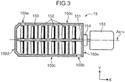
- FIG. 3 is a schematic cross-sectional top view showing the configuration and the arrangement of the pump 15.
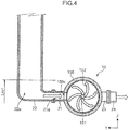
- FIG. 4 is a schematic cross-sectional end view showing the configuration and the arrangement of the pump 15.
- the pump 15 includes a casing 150, a rotary shaft 151, a plurality of impellers 152, a motor (drive source) 153, and a bearing 154.
- the casing 150 has a peripheral wall 150c forming a hollow cylinder, and an end wall 150d and another end wall 150e at the opposite ends in a longitudinal direction. As shown in FIGS. 2 and 3 , the casing 150 has a cylindrical shape which is longer in the longitudinal direction (X direction) than in a radial direction (Y, Z direction).
- the rotary shaft 151 has an axis Ax 15 extending in the X direction (horizontal direction).
- the rotary shaft 151 has an end extending outward through the end wall 150e of the casing 150 on the right in the X direction.
- the end of the rotary shaft 151 extending outward from the casing 150 is connected to a drive shaft 153a of the motor 153 serving as a drive source.
- the bearing 154 is attached to an outer surface of the end wall 150e of the casing 150, and supports the rotary shaft 151 in a state that the axis Ax 15 is kept in a horizontal posture (posture in the X direction).
- one end of the rotary shaft 151 is supported on the end wall 150e in this embodiment.
- both ends of the rotary shaft 151 may be supported respectively on the end wall 150d and the end wall 150e.
- the pump 15 is arranged in such a way that the Ax 15 of the rotary shaft 151 extends in the horizontal direction in the binary cycle power generation system 1 according to this embodiment, the Ax 15 of the rotary shaft 151 may permissibly intersect a vertical direction (Z direction) at other angles.
- the axis Ax 15 of the rotary shaft 151 may intersect the vertical direction (Z direction) at an angle of 75° or more to less than 90°.
- the plurality of impellers 152 are attached to a part of the rotary shaft 151 that is accommodated in the casing 150 one after another in the X direction.
- the plurality of impellers 152 rotate integrally with the rotary shaft 151 owing to the torque of the motor 153.
- the peripheral wall 150c of the casing 150 is formed with a suction port 150a and a discharge port 150b.
- the suction port 150a is formed in the left of the peripheral wall 150c (closer to the end wall 150d) in the X direction.
- the discharge port 150b is formed in the right of the peripheral wall 150c (closer to the end wall 150e) in the X direction.
- the suction port 150a of the pump 15 is connected with a pipe 22 via a suction port pipe 21, and the discharge port 150b (not shown in FIG. 4 ) is connected to a pipe 24 via a discharge port pipe 23.
- the working fluid coming in the liquid state from the condenser 14 is introduced into the casing 150 of the pump 15 after passing through an inside passage 22a of the pipe 22 and an inside passage 21a of the suction port pipe 21.
- the introduced working fluid advances in a rearward direction of FIG. 4 on the paper while being pressurized by the rotating impellers 152. Thereafter, the pressurized working fluid passes through the discharge port pipe 23 and the pipe 24, and goes to the preheater 11.
- the pump 15 in this embodiment is arranged in the horizontal posture in such a way that the axis Ax 15 of the rotary shaft 151 extends in the horizontal direction (X direction).
- This arrangement sufficiently enables the working fluid to reach the discharge port 150b while being pressurized by the pump 15, even when a liquid surface of the working fluid is at a low level or Level 1 as shown in FIG. 4 .
- a configuration and an arrangement of a comparative pump 95 will be described with reference to FIG. 5 in comparison with the above-described configuration and arrangement of the pump 15.
- the comparative pump 95 similarly includes a casing 950, a rotary shaft 951, a plurality of impellers 952, a motor 953, and a bearing 954.
- the rotary shaft 951, the impellers 952, the motor 953, and the bearing 954 among the components have no structural change from the rotary shaft 151, the impellers 152, the motor 153, and the bearing 154 respectively of the above-described pump 15. Thus, the description for these components will be omitted.
- the casing 950 of the pump 95 includes a peripheral wall 950c forming a hollow cylinder, an end wall 950d and another end wall 950e at the opposite ends in a longitudinal direction, and an outer wall 950f which extends along a part of the peripheral wall 950c to define a discharge passage 950g with the part of the peripheral wall 950c therebetween.
- the peripheral wall 950c of the casing 950 is formed with a suction port 950a at a lower position thereof (closer to the end wall 950d) in a Z direction, and is formed with a discharge port 950b at an upper position thereof (closer to the end wall 950e) in the Z direction.
- the outer wall 950f of the casing 950 is formed with an outer discharge port 950h at a lower position thereof in the Z direction.
- the comparative pump 95 is arranged in a vertical posture in such a way that an axis Ax 95 of the rotary shaft 951 extends in the Z direction (vertical direction).
- the suction port 950a is at a lower position and the discharge port 950b is at a higher position of the casing 950 in the Z direction.
- the suction port 950a is connected with a pipe 92 via a suction port pipe 91, and the outer discharge port 950h is connected with a pipe 94 via the discharge pipe 93.
- the working fluid coming from the condenser is introduced into the casing 950 from the suction port 950a after passing through an inside passage 92a of the pipe 92 and a suction port pipe 91.
- the introduced working fluid then advances upward in the Z direction while being pressurized by the rotating impellers 952. Thereafter, the pressurized working fluid flows out from the discharge port 950b, advances in the discharge passage 950g, further flows out from the outer discharge port 950h, passes through the discharge port pipe 93 and the pipe 94, and goes to the preheater.
- the pump 15 is arranged in the horizontal posture in such a way that the axis Ax 15 of the rotary shaft 151 extends in the substantially horizontal direction in the binary cycle power generation system 1 according to the first embodiment.
- the binary cycle power generation system 1 thus can prevent a cavitation from occurring in the casing 150 of the pump 15 in the restarting of the binary cycle power generation system 1 more effectively than a system including the comparative pump 95 arranged in the vertical posture in such a way that the Ax 95 of the rotary shaft 951 extends in the vertical direction (Z direction).
- the binary cycle power generation system 1 according to the first embodiment including the pump 15 arranged in the horizontal posture allows the working fluid to flow from the suction port 150a to the discharge port 150b more smoothly in the restarting of the system than the system including the comparative pump arranged in the horizontal posture, even when the liquid surface of the working fluid is at a low level or Level 1.
- the binary cycle power generation system 1 having this configuration in the first embodiment can prevent a cavitation from occurring in the casing 150 of the pump 15 in the restarting of the system 1.
- the binary recycle power generation system 1 can prevent a cavitation from occurring in the casing 150 of the pump 15 in the restarting of the system 1, and therefore can further avoid malfunction.
- the working fluid is allowed to smoothly flow into the casing 150 of the pump 15 in this embodiment in the restarting of the system 1. Hence, it is possible to prevent a gas from accumulating in the casing 150.
- the binary cycle power generation system 1 can avoid damage attributed to the accumulating gas to the pump.
- the binary cycle power generation system 1 consequently can avoid damage accompanied by the restarting of the system 1 to the bearing 154 of the pump 15, thereby achieving a high and long-term reliability.
- the comparative pump 95 is arranged in the vertical posture in such a way that the axis Ax 95 of the rotary shaft 951 extends in the vertical direction (Z direction).
- the liquid surface of the working fluid is required to be at a high level or Level 2 as shown in FIG. 5 in the inside passage 92a of the pipe 92 for the purpose of filling the casing 950 with the working fluid to start the pump 95.
- a cavitation may occur in the casing 950 when starting the pump 95 in the restarting of the system.
- the occurrence of the cavitation in the casing 950 may cause a gas to accumulate in an upper region (denoted by an arrow A) in the inside of the casing 950 in the Z direction.
- the accumulating gas in the upper region in the inside of the casing 950 in the Z direction as described above is likely to damage, for example, the bearing 954 due to the heat generated by the rotating rotary shaft 951, the bearing 954 facing the upper region containing the accumulating gas in the Z direction across the end wall 950e outside.
- FIG. 6 An overall configuration of a binary cycle power generation system 3 according to a second embodiment will be described with reference to FIG. 6 .
- the same structural components shown in FIG. 6 as those of the binary cycle power generation system 1 according to the first embodiment are given with the same reference signs, and the descriptions about these components will be omitted hereafter.
- the binary cycle power generation system 3 includes a working fluid circulation line 10, a preheater 11, an evaporator 12, an expander 13, a condenser 14, a pump 15, a power generator 16, an inverter 17, and a controller (control unit) 38.
- the binary cycle power generation system 3 according to this embodiment further includes a pressure detector 31, a temperature detector 32, and a cooling temperature detector 33.
- the pressure detector 31 is a detector which is provided in a portion between the condenser 14 and the pump 15 in the working fluid circulation line 10, and detects a pressure of the working fluid at an outlet of the condenser 14.
- the temperature detector 32 is a detector which is provided in a portion between the condenser 14 and the pump 15 in the working fluid circulation line 10 similarly to the pressure detector 31, and detects a temperature of the working fluid at the outlet of the condenser 14.
- the cooling temperature detector 33 is a sensor which is provided at a supply port to the condenser 14 in a cooling medium circulation line 20 connected to the condenser 14, and detects a temperature of a cooling medium (e.g., cooling water) supplied to the condenser 14.
- a cooling medium e.g., cooling water
- the controller 38 outputs a signal to the inverter 17 and controls driving of the motor 153 of the pump 15.
- the controller 38 differs from the controller 18 in the first embodiment in that the controller 38 receives the pressure information from the pressure detector 31, the temperature information from the temperature detector 32, and the cooling temperature information from the cooling temperature detector 33 one after another, and further utilizes the received information to control the driving (and stopping) of the motor 153.
- Control executed by the controller 38 when stopping the binary cycle power generation system 3 according to this embodiment will be described with reference to FIG. 7 .
- the controller 38 when stopping the system, firstly acquires pressure information Pr1 and temperature information Tr1 of the working fluid at the outlet of the condenser 14 in the working fluid circulation line 10 respectively from the pressure detector 31 and the temperature detector 32 (step S1).
- the controller 38 may acquire the pressure information Pr1 and the temperature information Tr1 timelessly or only when stopping the system.
- the controller 38 is configured to acquire the pressure information Pr1 and the temperature information Tr1 one after another.
- the controller 38 calculates a saturation temperature Ts from the acquired pressure information (a pressure of the working fluid at the outlet of the condenser 14) Pr1 (step S2). Subsequently, the controller 38 calculates a supercooling degree (Ts - Tr1) or a difference between the calculated saturation temperature Ts and the acquired temperature information (a temperature of the working fluid at the outlet of the condenser 14), and determines whether the supercooling degree (Ts - Tr1) is a predetermined (target) value "a" [°C] or more (step S3).
- the controller 38 re-executes steps S1 to S3 when the determination in step S3 results in (Ts - Tr1) ⁇ "a" ("No" in step S3).
- the predetermined value of the supercooling degree "a" [°C] in the determination in step S3 falls within a range of, for example, 1.0 [°C] to 2.0 [°C].
- the controller 38 acquires, from the cooling temperature detector 33, cooling temperature information (a temperature of the cooling medium supplied to the condenser 14) Tw1 (step S4) when the determination results in (Ts - Tr1) ⁇ "a" relative to the saturation temperature ("Yes” in step S3).
- the controller 38 further temporally stores the acquired cooling temperature information Tw1 as Tw1 (th) (step S5), and outputs to the inverter 17 an instruction of decreasing an inverter frequency of power supplied to the motor 153 of the pump 15 by a predetermined value "b" [Hz] (step S6), thereby reducing the rotational speed of the motor 153 of the pump 15 by 120 ⁇ b/p (rpm).
- the reference sign "p” denotes the pole number of the motor 153.
- the predetermined value "b" [Hz] falls within a range of, for example, 0.5 to 1.0 [Hz] in this embodiment.
- the controller 38 reacquires pressure information Pr1 and temperature information Tr1 of the working fluid at the outlet of the condenser 14 in the working fluid circulation line 10 at the time of having decreased the inverter frequency (step S7).
- the controller 38 recalculates a supercooling degree (Ts - Tr1) or a difference between a saturation temperature Ts and the acquired temperature information Tr1 by using the acquired temperature information Tr1, and determines whether the recalculated supercooling degree (Ts - Tr1) is the predetermined (target) value "a" [°C] or more (step S8).
- step S8 When the determination in step S8 results in (Ts - Tr1) ⁇ "a" ("Yes” in step S8), the controller 38 acquires cooling temperature information Tw1 of the cooling medium (step S9), and determines whether the acquired cooling temperature information Tw1 is lower than the cooling temperature information Tw1 (th) stored in step 5, that is, lower than the cooling temperature information Tw1 acquired before decreasing the inverter frequency (step S10).
- the controller 38 returns to step S1 and re-executes the control when the determination in either step S8 or S10 results in "No".
- the controller 38 subsequently determines whether the inverter frequency of the inverter 17 is less than a lower limit (step S11) when both the determinations in the steps S8 and S10 result in "Yes”.
- the controller 38 stops the driving of the motor 153 of the pump 15 (step S12) when the inverter frequency of the inverter 17 is determined to be less than the lower limit ("Yes" in step S11).
- the controller 38 repeats steps S5 to S11 when the inverter frequency is determined to be the lower limit or more in step S11 ("No" in step S11).
- the controller 38 in this embodiment reduces the rotational speed of the motor 153 of the pump 15 in a stepwise way, while keeping at the predetermined value "a" [°C] or more the supercooling degree (Ts - Tr1) based on the acquired three pieces of information (pressure information Pr1, temperature information Tr1, and cooling temperature information Tw1), until the system stops.
- the binary cycle power generation system 3 permits the controller 38 to, by executing the control shown in FIG. 7 , reduce the rotational speed of the motor 153 of the pump 15 in a stepwise or gradual way, while keeping at the predetermined value "a" [°C] or more the supercooling degree (Ts - Tr1) or a difference between the saturation temperature Ts and the temperature Tr1 of the working fluid at the outlet of the condenser 14 and reducing the pressure of the working fluid at the outlet of the condenser 14, until the system stops. Therefore, the system 3 can prevent a cavitation from occurring in the pump 15 in the restarting of the system 3, and further avoid malfunction.
- the motor 153 of the pump 15 in the binary cycle power generation system 3 is configured to stop the system by reducing the rotational speed of the motor 153 of the pump 15 in a stepwise or gradual way, while keeping at the predetermined value "a" [C°] or more the supercooling degree (Ts - Tr1) or the difference between the saturation temperature Ts and the temperature Tr1 of the working fluid at the outlet of the condenser 14 and reducing the pressure of the working fluid at the outlet of the condenser 14.
- This configuration makes it possible to keep the working fluid at the suction port 150a of the pump 15 from coming into the superheated state in the stopping of the system 3, and prevent a cavitation from occurring in the casing 150 of the pump 15 in the restating of the system 3.
- the binary cycle power generation system 3 according to this embodiment including the pump 15 arranged in the horizontal posture in the same manner as the first embodiment allows the working fluid to flow from the suction port 150a to the discharge port 150b more smoothly in the restarting of the system 3 than the system including the comparative pump arranged in the vertical direction, even when the liquid surface of the working fluid is at a low level or Level 1. Accordingly, the binary cycle power generation system 3 according to this embodiment can prevent a cavitation from occurring in the casing 150 of the pump 15 in the restarting of the system 3 as well as the binary cycle power generation system 1.
- the binary cycle power generation system 3 can reliably prevent a cavitation from occurring in the casing 150 of the pump 15 in the restarting of the system 3, and further avoid malfunction and damage to the pump 15 by adopting the above-described control by the controller 38 in combination with the same configuration and arrangement of the pump 15 according to the first embodiment.
- FIG. 8 An overall configuration of a binary cycle power generation system 5 according to a third embodiment will be described with reference to FIG. 8 .
- the same structural components shown in FIG. 8 as those of the binary cycle power generation systems 1 and 3 respectively according to the first and second embodiments are given with the same reference signs, and the descriptions about these components will be omitted hereafter.
- the binary cycle power generation system 5 includes a working fluid circulation line 50, a preheater 11, an evaporator 12, an expander 13, a condenser 54, a pump 15, a power generator 16, an inverter 17, and a controller (control unit) 58.
- the binary cycle power generation system 5 further includes a pressure detector 51 and a temperature detector 52 provided at an outlet of the condenser 54 in the working fluid circulation line 50, and a cooling temperature detector 53 which detects a temperature of a cooling medium supplied to the condenser 54.
- the pressure detector 51, the temperature detector 52, and the cooling temperature detector 53 in the binary cycle power generation system 5 according to this embodiment basically have the same functions as the pressure detector 31, the temperature detector 32, and the cooling temperature detector 33 in the binary cycle power generation system 3 according to the second embodiment.
- the condenser 54 in this embodiment includes a first condensing part 541 and a second condensing part 542 connected with each other in series in the working fluid circulation line 50.
- the first condensing part 541 is provided at an upstream position and the second condensing part 542 is provided at a downstream position in the working fluid circulation line 50.
- the first condensing part 541 is supplied with a cooling medium (e.g., cooling water) via a cooling medium circulation line 60
- a cooling medium e.g., cooling water
- a cooling medium circulation line 61 e.g., cooling water
- the first condensing part 541 and the second condensing part 542 cool the working fluid by using the cooling medium in the binary cycle power generation system 5 according to this embodiment even in stopping of the system.
- the pressure detector 51 and the temperature detector 52 are provided at the outlet of the second condensing part 542 in the working fluid circulation line 50.
- the pressure detector 541 and the heat detector 542 are provided at the outlet of the condenser 54 in the working fluid circulation line 50.
- the cooling temperature detector 53 is provided in the cooling medium circulation line 61 to the second condensing part 542 provided at a downstream position in the working fluid circulation line 50, and detects a temperature of the cooling medium supplied to the second condensing part 542.
- the controller 58 is configured to stop the system by reducing a rotational speed of a motor 153 of the pump 15 in a stepwise way while keeping at a predetermined value "a" [°C] or more a supercooling degree (Ts - Tr1) or the difference between the saturation temperature Ts and the temperature Tr1 of the working fluid at the outlet of the condenser based on acquired three pieces of information (pressure information Pr1, temperature information Tr1, and cooling temperature information Tw1), until the system stops.
- the controller 58 performs the same control as shown in FIG. 7 .
- the binary cycle power generation system 5 permits the controller 58 to reduce the rotational speed of the motor 153 of the pump 15 in a stepwise, while keeping at the predetermined value "a" [°C] or more the supercooling degree (Ts - Tr1) calculated based on the temperature Tr1 of the working fluid at the outlet of the condenser 54, until the system stops. Accordingly, the system 5 can prevent a cavitation from occurring in the pump 15 in the restarting of the system 5, and further avoid malfunction.
- the binary cycle power generation system 5 including the pump 15 arranged in the horizontal posture can prevent a cavitation from occurring in the casing 150 of the pump 15 in the restarting of the system 5 in the same manner as the first and second embodiments.
- the binary cycle power generation system 5 according to this embodiment including the condenser 54 constituted by the first condensing part 541 and the second condensing part 542 connected with each other in series in the working fluid circulation line 50 makes it possible to more efficiently cool the working fluid to go to the pump 15.
- the binary cycle power generation system 5 according to this embodiment permits the first condensing part 541 and the second condensing part 542 to condense the working fluid coming from the expander 13 in two stages respectively.
- the second condensing part 542 of the condenser 54 in this embodiment serves as a supercooler, and therefore is preferential to stop the system while keeping at the predetermined value "a" [°C] or more the supercooling degree (Ts - Tr1) calculated from a saturation temperature Ts and a temperature Tr1 of the working fluid at the outlet of the condenser 54.
- the binary cycle power generation system 3 can reliably prevent a cavitation from occurring in the casing 150 of the pump 15 in the restarting of the system and further avoid malfunction and damage to the pump 15 by adopting the above-described control by the controller 58 when stopping the system, in the same manner as the second embodiment, in combination with the same configuration and arrangement of the pump 15 in the first and second embodiments.
- the steam is supplied to the evaporator 12 via the steam supply line 19 in the first to third embodiments, the present invention should not be limited thereto.
- warm water or an exhaust gas may be supplied to the evaporator 12.
- an oil having a specified temperature may be supplied to the evaporator 12.
- the present invention should not be limited thereto.
- only the evaporator may be provided between the pump and the expander in the working fluid circulation line.
- the power generator 16 serving as an exemplary energy recovery apparatus is adopted in the first to third embodiments, the present invention should not be limited thereto.
- a compressor which compresses a gas or a liquid owing to a gained thermal energy is adoptable.
- the inverter frequency is decreased to reduce the rotational speed of the motor 153 of the pump 15 in the second and third embodiments
- the present invention should not be limited thereto.
- a control of reducing an applied voltage in addition to the decreasing of the inverter frequency i.e., a control based on an adjustable voltage adjustable frequency (AVAF) is adoptable.
- AVAF adjustable voltage adjustable frequency
- the rotational speed of the motor 153 of the pump 15 is reduced in a gradual way in accordance with a decrease in the clock frequency for the control of the controller 38, 58 in the second and third embodiments.
- the technical scope of the present invention should cover the features that a rotational speed of a motor of a pump is reduced in a stepwise way, and that the rotational speed is reduced in a gradual way.
- the pump 15 is arranged in such a way that the axis Ax 15 of the rotary shaft 151 extends in the horizontal direction in each of the binary cycle power generation systems 1, 3, 5 according to the first to third embodiments, the present invention should not be limited thereto.
- the Ax 15 of the rotary shaft 151 of the pump 15 may permissibly intersect a vertical direction (Z direction) at other angles in the present invention.
- the axis Ax 15 of the rotary shaft 151 may intersect the vertical direction (Z direction) at an angle of 75° or more to less than 90°.
- This arrangement makes it possible to prevent a cavitation from occurring in the casing 150 of the pump 15 in the restarting of the system more effectively than the arrangement of the comparative pump 95 where the axis Ax 95 of the rotational shaft 951 extends in the vertical direction as shown in FIG. 5 .
- impellers 152 are attached to the rotary shaft 150 in the pump 15 in the first to third embodiments, the present invention should not be limited thereto. Two to five, or seven or more impellers may be attached to the rotary shaft.
- the motor 153 is adopted as a drive source of the pump 15 in the first to third embodiments, the present invention should not be limited thereto.
- an internal combustion engine such as a gasoline engine and a diesel engine, a gas turbine, or an actuator driven owing to an air pressure or a hydraulic pressure is adoptable.
- it is not necessarily required to include a motor as a structural component of the pump.
- the pump may be driven by a torque from an external drive source.
- the controller 38, 58 is configured to execute the above-described control in addition to the arrangement of the pump 15 in the second and third embodiments, the present invention should not be limited thereto.
- the comparative pump 95 shown in FIG. 5 is adoptable in the system. Even in this adoption, it may be possible to substantially suppress occurrence of a cavitation in restarting of the system by way of execution of the control by the controller as shown in FIG. 7 .
- the arrangement where the axis Ax 15 of the rotary shaft 151 of the pump 15 intersects the vertical direction (Z direction) is advantageous in that a cavitation can be kept from occurring in restarting of the system.
- a gear pump, a vane pump, or a positive displacement pump such as a screw pump is adoptable.
- each of the pressure detector 31, 51, the temperature detector 32, 52, and the cooling temperature detector 33, 53 is singly provided in the second and third embodiments, the present invention should not be limited thereto.
- two or more detectors may be respectively provided to calculate average values thereof and further execute the control by using the average values, thereby enabling the control to be more precise.
- a countercurrent-type heat exchanger is used as a heat exchanger for each of the preheater 11, the evaporator 12, the condenser 14, 54 in the first to third embodiments
- the present invention should not be limited thereto.
- a parallel flow-type heat exchanger or a cross flow-type heat exchanger is adoptable.
- a binary cycle power generation system includes a working fluid circulation line, an evaporator, an expander, an energy recovery apparatus, a condenser, and a pump.
- the working fluid circulation line is a line through which a working fluid circulates.
- the evaporator is a structural component which is provided in the working fluid circulation line, and evaporates the working fluid owing to a gained thermal energy.
- the expander is a structural component which is provided at a downstream side with respect to the evaporator in the working fluid circulation line, and expands the working fluid coming from the evaporator.
- the energy recovery apparatus is a structural component which recovers a kinetic energy generated in the expander.
- the condenser is a structural component which is provided at a downstream side with respect to the expander in the working fluid circulation line, and condenses the working fluid coming from the expander owing to a heat exchange with a cooling medium.
- the pump is a structural component which is provided at a position downstream to the condenser and upstream to the evaporator in the working fluid circulation line, and causes the working fluid coming from the condenser to go to the evaporator.
- the pump includes a casing, a rotary shaft, and impellers.
- the casing is hollow and has an end wall at an end in a longitudinal direction.
- the rotary shaft is a structural component which has an axis extending in the longitudinal direction, which is supported on the end wall, at least a part of which is in the casing, and which rotates owing to a torque.
- the impellers are structural components attached to the rotary shaft one after another in the longitudinal direction.
- the pump is arranged in such a way that the axis of the rotary shaft intersects a vertical direction.
- the binary cycle power generation system includes the pump arranged in such a way that the axis of the rotary shaft intersects the vertical direction.
- the binary cycle power generation system can prevent a cavitation from occurring in the casing of the pump in the restarting of the system more effectively than a conventional system including a pump arranged in such a way that an axis of a rotary shaft extends in a vertical direction.
- the arrangement of the pump where the axis of the rotary shaft intersects the vertical section enables the working fluid to flow in the casing in the restarting of the system more smoothly than the arrangement of the pump where the axis of the rotary shaft extends in the vertical direction.
- the working fluid is cooled in the condenser even in the stopping of the system and the cooled working fluid flows in the casing of the pump, so that the working fluid is kept from coming into the saturation state around the suction port. In this way, it is possible to prevent a cavitation from occurring in the casing of the pump in the restarting of the system.
- the binary cycle power generation system can prevent a cavitation from occurring in the casing of the pump in the restarting of the system, and therefore ensure to cause the working fluid to go to the evaporator, and further avoid malfunction.
- the pump in this aspect makes it possible to suppress occurrence of a cavitation in the restarting, and therefore prevent a gas from accumulating and further reliably avoid damage thereto in the restarting.
- the binary cycle power generation system according to this aspect including the pump arranged in such a way that the axis of the rotary shaft intersects the vertical direction allows the working fluid to flow more smoothly when starting the pump than the system including the pump arranged in such a way that the axis of the rotary shaft extends in the vertical direction, thereby rapidly cooling the inside of the casing.
- the system according to this aspect can suppress occurrence of a cavitation and prevent the gas from accumulating, and thus avoid damage attributed to the accumulating gas to the pump.
- the binary cycle power generation system can avoid damage accompanied by the restarting of the system to the pump, thereby achieving a high and long-term reliability.
- the pump is arranged in such a way that the axis of the rotary shaft intersects the vertical direction at an angle of 75° to 90°.
- the binary cycle power generation system is effective to prevent a cavitation due to the working fluid from occurring in the pump in the restarting of system by way of the arrangement of the pump where the axis of the rotary shaft intersects the vertical direction at an angle of 75° to 90°.
- the pump is arranged in a lying state in the substantially horizontal direction (in a substantially horizontal state), and similarly, the flow passages of the working fluid in the casing extend in a substantially horizontal direction (in a substantially horizontal state).
- the working fluid is allowed to smoothly flow in the casing of the pump in the restarting of the system even in a situation that the liquid surface of the working fluid is at a low level and the inside of the pump is not always filled with the working fluid when the system is stopped. Accordingly, as described above, the system can prevent a cavitation from occurring in the casing of the pump, and further avoid malfunction and damage to the pump.
- a binary cycle power generation system having the above-described configuration further includes a controller which controls driving of the pump, wherein the controller reduces a rotational speed of a motor of the pump in a stepwise or gradual way, while keeping at a predetermined value or more a supercooling degree calculated based on a saturation temperature and a temperature of the working fluid between the condenser and the pump in the working fluid circulation line, and then stops the system.
- the binary cycle power generation system is configured to reduce the rotational speed of the motor of the pump in a stepwise or gradual way, while keeping at the predetermined value or more a supercooling degree based on the saturation temperature and the temperature of the working fluid at the outlet of the condenser, and then stop the system. Therefore, the system can suppress occurrence of a cavitation in the restarting of the system, and further avoid malfunction.
- the binary cycle power generation system is configured, as described above, to reduce the rotational speed of the motor of the pump in a stepwise or gradual way, while keeping at the predetermined value or more a supercooling degree calculated from the saturation temperature and the temperature of the working fluid at the outlet of the condenser, until the system stops. Accordingly, it is possible to avoid the superheated state at the suction port of the pump when stopping the system, and further prevent a cavitation from occurring in the casing of the pump in the restarting of the system.
- a binary cycle power generation system having the above-described configuration additionally includes a pressure detector, a temperature detector, and a cooling temperature detector.
- the pressure detector is a detector which is provided in a portion between the condenser and the pump in the working fluid circulation line, and detects a pressure of a working fluid in the specific portion.
- the temperature detector is a detector which is provided in the portion between the condenser and the pump in the working fluid circulation line, and detects a temperature of the working fluid in the portion.
- the cooling temperature detector is a detector which is provided in a supply line of the cooling medium to the condenser, and detects a temperature of the cooling medium in the supply line.
- controller sequentially executes the following operations:
- the controller repeats the rotational speed reduction and the cooling temperature comparison when the cooling temperature comparison results in that the cooling temperature information (a temperature of the cooling medium) after the execution of the rotational speed reduction is lower than the cooling temperature information (another temperature of the cooling medium) before the execution of the rotational speed reduction.
- the specific control operations executed by the controller are defined to stop the pump in the stepwise or gradual way, while keeping at the predetermined value "a” or more the supercooling degree (Ts - Tr1) or a difference from the temperature Tr1 of the working fluid at the outlet of the condenser.
- the controller executing the above-described operations makes it possible to suppress the superheated state at the suction port of the pump when stopping the system, and further prevent a cavitation from occurring in the pump in the restarting of the system.
- the condenser includes a first condensing part and a second condensing part connected with each other in series, the first condensing part being provided at an upstream position and the second condensing part being provided at a downstream position in the working fluid circulation line, and the cooling temperature detector is provided in a supply line of the cooling medium to the second condensing part.
- the condenser in the binary cycle power generation system is constituted by the first condensing part and the second condensing part connected with each other in series.
- the first condensing part and the second condensing part condense the working fluid coming from the expander in two stages respectively.
- the binary cycle power generation system can further reliably prevent a cavitation from occurring in the pump in the restarting of the system.
- the binary cycle power generation system includes a working fluid circulation line, an evaporator, an expander, an energy recovery apparatus, a condenser, a pump, a temperature detector, a pressure detector, and a cooling temperature detector.
- the working fluid circulation line is a line through which a working fluid circulates.
- the evaporator is a structural component which is provided in the working fluid circulation line, and evaporates the working fluid owing to a gained thermal energy.
- the expander is a structural component which is provided at a downstream position of the evaporator in the working fluid circulation line, and expands the working fluid coming from the evaporator.
- the energy recovery apparatus is a structural component which recovers a kinetic energy generated in the expander.
- the condenser is a structural component which is provided at a downstream position of the expander in the working fluid circulation line, and condenses the working fluid coming from the expander owing to a heat exchange with a cooling medium.
- the pump is a structural component which is provided at a position downstream of the condenser and upstream of the evaporator in the working fluid circulation line, and causes the working fluid coming from the condenser to go to the evaporator.
- the pressure detector is a detector which is provided between the condenser and the pump in the working fluid circulation line, and detects a pressure of the working fluid in the portion.
- the temperature detector is a detector which is provided between the condenser and the pump in the working fluid circulation line, and detects the temperature of the working fluid in the portion.
- the cooling temperature detector is a detector which is provided in a supply line of the cooling medium to the condenser, and detects a temperature of the cooling medium in the supply line.
- the method for stopping the binary cycle power generation system includes the following steps to be sequentially executed:
- the controller repeats the rotational speed reduction step and the cooling temperature comparison step when the cooling temperature comparison results in that the cooling temperature information (a temperature of the cooling medium) after the execution of the rotational speed reduction is lower than the cooling temperature information (another temperature of the cooling medium) before the execution of the rotational speed reduction.
- the binary cycle power generation system and the method for stopping the system according to the respective aspects of the present invention can prevent a cavitation from occurring in the pump in the restarting of the system.
Landscapes
- Engineering & Computer Science (AREA)
- Mechanical Engineering (AREA)
- General Engineering & Computer Science (AREA)
- Chemical & Material Sciences (AREA)
- Combustion & Propulsion (AREA)
- Engine Equipment That Uses Special Cycles (AREA)
- Structures Of Non-Positive Displacement Pumps (AREA)
- Control Of Turbines (AREA)
- Control Of Non-Positive-Displacement Pumps (AREA)
Abstract
Description
- The present invention relates to a binary cycle power generation system and a method for stopping the system, and particularly, relates to a binary cycle power generation system including a multistage centrifugal pump, and a method for stopping the system.
- Study and Development have recently been done to binary cycle power generation systems fulfilling as one of thermal energy recovery systems (e.g., Patent Literature 1). Such a binary cycle power generation system includes an evaporator, an expander, a condenser and a pump arranged in this order in a circulation line of a working fluid, and a power generator is connected to the expander. The evaporator evaporates the working fluid owing to gained steam or warm water. The expander expands the working fluid evaporated in the evaporator. The condenser condenses the working fluid coming from the expander owing to a heat exchange with cooling water.
- The binary cycle power generation system having this configuration which uses a working fluid having a boiling point lower than that of water to drive an expander makes it possible to generate power in a lower temperature range than a conventional power generation system which drives an expander directly by steam.
- Patent Literature 1: Japanese Unexamined Patent Publication No.
2012-202269 - However, the binary cycle power generation system according to the conventional technology has a problem that a cavitation occurs in a casing of the pump when the system is stopped in a state that the condenser has a high temperature, and then restarted. Specifically, when the system is stopped in the state that the condenser has a high temperature, the pressure rapidly decreases because the circulation of the working fluid stops, but the temperature in the condenser remains high, so that the working fluid comes into a saturation state. The working fluid at a suction port of the pump provided at a downstream position of the condenser consequently comes into the saturation state.
- When the system is restarted and the pump is driven in the saturation state of the working fluid at the suction port of the pump, the working fluid at the suction port comes into a superheated state, so that a cavitation occurs in the casing. The occurrence of the cavitation in the casing of the pump leads to malfunction of the system or damage to the pump.
- The present invention has been achieved to solve the above-described problems, and an object of the present invention is to provide a binary cycle power generation system which can prevent a cavitation from occurring in a pump in the restarting of the system.
- A binary cycle power generation system according to an aspect of the present invention includes a working fluid circulation line, an evaporator, an expander, an energy recovery apparatus, a condenser, and a pump.
- The working fluid circulation line is a line through which a working fluid circulates.
- The evaporator is a structural component which is provided in the working fluid circulation line, and evaporates the working fluid owing to a gained thermal energy.
- The expander is a structural component which is provided at a downstream side with respect to the evaporator in the working fluid circulation line, and expands the working fluid coming from the evaporator.
- The energy recovery apparatus is a structural component which recovers a kinetic energy generated in the expander.
- The condenser is a structural component which is provided at a downstream side with respect to the expander in the working fluid circulation line, and condenses the working fluid coming from the expander owing to a heat exchange with a cooling medium.
- The pump is a structural component which is provided at a position downstream of the condenser and upstream of the evaporator in the working fluid circulation line, and causes the working fluid coming from the condenser to go to the evaporator.
- The pump includes a casing, a rotary shaft, and impellers.
- The casing is hollow and has an end wall at an end in a longitudinal direction.
- The rotary shaft is a structural component which has an axis extending in the longitudinal direction, which is supported on the end wall, at least a part of which is in the casing, and which rotates owing to a torque.
- The impellers are structural components attached to the rotary shaft one after another in the longitudinal direction.
- The pump is arranged in such a way that the axis of the rotary shaft intersects a vertical direction.
-
-
FIG. 1 is a schematic diagram showing an overall configuration of a binary cycle power generation system according to a first embodiment. -
FIG. 2 is a schematic cross-sectional side view showing a configuration and arrangement of a pump in the first embodiment. -
FIG. 3 is a schematic cross-sectional top view showing the configuration and the arrangement of the pump in the first embodiment. -
FIG. 4 is a schematic cross-sectional end view showing the configuration and the arrangement of the pump in the first embodiment. -
FIG. 5 is a cross sectional view showing a configuration and an arrangement of a comparative pump. -
FIG. 6 is a schematic diagram showing a configuration of a binary cycle power generation system according to a second embodiment. -
FIG. 7 is a flowchart showing a control flow executed by a controller in the binary cycle power generation system according to the second embodiment when stopping the system. -
FIG. 8 is a schematic diagram showing a configuration of a binary cycle power generation system according to a third embodiment. - Hereinafter, embodiments will be described with reference to the accompanying drawings. It should be noted that the embodiments described below each merely represents an aspect of the present invention. Therefore, the present invention should not be limited to the embodiments except for essential configurations.
- An overall configuration of a binary cycle
power generation system 1 according to a first embodiment will be described with reference toFIG. 1 . - As shown in
FIG. 1 , the binary cyclepower generation system 1 according to the first embodiment includes a workingfluid circulation line 10, apreheater 11, anevaporator 12, anexpander 13, acondenser 14, apump 15, a power generator (energy recovery apparatus) 16, aninverter 17, and a controller (control unit) 18. - The working
fluid circulation line 10 is a line through which a working fluid circulates. Adopted as the working fluid is a fluid which has a lower boiling point than water and boils at room temperature, for example, a substitute Freon (e.g., HFC 245fa), a mixed liquid of ammonia and water, and an organic substance such as isopentane and isobutane. For instance, HFC 245fa is a medium which has a boiling point of 15. 3 [°C] and evaporates at room temperature. - Each of the
preheater 11 and theevaporator 12 is a heat exchanger having the principle of countercurrent devices. Specifically, thepreheater 11 and theevaporator 12 cause the working fluid to flow in the opposite direction to a direction in which steam or warm water passes through asteam supply line 19. Thepreheater 11 preheats the working fluid, and thereafter the evaporator evaporates the working fluid. - The
expander 13 is provided at a downstream position (at a downstream position in the flow direction of the working fluid) of theevaporator 12 in the workingfluid circulation line 10. Theexpander 13 expands the working fluid coming from theevaporator 12. Although the details of theexpander 13 are not shown in the drawings, a positive displacement screw expander including a pair of male and female screw rotors is adopted as theexpander 13 in this embodiment. - The
expander 13 has a pair of rotors to be driven owing to an expansion energy of the working fluid coming in a gaseous state. Theexpander 13 has arotary shaft 13a connected to one of the pair of screw rotors, extending outward, and having an end connected to thepower generator 16. - The
power generator 16 serves as an energy recovery apparatus in the binary cyclepower generation system 1 according to this embodiment. Thepower generator 16 generates power owing to a torque produced by theexpander 13. In this manner, the thermal energy of the supplied steam is acquired. - The
condenser 14 is provided at a downstream position of theexpander 13 in the workingfluid circulation line 10. Thecondenser 14 is a countercurrent-type heat exchanger in which the working fluid coming in the gaseous state from theexpander 13 and cooling medium (e.g., cooling water) passing through a coolingmedium circulation line 20 flow in the opposite directions and exchange heat with each other. Thecondenser 14 cools and condenses the working fluid coming in the aforementioned manner, and the condensed working fluid goes to thepump 15 in the liquid state. - The
pump 15 is provided at a position downstream of thecondenser 14 and upstream of thepreheater 11 in the workingfluid circulation line 10. Thepump 15, which will be described in detail later, includes a multistage centrifugal pump having a motor and a plurality of impellers rotated by the motor. Thepump 15 pressurizes the working fluid having entered therein to reach a predetermined value, and then causes the pressurized working fluid to flow into thepreheater 11. - The
inverter 17 is a device for driving the motor of thepump 15 at a variable speed. Theinverter 17 changes the speed of the motor by changing the frequency of power supplied to the motor of thepump 15. - The
controller 18 outputs to theinverter 17 an instruction of changing the speed of thepump 15 in accordance with input information. - A configuration and an arrangement of the
pump 15 in the binary cyclepower generation system 1 according to this embodiment will be described with reference toFIGS. 2 to 4 .FIG. 2 is a schematic cross-sectional side view showing the configuration and the arrangement of thepump 15.FIG. 3 is a schematic cross-sectional top view showing the configuration and the arrangement of thepump 15.FIG. 4 is a schematic cross-sectional end view showing the configuration and the arrangement of thepump 15. - As shown in
FIGS. 2 and3 , thepump 15 includes acasing 150, arotary shaft 151, a plurality ofimpellers 152, a motor (drive source) 153, and abearing 154. - The
casing 150 has aperipheral wall 150c forming a hollow cylinder, and anend wall 150d and anotherend wall 150e at the opposite ends in a longitudinal direction. As shown inFIGS. 2 and3 , thecasing 150 has a cylindrical shape which is longer in the longitudinal direction (X direction) than in a radial direction (Y, Z direction). - The
rotary shaft 151 has an axis Ax15 extending in the X direction (horizontal direction). Therotary shaft 151 has an end extending outward through theend wall 150e of thecasing 150 on the right in the X direction. The end of therotary shaft 151 extending outward from thecasing 150 is connected to adrive shaft 153a of themotor 153 serving as a drive source. - The
bearing 154 is attached to an outer surface of theend wall 150e of thecasing 150, and supports therotary shaft 151 in a state that the axis Ax15 is kept in a horizontal posture (posture in the X direction). In other words, one end of therotary shaft 151 is supported on theend wall 150e in this embodiment. However, both ends of therotary shaft 151 may be supported respectively on theend wall 150d and theend wall 150e. - Although the
pump 15 is arranged in such a way that the Ax15 of therotary shaft 151 extends in the horizontal direction in the binary cyclepower generation system 1 according to this embodiment, the Ax15 of therotary shaft 151 may permissibly intersect a vertical direction (Z direction) at other angles. For example, the axis Ax15 of therotary shaft 151 may intersect the vertical direction (Z direction) at an angle of 75° or more to less than 90°. - The plurality of
impellers 152 are attached to a part of therotary shaft 151 that is accommodated in thecasing 150 one after another in the X direction. The plurality ofimpellers 152 rotate integrally with therotary shaft 151 owing to the torque of themotor 153. - As shown in
FIG. 3 , theperipheral wall 150c of thecasing 150 is formed with asuction port 150a and adischarge port 150b. Thesuction port 150a is formed in the left of theperipheral wall 150c (closer to theend wall 150d) in the X direction. Thedischarge port 150b is formed in the right of theperipheral wall 150c (closer to theend wall 150e) in the X direction. - As shown in
FIG. 4 , thesuction port 150a of thepump 15 is connected with apipe 22 via asuction port pipe 21, and thedischarge port 150b (not shown inFIG. 4 ) is connected to apipe 24 via adischarge port pipe 23. - The working fluid coming in the liquid state from the
condenser 14 is introduced into thecasing 150 of thepump 15 after passing through aninside passage 22a of thepipe 22 and aninside passage 21a of thesuction port pipe 21. The introduced working fluid advances in a rearward direction ofFIG. 4 on the paper while being pressurized by the rotatingimpellers 152. Thereafter, the pressurized working fluid passes through thedischarge port pipe 23 and thepipe 24, and goes to thepreheater 11. - Here, as shown in
FIG. 2 , thepump 15 in this embodiment is arranged in the horizontal posture in such a way that the axis Ax15 of therotary shaft 151 extends in the horizontal direction (X direction). This arrangement sufficiently enables the working fluid to reach thedischarge port 150b while being pressurized by thepump 15, even when a liquid surface of the working fluid is at a low level orLevel 1 as shown inFIG. 4 . - A configuration and an arrangement of a
comparative pump 95 will be described with reference toFIG. 5 in comparison with the above-described configuration and arrangement of thepump 15. - As shown in
FIG. 5 , thecomparative pump 95 similarly includes acasing 950, arotary shaft 951, a plurality ofimpellers 952, amotor 953, and abearing 954. Therotary shaft 951, theimpellers 952, themotor 953, and thebearing 954 among the components have no structural change from therotary shaft 151, theimpellers 152, themotor 153, and thebearing 154 respectively of the above-describedpump 15. Thus, the description for these components will be omitted. - The
casing 950 of thepump 95 includes aperipheral wall 950c forming a hollow cylinder, anend wall 950d and anotherend wall 950e at the opposite ends in a longitudinal direction, and anouter wall 950f which extends along a part of theperipheral wall 950c to define adischarge passage 950g with the part of theperipheral wall 950c therebetween. - The
peripheral wall 950c of thecasing 950 is formed with asuction port 950a at a lower position thereof (closer to theend wall 950d) in a Z direction, and is formed with adischarge port 950b at an upper position thereof (closer to theend wall 950e) in the Z direction. Theouter wall 950f of thecasing 950 is formed with anouter discharge port 950h at a lower position thereof in the Z direction. - As shown in
FIG. 5 , thecomparative pump 95 is arranged in a vertical posture in such a way that an axis Ax95 of therotary shaft 951 extends in the Z direction (vertical direction). In this arrangement, thesuction port 950a is at a lower position and thedischarge port 950b is at a higher position of thecasing 950 in the Z direction. - The
suction port 950a is connected with apipe 92 via asuction port pipe 91, and theouter discharge port 950h is connected with apipe 94 via thedischarge pipe 93. - The working fluid coming from the condenser is introduced into the
casing 950 from thesuction port 950a after passing through aninside passage 92a of thepipe 92 and asuction port pipe 91. The introduced working fluid then advances upward in the Z direction while being pressurized by the rotatingimpellers 952. Thereafter, the pressurized working fluid flows out from thedischarge port 950b, advances in thedischarge passage 950g, further flows out from theouter discharge port 950h, passes through thedischarge port pipe 93 and thepipe 94, and goes to the preheater. - Hereinafter, advantageous effects of the binary cycle
power generation system 1 according to the first embodiment will be described in comparison with a system including thecomparative pump 95 shown inFIG. 5 . - As described with reference to
FIGS. 2 to 4 , thepump 15 is arranged in the horizontal posture in such a way that the axis Ax15 of therotary shaft 151 extends in the substantially horizontal direction in the binary cyclepower generation system 1 according to the first embodiment. The binary cyclepower generation system 1 thus can prevent a cavitation from occurring in thecasing 150 of thepump 15 in the restarting of the binary cyclepower generation system 1 more effectively than a system including thecomparative pump 95 arranged in the vertical posture in such a way that the Ax95 of therotary shaft 951 extends in the vertical direction (Z direction). - Specifically, the binary cycle
power generation system 1 according to the first embodiment including thepump 15 arranged in the horizontal posture allows the working fluid to flow from thesuction port 150a to thedischarge port 150b more smoothly in the restarting of the system than the system including the comparative pump arranged in the horizontal posture, even when the liquid surface of the working fluid is at a low level orLevel 1. - In this manner, the working fluid cooled in the condenser is allowed to smoothly enter into the
casing 150 of thepump 15 even in stopping of the binary cyclepower generation system 1, so that the working fluid is kept from coming into the saturation state around thesuction port 150a. The binary cyclepower generation system 1 having this configuration in the first embodiment can prevent a cavitation from occurring in thecasing 150 of thepump 15 in the restarting of thesystem 1. - As a result, the binary recycle
power generation system 1 can prevent a cavitation from occurring in thecasing 150 of thepump 15 in the restarting of thesystem 1, and therefore can further avoid malfunction. - Moreover, as described above, the working fluid is allowed to smoothly flow into the
casing 150 of thepump 15 in this embodiment in the restarting of thesystem 1. Hence, it is possible to prevent a gas from accumulating in thecasing 150. - Therefore, the binary cycle
power generation system 1 according to this embodiment can avoid damage attributed to the accumulating gas to the pump. - The binary cycle
power generation system 1 according to the first embodiment consequently can avoid damage accompanied by the restarting of thesystem 1 to the bearing 154 of thepump 15, thereby achieving a high and long-term reliability. - In contrast, as described with reference to
FIG. 5 , thecomparative pump 95 is arranged in the vertical posture in such a way that the axis Ax95 of therotary shaft 951 extends in the vertical direction (Z direction). In this arrangement, the liquid surface of the working fluid is required to be at a high level orLevel 2 as shown inFIG. 5 in theinside passage 92a of thepipe 92 for the purpose of filling thecasing 950 with the working fluid to start thepump 95. - If the liquid surface of the working fluid is at a lower level than
Level 2 in theinside passage 92a of thepipe 92 and the working fluid is insufficient to fill an inside of thecasing 950, a cavitation may occur in thecasing 950 when starting thepump 95 in the restarting of the system. The occurrence of the cavitation in thecasing 950 may cause a gas to accumulate in an upper region (denoted by an arrow A) in the inside of thecasing 950 in the Z direction. - The accumulating gas in the upper region in the inside of the
casing 950 in the Z direction as described above is likely to damage, for example, the bearing 954 due to the heat generated by the rotatingrotary shaft 951, the bearing 954 facing the upper region containing the accumulating gas in the Z direction across theend wall 950e outside. - Furthermore, such gas accumulation is likely to occur when starting the
pump 95 in the binary cycle power generation system including thecomparative pump 95 and thus hinder the working fluid from smoothly flowing out from thedischarge port 950b, which results in malfunction of the system. - An overall configuration of a binary cycle
power generation system 3 according to a second embodiment will be described with reference toFIG. 6 . The same structural components shown inFIG. 6 as those of the binary cyclepower generation system 1 according to the first embodiment are given with the same reference signs, and the descriptions about these components will be omitted hereafter. - As shown in
FIG. 6 , the binary cyclepower generation system 3 according to this embodiment includes a workingfluid circulation line 10, apreheater 11, anevaporator 12, anexpander 13, acondenser 14, apump 15, apower generator 16, aninverter 17, and a controller (control unit) 38. The binary cyclepower generation system 3 according to this embodiment further includes apressure detector 31, atemperature detector 32, and acooling temperature detector 33. - The
pressure detector 31 is a detector which is provided in a portion between thecondenser 14 and thepump 15 in the workingfluid circulation line 10, and detects a pressure of the working fluid at an outlet of thecondenser 14. - The
temperature detector 32 is a detector which is provided in a portion between thecondenser 14 and thepump 15 in the workingfluid circulation line 10 similarly to thepressure detector 31, and detects a temperature of the working fluid at the outlet of thecondenser 14. - The
cooling temperature detector 33 is a sensor which is provided at a supply port to thecondenser 14 in a coolingmedium circulation line 20 connected to thecondenser 14, and detects a temperature of a cooling medium (e.g., cooling water) supplied to thecondenser 14. - Like the
controller 18, thecontroller 38 outputs a signal to theinverter 17 and controls driving of themotor 153 of thepump 15. Thecontroller 38 differs from thecontroller 18 in the first embodiment in that thecontroller 38 receives the pressure information from thepressure detector 31, the temperature information from thetemperature detector 32, and the cooling temperature information from thecooling temperature detector 33 one after another, and further utilizes the received information to control the driving (and stopping) of themotor 153. - Control executed by the
controller 38 when stopping the binary cyclepower generation system 3 according to this embodiment will be described with reference toFIG. 7 . - As shown in
FIG. 7 , thecontroller 38, when stopping the system, firstly acquires pressure information Pr1 and temperature information Tr1 of the working fluid at the outlet of thecondenser 14 in the workingfluid circulation line 10 respectively from thepressure detector 31 and the temperature detector 32 (step S1). Thecontroller 38 may acquire the pressure information Pr1 and the temperature information Tr1 timelessly or only when stopping the system. In this embodiment, thecontroller 38 is configured to acquire the pressure information Pr1 and the temperature information Tr1 one after another. - Next, the
controller 38 calculates a saturation temperature Ts from the acquired pressure information (a pressure of the working fluid at the outlet of the condenser 14) Pr1 (step S2). Subsequently, thecontroller 38 calculates a supercooling degree (Ts - Tr1) or a difference between the calculated saturation temperature Ts and the acquired temperature information (a temperature of the working fluid at the outlet of the condenser 14), and determines whether the supercooling degree (Ts - Tr1) is a predetermined (target) value "a" [°C] or more (step S3). - The
controller 38 re-executes steps S1 to S3 when the determination in step S3 results in (Ts - Tr1) < "a" ("No" in step S3). - It should be noted that the predetermined value of the supercooling degree "a" [°C] in the determination in step S3 falls within a range of, for example, 1.0 [°C] to 2.0 [°C].
- Conversely, the
controller 38 acquires, from thecooling temperature detector 33, cooling temperature information (a temperature of the cooling medium supplied to the condenser 14) Tw1 (step S4) when the determination results in (Ts - Tr1) ≥ "a" relative to the saturation temperature ("Yes" in step S3). Thecontroller 38 further temporally stores the acquired cooling temperature information Tw1 as Tw1 (th) (step S5), and outputs to theinverter 17 an instruction of decreasing an inverter frequency of power supplied to themotor 153 of thepump 15 by a predetermined value "b" [Hz] (step S6), thereby reducing the rotational speed of themotor 153 of thepump 15 by 120 × b/p (rpm). The reference sign "p" denotes the pole number of themotor 153. - The predetermined value "b" [Hz] falls within a range of, for example, 0.5 to 1.0 [Hz] in this embodiment.
- Thereafter, the
controller 38 reacquires pressure information Pr1 and temperature information Tr1 of the working fluid at the outlet of thecondenser 14 in the workingfluid circulation line 10 at the time of having decreased the inverter frequency (step S7). Thecontroller 38 recalculates a supercooling degree (Ts - Tr1) or a difference between a saturation temperature Ts and the acquired temperature information Tr1 by using the acquired temperature information Tr1, and determines whether the recalculated supercooling degree (Ts - Tr1) is the predetermined (target) value "a" [°C] or more (step S8). When the determination in step S8 results in (Ts - Tr1) ≥ "a" ("Yes" in step S8), thecontroller 38 acquires cooling temperature information Tw1 of the cooling medium (step S9), and determines whether the acquired cooling temperature information Tw1 is lower than the cooling temperature information Tw1 (th) stored instep 5, that is, lower than the cooling temperature information Tw1 acquired before decreasing the inverter frequency (step S10). - The
controller 38 returns to step S1 and re-executes the control when the determination in either step S8 or S10 results in "No". - Meanwhile, the
controller 38 subsequently determines whether the inverter frequency of theinverter 17 is less than a lower limit (step S11) when both the determinations in the steps S8 and S10 result in "Yes". Thecontroller 38 stops the driving of themotor 153 of the pump 15 (step S12) when the inverter frequency of theinverter 17 is determined to be less than the lower limit ("Yes" in step S11). - The
controller 38 repeats steps S5 to S11 when the inverter frequency is determined to be the lower limit or more in step S11 ("No" in step S11). - As described above, the
controller 38 in this embodiment reduces the rotational speed of themotor 153 of thepump 15 in a stepwise way, while keeping at the predetermined value "a" [°C] or more the supercooling degree (Ts - Tr1) based on the acquired three pieces of information (pressure information Pr1, temperature information Tr1, and cooling temperature information Tw1), until the system stops. - The binary cycle
power generation system 3 according to this embodiment permits thecontroller 38 to, by executing the control shown inFIG. 7 , reduce the rotational speed of themotor 153 of thepump 15 in a stepwise or gradual way, while keeping at the predetermined value "a" [°C] or more the supercooling degree (Ts - Tr1) or a difference between the saturation temperature Ts and the temperature Tr1 of the working fluid at the outlet of thecondenser 14 and reducing the pressure of the working fluid at the outlet of thecondenser 14, until the system stops. Therefore, thesystem 3 can prevent a cavitation from occurring in thepump 15 in the restarting of thesystem 3, and further avoid malfunction. - As described above, if the pump abruptly stops in a state that the condenser has a high temperature, the pressure of the working fluid at a downstream position of the condenser rapidly decreases, but the temperature in the condenser remains high, so that the working fluid comes into a saturation state. The working fluid at the suction port of the pump comes consequently into the saturation state. The working fluid at the suction port of the pump comes into a superheated state when the system is restarted in this situation. As a result, a cavitation is likely to occur.
- In contrast, the
motor 153 of thepump 15 in the binary cyclepower generation system 3 according to this embodiment is configured to stop the system by reducing the rotational speed of themotor 153 of thepump 15 in a stepwise or gradual way, while keeping at the predetermined value "a" [C°] or more the supercooling degree (Ts - Tr1) or the difference between the saturation temperature Ts and the temperature Tr1 of the working fluid at the outlet of thecondenser 14 and reducing the pressure of the working fluid at the outlet of thecondenser 14. This configuration makes it possible to keep the working fluid at thesuction port 150a of thepump 15 from coming into the superheated state in the stopping of thesystem 3, and prevent a cavitation from occurring in thecasing 150 of thepump 15 in the restating of thesystem 3. - Furthermore, the binary cycle
power generation system 3 according to this embodiment including thepump 15 arranged in the horizontal posture in the same manner as the first embodiment allows the working fluid to flow from thesuction port 150a to thedischarge port 150b more smoothly in the restarting of thesystem 3 than the system including the comparative pump arranged in the vertical direction, even when the liquid surface of the working fluid is at a low level orLevel 1. Accordingly, the binary cyclepower generation system 3 according to this embodiment can prevent a cavitation from occurring in thecasing 150 of thepump 15 in the restarting of thesystem 3 as well as the binary cyclepower generation system 1. - Consequently, the binary cycle
power generation system 3 according to this embodiment can reliably prevent a cavitation from occurring in thecasing 150 of thepump 15 in the restarting of thesystem 3, and further avoid malfunction and damage to thepump 15 by adopting the above-described control by thecontroller 38 in combination with the same configuration and arrangement of thepump 15 according to the first embodiment. - An overall configuration of a binary cycle
power generation system 5 according to a third embodiment will be described with reference toFIG. 8 . The same structural components shown inFIG. 8 as those of the binary cyclepower generation systems - As shown in
FIG. 8 , the binary cyclepower generation system 5 according to this embodiment includes a workingfluid circulation line 50, apreheater 11, anevaporator 12, anexpander 13, acondenser 54, apump 15, apower generator 16, aninverter 17, and a controller (control unit) 58. The binary cyclepower generation system 5 further includes apressure detector 51 and atemperature detector 52 provided at an outlet of thecondenser 54 in the workingfluid circulation line 50, and acooling temperature detector 53 which detects a temperature of a cooling medium supplied to thecondenser 54. - The
pressure detector 51, thetemperature detector 52, and thecooling temperature detector 53 in the binary cyclepower generation system 5 according to this embodiment basically have the same functions as thepressure detector 31, thetemperature detector 32, and thecooling temperature detector 33 in the binary cyclepower generation system 3 according to the second embodiment. - As shown in
FIG. 8 , thecondenser 54 in this embodiment includes afirst condensing part 541 and asecond condensing part 542 connected with each other in series in the workingfluid circulation line 50. Thefirst condensing part 541 is provided at an upstream position and thesecond condensing part 542 is provided at a downstream position in the workingfluid circulation line 50. - The
first condensing part 541 is supplied with a cooling medium (e.g., cooling water) via a coolingmedium circulation line 60, and thesecond condensing part 542 is supplied with a cooling medium (e.g., cooling water) via a coolingmedium circulation line 61. - The
first condensing part 541 and thesecond condensing part 542 cool the working fluid by using the cooling medium in the binary cyclepower generation system 5 according to this embodiment even in stopping of the system. - The
pressure detector 51 and thetemperature detector 52 are provided at the outlet of thesecond condensing part 542 in the workingfluid circulation line 50. In other words, thepressure detector 541 and theheat detector 542 are provided at the outlet of thecondenser 54 in the workingfluid circulation line 50. - The
cooling temperature detector 53 is provided in the coolingmedium circulation line 61 to thesecond condensing part 542 provided at a downstream position in the workingfluid circulation line 50, and detects a temperature of the cooling medium supplied to thesecond condensing part 542. - Like the second embodiment, the
controller 58 is configured to stop the system by reducing a rotational speed of amotor 153 of thepump 15 in a stepwise way while keeping at a predetermined value "a" [°C] or more a supercooling degree (Ts - Tr1) or the difference between the saturation temperature Ts and the temperature Tr1 of the working fluid at the outlet of the condenser based on acquired three pieces of information (pressure information Pr1, temperature information Tr1, and cooling temperature information Tw1), until the system stops. Thecontroller 58 performs the same control as shown inFIG. 7 . - The binary cycle
power generation system 5 according to this embodiment, as well as the second embodiment, permits thecontroller 58 to reduce the rotational speed of themotor 153 of thepump 15 in a stepwise, while keeping at the predetermined value "a" [°C] or more the supercooling degree (Ts - Tr1) calculated based on the temperature Tr1 of the working fluid at the outlet of thecondenser 54, until the system stops. Accordingly, thesystem 5 can prevent a cavitation from occurring in thepump 15 in the restarting of thesystem 5, and further avoid malfunction. - Moreover, the binary cycle
power generation system 5 according to this embodiment including thepump 15 arranged in the horizontal posture can prevent a cavitation from occurring in thecasing 150 of thepump 15 in the restarting of thesystem 5 in the same manner as the first and second embodiments. - Furthermore, the binary cycle
power generation system 5 according to this embodiment including thecondenser 54 constituted by the first condensingpart 541 and thesecond condensing part 542 connected with each other in series in the workingfluid circulation line 50 makes it possible to more efficiently cool the working fluid to go to thepump 15. In other words, the binary cyclepower generation system 5 according to this embodiment permits the first condensingpart 541 and thesecond condensing part 542 to condense the working fluid coming from theexpander 13 in two stages respectively. - In this manner, it is possible to easily keep at the predetermined value or more the supercooling degree of the working fluid in the
pump 15 when stopping the system, and adjust the supercooling degree of the working fluid at thesuction port 150a of thepump 15 to an effective net positive suction head (NPSH) or more in the restarting of thesystem 5. - Hence, the
second condensing part 542 of thecondenser 54 in this embodiment serves as a supercooler, and therefore is preferential to stop the system while keeping at the predetermined value "a" [°C] or more the supercooling degree (Ts - Tr1) calculated from a saturation temperature Ts and a temperature Tr1 of the working fluid at the outlet of thecondenser 54. - Consequently, the binary cycle
power generation system 3 according to this embodiment can reliably prevent a cavitation from occurring in thecasing 150 of thepump 15 in the restarting of the system and further avoid malfunction and damage to thepump 15 by adopting the above-described control by thecontroller 58 when stopping the system, in the same manner as the second embodiment, in combination with the same configuration and arrangement of thepump 15 in the first and second embodiments. - Although the steam is supplied to the
evaporator 12 via thesteam supply line 19 in the first to third embodiments, the present invention should not be limited thereto. For example, warm water or an exhaust gas may be supplied to theevaporator 12. - Alternatively, an oil having a specified temperature may be supplied to the
evaporator 12. - Although the
preheater 11 and theevaporator 13 are provided between thepump 15 and theexpander 13 in the workingfluid circulation line - Although the
power generator 16 serving as an exemplary energy recovery apparatus is adopted in the first to third embodiments, the present invention should not be limited thereto. For example, a compressor which compresses a gas or a liquid owing to a gained thermal energy is adoptable. - Although the inverter frequency is decreased to reduce the rotational speed of the
motor 153 of thepump 15 in the second and third embodiments, the present invention should not be limited thereto. For example, a control of reducing an applied voltage in addition to the decreasing of the inverter frequency, i.e., a control based on an adjustable voltage adjustable frequency (AVAF), is adoptable. - Moreover, the rotational speed of the
motor 153 of thepump 15 is reduced in a gradual way in accordance with a decrease in the clock frequency for the control of thecontroller - Although the
pump 15 is arranged in such a way that the axis Ax15 of therotary shaft 151 extends in the horizontal direction in each of the binary cyclepower generation systems rotary shaft 151 of thepump 15 may permissibly intersect a vertical direction (Z direction) at other angles in the present invention. For example, the axis Ax15 of therotary shaft 151 may intersect the vertical direction (Z direction) at an angle of 75° or more to less than 90°. This arrangement makes it possible to prevent a cavitation from occurring in thecasing 150 of thepump 15 in the restarting of the system more effectively than the arrangement of thecomparative pump 95 where the axis Ax95 of therotational shaft 951 extends in the vertical direction as shown inFIG. 5 . - Although six
impellers 152 are attached to therotary shaft 150 in thepump 15 in the first to third embodiments, the present invention should not be limited thereto. Two to five, or seven or more impellers may be attached to the rotary shaft. - Although the
motor 153 is adopted as a drive source of thepump 15 in the first to third embodiments, the present invention should not be limited thereto. For example, an internal combustion engine such as a gasoline engine and a diesel engine, a gas turbine, or an actuator driven owing to an air pressure or a hydraulic pressure is adoptable. Furthermore, it is not necessarily required to include a motor as a structural component of the pump. Instead, the pump may be driven by a torque from an external drive source. - Although a cantilever structure that the one end of the
rotary shaft 151 of thepump 15 is supported is adopted in the first to third embodiments, the present invention should not be limited thereto. A both-end holding structure may be adopted. - Although the
controller pump 15 in the second and third embodiments, the present invention should not be limited thereto. For example, thecomparative pump 95 shown inFIG. 5 is adoptable in the system. Even in this adoption, it may be possible to substantially suppress occurrence of a cavitation in restarting of the system by way of execution of the control by the controller as shown inFIG. 7 . - However, as described above with reference to
FIGS. 2 to 5 , the arrangement where the axis Ax15 of therotary shaft 151 of thepump 15 intersects the vertical direction (Z direction) is advantageous in that a cavitation can be kept from occurring in restarting of the system. - Moreover, another type of pump other than the centrifugal pump may be adopted in the execution of the control in the second and third embodiments. For example, a gear pump, a vane pump, or a positive displacement pump such as a screw pump is adoptable.
- Although each of the
pressure detector temperature detector cooling temperature detector - Although a countercurrent-type heat exchanger is used as a heat exchanger for each of the
preheater 11, theevaporator 12, thecondenser - A binary cycle power generation system according to an aspect of the present invention includes a working fluid circulation line, an evaporator, an expander, an energy recovery apparatus, a condenser, and a pump.
- The working fluid circulation line is a line through which a working fluid circulates.
- The evaporator is a structural component which is provided in the working fluid circulation line, and evaporates the working fluid owing to a gained thermal energy.
- The expander is a structural component which is provided at a downstream side with respect to the evaporator in the working fluid circulation line, and expands the working fluid coming from the evaporator.
- The energy recovery apparatus is a structural component which recovers a kinetic energy generated in the expander.
- The condenser is a structural component which is provided at a downstream side with respect to the expander in the working fluid circulation line, and condenses the working fluid coming from the expander owing to a heat exchange with a cooling medium.
- The pump is a structural component which is provided at a position downstream to the condenser and upstream to the evaporator in the working fluid circulation line, and causes the working fluid coming from the condenser to go to the evaporator.
- The pump includes a casing, a rotary shaft, and impellers.
- The casing is hollow and has an end wall at an end in a longitudinal direction.
- The rotary shaft is a structural component which has an axis extending in the longitudinal direction, which is supported on the end wall, at least a part of which is in the casing, and which rotates owing to a torque.
- The impellers are structural components attached to the rotary shaft one after another in the longitudinal direction.
- The pump is arranged in such a way that the axis of the rotary shaft intersects a vertical direction.
- The binary cycle power generation system according to this aspect includes the pump arranged in such a way that the axis of the rotary shaft intersects the vertical direction. Hence, the binary cycle power generation system according to this aspect can prevent a cavitation from occurring in the casing of the pump in the restarting of the system more effectively than a conventional system including a pump arranged in such a way that an axis of a rotary shaft extends in a vertical direction.
- Specifically, the arrangement of the pump where the axis of the rotary shaft intersects the vertical section enables the working fluid to flow in the casing in the restarting of the system more smoothly than the arrangement of the pump where the axis of the rotary shaft extends in the vertical direction. The working fluid is cooled in the condenser even in the stopping of the system and the cooled working fluid flows in the casing of the pump, so that the working fluid is kept from coming into the saturation state around the suction port. In this way, it is possible to prevent a cavitation from occurring in the casing of the pump in the restarting of the system.
- Consequently, the binary cycle power generation system according to this aspect can prevent a cavitation from occurring in the casing of the pump in the restarting of the system, and therefore ensure to cause the working fluid to go to the evaporator, and further avoid malfunction.
- As described above, the pump in this aspect makes it possible to suppress occurrence of a cavitation in the restarting, and therefore prevent a gas from accumulating and further reliably avoid damage thereto in the restarting. In other words, the binary cycle power generation system according to this aspect including the pump arranged in such a way that the axis of the rotary shaft intersects the vertical direction allows the working fluid to flow more smoothly when starting the pump than the system including the pump arranged in such a way that the axis of the rotary shaft extends in the vertical direction, thereby rapidly cooling the inside of the casing. In this manner, the system according to this aspect can suppress occurrence of a cavitation and prevent the gas from accumulating, and thus avoid damage attributed to the accumulating gas to the pump.
- Accordingly, the binary cycle power generation system according to this aspect can avoid damage accompanied by the restarting of the system to the pump, thereby achieving a high and long-term reliability.
- In a binary cycle power generation system according to another aspect of the present invention having the above-described configuration, the pump is arranged in such a way that the axis of the rotary shaft intersects the vertical direction at an angle of 75° to 90°.
- The binary cycle power generation system according to this aspect is effective to prevent a cavitation due to the working fluid from occurring in the pump in the restarting of system by way of the arrangement of the pump where the axis of the rotary shaft intersects the vertical direction at an angle of 75° to 90°. In this aspect, specifically, the pump is arranged in a lying state in the substantially horizontal direction (in a substantially horizontal state), and similarly, the flow passages of the working fluid in the casing extend in a substantially horizontal direction (in a substantially horizontal state).
- In this arrangement, the working fluid is allowed to smoothly flow in the casing of the pump in the restarting of the system even in a situation that the liquid surface of the working fluid is at a low level and the inside of the pump is not always filled with the working fluid when the system is stopped. Accordingly, as described above, the system can prevent a cavitation from occurring in the casing of the pump, and further avoid malfunction and damage to the pump.
- A binary cycle power generation system according to still another aspect of the present invention having the above-described configuration further includes a controller which controls driving of the pump, wherein the controller reduces a rotational speed of a motor of the pump in a stepwise or gradual way, while keeping at a predetermined value or more a supercooling degree calculated based on a saturation temperature and a temperature of the working fluid between the condenser and the pump in the working fluid circulation line, and then stops the system.
- The binary cycle power generation system according to this aspect is configured to reduce the rotational speed of the motor of the pump in a stepwise or gradual way, while keeping at the predetermined value or more a supercooling degree based on the saturation temperature and the temperature of the working fluid at the outlet of the condenser, and then stop the system. Therefore, the system can suppress occurrence of a cavitation in the restarting of the system, and further avoid malfunction.
- Meanwhile, if the pump is stopped in a state that the condenser has a high temperature, the pressure of the working fluid at a downstream position of the condenser rapidly decreases, but the temperature in the condenser remains high, so that the working fluid comes into a saturation state. The working fluid at the suction port of the pump comes into a superheated state when the system is restarted in this situation. As a result, a cavitation is likely to occur in the casing of the pump.
- In contrast, the binary cycle power generation system according to this aspect is configured, as described above, to reduce the rotational speed of the motor of the pump in a stepwise or gradual way, while keeping at the predetermined value or more a supercooling degree calculated from the saturation temperature and the temperature of the working fluid at the outlet of the condenser, until the system stops. Accordingly, it is possible to avoid the superheated state at the suction port of the pump when stopping the system, and further prevent a cavitation from occurring in the casing of the pump in the restarting of the system.
- A binary cycle power generation system according to further another aspect of the present invention having the above-described configuration additionally includes a pressure detector, a temperature detector, and a cooling temperature detector.
- The pressure detector is a detector which is provided in a portion between the condenser and the pump in the working fluid circulation line, and detects a pressure of a working fluid in the specific portion.
- The temperature detector is a detector which is provided in the portion between the condenser and the pump in the working fluid circulation line, and detects a temperature of the working fluid in the portion.
- The cooling temperature detector is a detector which is provided in a supply line of the cooling medium to the condenser, and detects a temperature of the cooling medium in the supply line.
- In this aspect, the controller sequentially executes the following operations:
- a detection information reception: receiving temperature information from the temperature detector, pressure information from the pressure detector, and cooling temperature information from the cooling temperature detector one after another;
- a calculation: calculating a saturation temperature Ts from the pressure information (an acquired pressure of the working fluid at the outlet of the condenser);
- a determination: determining whether a supercooling degree (Ts - Tr1) that is a difference between the saturation temperature Ts and a temperature Tr1 of the working fluid at the outlet of the condenser is a predetermined value "a" or more;
- a rotational speed reduction: reducing a rotational speed of a motor of the pump by a predetermined value when the determination results in affirmation; and
- a cooling temperature comparison: comparing cooling temperature information (temperatures of the cooling medium) before and after the execution of the rotational speed reduction.
- In this aspect, the controller repeats the rotational speed reduction and the cooling temperature comparison when the cooling temperature comparison results in that the cooling temperature information (a temperature of the cooling medium) after the execution of the rotational speed reduction is lower than the cooling temperature information (another temperature of the cooling medium) before the execution of the rotational speed reduction.
- In this aspect, the specific control operations executed by the controller are defined to stop the pump in the stepwise or gradual way, while keeping at the predetermined value "a" or more the supercooling degree (Ts - Tr1) or a difference from the temperature Tr1 of the working fluid at the outlet of the condenser. The controller executing the above-described operations makes it possible to suppress the superheated state at the suction port of the pump when stopping the system, and further prevent a cavitation from occurring in the pump in the restarting of the system.
- In a binary cycle power generation system according to still further another aspect of the present invention having the above-described configuration, the condenser includes a first condensing part and a second condensing part connected with each other in series, the first condensing part being provided at an upstream position and the second condensing part being provided at a downstream position in the working fluid circulation line, and the cooling temperature detector is provided in a supply line of the cooling medium to the second condensing part.
- The condenser in the binary cycle power generation system according to this aspect is constituted by the first condensing part and the second condensing part connected with each other in series. In this aspect, in other words, the first condensing part and the second condensing part condense the working fluid coming from the expander in two stages respectively.
- In this manner, it is possible to easily keep at the predetermined value or more the super cooling degree of the working fluid in the pump when stopping the system, and adjust the super cooling degree of the working fluid at the suction port of the pump to an effective net positive suction head (NPSH) or more in the restarting of the system.
- Consequently, the binary cycle power generation system according to this aspect can further reliably prevent a cavitation from occurring in the pump in the restarting of the system.
- In a method for stopping a binary cycle power generation system according to an aspect of the present invention, the binary cycle power generation system includes a working fluid circulation line, an evaporator, an expander, an energy recovery apparatus, a condenser, a pump, a temperature detector, a pressure detector, and a cooling temperature detector.
- The working fluid circulation line is a line through which a working fluid circulates.
- The evaporator is a structural component which is provided in the working fluid circulation line, and evaporates the working fluid owing to a gained thermal energy.
- The expander is a structural component which is provided at a downstream position of the evaporator in the working fluid circulation line, and expands the working fluid coming from the evaporator.
- The energy recovery apparatus is a structural component which recovers a kinetic energy generated in the expander.
- The condenser is a structural component which is provided at a downstream position of the expander in the working fluid circulation line, and condenses the working fluid coming from the expander owing to a heat exchange with a cooling medium.
- The pump is a structural component which is provided at a position downstream of the condenser and upstream of the evaporator in the working fluid circulation line, and causes the working fluid coming from the condenser to go to the evaporator.
- The pressure detector is a detector which is provided between the condenser and the pump in the working fluid circulation line, and detects a pressure of the working fluid in the portion.
- The temperature detector is a detector which is provided between the condenser and the pump in the working fluid circulation line, and detects the temperature of the working fluid in the portion.
- The cooling temperature detector is a detector which is provided in a supply line of the cooling medium to the condenser, and detects a temperature of the cooling medium in the supply line.
- The method for stopping the binary cycle power generation system according to this aspect includes the following steps to be sequentially executed:
- a detection information reception step: receiving temperature information from the temperature detector, pressure information from the pressure detector, and cooling temperature information from the cooling temperature detector one after another;
- a calculation step: calculating a saturation temperature Ts from the pressure information (an acquired pressure of the working fluid at the outlet of the condenser);
- a determination step: determining whether a supercooling degree (Ts - Tr1) that is a difference between the saturation temperature Ts and a temperature Tr1 of the working fluid at the outlet of the condenser is a predetermined value "a" or more;
- a rotational speed reduction step: reducing a rotational speed of a motor of the pump by a predetermined value when the determination results in affirmation; and
- a cooling temperature comparison step: comparing cooling temperature information (temperatures of the cooling medium) before and after the execution of the rotational speed reduction step.
- In this aspect, the controller repeats the rotational speed reduction step and the cooling temperature comparison step when the cooling temperature comparison results in that the cooling temperature information (a temperature of the cooling medium) after the execution of the rotational speed reduction is lower than the cooling temperature information (another temperature of the cooling medium) before the execution of the rotational speed reduction.
- Conclusively, the binary cycle power generation system and the method for stopping the system according to the respective aspects of the present invention can prevent a cavitation from occurring in the pump in the restarting of the system.
Claims (6)
- A binary cycle power generation system comprising:a working fluid circulation line through which a working fluid circulates;an evaporator provided in the working fluid circulation line, and configured to evaporate the working fluid owing to a gained thermal energy;an expander provided at a downstream side with respect to the evaporator in the working fluid circulation line, and configured to expand the working fluid coming from the evaporator;an energy recovery apparatus configured to recover a kinetic energy generated in the expander;a condenser provided at a downstream side with respect to the expander in the working fluid circulation line, and configured to condense the working fluid coming from the expander owing to a heat exchange with a cooling medium; anda pump provided at a position downstream to the condenser and upstream to the evaporator in the working fluid circulation line, and configured to cause the working fluid coming from the condenser to go to the evaporator, whereinthe pump includes:a hollow casing having an end wall at an end in a longitudinal direction;a rotary shaft which has an axis extending in the longitudinal direction, which is supported on the end wall, at least a part of which is in the casing, and which rotates owing to a torque; anda plurality of impellers attached to the rotary shaft one after another in the longitudinal direction, andthe axis of the rotary shaft intersecting a vertical direction.
- A binary cycle power generation system according to claim 1, wherein
the axis of the rotary shaft intersects the vertical direction at an angle of 75° to 90°. - A binary cycle power generation system according to claim 1 or 2, further comprising:a controller configured to control driving of the pump, whereinthe controller reduces a rotational speed of a motor of the pump in a stepwise or gradual way, while keeping at a predetermined value or more a supercooling degree calculated based on a difference between a saturation temperature and a temperature of the working fluid at an outlet of the condenser between the condenser and the pump in the working fluid circulation line, until the system stops.
- A binary cycle power generation system according to claim 3, further comprising:a temperature detector provided in a portion between the condenser and the pump in the working media circulation line and configured to detect a temperature of the working fluid in the portion;a pressure detector provided in the portion and configured to detect a pressure of the working fluid in the portion;a cooling temperature detector provided in a supply line of the cooling medium to the condenser, and configured to detect a temperature of the cooling medium in the supply line, whereinthe controller is configured to sequentially execute:a detection information reception of receiving temperature information from the temperature detector, pressure information from the pressure detector, and cooling temperature information from the cooling temperature detector one after another;a calculation of calculating a saturation temperature Ts from the pressure information;a determination of determining whether a supercooling degree (Ts - Tr1) that is a difference between the saturation temperature Ts and a temperature Tr1 of the working fluid at the outlet of the condenser is a predetermined value or more;a rotational speed reduction of reducing a rotational speed of a motor of the pump by a predetermined value when the determination results in affirmation; anda cooling temperature comparison of comparing cooling temperature information before and after the execution of the rotational speed reduction,the controller repeating the rotational speed reduction and the cooling temperature comparison when the cooling temperature comparison results in that the cooling media temperature information after the execution of the rotational speed reduction is lower than the cooling media temperature information before the execution of the rotational speed reduction.
- A binary cycle power generation system according to claim 4, wherein
the condenser includes a first condensing part and a second condensing part connected with each other in series, the first condensing part being provided at an upstream position and the second condensing part being provided at a downstream position in the working fluid circulation line, and
the cooling temperature detector is provided in a supply line of the cooling medium to the second condensing part. - A method for stopping a binary cycle power generation system, the system including:a working fluid circulation line through which a working fluid circulates;an evaporator provided in the working fluid circulation line, and configured to evaporate the working fluid owing to a gained thermal energy;an expander provided at a downstream side with respect to the evaporator in the working fluid circulation line, and configured to expand the working fluid coming from the evaporator;an energy recovery apparatus configured to recover a kinetic energy generated in the expander;a condenser provided at a downstream side with respect to the expander in the working fluid circulation line, and configured to condense the working fluid coming from the expander owing to a heat exchange with a cooling medium;a pump provided at a position downstream of the condenser and upstream of the evaporator in the working fluid circulation line, and configured to cause the working fluid coming from the condenser to go to the evaporator;a temperature detector provided in a portion between the condenser and the pump in the working media circulation line and configured to detect a temperature of the working fluid in the portion;a pressure detector provided in the portion and configured to detect a pressure of the working fluid in the portion; anda cooling temperature detector provided in a supply line of the cooling medium to the condenser, and configured to detect a temperature of the cooling medium in the supply line, whereinthe method, when stopping the system, sequentially execute:a detection information reception step of receiving temperature information from the temperature detector, pressure information from the pressure detector, and cooling temperature information from the cooling temperature detector one after another;a calculation step of calculating a saturation temperature Ts from the pressure information;a determination step of determining whether a supercooling degree (Ts - Tr1) that is a difference between the saturation temperature Ts and a temperature Tr1 of the working fluid at the outlet of the condenser is a predetermined value or more;a rotational speed reduction step of reducing a rotational speed of a motor of the pump by a predetermined value when the determination in the determination step results in affirmation; anda cooling temperature comparison step of comparing cooling temperature information before and after execution of the rotational speed reduction step,the rotational speed reduction step and the cooling temperature comparison step being repeated when the comparison in the cooling temperature comparison step results in that the cooling temperature information after the execution of the rotational speed reduction step is lower than the cooling temperature information before the execution of the rotational speed reduction step.
Applications Claiming Priority (2)
| Application Number | Priority Date | Filing Date | Title |
|---|---|---|---|
| JP2017020997A JP6763797B2 (en) | 2017-02-08 | 2017-02-08 | Binary power generation system |
| PCT/JP2018/001297 WO2018147027A1 (en) | 2017-02-08 | 2018-01-18 | Binary power generation system and stopping method for same |
Publications (2)
| Publication Number | Publication Date |
|---|---|
| EP3564539A1 true EP3564539A1 (en) | 2019-11-06 |
| EP3564539A4 EP3564539A4 (en) | 2020-08-19 |
Family
ID=63108013
Family Applications (1)
| Application Number | Title | Priority Date | Filing Date |
|---|---|---|---|
| EP18750856.9A Withdrawn EP3564539A4 (en) | 2017-02-08 | 2018-01-18 | Binary power generation system and stopping method for same |
Country Status (6)
| Country | Link |
|---|---|
| US (1) | US10794229B2 (en) |
| EP (1) | EP3564539A4 (en) |
| JP (1) | JP6763797B2 (en) |
| KR (1) | KR20190108625A (en) |
| CN (1) | CN110214232B (en) |
| WO (1) | WO2018147027A1 (en) |
Families Citing this family (1)
| Publication number | Priority date | Publication date | Assignee | Title |
|---|---|---|---|---|
| WO2020116061A1 (en) * | 2018-12-07 | 2020-06-11 | パナソニック株式会社 | Rankine cycle device and control method therefor |
Family Cites Families (18)
| Publication number | Priority date | Publication date | Assignee | Title |
|---|---|---|---|---|
| JPS6014962B2 (en) * | 1978-04-05 | 1985-04-17 | 株式会社日立製作所 | Forced recirculation steam generator |
| US5174726A (en) * | 1989-09-05 | 1992-12-29 | Findlay Iain S | Liquid pump |
| US6296459B1 (en) * | 2000-02-15 | 2001-10-02 | Intex Recreation Corp. | Electric air pump having multiple impellers and method |
| JP2002372343A (en) * | 2001-03-28 | 2002-12-26 | Mitsubishi Electric Corp | Refrigerant cycle device, pump device |
| US7036315B2 (en) * | 2003-12-19 | 2006-05-02 | United Technologies Corporation | Apparatus and method for detecting low charge of working fluid in a waste heat recovery system |
| US7775045B2 (en) * | 2005-10-31 | 2010-08-17 | Ormat Technologies, Inc. | Method and system for producing power from a source of steam |
| WO2008124890A1 (en) * | 2007-04-17 | 2008-10-23 | Innovative Design Technology Pty Limited | Energy transfer system |
| US8186161B2 (en) * | 2007-12-14 | 2012-05-29 | General Electric Company | System and method for controlling an expansion system |
| US7866157B2 (en) * | 2008-05-12 | 2011-01-11 | Cummins Inc. | Waste heat recovery system with constant power output |
| KR101093544B1 (en) * | 2009-05-13 | 2011-12-14 | 한국항공우주연구원 | Test method and test equipment for checking cavitation characteristics of pump |
| JP5338731B2 (en) * | 2010-03-29 | 2013-11-13 | 株式会社豊田自動織機 | Waste heat regeneration system |
| US8813498B2 (en) * | 2010-06-18 | 2014-08-26 | General Electric Company | Turbine inlet condition controlled organic rankine cycle |
| JP5639515B2 (en) * | 2011-03-24 | 2014-12-10 | 株式会社神戸製鋼所 | Binary power generator and control method thereof |
| JP5597597B2 (en) * | 2011-06-09 | 2014-10-01 | 株式会社神戸製鋼所 | Power generator |
| JP5891146B2 (en) * | 2012-08-29 | 2016-03-22 | 株式会社神戸製鋼所 | Power generation device and method for controlling power generation device |
| JP6064548B2 (en) * | 2012-11-28 | 2017-01-25 | 株式会社Ihi | Waste heat power generator |
| CN104633458B (en) * | 2015-02-14 | 2017-08-29 | 西安热工研究院有限公司 | A kind of thermal power station's water pump real-time online Cavitation detection early warning system and method |
| JP6277148B2 (en) * | 2015-03-06 | 2018-02-07 | ヤンマー株式会社 | Power generator |
-
2017
- 2017-02-08 JP JP2017020997A patent/JP6763797B2/en active Active
-
2018
- 2018-01-18 KR KR1020197025741A patent/KR20190108625A/en not_active Ceased
- 2018-01-18 CN CN201880008799.5A patent/CN110214232B/en not_active Expired - Fee Related
- 2018-01-18 US US16/480,321 patent/US10794229B2/en not_active Expired - Fee Related
- 2018-01-18 WO PCT/JP2018/001297 patent/WO2018147027A1/en not_active Ceased
- 2018-01-18 EP EP18750856.9A patent/EP3564539A4/en not_active Withdrawn
Also Published As
| Publication number | Publication date |
|---|---|
| WO2018147027A1 (en) | 2018-08-16 |
| US20190383176A1 (en) | 2019-12-19 |
| JP6763797B2 (en) | 2020-09-30 |
| US10794229B2 (en) | 2020-10-06 |
| CN110214232A (en) | 2019-09-06 |
| KR20190108625A (en) | 2019-09-24 |
| JP2018127942A (en) | 2018-08-16 |
| EP3564539A4 (en) | 2020-08-19 |
| CN110214232B (en) | 2021-01-29 |
Similar Documents
| Publication | Publication Date | Title |
|---|---|---|
| KR101482879B1 (en) | Power generating apparatus and operation method thereof | |
| JP2009097434A (en) | Waste heat utilization device for internal combustion engine | |
| EP2532844B1 (en) | Power generation apparatus | |
| US10364708B2 (en) | Rankine cycle apparatus, combined heat and power system, and rankine cycle apparatus operation method | |
| KR101707744B1 (en) | Compressing device | |
| KR101600687B1 (en) | Heat recovery apparatus and operation control method of heat recovery apparatus | |
| CN101571138A (en) | Centrifugal compressor and turbine refrigerator using the same | |
| KR101361253B1 (en) | Power generating apparatus | |
| US9964001B2 (en) | Thermal energy recovery device | |
| JP6604355B2 (en) | Waste heat recovery device | |
| US9850895B2 (en) | Liquid pump and rankine cycle apparatus | |
| US8739532B2 (en) | Exhaust heat regeneration system | |
| US10794229B2 (en) | Binary power generation system and stopping method for same | |
| US9850783B2 (en) | Liquid pump including a gas accumulation area and rankine cycle device including a liquid pump | |
| JP6595395B2 (en) | Thermal energy recovery device and operation method thereof | |
| US10358948B2 (en) | Thermal energy recovery device | |
| JP6597117B2 (en) | Output device and output device control method | |
| JP2007183078A (en) | Refrigerating machine and refrigerating device | |
| CN105822369B (en) | A kind of control method of organic Rankine cycle power generation system |
Legal Events
| Date | Code | Title | Description |
|---|---|---|---|
| STAA | Information on the status of an ep patent application or granted ep patent |
Free format text: STATUS: THE INTERNATIONAL PUBLICATION HAS BEEN MADE |
|
| PUAI | Public reference made under article 153(3) epc to a published international application that has entered the european phase |
Free format text: ORIGINAL CODE: 0009012 |
|
| STAA | Information on the status of an ep patent application or granted ep patent |
Free format text: STATUS: REQUEST FOR EXAMINATION WAS MADE |
|
| 17P | Request for examination filed |
Effective date: 20190801 |
|
| AK | Designated contracting states |
Kind code of ref document: A1 Designated state(s): AL AT BE BG CH CY CZ DE DK EE ES FI FR GB GR HR HU IE IS IT LI LT LU LV MC MK MT NL NO PL PT RO RS SE SI SK SM TR |
|
| A4 | Supplementary search report drawn up and despatched |
Effective date: 20200717 |
|
| RIC1 | Information provided on ipc code assigned before grant |
Ipc: F01D 17/08 20060101ALI20200713BHEP Ipc: F01D 21/00 20060101ALI20200713BHEP Ipc: F04D 29/66 20060101AFI20200713BHEP Ipc: F01K 25/10 20060101ALI20200713BHEP Ipc: F04D 29/62 20060101ALI20200713BHEP Ipc: F04D 15/00 20060101ALI20200713BHEP Ipc: F01K 23/04 20060101ALI20200713BHEP Ipc: F01D 17/00 20060101ALI20200713BHEP Ipc: F04D 1/06 20060101ALI20200713BHEP Ipc: F01K 23/10 20060101ALI20200713BHEP |
|
| GRAP | Despatch of communication of intention to grant a patent |
Free format text: ORIGINAL CODE: EPIDOSNIGR1 |
|
| STAA | Information on the status of an ep patent application or granted ep patent |
Free format text: STATUS: GRANT OF PATENT IS INTENDED |
|
| INTG | Intention to grant announced |
Effective date: 20220126 |
|
| STAA | Information on the status of an ep patent application or granted ep patent |
Free format text: STATUS: THE APPLICATION IS DEEMED TO BE WITHDRAWN |
|
| 18D | Application deemed to be withdrawn |
Effective date: 20220608 |