EP3564537A1 - Centrifugal compressor and turbocharger - Google Patents
Centrifugal compressor and turbocharger Download PDFInfo
- Publication number
- EP3564537A1 EP3564537A1 EP17904232.0A EP17904232A EP3564537A1 EP 3564537 A1 EP3564537 A1 EP 3564537A1 EP 17904232 A EP17904232 A EP 17904232A EP 3564537 A1 EP3564537 A1 EP 3564537A1
- Authority
- EP
- European Patent Office
- Prior art keywords
- hub
- wall surface
- diffuser
- flow path
- centrifugal compressor
- Prior art date
- Legal status (The legal status is an assumption and is not a legal conclusion. Google has not performed a legal analysis and makes no representation as to the accuracy of the status listed.)
- Granted
Links
Images


Classifications
-
- F—MECHANICAL ENGINEERING; LIGHTING; HEATING; WEAPONS; BLASTING
- F04—POSITIVE - DISPLACEMENT MACHINES FOR LIQUIDS; PUMPS FOR LIQUIDS OR ELASTIC FLUIDS
- F04D—NON-POSITIVE-DISPLACEMENT PUMPS
- F04D29/00—Details, component parts, or accessories
- F04D29/40—Casings; Connections of working fluid
- F04D29/42—Casings; Connections of working fluid for radial or helico-centrifugal pumps
- F04D29/44—Fluid-guiding means, e.g. diffusers
- F04D29/441—Fluid-guiding means, e.g. diffusers especially adapted for elastic fluid pumps
-
- F—MECHANICAL ENGINEERING; LIGHTING; HEATING; WEAPONS; BLASTING
- F04—POSITIVE - DISPLACEMENT MACHINES FOR LIQUIDS; PUMPS FOR LIQUIDS OR ELASTIC FLUIDS
- F04D—NON-POSITIVE-DISPLACEMENT PUMPS
- F04D17/00—Radial-flow pumps, e.g. centrifugal pumps; Helico-centrifugal pumps
- F04D17/08—Centrifugal pumps
- F04D17/10—Centrifugal pumps for compressing or evacuating
-
- F—MECHANICAL ENGINEERING; LIGHTING; HEATING; WEAPONS; BLASTING
- F04—POSITIVE - DISPLACEMENT MACHINES FOR LIQUIDS; PUMPS FOR LIQUIDS OR ELASTIC FLUIDS
- F04D—NON-POSITIVE-DISPLACEMENT PUMPS
- F04D29/00—Details, component parts, or accessories
- F04D29/26—Rotors specially for elastic fluids
- F04D29/28—Rotors specially for elastic fluids for centrifugal or helico-centrifugal pumps for radial-flow or helico-centrifugal pumps
- F04D29/284—Rotors specially for elastic fluids for centrifugal or helico-centrifugal pumps for radial-flow or helico-centrifugal pumps for compressors
-
- F—MECHANICAL ENGINEERING; LIGHTING; HEATING; WEAPONS; BLASTING
- F04—POSITIVE - DISPLACEMENT MACHINES FOR LIQUIDS; PUMPS FOR LIQUIDS OR ELASTIC FLUIDS
- F04D—NON-POSITIVE-DISPLACEMENT PUMPS
- F04D29/00—Details, component parts, or accessories
- F04D29/40—Casings; Connections of working fluid
- F04D29/42—Casings; Connections of working fluid for radial or helico-centrifugal pumps
- F04D29/4206—Casings; Connections of working fluid for radial or helico-centrifugal pumps especially adapted for elastic fluid pumps
- F04D29/4213—Casings; Connections of working fluid for radial or helico-centrifugal pumps especially adapted for elastic fluid pumps suction ports
-
- F—MECHANICAL ENGINEERING; LIGHTING; HEATING; WEAPONS; BLASTING
- F04—POSITIVE - DISPLACEMENT MACHINES FOR LIQUIDS; PUMPS FOR LIQUIDS OR ELASTIC FLUIDS
- F04D—NON-POSITIVE-DISPLACEMENT PUMPS
- F04D29/00—Details, component parts, or accessories
- F04D29/40—Casings; Connections of working fluid
- F04D29/42—Casings; Connections of working fluid for radial or helico-centrifugal pumps
- F04D29/44—Fluid-guiding means, e.g. diffusers
- F04D29/445—Fluid-guiding means, e.g. diffusers especially adapted for liquid pumps
-
- F—MECHANICAL ENGINEERING; LIGHTING; HEATING; WEAPONS; BLASTING
- F05—INDEXING SCHEMES RELATING TO ENGINES OR PUMPS IN VARIOUS SUBCLASSES OF CLASSES F01-F04
- F05D—INDEXING SCHEME FOR ASPECTS RELATING TO NON-POSITIVE-DISPLACEMENT MACHINES OR ENGINES, GAS-TURBINES OR JET-PROPULSION PLANTS
- F05D2220/00—Application
- F05D2220/40—Application in turbochargers
-
- F—MECHANICAL ENGINEERING; LIGHTING; HEATING; WEAPONS; BLASTING
- F05—INDEXING SCHEMES RELATING TO ENGINES OR PUMPS IN VARIOUS SUBCLASSES OF CLASSES F01-F04
- F05D—INDEXING SCHEME FOR ASPECTS RELATING TO NON-POSITIVE-DISPLACEMENT MACHINES OR ENGINES, GAS-TURBINES OR JET-PROPULSION PLANTS
- F05D2250/00—Geometry
- F05D2250/50—Inlet or outlet
- F05D2250/52—Outlet
-
- F—MECHANICAL ENGINEERING; LIGHTING; HEATING; WEAPONS; BLASTING
- F05—INDEXING SCHEMES RELATING TO ENGINES OR PUMPS IN VARIOUS SUBCLASSES OF CLASSES F01-F04
- F05D—INDEXING SCHEME FOR ASPECTS RELATING TO NON-POSITIVE-DISPLACEMENT MACHINES OR ENGINES, GAS-TURBINES OR JET-PROPULSION PLANTS
- F05D2250/00—Geometry
- F05D2250/70—Shape
- F05D2250/71—Shape curved
- F05D2250/711—Shape curved convex
-
- F—MECHANICAL ENGINEERING; LIGHTING; HEATING; WEAPONS; BLASTING
- F05—INDEXING SCHEMES RELATING TO ENGINES OR PUMPS IN VARIOUS SUBCLASSES OF CLASSES F01-F04
- F05D—INDEXING SCHEME FOR ASPECTS RELATING TO NON-POSITIVE-DISPLACEMENT MACHINES OR ENGINES, GAS-TURBINES OR JET-PROPULSION PLANTS
- F05D2250/00—Geometry
- F05D2250/70—Shape
- F05D2250/71—Shape curved
- F05D2250/712—Shape curved concave
Definitions
- the present invention relates to a centrifugal compressor and a turbocharger.
- PTL 1 discloses a structure in which a diffuser surface disposed on the axially upstream side of an impeller is divided into a converging section and a diverging section in a compressor impeller housing for a turbocharger compressor impeller.
- the diverging section reduces wall friction while the converging section forms a uniform flow so that the flow can be stabilized and the efficiency of the diffuser can be improved.
- a reverse flow may occur at the boundary layer of the flow on a hub wall surface side, which is a part of the wall surface that forms a diffuser flow path and is disposed on the axially downstream side.
- the circumferential velocity of the flow is lower (that is, the centrifugal force of the flow is smaller) on the hub wall surface side than on a shroud wall surface side disposed on the axially upstream side and it may become impossible to resist the force that acts radially inward relative to the fluid in the diffuser flow path.
- the reverse flow is likely to occur at a low flow rate in particular.
- the width of the diffuser flow path is substantially narrowed by the reverse flow region. Then, it may be impossible to sufficiently reduce the flow velocity.
- the pressure loss at the diffuser increases due to the reverse flow.
- the static pressure of the fluid cannot be sufficiently raised by the diffuser, which leads to a decline in the efficiency of the centrifugal compressor and, in turn, a decline in the efficiency of the turbocharger.
- expansion of the reverse flow occurring in the diffuser flow path leads to a stall (surge) of the diffuser. Accordingly, it is necessary to maintain a flow rate at which no stall occurs, which is an obstacle to the industrial demand of surge margin expansion.
- the surge margin is the difference between the flow rate at the maximum efficiency point and the flow rate at the stall-occurring surge point.
- the present invention has been made in view of the above, and an object of the present invention is to prevent a reverse flow from occurring on a hub wall surface side forming a diffuser flow path, improve the efficiency of a centrifugal compressor, improve the efficiency of a turbocharger provided with the centrifugal compressor, and expand the surge margin of the centrifugal compressor.
- the present invention provides a centrifugal compressor including an impeller boosting a fluid by rotation about a rotating shaft and a diffuser converting a dynamic pressure of a fluid boosted by the impeller into a static pressure, in which the diffuser has a shroud wall surface extending in a radial direction of the rotating shaft and a hub wall surface extending in the radial direction and opposing the shroud wall surface on a downstream side of a flow in an axial direction of the rotating shaft, having a gap between the hub wall surface and the shroud wall surface, and forming an annular diffuser flow path with the gap, the fluid flowing through the diffuser flow path, and a hub-side convex portion is formed over an entire periphery of the hub wall surface, the hub-side convex portion protruding toward the shroud wall surface side relative to a straight line connecting a starting end on an inlet side of the diffuser flow path and a terminating end on an outlet side of the
- the region on the hub wall surface side where a reverse flow is likely to occur in the diffuser flow path during operation at a low flow rate in particular can be closed in advance by the hub-side convex portion.
- the boundary layer of the flow on the hub wall surface side can be reduced in thickness by the hub-side convex portion, and thus it is possible to narrow the range in which a fluid having a low circumferential flow velocity and a small centrifugal force is incapable of resisting the radially inward force that acts on the fluid in the diffuser flow path.
- the width of the diffuser flow path is narrowed by the hub-side convex portion, the main flow velocity in the diffuser flow path can be increased.
- a reverse flow can be prevented from occurring at the boundary layer of the flow on the hub wall surface side in the diffuser flow path.
- the static pressure can be sufficiently raised by the diffuser.
- a stall of the diffuser attributable to a reverse flow can be prevented, and thus the flow rate at a surge point can be reduced and the centrifugal compressor can be operated at a lower flow rate.
- a reverse flow can be prevented from occurring on the hub wall surface side forming the diffuser flow path, the efficiency of the centrifugal compressor can be improved, the efficiency of a turbocharger provided with the centrifugal compressor can be improved, and the surge margin of the centrifugal compressor can be expanded.
- a vertex of the hub-side convex portion is provided in a range inward in the radial direction from a central portion of the hub-side convex portion in the radial direction.
- the vertex of the hub-side convex portion can be brought close to the inlet side of the diffuser flow path, and thus it is possible to satisfactorily prevent a reverse flow on the hub wall surface side that is likely to occur at the front half part of the diffuser flow path on the inlet side.
- a vertex of the hub-side convex portion is formed at a radial position 1.05 times or more and 1.4 times or less a radius from the rotating shaft at the inlet of the diffuser flow path.
- the hub-side convex portion is provided inside a position in the radial direction, the position having a radius of 0.9 times or less a radius from the rotating shaft at the outlet of the diffuser flow path.
- the hub-side convex portion has a distance from the straight line to a vertex in the axial direction ranging from 0.1 times to 0.3 times a width of the diffuser flow path at the outlet.
- the hub-side convex portion is formed so as to have a size at which an annular area as a product of a circumferential length and a width of the diffuser flow path at any radial position increases as compared with an annular area as a product of a circumferential length and a width of the diffuser flow path at the inlet.
- the shroud wall surface has a shroud-side concave portion provided so as to oppose the hub-side convex portion and be concave to a side opposite to the hub wall surface.
- the shroud-side concave portion is formed so as to have a size at which a width of the diffuser flow path becomes constant between the hub-side convex portion and the shroud-side concave portion as a limit.
- the impeller has an impeller hub rotating integrally with the rotating shaft and a blade attached to the impeller hub, the impeller hub includes a linear portion extending in a direction orthogonal to the rotating shaft to an impeller outlet, and the hub wall surface forming the diffuser flow path extends obliquely toward the downstream side in the axial direction from the starting end toward the terminating end.
- the hub wall surface inclined toward the axially downstream side from the starting end toward the terminating end is capable of smoothly guiding, into the diffuser flow path, a flow in which a force toward the axially downstream side remains in the vicinity of the inlet of the diffuser flow path, that is, the impeller outlet.
- the impeller has an impeller hub rotating integrally with the rotating shaft and a blade attached to the impeller hub
- the impeller hub includes an inclined portion extending obliquely toward the downstream side in the axial direction toward the hub wall surface forming the diffuser flow path
- the hub wall surface forming the diffuser flow path has a hub-side concave portion concave toward a side opposite to the shroud wall surface at an inclination angle conforming to an inclination angle of the impeller hub radially inside the hub-side convex portion.
- impeller hub is inclined at the impeller outlet and the hub-side concave portion formed at an inclination angle conforming to the inclination angle of the impeller hub is capable of smoothly guiding the flow into the diffuser flow path even in a case where the force toward the downstream side in the axial direction of the flow becomes stronger in the vicinity of the inlet of the diffuser flow path.
- a pressure loss at the inlet of the diffuser flow path can be prevented, the rate of static pressure recovery by the diffuser can be further increased, and the efficiency of the centrifugal compressor and the efficiency of the turbocharger can be further improved.
- the shroud wall surface has an asymptotic portion asymptotic toward the hub wall surface side radially outward from the inlet.
- the width of the diffuser flow path in the vicinity of the inlet can be narrowed by the asymptotic portion of the shroud wall surface, and thus the boundary layer of the flow on the shroud wall surface side, which is likely to become thick in the vicinity of the inlet, can be reduced in thickness.
- the thickness of the boundary layer of the flow on the shroud wall surface side and the thickness of the boundary layer of the flow on the hub wall surface side can become uniform in the vicinity of the inlet of the diffuser flow path and the flow can be pushed out toward the hub wall surface side as a whole.
- the boundary layer of the flow on the hub wall surface side can be further reduced in thickness and it is possible to prevent a reverse flow at the boundary layer of the flow on the hub wall surface side.
- a turbocharger according to the present invention includes the centrifugal compressor.
- centrifugal compressor and the turbocharger With the centrifugal compressor and the turbocharger according to the present invention, a reverse flow can be prevented from occurring on the hub wall surface side forming the diffuser flow path, the efficiency of the centrifugal compressor can be improved, the efficiency of the turbocharger provided with the centrifugal compressor can be improved, and the surge margin of the centrifugal compressor can be expanded.
- Fig. 1 is a schematic configuration diagram illustrating a turbocharger according to a first embodiment.
- a turbocharger (exhaust turbocharger) 1 according to the first embodiment is provided with a centrifugal compressor (compressor) 10 and a turbine 2
- the turbocharger 1 is provided adjacent to an internal combustion engine (not illustrated).
- the centrifugal compressor 10 and the turbine 2 are coaxially connected via a rotating shaft 3.
- the turbine 2 is rotationally driven by exhaust gas exhausted from the internal combustion engine (not illustrated) and the centrifugal compressor 10 is driven by the rotating shaft 3.
- a fluid such as air taken into the centrifugal compressor 10 from the outside is compressed and pumped toward the internal combustion engine (not illustrated).
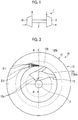
- Fig. 2 is a front view illustrating the centrifugal compressor according to the first embodiment
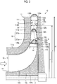
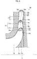
- Fig. 3 is a cross-sectional view illustrating the centrifugal compressor according to the first embodiment
- Fig. 3 illustrates a meridional section including the rotating shaft 3 along line A-A of Fig. 2 (hereinafter, simply referred to as "meridional section").
- the centrifugal compressor 10 according to the first embodiment is provided with a casing 11, an impeller 12, and a diffuser 13.
- the centrifugal compressor 10 is formed in an axisymmetric structure that has the rotating shaft 3 as the center of the axisymmetric structure.
- the casing 11 has a shroud 111 and a hub 112.
- the shroud 111 has a tubular portion 111a extending in the axial direction of the rotating shaft 3 (hereinafter, simply referred to as "axial direction”) and a disk-shaped portion 111b extending in the radial direction of the rotating shaft 3 of the tubular portion 111a (hereinafter, simply referred to as "radial direction").
- the tubular portion 111a forms a suction passage 14 along the axial direction.
- the disk-shaped portion 111b extends radially outward substantially along a direction orthogonal to the rotating shaft 3 after extending while curving radially outward from the tubular portion 111a.
- the hub 112 is an annular disk disposed so as to oppose the disk-shaped portion 111b of the shroud 111.
- the hub 112 rotatably supports the rotating shaft 3.
- the impeller 12 has an impeller hub 12a integrally attached to the rotating shaft 3 and a plurality of blades 12b provided at equal intervals on the outer periphery of the impeller hub 12a.
- the outer periphery of the impeller 12 is covered with the curved part of the disk-shaped portion 111b and the tubular portion 111a of the shroud 111 except for an impeller outlet 12c, which is the position of the peripheral edge of the blade 12b.
- the impeller 12 is capable of taking in a fluid via the suction passage 14 of the shroud 111. As illustrated in Fig.
- the impeller hub 12a has a back plate portion 121a as a part of the outer peripheral surface of the impeller hub 12a to which the blade 12 is attached, the back plate portion 121a extends radially outward, and the back plate portion 121a includes a linear portion 121b extending to the impeller outlet 12c in the direction orthogonal to the rotating shaft 3.
- the diffuser 13 is a vaneless diffuser.
- the diffuser 13 is disposed on the downstream side of the impeller 12.
- the diffuser 13 is an annular space formed by the hub 112 and the disk-shaped portion 111b of the shroud 111 and communicating with the impeller outlet 12c.
- the diffuser 13 has a shroud wall surface 131 formed by a part of the disk-shaped portion 111b of the shroud 111 and a hub wall surface 132 formed by the hub 112.
- the shroud wall surface 131 is a part of the inner wall surface of the disk-shaped portion 111b and extends radially outward radially outside the impeller outlet 12 c.
- the hub wall surface 132 is a part of the inner wall surface of the hub 112 and extends radially outward, while opposing the shroud wall surface 131, radially outside the impeller outlet 12 c.
- the hub wall surface 132 has a gap between the hub wall surface 132 and the shroud wall surface 131.
- An annular diffuser flow path 130 is formed by the gap between the shroud wall surface 131 and the hub wall surface 132. A fluid discharged from the impeller outlet 12c flows through the diffuser flow path 130.
- the impeller 12 rotates and a fluid is suctioned into the casing 11 through the suction passage 14. After the suctioning into the casing 11, the fluid is boosted during passage through the impeller 12 rotating about the rotating shaft 3. Subsequently, the fluid is discharged from the impeller outlet 12c toward the diffuser 13. The fluid discharged from the impeller outlet 12c toward the diffuser 13 flows radially outward as indicated by the solid-line arrows in Fig. 3 while turning in the circumferential direction of the rotating shaft 3 (hereinafter, simply referred to as "circumferential direction") in the diffuser flow path 130 as indicated by a two-dot chain line in Fig. 2 .
- the fluid is decelerated by the frictional force of the shroud wall surface 131 and the hub wall surface 132.
- the flow velocity of the fluid in the turning direction is decreased as the radius of the diffuser flow path 130 (hereinafter, simply referred to as "radius") increases from the rotating shaft 3.
- the fluid is decelerated with an increase in the cross-sectional area of the diffuser flow path 130.
- the fluid undergoes dynamic-to-static pressure conversion while passing through the diffuser 13 and the static pressure rises (recovers).
- the centrifugal compressor 10 supplies the internal combustion engine (not illustrated) with the fluid boosted in this manner.
- a mechanism such as a scroll may be provided in the outer peripheral portion of the diffuser 13.
- the shroud wall surface 131 of the diffuser 13 has an asymptotic portion 131a asymptotic toward the hub wall surface 132 side radially outward from an inlet 130a of the diffuser flow path 130 and a linear portion 131b extending in the direction orthogonal to the rotating shaft 3 from the asymptotic portion 131a to an outlet 130b of the diffuser flow path 130.
- the hub wall surface 132 of the diffuser 13 has a first linear portion 132a extending in the direction orthogonal to the rotating shaft 3 radially outward from the inlet 130a of the diffuser flow path 130, a hub-side convex portion 132b extending radially outward from the first linear portion 132a, and a second linear portion 132c extending in the direction orthogonal to the rotating shaft 3 from the hub-side convex portion 132b to the outlet 130b of the diffuser flow path 130.
- a straight line connecting a starting end 132s of the hub wall surface 132 on the inlet 130a side of the diffuser flow path 130 and a terminating end 132e of the hub wall surface 132 on the outlet 130b side of the diffuser flow path 130 is defined as a straight line L1.
- the straight line L1 is the same direction as the direction orthogonal to the rotating shaft 3 and the first linear portion 132a and the second linear portion 132c of the hub wall surface 132 extend along the straight line L1.
- the hub-side convex portion 132b is a part that protrudes toward the shroud wall surface 131 side relative to the straight line L1 connecting the starting end 132s and the terminating end 132e of the hub wall surface 132.
- the centrifugal compressor 10 is formed in an axisymmetric structure having the rotating shaft 3 as the center of the axisymmetric structure, and thus the hub-side convex portion 132b is formed over the entire periphery of the hub wall surface 132.
- the hub-side convex portion 132b is formed in the shape of a smooth curve that has a curvature continuously changing between the first linear portion 132a and the second linear portion 132c.
- the hub-side convex portion 132b extends, while approaching the shroud wall surface 131 side, radially outward from an innermost peripheral portion 132i on the first linear portion 132a side and approaches the shroud wall surface 131 most at a vertex 132t.
- the hub-side convex portion 132b extends away from the shroud wall surface 131 radially outward from the vertex 132t to an outermost peripheral portion 1320 on the second linear portion 132c side.
- the innermost peripheral portion 132i of the hub-side convex portion 132b is provided radially outside the starting end 132s and the outermost peripheral portion 1320 of the hub-side convex portion 132b is provided radially inside the terminating end 132e.
- the outermost peripheral portion 1320 of the hub-side convex portion 132b is provided radially inside the position that has a radius of 0.9 times or less an outlet radius r2 at the outlet 130b of the diffuser flow path 130.
- the hub-side convex portion 132b is provided radially inside the position that has a radius of 0.9 times or less the outlet radius r2.
- the vertex 132t of the hub-side convex portion 132b is provided in the range that is radially inward from the central portion of the hub-side convex portion 132b in the radial direction, that is, the intermediate position between the innermost peripheral portion 132i and the outermost peripheral portion 1320 in the radial direction.
- the vertex 132t of the hub-side convex portion 132b is formed at the radial position that is 1.1 times or more and 1.4 times or less an inlet radius r1 at the inlet 130a of the diffuser flow path 130. More preferably, the vertex 132t of the hub-side convex portion 132b is formed at the radial position that is 1.05 times or more and 1.4 times or less the inlet radius r1.
- the vertex 132t is formed at the radial position that is 1.1 times or more and 1.2 times or less the inlet radius r1. In a case where the value that is obtained by the inlet width b1 of the diffuser flow path 130 at the inlet 130a being divided by the inlet radius r1 is approximately 0.2, it is preferable that the vertex 132t is formed at the radial position that is 1.3 times or more and 1.4 times or less the inlet radius r1.
- a distance D from the straight line L1 to the vertex 132t in the axial direction is 0.1 times or more and 0.3 times or less an outlet width b2 of the diffuser flow path 130 at the outlet 130b.
- the inlet width b1 and the inlet radius r1 of the diffuser flow path 130 at the inlet 130a and a width b and a radius r of the diffuser flow path 130 at any radial position in the range where the hub-side convex portion 132b is formed satisfy the relationship of the following Equation (1).
- the left side in Equation (1) represents the annular area that is the product of circumferential length "2 ⁇ r” and the width b of the diffuser flow path 130 at any radial position.
- the right side in Equation (1) represents the annular area that is the product of circumferential length "2 ⁇ r1" and the width b1 of the diffuser flow path 130 at the inlet 130a.
- the hub-side convex portion 132b is formed so as to have a size at which the annular area that is the product of circumferential length "2 ⁇ r" and the width b of the diffuser flow path 130 at any radial position increases as compared with the annular area that is the product of circumferential length "2 ⁇ r1" and the width b1 of the diffuser flow path 130 at the inlet 130a.
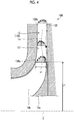
- Fig. 4 is a cross-sectional view illustrating a centrifugal compressor as the comparative example.
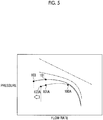
- Fig. 5 is an explanatory diagram illustrating an example of the flow rate-pressure characteristics of the centrifugal compressor according to the first embodiment and an example of the flow rate-pressure characteristics of the centrifugal compressor as the comparative example.
- the solid line in Fig. 5 is an example of the flow rate-pressure characteristics of the centrifugal compressor 10 according to the first embodiment
- the dashed line in Fig. 5 is an example of the flow rate-pressure characteristics of a centrifugal compressor 10A as the comparative example.
- the two-dot chain line in Fig. 5 indicates ideal flow rate-pressure characteristics in a case where it is assumed that there is no pressure loss in the impeller 12 and the diffuser 13 and the one-dot chain line in Fig. 5 indicates the flow rate-pressure characteristics in a case where it is assumed that there is no pressure loss in the diffuser 13 with the pressure loss in the impeller 12 taken into account.
- the solid-line arrows in Fig. 4 indicate the radial component of the flow velocity in the diffuser flow path 130 at a time when the centrifugal compressor 10A operates at a low flow operation point 101A (see Fig. 5 ), which is lower in flow rate than a normal operation point 100A (see Fig. 5 ) near the maximum efficiency point.
- a flow angle ⁇ 2 in the turning direction decreases by approximately 2/3 to 1/2 from a flow angle ⁇ 1 in the case of the normal operation point 100A as illustrated in, for example, Fig. 2 when the centrifugal compressor 10A operates at the low flow operation point 101A.
- the hub wall surface 132 of the diffuser 13 of the centrifugal compressor 10A as the comparative example does not have the hub-side convex portion 132b.
- the hub wall surface 132 of the diffuser 13 extends perpendicularly in the radial direction along the direction orthogonal to the rotating shaft 3.
- the other constituent elements of the centrifugal compressor 10A and the size and the like of each constituent element are similar to those of the centrifugal compressor 10, and thus will not be described.
- the flow of the fluid in the diffuser flow path 130 will be described first with reference to Fig. 4 regarding the centrifugal compressor 10A as the comparative example.
- the radial component of the flow velocity of the fluid that has flowed into the diffuser flow path 130 has a boundary layer in the vicinity of the shroud wall surface 131 and the hub wall surface 132.
- the force with which the flow heads toward the downstream side in the axial direction (right side in Fig 4 , hereinafter, simply referred to as "axially downstream side") after passing through the impeller 12 remains, and thus the boundary layer on the hub wall surface 132 side becomes thin and the boundary layer on the shroud wall surface 131 side becomes thick.
- the boundary layer on the shroud wall surface 131 side and the boundary layer on the hub wall surface 132 side gradually become uniform as the flow in the diffuser flow path 130 heads toward the outlet 130b side in a case where the centrifugal compressor 10A operates at the flow rate at the normal operation point 100A.
- a reverse flow may occur at the boundary layer of the flow on the hub wall surface 132 side as illustrated in Fig. 4 in a case where the centrifugal compressor 10A operates at the flow rate at the low flow operation point 101A.
- the circumferential component of the flow velocity is smaller (that is, the centrifugal force of the flow is smaller) on the hub wall surface 132 side than on the shroud wall surface 131 side and it may become impossible to resist the radially inward force acting on the fluid in the diffuser flow path 130, where the static pressure of the fluid increases as the radius increases.
- the range that is closer to the hub wall surface 132 side than the line indicated by the two-dot chain line is a reverse flow region where the reverse flow has occurred.
- the reverse flow region is usually generated from the radial position that is 1.1 times or more and 1.2 times or less the inlet radius r1 in a case where the value that is obtained by the inlet width b1 of the diffuser flow path 130 at the inlet 130a being divided by the inlet radius r1 of the inlet 130a is approximately 0.05.
- the reverse flow region is usually generated from the radial position that is 1.1 times or more and 1.2 times or less the inlet radius r1 in a case where the value that is obtained by the inlet width b1 of the diffuser flow path 130 at the inlet 130a being divided by the inlet radius r1 is approximately 0.2.
- the reverse flow region is usually generated from the radial position that is 1.1 times or more and 1.4 times or less the inlet radius r1 of the inlet 130a of the diffuser flow path 130.
- a flow center line Lc center line of flow rate bisection in the width direction of the diffuser flow path 130 moves toward the shroud wall surface 131 side in the vicinity of the reverse flow region as the center line Lc heads radially outward from the inlet 130a. Then, the flow rate in the vicinity of the shroud wall surface 131 relatively increases, and thus no reverse flow is likely to occur at the boundary layer on the shroud wall surface 131 side. Subsequently, the center line Lc of the flow heading toward the outlet 130b from the vicinity of the reverse flow region gradually moves toward the hub wall surface 132 side, and thus the center line Lc draws an S shape as a whole.
- the reverse flow region at the boundary layer on the hub wall surface 132 side expands in a case where the centrifugal compressor 10A is operated with the flow rate further reduced from the example that is illustrated in Fig. 4 .
- a flow with a small turning-direction energy flows from the outlet 130b into the diffuser flow path 130 (reverse flow region).
- the reverse flow region expands over the entire width of the diffuser flow path 130 in the vicinity of the outlet 130b, boosting of the fluid by the diffuser 13 becomes impossible, and a stall (surge) of the diffuser 13 occurs.
- the flow rate at which the stall of the diffuser 13 occurs is defined as a surge point 103A in Fig. 5 .
- the width of the diffuser flow path 130 is substantially narrowed by the reverse flow region. Then, it may be impossible to sufficiently reduce the flow velocity.
- the pressure loss at the diffuser 13 increases due to the reverse flow.
- the static pressure of the fluid cannot be sufficiently raised by the diffuser 13, which leads to a decline in the efficiency of the centrifugal compressor 10A and, in turn, a decline in the efficiency of the turbocharger 1.
- the expansion of the reverse flow occurring in the diffuser flow path 130 leads to a stall (surge) of the diffuser 13 as described above.
- the hub wall surface 132 of the diffuser 13 of the centrifugal compressor 10 has the hub-side convex portion 132b.
- the hub-side convex portion 132b is formed in a reverse flow-prone region at the boundary layer on the hub wall surface 132 side. Accordingly, the region on the hub wall surface 132 side where a reverse flow is likely to occur in the diffuser flow path 130 during operation at a low flow rate in particular is closed in advance by the hub-side convex portion 132b.
- the boundary layer of the flow on the hub wall surface 132 side in the vicinity of the hub-side convex portion 132b becomes thinner than in the centrifugal compressor 10A of the comparative example by the hub-side convex portion 132b. Narrowed as a result is the range in which a fluid having a low circumferential flow velocity and a small centrifugal force is incapable of resisting the radially inward force that acts on the fluid in the diffuser flow path 130. Further, since the width of the diffuser flow path 130 is narrowed by the hub-side convex portion 132b, the main flow velocity in the diffuser flow path 130 becomes higher than in the centrifugal compressor 10A of the comparative example.
- the static pressure of the fluid can be sufficiently raised, as illustrated in Fig. 5 , by the diffuser 13 even during operation at a low flow rate as compared with the centrifugal compressor 10A of the comparative example and it is possible to improve the efficiency of the centrifugal compressor 10 and, in turn, the efficiency of the turbocharger 1.
- a stall of the diffuser 13 attributable to a reverse flow can be prevented as a result of the reverse flow prevention on the hub wall surface 132 side.
- the reverse flow region expands up to the outlet 130b of the diffuser flow path 130 and a stall of the diffuser 13 occurs once a reverse flow occurs at the low flow operation point 101A illustrated in Fig. 5 and the flow rate decreases to the surge point 103A.
- a reverse flow begins to occur when the flow rate has further decreased as compared with the low flow operation point 101, which is equal in flow rate to the low flow operation point 101A, and a stall of the diffuser 13 occurs when the flow rate has decreased to a surge point 103 illustrated in Fig. 5 .
- a reverse flow is less likely to occur and the reverse flow region is less likely to expand, even when the operation point is changed to a lower flow rate side, than in the centrifugal compressor 10A of the comparative example by the hub wall surface 132 being provided with the hub-side convex portion 132b.
- the flow rate at the surge point 103 at which a stall of the diffuser 13 occurs can be lower than the flow rate at the surge point 103A. Accordingly, the surge margin of the centrifugal compressor 10 can be expanded and the centrifugal compressor 10 can be operated at a lower flow rate.
- the centrifugal compressor 10 and the turbocharger 1 according to the first embodiment it is possible to prevent a reverse flow from occurring on the hub wall surface 132 side forming the diffuser flow path 130, the efficiency of the centrifugal compressor 10 can be improved, the efficiency of the turbocharger 1 can be improved, and the surge margin of the centrifugal compressor 10 can be expanded.
- the vertex 132t of the hub-side convex portion 132b is provided in the range that is radially inward from the central portion of the hub-side convex portion 132b in the radial direction, that is, the intermediate position between the innermost peripheral portion 132i and the outermost peripheral portion 1320 in the radial direction.
- the vertex 132t of the hub-side convex portion 132b can be brought close to the inlet 130a side of the diffuser flow path 130, and thus it is possible to satisfactorily prevent a reverse flow on the hub wall surface 132 side that is likely to occur at the front half part of the diffuser flow path 130 on the inlet 130a side.
- the vertex 132t of the hub-side convex portion 132b is formed at the radial position that is 1.05 times or more and 1.4 times or less the inlet radius r1 at the inlet 130a of the diffuser flow path 130.
- the hub-side convex portion 132b is provided radially inside the radial position that is 0.9 times or less the outlet radius r2 at the outlet 130b of the diffuser flow path 130.
- the distance D from the straight line L1 to the vertex 132t in the axial direction ranges from 0.1 times to 0.3 times the outlet width b2 of the diffuser flow path 130 at the outlet 130b.
- the hub-side convex portion 132b is formed so as to have a size at which the annular area that is the product of circumferential length "2 ⁇ r" and the width b of the diffuser flow path 130 at any radial position increases as compared with the annular area that is the product of circumferential length "2 ⁇ r1" and the width b1 of the diffuser flow path 130 at the inlet 130a.
- the shroud wall surface 131 has the asymptotic portion 131a asymptotic to the hub wall surface 132 side radially outward from the inlet 130a.
- the width of the diffuser flow path 130 in the vicinity of the inlet 130a can be narrowed by the asymptotic portion 131a of the shroud wall surface 131, and thus the boundary layer of the flow on the shroud wall surface 131 side, which is likely to become thick in the vicinity of the inlet 130a, can be reduced in thickness.
- the thickness of the boundary layer of the flow on the shroud wall surface 131 side and the thickness of the boundary layer of the flow on the hub wall surface 132 side can become uniform in the vicinity of the inlet 130a of the diffuser flow path 130 and the flow can be pushed out toward the hub wall surface 132 side as a whole.
- the boundary layer of the flow on the hub wall surface 132 side can be further reduced in thickness and it is possible to prevent a reverse flow at the boundary layer of the flow on the hub wall surface 132 side.
- shroud wall surface 131 may not have the asymptotic portion 131a in the first embodiment. In other words, the shroud wall surface 131 may have only a linear portion extending radially outward in the direction orthogonal to the rotating shaft 3.
- Fig. 6 is a cross-sectional view illustrating a centrifugal compressor according to a modification example of the first embodiment.
- the linear portion 131b of the shroud wall surface 131 extends obliquely to the axially downstream side radially outward from the asymptotic portion 131a.
- the second linear portion 132c of the hub wall surface 132 extends obliquely to the axially downstream side radially outward from the hub-side convex portion 132b.
- the inclination angle of the linear portion 131b of the shroud wall surface 131 and the inclination angle of the second linear portion 132c of the hub wall surface 132 are substantially equal to each other.
- the inclination angle of the linear portion 131b of the shroud wall surface 131 and the inclination angle of the second linear portion 132c of the hub wall surface 132 are approximately five degrees to 10 degrees relative to the direction orthogonal to the rotating shaft 3.
- Fig. 7 is a cross-sectional view illustrating a centrifugal compressor according to another modification example of the first embodiment.
- the first linear portion 132a and the hub-side convex portion 132b of the hub wall surface 132 may be inclined at the same angle as the second linear portion 132c as in a centrifugal compressor 10C illustrated in Fig. 7 .
- the hub wall surface 132 may extend obliquely toward the axially downstream side from the starting end 132s toward the terminating end 132e.
- the inclination angle of the linear portion 131b of the shroud wall surface 131 and the inclination angle of the hub wall surface 132 are substantially equal to each other and the angles are approximately five degrees to 10 degrees relative to the direction orthogonal to the rotating shaft 3.
- the hub wall surface 132 inclined toward the axially downstream side from the starting end 132s toward the terminating end 132e is capable of smoothly guiding, into the diffuser flow path 130, a flow in which a force toward the axially downstream side remains in the vicinity of the inlet 130a of the diffuser flow path 130, that is, the impeller outlet 12c.
- the shroud wall surface 131 has the asymptotic portion 131a as described above.
- the shroud wall surface 131 having the asymptotic portion 131a is another reason why it is possible to smoothly guide, into the diffuser flow path 130, the flow in which the force toward the axially downstream side remains in the vicinity of the inlet 130a of the diffuser flow path 130, that is, the impeller outlet 12c.
- a pressure loss at the inlet 130a of the diffuser flow path 130 can be prevented, the rate of static pressure recovery by the diffuser 13 can be further increased, and the efficiency of the centrifugal compressor 10C and the efficiency of the turbocharger 1 can be further improved.
- FIG. 8 is a cross-sectional view illustrating the centrifugal compressor according to the second embodiment.
- the centrifugal compressor 20 according to the second embodiment is provided with a diffuser 23 in place of the diffuser 13 of the centrifugal compressor 10 according to the first embodiment.
- the diffuser 23 has a shroud wall surface 231 in place of the shroud wall surface 131 of the diffuser 13 of the centrifugal compressor 10 according to the first embodiment.
- the other configurations of the centrifugal compressor 20 and the diffuser 23 are similar to those of the centrifugal compressor 10 and the diffuser 13, and thus will not be described. It should be noted that the centrifugal compressor 20 according to the second embodiment is also applied to the turbocharger 1 described in the first embodiment.
- the shroud wall surface 231 has an asymptotic portion 231a asymptotic toward the hub wall surface 132 radially outward from the inlet 130a of the diffuser flow path 130, a shroud-side concave portion 231b extending radially outward from the asymptotic portion 231a, and a linear portion 231c extending in the direction orthogonal to the rotating shaft 3 from the shroud-side concave portion 231b to the outlet 130b of the diffuser flow path 130.
- the outermost peripheral portion of the asymptotic portion 231a of the shroud wall surface 231 and the innermost peripheral portion of the linear portion 231c are formed side by side in the axial direction.
- the shroud-side concave portion 231b is a part concave to the side that is opposite to the hub wall surface 132 (left side in Fig. 8 ) beyond a straight line L2 connecting the outermost peripheral portion of the asymptotic portion 231a and the innermost peripheral portion of the linear portion 231c.
- the shroud-side concave portion 231b is formed over the entire periphery of the shroud wall surface 231.
- the shroud-side concave portion 231b is formed in the shape of a smooth curve that has a curvature continuously changing between the asymptotic portion 231a and the linear portion 231c. As illustrated in Fig. 8 , the shroud-side concave portion 231b is provided at a position opposing the hub-side convex portion 132b.
- the shroud-side concave portion 231b is formed so as to have a size at which the width of the diffuser flow path 130 becomes constant between the shroud-side concave portion 231b and the hub-side convex portion 132b as a limit.
- the shroud-side concave portion 231b is concave toward the side that is opposite to the hub wall surface 132 in a shape conforming to the shape of the hub-side convex portion 132b with the shroud-side concave portion 231b having the same radial starting end as the innermost peripheral portion 132i of the hub-side convex portion 132b and having the same radial terminating end as the outermost peripheral portion 1320 of the hub-side convex portion 132b.
- the shroud-side concave portion 231b is formed so as to have a size at which the width of the diffuser flow path 130 becomes constant between the shroud-side concave portion 231b and the hub-side convex portion 132b as a limit.
- the shroud-side concave portion 231b may not have exactly the same radial starting end as the innermost peripheral portion 132i of the hub-side convex portion 132b and may not have exactly the same radial terminating end as the outermost peripheral portion 1320 of the hub-side convex portion 132b insofar as the shroud-side concave portion 231b opposes the hub-side convex portion 132b.
- the shroud-side concave portion 231b may not be concave toward the side opposite to the hub wall surface 132 in the shape that conforms to the shape of the hub-side convex portion 132b.
- the shroud-side concave portion 231b may not be formed so as to have the size at which the width of the diffuser flow path 130 becomes constant between the shroud-side concave portion 231b and the hub-side convex portion 132b as a limit.
- the linear portion 231c of the shroud wall surface 231 and the second linear portion 132c of the hub wall surface 132 may be inclined radially outward to the axially downstream side as in the centrifugal compressor 10B according to the modification example of the first embodiment.
- the shroud wall surface 231 may not have the asymptotic portion 231a.
- the shroud wall surface 231 may have a linear portion extending radially outward in the direction orthogonal to the rotating shaft 3, the linear portion 231c, and the shroud-side concave portion 231b concave toward the side opposite to the hub wall surface 132 between the linear portion 231c and the linear portion.
- FIG. 9 is a cross-sectional view illustrating the centrifugal compressor according to the third embodiment.
- the centrifugal compressor 30 according to the third embodiment is provided with an impeller 32 in place of the impeller 12 of the centrifugal compressor 10 according to the first embodiment.
- the centrifugal compressor 30 according to the third embodiment is provided with a diffuser 33 in place of the diffuser 13 of the centrifugal compressor 10 according to the first embodiment.
- the other configurations of the centrifugal compressor 30 are similar to those of the centrifugal compressor 10, and thus will not be described. It should be noted that the centrifugal compressor 30 according to the third embodiment is also applied to the turbocharger 1 described in the first embodiment.
- the impeller 32 has an impeller hub 32a rotating integrally with the rotating shaft 3 and a plurality of blades 32b attached to the impeller hub 32a.
- the blade 32b is attached to the outer peripheral surface of the impeller hub 32a.
- a back plate portion 321a which is a part of the outer peripheral surface and extends radially outward, includes an inclined portion 321b extending obliquely toward the axially downstream side and a hub wall surface 332.
- the inclined portion 321b is inclined at an inclination angle ⁇ 1 relative to the direction orthogonal to the rotating shaft 3 at the impeller outlet 12 c.
- the impeller 32 is referred to as a back plate-inclined impeller.
- the diffuser 33 has the hub wall surface 332 in place of the hub wall surface 132 of the diffuser 13.
- the hub wall surface 332 has a hub-side concave portion 332a in place of the first linear portion 132a of the hub wall surface 132.
- the other configurations of the diffuser 33 and the hub wall surface 332 are similar to those of the diffuser 13 and the hub wall surface 132, and thus will not be described.
- the hub-side concave portion 332a extends radially outward from the inlet 130a of the diffuser flow path 130 and is connected to the innermost peripheral portion 132i of the hub-side convex portion 132b.
- the hub-side concave portion 332a is a part concave toward the side that is opposite to the shroud wall surface 131 relative to the straight line L1 connecting the terminating end 132e and the starting end 132s of the hub wall surface 332.
- the hub-side concave portion 332a is formed over the entire periphery of the hub wall surface 332.
- the hub-side concave portion 332a is formed in the shape of a smooth curve that has a curvature continuously changing between the hub-side convex portion 132b and the starting end 132s of the hub wall surface 332.
- the hub-side concave portion 332a is concave toward the side opposite to the shroud wall surface 131 at an inclination angle conforming to the inclination angle ⁇ 1 of the back plate portion 321a of the impeller hub 32a.
- the part of the hub-side concave portion 332a that extends away from the shroud wall surface 131 radially outward from the starting end 132s is inclined with respect to the direction orthogonal to the rotating shaft 3 at the angle that is equal to the inclination angle ⁇ 1.
- the back plate portion 321a of the impeller hub 32a is inclined at the inclination angle ⁇ 1 at the impeller outlet 12c and the hub-side concave portion 332a formed at an inclination angle conforming to the inclination angle ⁇ 1 of the impeller hub 32a is capable of smoothly guiding the flow into the diffuser flow path 130 even in a case where the force toward the downstream side in the axial direction of the flow becomes stronger in the vicinity of the inlet 130a of the diffuser flow path 130.
- the inclination angle of the hub-side concave portion 332a may not be exactly the same as the inclination angle ⁇ 1 and the inclination angle of the hub-side concave portion 332a may be smaller or larger in value than the inclination angle ⁇ 1 insofar as a fluid can be smoothly guided into the diffuser flow path 130 from the impeller hub 32a.
- the shroud wall surface 131 has the asymptotic portion 131a, which is asymptotic to the hub wall surface 332 side radially outward from the inlet 130a of the diffuser flow path 130, as in the first and second embodiments. Accordingly, an excessive increase in the width of the diffuser flow path 130 in the vicinity of the inlet 130a can be prevented by the asymptotic portion 131a of the shroud wall surface 131 even with the hub-side concave portion 332a formed in the hub wall surface 332.
- the thickness of the boundary layer of the flow on the shroud wall surface 131 side and the thickness of the boundary layer of the flow on the hub wall surface 332 side can become uniform in the vicinity of the inlet 130a of the diffuser flow path 130 and the flow can be pushed out toward the hub wall surface 332 side as a whole.
- an increase in the thickness of the boundary layer of the flow on the hub wall surface 332 side can be prevented even in a case where the hub wall surface 332 is provided with the hub-side concave portion 332a, and thus it is possible to prevent a reverse flow at the boundary layer of the flow on the hub wall surface 332 side.
- the shroud wall surface 131 may not have the asymptotic portion 131a in the third embodiment.
- the shroud wall surface 131 may have only a linear portion extending radially outward in the direction orthogonal to the rotating shaft 3.
- the asymptotic portion 131a may be formed in the shape of a convex portion that is closer to the hub wall surface 332 side than in the example illustrated in Fig. 9 .
- the linear portion 131b of the shroud wall surface 131 and the second linear portion 132c of the hub wall surface 332 may be inclined radially outward to the axially downstream side as in the centrifugal compressor 10B according to the modification example of the first embodiment.
- FIG. 10 is a cross-sectional view illustrating the centrifugal compressor according to the fourth embodiment.
- the centrifugal compressor 40 according to the fourth embodiment is provided with the impeller 32 of the third embodiment in place of the impeller 12 of the centrifugal compressor 10 according to the first embodiment.
- the centrifugal compressor 40 according to the fourth embodiment is provided with a diffuser 43 in place of the diffuser 13 of the centrifugal compressor 10 according to the first embodiment.
- the other configurations of the centrifugal compressor 40 are similar to those of the centrifugal compressor 10, and thus will not be described. It should be noted that the centrifugal compressor 40 according to the fourth embodiment is also applied to the turbocharger 1 described in the first embodiment.
- the diffuser 43 has the shroud wall surface 231 of the diffuser 23 of the second embodiment in place of the shroud wall surface 131 of the diffuser 13 of the first embodiment.
- the diffuser 43 has the hub wall surface 332 of the diffuser 33 of the third embodiment in place of the hub wall surface 132 of the diffuser 13 of the first embodiment.
- the diffuser 43 has the shroud wall surface 231 of the second embodiment and the hub wall surface 332 of the third embodiment. Accordingly, the centrifugal compressor 40 according to the fourth embodiment is capable of achieving the effects of both the centrifugal compressor 20 according to the second embodiment and the centrifugal compressor 30 according to the third embodiment.
- the linear portion 231c of the shroud wall surface 231 and the second linear portion 132c of the hub wall surface 332 may be inclined radially outward to the axially downstream side as in the centrifugal compressor 10B according to the modification example of the first embodiment.
- the shroud wall surface 231 may not have the asymptotic portion 231a in the fourth embodiment.
- the shroud wall surface 231 may have a linear portion extending radially outward in the direction orthogonal to the rotating shaft 3, the linear portion 231c, and the shroud-side concave portion 231b concave toward the side opposite to the hub wall surface 332 between the linear portion 231c and the linear portion.
- the asymptotic portion 231a may be formed in the shape of a convex portion that is closer to the hub wall surface 332 side than in the example illustrated in Fig. 10 .
- the hub-side convex portion 132b is formed in the shape of a smooth curve that has a curvature continuously changing between the second linear portion 132c and the first linear portion 132a or the hub-side concave portion 332a in the first to fourth embodiments, the shape of the hub-side convex portion 132b is not limited thereto.
- the hub-side convex portion 132b may have, for example, a circular arc shape or a parabolic shape.
- the hub-side convex portion 132b may include a linear part at a part of the hub-side convex portion 132b.
- the hub-side convex portion 132b may be connected to the first linear portion 132a or the hub-side concave portion 332a in the shape of a smooth curve or while being refracted.
- the hub-side convex portion 132b may be connected to the second linear portion 132c in the shape of a smooth curve or while being refracted.
- a linear portion extending in the axial direction may be included between the second linear portion 132c and the outermost peripheral portion 1320 of the hub-side convex portion 132b.
- the hub-side convex portion 132b may be formed from the starting end 132s of the hub wall surface 132 at the inlet 130a of the diffuser flow path 130 or may be formed from the terminating end 132e of the hub wall surface 132 at the outlet 130b of the diffuser flow path 130.
- the innermost peripheral portion 132i of the hub-side convex portion 132b may coincide with the starting end 132s and the outermost peripheral portion 1320 of the hub-side convex portion 132b may coincide with the terminating end 132e.
- the present invention is applied to a vaneless diffuser in the first to fourth embodiments
- the present invention may also be applied to a so-called small-chord ratio diffuser in which a vane (blade) is disposed in the range of up to approximately 1/2 of the radius gap from the inlet 130a to the outlet 130b in the radial direction from the inlet 130a of the diffuser flow path 130.
- the present invention may be applied to a so-called vaned diffuser in which a vane (blade) is disposed in the range of approximately 80% to 90% of the radius gap from the inlet 130a to the outlet 130b in the diffuser flow path 130.
Abstract
Description
- The present invention relates to a centrifugal compressor and a turbocharger.
- Known in the related art are techniques relating to a centrifugal compressor and a turbocharger provided with the centrifugal compressor boosting a fluid by impeller rotation and compressing the boosted fluid by decelerating the fluid with a diffuser and performing dynamic-to-static pressure conversion. For example, PTL 1 discloses a structure in which a diffuser surface disposed on the axially upstream side of an impeller is divided into a converging section and a diverging section in a compressor impeller housing for a turbocharger compressor impeller. In this structure, the diverging section reduces wall friction while the converging section forms a uniform flow so that the flow can be stabilized and the efficiency of the diffuser can be improved.
- [PTL 1] PCT Japanese Translation Patent Publication No.
2008-510100 - In the diffuser of the centrifugal compressor according to the related art, a reverse flow may occur at the boundary layer of the flow on a hub wall surface side, which is a part of the wall surface that forms a diffuser flow path and is disposed on the axially downstream side. This is because the circumferential velocity of the flow is lower (that is, the centrifugal force of the flow is smaller) on the hub wall surface side than on a shroud wall surface side disposed on the axially upstream side and it may become impossible to resist the force that acts radially inward relative to the fluid in the diffuser flow path. The reverse flow is likely to occur at a low flow rate in particular.
- Once a reverse flow occurs on the hub wall surface side in the diffuser flow path, the width of the diffuser flow path is substantially narrowed by the reverse flow region. Then, it may be impossible to sufficiently reduce the flow velocity. In addition, the pressure loss at the diffuser increases due to the reverse flow. As a result, the static pressure of the fluid cannot be sufficiently raised by the diffuser, which leads to a decline in the efficiency of the centrifugal compressor and, in turn, a decline in the efficiency of the turbocharger. In addition, expansion of the reverse flow occurring in the diffuser flow path leads to a stall (surge) of the diffuser. Accordingly, it is necessary to maintain a flow rate at which no stall occurs, which is an obstacle to the industrial demand of surge margin expansion. The surge margin is the difference between the flow rate at the maximum efficiency point and the flow rate at the stall-occurring surge point.
- The present invention has been made in view of the above, and an object of the present invention is to prevent a reverse flow from occurring on a hub wall surface side forming a diffuser flow path, improve the efficiency of a centrifugal compressor, improve the efficiency of a turbocharger provided with the centrifugal compressor, and expand the surge margin of the centrifugal compressor.
- In order to solve the problems mentioned above and achieve the purpose, the present invention provides a centrifugal compressor including an impeller boosting a fluid by rotation about a rotating shaft and a diffuser converting a dynamic pressure of a fluid boosted by the impeller into a static pressure, in which the diffuser has a shroud wall surface extending in a radial direction of the rotating shaft and a hub wall surface extending in the radial direction and opposing the shroud wall surface on a downstream side of a flow in an axial direction of the rotating shaft, having a gap between the hub wall surface and the shroud wall surface, and forming an annular diffuser flow path with the gap, the fluid flowing through the diffuser flow path, and a hub-side convex portion is formed over an entire periphery of the hub wall surface, the hub-side convex portion protruding toward the shroud wall surface side relative to a straight line connecting a starting end on an inlet side of the diffuser flow path and a terminating end on an outlet side of the diffuser flow path.
- In this configuration, the region on the hub wall surface side where a reverse flow is likely to occur in the diffuser flow path during operation at a low flow rate in particular can be closed in advance by the hub-side convex portion. In addition, the boundary layer of the flow on the hub wall surface side can be reduced in thickness by the hub-side convex portion, and thus it is possible to narrow the range in which a fluid having a low circumferential flow velocity and a small centrifugal force is incapable of resisting the radially inward force that acts on the fluid in the diffuser flow path. Further, since the width of the diffuser flow path is narrowed by the hub-side convex portion, the main flow velocity in the diffuser flow path can be increased. As a result, a reverse flow can be prevented from occurring at the boundary layer of the flow on the hub wall surface side in the diffuser flow path. As a result, the static pressure can be sufficiently raised by the diffuser. In addition, a stall of the diffuser attributable to a reverse flow can be prevented, and thus the flow rate at a surge point can be reduced and the centrifugal compressor can be operated at a lower flow rate. Accordingly, with the centrifugal compressor according to the present invention, a reverse flow can be prevented from occurring on the hub wall surface side forming the diffuser flow path, the efficiency of the centrifugal compressor can be improved, the efficiency of a turbocharger provided with the centrifugal compressor can be improved, and the surge margin of the centrifugal compressor can be expanded.
- Preferably, a vertex of the hub-side convex portion is provided in a range inward in the radial direction from a central portion of the hub-side convex portion in the radial direction.
- With this configuration, the vertex of the hub-side convex portion can be brought close to the inlet side of the diffuser flow path, and thus it is possible to satisfactorily prevent a reverse flow on the hub wall surface side that is likely to occur at the front half part of the diffuser flow path on the inlet side.
- Preferably, a vertex of the hub-side convex portion is formed at a radial position 1.05 times or more and 1.4 times or less a radius from the rotating shaft at the inlet of the diffuser flow path.
- With this configuration, it is possible to satisfactorily prevent a reverse flow on the hub wall surface side that is likely to occur at the radial position which is 1.05 times to 1.4 times the inlet radius at the inlet of the diffuser flow path.
- Preferably, the hub-side convex portion is provided inside a position in the radial direction, the position having a radius of 0.9 times or less a radius from the rotating shaft at the outlet of the diffuser flow path.
- With this configuration, a reverse flow on the hub wall surface side that is likely to occur at the front half part of the diffuser flow path on the inlet side in the radial direction can be satisfactorily prevented and, at the same time, it is possible to prevent the width of the diffuser flow path from being narrowed in an excessive radius region in the region where the hub-side convex portion reaches the vicinity of the outlet. As a result, it is possible to achieve a sufficient deceleration of the flow by means of the diffuser.
- Preferably, the hub-side convex portion has a distance from the straight line to a vertex in the axial direction ranging from 0.1 times to 0.3 times a width of the diffuser flow path at the outlet.
- With this configuration, it is possible to prevent the diffuser flow path from being excessively narrowed in the width direction by the hub-side convex portion, and thus it is possible to achieve a sufficient deceleration of the flow by means of the diffuser.
- Preferably, the hub-side convex portion is formed so as to have a size at which an annular area as a product of a circumferential length and a width of the diffuser flow path at any radial position increases as compared with an annular area as a product of a circumferential length and a width of the diffuser flow path at the inlet.
- With this configuration, an excessive decrease in the annular area of the diffuser flow path attributable to the hub-side convex portion can be prevented, and thus it is possible to achieve a sufficient deceleration of the flow by means of the diffuser.
- Preferably, the shroud wall surface has a shroud-side concave portion provided so as to oppose the hub-side convex portion and be concave to a side opposite to the hub wall surface.
- With this configuration, an excessive decrease in the width of the diffuser flow path can be prevented by the shroud-side concave portion even with the hub wall surface provided with the hub-side convex portion. Accordingly, it is possible to prevent an excessive increase in the main flow velocity in the diffuser flow path attributable to the provided hub-side convex portion. As a result, a pressure loss attributable to wall surface friction can be prevented and adjustment can be performed in a more appropriate manner such that flow deceleration by the diffuser and, in turn, the rate of recovery of the static pressure of the fluid reaches a desired value.
- Preferably, the shroud-side concave portion is formed so as to have a size at which a width of the diffuser flow path becomes constant between the hub-side convex portion and the shroud-side concave portion as a limit.
- With this configuration, it is possible to prevent an excessive increase in the width of the diffuser flow path between the hub-side convex portion and the shroud-side concave portion and it is possible to prevent the flow from losing uniformity in the diffuser flow path. As a result, it becomes possible to more appropriately adjust the rate of recovery of the static pressure of the fluid by the diffuser.
- Preferably, the impeller has an impeller hub rotating integrally with the rotating shaft and a blade attached to the impeller hub, the impeller hub includes a linear portion extending in a direction orthogonal to the rotating shaft to an impeller outlet, and the hub wall surface forming the diffuser flow path extends obliquely toward the downstream side in the axial direction from the starting end toward the terminating end.
- In this configuration, the hub wall surface inclined toward the axially downstream side from the starting end toward the terminating end is capable of smoothly guiding, into the diffuser flow path, a flow in which a force toward the axially downstream side remains in the vicinity of the inlet of the diffuser flow path, that is, the impeller outlet. As a result, a pressure loss at the inlet of the diffuser flow path can be prevented, the rate of static pressure recovery by the diffuser can be further increased, and the efficiency of the centrifugal compressor and the efficiency of the turbocharger can be further improved.
- Preferably, the impeller has an impeller hub rotating integrally with the rotating shaft and a blade attached to the impeller hub, the impeller hub includes an inclined portion extending obliquely toward the downstream side in the axial direction toward the hub wall surface forming the diffuser flow path, and the hub wall surface forming the diffuser flow path has a hub-side concave portion concave toward a side opposite to the shroud wall surface at an inclination angle conforming to an inclination angle of the impeller hub radially inside the hub-side convex portion.
- In this configuration, impeller hub is inclined at the impeller outlet and the hub-side concave portion formed at an inclination angle conforming to the inclination angle of the impeller hub is capable of smoothly guiding the flow into the diffuser flow path even in a case where the force toward the downstream side in the axial direction of the flow becomes stronger in the vicinity of the inlet of the diffuser flow path. As a result, a pressure loss at the inlet of the diffuser flow path can be prevented, the rate of static pressure recovery by the diffuser can be further increased, and the efficiency of the centrifugal compressor and the efficiency of the turbocharger can be further improved.
- Preferably, the shroud wall surface has an asymptotic portion asymptotic toward the hub wall surface side radially outward from the inlet.
- With this configuration, the width of the diffuser flow path in the vicinity of the inlet can be narrowed by the asymptotic portion of the shroud wall surface, and thus the boundary layer of the flow on the shroud wall surface side, which is likely to become thick in the vicinity of the inlet, can be reduced in thickness. As a result, the thickness of the boundary layer of the flow on the shroud wall surface side and the thickness of the boundary layer of the flow on the hub wall surface side can become uniform in the vicinity of the inlet of the diffuser flow path and the flow can be pushed out toward the hub wall surface side as a whole. As a result, the boundary layer of the flow on the hub wall surface side can be further reduced in thickness and it is possible to prevent a reverse flow at the boundary layer of the flow on the hub wall surface side.
- In order to solve the problems mentioned above and achieve the purpose, a turbocharger according to the present invention includes the centrifugal compressor.
- With this configuration, a reverse flow can be prevented from occurring on the hub wall surface side forming the diffuser flow path, the efficiency of the centrifugal compressor can be improved, the efficiency of the turbocharger provided with the centrifugal compressor can be improved, and the surge margin of the centrifugal compressor can be expanded.
- With the centrifugal compressor and the turbocharger according to the present invention, a reverse flow can be prevented from occurring on the hub wall surface side forming the diffuser flow path, the efficiency of the centrifugal compressor can be improved, the efficiency of the turbocharger provided with the centrifugal compressor can be improved, and the surge margin of the centrifugal compressor can be expanded.
-
-
Fig. 1 is a schematic configuration diagram illustrating a turbocharger according to a first embodiment. -
Fig. 2 is a front view illustrating a centrifugal compressor according to the first embodiment. -
Fig. 3 is a cross-sectional view illustrating the centrifugal compressor according to the first embodiment. -
Fig. 4 is a cross-sectional view illustrating a centrifugal compressor as a comparative example. -
Fig. 5 is an explanatory diagram illustrating an example of the flow rate-pressure characteristics of the centrifugal compressor according to the first embodiment and an example of the flow rate-pressure characteristics of the centrifugal compressor as the comparative example. -
Fig. 6 is a cross-sectional view illustrating a centrifugal compressor according to a modification example of the first embodiment. -
Fig. 7 is a cross-sectional view illustrating a centrifugal compressor according to another modification example of the first embodiment. -
Fig. 8 is a cross-sectional view illustrating a centrifugal compressor according to a second embodiment. -
Fig. 9 is a cross-sectional view illustrating a centrifugal compressor according to a third embodiment. -
Fig. 10 is a cross-sectional view illustrating a centrifugal compressor according to a fourth embodiment. - Hereinafter, embodiments of a centrifugal compressor and a turbocharger according to the present invention will be described in detail with reference to accompanying drawings. It should be noted that this invention is not limited by the embodiments.
-
Fig. 1 is a schematic configuration diagram illustrating a turbocharger according to a first embodiment. A turbocharger (exhaust turbocharger) 1 according to the first embodiment is provided with a centrifugal compressor (compressor) 10 and aturbine 2 The turbocharger 1 is provided adjacent to an internal combustion engine (not illustrated). In the turbocharger 1, thecentrifugal compressor 10 and theturbine 2 are coaxially connected via arotating shaft 3. In the turbocharger 1, theturbine 2 is rotationally driven by exhaust gas exhausted from the internal combustion engine (not illustrated) and thecentrifugal compressor 10 is driven by therotating shaft 3. As a result, a fluid such as air taken into thecentrifugal compressor 10 from the outside is compressed and pumped toward the internal combustion engine (not illustrated). -
Fig. 2 is a front view illustrating the centrifugal compressor according to the first embodiment, andFig. 3 is a cross-sectional view illustrating the centrifugal compressor according to the first embodiment.Fig. 3 illustrates a meridional section including therotating shaft 3 along line A-A ofFig. 2 (hereinafter, simply referred to as "meridional section"). As illustrated inFigs. 2 and3 , thecentrifugal compressor 10 according to the first embodiment is provided with acasing 11, animpeller 12, and adiffuser 13. Thecentrifugal compressor 10 is formed in an axisymmetric structure that has therotating shaft 3 as the center of the axisymmetric structure. - The
casing 11 has ashroud 111 and ahub 112. As illustrated inFig. 3 , theshroud 111 has atubular portion 111a extending in the axial direction of the rotating shaft 3 (hereinafter, simply referred to as "axial direction") and a disk-shapedportion 111b extending in the radial direction of therotating shaft 3 of thetubular portion 111a (hereinafter, simply referred to as "radial direction"). Thetubular portion 111a forms asuction passage 14 along the axial direction. The disk-shapedportion 111b extends radially outward substantially along a direction orthogonal to therotating shaft 3 after extending while curving radially outward from thetubular portion 111a. Thehub 112 is an annular disk disposed so as to oppose the disk-shapedportion 111b of theshroud 111. Thehub 112 rotatably supports therotating shaft 3. - The
impeller 12 has animpeller hub 12a integrally attached to therotating shaft 3 and a plurality ofblades 12b provided at equal intervals on the outer periphery of theimpeller hub 12a. The outer periphery of theimpeller 12 is covered with the curved part of the disk-shapedportion 111b and thetubular portion 111a of theshroud 111 except for animpeller outlet 12c, which is the position of the peripheral edge of theblade 12b. Theimpeller 12 is capable of taking in a fluid via thesuction passage 14 of theshroud 111. As illustrated inFig. 3 , in the present embodiment, theimpeller hub 12a has aback plate portion 121a as a part of the outer peripheral surface of theimpeller hub 12a to which theblade 12 is attached, theback plate portion 121a extends radially outward, and theback plate portion 121a includes alinear portion 121b extending to theimpeller outlet 12c in the direction orthogonal to therotating shaft 3. - In the first embodiment, the
diffuser 13 is a vaneless diffuser. Thediffuser 13 is disposed on the downstream side of theimpeller 12. Thediffuser 13 is an annular space formed by thehub 112 and the disk-shapedportion 111b of theshroud 111 and communicating with theimpeller outlet 12c. In other words, thediffuser 13 has ashroud wall surface 131 formed by a part of the disk-shapedportion 111b of theshroud 111 and ahub wall surface 132 formed by thehub 112. Theshroud wall surface 131 is a part of the inner wall surface of the disk-shapedportion 111b and extends radially outward radially outside the impeller outlet 12c. Thehub wall surface 132 is a part of the inner wall surface of thehub 112 and extends radially outward, while opposing theshroud wall surface 131, radially outside the impeller outlet 12c. Thehub wall surface 132 has a gap between thehub wall surface 132 and theshroud wall surface 131. An annulardiffuser flow path 130 is formed by the gap between theshroud wall surface 131 and thehub wall surface 132. A fluid discharged from theimpeller outlet 12c flows through thediffuser flow path 130. - Once the
rotating shaft 3 rotates as theturbine 2 is driven, theimpeller 12 rotates and a fluid is suctioned into thecasing 11 through thesuction passage 14. After the suctioning into thecasing 11, the fluid is boosted during passage through theimpeller 12 rotating about therotating shaft 3. Subsequently, the fluid is discharged from theimpeller outlet 12c toward thediffuser 13. The fluid discharged from theimpeller outlet 12c toward thediffuser 13 flows radially outward as indicated by the solid-line arrows inFig. 3 while turning in the circumferential direction of the rotating shaft 3 (hereinafter, simply referred to as "circumferential direction") in thediffuser flow path 130 as indicated by a two-dot chain line inFig. 2 . At this time, the fluid is decelerated by the frictional force of theshroud wall surface 131 and thehub wall surface 132. In addition, the flow velocity of the fluid in the turning direction is decreased as the radius of the diffuser flow path 130 (hereinafter, simply referred to as "radius") increases from therotating shaft 3. Further, as the fluid heads radially outward, the fluid is decelerated with an increase in the cross-sectional area of thediffuser flow path 130. As a result, the fluid undergoes dynamic-to-static pressure conversion while passing through thediffuser 13 and the static pressure rises (recovers). Thecentrifugal compressor 10 supplies the internal combustion engine (not illustrated) with the fluid boosted in this manner. It should be noted that a mechanism such as a scroll may be provided in the outer peripheral portion of thediffuser 13. - Next, the
diffuser 13 of thecentrifugal compressor 10 according to the first embodiment will be described in detail. As illustrated inFig. 3 , theshroud wall surface 131 of thediffuser 13 has anasymptotic portion 131a asymptotic toward thehub wall surface 132 side radially outward from aninlet 130a of thediffuser flow path 130 and alinear portion 131b extending in the direction orthogonal to therotating shaft 3 from theasymptotic portion 131a to anoutlet 130b of thediffuser flow path 130. - As illustrated in
Fig. 3 , thehub wall surface 132 of thediffuser 13 has a firstlinear portion 132a extending in the direction orthogonal to therotating shaft 3 radially outward from theinlet 130a of thediffuser flow path 130, a hub-sideconvex portion 132b extending radially outward from the firstlinear portion 132a, and a secondlinear portion 132c extending in the direction orthogonal to therotating shaft 3 from the hub-sideconvex portion 132b to theoutlet 130b of thediffuser flow path 130. - Here, a straight line connecting a starting
end 132s of thehub wall surface 132 on theinlet 130a side of thediffuser flow path 130 and a terminatingend 132e of thehub wall surface 132 on theoutlet 130b side of thediffuser flow path 130 is defined as a straight line L1. In the first embodiment, the straight line L1 is the same direction as the direction orthogonal to therotating shaft 3 and the firstlinear portion 132a and the secondlinear portion 132c of thehub wall surface 132 extend along the straight line L1. - The hub-side
convex portion 132b is a part that protrudes toward theshroud wall surface 131 side relative to the straight line L1 connecting the startingend 132s and the terminatingend 132e of thehub wall surface 132. As described above, thecentrifugal compressor 10 is formed in an axisymmetric structure having therotating shaft 3 as the center of the axisymmetric structure, and thus the hub-sideconvex portion 132b is formed over the entire periphery of thehub wall surface 132. In the first embodiment, the hub-sideconvex portion 132b is formed in the shape of a smooth curve that has a curvature continuously changing between the firstlinear portion 132a and the secondlinear portion 132c. The hub-sideconvex portion 132b extends, while approaching theshroud wall surface 131 side, radially outward from an innermostperipheral portion 132i on the firstlinear portion 132a side and approaches theshroud wall surface 131 most at avertex 132t. The hub-sideconvex portion 132b extends away from theshroud wall surface 131 radially outward from thevertex 132t to an outermostperipheral portion 1320 on the secondlinear portion 132c side. - In the first embodiment, the innermost
peripheral portion 132i of the hub-sideconvex portion 132b is provided radially outside the startingend 132s and the outermostperipheral portion 1320 of the hub-sideconvex portion 132b is provided radially inside the terminatingend 132e. Preferably, the outermostperipheral portion 1320 of the hub-sideconvex portion 132b is provided radially inside the position that has a radius of 0.9 times or less an outlet radius r2 at theoutlet 130b of thediffuser flow path 130. In other words, it is preferable that the hub-sideconvex portion 132b is provided radially inside the position that has a radius of 0.9 times or less the outlet radius r2. - Preferably, the
vertex 132t of the hub-sideconvex portion 132b is provided in the range that is radially inward from the central portion of the hub-sideconvex portion 132b in the radial direction, that is, the intermediate position between the innermostperipheral portion 132i and the outermostperipheral portion 1320 in the radial direction. - More specifically, it is preferable that the
vertex 132t of the hub-sideconvex portion 132b is formed at the radial position that is 1.1 times or more and 1.4 times or less an inlet radius r1 at theinlet 130a of thediffuser flow path 130. More preferably, thevertex 132t of the hub-sideconvex portion 132b is formed at the radial position that is 1.05 times or more and 1.4 times or less the inlet radius r1. In a case where the value that is obtained by an inlet width b1 of thediffuser flow path 130 at theinlet 130a being divided by the inlet radius r1 is approximately 0.05, it is preferable that thevertex 132t is formed at the radial position that is 1.1 times or more and 1.2 times or less the inlet radius r1. In a case where the value that is obtained by the inlet width b1 of thediffuser flow path 130 at theinlet 130a being divided by the inlet radius r1 is approximately 0.2, it is preferable that thevertex 132t is formed at the radial position that is 1.3 times or more and 1.4 times or less the inlet radius r1. - As for the hub-side
convex portion 132b, it is preferable that a distance D from the straight line L1 to thevertex 132t in the axial direction is 0.1 times or more and 0.3 times or less an outlet width b2 of thediffuser flow path 130 at theoutlet 130b. - Preferably, the inlet width b1 and the inlet radius r1 of the
diffuser flow path 130 at theinlet 130a and a width b and a radius r of thediffuser flow path 130 at any radial position in the range where the hub-sideconvex portion 132b is formed satisfy the relationship of the following Equation (1). The left side in Equation (1) represents the annular area that is the product of circumferential length "2πr" and the width b of thediffuser flow path 130 at any radial position. The right side in Equation (1) represents the annular area that is the product of circumferential length "2πr1" and the width b1 of thediffuser flow path 130 at theinlet 130a. In other words, it is preferable that the hub-sideconvex portion 132b is formed so as to have a size at which the annular area that is the product of circumferential length "2πr" and the width b of thediffuser flow path 130 at any radial position increases as compared with the annular area that is the product of circumferential length "2πr1" and the width b1 of thediffuser flow path 130 at theinlet 130a.
- Next, the action of the
centrifugal compressor 10 according to the first embodiment will be described based on comparison with a comparative example.Fig. 4 is a cross-sectional view illustrating a centrifugal compressor as the comparative example.Fig. 5 is an explanatory diagram illustrating an example of the flow rate-pressure characteristics of the centrifugal compressor according to the first embodiment and an example of the flow rate-pressure characteristics of the centrifugal compressor as the comparative example. The solid line inFig. 5 is an example of the flow rate-pressure characteristics of thecentrifugal compressor 10 according to the first embodiment, and the dashed line inFig. 5 is an example of the flow rate-pressure characteristics of acentrifugal compressor 10A as the comparative example. It should be noted that the two-dot chain line inFig. 5 indicates ideal flow rate-pressure characteristics in a case where it is assumed that there is no pressure loss in theimpeller 12 and thediffuser 13 and the one-dot chain line inFig. 5 indicates the flow rate-pressure characteristics in a case where it is assumed that there is no pressure loss in thediffuser 13 with the pressure loss in theimpeller 12 taken into account. - Regarding the
centrifugal compressor 10A as the comparative example, the solid-line arrows inFig. 4 indicate the radial component of the flow velocity in thediffuser flow path 130 at a time when thecentrifugal compressor 10A operates at a lowflow operation point 101A (seeFig. 5 ), which is lower in flow rate than anormal operation point 100A (seeFig. 5 ) near the maximum efficiency point. It should be noted that a flow angle θ2 in the turning direction decreases by approximately 2/3 to 1/2 from a flow angle θ1 in the case of thenormal operation point 100A as illustrated in, for example,Fig. 2 when thecentrifugal compressor 10A operates at the lowflow operation point 101A. - As illustrated in
Fig. 4 and unlike thecentrifugal compressor 10 according to the first embodiment, thehub wall surface 132 of thediffuser 13 of thecentrifugal compressor 10A as the comparative example does not have the hub-sideconvex portion 132b. In thecentrifugal compressor 10A as the comparative example, thehub wall surface 132 of thediffuser 13 extends perpendicularly in the radial direction along the direction orthogonal to therotating shaft 3. The other constituent elements of thecentrifugal compressor 10A and the size and the like of each constituent element are similar to those of thecentrifugal compressor 10, and thus will not be described. Hereinafter, the flow of the fluid in thediffuser flow path 130 will be described first with reference toFig. 4 regarding thecentrifugal compressor 10A as the comparative example. - As illustrated in
Fig. 4 , in thecentrifugal compressor 10A as the comparative example, the radial component of the flow velocity of the fluid that has flowed into thediffuser flow path 130 has a boundary layer in the vicinity of theshroud wall surface 131 and thehub wall surface 132. In general, in the vicinity of theinlet 130a, the force with which the flow heads toward the downstream side in the axial direction (right side inFig 4 , hereinafter, simply referred to as "axially downstream side") after passing through theimpeller 12 remains, and thus the boundary layer on thehub wall surface 132 side becomes thin and the boundary layer on theshroud wall surface 131 side becomes thick. As the flow in thediffuser flow path 130 heads toward theoutlet 130b side, the force toward the axially downstream side decreases. Accordingly, in general, the boundary layer on theshroud wall surface 131 side and the boundary layer on thehub wall surface 132 side gradually become uniform as the flow in thediffuser flow path 130 heads toward theoutlet 130b side in a case where thecentrifugal compressor 10A operates at the flow rate at thenormal operation point 100A. - A reverse flow may occur at the boundary layer of the flow on the
hub wall surface 132 side as illustrated inFig. 4 in a case where thecentrifugal compressor 10A operates at the flow rate at the lowflow operation point 101A. This is because the circumferential component of the flow velocity is smaller (that is, the centrifugal force of the flow is smaller) on thehub wall surface 132 side than on theshroud wall surface 131 side and it may become impossible to resist the radially inward force acting on the fluid in thediffuser flow path 130, where the static pressure of the fluid increases as the radius increases. - In
Fig. 4 , the range that is closer to thehub wall surface 132 side than the line indicated by the two-dot chain line is a reverse flow region where the reverse flow has occurred. In a general vaneless diffuser, the reverse flow region is usually generated from the radial position that is 1.1 times or more and 1.2 times or less the inlet radius r1 in a case where the value that is obtained by the inlet width b1 of thediffuser flow path 130 at theinlet 130a being divided by the inlet radius r1 of theinlet 130a is approximately 0.05. In addition, the reverse flow region is usually generated from the radial position that is 1.1 times or more and 1.2 times or less the inlet radius r1 in a case where the value that is obtained by the inlet width b1 of thediffuser flow path 130 at theinlet 130a being divided by the inlet radius r1 is approximately 0.2. In other words, in a general vaneless diffuser, the reverse flow region is usually generated from the radial position that is 1.1 times or more and 1.4 times or less the inlet radius r1 of theinlet 130a of thediffuser flow path 130. - Once a reverse flow occurs on the
hub wall surface 132 side in thediffuser flow path 130, a flow center line Lc (center line of flow rate bisection in the width direction of the diffuser flow path 130) moves toward theshroud wall surface 131 side in the vicinity of the reverse flow region as the center line Lc heads radially outward from theinlet 130a. Then, the flow rate in the vicinity of theshroud wall surface 131 relatively increases, and thus no reverse flow is likely to occur at the boundary layer on theshroud wall surface 131 side. Subsequently, the center line Lc of the flow heading toward theoutlet 130b from the vicinity of the reverse flow region gradually moves toward thehub wall surface 132 side, and thus the center line Lc draws an S shape as a whole. - The reverse flow region at the boundary layer on the
hub wall surface 132 side expands in a case where thecentrifugal compressor 10A is operated with the flow rate further reduced from the example that is illustrated inFig. 4 . Once the reverse flow region reaches theoutlet 130b of thediffuser flow path 130, a flow with a small turning-direction energy flows from theoutlet 130b into the diffuser flow path 130 (reverse flow region). As a result, the reverse flow region expands over the entire width of thediffuser flow path 130 in the vicinity of theoutlet 130b, boosting of the fluid by thediffuser 13 becomes impossible, and a stall (surge) of thediffuser 13 occurs. The flow rate at which the stall of thediffuser 13 occurs is defined as asurge point 103A inFig. 5 . - Once a reverse flow occurs on the
hub wall surface 132 side in thediffuser flow path 130 as described above, the width of thediffuser flow path 130 is substantially narrowed by the reverse flow region. Then, it may be impossible to sufficiently reduce the flow velocity. In addition, the pressure loss at thediffuser 13 increases due to the reverse flow. As a result, the static pressure of the fluid cannot be sufficiently raised by thediffuser 13, which leads to a decline in the efficiency of thecentrifugal compressor 10A and, in turn, a decline in the efficiency of the turbocharger 1. In addition, the expansion of the reverse flow occurring in thediffuser flow path 130 leads to a stall (surge) of thediffuser 13 as described above. Accordingly, it is necessary to maintain a flow rate at which no stall occurs, which is an obstacle to the industrial demand of expansion of a surge margin as the difference between the flow rate at thenormal operation point 100A and the flow rate at the stall-occurringsurge point 103A. - In order to solve this problem, the
hub wall surface 132 of thediffuser 13 of thecentrifugal compressor 10 according to the first embodiment has the hub-sideconvex portion 132b. The hub-sideconvex portion 132b is formed in a reverse flow-prone region at the boundary layer on thehub wall surface 132 side. Accordingly, the region on thehub wall surface 132 side where a reverse flow is likely to occur in thediffuser flow path 130 during operation at a low flow rate in particular is closed in advance by the hub-sideconvex portion 132b. In addition, as illustrated inFig. 3 , the boundary layer of the flow on thehub wall surface 132 side in the vicinity of the hub-sideconvex portion 132b becomes thinner than in thecentrifugal compressor 10A of the comparative example by the hub-sideconvex portion 132b. Narrowed as a result is the range in which a fluid having a low circumferential flow velocity and a small centrifugal force is incapable of resisting the radially inward force that acts on the fluid in thediffuser flow path 130. Further, since the width of thediffuser flow path 130 is narrowed by the hub-sideconvex portion 132b, the main flow velocity in thediffuser flow path 130 becomes higher than in thecentrifugal compressor 10A of the comparative example. As a result, a reverse flow is prevented from occurring at the boundary layer of the flow on thehub wall surface 132 side in thediffuser flow path 130. As a result, the boundary layer on theshroud wall surface 131 side and the boundary layer on thehub wall surface 132 side gradually become uniform as the flow in thediffuser flow path 130 heads toward theoutlet 130b side, as illustrated inFig. 3 , even in a case where thecentrifugal compressor 10 is operated at a low flow operation point 101 (seeFig. 5 ), which is equal in flow rate to the lowflow operation point 101A. In other words, it is possible to form a stable flow in thediffuser flow path 130 even in a case where thecentrifugal compressor 10 is operated at the lowflow operation point 101. - As a result, it is possible to prevent a reverse flow from occurring on the
hub wall surface 132 side of thediffuser flow path 130, and thus the flow velocity of the flow can be sufficiently reduced by thediffuser 13 and it is possible to prevent a pressure loss in thediffuser 13. As a result, the static pressure of the fluid can be sufficiently raised, as illustrated inFig. 5 , by thediffuser 13 even during operation at a low flow rate as compared with thecentrifugal compressor 10A of the comparative example and it is possible to improve the efficiency of thecentrifugal compressor 10 and, in turn, the efficiency of the turbocharger 1. In addition, it is possible to improve the output of the internal combustion engine (not illustrated) by improving the efficiency of thecentrifugal compressor 10 and the efficiency of the turbocharger 1. - In addition, a stall of the
diffuser 13 attributable to a reverse flow can be prevented as a result of the reverse flow prevention on thehub wall surface 132 side. As described above, in thecentrifugal compressor 10A of the comparative example, the reverse flow region expands up to theoutlet 130b of thediffuser flow path 130 and a stall of thediffuser 13 occurs once a reverse flow occurs at the lowflow operation point 101A illustrated inFig. 5 and the flow rate decreases to thesurge point 103A. In thecentrifugal compressor 10 according to the first embodiment, in contrast, a reverse flow begins to occur when the flow rate has further decreased as compared with the lowflow operation point 101, which is equal in flow rate to the lowflow operation point 101A, and a stall of thediffuser 13 occurs when the flow rate has decreased to asurge point 103 illustrated inFig. 5 . In this manner, in thecentrifugal compressor 10 according to the first embodiment, a reverse flow is less likely to occur and the reverse flow region is less likely to expand, even when the operation point is changed to a lower flow rate side, than in thecentrifugal compressor 10A of the comparative example by thehub wall surface 132 being provided with the hub-sideconvex portion 132b. In other words, the flow rate at thesurge point 103 at which a stall of thediffuser 13 occurs can be lower than the flow rate at thesurge point 103A. Accordingly, the surge margin of thecentrifugal compressor 10 can be expanded and thecentrifugal compressor 10 can be operated at a lower flow rate. - As described above, according to the
centrifugal compressor 10 and the turbocharger 1 according to the first embodiment, it is possible to prevent a reverse flow from occurring on thehub wall surface 132 side forming thediffuser flow path 130, the efficiency of thecentrifugal compressor 10 can be improved, the efficiency of the turbocharger 1 can be improved, and the surge margin of thecentrifugal compressor 10 can be expanded. - The
vertex 132t of the hub-sideconvex portion 132b is provided in the range that is radially inward from the central portion of the hub-sideconvex portion 132b in the radial direction, that is, the intermediate position between the innermostperipheral portion 132i and the outermostperipheral portion 1320 in the radial direction. - With this configuration, the
vertex 132t of the hub-sideconvex portion 132b can be brought close to theinlet 130a side of thediffuser flow path 130, and thus it is possible to satisfactorily prevent a reverse flow on thehub wall surface 132 side that is likely to occur at the front half part of thediffuser flow path 130 on theinlet 130a side. - The
vertex 132t of the hub-sideconvex portion 132b is formed at the radial position that is 1.05 times or more and 1.4 times or less the inlet radius r1 at theinlet 130a of thediffuser flow path 130. - With this configuration, it is possible to satisfactorily prevent a reverse flow on the
hub wall surface 132 side that is likely to occur at the radial position which is 1.05 times to 1.4 times the inlet radius r1 at theinlet 130a of thediffuser flow path 130. - The hub-side
convex portion 132b is provided radially inside the radial position that is 0.9 times or less the outlet radius r2 at theoutlet 130b of thediffuser flow path 130. - With this configuration, a reverse flow on the
hub wall surface 132 side that is likely to occur at the front half part of thediffuser flow path 130 on theinlet 130a side can be satisfactorily prevented and, at the same time, it is possible to prevent the width of thediffuser flow path 130 from being narrowed in an excessive radius region (region in the radial direction) in the region where the hub-sideconvex portion 132b reaches the vicinity of theoutlet 130b. As a result, it is possible to achieve a sufficient deceleration of the flow by means of thediffuser 13. - As for the hub-side
convex portion 132b, the distance D from the straight line L1 to thevertex 132t in the axial direction ranges from 0.1 times to 0.3 times the outlet width b2 of thediffuser flow path 130 at theoutlet 130b. - With this configuration, it is possible to prevent the
diffuser flow path 130 from being excessively narrowed in the width direction by the hub-sideconvex portion 132b, and thus it is possible to achieve a sufficient deceleration of the flow by means of thediffuser 13. - The hub-side
convex portion 132b is formed so as to have a size at which the annular area that is the product of circumferential length "2πr" and the width b of thediffuser flow path 130 at any radial position increases as compared with the annular area that is the product of circumferential length "2πr1" and the width b1 of thediffuser flow path 130 at theinlet 130a. - With this configuration, an excessive decrease in the annular area of the
diffuser flow path 130 attributable to the hub-sideconvex portion 132b can be prevented, and thus it is possible to achieve a sufficient deceleration of the flow by means of thediffuser 13. - The
shroud wall surface 131 has theasymptotic portion 131a asymptotic to thehub wall surface 132 side radially outward from theinlet 130a. - With this configuration, the width of the
diffuser flow path 130 in the vicinity of theinlet 130a can be narrowed by theasymptotic portion 131a of theshroud wall surface 131, and thus the boundary layer of the flow on theshroud wall surface 131 side, which is likely to become thick in the vicinity of theinlet 130a, can be reduced in thickness. As a result, the thickness of the boundary layer of the flow on theshroud wall surface 131 side and the thickness of the boundary layer of the flow on thehub wall surface 132 side can become uniform in the vicinity of theinlet 130a of thediffuser flow path 130 and the flow can be pushed out toward thehub wall surface 132 side as a whole. As a result, the boundary layer of the flow on thehub wall surface 132 side can be further reduced in thickness and it is possible to prevent a reverse flow at the boundary layer of the flow on thehub wall surface 132 side. - It should be noted that the
shroud wall surface 131 may not have theasymptotic portion 131a in the first embodiment. In other words, theshroud wall surface 131 may have only a linear portion extending radially outward in the direction orthogonal to therotating shaft 3. -
Fig. 6 is a cross-sectional view illustrating a centrifugal compressor according to a modification example of the first embodiment. As illustrated inFig. 6 , in acentrifugal compressor 10B according to the modification example, thelinear portion 131b of theshroud wall surface 131 extends obliquely to the axially downstream side radially outward from theasymptotic portion 131a. As illustrated inFig. 6 , in thecentrifugal compressor 10B according to the modification example, the secondlinear portion 132c of thehub wall surface 132 extends obliquely to the axially downstream side radially outward from the hub-sideconvex portion 132b. In the present embodiment, the inclination angle of thelinear portion 131b of theshroud wall surface 131 and the inclination angle of the secondlinear portion 132c of thehub wall surface 132 are substantially equal to each other. Preferably, the inclination angle of thelinear portion 131b of theshroud wall surface 131 and the inclination angle of the secondlinear portion 132c of thehub wall surface 132 are approximately five degrees to 10 degrees relative to the direction orthogonal to therotating shaft 3. - Also with the
centrifugal compressor 10B, in which thelinear portion 131b of theshroud wall surface 131 and the secondlinear portion 132c of thehub wall surface 132 are inclined radially outward to the axially downstream side as described above, effects similar to those of thecentrifugal compressor 10 can be achieved by the hub-sideconvex portion 132b being formed on thehub wall surface 132. -
Fig. 7 is a cross-sectional view illustrating a centrifugal compressor according to another modification example of the first embodiment. Although only the secondlinear portion 132c of thehub wall surface 132 is inclined radially outward to the axially downstream side in the example that is illustrated inFig. 6 , the firstlinear portion 132a and the hub-sideconvex portion 132b of thehub wall surface 132 may be inclined at the same angle as the secondlinear portion 132c as in acentrifugal compressor 10C illustrated inFig. 7 . In other words, in thecentrifugal compressor 10C, thehub wall surface 132 may extend obliquely toward the axially downstream side from the startingend 132s toward the terminatingend 132e. Also in this case, it is preferable that the inclination angle of thelinear portion 131b of theshroud wall surface 131 and the inclination angle of thehub wall surface 132 are substantially equal to each other and the angles are approximately five degrees to 10 degrees relative to the direction orthogonal to therotating shaft 3. - In this configuration, the
hub wall surface 132 inclined toward the axially downstream side from the startingend 132s toward the terminatingend 132e is capable of smoothly guiding, into thediffuser flow path 130, a flow in which a force toward the axially downstream side remains in the vicinity of theinlet 130a of thediffuser flow path 130, that is, theimpeller outlet 12c. In the present embodiment, theshroud wall surface 131 has theasymptotic portion 131a as described above. Theshroud wall surface 131 having theasymptotic portion 131a is another reason why it is possible to smoothly guide, into thediffuser flow path 130, the flow in which the force toward the axially downstream side remains in the vicinity of theinlet 130a of thediffuser flow path 130, that is, theimpeller outlet 12c. As a result, a pressure loss at theinlet 130a of thediffuser flow path 130 can be prevented, the rate of static pressure recovery by thediffuser 13 can be further increased, and the efficiency of thecentrifugal compressor 10C and the efficiency of the turbocharger 1 can be further improved. - Next, a
centrifugal compressor 20 according to a second embodiment will be described.Fig. 8 is a cross-sectional view illustrating the centrifugal compressor according to the second embodiment. Thecentrifugal compressor 20 according to the second embodiment is provided with adiffuser 23 in place of thediffuser 13 of thecentrifugal compressor 10 according to the first embodiment. Thediffuser 23 has ashroud wall surface 231 in place of theshroud wall surface 131 of thediffuser 13 of thecentrifugal compressor 10 according to the first embodiment. The other configurations of thecentrifugal compressor 20 and thediffuser 23 are similar to those of thecentrifugal compressor 10 and thediffuser 13, and thus will not be described. It should be noted that thecentrifugal compressor 20 according to the second embodiment is also applied to the turbocharger 1 described in the first embodiment. - In the
diffuser 23, theshroud wall surface 231 has anasymptotic portion 231a asymptotic toward thehub wall surface 132 radially outward from theinlet 130a of thediffuser flow path 130, a shroud-sideconcave portion 231b extending radially outward from theasymptotic portion 231a, and alinear portion 231c extending in the direction orthogonal to therotating shaft 3 from the shroud-sideconcave portion 231b to theoutlet 130b of thediffuser flow path 130. - In the second embodiment, the outermost peripheral portion of the
asymptotic portion 231a of theshroud wall surface 231 and the innermost peripheral portion of thelinear portion 231c are formed side by side in the axial direction. The shroud-sideconcave portion 231b is a part concave to the side that is opposite to the hub wall surface 132 (left side inFig. 8 ) beyond a straight line L2 connecting the outermost peripheral portion of theasymptotic portion 231a and the innermost peripheral portion of thelinear portion 231c. The shroud-sideconcave portion 231b is formed over the entire periphery of theshroud wall surface 231. In the second embodiment, the shroud-sideconcave portion 231b is formed in the shape of a smooth curve that has a curvature continuously changing between theasymptotic portion 231a and thelinear portion 231c. As illustrated inFig. 8 , the shroud-sideconcave portion 231b is provided at a position opposing the hub-sideconvex portion 132b. - In the second embodiment, the shroud-side
concave portion 231b is formed so as to have a size at which the width of thediffuser flow path 130 becomes constant between the shroud-sideconcave portion 231b and the hub-sideconvex portion 132b as a limit. In other words, in the second embodiment, the shroud-sideconcave portion 231b is concave toward the side that is opposite to thehub wall surface 132 in a shape conforming to the shape of the hub-sideconvex portion 132b with the shroud-sideconcave portion 231b having the same radial starting end as the innermostperipheral portion 132i of the hub-sideconvex portion 132b and having the same radial terminating end as the outermostperipheral portion 1320 of the hub-sideconvex portion 132b. - With this configuration, an excessive decrease in the width of the
diffuser flow path 130 can be prevented by the shroud-sideconcave portion 231b even with thehub wall surface 132 provided with the hub-sideconvex portion 132b. Accordingly, it is possible to prevent an excessive increase in the main flow velocity in thediffuser flow path 130 attributable to the provided hub-sideconvex portion 132b. As a result, a pressure loss attributable to wall surface friction can be prevented and adjustment can be performed in a more appropriate manner such that flow deceleration by thediffuser 23 and, in turn, the rate of recovery of the static pressure of the fluid reaches a desired value. Accordingly, the efficiency of thecentrifugal compressor 20 and the efficiency of the turbocharger 1 can be further improved as compared with thecentrifugal compressor 10 according to the first embodiment. - The shroud-side
concave portion 231b is formed so as to have a size at which the width of thediffuser flow path 130 becomes constant between the shroud-sideconcave portion 231b and the hub-sideconvex portion 132b as a limit. - With this configuration, it is possible to prevent an excessive increase in the width of the
diffuser flow path 130 between the hub-sideconvex portion 132b and the shroud-sideconcave portion 231b and it is possible to prevent the flow from losing uniformity in thediffuser flow path 130. As a result, it becomes possible to more appropriately adjust the rate of recovery of the static pressure of the fluid by thediffuser 23. - In the second embodiment, the shroud-side
concave portion 231b may not have exactly the same radial starting end as the innermostperipheral portion 132i of the hub-sideconvex portion 132b and may not have exactly the same radial terminating end as the outermostperipheral portion 1320 of the hub-sideconvex portion 132b insofar as the shroud-sideconcave portion 231b opposes the hub-sideconvex portion 132b. In addition, the shroud-sideconcave portion 231b may not be concave toward the side opposite to thehub wall surface 132 in the shape that conforms to the shape of the hub-sideconvex portion 132b. In this case, the shroud-sideconcave portion 231b may not be formed so as to have the size at which the width of thediffuser flow path 130 becomes constant between the shroud-sideconcave portion 231b and the hub-sideconvex portion 132b as a limit. - In the second embodiment, the
linear portion 231c of theshroud wall surface 231 and the secondlinear portion 132c of the hub wall surface 132 (or the entire hub wall surface 132) may be inclined radially outward to the axially downstream side as in thecentrifugal compressor 10B according to the modification example of the first embodiment. - Also in the second embodiment, the
shroud wall surface 231 may not have theasymptotic portion 231a. In other words, theshroud wall surface 231 may have a linear portion extending radially outward in the direction orthogonal to therotating shaft 3, thelinear portion 231c, and the shroud-sideconcave portion 231b concave toward the side opposite to thehub wall surface 132 between thelinear portion 231c and the linear portion. - Next, a
centrifugal compressor 30 according to a third embodiment will be described.Fig. 9 is a cross-sectional view illustrating the centrifugal compressor according to the third embodiment. Thecentrifugal compressor 30 according to the third embodiment is provided with animpeller 32 in place of theimpeller 12 of thecentrifugal compressor 10 according to the first embodiment. In addition, thecentrifugal compressor 30 according to the third embodiment is provided with adiffuser 33 in place of thediffuser 13 of thecentrifugal compressor 10 according to the first embodiment. The other configurations of thecentrifugal compressor 30 are similar to those of thecentrifugal compressor 10, and thus will not be described. It should be noted that thecentrifugal compressor 30 according to the third embodiment is also applied to the turbocharger 1 described in the first embodiment. - As illustrated in
Fig. 9 , theimpeller 32 has animpeller hub 32a rotating integrally with therotating shaft 3 and a plurality ofblades 32b attached to theimpeller hub 32a. Theblade 32b is attached to the outer peripheral surface of theimpeller hub 32a. Aback plate portion 321a, which is a part of the outer peripheral surface and extends radially outward, includes aninclined portion 321b extending obliquely toward the axially downstream side and ahub wall surface 332. In the third embodiment, theinclined portion 321b is inclined at an inclination angle ϕ1 relative to the direction orthogonal to therotating shaft 3 at the impeller outlet 12c. Here, theimpeller 32 is referred to as a back plate-inclined impeller. - As illustrated in
Fig. 9 , thediffuser 33 has thehub wall surface 332 in place of thehub wall surface 132 of thediffuser 13. In addition, thehub wall surface 332 has a hub-sideconcave portion 332a in place of the firstlinear portion 132a of thehub wall surface 132. The other configurations of thediffuser 33 and thehub wall surface 332 are similar to those of thediffuser 13 and thehub wall surface 132, and thus will not be described. - In the third embodiment, the hub-side
concave portion 332a extends radially outward from theinlet 130a of thediffuser flow path 130 and is connected to the innermostperipheral portion 132i of the hub-sideconvex portion 132b. The hub-sideconcave portion 332a is a part concave toward the side that is opposite to theshroud wall surface 131 relative to the straight line L1 connecting the terminatingend 132e and the startingend 132s of thehub wall surface 332. The hub-sideconcave portion 332a is formed over the entire periphery of thehub wall surface 332. In the third embodiment, the hub-sideconcave portion 332a is formed in the shape of a smooth curve that has a curvature continuously changing between the hub-sideconvex portion 132b and the startingend 132s of thehub wall surface 332. - The hub-side
concave portion 332a is concave toward the side opposite to theshroud wall surface 131 at an inclination angle conforming to the inclination angle ϕ1 of theback plate portion 321a of theimpeller hub 32a. In other words, in the third embodiment, the part of the hub-sideconcave portion 332a that extends away from theshroud wall surface 131 radially outward from the startingend 132s is inclined with respect to the direction orthogonal to therotating shaft 3 at the angle that is equal to the inclination angle ϕ1. - In this configuration, the
back plate portion 321a of theimpeller hub 32a is inclined at the inclination angle ϕ1 at theimpeller outlet 12c and the hub-sideconcave portion 332a formed at an inclination angle conforming to the inclination angle ϕ1 of theimpeller hub 32a is capable of smoothly guiding the flow into thediffuser flow path 130 even in a case where the force toward the downstream side in the axial direction of the flow becomes stronger in the vicinity of theinlet 130a of thediffuser flow path 130. As a result, a pressure loss at theinlet 130a of thediffuser flow path 130 can be prevented, the rate of static pressure recovery by thediffuser 33 can be further increased, and the efficiency of thecentrifugal compressor 30 and the efficiency of the turbocharger 1 can be further improved. - It should be noted that the inclination angle of the hub-side
concave portion 332a may not be exactly the same as the inclination angle ϕ1 and the inclination angle of the hub-sideconcave portion 332a may be smaller or larger in value than the inclination angle ϕ1 insofar as a fluid can be smoothly guided into thediffuser flow path 130 from theimpeller hub 32a. - In the third embodiment, the
shroud wall surface 131 has theasymptotic portion 131a, which is asymptotic to thehub wall surface 332 side radially outward from theinlet 130a of thediffuser flow path 130, as in the first and second embodiments. Accordingly, an excessive increase in the width of thediffuser flow path 130 in the vicinity of theinlet 130a can be prevented by theasymptotic portion 131a of theshroud wall surface 131 even with the hub-sideconcave portion 332a formed in thehub wall surface 332. As a result, the thickness of the boundary layer of the flow on theshroud wall surface 131 side and the thickness of the boundary layer of the flow on thehub wall surface 332 side can become uniform in the vicinity of theinlet 130a of thediffuser flow path 130 and the flow can be pushed out toward thehub wall surface 332 side as a whole. As a result, an increase in the thickness of the boundary layer of the flow on thehub wall surface 332 side can be prevented even in a case where thehub wall surface 332 is provided with the hub-sideconcave portion 332a, and thus it is possible to prevent a reverse flow at the boundary layer of the flow on thehub wall surface 332 side. - It should be noted that the
shroud wall surface 131 may not have theasymptotic portion 131a in the third embodiment. In other words, theshroud wall surface 131 may have only a linear portion extending radially outward in the direction orthogonal to therotating shaft 3. In addition, theasymptotic portion 131a may be formed in the shape of a convex portion that is closer to thehub wall surface 332 side than in the example illustrated inFig. 9 . Then, it is possible to further prevent the boundary layer of the flow on thehub wall surface 332 side from becoming thick even in a case where thehub wall surface 332 is provided with the hub-sideconcave portion 332a, and thus it is possible to prevent a reverse flow at the boundary layer of the flow on thehub wall surface 332 side. - In the third embodiment, the
linear portion 131b of theshroud wall surface 131 and the secondlinear portion 132c of the hub wall surface 332 (or the entire hub wall surface 132) may be inclined radially outward to the axially downstream side as in thecentrifugal compressor 10B according to the modification example of the first embodiment. - Next, a
centrifugal compressor 40 according to a fourth embodiment will be described.Fig. 10 is a cross-sectional view illustrating the centrifugal compressor according to the fourth embodiment. Thecentrifugal compressor 40 according to the fourth embodiment is provided with theimpeller 32 of the third embodiment in place of theimpeller 12 of thecentrifugal compressor 10 according to the first embodiment. In addition, thecentrifugal compressor 40 according to the fourth embodiment is provided with adiffuser 43 in place of thediffuser 13 of thecentrifugal compressor 10 according to the first embodiment. The other configurations of thecentrifugal compressor 40 are similar to those of thecentrifugal compressor 10, and thus will not be described. It should be noted that thecentrifugal compressor 40 according to the fourth embodiment is also applied to the turbocharger 1 described in the first embodiment. - The
diffuser 43 has theshroud wall surface 231 of thediffuser 23 of the second embodiment in place of theshroud wall surface 131 of thediffuser 13 of the first embodiment. In addition, thediffuser 43 has thehub wall surface 332 of thediffuser 33 of the third embodiment in place of thehub wall surface 132 of thediffuser 13 of the first embodiment. - In the
centrifugal compressor 40 according to the fourth embodiment, thediffuser 43 has theshroud wall surface 231 of the second embodiment and thehub wall surface 332 of the third embodiment. Accordingly, thecentrifugal compressor 40 according to the fourth embodiment is capable of achieving the effects of both thecentrifugal compressor 20 according to the second embodiment and thecentrifugal compressor 30 according to the third embodiment. - In the fourth embodiment, the
linear portion 231c of theshroud wall surface 231 and the secondlinear portion 132c of the hub wall surface 332 (or the entire hub wall surface 132) may be inclined radially outward to the axially downstream side as in thecentrifugal compressor 10B according to the modification example of the first embodiment. - The
shroud wall surface 231 may not have theasymptotic portion 231a in the fourth embodiment. In other words, theshroud wall surface 231 may have a linear portion extending radially outward in the direction orthogonal to therotating shaft 3, thelinear portion 231c, and the shroud-sideconcave portion 231b concave toward the side opposite to thehub wall surface 332 between thelinear portion 231c and the linear portion. In addition, theasymptotic portion 231a may be formed in the shape of a convex portion that is closer to thehub wall surface 332 side than in the example illustrated inFig. 10 . Then, it is possible to further prevent the boundary layer of the flow on thehub wall surface 332 side from becoming thick even in a case where thehub wall surface 332 is provided with the hub-sideconcave portion 332a, and thus it is possible to prevent a reverse flow at the boundary layer of the flow on thehub wall surface 332 side. - Although the hub-side
convex portion 132b is formed in the shape of a smooth curve that has a curvature continuously changing between the secondlinear portion 132c and the firstlinear portion 132a or the hub-sideconcave portion 332a in the first to fourth embodiments, the shape of the hub-sideconvex portion 132b is not limited thereto. The hub-sideconvex portion 132b may have, for example, a circular arc shape or a parabolic shape. In addition, the hub-sideconvex portion 132b may include a linear part at a part of the hub-sideconvex portion 132b. - The hub-side
convex portion 132b may be connected to the firstlinear portion 132a or the hub-sideconcave portion 332a in the shape of a smooth curve or while being refracted. The hub-sideconvex portion 132b may be connected to the secondlinear portion 132c in the shape of a smooth curve or while being refracted. In a case where the hub-sideconvex portion 132b and the secondlinear portion 132c are connected while being refracted, a linear portion extending in the axial direction may be included between the secondlinear portion 132c and the outermostperipheral portion 1320 of the hub-sideconvex portion 132b. - The hub-side
convex portion 132b may be formed from the startingend 132s of thehub wall surface 132 at theinlet 130a of thediffuser flow path 130 or may be formed from the terminatingend 132e of thehub wall surface 132 at theoutlet 130b of thediffuser flow path 130. In other words, the innermostperipheral portion 132i of the hub-sideconvex portion 132b may coincide with the startingend 132s and the outermostperipheral portion 1320 of the hub-sideconvex portion 132b may coincide with the terminatingend 132e. - Although the present invention is applied to a vaneless diffuser in the first to fourth embodiments, the present invention may also be applied to a so-called small-chord ratio diffuser in which a vane (blade) is disposed in the range of up to approximately 1/2 of the radius gap from the
inlet 130a to theoutlet 130b in the radial direction from theinlet 130a of thediffuser flow path 130. In addition, the present invention may be applied to a so-called vaned diffuser in which a vane (blade) is disposed in the range of approximately 80% to 90% of the radius gap from theinlet 130a to theoutlet 130b in thediffuser flow path 130. -
- 1
- Turbocharger
- 2
- Turbine
- 3
- Rotating shaft
- 10, 10A, 10B, 10C
- Centrifugal compressor
- 100A
- Normal operation point
- 101, 101A
- Low flow operation point
- 103, 103A
- Surge point
- 11
- Casing
- 111
- Shroud
- 111a
- Tubular portion
- 111b
- Disk-shaped portion
- 112
- Hub
- 12
- Impeller
- 12a
- Impeller hub
- 121a
- Back plate portion
- 121b
- Linear portion
- 12b
- Blade
- 12c
- Impeller outlet
- 13
- Diffuser
- 130
- Diffuser flow path
- 130a
- Inlet
- 130b
- Outlet
- 131
- Shroud wall surface
- 131a
- Asymptotic portion
- 131b
- Linear portion
- 231b
- Shroud-side concave portion
- 132, 332
- Hub wall surface
- 132a
- First linear portion
- 132b
- Hub-side convex portion
- 132c
- Second linear portion
- 132e
- Terminating end
- 132i
- Innermost peripheral portion
- 132o
- Outermost peripheral portion
- 132s
- Starting end
- 132t
- Vertex
- 14
- Suction passage
- 20
- Centrifugal compressor
- 23
- Diffuser
- 231
- Shroud wall surface
- 231a
- Asymptotic portion
- 231b
- Shroud-side concave portion
- 231c
- Linear portion
- 30
- Centrifugal compressor
- 32
- Impeller
- 32a
- Impeller hub
- 32b
- Blade
- 321a
- Back plate portion
- 321b
- Inclined portion
- 33
- Diffuser
- 332a
- Hub-side concave portion
- 43
- Diffuser
- b
- Width
- b1
- Inlet width
- b2
- Outlet width
- D
- Distance
- L1, L2
- Straight line
- Lc
- Center line
- r
- Radius
- r1
- Inlet radius
- r2
- Outlet radius
- θ1, θ2
- Flow angle
- ϕ1
- Inclination angle
Claims (12)
- A centrifugal compressor comprising:an impeller boosting a fluid by rotation about a rotating shaft; anda diffuser converting a dynamic pressure of a fluid boosted by the impeller into a static pressure, whereinthe diffuser has a shroud wall surface extending in a radial direction of the rotating shaft and a hub wall surface extending in the radial direction and opposing the shroud wall surface on a downstream side of a flow in an axial direction of the rotating shaft, having a gap between the hub wall surface and the shroud wall surface, and forming an annular diffuser flow path with the gap, the fluid flowing through the diffuser flow path, anda hub-side convex portion is formed over an entire periphery of the hub wall surface, the hub-side convex portion protruding toward the shroud wall surface side relative to a straight line connecting a starting end on an inlet side of the diffuser flow path and a terminating end on an outlet side of the diffuser flow path.
- The centrifugal compressor according to Claim 1, wherein a vertex of the hub-side convex portion is provided in a range inward in the radial direction from a central portion of the hub-side convex portion in the radial direction.
- The centrifugal compressor according to Claim 1 or 2, wherein a vertex of the hub-side convex portion is formed at a radial position 1.05 times or more and 1.4 times or less a radius from the rotating shaft at the inlet of the diffuser flow path.
- The centrifugal compressor according to any one of Claims 1 to 3, wherein the hub-side convex portion is provided inside a position in the radial direction, the position having a radius of 0.9 times or less a radius from the rotating shaft at the outlet of the diffuser flow path.
- The centrifugal compressor according to any one of Claims 1 to 4, wherein the hub-side convex portion has a distance from the straight line to a vertex in the axial direction ranging from 0.1 times to 0.3 times a width of the diffuser flow path at the outlet.
- The centrifugal compressor according to any one of Claims 1 to 5, wherein the hub-side convex portion is formed so as to have a size at which an annular area as a product of a circumferential length and a width of the diffuser flow path at any radial position increases as compared with an annular area as a product of a circumferential length and a width of the diffuser flow path at the inlet.
- The centrifugal compressor according to any one of Claims 1 to 6, wherein the shroud wall surface has a shroud-side concave portion provided so as to oppose the hub-side convex portion and be concave to a side opposite to the hub wall surface.
- The centrifugal compressor according to Claim 7, wherein the shroud-side concave portion is formed so as to have a size at which a width of the diffuser flow path becomes constant between the hub-side convex portion and the shroud-side concave portion as a limit.
- The centrifugal compressor according to any one of Claims 1 to 8, wherein
the impeller has an impeller hub rotating integrally with the rotating shaft and a blade attached to the impeller hub,
the impeller hub includes a linear portion extending in a direction orthogonal to the rotating shaft to an impeller outlet, and
the hub wall surface forming the diffuser flow path extends obliquely toward the downstream side in the axial direction from the starting end toward the terminating end. - The centrifugal compressor according to any one of Claims 1 to 8, wherein
the impeller has an impeller hub rotating integrally with the rotating shaft and a blade attached to the impeller hub,
the impeller hub includes an inclined portion extending obliquely toward the downstream side in the axial direction toward the hub wall surface forming the diffuser flow path, and
the hub wall surface forming the diffuser flow path has a hub-side concave portion concave toward a side opposite to the shroud wall surface at an inclination angle conforming to an inclination angle of the impeller hub radially inside the hub-side convex portion. - The centrifugal compressor according to any one of Claims 1 to 10, wherein the shroud wall surface has an asymptotic portion asymptotic toward the hub wall surface side radially outward from the inlet.
- A turbocharger comprising the centrifugal compressor according to any one of Claims 1 to 11.
Applications Claiming Priority (1)
| Application Number | Priority Date | Filing Date | Title |
|---|---|---|---|
| PCT/JP2017/012687 WO2018179100A1 (en) | 2017-03-28 | 2017-03-28 | Centrifugal compressor and turbocharger |
Publications (3)
| Publication Number | Publication Date |
|---|---|
| EP3564537A1 true EP3564537A1 (en) | 2019-11-06 |
| EP3564537A4 EP3564537A4 (en) | 2020-01-08 |
| EP3564537B1 EP3564537B1 (en) | 2021-03-10 |
Family
ID=63677854
Family Applications (1)
| Application Number | Title | Priority Date | Filing Date |
|---|---|---|---|
| EP17904232.0A Active EP3564537B1 (en) | 2017-03-28 | 2017-03-28 | Centrifugal compressor and turbocharger |
Country Status (5)
| Country | Link |
|---|---|
| US (1) | US11408439B2 (en) |
| EP (1) | EP3564537B1 (en) |
| JP (1) | JP6785946B2 (en) |
| CN (1) | CN110234887B (en) |
| WO (1) | WO2018179100A1 (en) |
Cited By (1)
| Publication number | Priority date | Publication date | Assignee | Title |
|---|---|---|---|---|
| EP3848590A1 (en) * | 2020-01-07 | 2021-07-14 | ABB Schweiz AG | Discharge section of a compressor, compressor comprising such a discharge section and turbocharger comprising said compressor |
Families Citing this family (10)
| Publication number | Priority date | Publication date | Assignee | Title |
|---|---|---|---|---|
| GB2551804B (en) * | 2016-06-30 | 2021-04-07 | Cummins Ltd | Diffuser for a centrifugal compressor |
| WO2018179100A1 (en) * | 2017-03-28 | 2018-10-04 | 三菱重工エンジン&ターボチャージャ株式会社 | Centrifugal compressor and turbocharger |
| DE102017127758A1 (en) * | 2017-11-24 | 2019-05-29 | Man Diesel & Turbo Se | Centrifugal compressor and turbocharger |
| US20200378303A1 (en) * | 2019-06-03 | 2020-12-03 | Pratt & Whitney Canada Corp. | Diffuser pipe exit flare |
| WO2020263617A1 (en) * | 2019-06-28 | 2020-12-30 | Carrier Corporation | Vaneless supersonic diffuser for compressor |
| JP2022130751A (en) * | 2019-07-18 | 2022-09-07 | パナソニックIpマネジメント株式会社 | Impeller and centrifugal compressor using the same |
| JP7348500B2 (en) * | 2019-09-30 | 2023-09-21 | ダイキン工業株式会社 | turbo fan |
| CN112412884A (en) * | 2020-05-09 | 2021-02-26 | 北京理工大学 | Roughness stability expanding method, stability expanding structure and roughness stability expanding centrifugal compressor |
| DE102021212490A1 (en) * | 2021-11-05 | 2023-05-11 | Robert Bosch Gesellschaft mit beschränkter Haftung | centrifugal compressor |
| US11788557B1 (en) * | 2022-05-06 | 2023-10-17 | Ingersoll-Rand Industrial U.S., Inc. | Centrifugal acceleration stabilizer |
Family Cites Families (17)
| Publication number | Priority date | Publication date | Assignee | Title |
|---|---|---|---|---|
| US2471174A (en) * | 1947-04-24 | 1949-05-24 | Clark Bros Co Inc | Centrifugal compressor stability means |
| US3289921A (en) * | 1965-10-08 | 1966-12-06 | Caterpillar Tractor Co | Vaneless diffuser |
| JPS53147115A (en) | 1977-05-27 | 1978-12-21 | Mitsubishi Heavy Ind Ltd | Turbo-machine |
| JPS54161007U (en) | 1978-04-28 | 1979-11-10 | ||
| JPS54161007A (en) * | 1978-06-08 | 1979-12-20 | Nobuaki Horiuchi | Electronic motor |
| FR2631084B1 (en) * | 1988-05-09 | 1994-03-11 | Alsthom | CENTRIFUGAL PUMP |
| JPH10176699A (en) | 1996-12-18 | 1998-06-30 | Ishikawajima Harima Heavy Ind Co Ltd | Centrifugal compressor |
| US8157516B2 (en) * | 2004-08-19 | 2012-04-17 | Honeywell International Inc. | Compressor wheel housing |
| JP2008075536A (en) * | 2006-09-21 | 2008-04-03 | Mitsubishi Heavy Ind Ltd | Centrifugal compressor |
| JP5050511B2 (en) | 2006-12-04 | 2012-10-17 | 株式会社Ihi | Structure of diffuser in centrifugal compressor |
| WO2010101426A2 (en) * | 2009-03-05 | 2010-09-10 | 주식회사 에어젠 | Air compressor, and flow control method for an air compressor |
| EP2623794B1 (en) * | 2009-07-19 | 2018-07-04 | Ingersoll-Rand Company | Centrifugal compressor diffuser |
| CN102472298A (en) * | 2010-03-18 | 2012-05-23 | 丰田自动车株式会社 | Centrifugal compressor and turbo supercharger |
| JP5608062B2 (en) * | 2010-12-10 | 2014-10-15 | 株式会社日立製作所 | Centrifugal turbomachine |
| EP2871369B1 (en) * | 2012-07-06 | 2019-01-09 | Toyota Jidosha Kabushiki Kaisha | Compressor for supercharger of internal combustion engine |
| US20160265549A1 (en) * | 2015-03-09 | 2016-09-15 | Caterpillar Inc. | Compressor assembly having dynamic diffuser ring retention |
| WO2018179100A1 (en) * | 2017-03-28 | 2018-10-04 | 三菱重工エンジン&ターボチャージャ株式会社 | Centrifugal compressor and turbocharger |
-
2017
- 2017-03-28 WO PCT/JP2017/012687 patent/WO2018179100A1/en unknown
- 2017-03-28 CN CN201780084835.1A patent/CN110234887B/en active Active
- 2017-03-28 EP EP17904232.0A patent/EP3564537B1/en active Active
- 2017-03-28 US US16/482,046 patent/US11408439B2/en active Active
- 2017-03-28 JP JP2019508394A patent/JP6785946B2/en active Active
Cited By (3)
| Publication number | Priority date | Publication date | Assignee | Title |
|---|---|---|---|---|
| EP3848590A1 (en) * | 2020-01-07 | 2021-07-14 | ABB Schweiz AG | Discharge section of a compressor, compressor comprising such a discharge section and turbocharger comprising said compressor |
| WO2021140142A1 (en) * | 2020-01-07 | 2021-07-15 | Abb Switzerland Ltd. | Outflow region of a compressor, compressor having an outflow region of said type, and turbocharger having the compressor |
| US11885350B2 (en) | 2020-01-07 | 2024-01-30 | Turbo Systems Switzerland Ltd. | Outflow region of a compressor, compressor having an outflow region of said type, and turbocharger having the compressor |
Also Published As
| Publication number | Publication date |
|---|---|
| JPWO2018179100A1 (en) | 2019-11-07 |
| EP3564537A4 (en) | 2020-01-08 |
| JP6785946B2 (en) | 2020-11-18 |
| US11408439B2 (en) | 2022-08-09 |
| WO2018179100A1 (en) | 2018-10-04 |
| US20200063753A1 (en) | 2020-02-27 |
| CN110234887A (en) | 2019-09-13 |
| EP3564537B1 (en) | 2021-03-10 |
| CN110234887B (en) | 2021-04-20 |
Similar Documents
| Publication | Publication Date | Title |
|---|---|---|
| EP3564537B1 (en) | Centrifugal compressor and turbocharger | |
| CA2496543C (en) | Recirculation structure for a turbocompressor | |
| JP5316365B2 (en) | Turbo fluid machine | |
| RU2293221C2 (en) | Recirculation structure for turbine compressor | |
| JP4888436B2 (en) | Centrifugal compressor, its impeller and its operating method | |
| JP5766595B2 (en) | Centrifugal turbomachine | |
| JP5029024B2 (en) | Centrifugal compressor | |
| JP4924984B2 (en) | Cascade of axial compressor | |
| WO2015064227A1 (en) | Centrifugal compressor for gas pipeline, and gas pipeline | |
| JP2014109193A (en) | Centrifugal fluid machine | |
| CN112334665B (en) | Mixed-flow compressor configuration for refrigeration system | |
| WO2019176426A1 (en) | Centrifugal pump | |
| JP6854687B2 (en) | Multi-stage fluid machine | |
| WO2018155546A1 (en) | Centrifugal compressor | |
| CN111911455A (en) | Impeller of centrifugal compressor, centrifugal compressor and turbocharger | |
| JP7336026B2 (en) | Turbine and turbocharger with this turbine | |
| WO2018179112A1 (en) | Compressor scroll shape and supercharger | |
| JP4146371B2 (en) | Centrifugal compressor | |
| JP7386333B2 (en) | Impeller and centrifugal compressor | |
| JP3380897B2 (en) | Compressor | |
| JP2009174350A (en) | Centrifugal compressor and diffuser used for same | |
| JP2022151994A (en) | Rotary machine | |
| WO2017170285A1 (en) | Centrifugal impeller, and centrifugal fluid machine provided with same | |
| JP2021095882A (en) | Centrifugal compressor | |
| JP2018091299A (en) | Turbocharger |
Legal Events
| Date | Code | Title | Description |
|---|---|---|---|
| STAA | Information on the status of an ep patent application or granted ep patent |
Free format text: STATUS: THE INTERNATIONAL PUBLICATION HAS BEEN MADE |
|
| PUAI | Public reference made under article 153(3) epc to a published international application that has entered the european phase |
Free format text: ORIGINAL CODE: 0009012 |
|
| STAA | Information on the status of an ep patent application or granted ep patent |
Free format text: STATUS: REQUEST FOR EXAMINATION WAS MADE |
|
| 17P | Request for examination filed |
Effective date: 20190729 |
|
| AK | Designated contracting states |
Kind code of ref document: A1 Designated state(s): AL AT BE BG CH CY CZ DE DK EE ES FI FR GB GR HR HU IE IS IT LI LT LU LV MC MK MT NL NO PL PT RO RS SE SI SK SM TR |
|
| AX | Request for extension of the european patent |
Extension state: BA ME |
|
| A4 | Supplementary search report drawn up and despatched |
Effective date: 20191209 |
|
| RIC1 | Information provided on ipc code assigned before grant |
Ipc: F04D 29/44 20060101AFI20191203BHEP |
|
| DAV | Request for validation of the european patent (deleted) | ||
| DAX | Request for extension of the european patent (deleted) | ||
| GRAP | Despatch of communication of intention to grant a patent |
Free format text: ORIGINAL CODE: EPIDOSNIGR1 |
|
| STAA | Information on the status of an ep patent application or granted ep patent |
Free format text: STATUS: GRANT OF PATENT IS INTENDED |
|
| INTG | Intention to grant announced |
Effective date: 20201013 |
|
| GRAS | Grant fee paid |
Free format text: ORIGINAL CODE: EPIDOSNIGR3 |
|
| GRAA | (expected) grant |
Free format text: ORIGINAL CODE: 0009210 |
|
| STAA | Information on the status of an ep patent application or granted ep patent |
Free format text: STATUS: THE PATENT HAS BEEN GRANTED |
|
| AK | Designated contracting states |
Kind code of ref document: B1 Designated state(s): AL AT BE BG CH CY CZ DE DK EE ES FI FR GB GR HR HU IE IS IT LI LT LU LV MC MK MT NL NO PL PT RO RS SE SI SK SM TR |
|
| REG | Reference to a national code |
Ref country code: GB Ref legal event code: FG4D |
|
| REG | Reference to a national code |
Ref country code: AT Ref legal event code: REF Ref document number: 1370103 Country of ref document: AT Kind code of ref document: T Effective date: 20210315 Ref country code: CH Ref legal event code: EP |
|
| REG | Reference to a national code |
Ref country code: IE Ref legal event code: FG4D |
|
| REG | Reference to a national code |
Ref country code: DE Ref legal event code: R096 Ref document number: 602017034577 Country of ref document: DE |
|
| REG | Reference to a national code |
Ref country code: LT Ref legal event code: MG9D |
|
| PG25 | Lapsed in a contracting state [announced via postgrant information from national office to epo] |
Ref country code: FI Free format text: LAPSE BECAUSE OF FAILURE TO SUBMIT A TRANSLATION OF THE DESCRIPTION OR TO PAY THE FEE WITHIN THE PRESCRIBED TIME-LIMIT Effective date: 20210310 Ref country code: HR Free format text: LAPSE BECAUSE OF FAILURE TO SUBMIT A TRANSLATION OF THE DESCRIPTION OR TO PAY THE FEE WITHIN THE PRESCRIBED TIME-LIMIT Effective date: 20210310 Ref country code: GR Free format text: LAPSE BECAUSE OF FAILURE TO SUBMIT A TRANSLATION OF THE DESCRIPTION OR TO PAY THE FEE WITHIN THE PRESCRIBED TIME-LIMIT Effective date: 20210611 Ref country code: NO Free format text: LAPSE BECAUSE OF FAILURE TO SUBMIT A TRANSLATION OF THE DESCRIPTION OR TO PAY THE FEE WITHIN THE PRESCRIBED TIME-LIMIT Effective date: 20210610 Ref country code: BG Free format text: LAPSE BECAUSE OF FAILURE TO SUBMIT A TRANSLATION OF THE DESCRIPTION OR TO PAY THE FEE WITHIN THE PRESCRIBED TIME-LIMIT Effective date: 20210610 Ref country code: LT Free format text: LAPSE BECAUSE OF FAILURE TO SUBMIT A TRANSLATION OF THE DESCRIPTION OR TO PAY THE FEE WITHIN THE PRESCRIBED TIME-LIMIT Effective date: 20210310 |
|
| REG | Reference to a national code |
Ref country code: AT Ref legal event code: MK05 Ref document number: 1370103 Country of ref document: AT Kind code of ref document: T Effective date: 20210310 |
|
| REG | Reference to a national code |
Ref country code: NL Ref legal event code: MP Effective date: 20210310 |
|
| PG25 | Lapsed in a contracting state [announced via postgrant information from national office to epo] |
Ref country code: RS Free format text: LAPSE BECAUSE OF FAILURE TO SUBMIT A TRANSLATION OF THE DESCRIPTION OR TO PAY THE FEE WITHIN THE PRESCRIBED TIME-LIMIT Effective date: 20210310 Ref country code: LV Free format text: LAPSE BECAUSE OF FAILURE TO SUBMIT A TRANSLATION OF THE DESCRIPTION OR TO PAY THE FEE WITHIN THE PRESCRIBED TIME-LIMIT Effective date: 20210310 Ref country code: SE Free format text: LAPSE BECAUSE OF FAILURE TO SUBMIT A TRANSLATION OF THE DESCRIPTION OR TO PAY THE FEE WITHIN THE PRESCRIBED TIME-LIMIT Effective date: 20210310 |
|
| PG25 | Lapsed in a contracting state [announced via postgrant information from national office to epo] |
Ref country code: NL Free format text: LAPSE BECAUSE OF FAILURE TO SUBMIT A TRANSLATION OF THE DESCRIPTION OR TO PAY THE FEE WITHIN THE PRESCRIBED TIME-LIMIT Effective date: 20210310 |
|
| PG25 | Lapsed in a contracting state [announced via postgrant information from national office to epo] |
Ref country code: SM Free format text: LAPSE BECAUSE OF FAILURE TO SUBMIT A TRANSLATION OF THE DESCRIPTION OR TO PAY THE FEE WITHIN THE PRESCRIBED TIME-LIMIT Effective date: 20210310 Ref country code: AT Free format text: LAPSE BECAUSE OF FAILURE TO SUBMIT A TRANSLATION OF THE DESCRIPTION OR TO PAY THE FEE WITHIN THE PRESCRIBED TIME-LIMIT Effective date: 20210310 Ref country code: EE Free format text: LAPSE BECAUSE OF FAILURE TO SUBMIT A TRANSLATION OF THE DESCRIPTION OR TO PAY THE FEE WITHIN THE PRESCRIBED TIME-LIMIT Effective date: 20210310 Ref country code: CZ Free format text: LAPSE BECAUSE OF FAILURE TO SUBMIT A TRANSLATION OF THE DESCRIPTION OR TO PAY THE FEE WITHIN THE PRESCRIBED TIME-LIMIT Effective date: 20210310 |
|
| REG | Reference to a national code |
Ref country code: CH Ref legal event code: PL |
|
| PG25 | Lapsed in a contracting state [announced via postgrant information from national office to epo] |
Ref country code: IS Free format text: LAPSE BECAUSE OF FAILURE TO SUBMIT A TRANSLATION OF THE DESCRIPTION OR TO PAY THE FEE WITHIN THE PRESCRIBED TIME-LIMIT Effective date: 20210710 Ref country code: SK Free format text: LAPSE BECAUSE OF FAILURE TO SUBMIT A TRANSLATION OF THE DESCRIPTION OR TO PAY THE FEE WITHIN THE PRESCRIBED TIME-LIMIT Effective date: 20210310 Ref country code: RO Free format text: LAPSE BECAUSE OF FAILURE TO SUBMIT A TRANSLATION OF THE DESCRIPTION OR TO PAY THE FEE WITHIN THE PRESCRIBED TIME-LIMIT Effective date: 20210310 Ref country code: PL Free format text: LAPSE BECAUSE OF FAILURE TO SUBMIT A TRANSLATION OF THE DESCRIPTION OR TO PAY THE FEE WITHIN THE PRESCRIBED TIME-LIMIT Effective date: 20210310 Ref country code: PT Free format text: LAPSE BECAUSE OF FAILURE TO SUBMIT A TRANSLATION OF THE DESCRIPTION OR TO PAY THE FEE WITHIN THE PRESCRIBED TIME-LIMIT Effective date: 20210712 |
|
| REG | Reference to a national code |
Ref country code: DE Ref legal event code: R097 Ref document number: 602017034577 Country of ref document: DE |
|
| REG | Reference to a national code |
Ref country code: BE Ref legal event code: MM Effective date: 20210331 |
|
| PLBE | No opposition filed within time limit |
Free format text: ORIGINAL CODE: 0009261 |
|
| STAA | Information on the status of an ep patent application or granted ep patent |
Free format text: STATUS: NO OPPOSITION FILED WITHIN TIME LIMIT |
|
| PG25 | Lapsed in a contracting state [announced via postgrant information from national office to epo] |
Ref country code: IE Free format text: LAPSE BECAUSE OF NON-PAYMENT OF DUE FEES Effective date: 20210328 Ref country code: ES Free format text: LAPSE BECAUSE OF FAILURE TO SUBMIT A TRANSLATION OF THE DESCRIPTION OR TO PAY THE FEE WITHIN THE PRESCRIBED TIME-LIMIT Effective date: 20210310 Ref country code: LU Free format text: LAPSE BECAUSE OF NON-PAYMENT OF DUE FEES Effective date: 20210328 Ref country code: MC Free format text: LAPSE BECAUSE OF FAILURE TO SUBMIT A TRANSLATION OF THE DESCRIPTION OR TO PAY THE FEE WITHIN THE PRESCRIBED TIME-LIMIT Effective date: 20210310 Ref country code: LI Free format text: LAPSE BECAUSE OF NON-PAYMENT OF DUE FEES Effective date: 20210331 Ref country code: AL Free format text: LAPSE BECAUSE OF FAILURE TO SUBMIT A TRANSLATION OF THE DESCRIPTION OR TO PAY THE FEE WITHIN THE PRESCRIBED TIME-LIMIT Effective date: 20210310 Ref country code: CH Free format text: LAPSE BECAUSE OF NON-PAYMENT OF DUE FEES Effective date: 20210331 Ref country code: DK Free format text: LAPSE BECAUSE OF FAILURE TO SUBMIT A TRANSLATION OF THE DESCRIPTION OR TO PAY THE FEE WITHIN THE PRESCRIBED TIME-LIMIT Effective date: 20210310 |
|
| 26N | No opposition filed |
Effective date: 20211213 |
|
| GBPC | Gb: european patent ceased through non-payment of renewal fee |
Effective date: 20210610 |
|
| PG25 | Lapsed in a contracting state [announced via postgrant information from national office to epo] |
Ref country code: SI Free format text: LAPSE BECAUSE OF FAILURE TO SUBMIT A TRANSLATION OF THE DESCRIPTION OR TO PAY THE FEE WITHIN THE PRESCRIBED TIME-LIMIT Effective date: 20210310 |
|
| PG25 | Lapsed in a contracting state [announced via postgrant information from national office to epo] |
Ref country code: IT Free format text: LAPSE BECAUSE OF FAILURE TO SUBMIT A TRANSLATION OF THE DESCRIPTION OR TO PAY THE FEE WITHIN THE PRESCRIBED TIME-LIMIT Effective date: 20210310 Ref country code: GB Free format text: LAPSE BECAUSE OF NON-PAYMENT OF DUE FEES Effective date: 20210610 |
|
| PG25 | Lapsed in a contracting state [announced via postgrant information from national office to epo] |
Ref country code: IS Free format text: LAPSE BECAUSE OF FAILURE TO SUBMIT A TRANSLATION OF THE DESCRIPTION OR TO PAY THE FEE WITHIN THE PRESCRIBED TIME-LIMIT Effective date: 20210710 |
|
| PG25 | Lapsed in a contracting state [announced via postgrant information from national office to epo] |
Ref country code: BE Free format text: LAPSE BECAUSE OF NON-PAYMENT OF DUE FEES Effective date: 20210331 |
|
| PGFP | Annual fee paid to national office [announced via postgrant information from national office to epo] |
Ref country code: FR Payment date: 20230208 Year of fee payment: 7 |
|
| PGFP | Annual fee paid to national office [announced via postgrant information from national office to epo] |
Ref country code: DE Payment date: 20230131 Year of fee payment: 7 |
|
| PG25 | Lapsed in a contracting state [announced via postgrant information from national office to epo] |
Ref country code: CY Free format text: LAPSE BECAUSE OF FAILURE TO SUBMIT A TRANSLATION OF THE DESCRIPTION OR TO PAY THE FEE WITHIN THE PRESCRIBED TIME-LIMIT Effective date: 20210310 |
|
| PG25 | Lapsed in a contracting state [announced via postgrant information from national office to epo] |
Ref country code: HU Free format text: LAPSE BECAUSE OF FAILURE TO SUBMIT A TRANSLATION OF THE DESCRIPTION OR TO PAY THE FEE WITHIN THE PRESCRIBED TIME-LIMIT; INVALID AB INITIO Effective date: 20170328 |