EP3564249A1 - Novel compound and organic light emitting device using same - Google Patents
Novel compound and organic light emitting device using same Download PDFInfo
- Publication number
- EP3564249A1 EP3564249A1 EP18794244.6A EP18794244A EP3564249A1 EP 3564249 A1 EP3564249 A1 EP 3564249A1 EP 18794244 A EP18794244 A EP 18794244A EP 3564249 A1 EP3564249 A1 EP 3564249A1
- Authority
- EP
- European Patent Office
- Prior art keywords
- substituted
- unsubstituted
- compound
- group
- light emitting
- Prior art date
- Legal status (The legal status is an assumption and is not a legal conclusion. Google has not performed a legal analysis and makes no representation as to the accuracy of the status listed.)
- Granted
Links
- 0 CN(C*=O)C(C1CCCC1)=O Chemical compound CN(C*=O)C(C1CCCC1)=O 0.000 description 14
- WZIXTLLUNCKKDE-UHFFFAOYSA-N CC(C)(C)c(cc1)ccc1N(c(cc1)cc2c1[o]c1ccccc21)c1ccc(B(c(cc(C(C)(C)C)cc2)c2N(c2ccc(C(C)(C)C)cc2)c2cc([Si](C)(C)C)c3)c2c3N2c3ccccc3)c2c1 Chemical compound CC(C)(C)c(cc1)ccc1N(c(cc1)cc2c1[o]c1ccccc21)c1ccc(B(c(cc(C(C)(C)C)cc2)c2N(c2ccc(C(C)(C)C)cc2)c2cc([Si](C)(C)C)c3)c2c3N2c3ccccc3)c2c1 WZIXTLLUNCKKDE-UHFFFAOYSA-N 0.000 description 1
- KFMTZDYKJDLWLO-UHFFFAOYSA-N CC(C)(C)c(cc1)ccc1N(c1ccc(B2c(c(N3c4ccccc4)cc([Si+](C)(C)C)c4)c4N(c4ccc(C(C)(C)C)cc4)c4ccc(C(C)(C)C)cc24)c3c1)c1ccccc1C Chemical compound CC(C)(C)c(cc1)ccc1N(c1ccc(B2c(c(N3c4ccccc4)cc([Si+](C)(C)C)c4)c4N(c4ccc(C(C)(C)C)cc4)c4ccc(C(C)(C)C)cc24)c3c1)c1ccccc1C KFMTZDYKJDLWLO-UHFFFAOYSA-N 0.000 description 1
- JNHWIGIHSWCVCQ-UHFFFAOYSA-N CC(C)(C)c(cc1)ccc1N(c1ccc(C(C)(C)C)cc1)N(C)C Chemical compound CC(C)(C)c(cc1)ccc1N(c1ccc(C(C)(C)C)cc1)N(C)C JNHWIGIHSWCVCQ-UHFFFAOYSA-N 0.000 description 1
- FDQHIRRGYXKEBI-UHFFFAOYSA-N CC(C)(C)c(cc1)ccc1N(c1ccc(C(C)(C)C)cc1)NC Chemical compound CC(C)(C)c(cc1)ccc1N(c1ccc(C(C)(C)C)cc1)NC FDQHIRRGYXKEBI-UHFFFAOYSA-N 0.000 description 1
- IZMGLNZUIQHFRK-UHFFFAOYSA-N CC(C)(c1ccccc11)c(cccc23)c2N1c1cc([Si+](C)(C)C)cc2c1B3c(cccc1C3(C)C)c1N2c1c3cccc1 Chemical compound CC(C)(c1ccccc11)c(cccc23)c2N1c1cc([Si+](C)(C)C)cc2c1B3c(cccc1C3(C)C)c1N2c1c3cccc1 IZMGLNZUIQHFRK-UHFFFAOYSA-N 0.000 description 1
- LZJVZBGVPNNZQO-UHFFFAOYSA-N CC(C)c(cc1)ccc1N(c1c(B2c(cc(C(C)C)cc3)c3N3c4ccc(C(C)C)cc4)cc(C(C)C)cc1)c(cc1)c2c3c1[Si+](C)(C)C Chemical compound CC(C)c(cc1)ccc1N(c1c(B2c(cc(C(C)C)cc3)c3N3c4ccc(C(C)C)cc4)cc(C(C)C)cc1)c(cc1)c2c3c1[Si+](C)(C)C LZJVZBGVPNNZQO-UHFFFAOYSA-N 0.000 description 1
- WXYJRUMSCUMJSO-UHFFFAOYSA-N CC1C=CC=C2C1N(c1ccccc1)c1cc(O)cc3c1B2c1ccccc1N3c1ccccc1 Chemical compound CC1C=CC=C2C1N(c1ccccc1)c1cc(O)cc3c1B2c1ccccc1N3c1ccccc1 WXYJRUMSCUMJSO-UHFFFAOYSA-N 0.000 description 1
- RIDYSAUBERCXSL-UHFFFAOYSA-N CN(C=O)C(c1ccccc1)=O Chemical compound CN(C=O)C(c1ccccc1)=O RIDYSAUBERCXSL-UHFFFAOYSA-N 0.000 description 1
- SFZGEOIINGXOCN-UHFFFAOYSA-N CNc(cc1)ccc1N(c(cc1)ccc1[Si](C)(C)C)c(cc1)ccc1[Si](C)(C)C Chemical compound CNc(cc1)ccc1N(c(cc1)ccc1[Si](C)(C)C)c(cc1)ccc1[Si](C)(C)C SFZGEOIINGXOCN-UHFFFAOYSA-N 0.000 description 1
- JYTJBRLWNUZPNE-UHFFFAOYSA-N COc1cc(N(c2ccccc2)c2c(cccc3)c3ccc2B2c(ccc3c4cccc3)c4N3c4ccccc4)c2c3c1 Chemical compound COc1cc(N(c2ccccc2)c2c(cccc3)c3ccc2B2c(ccc3c4cccc3)c4N3c4ccccc4)c2c3c1 JYTJBRLWNUZPNE-UHFFFAOYSA-N 0.000 description 1
- PBBXOOZHDZOZCX-UHFFFAOYSA-N C[Si+](C)(C)c(cc1)c2N(c3ccccc3)c3c(cccc4)c4ccc3B3c2c1N(c1ccccc1)c1c3ccc2c1cccc2 Chemical compound C[Si+](C)(C)c(cc1)c2N(c3ccccc3)c3c(cccc4)c4ccc3B3c2c1N(c1ccccc1)c1c3ccc2c1cccc2 PBBXOOZHDZOZCX-UHFFFAOYSA-N 0.000 description 1
- DQFCOPQFCZBGFN-UHFFFAOYSA-N C[Si+](C)(C)c(cc1)ccc1-c1cc(N2c(c(B3c4cccc5c4N4c6ccccc6O5)ccc5)c5Oc5c2cccc5)c3c4c1 Chemical compound C[Si+](C)(C)c(cc1)ccc1-c1cc(N2c(c(B3c4cccc5c4N4c6ccccc6O5)ccc5)c5Oc5c2cccc5)c3c4c1 DQFCOPQFCZBGFN-UHFFFAOYSA-N 0.000 description 1
- DPYCKROGZSWCPW-UHFFFAOYSA-N C[Si+](C)(C)c1cc(N2c(c(B3c4c5N6c7ccccc7Oc5ccc4)ccc4)c4Oc4c2cccc4)c3c6c1 Chemical compound C[Si+](C)(C)c1cc(N2c(c(B3c4c5N6c7ccccc7Oc5ccc4)ccc4)c4Oc4c2cccc4)c3c6c1 DPYCKROGZSWCPW-UHFFFAOYSA-N 0.000 description 1
- OCYUCAMMVSXCBN-UHFFFAOYSA-N C[Si](C)(C)c1cc(N(c2ccccc2)c2c(B3c(ccc(N(c4ccccc4)c4ccccc4)c4)c4N4c5cccc6c5cccc6)cccc2)c3c4c1 Chemical compound C[Si](C)(C)c1cc(N(c2ccccc2)c2c(B3c(ccc(N(c4ccccc4)c4ccccc4)c4)c4N4c5cccc6c5cccc6)cccc2)c3c4c1 OCYUCAMMVSXCBN-UHFFFAOYSA-N 0.000 description 1
- QWSXIRJJKMULTM-UHFFFAOYSA-N C[Si](C)(C)c1cc(N(c2ccccc2)c2cc(-[n]3c4ccccc4c4c3cccc4)ccc2B2c(c(N3c4ccccc4)c4)ccc4-[n]4c5ccccc5c5c4cccc5)c2c3c1 Chemical compound C[Si](C)(C)c1cc(N(c2ccccc2)c2cc(-[n]3c4ccccc4c4c3cccc4)ccc2B2c(c(N3c4ccccc4)c4)ccc4-[n]4c5ccccc5c5c4cccc5)c2c3c1 QWSXIRJJKMULTM-UHFFFAOYSA-N 0.000 description 1
- XOYSGUMVQRBAFE-UHFFFAOYSA-N C[Si](c1ccccc1)(c1ccccc1)c(cc1Br)cc(Br)c1Cl Chemical compound C[Si](c1ccccc1)(c1ccccc1)c(cc1Br)cc(Br)c1Cl XOYSGUMVQRBAFE-UHFFFAOYSA-N 0.000 description 1
- JTJDMMZZEVEQHH-UHFFFAOYSA-N C[Si](c1ccccc1)(c1ccccc1)c(cc1N(c2ccccc2)c2ccccc2)cc(N(c2ccccc2)c2ccccc2)c1Cl Chemical compound C[Si](c1ccccc1)(c1ccccc1)c(cc1N(c2ccccc2)c2ccccc2)cc(N(c2ccccc2)c2ccccc2)c1Cl JTJDMMZZEVEQHH-UHFFFAOYSA-N 0.000 description 1
- XISWLNKWBMPKCQ-UHFFFAOYSA-N Cc(cc1)ccc1N(c1c(B2c(ccc(N(c3ccccc3)c3ccccc3)c3)c3N3c4ccccc4)cc(C)cc1)c(cc1)c2c3c1[Si+](C)(C)C Chemical compound Cc(cc1)ccc1N(c1c(B2c(ccc(N(c3ccccc3)c3ccccc3)c3)c3N3c4ccccc4)cc(C)cc1)c(cc1)c2c3c1[Si+](C)(C)C XISWLNKWBMPKCQ-UHFFFAOYSA-N 0.000 description 1
- IIZJSWVDCWYULL-UHFFFAOYSA-N Cc(cc1)ccc1N(c1c(B2c3c4N(c5ccc(C)cc5)c5ccc(C)cc25)cc(C)cc1)c3cc(N(c1ccccc1)c1ccccc1)c4[Si+](C)(C)C Chemical compound Cc(cc1)ccc1N(c1c(B2c3c4N(c5ccc(C)cc5)c5ccc(C)cc25)cc(C)cc1)c3cc(N(c1ccccc1)c1ccccc1)c4[Si+](C)(C)C IIZJSWVDCWYULL-UHFFFAOYSA-N 0.000 description 1
- MDQBYOHSFYVOAV-UHFFFAOYSA-N Cc(cc1)ccc1N(c1c(B2c3cc(C)ccc3N3c4ccc(C)cc4)cc(C)cc1)c(cc1)c2c3c1[Si+](C)(C)C Chemical compound Cc(cc1)ccc1N(c1c(B2c3cc(C)ccc3N3c4ccc(C)cc4)cc(C)cc1)c(cc1)c2c3c1[Si+](C)(C)C MDQBYOHSFYVOAV-UHFFFAOYSA-N 0.000 description 1
- IEKDGNANYUQFGB-UHFFFAOYSA-N Cc(cc1)ccc1N(c1c(B2c3cc(C)ccc3N3c4ccc(C)cc4)cc(C)cc1)c(cc1)c2c3c1[Si+](C)(C)c1ccccc1 Chemical compound Cc(cc1)ccc1N(c1c(B2c3cc(C)ccc3N3c4ccc(C)cc4)cc(C)cc1)c(cc1)c2c3c1[Si+](C)(C)c1ccccc1 IEKDGNANYUQFGB-UHFFFAOYSA-N 0.000 description 1
- HWQHJHYNFALVPM-UHFFFAOYSA-N Cc(cc1)ccc1N(c1cc(N(c2ccccc2)c2ccccc2)ccc1B1c(cccc2)c2N2c3ccccc3)c3c1c2cc([Si](C)(C)C)c3 Chemical compound Cc(cc1)ccc1N(c1cc(N(c2ccccc2)c2ccccc2)ccc1B1c(cccc2)c2N2c3ccccc3)c3c1c2cc([Si](C)(C)C)c3 HWQHJHYNFALVPM-UHFFFAOYSA-N 0.000 description 1
- LLXLJEOFNUCTJA-UHFFFAOYSA-N Cc(cc1)ccc1N(c1ccc(C)cc1)c1ccc(B(c(cc(C)cc2)c2N(c2ccc(C)cc2)c2cc([Si](C)(C)C)c3)c2c3N2c3cccc4c3cccc4)c2c1 Chemical compound Cc(cc1)ccc1N(c1ccc(C)cc1)c1ccc(B(c(cc(C)cc2)c2N(c2ccc(C)cc2)c2cc([Si](C)(C)C)c3)c2c3N2c3cccc4c3cccc4)c2c1 LLXLJEOFNUCTJA-UHFFFAOYSA-N 0.000 description 1
- BTEQLIOHKGVUTQ-UHFFFAOYSA-N Cc(cc1)ccc1N(c1ccc(C)cc1B1c2c(cc3)N(c4ccccc4)c4c1cccc4)c2c3[Si+](C)(C)C Chemical compound Cc(cc1)ccc1N(c1ccc(C)cc1B1c2c(cc3)N(c4ccccc4)c4c1cccc4)c2c3[Si+](C)(C)C BTEQLIOHKGVUTQ-UHFFFAOYSA-N 0.000 description 1
- HVPWZGWQKWAJMQ-UHFFFAOYSA-N Cc(cc1Br)cc(Br)c1Cl Chemical compound Cc(cc1Br)cc(Br)c1Cl HVPWZGWQKWAJMQ-UHFFFAOYSA-N 0.000 description 1
- ATDIROHVRVQMRO-UHFFFAOYSA-N Cc(cc1Br)cc(Br)c1N Chemical compound Cc(cc1Br)cc(Br)c1N ATDIROHVRVQMRO-UHFFFAOYSA-N 0.000 description 1
- HPEDXYSIHYYYBL-UHFFFAOYSA-N Cc1cc(Br)c(C(O)=O)c(Br)c1 Chemical compound Cc1cc(Br)c(C(O)=O)c(Br)c1 HPEDXYSIHYYYBL-UHFFFAOYSA-N 0.000 description 1
- DPKKOVGCHDUSAI-UHFFFAOYSA-N Cc1cc(Br)cc(Br)c1 Chemical compound Cc1cc(Br)cc(Br)c1 DPKKOVGCHDUSAI-UHFFFAOYSA-N 0.000 description 1
- XVJZJWJLJMMIKH-UHFFFAOYSA-N Clc(c(Br)cc([Si+](c1ccccc1)(c1ccccc1)c1ccccc1)c1)c1Br Chemical compound Clc(c(Br)cc([Si+](c1ccccc1)(c1ccccc1)c1ccccc1)c1)c1Br XVJZJWJLJMMIKH-UHFFFAOYSA-N 0.000 description 1
- TYHBOJQMOMMFSE-UHFFFAOYSA-N O=Nc1cc(N(c2ccccc2)c2ccccc2B2c(cccc3)c3N3c4ccccc4)c2c3c1 Chemical compound O=Nc1cc(N(c2ccccc2)c2ccccc2B2c(cccc3)c3N3c4ccccc4)c2c3c1 TYHBOJQMOMMFSE-UHFFFAOYSA-N 0.000 description 1
- KEGHVJAEORNXCM-UHFFFAOYSA-N Oc1cc(N(c2ccccc2)c2c(cccc3)c3ccc2B2c(ccc3c4cccc3)c4N3c4ccccc4)c2c3c1 Chemical compound Oc1cc(N(c2ccccc2)c2c(cccc3)c3ccc2B2c(ccc3c4cccc3)c4N3c4ccccc4)c2c3c1 KEGHVJAEORNXCM-UHFFFAOYSA-N 0.000 description 1
- CZIZYSMFWYGEDY-UHFFFAOYSA-N c(cc1)ccc1-c1cc(N(c2ccccc2)c2ccccc2B2c(cccc3)c3N3c4ccccc4)c2c3c1 Chemical compound c(cc1)ccc1-c1cc(N(c2ccccc2)c2ccccc2B2c(cccc3)c3N3c4ccccc4)c2c3c1 CZIZYSMFWYGEDY-UHFFFAOYSA-N 0.000 description 1
- AQBKPTLPUIHAGB-UHFFFAOYSA-N c(cc1)ccc1N(c1c2cccc1)c1cc(cccc3)c3c3c1B2c1ccccc1N3c1ccccc1 Chemical compound c(cc1)ccc1N(c1c2cccc1)c1cc(cccc3)c3c3c1B2c1ccccc1N3c1ccccc1 AQBKPTLPUIHAGB-UHFFFAOYSA-N 0.000 description 1
Images


Classifications
-
- C—CHEMISTRY; METALLURGY
- C07—ORGANIC CHEMISTRY
- C07F—ACYCLIC, CARBOCYCLIC OR HETEROCYCLIC COMPOUNDS CONTAINING ELEMENTS OTHER THAN CARBON, HYDROGEN, HALOGEN, OXYGEN, NITROGEN, SULFUR, SELENIUM OR TELLURIUM
- C07F19/00—Metal compounds according to more than one of main groups C07F1/00 - C07F17/00
-
- C—CHEMISTRY; METALLURGY
- C07—ORGANIC CHEMISTRY
- C07F—ACYCLIC, CARBOCYCLIC OR HETEROCYCLIC COMPOUNDS CONTAINING ELEMENTS OTHER THAN CARBON, HYDROGEN, HALOGEN, OXYGEN, NITROGEN, SULFUR, SELENIUM OR TELLURIUM
- C07F5/00—Compounds containing elements of Groups 3 or 13 of the Periodic Table
- C07F5/02—Boron compounds
- C07F5/027—Organoboranes and organoborohydrides
-
- C—CHEMISTRY; METALLURGY
- C07—ORGANIC CHEMISTRY
- C07F—ACYCLIC, CARBOCYCLIC OR HETEROCYCLIC COMPOUNDS CONTAINING ELEMENTS OTHER THAN CARBON, HYDROGEN, HALOGEN, OXYGEN, NITROGEN, SULFUR, SELENIUM OR TELLURIUM
- C07F7/00—Compounds containing elements of Groups 4 or 14 of the Periodic Table
- C07F7/02—Silicon compounds
- C07F7/08—Compounds having one or more C—Si linkages
- C07F7/0803—Compounds with Si-C or Si-Si linkages
- C07F7/081—Compounds with Si-C or Si-Si linkages comprising at least one atom selected from the elements N, O, halogen, S, Se or Te
- C07F7/0812—Compounds with Si-C or Si-Si linkages comprising at least one atom selected from the elements N, O, halogen, S, Se or Te comprising a heterocyclic ring
-
- C—CHEMISTRY; METALLURGY
- C07—ORGANIC CHEMISTRY
- C07F—ACYCLIC, CARBOCYCLIC OR HETEROCYCLIC COMPOUNDS CONTAINING ELEMENTS OTHER THAN CARBON, HYDROGEN, HALOGEN, OXYGEN, NITROGEN, SULFUR, SELENIUM OR TELLURIUM
- C07F7/00—Compounds containing elements of Groups 4 or 14 of the Periodic Table
- C07F7/02—Silicon compounds
- C07F7/08—Compounds having one or more C—Si linkages
- C07F7/0803—Compounds with Si-C or Si-Si linkages
- C07F7/081—Compounds with Si-C or Si-Si linkages comprising at least one atom selected from the elements N, O, halogen, S, Se or Te
- C07F7/0812—Compounds with Si-C or Si-Si linkages comprising at least one atom selected from the elements N, O, halogen, S, Se or Te comprising a heterocyclic ring
- C07F7/0814—Compounds with Si-C or Si-Si linkages comprising at least one atom selected from the elements N, O, halogen, S, Se or Te comprising a heterocyclic ring said ring is substituted at a C ring atom by Si
-
- C—CHEMISTRY; METALLURGY
- C09—DYES; PAINTS; POLISHES; NATURAL RESINS; ADHESIVES; COMPOSITIONS NOT OTHERWISE PROVIDED FOR; APPLICATIONS OF MATERIALS NOT OTHERWISE PROVIDED FOR
- C09K—MATERIALS FOR MISCELLANEOUS APPLICATIONS, NOT PROVIDED FOR ELSEWHERE
- C09K11/00—Luminescent materials, e.g. electroluminescent or chemiluminescent
- C09K11/06—Luminescent materials, e.g. electroluminescent or chemiluminescent containing organic luminescent materials
-
- H—ELECTRICITY
- H10—SEMICONDUCTOR DEVICES; ELECTRIC SOLID-STATE DEVICES NOT OTHERWISE PROVIDED FOR
- H10K—ORGANIC ELECTRIC SOLID-STATE DEVICES
- H10K50/00—Organic light-emitting devices
- H10K50/10—OLEDs or polymer light-emitting diodes [PLED]
- H10K50/11—OLEDs or polymer light-emitting diodes [PLED] characterised by the electroluminescent [EL] layers
- H10K50/12—OLEDs or polymer light-emitting diodes [PLED] characterised by the electroluminescent [EL] layers comprising dopants
-
- H—ELECTRICITY
- H10—SEMICONDUCTOR DEVICES; ELECTRIC SOLID-STATE DEVICES NOT OTHERWISE PROVIDED FOR
- H10K—ORGANIC ELECTRIC SOLID-STATE DEVICES
- H10K71/00—Manufacture or treatment specially adapted for the organic devices covered by this subclass
- H10K71/10—Deposition of organic active material
- H10K71/16—Deposition of organic active material using physical vapour deposition [PVD], e.g. vacuum deposition or sputtering
- H10K71/164—Deposition of organic active material using physical vapour deposition [PVD], e.g. vacuum deposition or sputtering using vacuum deposition
-
- H—ELECTRICITY
- H10—SEMICONDUCTOR DEVICES; ELECTRIC SOLID-STATE DEVICES NOT OTHERWISE PROVIDED FOR
- H10K—ORGANIC ELECTRIC SOLID-STATE DEVICES
- H10K85/00—Organic materials used in the body or electrodes of devices covered by this subclass
- H10K85/40—Organosilicon compounds, e.g. TIPS pentacene
-
- H—ELECTRICITY
- H10—SEMICONDUCTOR DEVICES; ELECTRIC SOLID-STATE DEVICES NOT OTHERWISE PROVIDED FOR
- H10K—ORGANIC ELECTRIC SOLID-STATE DEVICES
- H10K85/00—Organic materials used in the body or electrodes of devices covered by this subclass
- H10K85/60—Organic compounds having low molecular weight
- H10K85/615—Polycyclic condensed aromatic hydrocarbons, e.g. anthracene
-
- H—ELECTRICITY
- H10—SEMICONDUCTOR DEVICES; ELECTRIC SOLID-STATE DEVICES NOT OTHERWISE PROVIDED FOR
- H10K—ORGANIC ELECTRIC SOLID-STATE DEVICES
- H10K85/00—Organic materials used in the body or electrodes of devices covered by this subclass
- H10K85/60—Organic compounds having low molecular weight
- H10K85/615—Polycyclic condensed aromatic hydrocarbons, e.g. anthracene
- H10K85/626—Polycyclic condensed aromatic hydrocarbons, e.g. anthracene containing more than one polycyclic condensed aromatic rings, e.g. bis-anthracene
-
- H—ELECTRICITY
- H10—SEMICONDUCTOR DEVICES; ELECTRIC SOLID-STATE DEVICES NOT OTHERWISE PROVIDED FOR
- H10K—ORGANIC ELECTRIC SOLID-STATE DEVICES
- H10K85/00—Organic materials used in the body or electrodes of devices covered by this subclass
- H10K85/60—Organic compounds having low molecular weight
- H10K85/649—Aromatic compounds comprising a hetero atom
- H10K85/657—Polycyclic condensed heteroaromatic hydrocarbons
- H10K85/6574—Polycyclic condensed heteroaromatic hydrocarbons comprising only oxygen in the heteroaromatic polycondensed ring system, e.g. cumarine dyes
-
- H—ELECTRICITY
- H10—SEMICONDUCTOR DEVICES; ELECTRIC SOLID-STATE DEVICES NOT OTHERWISE PROVIDED FOR
- H10K—ORGANIC ELECTRIC SOLID-STATE DEVICES
- H10K85/00—Organic materials used in the body or electrodes of devices covered by this subclass
- H10K85/60—Organic compounds having low molecular weight
- H10K85/658—Organoboranes
-
- C—CHEMISTRY; METALLURGY
- C09—DYES; PAINTS; POLISHES; NATURAL RESINS; ADHESIVES; COMPOSITIONS NOT OTHERWISE PROVIDED FOR; APPLICATIONS OF MATERIALS NOT OTHERWISE PROVIDED FOR
- C09K—MATERIALS FOR MISCELLANEOUS APPLICATIONS, NOT PROVIDED FOR ELSEWHERE
- C09K2211/00—Chemical nature of organic luminescent or tenebrescent compounds
- C09K2211/10—Non-macromolecular compounds
- C09K2211/1018—Heterocyclic compounds
-
- C—CHEMISTRY; METALLURGY
- C09—DYES; PAINTS; POLISHES; NATURAL RESINS; ADHESIVES; COMPOSITIONS NOT OTHERWISE PROVIDED FOR; APPLICATIONS OF MATERIALS NOT OTHERWISE PROVIDED FOR
- C09K—MATERIALS FOR MISCELLANEOUS APPLICATIONS, NOT PROVIDED FOR ELSEWHERE
- C09K2211/00—Chemical nature of organic luminescent or tenebrescent compounds
- C09K2211/10—Non-macromolecular compounds
- C09K2211/1018—Heterocyclic compounds
- C09K2211/1022—Heterocyclic compounds bridged by heteroatoms, e.g. N, P, Si or B
-
- C—CHEMISTRY; METALLURGY
- C09—DYES; PAINTS; POLISHES; NATURAL RESINS; ADHESIVES; COMPOSITIONS NOT OTHERWISE PROVIDED FOR; APPLICATIONS OF MATERIALS NOT OTHERWISE PROVIDED FOR
- C09K—MATERIALS FOR MISCELLANEOUS APPLICATIONS, NOT PROVIDED FOR ELSEWHERE
- C09K2211/00—Chemical nature of organic luminescent or tenebrescent compounds
- C09K2211/10—Non-macromolecular compounds
- C09K2211/1018—Heterocyclic compounds
- C09K2211/1025—Heterocyclic compounds characterised by ligands
- C09K2211/1096—Heterocyclic compounds characterised by ligands containing other heteroatoms
-
- H—ELECTRICITY
- H10—SEMICONDUCTOR DEVICES; ELECTRIC SOLID-STATE DEVICES NOT OTHERWISE PROVIDED FOR
- H10K—ORGANIC ELECTRIC SOLID-STATE DEVICES
- H10K2101/00—Properties of the organic materials covered by group H10K85/00
- H10K2101/10—Triplet emission
-
- H—ELECTRICITY
- H10—SEMICONDUCTOR DEVICES; ELECTRIC SOLID-STATE DEVICES NOT OTHERWISE PROVIDED FOR
- H10K—ORGANIC ELECTRIC SOLID-STATE DEVICES
- H10K50/00—Organic light-emitting devices
- H10K50/10—OLEDs or polymer light-emitting diodes [PLED]
- H10K50/11—OLEDs or polymer light-emitting diodes [PLED] characterised by the electroluminescent [EL] layers
Definitions
- the present invention relates to a novel compound and an organic light emitting device including the same.
- an organic light emitting phenomenon refers to one where electrical energy is converted into light energy by using an organic material.
- the organic light emitting device using the organic light emitting phenomenon has characteristics such as a wide viewing angle, excellent contrast, a fast response time, and excellent luminance, driving voltage, and response speed, and thus many studies have proceeded.
- the organic light emitting device generally has a structure which includes an anode, a cathode, and an organic material layer interposed between the anode and the cathode.
- the organic material layer frequently has a multilayered structure that includes different materials in order to enhance efficiency and stability of the organic light emitting device, and for example, the organic material layer may be formed of a hole injection layer, a hole transport layer, a light emitting layer, an electron transport layer, an electron injection layer, and the like.
- the holes are injected from an anode into the organic material layer and the electrons are injected from the cathode into the organic material layer, and when the injected holes and the electrons meet each other, excitons are formed, and light is emitted when the excitons fall to a ground state again.
- Patent Literature 0001 Korean Patent Laid-open Publication No. 10-2000-0051826
- the present invention relates to a novel compound and an organic light emitting device including the same.
- the present invention provides a compound represented by the following Formula 1, or containing a structural unit represented by the following Formula 1: wherein, in Formula 1, rings A 1 to A 3 are each independently a C 6-20 aromatic ring or a C 2-60 heteroaromatic ring containing at least one heteroatom selected from the group consisting of N, O, and S, R a , R b , and R 1 to R 3 are each independently hydrogen; deuterium; a halogen; a cyano; a nitro; a substituted or unsubstituted silyl; a substituted or unsubstituted amino; a substituted or unsubstituted C 1-60 alkyl; a substituted or unsubstituted C 1-60 haloalkyl; a substituted or unsubstituted C 1-60 alkoxy; a substituted or unsubstituted C 1-60 haloalkoxy; a substituted or unsubstituted C 3-60 cycloalkyl; a
- the present invention also provides an organic light emitting device including: a first electrode; a second electrode provided at a side opposite to the first electrode; and at least one layer of the organic material layers provided between the first electrode and the second electrode, wherein the at least one layer of the organic material layers includes a compound represented by Formula 1.
- the compound represented by Formula 1 described above can be used as a material of an organic material layer of an organic light emitting device, and enable improvement of the efficiency, low driving voltage, and/or improvement of the lifetime characteristic when applied to the organic light emitting device.
- substituted or unsubstituted means that substitution is performed by one or more substituent groups selected from the group consisting of deuterium; a halogen group; a cyano group; a nitro group; a hydroxyl group; a carbonyl group; an ester group; an imide group; an amino group; a phosphine oxide group; an alkoxy group; an aryloxy group; an alkylthioxy group; an arylthioxy group; an alkylsulfoxy group; an arylsulfoxy group; a silyl group; a boron group; an alkyl group; a cycloalkyl group; an alkenyl group; an aryl group; an aralkyl group; an aralkenyl group; an alkylaryl group; an alkylamine group; an aralkylamine group; a heteroarylamine group; an arylamine group; an arylphos
- substituted group where two or more substituent groups are connected may be a biphenyl group. That is, the biphenyl group may be an aryl group, or may be interpreted as a substituent group where two phenyl groups are connected.
- the number of carbon atoms in a carbonyl group is not particularly limited, but is preferably 1 to 40.
- the carbonyl group may be compounds having the following structures, but is not limited thereto.
- the ester group may have a structure in which oxygen of the ester group may be substituted by a straight-chain, branched-chain, or cyclic alkyl group having 1 to 25 carbon atoms, or an aryl group having 6 to 25 carbon atoms.
- the ester group may be compounds having the following structures, but is not limited thereto.
- the number of carbon atoms in an imide group is not particularly limited, but is preferably 1 to 25.
- the imide group may be compounds having the following structures, but is not limited thereto.
- the silyl group specifically includes a trimethylsilyl group, a triethylsilyl group, a t-butyldimethylsilyl group, a vinyldimethylsilyl group, a propyldimethylsilyl group, a triphenylsilyl group, a diphenylsilyl group, a phenylsilyl group, and the like, but is not limited thereto.
- the boron group specifically includes a trimethylboron group, a triethylboron group, a t-butyldimethylboron group, a triphenylboron group, a phenylboron group, and the like, but is not limited thereto.
- examples of a halogen group include fluorine, chlorine, bromine, and iodine.
- the alkyl group may be a straight chain or a branched chain, and the number of carbon atoms thereof is not particularly limited, but is preferably 1 to 40. According to one embodiment, the alkyl group has 1 to 20 carbon atoms. According to another embodiment, the alkyl group has 1 to 10 carbon atoms. According to still another embodiment, the alkyl group has 1 to 6 carbon atoms.
- alkyl group examples include methyl, ethyl, propyl, n-propyl, isopropyl, butyl, n-butyl, isobutyl, tert-butyl, sec-butyl, 1-methyl-butyl, 1-ethylbutyl, pentyl, n-pentyl, isopentyl, neopentyl, tert-pentyl, hexyl, n-hexyl, 1-methylpentyl, 2-methylpentyl, 4-methyl-2-pentyl, 3,3-dimethylbutyl, 2-ethylbutyl, heptyl, n-heptyl, 1-methylhexyl, cyclopentylmethyl, cyclohexylmethyl, octyl, n-octyl, tert-octyl, 1-methylheptyl, 2-ethylhexyl, 2-e
- the alkenyl group may be a straight chain or a branched chain, and the number of carbon atoms thereof is not particularly limited, but is preferably 2 to 40. According to one embodiment, the alkenyl group has 2 to 20 carbon atoms. According to another embodiment, the alkenyl group has 2 to 10 carbon atoms. According to still another embodiment, the alkenyl group has 2 to 6 carbon atoms.
- Specific examples thereof include vinyl, 1-propenyl, isopropenyl, 1-butenyl, 2-butenyl, 3-butenyl, 1-pentenyl, 2-pentenyl, 3-pentenyl, 3-methyl-1-butenyl, 1,3-butadienyl, allyl, 1-phenylvinyl-1-yl, 2-phenylvinyl-1-yl, 2,2-diphenylvinyl-1-yl, 2-phenyl-2-(naphthyl-1-yl)vinyl-1-yl, 2,2-bis(diphenyl-1-yl)vinyl-1-yl, a stilbenyl group, a styrenyl group, and the like, but are not limited thereto.
- the cycloalkyl group is not particularly limited, but the number of carbon atoms thereof is preferably 3 to 60. According to one embodiment, the cycloalkyl group has 3 to 30 carbon atoms. According to another embodiment, the cycloalkyl group has 3 to 20 carbon atoms. According to another embodiment, the cycloalkyl group has 3 to 6 carbon atoms.
- cyclopropyl examples thereof include cyclopropyl, cyclobutyl, cyclopentyl, 3-methylcyclopentyl, 2,3-dimethylcyclopentyl, cyclohexyl, 3-methylcyclohexyl, 4-methylcyclohexyl, 2,3-dimethylcyclohexyl, 3,4,5-trimethylcyclohexyl, 4-tert-butylcyclohexyl, cycloheptyl, cyclooctyl, and the like, but are not limited thereto.
- the aryl group is not particularly limited, but preferably has 6 to 60 carbon atoms, and may be a monocyclic aryl group or a polycyclic aryl group. According to one embodiment, the aryl group has 6 to 30 carbon atoms. According to another embodiment, the aryl group has 6 to 20 carbon atoms.
- the aryl group may be a phenyl group, a biphenyl group, a terphenyl group, or the like as the monocyclic aryl group, but is not limited thereto.
- polycyclic aryl group examples include a naphthyl group, an anthracenyl group, a phenanthryl group, a pyrenyl group, a perylenyl group, a chrycenyl group, a fluorenyl group, and the like, but are not limited thereto.
- a fluorenyl group may be substituted, and two substituent groups may be connected to each other to form a spiro structure.
- the fluorenyl group is substituted, and the like can be formed.
- the structure is not limited thereto.
- the heteroaryl group is a heteroaryl group containing at least one of O, N, Si, and S as a heteroatom, and the number of carbon atoms thereof is not particularly limited, but is preferably 2 to 60.
- the heteroaryl group include a thiophene group, a furan group, a pyrrole group, an imidazole group, a thiazole group, an oxazole group, an oxadiazole group, a triazole group, a pyridyl group, a bipyridyl group, a pyrimidyl group, a triazine group, an acridyl group, a pyridazine group, a pyrazinyl group, a quinolinyl group, a quinazoline group, a quinoxalinyl group, a phthalazinyl group, a pyridopyrimidinyl group, a pyrido
- the aryl group in the aralkyl group, the aralkenyl group, the alkylaryl group, and the arylamine group is the same as the aforementioned examples of the aryl group.
- the alkyl group in the aralkyl group, the alkylaryl group, and the alkylamine group is the same as the aforementioned examples of the alkyl group.
- the heteroaryl in the heteroarylamine can be applied to the aforementioned description of the heteroaryl group.
- the alkenyl group in the aralkenyl group is the same as the aforementioned examples of the alkenyl group.
- the aforementioned description of the aryl group may be applied except that the arylene is a divalent group.
- the aforementioned description of the heteroaryl group can be applied except that the heteroarylene is a divalent group.
- the aforementioned description of the aryl group or cycloalkyl group can be applied except that the hydrocarbon ring is not a monovalent group but is formed by combining two substituent groups.
- the aforementioned description of the heteroaryl group can be applied, except that the heterocycle is not a monovalent group but is formed by combining two substituent groups.
- the present invention provides a compound represented by Formula 1 or a compound containing a structural unit represented by Formula 1.
- the compound containing a structural unit represented by Formula 1 refers to a compound containing at least one monovalent group derived from the structural unit represented by Formula 1; or a compound that is condensed by sharing at least one ring of the rings A 1 to A 3 of Formula 1.
- the compound represented by Formula 1 or the compound containing a structural unit represented by Formula 1 has at least one substituted or unsubstituted silyl group, or at least one silyl group-substituted group.
- the silyl group means all of tri(C 1-60 alkyl)silyl; substituted or unsubstituted tri(C 6-60 aryl)silyl; substituted or unsubstituted di(C 1-60 alkyl)(C 6-60 aryl)silyl; and substituted or unsubstituted (C 1-60 alkyl)di(C 6-60 aryl)silyl substituents.
- the amino group includes all of mono- or di-(C 1-60 alkyl)amino; mono- or di-(C 6-60 aryl)amino; mono- or di-(C 2-60 heteroaryl)amino; (C 1-60 alkyl)(C 6-60 aryl)amino; and (C 6-60 aryl)(C 2-20 heteroaryl)amino substituents.
- the rings A 1 to A 3 may each independently be benzene, naphthalene, carbazole, dibenzofuran, or dibenzothiophene rings.
- the compound represented by Formula 1 may be represented by one of the following Formulas 1-1 to 1-13: wherein, in Formulas 1-1 to 1-13, X 1 and X 2 are each independently O, S, or N(C 6-20 aryl), L 1 to L 5 are each independently a single bond, -O-, -S-, -C(C 1-4 alkyl)(C 1-4 alkyl)-, or -N(C 6-20 aryl)-, R a1 to R a6 , R b1 to R b6 , R 11 to R 16 , R 21 to R 26 , and R 31 to R 35 are each independently hydrogen; deuterium; a halogen; a substituted or unsubstituted tri(C 1-20 alkyl)silyl; a substituted or unsubstituted tri(C 6-20 aryl)silyl; a substituted or unsubstituted di(C 6-20 aryl)amino; a substituted or unsubstit
- X 1 and X 2 may each independently be O, S, or N(C 6 H 5 ).
- L 1 to L 4 may each independently be a single bond, -O-, -S-, or -C(CH 3 ) 2 - , and L 5 may be -N(C 6 H 5 )-.
- R a1 to R a6 , R b1 to R b6 , R 11 to R 16 , R 21 to R 26 , and R 31 to R 35 in one formula may be -Si(CH 3 ) 3 or -SiC 6 H 5 ) 3 ; or may be substituted by -Si(CH 3 ) 3 or -Si(C 6 H 5 ) 3 .
- R a1 to R a6 , R b1 to R b6 , R 11 to R 16 , R 21 to R 26 , and R 31 to R 35 may each independently be hydrogen; deuterium; a halogen; - Si(CH 3 ) 3 ; -Si(C 6 H 5 ) 3 ; -CH 3 ; -CH(CH 3 ) 2 ; -C(CH 3 ) 3 ; -CF 3 ; or -OCF 3 ; and may be selected from the group consisting of: wherein Ph means a phenyl group.
- the compound represented by Formula 1 can be represented by any one of the following Formulas 1-1A to 1-13A: wherein, in Formulas 1-1A to 1-13A, X 1 , X 2 , L 1 to L 5 , R a1 to R a4 , R b1 to R b4 , R 12 , R 13 , R 22 , R 23 , and R 32 are as defined in Formulas 1-1 to 1-13 respectively, with the proviso that at least one of R a1 to R a4 , R b1 to R b4 , R 12 , R 13 , R 22 , R 23 , and R 32 in one formula is -Si(CH 3 ) 3 or -Si(C 6 H 5 ) 3 ; or is substituted by -Si(CH 3 ) 3 or - Si(C 6 H 5 ) 3 .
- the compound containing a structural unit represented by Formula 1 may be represented by one of the following Formulas 2-1 to 2-7: wherein, in Formulas 2-1 to 2-7, R a1 to R a10 , R b1 to R b10 , R 11 to R 18 , R 21 to R 28 , and R 31 to R 36 are each independently hydrogen; deuterium; a halogen; a substituted or unsubstituted tri(C 1-20 alkyl)silyl; a substituted or unsubstituted tri(C 6-20 aryl)silyl; a substituted or unsubstituted C 1-20 alkyl; a substituted or unsubstituted C 1-20 haloalkyl; a substituted or unsubstituted C 1-20 alkoxy; a substituted or unsubstituted C 1-20 haloalkoxy; a substituted or unsubstituted C 6-20 aryl; a substituted or unsubstituted C
- R a1 to R a10 , R b1 to R b10 , R 11 to R 18 , R 21 to R 28 , and R 31 to R 36 is -Si(CH 3 ) 3 , or may be substituted by -Si(CH 3 ) 3 .
- R a1 to R a10 , R b1 to R b10 , R 11 to R 18 , R 21 to R 28 , and R 31 to R 36 may each independently be hydrogen, -Si(CH 3 ) 3 , or -CH 3 .
- the compound containing a structural unit represented by Formula 1 may be represented by one of the following Formulas 2-1A to 2-7A: wherein, in Formulas 2-1A to 2-7A, R a1 to R a3 , R a8 , R b1 to R b3 , R b8 , R 12 , R 16 , R 22 , R 26 , R 32 , and R 35 are as defined in Formulas 2-1 to 2-7, respectively, with the proviso that at least one of R a1 to R a3 , R a8 , R b1 to R b3 , R b8 , R 12 , R 16 , R 22 , R 26 , R 32 , and R 35 in one formula is -Si(CH 3 ) 3 , or is substituted by -Si(CH 3 ) 3 .
- the above compound may be any one selected from the group consisting of the following compounds:
- the compound represented by Formula 1 and the compound containing a structural unit represented by Formula 1 each have at least one substituted or unsubstituted silyl group, or have a substituent group substituted with at least one silyl group.
- an organic light emitting device employing the same particularly a blue thermally activated delayed fluorescence (TADF) device and a blue fluorescent device, the quantum efficiency can be improved as compared with an organic light emitting device employing a compound having no silyl substituent.
- TADF blue thermally activated delayed fluorescence
- the compound represented by Formula 1 can be prepared, for example, by the preparation method as shown in the following Reaction Scheme 1.
- the preparation method can be further specified in the preparation examples to be described later.
- a I to A 3 are as defined in Formula 1
- R is as defined for R a , R b , and R 1 to R 3 in Formula 1
- Z means a halogen or hydrogen.
- the compound represented by Formula 1 can be prepared by appropriately substituting the starting material according to the structure of the compound to be prepared with reference to Reaction Scheme 1.
- the present invention provides an organic light emitting device including the compound represented by Formula 1.
- the present invention provides an organic light emitting device including: a first electrode; a second electrode provided at a side opposite to the first electrode; and at least one layer of organic material layers provided between the first electrode and the second electrode, wherein the at least one layer of the organic material layers includes a compound represented by Formula 1.
- the organic material layer of the organic light emitting device of the present invention may have a single layer structure, or it may have a multilayered structure in which two or more organic material layers are stacked.
- the organic light emitting device of the present invention may have a structure including a hole injection layer, a hole transport layer, a light emitting layer, an electron transport layer, an electron injection layer, and the like as the organic material layer.
- the structure of the organic light emitting device is not limited thereto, and it may include a smaller number of organic layers.
- the organic material layer of the organic light emitting device of the present invention may have a single layer structure, but it may have a multilayered structure in which two or more organic material layers are stacked.
- the organic light emitting device of the present invention may have a structure further including a hole injection layer and a hole transport layer between the first electrode and the light emitting layer, and an electron transport layer and an electron injection layer between the light emitting layer and the second electrode, in addition to the light emitting layer as an organic material layer.
- the structure of the organic light emitting device is not limited thereto, and it may include a smaller or greater number of organic layers.
- the organic light emitting device according to the present invention may be a normal type of organic light emitting device in which an anode, at least one organic material layer, and a cathode are sequentially stacked on a substrate. Further, the organic light emitting device according to the present invention may be an inverted type of organic light emitting device in which a cathode, at least one organic material layer, and an anode are sequentially stacked on a substrate. For example, the structure of an organic light emitting device according to an embodiment of the present invention is illustrated in FIGS. 1 and 2 .
- FIG. 1 shows an example of an organic light emitting device including a substrate 1, an anode 2, a light emitting layer 3, and a cathode 4.
- the compound represented by Formula 1 may be included in the light emitting layer.
- FIG. 2 shows an example of an organic light emitting device including a substrate 1, an anode 2, a hole injection layer 5, a hole transport layer 6, a light emitting layer 7, an electron transport layer 8, and a cathode 4.
- the compound represented by Formula 1 may be included in at least one layer of the hole injection layer, the hole transport layer, the light emitting layer, and the electron transport layer, and it is preferably included in the light emitting layer.
- the organic light emitting device according to the present invention may be manufactured by materials and methods known in the art, except that at least one layer of the organic material layers includes the compound represented by Formula 1.
- the organic material layers may be formed of the same material or different materials.
- the organic light emitting device can be manufactured by sequentially stacking a first electrode, an organic material layer, and a second electrode on a substrate.
- the organic light emitting device may be manufactured by depositing a metal, metal oxides having conductivity, or an alloy thereof on the substrate by using a PVD (physical vapor deposition) method such as a sputtering method or an e-beam evaporation method to form the anode, forming an organic material layer including the hole injection layer, the hole transport layer, the light emitting layer, and the electron transport layer thereon, and then depositing a material that can be used as the cathode thereon.
- the organic light emitting device may be manufactured by sequentially depositing a cathode material, an organic material layer, and an anode material on a substrate.
- the compound represented by Formula 1 may be included in the light emitting layer, and the light emitting layer is not manufactured by a solution coating method including an organic solvent, but is manufactured by a vacuum deposition method, thereby enabling improvement of the efficiency and the low driving voltage, and/or improvement of the lifetime characteristic.
- the organic light emitting device may be manufactured by sequentially depositing a cathode material, an organic material layer, and an anode material on a substrate (International Publication WO 2003/012890 ).
- the manufacturing method is not limited thereto.
- the first electrode is an anode and the second electrode is a cathode, or the first electrode is a cathode and the second electrode is an anode.
- anode material generally, a material having a large work function is preferably used so that holes can be smoothly injected into the organic material layer.
- the anode material include metals such as vanadium, chrome, copper, zinc, and gold, or an alloy thereof; metal oxides such as zinc oxides, indium oxides, indium tin oxides (ITO), and indium zinc oxides (IZO); a combination of metals and oxides, such as ZnO:Al or SNO 2 :Sb; conductive polymers such as poly(3-methylthiophene), poly[3,4-(ethylene-1,2-dioxy)thiophene] (PEDOT), polypyrrole, polyaniline, and the like, but are not limited thereto.
- the cathode material generally, a material having a small work function is preferably used so that electrons can be easily injected into the organic material layer.
- the cathode material include metals such as magnesium, calcium, sodium, potassium, titanium, indium, yttrium, lithium, gadolinium, aluminum, silver, tin, and lead, or an alloy thereof; and a multilayered structure material such as LiF/Al, LiO 2 /Al, and the like, but are not limited thereto.
- the hole injection layer is a layer for injecting holes from the electrode
- the hole injection material is preferably a compound which has an ability of transporting the holes, a hole injecting effect in the anode, and an excellent hole injecting effect to the light emitting layer or the light emitting material, that prevents movement of an exciton generated in the light emitting layer to the electron injection layer or the electron injection material, and has an excellent thin film forming ability.
- a HOMO (highest occupied molecular orbital) of the hole injection material is between the work function of the anode material and a HOMO of a peripheral organic material layer.
- the hole injection material include a compound represented by Formula 1 according to the present invention, or a metal porphyrin, an oligothiophene, an arylamine-based organic material, a hexanitrilehexaazatriphenylene-based organic material, a quinacridone-based organic material, a perylene-based organic material, anthraquinone, polyaniline, a polythiophene-based conductive polymer, and the like, but are not limited thereto.
- a compound represented by Formula 1 according to the present invention or a metal porphyrin, an oligothiophene, an arylamine-based organic material, a hexanitrilehexaazatriphenylene-based organic material, a quinacridone-based organic material, a perylene-based organic material, anthraquinone, polyaniline, a polythiophene-based conductive polymer, and the like, but are not limited thereto.
- the hole transport layer is a layer that receives holes from a hole injection layer and transports the holes to the light emitting layer.
- the hole transport material is suitably a material having large mobility to the holes, which may receive holes from the anode or the hole injection layer and transfer the holes to the light emitting layer.
- Specific examples thereof include an arylamine-based organic material, a conductive polymer, a block copolymer in which a conjugate portion and a non-conjugate portion are present together, and the like, but are not limited thereto.
- the light emitting material is a material capable of emitting light in the visible light region by combining holes and electrons respectively transported from the hole transport layer and the electron transport layer, and having good quantum efficiency for fluorescence or phosphorescence.
- Specific examples include an 8-hydroxyquinoline aluminum complex (Alq 3 ); carbazole-based compounds; dimerized styryl compounds; BAIq; 10-hydroxybenzoquinoline-metal compounds; benzoxazole, benzothiazole, and benzimidazole-based compounds; poly(p-phenylenevinylene)(PPV)-based polymers; spiro compounds; and polyfluorene, rubrene, and the like, but are not limited thereto.
- Alq 3 8-hydroxyquinoline aluminum complex
- carbazole-based compounds dimerized styryl compounds
- BAIq 10-hydroxybenzoquinoline-metal compounds
- benzoxazole, benzothiazole, and benzimidazole-based compounds poly(p-phenyleneviny
- the light emitting layer may include a host material and a dopant material as described above.
- the compound represented by Formula 1 may be a dopant material, and the content of the dopant material may be 0.5 to 20 % by weight with respect to the total content of the light emitting layer.
- the host material may further include a fused aromatic ring derivative, a heterocycle-containing compound, or the like.
- the host material is preferably a compound represented by the following Formula 3.
- Ar is a C 6-20 aryl or a C 2-60 heteroaryl containing at least one heteroatom selected from the group consisting of N, O, and S, and n may be an integer of 1 to 10.
- the compound represented by Formula 3 may be a compound represented by the following Formula 4.
- Ar 1 to Ar 4 are each independently a C 6-20 aryl or a C 2-60 heteroaryl containing at least one heteroatom selected from the group consisting of N, O, and S
- X may be a compound selected from the group consisting of: where R 4 and R 5 are each independently hydrogen, phenyl, biphenylyl, terphenylyl, quaterphenylyl, naphthyl, phenanthryl, fluorenyl, benzofluorenyl, chrysenyl, triphenylenyl, pyrenylyl, dibenzofuryl, dibenzothienyl, carbazolyl, benzocarbazolyl, or phenyl substituted carbazolyl
- Ar 5 is phenyl, biphenylyl, terphenylyl, naphthyl, phenanthryl, fluorenyl, chrysenyl, triphenylenyl, pyrenylyl, carbazoly
- the electron transport layer is a layer receiving the electrons from the electron injection layer and transporting the electrons to the light emitting layer
- the electron transport material is a material that can receive the electrons well from the cathode and transport the electrons to the light emitting layer, and a material having large mobility to the electrons is suitable.
- Specific examples thereof include an 8-hydroxyquinoline Al complex; a complex including Alq 3 ; an organic radical compound; a hydroxyflavone-metal complex; and the like, but are not limited thereto.
- the electron transport layer may be used together with a predetermined desired cathode material as used according to the prior art.
- an example of an appropriate cathode material is a general material having a low work function and followed by an aluminum layer or a silver layer. Specific examples thereof include cesium, barium, calcium, ytterbium, and samarium, and each case is followed by the aluminum layer or the silver layer.
- the electron injection layer is a layer injecting the electrons from the electrode, and a compound which has an ability of transporting the electrons, an electron injecting effect from the cathode, and an excellent electron injecting effect to the light emitting layer or the light emitting material, that prevents movement of an exciton generated in the light emitting layer to the hole injection layer, and has an excellent thin film forming ability is preferable.
- fluorenone anthraquinodimethane, diphenoquinone, thiopyran dioxide, oxazole, oxadiazole, triazole, imidazole, perylene tetracarboxylic acid, fluorenylidene methane, anthrone, and the like, and derivatives thereof, a metal complex compound, a nitrogen-containing 5-membered cycle derivative, and the like, but are not limited thereto.
- Examples of the metal complex compound include 8-hydroxyquinolinato lithium, bis(8-hydroxyquinolinato)zinc, bis(8-hydroxyquinolinato)copper, bis(8-hydroxyquinolinato)manganese, tris(8-hydroxyquinolinato)aluminum, tris(2-methyl-8-hydroxyquinolinato)aluminum, tris(8-hydroxyquinolinato)gallium, bis(10-hydroxybenzo[h]quinolinato)beryllium, bis(10-hydroxybenzo[h]quinolinato)zinc, bis(2-methyl-8-quinolinato)chlorogallium, bis(2-methyl-8-quinolinato)(o-cresolato)gallium, bis(2-methyl-8-quinolinato)(1-naphtholato)aluminum, bis(2-methyl-8-quinolinato)(2-naphtholato)gallium, and the like, but are not limited thereto.
- the organic light emitting device may be a front emission type, a back emission type, or a double side emission type according to the material used.
- the compound represented by Formula 1 may be included in an organic solar cell or an organic transistor in addition to an organic light emitting device.
- the Compound 1 was measured using a spectrophotometer U-3310 (manufactured by Hitachi High-Tech Science Corporation), and the absorption peak wavelength was observed at 437 nm. Further, Compound 1 was measured using a fluorescence spectrum measuring device, fluorescence spectrophotometer F-7000 (manufactured by Hitachi High-Tech Science Corporation), and the phosphor light emission peak wavelength was observed at 452 nm.
- FIG. 3 is a graph in which the absorption peak wavelength of the compound 1 is measured by fluorescence spectrophotometry.
- the half-value width was measured using fluorescence spectrophotometer F-7000 (manufactured by Hitachi High-Tech Science Corporation), and the measurement method is as follows. Specifically, Compound 1 was dissolved in a solvent (toluene) (sample 5 [ ⁇ mol/mL]) and used as a sample for fluorescence measurement. A sample for fluorescence measurement placed in a quartz cell was irradiated with excitation light at room temperature, and the fluorescence intensity was measured while changing the wavelength. In the light emission spectrum, the vertical axis represents fluorescence intensity, and the horizontal axis represents wavelength. The half-value width was measured from this light emission spectrum, and as a result, the half-value width of Compound 1 was 30 nm. FIG. 4 is a graph in which the half-value width of Compound 1 is measured by fluorescence spectrophotometry.
- Diisopropylamine (15.5 ml) was added to 200 ml of anhydrous tetrahydrofuran under a nitrogen atmosphere, and then 42.0 ml of 2.5M-butyllithium was slowly added dropwise at -78 °C.
- the reaction solution was stirred for about 2 hours while being maintained at -78 °C.
- 49.4 g of (3,5-dibromophenyl)triphenylsilane was dissolved in 100 ml of tetrahydrofuran and slowly added dropwise. After stirring at -78 °C for 2 hours, an excess amount of carbon dioxide gas was added and the temperature was gradually raised to room temperature.
- 2,6-dibromo-4- (triphenylsilyl)aniline (22.6 g) was suspended in a sulfuric acid aqueous solution, and 6.0 g of sodium nitrite was added at 0 °C to perform diazotization. Thereafter, an aqueous solution of urea was added. This solution was added to a hydrochloric acid aqueous solution of CuCl 2 (13.1 g) over a plurality of additions, and stirred at room temperature for 2 hours and at 60 °C for 4 hours. After completion of the reaction, liquid layers were separated and extracted using ammonia water and ethyl acetate.
- Diisopropylamine (15.5 ml) was added to 200 ml of anhydrous tetrahydrofuran under a nitrogen atmosphere, and then 42.0 ml of 2.5M-butyllithium was slowly added dropwise at -78 °C.
- the reaction solution was stirred for about 2 hours while being maintained at -78 °C, and 37.0 g of (3,5-dibromophenyl)dimethyl(phenyl)silane was dissolved in 100 ml of tetrahydrofuran, and slowly added dropwise. After stirring at -78 °C for 2 hours, an excess amount of carbon dioxide gas was added, and the temperature was gradually raised to room temperature.
- 2,6-dibromo-4- (dimethyl(phenyl)silyl)aniline (17.1 g) was suspended in a sulfuric acid aqueous solution, and 6.0 g of sodium nitrite was added at 0 °C to perform diazotization. Thereafter, an aqueous solution of urea was added. This solution was added to a hydrochloric acid aqueous solution of CuCl 2 (13.1 g) over a plurality of additions, and stirred at room temperature for 2 hours and at 60 °C for 4 hours. After completion of the reaction, liquid layers were separated and extracted using ammonia water and ethyl acetate.
- Diisopropylamine (15.5 ml) was added to 200 ml of anhydrous tetrahydrofuran under a nitrogen atmosphere, and then 42.0 ml of 2.5M-butyllithium was slowly added dropwise at -78 °C.
- the reaction solution was stirred for about 2 hours while being maintained at -78 °C, and 43.2 g of (3,5-dibromophenyl)(methyl)diphenylsilane was dissolved in 160 ml of tetrahydrofuran, and slowly added dropwise. After stirring at -78 °C for 2 hours, an excess amount of carbon dioxide gas was added, and the temperature was gradually raised to room temperature.
- 2,6-dibromo-4-(methyldiphenylsilyl)aniline (19.9 g) was suspended in a sulfuric acid aqueous solution, and 6.0 g of sodium nitrite was added at 0 °C to perform diazotization. Thereafter, an aqueous solution of urea was added. This solution was added to a hydrochloric acid aqueous solution of CuCl 2 (13.1 g) over a plurality of additions, and stirred at room temperature for 2 hours and at 60 °C for 4 hours. After completion of the reaction, liquid layers were separated and extracted using ammonia water and ethyl acetate.
- a glass substrate (Corning 7059 glass) on which a thin film of ITO (indium tin oxide) was applied to a thickness of 1000 ⁇ was immersed into distilled water having a dispersant dissolved therein and washed by ultrasonic waves.
- the detergent used was a product commercially available from Fisher Co., and the distilled water was one which had been filtered twice by using a filter commercially available from Millipore Co.
- the ITO was washed for 30 minutes, and ultrasonic washing was then repeated twice for 10 minutes by using distilled water. After the completion of washing with distilled water, washing with ultrasonic waves was performed using isopropyl alcohol, acetone, and methanol solvent in this order, and the resulting product was dried.
- a compound of formula HAT below was thermally vacuum-deposited in a thickness of 50 ⁇ on the prepared ITO transparent electrode to form a hole injection layer.
- a compound of formula HT-A below was vacuum-deposited thereon in a thickness of 1000 ⁇ as a hole transport layer, following by vacuum deposition of a compound of formula HT-B below (100 ⁇ ).
- a compound BH-1 as a host and a compound 1 prepared in Example 1 as a dopant were vacuum-deposited at a weight ratio of 98:2 to form a light emitting layer in a thickness of 200 ⁇ .
- a compound of formula ET-A below and the compound of formula Liq were deposited at a ratio of 1:1 in a thickness of 300 ⁇ .
- Magnesium (Mg) doped with 10 wt% silver (Ag) in a thickness of 150 ⁇ and aluminum in a thickness of 1000 ⁇ were sequentially deposited to form a cathode. Thereby, an organic light emitting device was manufactured.
- the vapor deposition rate of the organic material was maintained at 1 ⁇ /s
- the vapor deposition rate of LiF was maintained at 0.2 ⁇ /s
- the vapor deposition rate of aluminum was maintained at 3 ⁇ /s to 7 ⁇ /s.
- BH-2 means the following compound.
- the organic light emitting devices were manufactured in the same manner as in Example 1, except that the compounds shown in Table 1 below were used instead of the compound 1 in Experimental Example 1.
- D-1 to D-4 mean the following compounds, respectively.
- the driving voltage, light emitting efficiency, and color coordinate (CIEy) were measured at an electric current of 10 mA/cm 2 for the organic light emitting devices manufactured in Experimental Examples 1 to 22 and Comparative Experimental Examples 1 to 4, and the time (LT 95 ) at which the luminance became 95 % relative to the initial luminance at the current density of 20 mA/cm 2 was measured.
- the above results are shown in Table 1 below.
Landscapes
- Chemical & Material Sciences (AREA)
- Organic Chemistry (AREA)
- Engineering & Computer Science (AREA)
- Materials Engineering (AREA)
- Physics & Mathematics (AREA)
- Spectroscopy & Molecular Physics (AREA)
- Manufacturing & Machinery (AREA)
- Optics & Photonics (AREA)
- Electroluminescent Light Sources (AREA)
Abstract
Description
- This application claims the benefit of priority of Korean Patent Application No.
10-2017-0056389 filed on May 2, 2017 - The present invention relates to a novel compound and an organic light emitting device including the same.
- In general, an organic light emitting phenomenon refers to one where electrical energy is converted into light energy by using an organic material. The organic light emitting device using the organic light emitting phenomenon has characteristics such as a wide viewing angle, excellent contrast, a fast response time, and excellent luminance, driving voltage, and response speed, and thus many studies have proceeded.
- The organic light emitting device generally has a structure which includes an anode, a cathode, and an organic material layer interposed between the anode and the cathode. The organic material layer frequently has a multilayered structure that includes different materials in order to enhance efficiency and stability of the organic light emitting device, and for example, the organic material layer may be formed of a hole injection layer, a hole transport layer, a light emitting layer, an electron transport layer, an electron injection layer, and the like. In the structure of the organic light emitting device, if a voltage is applied between two electrodes, the holes are injected from an anode into the organic material layer and the electrons are injected from the cathode into the organic material layer, and when the injected holes and the electrons meet each other, excitons are formed, and light is emitted when the excitons fall to a ground state again.
- There is a continuing need for the development of new materials for the organic materials used in such organic light emitting devices.
- (Patent Literature 0001) Korean Patent Laid-open Publication No.
10-2000-0051826 - The present invention relates to a novel compound and an organic light emitting device including the same.
- The present invention provides a compound represented by the following
Formula 1, or containing a structural unit represented by the following Formula 1:
Formula 1,
rings A1 to A3 are each independently a C6-20 aromatic ring or a C2-60 heteroaromatic ring containing at least one heteroatom selected from the group consisting of N, O, and S,
Ra, Rb, and R1 to R3 are each independently hydrogen; deuterium; a halogen; a cyano; a nitro; a substituted or unsubstituted silyl; a substituted or unsubstituted amino; a substituted or unsubstituted C1-60 alkyl; a substituted or unsubstituted C1-60 haloalkyl; a substituted or unsubstituted C1-60 alkoxy; a substituted or unsubstituted C1-60 haloalkoxy; a substituted or unsubstituted C3-60 cycloalkyl; a substituted or unsubstituted C2-60 alkenyl; a substituted or unsubstituted C6-60 aryl; a substituted or unsubstituted C6-60 aryloxy; or a substituted or unsubstituted C2-60 heteroaryl containing at least one heteroatom selected from the group consisting of N, O, and S,
with the proviso that at least one of Ra, Rb, and R1 to R3 is a substituted or unsubstituted silyl group, or is substituted with a silyl group,
Ra is optionally connected to the ring A1 or A3 by a single bond, -O-, -S-, -C (Q1)(Q2)-, or -N(Q3)-,
Rb is optionally connected to the ring A2 or A3 by a single bond, -O-, -S-, - C(Q4)(Q5)-, or -N(Q6), and
the rings A1 and A2 are optionally connected to each other by a single bond, - O-, -S-, -C(Q7)(Q8)-, or -N(Q9)-,
wherein Q1 to Q9 are each independently hydrogen; deuterium; a C1-10 alkyl; or a C6-20 aryl, and
n1 to n3 are each independently an integer of 0 to 10. - The present invention also provides an organic light emitting device including: a first electrode; a second electrode provided at a side opposite to the first electrode; and at least one layer of the organic material layers provided between the first electrode and the second electrode, wherein the at least one layer of the organic material layers includes a compound represented by Formula 1.
- The compound represented by Formula 1 described above can be used as a material of an organic material layer of an organic light emitting device, and enable improvement of the efficiency, low driving voltage, and/or improvement of the lifetime characteristic when applied to the organic light emitting device.
-
-
FIG. 1 shows an example of an organic light emitting device including asubstrate 1, ananode 2, alight emitting layer 3, and acathode 4. -
FIG. 2 shows an example of an organic light emitting device including asubstrate 1, ananode 2, a hole injection layer 5, ahole transport layer 6, alight emitting layer 7, anelectron transport layer 8, and acathode 4. -
FIG. 3 is a graph in which the absorption peak wavelength of thecompound 1 is measured by fluorescence spectrophotometry. -
FIG. 4 is a graph in which the half-value width of thecompound 1 is measured by fluorescence spectrophotometry. - Hereinafter, the present invention will be described in more detail in order to aid in understanding the invention.
- In the present specification,means a bond connected to another substituent group.

- As used herein, the term "substituted or unsubstituted" means that substitution is performed by one or more substituent groups selected from the group consisting of deuterium; a halogen group; a cyano group; a nitro group; a hydroxyl group; a carbonyl group; an ester group; an imide group; an amino group; a phosphine oxide group; an alkoxy group; an aryloxy group; an alkylthioxy group; an arylthioxy group; an alkylsulfoxy group; an arylsulfoxy group; a silyl group; a boron group; an alkyl group; a cycloalkyl group; an alkenyl group; an aryl group; an aralkyl group; an aralkenyl group; an alkylaryl group; an alkylamine group; an aralkylamine group; a heteroarylamine group; an arylamine group; an arylphosphine group; or a heterocyclic group containing at least one of N, O, and S atoms, or there is no substituent group, or substitution is performed by a substituent group where two or more substituent groups of the exemplified substituent groups are connected or there is no substituent group. For example, the term "substituent group where two or more substituent groups are connected" may be a biphenyl group. That is, the biphenyl group may be an aryl group, or may be interpreted as a substituent group where two phenyl groups are connected.
- In the present specification, the number of carbon atoms in a carbonyl group is not particularly limited, but is preferably 1 to 40. Specifically, the carbonyl group may be compounds having the following structures, but is not limited thereto.


- In the present specification, the ester group may have a structure in which oxygen of the ester group may be substituted by a straight-chain, branched-chain, or cyclic alkyl group having 1 to 25 carbon atoms, or an aryl group having 6 to 25 carbon atoms. Specifically, the ester group may be compounds having the following structures, but is not limited thereto.


- In the present specification, the number of carbon atoms in an imide group is not particularly limited, but is preferably 1 to 25. Specifically, the imide group may be compounds having the following structures, but is not limited thereto.


- In the present specification, the silyl group specifically includes a trimethylsilyl group, a triethylsilyl group, a t-butyldimethylsilyl group, a vinyldimethylsilyl group, a propyldimethylsilyl group, a triphenylsilyl group, a diphenylsilyl group, a phenylsilyl group, and the like, but is not limited thereto.
- In the present specification, the boron group specifically includes a trimethylboron group, a triethylboron group, a t-butyldimethylboron group, a triphenylboron group, a phenylboron group, and the like, but is not limited thereto.
- In the present specification, examples of a halogen group include fluorine, chlorine, bromine, and iodine.
- In the present specification, the alkyl group may be a straight chain or a branched chain, and the number of carbon atoms thereof is not particularly limited, but is preferably 1 to 40. According to one embodiment, the alkyl group has 1 to 20 carbon atoms. According to another embodiment, the alkyl group has 1 to 10 carbon atoms. According to still another embodiment, the alkyl group has 1 to 6 carbon atoms. Specific examples of the alkyl group include methyl, ethyl, propyl, n-propyl, isopropyl, butyl, n-butyl, isobutyl, tert-butyl, sec-butyl, 1-methyl-butyl, 1-ethylbutyl, pentyl, n-pentyl, isopentyl, neopentyl, tert-pentyl, hexyl, n-hexyl, 1-methylpentyl, 2-methylpentyl, 4-methyl-2-pentyl, 3,3-dimethylbutyl, 2-ethylbutyl, heptyl, n-heptyl, 1-methylhexyl, cyclopentylmethyl, cyclohexylmethyl, octyl, n-octyl, tert-octyl, 1-methylheptyl, 2-ethylhexyl, 2-propylpentyl, n-nonyl, 2,2-dimethylheptyl, 1-ethyl-propyl, 1,1-dimethyl-propyl, isohexyl, 2-methylpentyl, 4-methylhexyl, 5-methylhexyl, and the like, but are not limited thereto.
- In the present specification, the alkenyl group may be a straight chain or a branched chain, and the number of carbon atoms thereof is not particularly limited, but is preferably 2 to 40. According to one embodiment, the alkenyl group has 2 to 20 carbon atoms. According to another embodiment, the alkenyl group has 2 to 10 carbon atoms. According to still another embodiment, the alkenyl group has 2 to 6 carbon atoms. Specific examples thereof include vinyl, 1-propenyl, isopropenyl, 1-butenyl, 2-butenyl, 3-butenyl, 1-pentenyl, 2-pentenyl, 3-pentenyl, 3-methyl-1-butenyl, 1,3-butadienyl, allyl, 1-phenylvinyl-1-yl, 2-phenylvinyl-1-yl, 2,2-diphenylvinyl-1-yl, 2-phenyl-2-(naphthyl-1-yl)vinyl-1-yl, 2,2-bis(diphenyl-1-yl)vinyl-1-yl, a stilbenyl group, a styrenyl group, and the like, but are not limited thereto.
- In the present specification, the cycloalkyl group is not particularly limited, but the number of carbon atoms thereof is preferably 3 to 60. According to one embodiment, the cycloalkyl group has 3 to 30 carbon atoms. According to another embodiment, the cycloalkyl group has 3 to 20 carbon atoms. According to another embodiment, the cycloalkyl group has 3 to 6 carbon atoms. Specific examples thereof include cyclopropyl, cyclobutyl, cyclopentyl, 3-methylcyclopentyl, 2,3-dimethylcyclopentyl, cyclohexyl, 3-methylcyclohexyl, 4-methylcyclohexyl, 2,3-dimethylcyclohexyl, 3,4,5-trimethylcyclohexyl, 4-tert-butylcyclohexyl, cycloheptyl, cyclooctyl, and the like, but are not limited thereto.
- In the present specification, the aryl group is not particularly limited, but preferably has 6 to 60 carbon atoms, and may be a monocyclic aryl group or a polycyclic aryl group. According to one embodiment, the aryl group has 6 to 30 carbon atoms. According to another embodiment, the aryl group has 6 to 20 carbon atoms. The aryl group may be a phenyl group, a biphenyl group, a terphenyl group, or the like as the monocyclic aryl group, but is not limited thereto. Examples of the polycyclic aryl group include a naphthyl group, an anthracenyl group, a phenanthryl group, a pyrenyl group, a perylenyl group, a chrycenyl group, a fluorenyl group, and the like, but are not limited thereto.
- In the present specification, a fluorenyl group may be substituted, and two substituent groups may be connected to each other to form a spiro structure. In the case where the fluorenyl group is substituted,

- In the present specification, the heteroaryl group is a heteroaryl group containing at least one of O, N, Si, and S as a heteroatom, and the number of carbon atoms thereof is not particularly limited, but is preferably 2 to 60. Examples of the heteroaryl group include a thiophene group, a furan group, a pyrrole group, an imidazole group, a thiazole group, an oxazole group, an oxadiazole group, a triazole group, a pyridyl group, a bipyridyl group, a pyrimidyl group, a triazine group, an acridyl group, a pyridazine group, a pyrazinyl group, a quinolinyl group, a quinazoline group, a quinoxalinyl group, a phthalazinyl group, a pyridopyrimidinyl group, a pyridopyrazinyl group, a pyrazinopyrazinyl group, an isoquinoline group, an indole group, a carbazole group, a benzoxazole group, a benzimidazole group, a benzothiazole group, a benzocarbazole group, a benzothiophene group, a dibenzothiophene group, a benzofuranyl group, a phenanthroline group, a thiazolyl group, an isoxazolyl group, an oxadiazolyl group, a thiadiazolyl group, a benzothiazolyl group, a phenothiazinyl group, a dibenzofuranyl group, and the like, but are not limited thereto.
- In the present specification, the aryl group in the aralkyl group, the aralkenyl group, the alkylaryl group, and the arylamine group is the same as the aforementioned examples of the aryl group. In the present specification, the alkyl group in the aralkyl group, the alkylaryl group, and the alkylamine group is the same as the aforementioned examples of the alkyl group. In the present specification, the heteroaryl in the heteroarylamine can be applied to the aforementioned description of the heteroaryl group. In the present specification, the alkenyl group in the aralkenyl group is the same as the aforementioned examples of the alkenyl group. In the present specification, the aforementioned description of the aryl group may be applied except that the arylene is a divalent group. In the present specification, the aforementioned description of the heteroaryl group can be applied except that the heteroarylene is a divalent group. In the present specification, the aforementioned description of the aryl group or cycloalkyl group can be applied except that the hydrocarbon ring is not a monovalent group but is formed by combining two substituent groups. In the present specification, the aforementioned description of the heteroaryl group can be applied, except that the heterocycle is not a monovalent group but is formed by combining two substituent groups.
- Meanwhile, the present invention provides a compound represented by
Formula 1 or a compound containing a structural unit represented byFormula 1. - As used herein, the compound containing a structural unit represented by
Formula 1 refers to a compound containing at least one monovalent group derived from the structural unit represented byFormula 1; or a compound that is condensed by sharing at least one ring of the rings A1 to A3 ofFormula 1. - In addition, the compound represented by
Formula 1 or the compound containing a structural unit represented byFormula 1 has at least one substituted or unsubstituted silyl group, or at least one silyl group-substituted group. - Here, the silyl group means all of tri(C1-60 alkyl)silyl; substituted or unsubstituted tri(C6-60 aryl)silyl; substituted or unsubstituted di(C1-60 alkyl)(C6-60 aryl)silyl; and substituted or unsubstituted (C1-60 alkyl)di(C6-60 aryl)silyl substituents.
- Further, the amino group includes all of mono- or di-(C1-60 alkyl)amino; mono- or di-(C6-60 aryl)amino; mono- or di-(C2-60 heteroaryl)amino; (C1-60 alkyl)(C6-60 aryl)amino; and (C6-60 aryl)(C2-20 heteroaryl)amino substituents.
- In
Formula 1, the rings A1 to A3 may each independently be benzene, naphthalene, carbazole, dibenzofuran, or dibenzothiophene rings. - Specifically, the compound represented by
Formula 1 may be represented by one of the following Formulas 1-1 to 1-13:


X1 and X2 are each independently O, S, or N(C6-20 aryl),
L1 to L5 are each independently a single bond, -O-, -S-, -C(C1-4 alkyl)(C1-4 alkyl)-, or -N(C6-20 aryl)-,
Ra1 to Ra6, Rb1 to Rb6, R11 to R16, R21 to R26, and R31 to R35 are each independently hydrogen; deuterium; a halogen; a substituted or unsubstituted tri(C1-20 alkyl)silyl; a substituted or unsubstituted tri(C6-20 aryl)silyl; a substituted or unsubstituted di(C6-20 aryl)amino; a substituted or unsubstituted (C6-20 aryl)(C2-20 heteroaryl)amino; a substituted or unsubstituted C1-20 alkyl; a substituted or unsubstituted C1-20 haloalkyl; a substituted or unsubstituted C1-20 alkoxy; a substituted or unsubstituted C1-20 haloalkoxy; a substituted or unsubstituted C6-20 aryl; a substituted or unsubstituted C6-20 aryloxy; or a substituted or unsubstituted C2-20 heteroaryl containing at least one heteroatom selected from the group consisting of N, O, and S, wherein adjacent substituents of Ra1 to Ra6 and Rb1 to Rb6 may be connected to each other to form a substituted or unsubstituted C6-20 aromatic ring,
with the proviso that at least one of Ra1 to Ra6, Rb1 to Rb6, R11 to R16, R21 to R26, and R31 to R35 in one formula is a substituted or unsubstituted tri(C1-20 alkyl)silyl group, or a substituted or unsubstituted tri(C6-20 aryl)silyl group; or is substituted by a tri(C1-20 alkyl)silyl group or a tri(C6-20 aryl)silyl group. - For example, in Formulas 1-1 to 1-13, X1 and X2 may each independently be O, S, or N(C6H5).
- Further, in Formulas 1-1 to 1-13, L1 to L4 may each independently be a single bond, -O-, -S-, or -C(CH3)2 -, and L5 may be -N(C6H5)-.
- Further, in Formulas 1-1 to 1-13, at least one of Ra1 to Ra6, Rb1 to Rb6, R11 to R16, R21 to R26, and R31 to R35 in one formula may be -Si(CH3)3 or -SiC6H5)3; or may be substituted by -Si(CH3)3 or -Si(C6H5)3.
- Further, in Formulas 1-1 to 1-13, Ra1 to Ra6, Rb1 to Rb6, R11 to R16, R21 to R26, and R31 to R35 may each independently be hydrogen; deuterium; a halogen; - Si(CH3)3; -Si(C6H5)3; -CH3; -CH(CH3)2; -C(CH3)3; -CF3; or -OCF3; and may be selected from the group consisting of:


- Specifically, for example, the compound represented by
Formula 1 can be represented by any one of the following Formulas 1-1A to 1-13A:


X1, X2, L1 to L5, Ra1 to Ra4, Rb1 to Rb4, R12, R13, R22, R23, and R32 are as defined in Formulas 1-1 to 1-13 respectively,
with the proviso that at least one of Ra1 to Ra4, Rb1 to Rb4, R12, R13, R22, R23, and R32 in one formula is -Si(CH3)3 or -Si(C6H5)3; or is substituted by -Si(CH3)3 or - Si(C6H5)3. - Meanwhile, the compound containing a structural unit represented by
Formula 1 may be represented by one of the following Formulas 2-1 to 2-7:


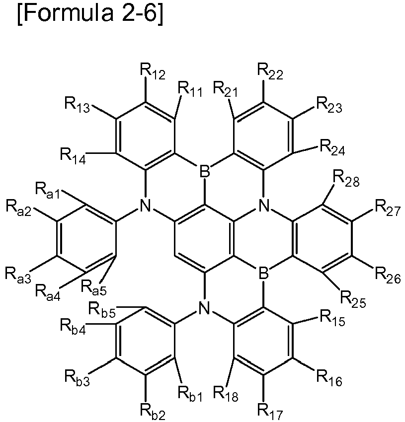
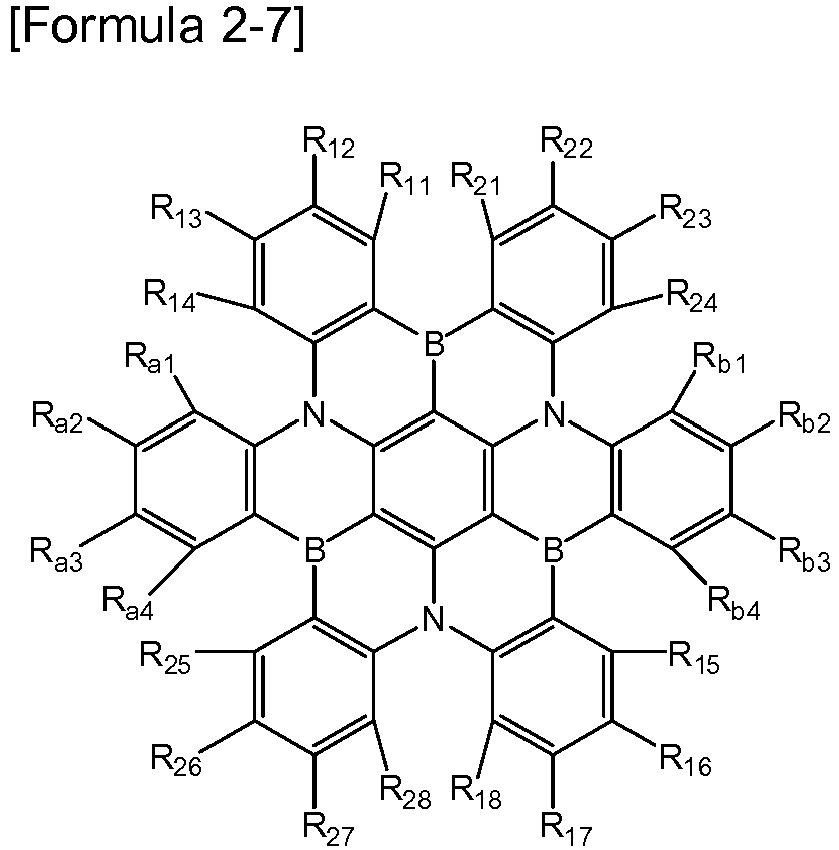
Ra1 to Ra10, Rb1 to Rb10, R11 to R18, R21 to R28, and R31 to R36 are each independently hydrogen; deuterium; a halogen; a substituted or unsubstituted tri(C1-20 alkyl)silyl; a substituted or unsubstituted tri(C6-20 aryl)silyl; a substituted or unsubstituted C1-20 alkyl; a substituted or unsubstituted C1-20 haloalkyl; a substituted or unsubstituted C1-20 alkoxy; a substituted or unsubstituted C1-20 haloalkoxy; a substituted or unsubstituted C6-20 aryl; a substituted or unsubstituted C6-20 aryloxy; or a substituted or unsubstituted C2-20 heteroaryl containing at least one heteroatom selected from the group consisting of N, O, and S, wherein adjacent substituents of Ra1 to Ra6 and Rb1 to Rb6 are optionally connected to each other to form a substituted or unsubstituted C6-20 aromatic ring,
with that proviso that at least one of Ra1 to Ra10, Rb1 to Rb10, R11 to R18, R21 to R28, and R31 to R36 in one formula is a substituted or unsubstituted tri(C1-20 alkyl)silyl group or a substituted or unsubstituted tri(C6-20 aryl)silyl group; or is substituted by a tri(C1-20 alkyl)silyl group or a tri(C6-20 aryl)silyl group. - For example, in Formulas 2-1 to 2-7, at least one of Ra1 to Ra10, Rb1 to Rb10, R11 to R18, R21 to R28, and R31 to R36 is -Si(CH3)3, or may be substituted by -Si(CH3)3.
- Further, in Formulas 2-1 to 2-7, Ra1 to Ra10, Rb1 to Rb10, R11 to R18, R21 to R28, and R31 to R36 may each independently be hydrogen, -Si(CH3)3, or -CH3.
- Specifically, for example, the compound containing a structural unit represented by
Formula 1 may be represented by one of the following Formulas 2-1A to 2-7A: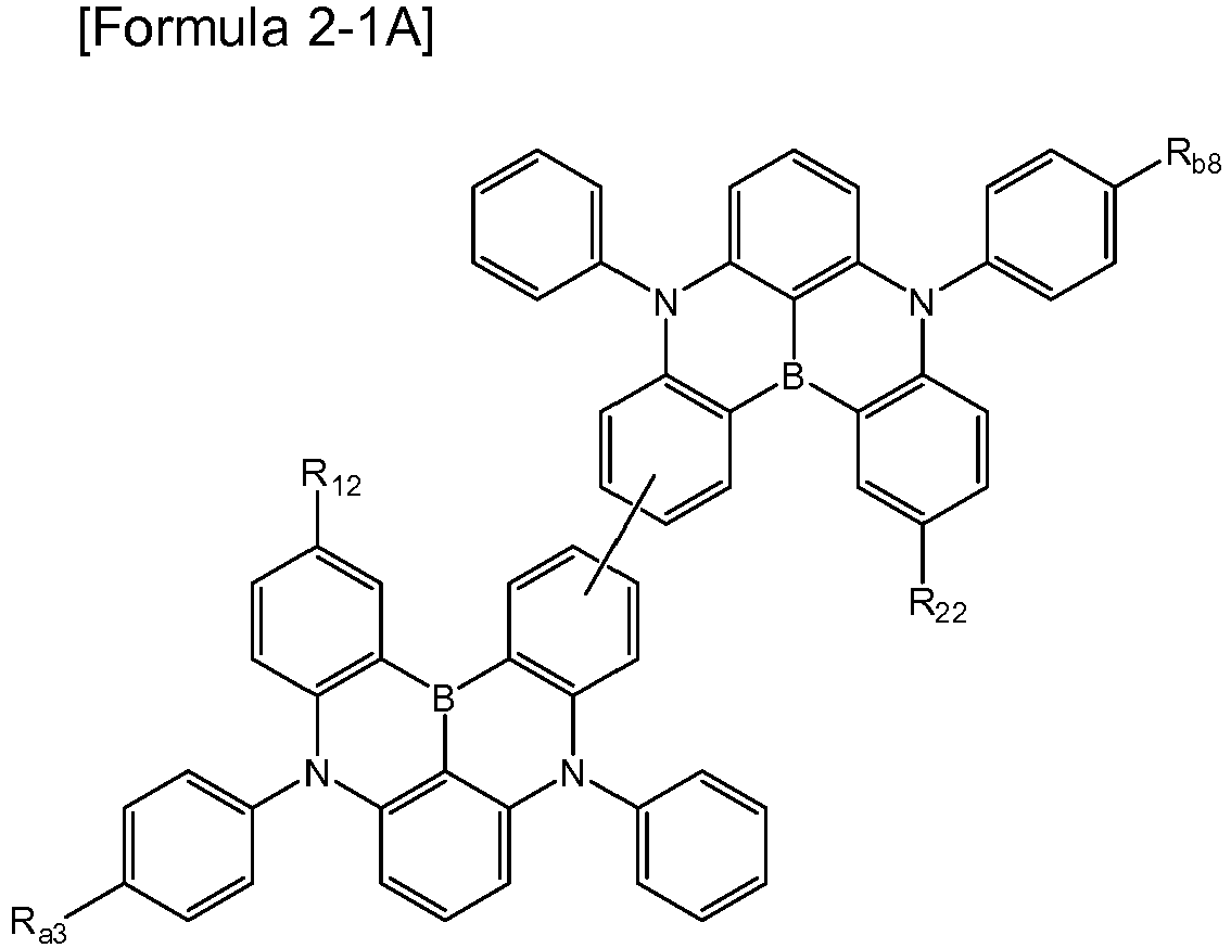


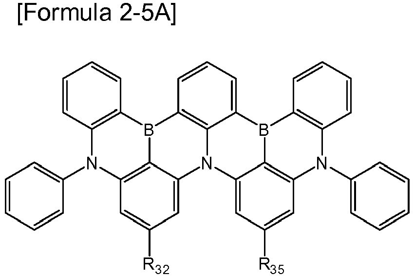


Ra1 to Ra3, Ra8, Rb1 to Rb3, Rb8, R12, R16, R22, R26, R32, and R35 are as defined in Formulas 2-1 to 2-7, respectively,
with the proviso that at least one of Ra1 to Ra3, Ra8, Rb1 to Rb3, Rb8, R12, R16, R22, R26, R32, and R35 in one formula is -Si(CH3)3, or is substituted by -Si(CH3)3. - More specifically, for example, the above compound may be any one selected from the group consisting of the following compounds:


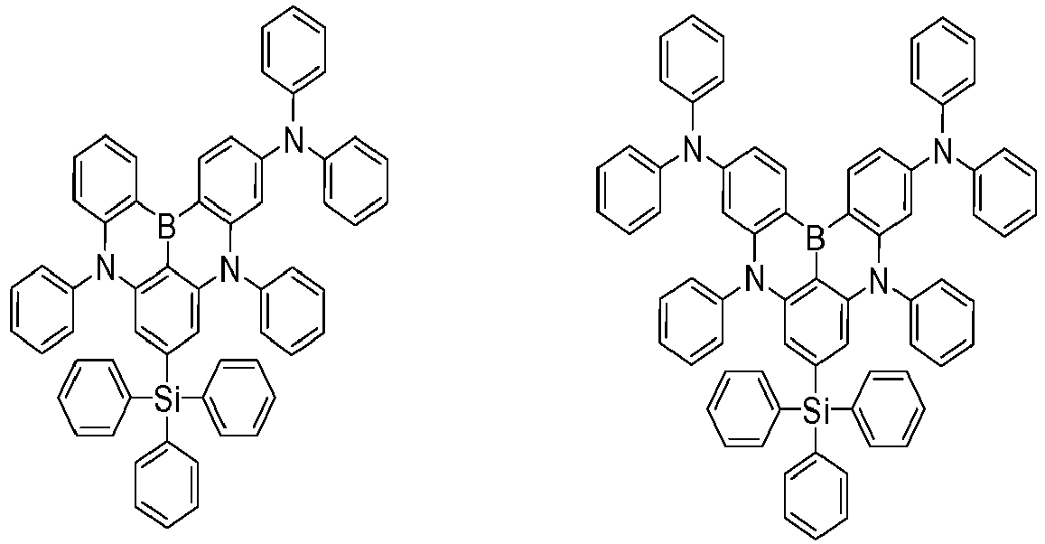


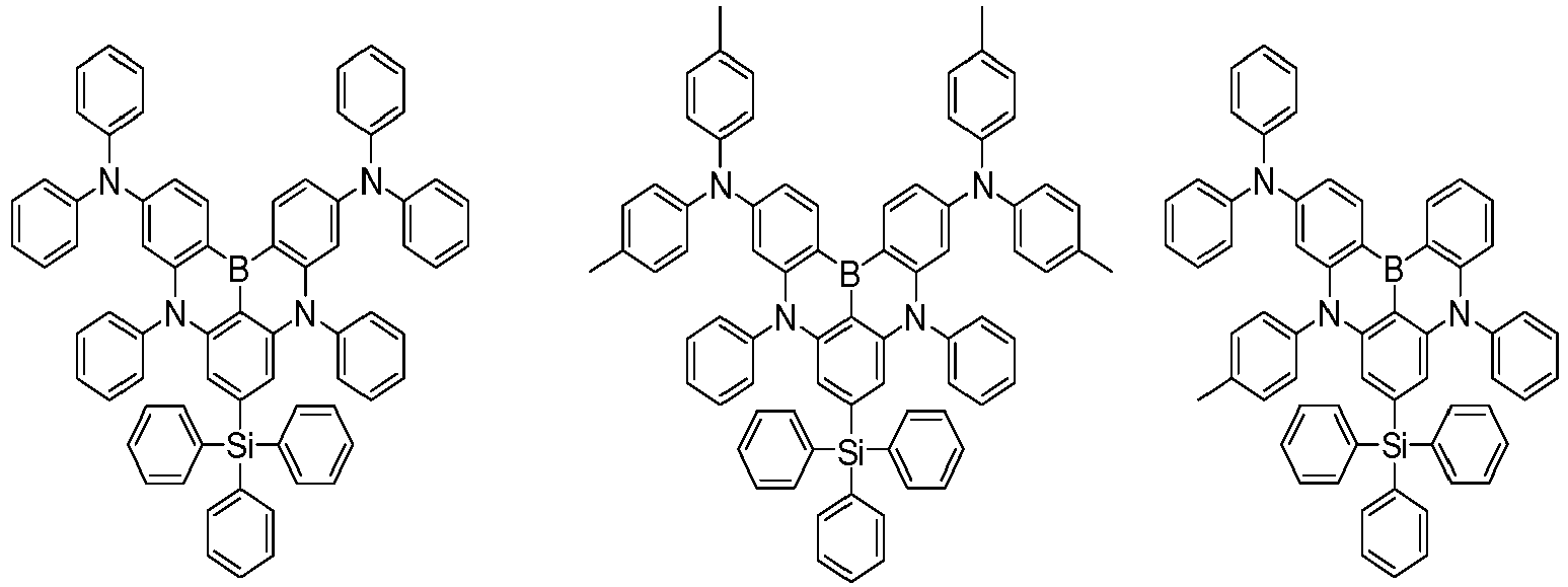


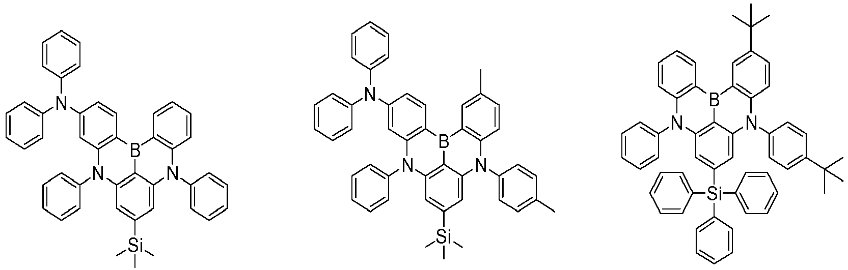


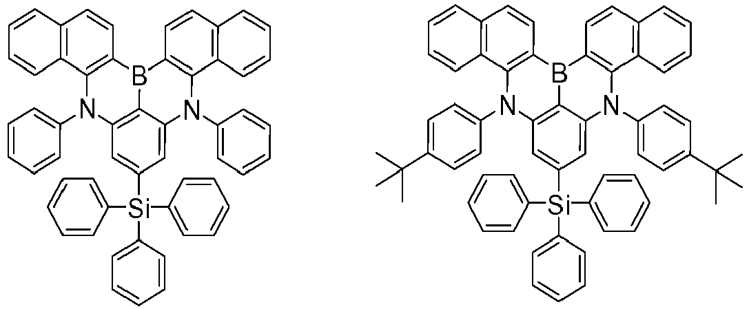


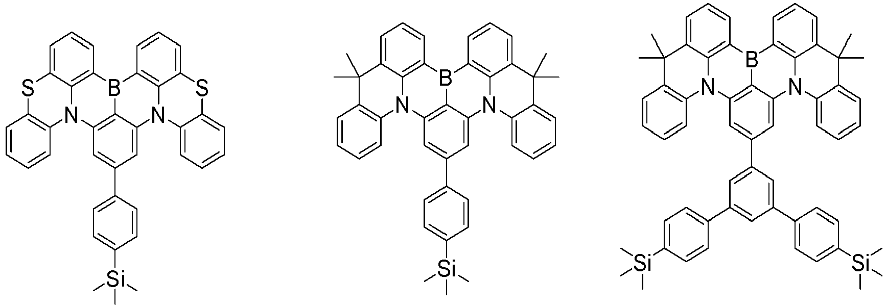
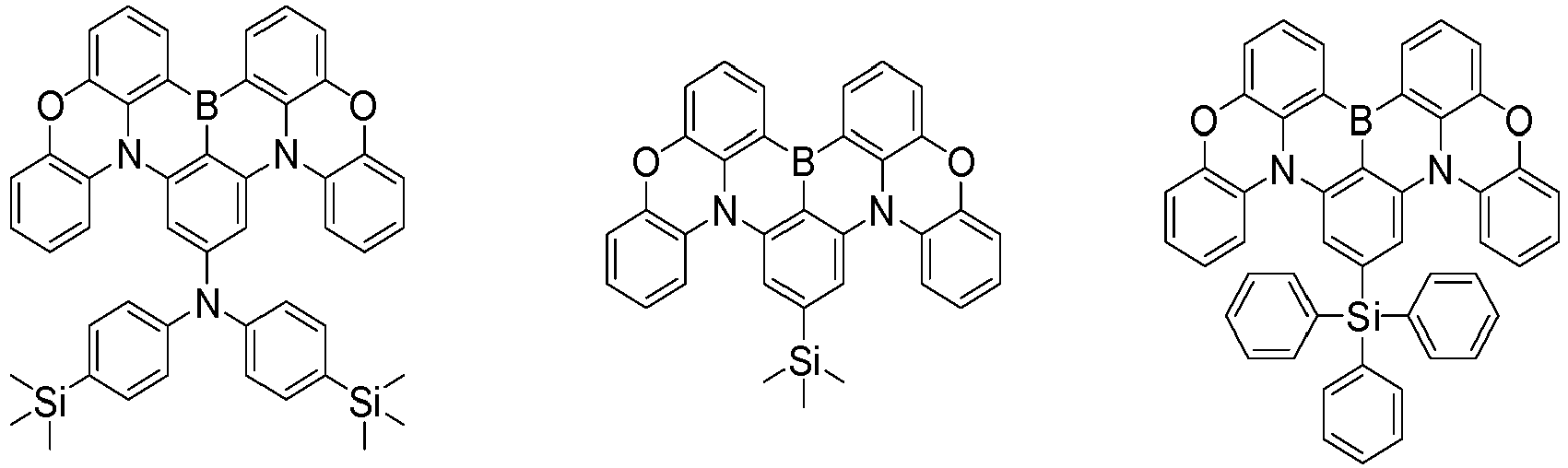


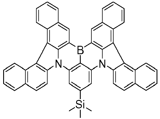


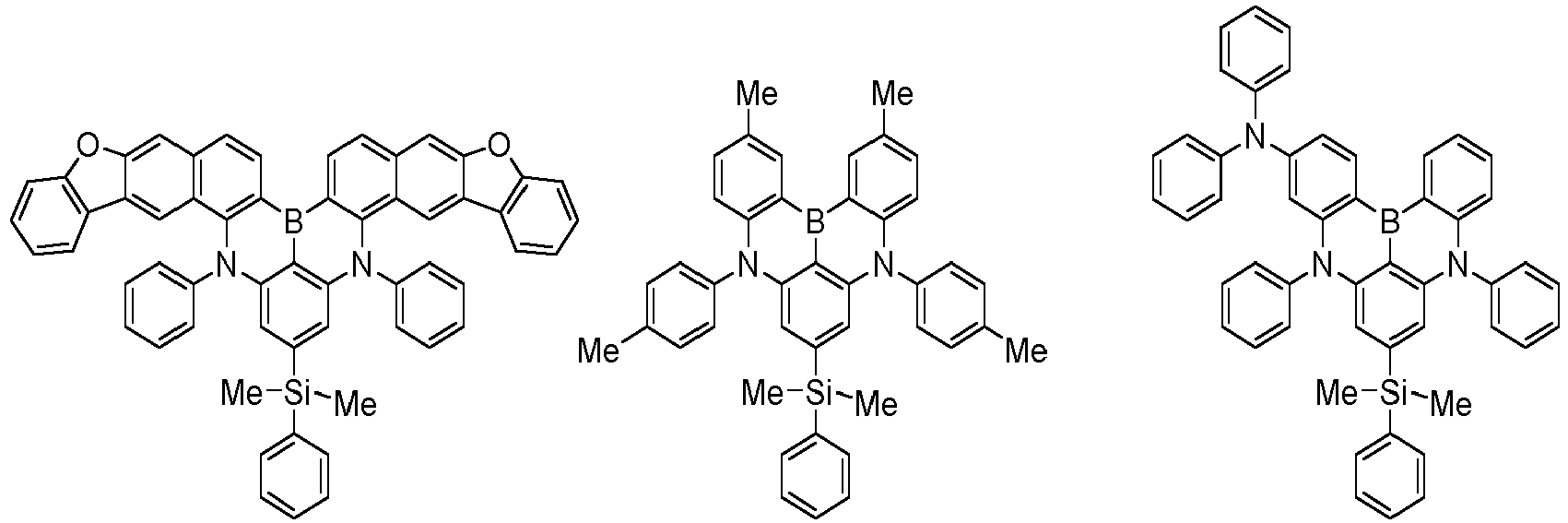


- The compound represented by
Formula 1 and the compound containing a structural unit represented byFormula 1 each have at least one substituted or unsubstituted silyl group, or have a substituent group substituted with at least one silyl group. Thereby, in an organic light emitting device employing the same, particularly a blue thermally activated delayed fluorescence (TADF) device and a blue fluorescent device, the quantum efficiency can be improved as compared with an organic light emitting device employing a compound having no silyl substituent. - Meanwhile, the compound represented by
Formula 1 can be prepared, for example, by the preparation method as shown in the followingReaction Scheme 1. The preparation method can be further specified in the preparation examples to be described later.
- In
Reaction Scheme 1, AI to A3 are as defined inFormula 1, R is as defined for Ra, Rb, and R1 to R3 inFormula 1, and Z means a halogen or hydrogen. - The compound represented by
Formula 1 can be prepared by appropriately substituting the starting material according to the structure of the compound to be prepared with reference toReaction Scheme 1. - Meanwhile, the present invention provides an organic light emitting device including the compound represented by
Formula 1. In one example, the present invention provides an organic light emitting device including: a first electrode; a second electrode provided at a side opposite to the first electrode; and at least one layer of organic material layers provided between the first electrode and the second electrode, wherein the at least one layer of the organic material layers includes a compound represented byFormula 1. - The organic material layer of the organic light emitting device of the present invention may have a single layer structure, or it may have a multilayered structure in which two or more organic material layers are stacked. For example, the organic light emitting device of the present invention may have a structure including a hole injection layer, a hole transport layer, a light emitting layer, an electron transport layer, an electron injection layer, and the like as the organic material layer. However, the structure of the organic light emitting device is not limited thereto, and it may include a smaller number of organic layers.
- The organic material layer of the organic light emitting device of the present invention may have a single layer structure, but it may have a multilayered structure in which two or more organic material layers are stacked. For example, the organic light emitting device of the present invention may have a structure further including a hole injection layer and a hole transport layer between the first electrode and the light emitting layer, and an electron transport layer and an electron injection layer between the light emitting layer and the second electrode, in addition to the light emitting layer as an organic material layer. However, the structure of the organic light emitting device is not limited thereto, and it may include a smaller or greater number of organic layers.
- Further, the organic light emitting device according to the present invention may be a normal type of organic light emitting device in which an anode, at least one organic material layer, and a cathode are sequentially stacked on a substrate. Further, the organic light emitting device according to the present invention may be an inverted type of organic light emitting device in which a cathode, at least one organic material layer, and an anode are sequentially stacked on a substrate. For example, the structure of an organic light emitting device according to an embodiment of the present invention is illustrated in
FIGS. 1 and 2 . -
FIG. 1 shows an example of an organic light emitting device including asubstrate 1, ananode 2, alight emitting layer 3, and acathode 4. In such a structure, the compound represented byFormula 1 may be included in the light emitting layer. -
FIG. 2 shows an example of an organic light emitting device including asubstrate 1, ananode 2, a hole injection layer 5, ahole transport layer 6, alight emitting layer 7, anelectron transport layer 8, and acathode 4. In such a structure, the compound represented byFormula 1 may be included in at least one layer of the hole injection layer, the hole transport layer, the light emitting layer, and the electron transport layer, and it is preferably included in the light emitting layer. - The organic light emitting device according to the present invention may be manufactured by materials and methods known in the art, except that at least one layer of the organic material layers includes the compound represented by
Formula 1. In addition, when the organic light emitting device includes a plurality of organic material layers, the organic material layers may be formed of the same material or different materials. - For example, the organic light emitting device according to the present invention can be manufactured by sequentially stacking a first electrode, an organic material layer, and a second electrode on a substrate. In this case, the organic light emitting device may be manufactured by depositing a metal, metal oxides having conductivity, or an alloy thereof on the substrate by using a PVD (physical vapor deposition) method such as a sputtering method or an e-beam evaporation method to form the anode, forming an organic material layer including the hole injection layer, the hole transport layer, the light emitting layer, and the electron transport layer thereon, and then depositing a material that can be used as the cathode thereon. In addition to such a method, the organic light emitting device may be manufactured by sequentially depositing a cathode material, an organic material layer, and an anode material on a substrate.
- In particular, the compound represented by
Formula 1 may be included in the light emitting layer, and the light emitting layer is not manufactured by a solution coating method including an organic solvent, but is manufactured by a vacuum deposition method, thereby enabling improvement of the efficiency and the low driving voltage, and/or improvement of the lifetime characteristic. - In addition to such a method, the organic light emitting device may be manufactured by sequentially depositing a cathode material, an organic material layer, and an anode material on a substrate (International Publication
WO 2003/012890 ). However, the manufacturing method is not limited thereto. - For example, the first electrode is an anode and the second electrode is a cathode, or the first electrode is a cathode and the second electrode is an anode.
- As the anode material, generally, a material having a large work function is preferably used so that holes can be smoothly injected into the organic material layer. Specific examples of the anode material include metals such as vanadium, chrome, copper, zinc, and gold, or an alloy thereof; metal oxides such as zinc oxides, indium oxides, indium tin oxides (ITO), and indium zinc oxides (IZO); a combination of metals and oxides, such as ZnO:Al or SNO2:Sb; conductive polymers such as poly(3-methylthiophene), poly[3,4-(ethylene-1,2-dioxy)thiophene] (PEDOT), polypyrrole, polyaniline, and the like, but are not limited thereto.
- As the cathode material, generally, a material having a small work function is preferably used so that electrons can be easily injected into the organic material layer. Specific examples of the cathode material include metals such as magnesium, calcium, sodium, potassium, titanium, indium, yttrium, lithium, gadolinium, aluminum, silver, tin, and lead, or an alloy thereof; and a multilayered structure material such as LiF/Al, LiO2/Al, and the like, but are not limited thereto.
- The hole injection layer is a layer for injecting holes from the electrode, and the hole injection material is preferably a compound which has an ability of transporting the holes, a hole injecting effect in the anode, and an excellent hole injecting effect to the light emitting layer or the light emitting material, that prevents movement of an exciton generated in the light emitting layer to the electron injection layer or the electron injection material, and has an excellent thin film forming ability. It is preferable that a HOMO (highest occupied molecular orbital) of the hole injection material is between the work function of the anode material and a HOMO of a peripheral organic material layer. Specific examples of the hole injection material include a compound represented by
Formula 1 according to the present invention, or a metal porphyrin, an oligothiophene, an arylamine-based organic material, a hexanitrilehexaazatriphenylene-based organic material, a quinacridone-based organic material, a perylene-based organic material, anthraquinone, polyaniline, a polythiophene-based conductive polymer, and the like, but are not limited thereto. - The hole transport layer is a layer that receives holes from a hole injection layer and transports the holes to the light emitting layer. The hole transport material is suitably a material having large mobility to the holes, which may receive holes from the anode or the hole injection layer and transfer the holes to the light emitting layer. Specific examples thereof include an arylamine-based organic material, a conductive polymer, a block copolymer in which a conjugate portion and a non-conjugate portion are present together, and the like, but are not limited thereto.
- The light emitting material is a material capable of emitting light in the visible light region by combining holes and electrons respectively transported from the hole transport layer and the electron transport layer, and having good quantum efficiency for fluorescence or phosphorescence. Specific examples include an 8-hydroxyquinoline aluminum complex (Alq3); carbazole-based compounds; dimerized styryl compounds; BAIq; 10-hydroxybenzoquinoline-metal compounds; benzoxazole, benzothiazole, and benzimidazole-based compounds; poly(p-phenylenevinylene)(PPV)-based polymers; spiro compounds; and polyfluorene, rubrene, and the like, but are not limited thereto.
- The light emitting layer may include a host material and a dopant material as described above. The compound represented by
Formula 1 may be a dopant material, and the content of the dopant material may be 0.5 to 20 % by weight with respect to the total content of the light emitting layer. - The host material may further include a fused aromatic ring derivative, a heterocycle-containing compound, or the like. Specifically, the host material is preferably a compound represented by the following
Formula 3.
- In
Formula 3,
Ar is a C6-20 aryl or a C2-60 heteroaryl containing at least one heteroatom selected from the group consisting of N, O, and S, and
n may be an integer of 1 to 10. - The compound represented by
Formula 3 may be a compound represented by the followingFormula 4.
- In
Formula 4,
Ar1 to Ar4 are each independently a C6-20 aryl or a C2-60 heteroaryl containing at least one heteroatom selected from the group consisting of N, O, and S,
X may be a compound selected from the group consisting of:
Ar5 is phenyl, biphenylyl, terphenylyl, naphthyl, phenanthryl, fluorenyl, chrysenyl, triphenylenyl, pyrenylyl, carbazolyl, or phenyl-substituted carbazolyl. - The electron transport layer is a layer receiving the electrons from the electron injection layer and transporting the electrons to the light emitting layer, the electron transport material is a material that can receive the electrons well from the cathode and transport the electrons to the light emitting layer, and a material having large mobility to the electrons is suitable. Specific examples thereof include an 8-hydroxyquinoline Al complex; a complex including Alq3; an organic radical compound; a hydroxyflavone-metal complex; and the like, but are not limited thereto. The electron transport layer may be used together with a predetermined desired cathode material as used according to the prior art. Particularly, an example of an appropriate cathode material is a general material having a low work function and followed by an aluminum layer or a silver layer. Specific examples thereof include cesium, barium, calcium, ytterbium, and samarium, and each case is followed by the aluminum layer or the silver layer.
- The electron injection layer is a layer injecting the electrons from the electrode, and a compound which has an ability of transporting the electrons, an electron injecting effect from the cathode, and an excellent electron injecting effect to the light emitting layer or the light emitting material, that prevents movement of an exciton generated in the light emitting layer to the hole injection layer, and has an excellent thin film forming ability is preferable. Specific examples thereof include fluorenone, anthraquinodimethane, diphenoquinone, thiopyran dioxide, oxazole, oxadiazole, triazole, imidazole, perylene tetracarboxylic acid, fluorenylidene methane, anthrone, and the like, and derivatives thereof, a metal complex compound, a nitrogen-containing 5-membered cycle derivative, and the like, but are not limited thereto.
- Examples of the metal complex compound include 8-hydroxyquinolinato lithium, bis(8-hydroxyquinolinato)zinc, bis(8-hydroxyquinolinato)copper, bis(8-hydroxyquinolinato)manganese, tris(8-hydroxyquinolinato)aluminum, tris(2-methyl-8-hydroxyquinolinato)aluminum, tris(8-hydroxyquinolinato)gallium, bis(10-hydroxybenzo[h]quinolinato)beryllium, bis(10-hydroxybenzo[h]quinolinato)zinc, bis(2-methyl-8-quinolinato)chlorogallium, bis(2-methyl-8-quinolinato)(o-cresolato)gallium, bis(2-methyl-8-quinolinato)(1-naphtholato)aluminum, bis(2-methyl-8-quinolinato)(2-naphtholato)gallium, and the like, but are not limited thereto.
- The organic light emitting device according to the present invention may be a front emission type, a back emission type, or a double side emission type according to the material used.
- In addition, the compound represented by
Formula 1 may be included in an organic solar cell or an organic transistor in addition to an organic light emitting device. - The preparation of the compound represented by
Formula 1 and the organic light emitting device including the same will be described in detail in the following examples. However, these examples are presented for illustrative purposes only, and the scope of the present invention is not limited thereto. -

- A flask containing 1-bromo-2,3-dichlorobenzene (22.6 g), bis(4-(tert-butyl)phenyl)amine (58.0 g), Pd(PtBu3)2 (0.5 g), NaOtBu (25.0 g), and xylene (260 ml) was heated to 130 °C and stirred for 4 hours. The reaction solution was cooled to room temperature, and water and ethyl acetate are added to separate liquid layers. The solvent was then distilled off under reduced pressure. It was purified by silica gel column chromatography (developer: hexane/ethyl acetate = 50 %/50 % (v/v)) to obtain Intermediate 1-A (20.4 g). The mass spectrum of the solid was measured, and as a result, a peak was confirmed at M/Z=671.
-

- A 1.7 M tert-butyllithium pentane solution (9.2 ml) was added to a flask containing Intermediate 1-A (10.0 g) and tert-butylbenzene (160 ml) at 0 °C under an argon atmosphere. After completion of the dropwise addition, the temperature was raised to 70 °C, and the mixture was stirred for 4 hours to distill off pentane. After cooling to -40 °C, boron tribromide (1.6 ml) was added thereto, and the mixture was warmed to room temperature and stirred for 4 hours. Thereafter, the mixture was cooled again to 0 °C, and N,N-diisopropylethylamine (6.6 ml) was added thereto and stirred at room temperature, followed by stirring at 80 °C for 4 hours. The reaction solution was cooled to room temperature, and water and ethyl acetate were added thereto to separate liquid layers. The solvent was then distilled off under reduced pressure. Acetonitrile was added thereto to obtain Intermediate 1-B (2.8 g). The mass spectrum of the obtained solid was measured, and as a result, a peak was confirmed at M/Z=645.
-

- Intermediate 1-B (4.0 g) was dissolved in 300 ml of chloroform, and N-bromosuccinimide (1.2 g) was added thereto over 30 minutes and then stirred at room temperature for 4 hours. Distilled water was added to the reaction solution to complete the reaction, and the organic layer was extracted. The reaction solution was concentrated, and Compound 1-C (2.0 g) was obtained using column chromatography (developer: hexane/ethyl acetate=50 %/50 % (v/v)). A peak was confirmed at M/Z=724.
-

- Intermediate 1-C (2.0 g) was dissolved in 200 ml of anhydrous tetrahydrofuran under a nitrogen atmosphere, and the ambient temperature of the reactor was maintained at -78 °C. Then, 1.1 ml of 2.5 M-butyllithium was slowly added dropwise. After completion of the dropwise addition, stirring was performed for 1 hour, 0.6 ml of chlorotrimethylsilane was dissolved in 20 ml of purified tetrahydrofuran, and then slowly added dropwise. The reaction solution was stirred for about 1 hour while being maintained at -78 °C, and then diluted hydrochloric acid was added to the reaction solution to complete the reaction. Liquid layers were separated and extracted with methylene chloride. The resultant organic layer was dried with magnesium sulfate, filtered, and then distilled under reduced pressure. Column chromatography (developer: hexane/ethyl acetate = 50 %/50 % (v/v)) was used to prepare Compound 1 (0.4 g). The mass spectrum of the obtained solid was measured, and as a result, a peak was confirmed at M/Z=717.
- The
Compound 1 was measured using a spectrophotometer U-3310 (manufactured by Hitachi High-Tech Science Corporation), and the absorption peak wavelength was observed at 437 nm. Further,Compound 1 was measured using a fluorescence spectrum measuring device, fluorescence spectrophotometer F-7000 (manufactured by Hitachi High-Tech Science Corporation), and the phosphor light emission peak wavelength was observed at 452 nm.FIG. 3 is a graph in which the absorption peak wavelength of thecompound 1 is measured by fluorescence spectrophotometry. - In addition, the half-value width was measured using fluorescence spectrophotometer F-7000 (manufactured by Hitachi High-Tech Science Corporation), and the measurement method is as follows. Specifically,
Compound 1 was dissolved in a solvent (toluene) (sample 5 [µmol/mL]) and used as a sample for fluorescence measurement. A sample for fluorescence measurement placed in a quartz cell was irradiated with excitation light at room temperature, and the fluorescence intensity was measured while changing the wavelength. In the light emission spectrum, the vertical axis represents fluorescence intensity, and the horizontal axis represents wavelength. The half-value width was measured from this light emission spectrum, and as a result, the half-value width ofCompound 1 was 30 nm.FIG. 4 is a graph in which the half-value width ofCompound 1 is measured by fluorescence spectrophotometry. -

- Compound 2 (0.2 g) was prepared in the same manner as in the step 1-d for synthesizing
Compound 1, except that 0.6 ml of chlorotrimethylsilane was changed to 0.8 ml of chloro(dimethyl)phenylsilane. The mass spectrum of the obtained solid was measured, and as a result, a peak was confirmed at M/Z=779. -

- A flask containing 1-bromo-2,3-dichlorobenzene (22.6 g), bis(4-(tert-butyl)phenyl)amine (28.2 g), Pd(PtBu3)2 (0.2 g), NaOtBu (12.6 g), and toluene (130 ml) was heated to 110 °C and stirred for 4 hours. The reaction solution was cooled to room temperature, and water and ethyl acetate were added to separate liquid layers. The solvent was then distilled off under reduced pressure. It was purified by silica gel column chromatography (developer: hexane/ethyl acetate=50 %/50 % (v/v)) to obtain Intermediate 3-A (20.8 g). The mass spectrum of the obtained solid was measured, and as a result, a peak was confirmed at M/Z=426.
-

- A flask containing Intermediate 3-A (41.1 g), di-p-tolylamine (20.6 g), Pd(PtBu3)2 (0.2 g), NaOtBu (12.6 g), and toluene (130 ml) was heated to 110 °C and stirred for 4 hours. The reaction solution was cooled to room temperature, and water and ethyl acetate were added to separate liquid layers. The solvent was then distilled off under reduced pressure. It was purified by silica gel column chromatography (developer: hexane/ethyl acetate=50 %/50 % (v/v)) to obtain Intermediate 3-B (19.2 g). The mass spectrum measurement of the obtained solid was measured, and as a result, a peak was confirmed at M/Z=587.
-

- Intermediate 3-C (3.0 g) was obtained in the same manner as in the step 1-b for synthesizing Intermediate 1-B, except that Intermediate 1-A was changed to Intermediate 3-B (8.7 g). The mass spectrum of the obtained solid was measured, and as a result, a peak was confirmed at M/Z=561.
-

- Intermediate 3-D (1.6 g) was obtained in the same manner as in the step 1-c for synthesizing Intermediate 1-C, except that Intermediate 1-B was changed to Intermediate 3-C (3.5 g). The mass spectrum of the obtained solid was measured, and as a result, a peak was confirmed at M/Z=639.
-

- Compound 3 (0.3 g) was obtained in the same manner as in the step 1-d for synthesizing
Compound 1, except that Intermediate 1-C was changed to Intermediate 3-D (1.8 g). The mass spectrum of the obtained solid was measured, and as a result, a peak was confirmed at M/Z=633. -

- Diisopropylamine (15.5 ml) was added to 200 ml of anhydrous tetrahydrofuran under a nitrogen atmosphere, and then 42.0 ml of 2.5M-butyllithium was slowly added dropwise at -78 °C. The reaction solution was stirred for about 2 hours while being maintained at -78 °C. 49.4 g of (3,5-dibromophenyl)triphenylsilane was dissolved in 100 ml of tetrahydrofuran and slowly added dropwise. After stirring at -78 °C for 2 hours, an excess amount of carbon dioxide gas was added and the temperature was gradually raised to room temperature. The diluted hydrochloric acid was added to the reaction solution to complete the reaction, and then liquid layers were separated and extracted with methylene chloride. The resultant organic layer was dried with magnesium sulfate, filtered, and then distilled under reduced pressure. Column chromatography (developer: hexane/ethyl acetate = 60 %/40 % (v/v)) was used to prepare 34.2 g of 2,6-dibromo-4-(triphenylsilyl)benzoic acid.
- Subsequently, 34.2 g of 2,6-dibromo-4-(triphenylsilyl)benzoic acid was dissolved in 160 ml of sulfuric acid and heated at 60 °C for 2 hours. After cooling to room temperature, sodium azide (NaN3) (8.2 g) was added, and stirred at 0 °C for 48 hours. After completion of the reaction, liquid layers were separated and extracted using ammonia water and ethyl acetate. The resultant organic layer was dried with magnesium sulfate, filtered, and then distilled under reduced pressure. Column chromatography (developer: ethyl acetate) was used to prepare 22.6 g of 2,6-dibromo-4-(triphenylsilyl)aniline.
- Subsequently, 2,6-dibromo-4- (triphenylsilyl)aniline (22.6 g) was suspended in a sulfuric acid aqueous solution, and 6.0 g of sodium nitrite was added at 0 °C to perform diazotization. Thereafter, an aqueous solution of urea was added. This solution was added to a hydrochloric acid aqueous solution of CuCl2 (13.1 g) over a plurality of additions, and stirred at room temperature for 2 hours and at 60 °C for 4 hours. After completion of the reaction, liquid layers were separated and extracted using ammonia water and ethyl acetate. The resultant organic layer was dried with magnesium sulfate, filtered, and distilled under reduced pressure. The precipitated solid was washed with water and ethanol and dried to obtain Intermediate 4-A (10.6 g). The mass spectrum of the obtained solid was measured, and as a result, a peak was confirmed at M/Z=529.
-
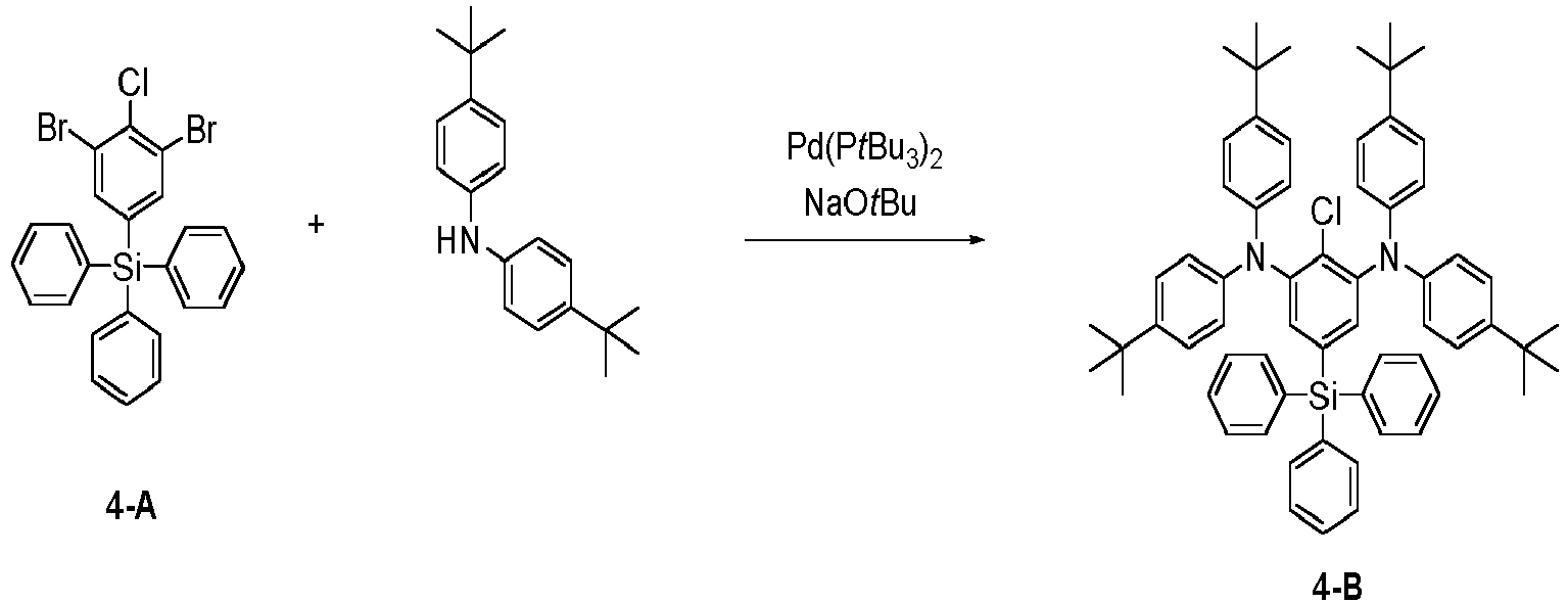
- Intermediate 4-B (36.0 g) was obtained in the same manner as in the step 1-a for synthesizing Intermediate 1-A, except that 1-bromo-2,3-dichlorobenzene (22.6 g) was changed to Intermediate 4-A (52.9 g). The mass spectrum of the obtained solid was measured, and as a result, a peak was confirmed at M/Z=930.
-

- Compound 4 (1.2 g) was obtained in the same manner as in the step 1-b for synthesizing Intermediate 1-B, except that Intermediate 1-A was changed to Intermediate 4-B (13.8 g). The mass spectrum of the obtained solid was measured, and as a result, a peak was confirmed at M/Z=903.
-

- Compound 5-A (29.0 g) was obtained in the same manner as in the step 4-b for synthesizing Intermediate 4-B, except that bis(4-(tert-butyl)phenyl)amine (58.0 g) was changed to di-p-tolylamine (40.7 g). The mass spectrum of the obtained solid was measured, and as a result, a peak was confirmed at M/Z=761.
-

- Compound 5 (1.8 g) was obtained in the same manner as in the step 4-b for synthesizing Compound 4-B, except that Intermediate 4-B (13.8 g) was changed to Intermediate 5-A (11.3 g). The mass spectrum of the obtained solid was measured, and as a result, a peak was confirmed at M/Z=735.
-

- A flask containing Intermediate 4-A (26.4 g), N-phenylnaphthalen-1-amine (24.0 g), Pd(PtBu3)2 (0.4 g), NaOtBu (13.0 g), and xylene (260 ml) was heated to 130 °C and stirred for 4 hours. The reaction solution was cooled to room temperature, and water and ethyl acetate were added to separate liquid layers. The solvent was then distilled off under reduced pressure. It was purified by silica gel column chromatography (developer: hexane/ethyl acetate=50 %/50 %(v/v)) to obtain Intermediate 6-A (12.8 g). The mass spectrum of the obtained solid was measured, and as a result, a peak was confirmed at M/Z=805.
-
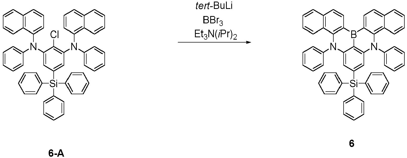
- Compound 6 (2.0 g) was obtained in the same manner as in the step 4-b for synthesizing
Compound 4, except that Intermediate 4-B (13.8 g) was changed to Intermediate 6-A (12.0 g). The mass spectrum of the obtained solid was measured, and as a result, a peak was confirmed at M/Z=779. -

- Intermediate 7-A (10.6 g) was obtained in the same manner as in the step 6-a for synthesizing Compound 6-A, except that N-phenylnaphthalen-1-amine (24.0 g) was changed to N-(m-tolyl)naphthalen-1-amine (25.5 g). The mass spectrum of the obtained solid was measured, and as a result, a peak was confirmed at M/Z=834.
-

- Compound 7 (2.2 g) was obtained in the same manner as in the step 4-b for synthesizing
Compound 4, except that Intermediate 4-B (13.8 g) was changed to Intermediate 7-A (12.4 g). The mass spectrum of the obtained solid was measured, and as a result, a peak was confirmed at M/Z=807. -

- Diisopropylamine (15.5 ml) was added to 200 ml of anhydrous tetrahydrofuran under a nitrogen atmosphere, and then 42.0 ml of 2.5M-butyllithium was slowly added dropwise at -78 °C. The reaction solution was stirred for about 2 hours while being maintained at -78 °C, and 37.0 g of (3,5-dibromophenyl)dimethyl(phenyl)silane was dissolved in 100 ml of tetrahydrofuran, and slowly added dropwise. After stirring at -78 °C for 2 hours, an excess amount of carbon dioxide gas was added, and the temperature was gradually raised to room temperature. The diluted hydrochloric acid was added to the reaction solution to complete the reaction, and then liquid layers were separated and extracted using methylene chloride. The resultant organic layer was dried with magnesium sulfate, filtered, and distilled under reduced pressure. Column chromatography (developer: hexane/ethyl acetate=60 %/40 % (v/v)) was used to prepare 28.2 g of 2,6-dibromo-4-(dimethyl(phenyl)silyl)benzoic acid.
- Subsequently, 26.3 g of 2,6-dibromo-4-(dimethyl(phenyl)silyl)benzoic acid was dissolved in 160 ml of sulfuric acid and heated at 60 °C for 2 hours. After cooling to room temperature, sodium azide (NaN3) (8.2 g) was added, and stirred at 0 °C for 48 hours. After completion of the reaction, liquid layers were separated and extracted using ammonia water and ethyl acetate. The resultant organic layer was dried with magnesium sulfate, filtered, and then distilled under reduced pressure. Column chromatography (developer: ethyl acetate) was used to prepare 16.6 g of 2,6-dibromo-4-(dimethyl(phenyl)silyl)aniline.
- Subsequently, 2,6-dibromo-4- (dimethyl(phenyl)silyl)aniline (17.1 g) was suspended in a sulfuric acid aqueous solution, and 6.0 g of sodium nitrite was added at 0 °C to perform diazotization. Thereafter, an aqueous solution of urea was added. This solution was added to a hydrochloric acid aqueous solution of CuCl2 (13.1 g) over a plurality of additions, and stirred at room temperature for 2 hours and at 60 °C for 4 hours. After completion of the reaction, liquid layers were separated and extracted using ammonia water and ethyl acetate. The resultant organic layer was dried with magnesium sulfate, filtered, and distilled under reduced pressure. The precipitated solid was washed with water and ethanol and dried to obtain Intermediate 8-A (6.8 g). The mass spectrum of the obtained solid was measured, and as a result, a peak was confirmed at M/Z=405.
-

- A flask containing Intermediate 8-A (10.1 g), bis(4-(tert-butyl)phenyl)amine (14.5 g), Pd(PtBu3)2 (0.2 g), NaOtBu (6.2 g), and xylene (70 ml) was heated to 130 °C and stirred for 4 hours. The reaction solution was cooled to room temperature, and water and ethyl acetate were added to separate liquid layers. The solvent was then distilled off under reduced pressure. Silica gel column chromatography (developer: hexane/ethyl acetate=50 %/50 % (v/v)) was used to prepare Intermediate 8-B (5.0 g). The mass spectrum of the obtained solid was measured, and as a result, a peak was confirmed at M/Z=792.
-

- Compound 8 (1.7 g) was obtained in the same manner as in the step 4-b for synthesizing
Compound 4, except that Intermediate 4-B (13.8 g) was changed to Intermediate 8-B (11.7 g). The mass spectrum of the obtained solid was measured, and as a result, a peak was confirmed at M/Z=779. -
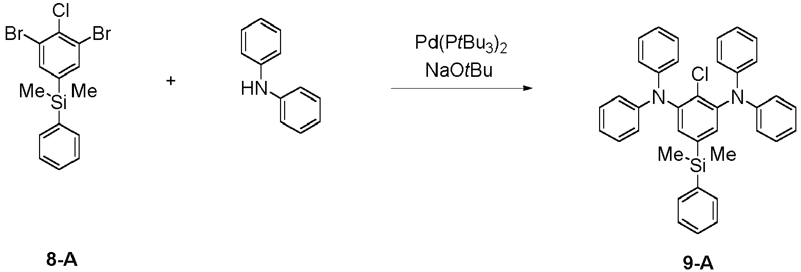
- Intermediate 9-A (4.2 g) was obtained in the same manner as in the step 8-b for synthesizing Intermediate 8-B, except that bis(4-(tert-butyl)phenyl)amine (14.5 g) was changed to diphenyl amine (8.7 g). The mass spectrum of the obtained solid was measured, and as a result, a peak was confirmed at M/Z=581.
-

- Compound 9 (1.0 g) was obtained in the same manner as in the step 4-b for synthesizing
Compound 4, except that Intermediate 4-B (13.8 g) was changed to Intermediate 9-A (8.6 g). The mass spectrum of the obtained solid was measured, and as a result, a peak was confirmed at M/Z=555. -

- Intermediate 10-A (4.6 g) was obtained in the same manner as in the step 8-b for synthesizing Intermediate 8-B, except that diphenylamine (8.7 g) was changed to N-phenylnaphthalen-1-amine (11.3 g). The mass spectrum of the obtained solid was measured, and as a result, a peak was confirmed at M/Z=681.
-

- Compound 10 (1.2 g) was obtained in the same manner as in the step 4-b for synthesizing
Compound 8, except that Intermediate 4-B (13.8 g) was changed to Intermediate 10-A (10.1 g). The mass spectrum of the obtained solid was measured, and as a result, a peak was confirmed at M/Z=655. -

- A flask containing 1,3-dibromo-2-chloro-5-methoxybenzene (7.5 g), diphenylamine (8.9 g), Pd(PtBu3)2 (0.2 g), NaOtBu (6.2 g), and xylene (60 ml) was heated to 130 °C and stirred for 4 hours. The reaction solution was cooled to room temperature, and water and ethyl acetate were added to separate liquid layers. The solvent was then distilled off under reduced pressure. It was purified by silica gel column chromatography (developer: hexane/ethyl acetate=50 %/50 % (v/v)) to prepare Intermediate 11-A (3.2 g). The mass spectrum of the obtained solid was measured, and as a result, a peak was confirmed at M/Z=477.
-

- Intermediate 11-B (2.0 g) was obtained in the same manner as in the step 4-b for synthesizing
Compound 4, except that Intermediate 4-B (13.8 g) was changed to Intermediate 11-A (7.1 g). The mass spectrum of the obtained solid was measured, and as a result, a peak was confirmed at M/Z=450. -

- To a flask containing Intermediate 11-B (4.4 g) and chloroform (100 ml) was added boron tribromide (1.0 ml) at room temperature under a nitrogen atmosphere, and the mixture was stirred at room temperature for 48 hours. Thereafter, the reaction solution was distilled off, a sodium hydrogen carbonate aqueous solution (200 ml) was added, and liquid layers were separated with chloroform. The solvent was distilled off under reduced pressure to obtain Intermediate 11-C (2.8 g). The mass spectrum of the obtained solid was measured, and as a result, a peak was confirmed at M/Z=436.
-

- Intermediate 11-C (2.8 g), nonafluorobutane-1-sulfonyl fluoride (2.2 g), and potassium carbonate (1.5 g) were dissolved in acetonitrile (40 ml), heated to 50 °C, and stirred for 4 hours. After cooling to room temperature, distilled water was added to remove potassium carbonate. Thereby, Intermediate 11-D (1.4 g) was obtained.
-

- Intermediate 11-D (2.4 g), (4-(trimethylsilyl) phenyl)boronic acid (0.8 g) and potassium carbonate (1.4 g) were dissolved in 20 ml of tetrahydrofuran and 10 ml of distilled water, and tetrakis(triphenylphosphine)palladium (0.2 g) was added thereto and then refluxed for 12 hours. After cooling to room temperature, the aqueous layer was removed, magnesium sulfate was added to the organic layer, and then filtered. After concentration, acetonitrile was added to obtain Compound 11 (0.6 g). The mass spectrum of the obtained solid was measured, and as a result, a peak was confirmed at M/Z=569.
-

- Intermediate 11-D (2.4 g) was dissolved in 24 ml of anhydrous tetrahydrofuran under a nitrogen atmosphere, and the ambient temperature of the reactor was maintained at -78 °C. Then, 1.4 ml of 2.5 M-butyllithium was slowly added dropwise. After completion of the dropwise addition, stirring was performed for 1 hour, and 0.7 ml of chlorotrimethylsilane was dissolved in 10 ml of purified tetrahydrofuran and then slowly added dropwise. The reaction solution was stirred for about 1 hour while being maintained at -78 °C, and then diluted hydrochloric acid was added to the reaction solution to complete the reaction, followed by liquid separation using methylene chloride. The resultant organic layer was dried with magnesium sulfate, filtered, and then distilled under reduced pressure. Column chromatography (developer: hexane/ethyl acetate=50 %/50 % (v/v)) was used to prepare Compound 12 (0.4 g). The mass spectrum of the obtained solid was measured, and as a result, a peak was confirmed at M/Z=493.
-

- Intermediate 13-A (4.0 g) was obtained in the same manner as in the step 11-a for synthesizing Compound 11-A, except that diphenylamine (8.9 g) was changed to N-phenylnaphthalen-1-amine (11.5 g). The mass spectrum of the obtained solid was measured, and as a result, a peak was confirmed at M/Z=577.
-

- Intermediate 13-B (13.0 g) was obtained in the same manner as in the step 4-b for synthesizing
Compound 4, except that Intermediate 4-B (13.8 g) was changed to Intermediate 13-A (8.6 g). The mass spectrum of the obtained solid was measured, and as a result, a peak was confirmed at M/Z=550. -

- To a flask containing Intermediate 13-B (5.4 g) and chloroform (100 ml), boron tribromide (1.0 ml) was added at room temperature under a nitrogen atmosphere, and the mixture was stirred at room temperature for 48 hours. Thereafter, the reaction solution was distilled off, a sodium hydrogencarbonate aqueous solution (200 ml) was added, and liquid layers were separated with chloroform. The solvent was distilled off under reduced pressure to obtain Intermediate 13-C (2.8 g). The mass spectrum of the obtained solid was measured, and as a result, a peak was confirmed at M/Z=536.
-
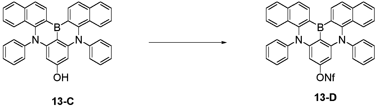
- Intermediate 13-C (3.4 g), nonafluorobutane-1-sulfonyl fluoride (2.2 g), and potassium carbonate (1.5 g) were dissolved in acetonitrile (40 ml), heated to 50 °C, and then stirred for 4 hours. After cooling to room temperature, distilled water was added to remove potassium carbonate. Thereby, Intermediate 13-D (1.6 g) was obtained.
-

- Intermediate 13-D (2.7 g), (4-(trimethylsilyl)phenyl)boronic acid (0.8 g), and potassium carbonate (1.4 g) were dissolved in 20 ml of tetrahydrofuran and 10 ml of distilled water, and tetrakis(triphenylphosphine)palladium (0.2 g) was added thereto, and then refluxed for 12 hours. After cooling to room temperature, the aqueous layer was removed, magnesium sulfate was added to the organic layer, and then filtered. After concentration, acetonitrile was added to obtain Compound 13 (0.8 g). The mass spectrum measurement of the obtained solid was measured, and as a result, a peak was confirmed at M/Z=669.
-

- Intermediate 13-D (2.7 g) was dissolved in anhydrous tetrahydrofuran (24 ml) under a nitrogen atmosphere, and the ambient temperature of the reactor was maintained at -78 °C. Then, 1.4 ml of 2.5 M-butyl lithium was slowly added dropwise. After completion of the dropwise addition, stirring was carried out for 1 hour, and then 0.7 ml of chlorotrimethylsilane was dissolved in 10 ml of purified tetrahydrofuran, and then slowly added dropwise. The reaction solution was stirred for about 1 hour while being maintained at -78 °C. Diluted hydrochloric acid was added to the reaction solution to complete the reaction, followed by liquid separation using methylene chloride. The resultant organic layer was dried with magnesium sulfate, filtered, and then distilled under reduced pressure. Column chromatography (developer: hexane/ethyl acetate=50 %/50 % (v/v)) was used to prepare Compound 14 (0.6 g). The mass spectrum of the obtained solid was measured, and as a result, a peak was confirmed at M/Z=593.
-

- 1,3-dibromonaphthalen-2-amine (13.5 g) was suspended in a sulfuric acid aqueous solution, and 6.0 g of sodium nitrite aqueous solution was added at 0 °C to perform diazotization. Thereafter, an aqueous solution of urea was added. This solution was added to a hydrochloric acid aqueous solution of CuCl2 (13.1 g) over a plurality of additions, and stirred at room temperature for 2 hours and at 60 °C for 4 hours. After completion of the reaction, liquid layers were separated and extracted using ammonia water and ethyl acetate. The resultant organic layer was dried with magnesium sulfate, filtered, and distilled under reduced pressure. The precipitated solid was washed with water and ethanol and dried to obtain Intermediate 15-A (5.4 g). The mass spectrum of the obtained solid was measured, and as a result, a peak was confirmed at M/Z=320.
-

- A flask containing Intermediate 15-A (8.0 g), bis (4-(trimethylsilyl) phenyl) amine (16.4 g), Pd(PtBu3)2 (0.2 g), NaOtBu (6.2 g), and xylene (60 ml) was heated to 130 °C and stirred for 4 hours. The reaction solution was cooled to room temperature, and water and ethyl acetate were added to separate liquid layers. The solvent was then distilled off under reduced pressure. It was purified by silica gel column chromatography (developer: hexane/ethyl acetate = 50 %/50 % (v/v)) to obtain Intermediate 15-B (4.8 g). The mass spectrum of the solid was measured, and as a result, a peak was confirmed at M/Z=786.
-

- Compound 15 (3.0 g) was obtained in the same manner as in the step 4-b for synthesizing
Compound 4, except that Intermediate 4-B (13.8 g) was changed to Intermediate 15-B (11.7 g). The mass spectrum of the obtained solid was measured, and as a result, a peak was confirmed at M/Z=759. -

- A flask containing Intermediate 3-A (41.1 g), bis (4-(trimethylsilyl)phenyl)amine (31.7 g), Pd(PtBu3)2 (0.2 g), NaOtBu (12.6 g), and xylene (130 ml) was heated to 110 °C and stirred for 4 hours. The reaction solution was cooled to room temperature, and water and ethyl acetate were added to separate liquid layers. The solvent was then distilled off under reduced pressure. It was purified by silica gel column chromatography (developer: hexane/ethyl acetate = 50 %/50 % (v/v)) to obtain Intermediate 16-A (19.8 g). The mass spectrum of the solid was measured, and as a result, a peak was confirmed at M/Z=704.
-
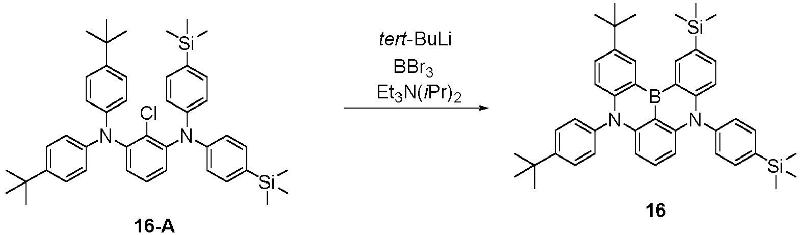
- Compound 16 (3.0 g) was obtained in the same manner as in the step 4-b for synthesizing
Compound 4, except that Intermediate 4-B (13.8 g) was changed to Intermediate 16-A (11.2 g). The mass spectrum of the obtained solid was measured, and as a result, a peak was confirmed at M/Z=677. -

- A flask containing 1-bromo-2,3-dichloro-5-methylbenzene (9.3 g), diphenylamine (6.9 g), Pd(PtBu3)2 (0.2 g), NaOtBu (6.2 g), and toluene (90 ml) was heated to 110 °C and stirred for 4 hours. The reaction solution was cooled to room temperature, and water and ethyl acetate were added to separate liquid layers. The solvent was then distilled off under reduced pressure. It was purified by silica gel column chromatography (developer: hexane/ethyl acetate= 50 %/50 % (v/v)) to obtain Intermediate 17-A (4.0 g). The mass spectrum of the solid was measured, and as a result, a peak was confirmed at M/Z=328.
-

- A flask containing Intermediate 17-A (6.6. g), bis(4-(trimethylsilyl)phenyl)amine (6.9 g), Pd(PtBu3)2 (0.2 g), NaOtBu (6.2 g), and xylene (90 ml) was heated to 130 °C and stirred for 8 hours. The reaction solution was cooled to room temperature, and water and ethyl acetate were added to separate liquid layers. The solvent was then distilled off under reduced pressure. It was purified by silica gel column chromatography (developer: hexane/ethyl acetate=50 %/50 % (v/v)) to obtain Intermediate 17-B (2.8 g). The mass spectrum of the solid was measured, and as a result, a peak was confirmed at M/Z=605.
-

- Compound 17 (1.4 g) was obtained in the same manner as in the step 4-b for synthesizing
Compound 4, except that Intermediate 4-B (13.8 g) was changed to Intermediate 17-B (9.0 g). The mass spectrum of the obtained solid was measured, and as a result, a peak was confirmed at M/Z=579. -

- Diisopropylamine (15.5 ml) was added to 200 ml of anhydrous tetrahydrofuran under a nitrogen atmosphere, and then 42.0 ml of 2.5M-butyllithium was slowly added dropwise at -78 °C. The reaction solution was stirred for about 2 hours while being maintained at -78 °C, and 43.2 g of (3,5-dibromophenyl)(methyl)diphenylsilane was dissolved in 160 ml of tetrahydrofuran, and slowly added dropwise. After stirring at -78 °C for 2 hours, an excess amount of carbon dioxide gas was added, and the temperature was gradually raised to room temperature. The diluted hydrochloric acid was added to the reaction solution to complete the reaction, and then liquid layers were separated and extracted using methylene chloride. The resultant organic layer was dried with magnesium sulfate, filtered, and then distilled under reduced pressure. Column chromatography (developer: hexane/ethyl acetate=60 %/40 % (v/v)) was used to prepare 14.6 g of 2,6-dibromo-4-(methyldiphenylsilyl)aniline.
- Subsequently, 30.2 g of 2,6-dibromo-4-(methyldiphenylsilyl)benzoic acid was dissolved in 160 ml of sulfuric acid and heated at 60 °C for 2 hours. After cooling to room temperature, sodium azide (NaN3) (8.2 g) was added thereto and was stirred at 0 °C for 48 hours. After completion of the reaction, liquid layers were separated and extracted using ammonia water and ethyl acetate. The resultant organic layer was dried with magnesium sulfate, filtered, and then distilled under reduced pressure. Column chromatography (developer: ethyl acetate) was used to prepare 14.6 g of 2,6-dibromo-4-(methyldiphenylsilyl)aniline.
- Subsequently, 2,6-dibromo-4-(methyldiphenylsilyl)aniline (19.9 g) was suspended in a sulfuric acid aqueous solution, and 6.0 g of sodium nitrite was added at 0 °C to perform diazotization. Thereafter, an aqueous solution of urea was added. This solution was added to a hydrochloric acid aqueous solution of CuCl2 (13.1 g) over a plurality of additions, and stirred at room temperature for 2 hours and at 60 °C for 4 hours. After completion of the reaction, liquid layers were separated and extracted using ammonia water and ethyl acetate. The resultant organic layer was dried with magnesium sulfate, filtered, and distilled under reduced pressure. The precipitated solid was washed with water and ethanol and dried to obtain Intermediate 18-A (7.0 g). The mass spectrum of the obtained solid was measured, and as a result, a peak was confirmed at M/Z=467.
-

- A flask containing Intermediate 18-A (11.6 g), diphenylamine (9.0 g), Pd(PtBu3)2 (0.2 g), NaOtBu (6.2 g) and xylene (70 ml) was heated to 130°C and stirred for 4 hours. The reaction solution was cooled to room temperature, and water and ethyl acetate were added to separate liquid layers. The solvent was then distilled off under reduced pressure. It was purified by silica gel column chromatography (developer: hexane/ethyl acetate=50 %/50 % (v/v)) to obtain Intermediate 18-B (4.0 g). The mass spectrum of the solid was measured, and as a result, a peak was confirmed at M/Z=643.
-

- Compound 18 (1.2 g) was obtained in the same manner as in the step 4-b for synthesizing
Compound 4, except that Intermediate 4-B (13.8 g) was changed to Intermediate 18-B (9.5 g). The mass spectrum of the obtained solid was measured, and as a result, a peak was confirmed at M/Z=617. -

- A flask containing (3,5-dibromo-4-chlorophenyl)(methyl)diphenylsilane (11.6 g), 7- methyl-N-phenyldibenzo[b,d]furan-4-amine (14.4 g), Pd(PtBu3)2 (0.2 g), NaOtBu (6.2 g), and xylene (70 ml) was heated to 130 °C and stirred for 8 hours. The reaction solution was cooled to room temperature, and water and ethyl acetate were added to separate liquid layers. The solvent was then distilled off under reduced pressure. It was purified by silica gel column chromatography (developer: hexane/ethyl acetate=50 %/50 % (v/v)) to obtain Intermediate 19-A (4.8 g). The mass spectrum of the solid was measured, and as a result, a peak was confirmed at M/Z=852.
-

- Compound 19 (1.4 g) was obtained in the same manner as in the step 4-b for synthesizing
Compound 4, except that Intermediate 4-B (13.8 g) was changed to Intermediate 19-A (12.6 g). The mass spectrum of the obtained solid was measured, and as a result, a peak was confirmed at M/Z=825. -

- A flask containing Intermediate 11-D (1.8 g), N-phenyl-4-(trimethylsilyl)aniline (0.7 g), Pd(PtBu3)2 (0.1 g), NaOtBu (3.8 g), and toluene (20 ml) was heated to 110 °C and stirred for 4 hours. The reaction solution was cooled to room temperature, and water and ethyl acetate were added to separate liquid layers. The solvent was then distilled off under reduced pressure. It was purified by silica gel column chromatography (developer: hexane/ethyl acetate=50 %/50 % (v/v)) to obtain Compound 20 (0.6 g). The mass spectrum of the solid was measured, and as a result, a peak was confirmed at M/Z=660.
- A glass substrate (Corning 7059 glass) on which a thin film of ITO (indium tin oxide) was applied to a thickness of 1000 Å was immersed into distilled water having a dispersant dissolved therein and washed by ultrasonic waves. The detergent used was a product commercially available from Fisher Co., and the distilled water was one which had been filtered twice by using a filter commercially available from Millipore Co. The ITO was washed for 30 minutes, and ultrasonic washing was then repeated twice for 10 minutes by using distilled water. After the completion of washing with distilled water, washing with ultrasonic waves was performed using isopropyl alcohol, acetone, and methanol solvent in this order, and the resulting product was dried.
- A compound of formula HAT below was thermally vacuum-deposited in a thickness of 50 Å on the prepared ITO transparent electrode to form a hole injection layer. A compound of formula HT-A below was vacuum-deposited thereon in a thickness of 1000 Å as a hole transport layer, following by vacuum deposition of a compound of formula HT-B below (100 Å). A compound BH-1 as a host and a
compound 1 prepared in Example 1 as a dopant were vacuum-deposited at a weight ratio of 98:2 to form a light emitting layer in a thickness of 200 Å. - Subsequently, a compound of formula ET-A below and the compound of formula Liq were deposited at a ratio of 1:1 in a thickness of 300 Å. Magnesium (Mg) doped with 10 wt% silver (Ag) in a thickness of 150 Å and aluminum in a thickness of 1000 Å were sequentially deposited to form a cathode. Thereby, an organic light emitting device was manufactured.
- In the above process, the vapor deposition rate of the organic material was maintained at 1 Å/s, the vapor deposition rate of LiF was maintained at 0.2 Å/s, and the vapor deposition rate of aluminum was maintained at 3 Å/s to 7 Å/s.


- The organic light emitting devices were manufactured in the same manner as in Experimental Example 1, except that the compounds shown in Table 1 below were used instead of the
compound 1 in Experimental Example 1. In Table 1 below, BH-2 means the following compound.
- The organic light emitting devices were manufactured in the same manner as in Example 1, except that the compounds shown in Table 1 below were used instead of the
compound 1 in Experimental Example 1. In Table 1 below, D-1 to D-4 mean the following compounds, respectively.

- The driving voltage, light emitting efficiency, and color coordinate (CIEy) were measured at an electric current of 10 mA/cm2 for the organic light emitting devices manufactured in Experimental Examples 1 to 22 and Comparative Experimental Examples 1 to 4, and the time (LT95) at which the luminance became 95 % relative to the initial luminance at the current density of 20 mA/cm2 was measured. The above results are shown in Table 1 below.
[Table 1] Host Dopant 10 mA/cm2 20 mA/cm2 Driving voltage (v) Efficiency (cd/A) CIEy Lifetime (h) Experimental Example 1 BH-1 Compound 1 4.4 6.0 0.100 204 Experimental Example 2 BH-1 Compound 2 4.6 6.1 0.098 206 Experimental Example 3 BH-1 Compound 3 4.5 6.0 0.096 207 Experimental Example 4 BH-1 Compound 4 4.5 6.2 0.098 224 Experimental Example 5 BH-1 Compound 5 4.6 6.3 0.097 222 Experimental Example 6 BH-1 Compound 6 4.2 6.3 0.099 208 Experimental Example 7 BH-1 Compound 7 4.2 6.2 0.098 208 Experimental Example 8 BH-1 Compound 8 4.4 6.1 0.098 221 Experimental Example 9 BH-1 Compound 9 4.4 6.2 0.094 212 Experimental Example 10 BH-1 Compound 10 4.0 6.2 0.092 210 Experimental Example 11 BH-1 Compound 11 4.2 6.3 0.094 213 Experimental Example 12 BH-1 Compound 12 4.1 6.2 0.093 214 Experimental Example 13 BH-1 Compound 13 4.4 6.3 0.098 204 Experimental Example 14 BH-1 Compound 14 4.2 6.4 0.098 203 Experimental Example 15 BH-1 Compound 15 4.3 6.0 0.098 200 Experimental Example 16 BH-1 Compound 16 4.1 6.0 0.096 209 Experimental Example 17 BH-1 Compound 17 4.3 6.1 0.098 220 Experimental Example 18 BH-1 Compound 18 4.2 6.1 0.094 202 Experimental Example 19 BH-1 Compound 19 4.2 6.1 0.098 202 Experimental Example 20 BH-1 Compound 20 4.3 6.1 0.096 201 Experimental Example 21 BH-1 +BH-2 Compound 17 4.4 6.2 0.094 222 Experimental Example 22 BH-1 +BH-2 Compound 20 4.2 6.0 0.096 204 Comparative Experimental Example 1 BH-1 D-1 4.3 5.1 0.096 164 Comparative Experimental Example 2 BH-1 D-2 4.6 5.3 0.098 156 Comparative Experimental Example 3 BH-1 D-3 4.3 5.2 0.100 153 Comparative Experimental Example 4 BH-1 D-4 4.6 5.4 0.094 159 - As shown in Table 1, it was confirmed that Experimental Examples 1 to 22 exhibited excellent efficiency and lifetime compared with Comparative Experimental Examples 1 to 4. Specifically, when comparing Experimental Examples 9, 11, and 12 with Comparative Experimental Example 1, it was confirmed that Experimental Examples 9, 11, and 12 in which a silyl group was introduced showed the tendency for the lifetime of the device to be increased by about 30 % compared to that of Comparative Experimental Example 1 in which a silyl group was not introduced. In addition, comparing Experimental Examples 6 and 14 with Comparative Experimental Example 2 and Experimental Examples 6 and 14 in which a silyl group was introduced showed the tendency that the lifetime of the device was increased by about 30 to 33 % compared with Comparative Experimental Example 1 in which a silyl group was not introduced. It was confirmed that these tendencies were similarly displayed between Experimental Example 15 and Comparative Experimental Example 3, and between Example 11 and Comparative Example 4. Therefore, in the case where the silyl group is connected to
Formula 1 of the present invention, excellent heat resistance and resistance to decomposition can be achieved. Thus, it was confirmed that a device adopting this, for example, an organic light emitting device, has high stability and a long lifetime when manufactured, stored, and driven.[Description of symbols] 1: substrate, 2: anode, 3: light emitting layer 4: cathode 5: hole injection layer 6: hole transport layer 7: light emitting layer 8: electron transport layer
Claims (17)
- A compound represented by the following Formula 1, or containing a structural unit represented by the following Formula 1:

rings A1 to A3 are each independently a C6-20 aromatic ring or a C2-60 heteroaromatic ring containing at least one heteroatom selected from the group consisting of N, O, and S,
Ra, Rb, and R1 to R3 are each independently hydrogen; deuterium; a halogen; a cyano; a nitro; a substituted or unsubstituted silyl; a substituted or unsubstituted amino; a substituted or unsubstituted C1-60 alkyl; a substituted or unsubstituted C1-60 haloalkyl; a substituted or unsubstituted C1-60 alkoxy; a substituted or unsubstituted C1-60 haloalkoxy; a substituted or unsubstituted C3-60 cycloalkyl; a substituted or unsubstituted C2-60 alkenyl; a substituted or unsubstituted C6-60 aryl; a substituted or unsubstituted C6-60 aryloxy; or a substituted or unsubstituted C2-60 heteroaryl containing at least one heteroatom selected from the group consisting of N, O, and S,
with the proviso that at least one of Ra, Rb, and R1 to R3 is a substituted or unsubstituted silyl group, or is substituted with a silyl group,
Ra is optionally connected to the ring A1 or A3 by a single bond, -O-, -S-, -C (Q1)(Q2)-, or -N(Q3)-,
Rb is optionally connected to the ring A2 or A3 by a single bond, -O-, -S-,-C(Q4)(Q5)-, or -N(Q6), and
the rings A1 and A2 are optionally connected to each other by a single bond,-O-, -S-, -C(Q7)(Q8)-, or -N(Q9)-,
wherein Q1 to Q9 are each independently hydrogen; deuterium; a C1-10 alkyl; or a C6-20 aryl, and n1 to n3 are each independently an integer of 0 to 10. - The compound of claim 1, wherein the rings A1 to A3 are each independently benzene, naphthalene, carbazole, dibenzofuran, or dibenzothiophene rings.
- The compound of claim 1, wherein the compound represented by Formula 1 is represented by one of the following Formulas 1-1 to 1-13:
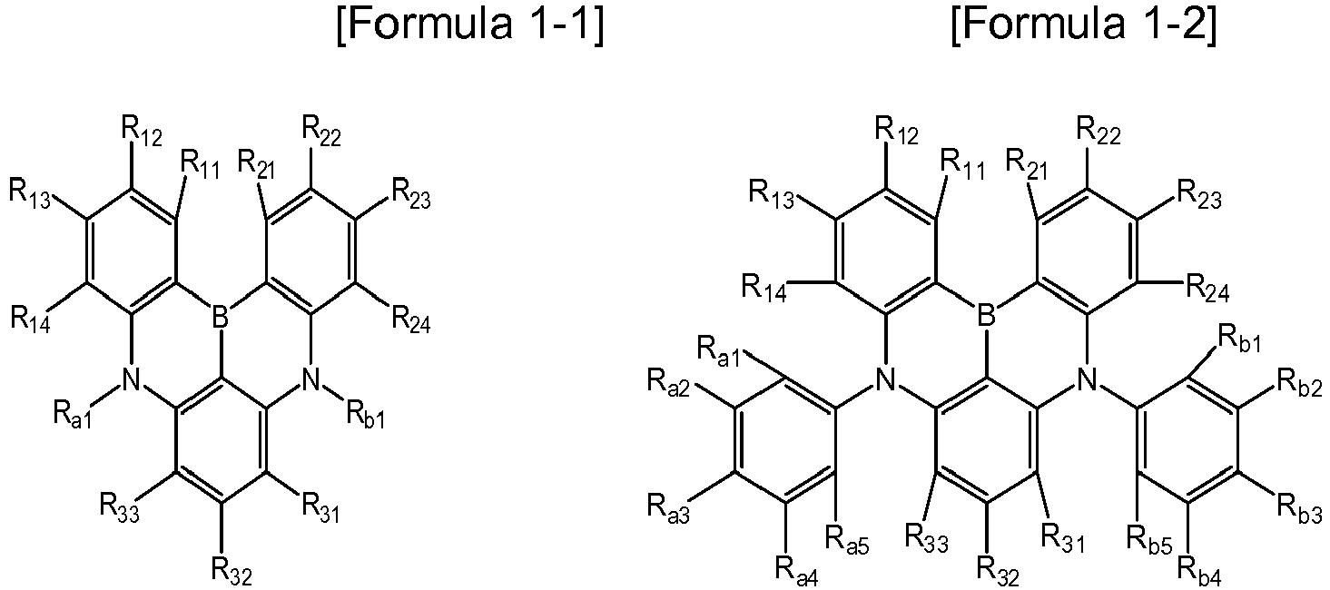


X1 and X2 are each independently O, S, or N(C6-20 aryl),
L1 to L5 are each independently a single bond, -O-, -S-, -C(C1-4 alkyl)(C1-4 alkyl)-, or -N(C6-20 aryl)-,
Ra1 to Ra6, Rb1 to Rb6, R11 to R16, R21 to R26, and R31 to R35 are each independently hydrogen; deuterium; a halogen; a substituted or unsubstituted tri(C1-20 alkyl)silyl; a substituted or unsubstituted tri(C6-20 aryl)silyl; a substituted or unsubstituted di(C6-20 aryl)amino; a substituted or unsubstituted (C6-20 aryl)(C2-20 heteroaryl)amino; a substituted or unsubstituted C1-20 alkyl; a substituted or unsubstituted C1-20 haloalkyl; a substituted or unsubstituted C1-20 alkoxy; a substituted or unsubstituted C1-20 haloalkoxy; a substituted or unsubstituted C6-20 aryl; a substituted or unsubstituted C6-20 aryloxy; or a substituted or unsubstituted C2-20 heteroaryl containing at least one heteroatom selected from the group consisting of N, O, and S, wherein adjacent substituents of Ra1 to Ra6 and Rb1 to Rb6 are optionally connected to each other to form a substituted or unsubstituted C6-20 aromatic ring,
with the proviso that at least one of Ra1 to Ra6, Rb1 to Rb6, R11 to R16, R21 to R26, and R31 to R35 in one formula is a substituted or unsubstituted tri(C1-20 alkyl)silyl group, or a substituted or unsubstituted tri(C6-20 aryl )silyl group; or is substituted by a tri(C1-20alkyl)silyl group or a tri(C6-20 aryl)silyl group. - The compound of claim 3, wherein in Formulas 1-1 to 1-13, X1 and X2 are each independently O, S, or N(C6H5).
- The compound of claim 3, wherein in Formulas 1-1 to 1-13, L1 to L4 are each independently a single bond, -O-, -S-, or -C(CH3)2 -, and L5 is -N(C6H5)-.
- The compound of claim 3, wherein in Formulas 1-1 to 1-13, at least one of Ra1 to Ra6, Rb1 to Rb6, R11 to R16, R21 to R26, and R31 to R35 is -Si(CH3)3 or -SiC6H5)3; or is substituted by -Si(CH3)3 or -Si(C6H5)3.
- The compound of claim 3, wherein in Formulas 1-1 to 1-13, Ra1 to Ra6, Rb1 to Rb6, R11 to R16, R21 to R26, and R31 to R35 are each independently hydrogen; deuterium; a halogen; -Si(CH3)3; -Si(C6H5)3; -CH3; -CH(CH3)2; -C(CH3)3; -CF3; or-OCF3; and are selected from the group consisting of:


- The compound of claim 3, wherein the compound represented by Formula 1 is represented by any one of the following Formulas 1-1A to 1-13A:


X1, X2, L1 to L5, Ra1 to Ra4, Rb1 to Rb4, R12, R13, R22, R23, and R32 are as defined in claim 3,
with the proviso that at least one of Ra1 to Ra4, Rb1 to Rb4, R12, R13, R22, R23, and R32 in one formula is -Si(CH3)3 or -Si(C6H5)3; or is substituted by -Si(CH3)3 or-Si(C6H5)3. - The compound of claim 1, wherein the compound containing a structural unit represented by Formula 1 is represented by one of the following Formulas 2-1 to 2-7:


Ra1 to Ra10, Rb1 to Rb10, R11 to R18, R21 to R28, and R31 to R36 are each independently hydrogen; deuterium; a halogen; a substituted or unsubstituted tri(C1-20alkyl)silyl; a substituted or unsubstituted C1-20 alkyl; a substituted or unsubstituted C1-20 haloalkyl; a substituted or unsubstituted C1-20 alkoxy; a substituted or unsubstituted C1-20 haloalkoxy; a substituted or unsubstituted C6-20 aryl; a substituted or unsubstituted C6-20 aryloxy; or a substituted or unsubstituted C2-20 heteroaryl containing at least one heteroatom selected from the group consisting of N, O, and S, wherein adjacent substituents of Ra1 to Ra6 and Rb1 to Rb6 are optionally connected to each other to form a substituted or unsubstituted C6-20 aromatic ring,
with the proviso that at least one of Ra1 to Ra10, Rb1 to Rb10, R11 to R18, R21 to R28, and R31 to R36 in one formula is a substituted or unsubstituted tri(C1-20 alkyl)silyl group or a substituted or unsubstituted tri(C6-20 aryl )silyl group; or is substituted by a tri(C1-20alkyl)silyl group or a tri(C6-20 aryl)silyl group. - The compound of claim 9, wherein in Formulas 2-1 to 2-7, at least one of Ra1 to Ra10, Rb1 to Rb10, R11 to R18, R21 to R28, and R31 to R36 is -Si(CH3)3, or is substituted by -Si(CH3)3.
- The compound of claim 9, wherein in Formulas 2-1 to 2-7, Ra1 to Ra10, Rb1 to Rb10, R11 to R18, R21 to R28, and R31 to R36 are each independently hydrogen,-Si(CH3)3, or -CH3.
- The compound of claim 9, wherein the compound containing a structural unit represented by Formula 1 is represented by one of the following Formulas 2-1A to 2-7A:


Ra1 to Ra3, Ra8, Rb1 to Rb3, Rb8, R12, R16, R22, R26, R32, and R35 are as defined in claim 9,
with the proviso that at least one of Ra1 to Ra3, Ra8, Rb1 to Rb3, Rb8, R12, R16, R22, R26, R32, and R35 is -Si(CH3)3, or is substituted by -Si(CH3)3. - The compound of claim 1, wherein the compound is any one selected from the group consisting of the following compounds:


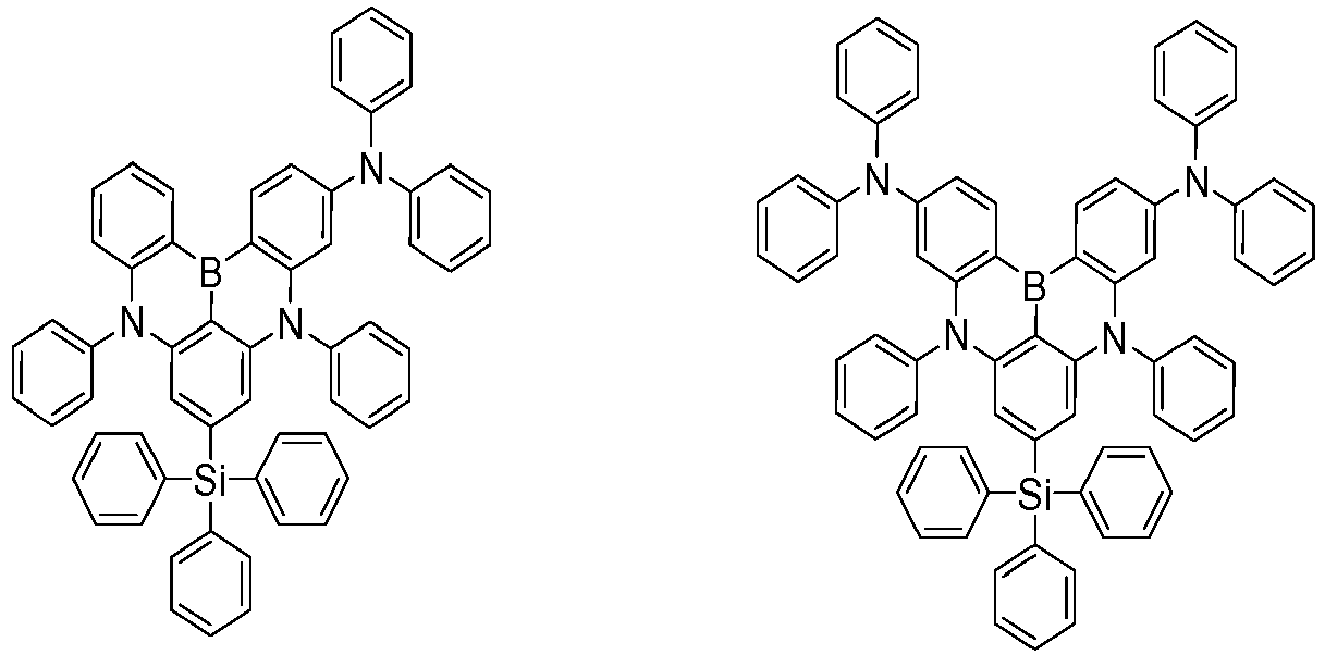


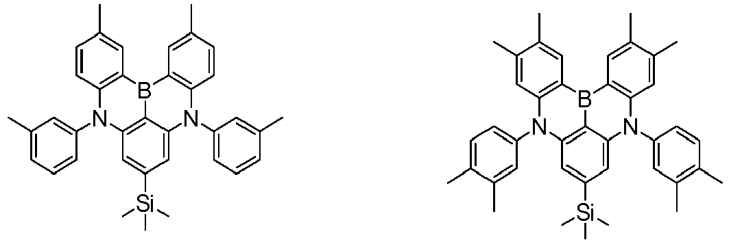


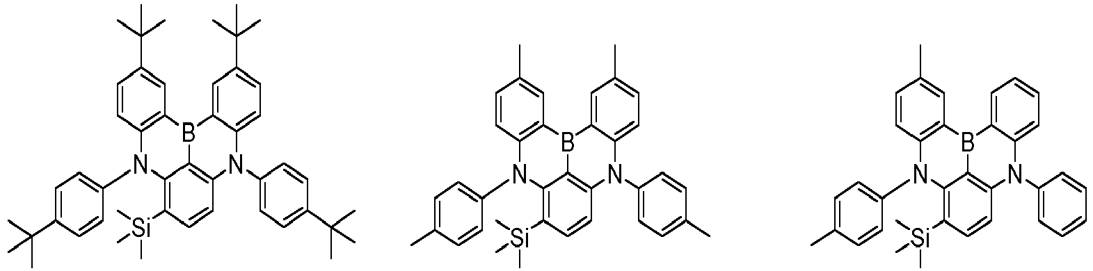


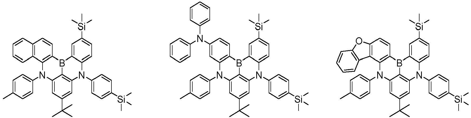


- An organic light emitting device including: a first electrode; a second electrode provided to face the first electrode; and at least one organic material layer provided between the first electrode and the second electrode, wherein at least one organic material layer includes a compound according to anyone of claims 1 to 13.
- The organic light emitting device of claim 14, wherein the organic material layer including the compound is a light emitting layer, and the light emitting layer is formed by a vacuum deposition method.
- The organic light emitting device of claim 15, wherein the compound is a dopant material, and the content of the dopant material is 0.5 to 20 % by weight with respect to the total content of the light emitting layer.
- The organic light emitting device of claim 15, wherein the light emitting layer further includes a host material, and the host material is a compound represented by the following Formula 3:

Ar is a C6-20 aryl or a C2-60 heteroaryl containing at least one heteroatom selected from the group consisting of N, O, and S, and
n is an integer of 1 to 10.
Applications Claiming Priority (2)
| Application Number | Priority Date | Filing Date | Title |
|---|---|---|---|
| KR20170056389 | 2017-05-02 | ||
| PCT/KR2018/005102 WO2018203666A1 (en) | 2017-05-02 | 2018-05-02 | Novel compound and organic light emitting device using same |
Publications (3)
| Publication Number | Publication Date |
|---|---|
| EP3564249A1 true EP3564249A1 (en) | 2019-11-06 |
| EP3564249A4 EP3564249A4 (en) | 2020-02-19 |
| EP3564249B1 EP3564249B1 (en) | 2021-01-20 |
Family
ID=64016526
Family Applications (1)
| Application Number | Title | Priority Date | Filing Date |
|---|---|---|---|
| EP18794244.6A Active EP3564249B1 (en) | 2017-05-02 | 2018-05-02 | Novel compound and organic light emitting device using same |
Country Status (7)
| Country | Link |
|---|---|
| US (1) | US11502261B2 (en) |
| EP (1) | EP3564249B1 (en) |
| JP (1) | JP6907440B2 (en) |
| KR (1) | KR102053324B1 (en) |
| CN (1) | CN110225917B (en) |
| TW (1) | TWI672311B (en) |
| WO (1) | WO2018203666A1 (en) |
Cited By (7)
| Publication number | Priority date | Publication date | Assignee | Title |
|---|---|---|---|---|
| EP3819959A1 (en) * | 2019-11-07 | 2021-05-12 | Samsung Display Co., Ltd. | Organic electroluminescence device |
| WO2021151532A1 (en) * | 2020-01-28 | 2021-08-05 | Cynora Gmbh | Organic molecules for optoelectronic devices |
| JP2021172603A (en) * | 2020-04-22 | 2021-11-01 | 出光興産株式会社 | Compound, material for organic electroluminescent device, organic electroluminescent device, and electronic apparatus |
| WO2022078961A1 (en) * | 2020-10-12 | 2022-04-21 | Cynora Gmbh | Organic molecules for optoelectronic devices |
| EP4001284A4 (en) * | 2019-07-17 | 2023-07-19 | SFC Co., Ltd. | NOVEL BORON COMPOUND AND ORGANIC LIGHT EMITTING DEVICE THEREOF |
| EP4273151A4 (en) * | 2021-03-09 | 2024-07-03 | Lg Chem, Ltd. | Novel compound and organic light emitting device using same |
| EP4265625A4 (en) * | 2021-03-09 | 2024-07-03 | Lg Chem, Ltd. | NOVEL COMPOUND AND ORGANIC LIGHT-EMITTING DEVICE THEREOF |
Families Citing this family (145)
| Publication number | Priority date | Publication date | Assignee | Title |
|---|---|---|---|---|
| KR20220084200A (en) * | 2016-04-26 | 2022-06-21 | 가꼬우 호징 관세이 가쿠잉 | Organic Electroluminescence Device |
| US10686141B2 (en) | 2016-09-07 | 2020-06-16 | Kwansei Gakuin Educational Foundation | Polycyclic aromatic compound |
| KR101876763B1 (en) * | 2017-05-22 | 2018-07-11 | 머티어리얼사이언스 주식회사 | Organic compound and organic electroluminescent device comprising the same |
| JP7276750B2 (en) * | 2017-10-13 | 2023-05-18 | 学校法人関西学院 | Polycyclic aromatic dimer compounds |
| US12146087B2 (en) | 2017-12-28 | 2024-11-19 | Idemitsu Kosan Co., Ltd. | Compound and organic electroluminescence device |
| WO2019198698A1 (en) * | 2018-04-12 | 2019-10-17 | 学校法人関西学院 | Fluorine-substituted polycyclic aromatic compound |
| KR102575479B1 (en) | 2018-07-31 | 2023-09-08 | 삼성디스플레이 주식회사 | Organic electroluminescence device and polycyclic compound for organic electroluminescence device |
| CN113169285A (en) * | 2018-08-23 | 2021-07-23 | 学校法人关西学院 | Organic electroluminescent element, display device, lighting device, composition for forming light-emitting layer, and compound |
| CN109346614B (en) * | 2018-08-31 | 2020-01-31 | 昆山国显光电有限公司 | organic electroluminescent device and display device |
| WO2020080528A1 (en) * | 2018-10-18 | 2020-04-23 | 学校法人関西学院 | Polycyclic aromatic compound |
| KR102640489B1 (en) * | 2018-11-16 | 2024-02-26 | 에스에프씨 주식회사 | Novel boron compounds and Organic light emitting diode including the same |
| WO2020105990A1 (en) * | 2018-11-19 | 2020-05-28 | 에스에프씨 주식회사 | Novel boron compound and organic light-emitting device comprising same |
| KR102640485B1 (en) * | 2018-11-20 | 2024-02-26 | 에스에프씨 주식회사 | Novel boron compounds and Organic light emitting diode including the same |
| US11456428B2 (en) * | 2018-11-21 | 2022-09-27 | Sfc Co., Ltd. | Indolocarbazole derivatives and organic electroluminescent devices using the same |
| KR102202111B1 (en) * | 2018-11-21 | 2021-01-12 | 에스에프씨 주식회사 | Indolocarbazole derivatives and organoelectroluminescent device using the same |
| US20230059210A1 (en) * | 2018-11-29 | 2023-02-23 | Merck Patent Gmbh | Electronic device |
| KR102094830B1 (en) | 2018-11-30 | 2020-03-30 | 에스에프씨 주식회사 | Polycyclic aromatic compound and organoelectroluminescent device using the same |
| US11985891B2 (en) | 2018-11-30 | 2024-05-14 | Sfc Co., Ltd. | Polycyclic aromatic compounds and organic electroluminescent devices using the same |
| WO2020111830A1 (en) * | 2018-11-30 | 2020-06-04 | 에스에프씨 주식회사 | Organic light-emitting element using polycyclic aromatic derivative compound |
| KR102623053B1 (en) * | 2018-12-05 | 2024-01-10 | 삼성디스플레이 주식회사 | Organic electroluminescence device and polycyclic compound for organic electroluminescence device |
| KR102745916B1 (en) | 2018-12-10 | 2024-12-26 | 삼성디스플레이 주식회사 | Organic electroluminescence device and polycyclic compound for organic electroluminescence device |
| KR102316064B1 (en) * | 2018-12-26 | 2021-10-22 | 주식회사 엘지화학 | Compound and organic light emitting device comprising the same |
| KR102331456B1 (en) | 2018-12-27 | 2021-11-26 | 주식회사 엘지화학 | Compound and organic light emitting device comprising the same |
| CN111377955A (en) * | 2018-12-29 | 2020-07-07 | 江苏三月光电科技有限公司 | A kind of boron-containing compound, its preparation method and its application |
| WO2020135790A1 (en) * | 2018-12-29 | 2020-07-02 | 江苏三月光电科技有限公司 | Boron-containing compound and application thereof to organic light-emitting device |
| WO2020145725A1 (en) * | 2019-01-11 | 2020-07-16 | 주식회사 엘지화학 | Compound and organic light-emitting element comprising same |
| CN112888695B (en) * | 2019-01-18 | 2023-12-22 | 株式会社Lg化学 | Compounds and organic light-emitting diodes containing the same |
| EP3686206B1 (en) * | 2019-01-23 | 2021-10-27 | Cynora Gmbh | Organic molecules for optoelectronic devices |
| JP2020123721A (en) * | 2019-01-29 | 2020-08-13 | 学校法人関西学院 | Organic electroluminescent device and display device |
| WO2020167001A1 (en) * | 2019-02-13 | 2020-08-20 | 주식회사 엘지화학 | Boron-containing compound, and organic light-emitting element comprising same |
| KR102324962B1 (en) * | 2019-02-15 | 2021-11-11 | 주식회사 엘지화학 | Organic light emitting device |
| US12006335B2 (en) | 2019-03-08 | 2024-06-11 | Lg Chem, Ltd. | Heterocyclic compound and organic light emitting device comprising same |
| EP3947399A1 (en) * | 2019-03-29 | 2022-02-09 | cynora GmbH | Organic molecules for optoelectronic devices |
| WO2020201070A1 (en) * | 2019-04-01 | 2020-10-08 | Cynora Gmbh | Organic molecules for optoelectronic devices |
| KR102776379B1 (en) * | 2019-04-09 | 2025-03-10 | 삼성디스플레이 주식회사 | Condensed-cyclic compound and organic light emittind device including the same |
| KR102770946B1 (en) | 2019-04-12 | 2025-02-24 | 삼성디스플레이 주식회사 | Organic electroluminescence device and polycyclic compound for organic electroluminescence device |
| KR102352576B1 (en) * | 2019-04-15 | 2022-01-18 | 머티어리얼사이언스 주식회사 | An organic compound and an organic light emitting diode |
| EP3959215A1 (en) | 2019-04-26 | 2022-03-02 | Idemitsu Kosan Co., Ltd. | Polycyclic compound and an organic electroluminescence device comprising the polycyclic compound or the composition |
| US12065454B2 (en) | 2019-05-13 | 2024-08-20 | Samsung Display Co., Ltd. | Organic molecules for optoelectronic devices |
| CN111943966B (en) * | 2019-05-14 | 2024-10-18 | 北京鼎材科技有限公司 | Compound, thermal activation delay fluorescent material, organic electroluminescent device and application thereof |
| KR102666982B1 (en) * | 2019-05-20 | 2024-05-20 | 삼성디스플레이 주식회사 | Compound and Organic light emitting device comprising same |
| CN112028912B (en) * | 2019-06-03 | 2024-07-12 | 北京鼎材科技有限公司 | A new type of boron-containing organic electroluminescent material and its application |
| KR20200139287A (en) | 2019-06-03 | 2020-12-14 | 삼성디스플레이 주식회사 | Organic electroluminescence device and fused polycyclic compound for organic electroluminescence device |
| CN112047967A (en) * | 2019-06-07 | 2020-12-08 | 学校法人关西学院 | Polycyclic aromatic compound, reactive compound, polymer compound, pendant polymer compound, and uses using the same |
| CN113906036B (en) * | 2019-06-11 | 2024-10-25 | 学校法人关西学院 | Polycyclic aromatic compound, material for organic device, organic electroluminescent element, and display device or lighting device |
| US12552984B2 (en) | 2019-06-12 | 2026-02-17 | Sfc Co., Ltd. | Organic electroluminescent device |
| KR102191018B1 (en) * | 2019-06-12 | 2020-12-14 | 에스에프씨 주식회사 | Organic electroluminescent device |
| KR102796253B1 (en) * | 2019-06-13 | 2025-04-17 | 삼성디스플레이 주식회사 | Heterocyclic compound and organic light emitting device comprising the same |
| JP7624646B2 (en) * | 2019-06-13 | 2025-01-31 | 学校法人関西学院 | Polycyclic aromatic compounds |
| TWI869412B (en) * | 2019-06-14 | 2025-01-11 | 學校法人關西學院 | Polycyclic aromatic compound or polymer of polycyclic aromatic compound, reactive compound, polymer compound or polymer crosslinked product, suspended polymer compound or suspended polymer crosslinked product, material for organic element, composition, organic electroluminescent element, display device or lighting device, and method for producing polycyclic aromatic compound or polymer of polycyclic aromatic compound |
| KR102785333B1 (en) | 2019-06-19 | 2025-03-26 | 삼성디스플레이 주식회사 | Organic electroluminescence device and fused polycyclic compound for organic electroluminescence device |
| KR102657477B1 (en) * | 2019-07-18 | 2024-04-12 | 칭화 유니버시티 | New compounds and their applications and organic electroluminescent devices using the compounds |
| CN110407858B (en) * | 2019-07-18 | 2020-07-14 | 清华大学 | A novel compound and its application and organic electroluminescent device using the compound |
| KR102733856B1 (en) * | 2019-07-25 | 2024-11-27 | 삼성디스플레이 주식회사 | Organic molecules for optoelectronic devices |
| KR102880247B1 (en) | 2019-07-30 | 2025-11-04 | 삼성디스플레이 주식회사 | Organic electroluminescence device and polycyclic compound for organic electroluminescence device |
| KR102391296B1 (en) * | 2019-07-31 | 2022-04-27 | 주식회사 엘지화학 | Organic light emitting device |
| KR102239440B1 (en) | 2019-07-31 | 2021-04-13 | 주식회사 엘지화학 | Multicyclic compound and organic light emitting device comprising the same |
| CN113228331B (en) * | 2019-07-31 | 2024-08-02 | 株式会社Lg化学 | Organic light emitting device |
| KR102406148B1 (en) * | 2019-07-31 | 2022-06-08 | 주식회사 엘지화학 | Organic light emitting device |
| CN113454092B (en) * | 2019-07-31 | 2024-06-14 | 株式会社Lg化学 | Compound and organic light-emitting device containing the same |
| WO2021020943A1 (en) * | 2019-07-31 | 2021-02-04 | 주식회사 엘지화학 | Organic light-emitting device |
| WO2021020929A1 (en) * | 2019-08-01 | 2021-02-04 | 주식회사 엘지화학 | Compound and organic light emitting device comprising same |
| KR102890854B1 (en) * | 2019-08-12 | 2025-11-27 | 삼성디스플레이 주식회사 | Organic electroluminescence device and fused polycyclic compound for organic electroluminescence device |
| CN110627822A (en) * | 2019-10-08 | 2019-12-31 | 吉林大学 | A green-light narrow-spectrum tricoordinate boron luminescent compound, luminescent composition and application thereof |
| WO2021075856A1 (en) * | 2019-10-14 | 2021-04-22 | 에스에프씨 주식회사 | Polycyclic compound and organic light-emitting device using same |
| CN112679531B (en) * | 2019-10-18 | 2025-02-18 | 北京鼎材科技有限公司 | Boron-containing compound and organic electroluminescent device containing the same |
| CN110729418B (en) * | 2019-10-23 | 2022-06-03 | 昆山国显光电有限公司 | Organic electroluminescent device and display device |
| US11919914B2 (en) | 2019-10-25 | 2024-03-05 | Universal Display Corporation | Organic electroluminescent materials and devices |
| CN120463729A (en) | 2019-10-25 | 2025-08-12 | 环球展览公司 | Organic electroluminescent materials and devices |
| KR102352160B1 (en) * | 2019-10-31 | 2022-01-19 | 에스에프씨 주식회사 | Polycyclic compound and organoelectro luminescent device using the same |
| CN112778309B (en) * | 2019-11-06 | 2022-08-12 | 广州华睿光电材料有限公司 | N-containing condensed ring compound and application thereof in organic electronic device |
| WO2021090619A1 (en) * | 2019-11-08 | 2021-05-14 | 富士フイルム株式会社 | Photoelectric conversion element, imaging element, optical sensor, material for photoelectric conversion elements, and compound |
| CN110790782A (en) * | 2019-11-11 | 2020-02-14 | 北京大学深圳研究生院 | Dark blue organic luminescent material and preparation method and application thereof |
| JP7376892B2 (en) * | 2019-11-18 | 2023-11-09 | 学校法人関西学院 | Polycyclic aromatic compounds |
| CN110981899B (en) * | 2019-11-20 | 2023-02-03 | 苏州久显新材料有限公司 | Polycyclic organoboron derivatives and electronic devices |
| KR102815240B1 (en) | 2019-11-25 | 2025-06-04 | 삼성디스플레이 주식회사 | Condensed-cyclic compound and organic light emitting device including the same |
| CN113795497B (en) | 2019-11-29 | 2024-04-26 | 株式会社Lg化学 | Compound and organic light emitting device comprising the same |
| CN113853377B (en) * | 2019-11-29 | 2024-05-14 | 株式会社Lg化学 | Heterocyclic compound and organic light-emitting device comprising same |
| KR20210067845A (en) | 2019-11-29 | 2021-06-08 | 주식회사 엘지화학 | Compound and organic light emitting device comprising same |
| KR102477844B1 (en) | 2019-11-29 | 2022-12-15 | 주식회사 엘지화학 | Organic light emitting device |
| KR102526907B1 (en) * | 2019-11-29 | 2023-04-28 | 주식회사 엘지화학 | Polycyclic compound and organic light emitting device comprising same |
| WO2021107681A1 (en) * | 2019-11-29 | 2021-06-03 | 주식회사 엘지화학 | Compound and organic light-emitting device comprising same |
| WO2021107680A1 (en) * | 2019-11-29 | 2021-06-03 | 주식회사 엘지화학 | Compound and organic light-emitting element comprising same |
| US11856853B2 (en) * | 2019-12-03 | 2023-12-26 | Lg Display Co., Ltd. | Organic compound, organic light emitting diode and organic light emitting device including the compound |
| KR102806106B1 (en) | 2019-12-10 | 2025-05-13 | 삼성디스플레이 주식회사 | Organic electroluminescence device and polycyclic compound for organic electroluminescence device |
| CN112940023B (en) * | 2019-12-11 | 2025-02-21 | 北京鼎材科技有限公司 | An organic compound and its application and an organic electroluminescent device using the same |
| KR102908941B1 (en) | 2019-12-13 | 2026-01-09 | 삼성디스플레이 주식회사 | Organic electroluminescence device and fused polycyclic compound for organic electroluminescence device |
| CN112341482B (en) * | 2019-12-27 | 2024-01-09 | 广东聚华印刷显示技术有限公司 | Organic compound, polymer, mixture, composition and electronic device |
| CN112500298B (en) * | 2019-12-27 | 2022-03-04 | 陕西莱特光电材料股份有限公司 | Arylamine compound and organic electroluminescent device |
| WO2021141378A1 (en) * | 2020-01-06 | 2021-07-15 | 에스에프씨 주식회사 | Polycyclic aromatic derivative compound and organoelectroluminescent device using same |
| KR102815486B1 (en) | 2020-01-17 | 2025-06-02 | 삼성디스플레이 주식회사 | Organic electroluminescence device and fused polycyclic compound for organic electroluminescence device |
| KR102703930B1 (en) * | 2020-01-23 | 2024-09-06 | 에스에프씨 주식회사 | Novel Organic compounds and Organic light emitting diode including the same |
| KR102752780B1 (en) | 2020-02-18 | 2025-01-13 | 삼성디스플레이 주식회사 | Organic electroluminescence device and polycyclic compound for organic electroluminescence device |
| KR102720071B1 (en) | 2020-02-26 | 2024-10-23 | 삼성디스플레이 주식회사 | Compound and light emitting device comprising the same |
| EP3876296A1 (en) * | 2020-03-05 | 2021-09-08 | Samsung Electronics Co., Ltd. | Organic light-emitting device |
| KR102819805B1 (en) | 2020-03-19 | 2025-06-13 | 삼성디스플레이 주식회사 | Organic electroluminescence device and condensed cyclic compound for organic electroluminescence device |
| TW202138542A (en) * | 2020-03-31 | 2021-10-16 | 日商日鐵化學材料股份有限公司 | Organic electroluminescent element |
| US20230159566A1 (en) * | 2020-04-16 | 2023-05-25 | Sfc Co., Ltd. | Novel boron compound and organic light-emitting diode comprising same |
| JP7658987B2 (en) * | 2020-04-22 | 2025-04-08 | 三星ディスプレイ株式會社 | Organic molecules, use of organic molecules, compositions, optoelectronic devices and methods for producing optoelectronic devices |
| KR102847865B1 (en) | 2020-05-28 | 2025-08-20 | 삼성디스플레이 주식회사 | Organic electroluminescence device and polycyclic compound for organic electroluminescence device |
| KR102836100B1 (en) | 2020-05-28 | 2025-07-21 | 삼성디스플레이 주식회사 | Organic electroluminescence device and polycyclic compound for organic electroluminescence device |
| KR102798044B1 (en) | 2020-06-15 | 2025-04-22 | 삼성디스플레이 주식회사 | Organic light emitting device and electronic apparatus including the same |
| KR102895074B1 (en) * | 2020-07-02 | 2025-12-02 | 주식회사 엘지화학 | Novel compound and organic light emitting device comprising the same |
| KR102866750B1 (en) * | 2020-07-02 | 2025-09-30 | 삼성디스플레이 주식회사 | condensed cyclic compound and light emitting device including the same |
| CN113880869A (en) * | 2020-07-02 | 2022-01-04 | 北京鼎材科技有限公司 | Compound, application thereof and organic electroluminescent device comprising compound |
| EP4185655B1 (en) * | 2020-07-24 | 2024-05-29 | Samsung Display Co., Ltd. | Organic molecules for optoelectronic devices |
| JP7634219B2 (en) * | 2020-09-07 | 2025-02-21 | 学校法人関西学院 | Polycyclic aromatic compounds |
| CN114181235B (en) * | 2020-09-14 | 2024-10-15 | 北京夏禾科技有限公司 | Polycyclic compounds and their devices |
| US12284905B2 (en) | 2020-10-06 | 2025-04-22 | Samsung Display Co., Ltd. | Light emitting device |
| CN116390959A (en) * | 2020-10-14 | 2023-07-04 | 浙江光昊光电科技有限公司 | A kind of high polymer, composition comprising it, organic photoelectric device and application |
| WO2022085590A1 (en) * | 2020-10-20 | 2022-04-28 | 日鉄ケミカル&マテリアル株式会社 | Light-emitting material, and organic electroluminescent element |
| KR102892095B1 (en) | 2020-11-05 | 2025-11-27 | 삼성디스플레이 주식회사 | Condensed cyclic compound, organic light emitting device including the same and electronic device including the organic light emitting device |
| KR102533896B1 (en) * | 2020-11-09 | 2023-05-18 | 경희대학교 산학협력단 | Boron-based compound and organic light emitting device comprising the same |
| KR102874469B1 (en) * | 2020-11-11 | 2025-10-22 | 삼성디스플레이 주식회사 | Electroluminescence device |
| KR102849800B1 (en) * | 2020-11-26 | 2025-08-22 | 주식회사 엘지화학 | Compound and organic light emitting device comprising same |
| KR20220084871A (en) * | 2020-12-14 | 2022-06-21 | 솔루스첨단소재 주식회사 | Organic light-emitting compound and organic electroluminescent device using the same |
| KR20220086224A (en) * | 2020-12-16 | 2022-06-23 | 솔루스첨단소재 주식회사 | Organic light-emitting compound and organic electroluminescent device using the same |
| TW202242069A (en) * | 2020-12-23 | 2022-11-01 | 日商三菱化學股份有限公司 | Organic electroluminescent element, organic el display device, organic el lighting, and organic electroluminescent element production method |
| CN112707926B (en) * | 2020-12-29 | 2021-10-22 | 华南理工大学 | Red electroluminescent compound and preparation method and application thereof |
| KR20220094622A (en) * | 2020-12-29 | 2022-07-06 | 엘지디스플레이 주식회사 | Emitting compound and orgnic light emitting device including the same |
| KR102799317B1 (en) * | 2021-01-04 | 2025-04-21 | 주식회사 엘지화학 | Organic light emitting device |
| KR102939860B1 (en) | 2021-02-17 | 2026-03-16 | 삼성디스플레이 주식회사 | Light-emitting device including condensed-cyclic compound and electronic device including the same |
| KR102875407B1 (en) * | 2021-03-11 | 2025-10-22 | 주식회사 엘지화학 | Compound and organic light emitting device comprising same |
| CN115073503A (en) * | 2021-03-12 | 2022-09-20 | Sfc株式会社 | Polycyclic compound and organic electroluminescent device using the same |
| KR102914864B1 (en) | 2021-03-17 | 2026-01-19 | 삼성디스플레이 주식회사 | Light emitting device including heterocyclic compound and electronic apparatus including the light emitting device |
| KR20220131464A (en) * | 2021-03-19 | 2022-09-28 | 삼성디스플레이 주식회사 | light emitting element |
| KR20220157176A (en) * | 2021-05-20 | 2022-11-29 | 주식회사 엘지화학 | Novel compound and organic light emitting device comprising the same |
| US12552816B2 (en) | 2021-05-26 | 2026-02-17 | Samsung Display Co., Ltd. | Light emitting diode |
| CN113527345B (en) * | 2021-07-02 | 2026-01-30 | 常州大学 | Spirochiral boron-nitrogen-based CPMR-TADF luminescent materials and their applications |
| JP7386937B2 (en) * | 2021-07-12 | 2023-11-27 | エスエフシー カンパニー リミテッド | Polycyclic compounds and organic light-emitting devices using the same |
| KR20230010573A (en) * | 2021-07-12 | 2023-01-19 | 에스에프씨 주식회사 | Organic light-emitting device |
| KR20230014930A (en) | 2021-07-21 | 2023-01-31 | 삼성디스플레이 주식회사 | Light emitting device |
| CN113788852A (en) * | 2021-09-03 | 2021-12-14 | 清华大学 | Luminescent material, application thereof and organic electroluminescent device comprising luminescent material |
| CN116082377B (en) * | 2021-11-03 | 2025-07-29 | 江苏三月科技股份有限公司 | Organic compound based on boron-nitrogen condensed rings and organic electroluminescent device prepared from organic compound |
| CN113999256A (en) * | 2021-11-26 | 2022-02-01 | 中国科学技术大学 | Boron-containing organic compound and light-emitting device |
| KR20230085645A (en) * | 2021-12-07 | 2023-06-14 | 삼성전자주식회사 | Heterocyclic compound, organic light emitting device including the same and electronic apparatus including the organic light emitting device |
| CN116354998B (en) * | 2021-12-27 | 2025-05-16 | 广州华睿光电材料有限公司 | Organic compounds, mixtures, compositions and organic electronic devices |
| CN116410217B (en) * | 2021-12-28 | 2025-07-11 | 广州华睿光电材料有限公司 | Organic compound and mixture, composition and organic electronic device comprising the same |
| CN116444549B (en) * | 2022-07-19 | 2026-03-17 | 广东阿格蕾雅光电材料有限公司 | Organic electroluminescent materials and their applications |
| CN115322213B (en) * | 2022-08-31 | 2023-05-30 | 季华恒烨(佛山)电子材料有限公司 | Boron-nitrogen compound, synthesis method, light-emitting layer, light-emitting device and electronic equipment |
| CN115850317B (en) * | 2022-12-13 | 2024-02-13 | 常州大学 | MR-HLCT near ultraviolet luminescent material and application thereof in OLEDs |
| CN116284084B (en) * | 2023-03-14 | 2026-03-24 | 清华大学 | A luminescent material, its application, and an organic electroluminescent device comprising the same. |
| CN116947898A (en) * | 2023-03-30 | 2023-10-27 | 宇瑞(上海)化学有限公司 | Boron nitrogen compound and organic electronic device using same |
| CN116693564A (en) * | 2023-05-29 | 2023-09-05 | 季华恒烨(佛山)电子材料有限公司 | A kind of boron nitrogen compound and its preparation method and application |
| CN117624216B (en) * | 2023-11-30 | 2025-09-16 | 京东方科技集团股份有限公司 | Organic compound containing boron and nitrogen and application thereof in organic electroluminescent device |
Family Cites Families (15)
| Publication number | Priority date | Publication date | Assignee | Title |
|---|---|---|---|---|
| KR100430549B1 (en) | 1999-01-27 | 2004-05-10 | 주식회사 엘지화학 | New organomattalic complex molecule for the fabrication of organic light emitting diodes |
| DE10135513B4 (en) | 2001-07-20 | 2005-02-24 | Novaled Gmbh | Light-emitting component with organic layers |
| KR100874472B1 (en) | 2007-02-28 | 2008-12-18 | 에스에프씨 주식회사 | Blue light emitting compound and organic light emitting device using the same |
| US20090053557A1 (en) * | 2007-08-23 | 2009-02-26 | Spindler Jeffrey P | Stabilized white-emitting oled device |
| JP2011243597A (en) | 2010-05-14 | 2011-12-01 | Toyo Ink Sc Holdings Co Ltd | Material for organic electroluminescent element and its use |
| WO2012118164A1 (en) | 2011-03-03 | 2012-09-07 | 国立大学法人九州大学 | Novel compound, charge transport material, and organic device |
| JP5724588B2 (en) | 2011-04-28 | 2015-05-27 | コニカミノルタ株式会社 | ORGANIC ELECTROLUMINESCENT ELEMENT MATERIAL, ORGANIC ELECTROLUMINESCENT ELEMENT, DISPLAY DEVICE AND LIGHTING DEVICE |
| US9365364B1 (en) | 2013-07-19 | 2016-06-14 | RWM Technologies, LLC | Controlled acceleration and transfer of items via a rotating platform |
| US9991455B2 (en) | 2013-09-20 | 2018-06-05 | Idemitsu Kosan Co., Ltd. | Amine compound and organic electroluminescent element |
| TWI636056B (en) | 2014-02-18 | 2018-09-21 | 學校法人關西學院 | Polycyclic aromatic compound and method for production the same, material for organic device and application thereof |
| US10374166B2 (en) | 2014-02-18 | 2019-08-06 | Kwansei Gakuin Educational Foundation | Polycyclic aromatic compound |
| TWI688137B (en) | 2015-03-24 | 2020-03-11 | 學校法人關西學院 | Organic electric field light-emitting element, display device and lighting device |
| JP6696971B2 (en) * | 2015-03-25 | 2020-05-20 | 学校法人関西学院 | Polycyclic aromatic compound and composition for forming light emitting layer |
| CN106467554A (en) * | 2016-07-29 | 2017-03-01 | 江苏三月光电科技有限公司 | A kind of boracic organic electroluminescent compounds and its application |
| KR102438956B1 (en) * | 2016-12-16 | 2022-08-31 | 가꼬우 호징 관세이 가쿠잉 | Polyaromatic Amino Compounds |
-
2018
- 2018-05-02 KR KR1020180050787A patent/KR102053324B1/en active Active
- 2018-05-02 US US16/487,420 patent/US11502261B2/en active Active
- 2018-05-02 TW TW107114941A patent/TWI672311B/en active
- 2018-05-02 JP JP2019546122A patent/JP6907440B2/en active Active
- 2018-05-02 WO PCT/KR2018/005102 patent/WO2018203666A1/en not_active Ceased
- 2018-05-02 CN CN201880008911.5A patent/CN110225917B/en active Active
- 2018-05-02 EP EP18794244.6A patent/EP3564249B1/en active Active
Cited By (10)
| Publication number | Priority date | Publication date | Assignee | Title |
|---|---|---|---|---|
| EP4001284A4 (en) * | 2019-07-17 | 2023-07-19 | SFC Co., Ltd. | NOVEL BORON COMPOUND AND ORGANIC LIGHT EMITTING DEVICE THEREOF |
| EP3819959A1 (en) * | 2019-11-07 | 2021-05-12 | Samsung Display Co., Ltd. | Organic electroluminescence device |
| US11581492B2 (en) | 2019-11-07 | 2023-02-14 | Samsung Display Co., Ltd. | Organic electroluminescence device and polycyclic compound for organic electroluminescence device |
| WO2021151532A1 (en) * | 2020-01-28 | 2021-08-05 | Cynora Gmbh | Organic molecules for optoelectronic devices |
| JP2023511709A (en) * | 2020-01-28 | 2023-03-22 | 三星ディスプレイ株式會社 | Organic molecules for optoelectronic devices |
| JP2021172603A (en) * | 2020-04-22 | 2021-11-01 | 出光興産株式会社 | Compound, material for organic electroluminescent device, organic electroluminescent device, and electronic apparatus |
| US12289995B2 (en) | 2020-04-22 | 2025-04-29 | Idemitsu Kosan Co., Ltd. | Compound, material for organic electroluminescent element, organic electroluminescent element and electronic device |
| WO2022078961A1 (en) * | 2020-10-12 | 2022-04-21 | Cynora Gmbh | Organic molecules for optoelectronic devices |
| EP4273151A4 (en) * | 2021-03-09 | 2024-07-03 | Lg Chem, Ltd. | Novel compound and organic light emitting device using same |
| EP4265625A4 (en) * | 2021-03-09 | 2024-07-03 | Lg Chem, Ltd. | NOVEL COMPOUND AND ORGANIC LIGHT-EMITTING DEVICE THEREOF |
Also Published As
| Publication number | Publication date |
|---|---|
| JP6907440B2 (en) | 2021-07-21 |
| US20200058885A1 (en) | 2020-02-20 |
| JP2020512303A (en) | 2020-04-23 |
| EP3564249B1 (en) | 2021-01-20 |
| CN110225917B (en) | 2022-11-25 |
| TWI672311B (en) | 2019-09-21 |
| EP3564249A4 (en) | 2020-02-19 |
| CN110225917A (en) | 2019-09-10 |
| KR102053324B1 (en) | 2019-12-06 |
| KR20180122298A (en) | 2018-11-12 |
| TW201843165A (en) | 2018-12-16 |
| US11502261B2 (en) | 2022-11-15 |
| WO2018203666A1 (en) | 2018-11-08 |
Similar Documents
| Publication | Publication Date | Title |
|---|---|---|
| EP3564249B1 (en) | Novel compound and organic light emitting device using same | |
| EP3757110B1 (en) | Heterocyclic compound and organic light-emitting device comprising same | |
| EP3392242B1 (en) | Novel heterocyclic compound and organic light-emitting device using same | |
| EP3835299B1 (en) | Novel heterocyclic compound and organic light emitting device using same | |
| EP3567032B1 (en) | Heterocyclic compound and organic light-emitting element utilizing same | |
| EP3862350B1 (en) | Novel compound and organic light emitting device using same | |
| EP4400501B1 (en) | Novel compound and organic light emitting device comprising same | |
| EP3498804A1 (en) | Organic light emitting device | |
| EP3620449A1 (en) | Novel compound and organic light-emitting element using same | |
| EP3327024B1 (en) | Heterocyclic compound and organic light emitting diode comprising same | |
| JP7172000B2 (en) | Novel heterocyclic compound and organic light-emitting device using the same | |
| EP3567026A1 (en) | Novel compound and organic light-emitting device using same | |
| EP3556750B1 (en) | Novel compound and organic light-emitting element including same | |
| EP3539953B1 (en) | Novel compound and organic light-emitting device using same | |
| EP3415585A1 (en) | Organic light-emitting element | |
| EP3527564A1 (en) | Novel heterocyclic compound and organic light emitting element using same | |
| EP3327008B1 (en) | Heterocyclic compound and organic light emitting element using same | |
| EP3372593A1 (en) | Novel compound and organic light emitting element comprising same | |
| KR20210023254A (en) | Novel compound and organic light emitting device comprising the same | |
| JP2024503474A (en) | Novel compounds and organic light-emitting devices using them | |
| JP2024500965A (en) | Novel compounds and organic light-emitting devices using them | |
| EP3747873B1 (en) | Novel compound and organic light emitting diode using same | |
| KR102629455B1 (en) | Novel compound and organic light emitting device comprising the same | |
| EP4242205B1 (en) | Novel compound and organic light emitting device comprising same | |
| EP4446318A1 (en) | Novel compound and organic light-emitting device comprising same |
Legal Events
| Date | Code | Title | Description |
|---|---|---|---|
| STAA | Information on the status of an ep patent application or granted ep patent |
Free format text: STATUS: THE INTERNATIONAL PUBLICATION HAS BEEN MADE |
|
| PUAI | Public reference made under article 153(3) epc to a published international application that has entered the european phase |
Free format text: ORIGINAL CODE: 0009012 |
|
| STAA | Information on the status of an ep patent application or granted ep patent |
Free format text: STATUS: REQUEST FOR EXAMINATION WAS MADE |
|
| 17P | Request for examination filed |
Effective date: 20190801 |
|
| AK | Designated contracting states |
Kind code of ref document: A1 Designated state(s): AL AT BE BG CH CY CZ DE DK EE ES FI FR GB GR HR HU IE IS IT LI LT LU LV MC MK MT NL NO PL PT RO RS SE SI SK SM TR |
|
| AX | Request for extension of the european patent |
Extension state: BA ME |
|
| A4 | Supplementary search report drawn up and despatched |
Effective date: 20200116 |
|
| RIC1 | Information provided on ipc code assigned before grant |
Ipc: C07F 7/08 20060101ALI20200110BHEP Ipc: C07F 5/02 20060101ALI20200110BHEP Ipc: H01L 51/50 20060101ALI20200110BHEP Ipc: H01L 51/00 20060101ALI20200110BHEP Ipc: C07F 19/00 20060101AFI20200110BHEP |
|
| DAV | Request for validation of the european patent (deleted) | ||
| DAX | Request for extension of the european patent (deleted) | ||
| GRAP | Despatch of communication of intention to grant a patent |
Free format text: ORIGINAL CODE: EPIDOSNIGR1 |
|
| STAA | Information on the status of an ep patent application or granted ep patent |
Free format text: STATUS: GRANT OF PATENT IS INTENDED |
|
| INTG | Intention to grant announced |
Effective date: 20201022 |
|
| GRAS | Grant fee paid |
Free format text: ORIGINAL CODE: EPIDOSNIGR3 |
|
| GRAA | (expected) grant |
Free format text: ORIGINAL CODE: 0009210 |
|
| STAA | Information on the status of an ep patent application or granted ep patent |
Free format text: STATUS: THE PATENT HAS BEEN GRANTED |
|
| AK | Designated contracting states |
Kind code of ref document: B1 Designated state(s): AL AT BE BG CH CY CZ DE DK EE ES FI FR GB GR HR HU IE IS IT LI LT LU LV MC MK MT NL NO PL PT RO RS SE SI SK SM TR |
|
| REG | Reference to a national code |
Ref country code: GB Ref legal event code: FG4D |
|
| REG | Reference to a national code |
Ref country code: CH Ref legal event code: EP |
|
| REG | Reference to a national code |
Ref country code: DE Ref legal event code: R096 Ref document number: 602018012129 Country of ref document: DE |
|
| REG | Reference to a national code |
Ref country code: AT Ref legal event code: REF Ref document number: 1356313 Country of ref document: AT Kind code of ref document: T Effective date: 20210215 |
|
| REG | Reference to a national code |
Ref country code: IE Ref legal event code: FG4D |
|
| REG | Reference to a national code |
Ref country code: NL Ref legal event code: MP Effective date: 20210120 |
|
| REG | Reference to a national code |
Ref country code: LT Ref legal event code: MG9D |
|
| REG | Reference to a national code |
Ref country code: AT Ref legal event code: MK05 Ref document number: 1356313 Country of ref document: AT Kind code of ref document: T Effective date: 20210120 |
|
| PG25 | Lapsed in a contracting state [announced via postgrant information from national office to epo] |
Ref country code: NO Free format text: LAPSE BECAUSE OF FAILURE TO SUBMIT A TRANSLATION OF THE DESCRIPTION OR TO PAY THE FEE WITHIN THE PRESCRIBED TIME-LIMIT Effective date: 20210420 Ref country code: PT Free format text: LAPSE BECAUSE OF FAILURE TO SUBMIT A TRANSLATION OF THE DESCRIPTION OR TO PAY THE FEE WITHIN THE PRESCRIBED TIME-LIMIT Effective date: 20210520 Ref country code: LT Free format text: LAPSE BECAUSE OF FAILURE TO SUBMIT A TRANSLATION OF THE DESCRIPTION OR TO PAY THE FEE WITHIN THE PRESCRIBED TIME-LIMIT Effective date: 20210120 Ref country code: BG Free format text: LAPSE BECAUSE OF FAILURE TO SUBMIT A TRANSLATION OF THE DESCRIPTION OR TO PAY THE FEE WITHIN THE PRESCRIBED TIME-LIMIT Effective date: 20210420 Ref country code: FI Free format text: LAPSE BECAUSE OF FAILURE TO SUBMIT A TRANSLATION OF THE DESCRIPTION OR TO PAY THE FEE WITHIN THE PRESCRIBED TIME-LIMIT Effective date: 20210120 Ref country code: GR Free format text: LAPSE BECAUSE OF FAILURE TO SUBMIT A TRANSLATION OF THE DESCRIPTION OR TO PAY THE FEE WITHIN THE PRESCRIBED TIME-LIMIT Effective date: 20210421 Ref country code: HR Free format text: LAPSE BECAUSE OF FAILURE TO SUBMIT A TRANSLATION OF THE DESCRIPTION OR TO PAY THE FEE WITHIN THE PRESCRIBED TIME-LIMIT Effective date: 20210120 |
|
| PG25 | Lapsed in a contracting state [announced via postgrant information from national office to epo] |
Ref country code: AT Free format text: LAPSE BECAUSE OF FAILURE TO SUBMIT A TRANSLATION OF THE DESCRIPTION OR TO PAY THE FEE WITHIN THE PRESCRIBED TIME-LIMIT Effective date: 20210120 Ref country code: RS Free format text: LAPSE BECAUSE OF FAILURE TO SUBMIT A TRANSLATION OF THE DESCRIPTION OR TO PAY THE FEE WITHIN THE PRESCRIBED TIME-LIMIT Effective date: 20210120 Ref country code: PL Free format text: LAPSE BECAUSE OF FAILURE TO SUBMIT A TRANSLATION OF THE DESCRIPTION OR TO PAY THE FEE WITHIN THE PRESCRIBED TIME-LIMIT Effective date: 20210120 Ref country code: LV Free format text: LAPSE BECAUSE OF FAILURE TO SUBMIT A TRANSLATION OF THE DESCRIPTION OR TO PAY THE FEE WITHIN THE PRESCRIBED TIME-LIMIT Effective date: 20210120 Ref country code: SE Free format text: LAPSE BECAUSE OF FAILURE TO SUBMIT A TRANSLATION OF THE DESCRIPTION OR TO PAY THE FEE WITHIN THE PRESCRIBED TIME-LIMIT Effective date: 20210120 |
|
| PG25 | Lapsed in a contracting state [announced via postgrant information from national office to epo] |
Ref country code: IS Free format text: LAPSE BECAUSE OF FAILURE TO SUBMIT A TRANSLATION OF THE DESCRIPTION OR TO PAY THE FEE WITHIN THE PRESCRIBED TIME-LIMIT Effective date: 20210520 |
|
| REG | Reference to a national code |
Ref country code: DE Ref legal event code: R026 Ref document number: 602018012129 Country of ref document: DE |
|
| PLBI | Opposition filed |
Free format text: ORIGINAL CODE: 0009260 |
|
| PG25 | Lapsed in a contracting state [announced via postgrant information from national office to epo] |
Ref country code: SM Free format text: LAPSE BECAUSE OF FAILURE TO SUBMIT A TRANSLATION OF THE DESCRIPTION OR TO PAY THE FEE WITHIN THE PRESCRIBED TIME-LIMIT Effective date: 20210120 Ref country code: EE Free format text: LAPSE BECAUSE OF FAILURE TO SUBMIT A TRANSLATION OF THE DESCRIPTION OR TO PAY THE FEE WITHIN THE PRESCRIBED TIME-LIMIT Effective date: 20210120 Ref country code: CZ Free format text: LAPSE BECAUSE OF FAILURE TO SUBMIT A TRANSLATION OF THE DESCRIPTION OR TO PAY THE FEE WITHIN THE PRESCRIBED TIME-LIMIT Effective date: 20210120 |
|
| PLAX | Notice of opposition and request to file observation + time limit sent |
Free format text: ORIGINAL CODE: EPIDOSNOBS2 |
|
| 26 | Opposition filed |
Opponent name: VEREENIGDE OCTROOIBUREAUX N.V. Effective date: 20211018 |
|
| PG25 | Lapsed in a contracting state [announced via postgrant information from national office to epo] |
Ref country code: DK Free format text: LAPSE BECAUSE OF FAILURE TO SUBMIT A TRANSLATION OF THE DESCRIPTION OR TO PAY THE FEE WITHIN THE PRESCRIBED TIME-LIMIT Effective date: 20210120 Ref country code: SK Free format text: LAPSE BECAUSE OF FAILURE TO SUBMIT A TRANSLATION OF THE DESCRIPTION OR TO PAY THE FEE WITHIN THE PRESCRIBED TIME-LIMIT Effective date: 20210120 Ref country code: RO Free format text: LAPSE BECAUSE OF FAILURE TO SUBMIT A TRANSLATION OF THE DESCRIPTION OR TO PAY THE FEE WITHIN THE PRESCRIBED TIME-LIMIT Effective date: 20210120 |
|
| REG | Reference to a national code |
Ref country code: CH Ref legal event code: PL |
|
| PG25 | Lapsed in a contracting state [announced via postgrant information from national office to epo] |
Ref country code: ES Free format text: LAPSE BECAUSE OF FAILURE TO SUBMIT A TRANSLATION OF THE DESCRIPTION OR TO PAY THE FEE WITHIN THE PRESCRIBED TIME-LIMIT Effective date: 20210120 Ref country code: CH Free format text: LAPSE BECAUSE OF NON-PAYMENT OF DUE FEES Effective date: 20210531 Ref country code: AL Free format text: LAPSE BECAUSE OF FAILURE TO SUBMIT A TRANSLATION OF THE DESCRIPTION OR TO PAY THE FEE WITHIN THE PRESCRIBED TIME-LIMIT Effective date: 20210120 Ref country code: MC Free format text: LAPSE BECAUSE OF FAILURE TO SUBMIT A TRANSLATION OF THE DESCRIPTION OR TO PAY THE FEE WITHIN THE PRESCRIBED TIME-LIMIT Effective date: 20210120 Ref country code: LU Free format text: LAPSE BECAUSE OF NON-PAYMENT OF DUE FEES Effective date: 20210502 Ref country code: LI Free format text: LAPSE BECAUSE OF NON-PAYMENT OF DUE FEES Effective date: 20210531 |
|
| REG | Reference to a national code |
Ref country code: BE Ref legal event code: MM Effective date: 20210531 |
|
| PLBB | Reply of patent proprietor to notice(s) of opposition received |
Free format text: ORIGINAL CODE: EPIDOSNOBS3 |
|
| PG25 | Lapsed in a contracting state [announced via postgrant information from national office to epo] |
Ref country code: SI Free format text: LAPSE BECAUSE OF FAILURE TO SUBMIT A TRANSLATION OF THE DESCRIPTION OR TO PAY THE FEE WITHIN THE PRESCRIBED TIME-LIMIT Effective date: 20210120 |
|
| PG25 | Lapsed in a contracting state [announced via postgrant information from national office to epo] |
Ref country code: IT Free format text: LAPSE BECAUSE OF FAILURE TO SUBMIT A TRANSLATION OF THE DESCRIPTION OR TO PAY THE FEE WITHIN THE PRESCRIBED TIME-LIMIT Effective date: 20210120 Ref country code: IE Free format text: LAPSE BECAUSE OF NON-PAYMENT OF DUE FEES Effective date: 20210502 |
|
| PG25 | Lapsed in a contracting state [announced via postgrant information from national office to epo] |
Ref country code: IS Free format text: LAPSE BECAUSE OF FAILURE TO SUBMIT A TRANSLATION OF THE DESCRIPTION OR TO PAY THE FEE WITHIN THE PRESCRIBED TIME-LIMIT Effective date: 20210520 |
|
| PG25 | Lapsed in a contracting state [announced via postgrant information from national office to epo] |
Ref country code: BE Free format text: LAPSE BECAUSE OF NON-PAYMENT OF DUE FEES Effective date: 20210531 |
|
| REG | Reference to a national code |
Ref country code: DE Ref legal event code: R100 Ref document number: 602018012129 Country of ref document: DE |
|
| PLCK | Communication despatched that opposition was rejected |
Free format text: ORIGINAL CODE: EPIDOSNREJ1 |
|
| PG25 | Lapsed in a contracting state [announced via postgrant information from national office to epo] |
Ref country code: NL Free format text: LAPSE BECAUSE OF NON-PAYMENT OF DUE FEES Effective date: 20210120 Ref country code: CY Free format text: LAPSE BECAUSE OF FAILURE TO SUBMIT A TRANSLATION OF THE DESCRIPTION OR TO PAY THE FEE WITHIN THE PRESCRIBED TIME-LIMIT Effective date: 20210120 |
|
| PG25 | Lapsed in a contracting state [announced via postgrant information from national office to epo] |
Ref country code: HU Free format text: LAPSE BECAUSE OF FAILURE TO SUBMIT A TRANSLATION OF THE DESCRIPTION OR TO PAY THE FEE WITHIN THE PRESCRIBED TIME-LIMIT; INVALID AB INITIO Effective date: 20180502 |
|
| PLBN | Opposition rejected |
Free format text: ORIGINAL CODE: 0009273 |
|
| STAA | Information on the status of an ep patent application or granted ep patent |
Free format text: STATUS: OPPOSITION REJECTED |
|
| 27O | Opposition rejected |
Effective date: 20230209 |
|
| PG25 | Lapsed in a contracting state [announced via postgrant information from national office to epo] |
Ref country code: MK Free format text: LAPSE BECAUSE OF FAILURE TO SUBMIT A TRANSLATION OF THE DESCRIPTION OR TO PAY THE FEE WITHIN THE PRESCRIBED TIME-LIMIT Effective date: 20210120 |
|
| PG25 | Lapsed in a contracting state [announced via postgrant information from national office to epo] |
Ref country code: TR Free format text: LAPSE BECAUSE OF FAILURE TO SUBMIT A TRANSLATION OF THE DESCRIPTION OR TO PAY THE FEE WITHIN THE PRESCRIBED TIME-LIMIT Effective date: 20210120 |
|
| PG25 | Lapsed in a contracting state [announced via postgrant information from national office to epo] |
Ref country code: MT Free format text: LAPSE BECAUSE OF FAILURE TO SUBMIT A TRANSLATION OF THE DESCRIPTION OR TO PAY THE FEE WITHIN THE PRESCRIBED TIME-LIMIT Effective date: 20210120 |
|
| P01 | Opt-out of the competence of the unified patent court (upc) registered |
Free format text: CASE NUMBER: UPC_APP_325506/2023 Effective date: 20230523 |
|
| PGFP | Annual fee paid to national office [announced via postgrant information from national office to epo] |
Ref country code: DE Payment date: 20250422 Year of fee payment: 8 |
|
| PGFP | Annual fee paid to national office [announced via postgrant information from national office to epo] |
Ref country code: FR Payment date: 20250422 Year of fee payment: 8 |
|
| PGFP | Annual fee paid to national office [announced via postgrant information from national office to epo] |
Ref country code: GB Payment date: 20260324 Year of fee payment: 9 |