EP3564192B1 - System und verfahren zur steuerung einer vorrichtung zur behandlung von abwasser - Google Patents
System und verfahren zur steuerung einer vorrichtung zur behandlung von abwasser Download PDFInfo
- Publication number
- EP3564192B1 EP3564192B1 EP18759839.6A EP18759839A EP3564192B1 EP 3564192 B1 EP3564192 B1 EP 3564192B1 EP 18759839 A EP18759839 A EP 18759839A EP 3564192 B1 EP3564192 B1 EP 3564192B1
- Authority
- EP
- European Patent Office
- Prior art keywords
- signal
- sewage treatment
- chip microcomputer
- single chip
- pump
- Prior art date
- Legal status (The legal status is an assumption and is not a legal conclusion. Google has not performed a legal analysis and makes no representation as to the accuracy of the status listed.)
- Active
Links
Images
Classifications
-
- C—CHEMISTRY; METALLURGY
- C02—TREATMENT OF WATER, WASTE WATER, SEWAGE, OR SLUDGE
- C02F—TREATMENT OF WATER, WASTE WATER, SEWAGE, OR SLUDGE
- C02F1/00—Treatment of water, waste water, or sewage
- C02F1/008—Control or steering systems not provided for elsewhere in subclass C02F
-
- C—CHEMISTRY; METALLURGY
- C02—TREATMENT OF WATER, WASTE WATER, SEWAGE, OR SLUDGE
- C02F—TREATMENT OF WATER, WASTE WATER, SEWAGE, OR SLUDGE
- C02F3/00—Biological treatment of water, waste water, or sewage
- C02F3/30—Aerobic and anaerobic processes
-
- C—CHEMISTRY; METALLURGY
- C02—TREATMENT OF WATER, WASTE WATER, SEWAGE, OR SLUDGE
- C02F—TREATMENT OF WATER, WASTE WATER, SEWAGE, OR SLUDGE
- C02F2203/00—Apparatus and plants for the biological treatment of water, waste water or sewage
- C02F2203/006—Apparatus and plants for the biological treatment of water, waste water or sewage details of construction, e.g. specially adapted seals, modules, connections
-
- C—CHEMISTRY; METALLURGY
- C02—TREATMENT OF WATER, WASTE WATER, SEWAGE, OR SLUDGE
- C02F—TREATMENT OF WATER, WASTE WATER, SEWAGE, OR SLUDGE
- C02F2209/00—Controlling or monitoring parameters in water treatment
- C02F2209/22—O2
-
- C—CHEMISTRY; METALLURGY
- C02—TREATMENT OF WATER, WASTE WATER, SEWAGE, OR SLUDGE
- C02F—TREATMENT OF WATER, WASTE WATER, SEWAGE, OR SLUDGE
- C02F2209/00—Controlling or monitoring parameters in water treatment
- C02F2209/42—Liquid level
-
- C—CHEMISTRY; METALLURGY
- C02—TREATMENT OF WATER, WASTE WATER, SEWAGE, OR SLUDGE
- C02F—TREATMENT OF WATER, WASTE WATER, SEWAGE, OR SLUDGE
- C02F2209/00—Controlling or monitoring parameters in water treatment
- C02F2209/44—Time
-
- C—CHEMISTRY; METALLURGY
- C02—TREATMENT OF WATER, WASTE WATER, SEWAGE, OR SLUDGE
- C02F—TREATMENT OF WATER, WASTE WATER, SEWAGE, OR SLUDGE
- C02F2301/00—General aspects of water treatment
- C02F2301/04—Flow arrangements
- C02F2301/046—Recirculation with an external loop
Definitions
- the present disclosure relates to the technical field of water treatment, in particular, to a control system and method of a sewage treatment device.
- small sewage device regardless of being used for the treatment of domestic sewage (in more cases) or of sewage from small manufacturing enterprises (in less cases), usually has non-uniform amount of inflow water and water quality, and is unable to avoid the direct influence of daily change of water amount on the system, which has a large impact on the system, directly affecting the treatment process and effect, and significantly affecting the growth of microorganisms for the small devices adopting the biological treatment methods, and many deficiencies still exist even when the device is operated periodically according to traditional daily routines.
- Examples of small scale sewage treatment devices are disclosed in CN 105 776 515 A , AU 557 608 B2 and EP 2 070 877 A1 .
- an object of the present disclosure includes providing a control system and method of a sewage treatment device, in order to overcome one of the problems of modelization and poor variable impact resistance of existing small sewage treatment devices, to improve the stability of control system and achieve an energy conservation effect.
- the present invention provides a control system of a sewage treatment device according to claim 1.
- the present invention further provides a control method of sewage treatment device according to claim 6.
- the examples of the present disclosure bring at least the following beneficial effects: for the control system and method of sewage treatment device provided by the present disclosure, the single chip microcomputer, and the lift pump and the gas pump which are connected respectively to the single chip microcomputer are included; the lift pump triggers the first switching signal according to the height of water level, wherein the first switching signal includes the starting signal and the shutdown signal; the single chip microcomputer regulates and controls according to the starting signal the delay time of starting to run the gas pump, and generates the delay start signal; alternatively, the single chip microcomputer regulates and controls according to the shutdown signal the delay time of stopping running of the gas pump, and generates the delay stop signal; the gas pump is controlled to perform the aeration and the backflow according to the delay start signal and the delay stop signal.
- the present disclosure can overcome the problems of modelization and poor variable impact resistance of the existing small sewage treatment devices, improve the stability of control system, and achieve an energy conservation effect.
- the small sewage treatment device reduces the inconvenience of pipe network construction and the cost input.
- the treatment capacity of small sewage treatment device is typically suitable for a shared use by several to dozens of households, with no regulating pool being arranged for keeping the small sewage treatment device's advantages of small occupied area and simple construction.
- small sewage device regardless of being used for the treatment of domestic sewage or of sewage from small manufacturing enterprise, usually has non-uniform amount of inflow water and water quality and is unable to avoid the direct influence from daily change of water amount on the system, which has a large impact on the system, directly affecting the treatment process and effect, and significantly affecting the growth of microorganisms for the small devices adopting the biological treatment methods, and many deficiencies still exist even when the device is operated periodically according to traditional daily routines.
- control system and method of sewage treatment device provided in the examples of the present disclosure can overcome the problems of modelization and poor variable impact resistance of existing small sewage treatment devices, to improve the stability of control system and achieve an energy conservation effect.
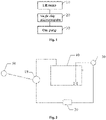
- Fig.1 is a schematic view of a control system of sewage treatment device provided in Example 1 of the present disclosure.
- the control system of sewage treatment device includes: a single chip microcomputer 20, and a lift pump 10 and a gas pump 30 which are connected respectively to the single chip microcomputer 20, and the control system further includes a user end device 50 and a sewage treatment device 40.
- the sewage treatment device 40 herein is a small sewage treatment device.
- the user end device 50 is connected to the lift pump 10 and gathers, through a pipe network, water discharged by users and enables it to flow by gravity into a pool body where the lift pump 10 is located.
- An amount of water treated by the user end device 50 ranges from 0.5m3/d to 200m3/d.
- the user end device 50 simply gathers and collects the water discharged from several to dozens of households, to a discharge outlet and enables it to flow by gravity to a small pool where the lift pump 10 is located, with a simple pipe network and a short distance, ensuring the treatment amount within a small range.
- the lift pump 10 is provided with a floating ball, and the floating ball controls the switch of the lift pump 10 according to a height of water level in the pool body, and further triggers a first switching signal.
- the lift pump 10 itself has a floating ball, and is arranged in a pool body of small volume and small occupied area.
- the floating ball rises with the height of water level by buoyancy to further control the lift pump 10 to turn on the switch automatically, and to pump sewage to the sewage treatment device 40.
- this lift pump 10 is connected to the single chip microcomputer 20, and the single chip microcomputer 20 receives its first switching signal and supplies electricity thereto.
- the single chip microcomputer 20 acquires the first switching signal and regulates and controls a running mode of the gas pump 30 according to the first switching signal, and generates a second switching control signal.
- the gas pump 30 is controlled to perform aeration and backflow according to the second switching control signal.
- the single chip microcomputer 20 regulates and controls a running state of the gas pump 30 by judging a running state of the lift pump 10.
- the first switching signal is divided into a starting signal and a shutdown signal, its corresponding second switching control signal includes a delay start signal and a delay stop signal.
- the single chip microcomputer 20 regulates and controls according to the starting signal the delay time of starting to run the gas pump 30, and generates a delay start signal.
- the single chip microcomputer 20 regulates and controls according to the shutdown signal the delay time of stopping running of the gas pump 30, and generates a delay stop signal.
- the floating ball can be connected through a flexible cable to a mechanical switch mounted on the lift pump.
- a mechanical switch mounted on the lift pump.
- an electronic liquid level switch is adopted to replace the floating ball.
- the water level is detected by a built-in electronic probe, and a detected signal is then processed by a chip.
- the chip When the water is judged to have reached a predetermined height, the chip outputs a high level, for example 24V or 5V, etc. (type PNP and type NPN are both acceptable).
- the chip When the water is judged to be lower than a predetermined height, the chip outputs a low level, for example 0V.
- Signals at high and low levels are read by a single chip microcomputer (the high level is equivalent to the starting signal, and the low level is equivalent to the shutdown signal).
- the single chip microcomputer drives the lift pump to work, and when the single chip microcomputer has read a low level, the single chip microcomputer does not drive the lift pump to work.
- the single chip microcomputer 20 controls the gas pump 30 to be also in the running state.
- the single chip microcomputer 20 regulates and controls the gas pump 30 to make it stop running automatically after delaying for a certain period of time (such as half an hour), i.e., emitting a delay stop signal to the gas pump 30.
- the single chip microcomputer 20 regulates and controls the gas pump 30 to make it start to run automatically after delaying for a certain period of time (such as ten minutes), i.e., emitting a delay start signal to the gas pump 30.
- the single chip microcomputer 20 By using the single chip microcomputer 20 to regulate and control the running of the gas pump 30 according to the running state of the lift pump 10, the amount, interval (time period) and delay time of aeration or backflow are controlled, thereby ensuring that when there is no water inflow and the nutrition is insufficient in the small sewage treatment device, avoiding the drawback of aerobic microorganism's internal consumption caused by the continue aeration in aerobic zone and keeping the organisms in a good state, and meanwhile also achieving effects of reducing invalid running time of the gas pump 30 and saving electric energy.
- the single chip microcomputer 20 is chosen as a control main body, which is adapted better to the characteristics of the small sewage treatment device, leading to a reduced bulkiness and a more compact and flexible overall arrangement.
- the gas pump 30 is respectively connected to an aeration zone and a gas lifting zone in the sewage treatment device 40 through two gas pipes, and regulates, according to the second switching control signal, valves on the gas pipes to perform aeration and backflow, to provide muddy water of aerobic aeration and gas lift backflow to the system.
- the gas pump 30 is provided outside the small sewage treatment device, has a longer service life and is connected to the small sewage treatment device through gas pipes.
- the gas pipes are provided with small valves, and by regulating the valves, the amount of aeration and the amount of backflow are enabled to be reasonable and stable.
- the valves can be electronic control valves, and the number of the valves is in data connection with the single chip microcomputers.
- the single chip microcomputer can control the valve's opening degree or control the number of valves in open state, so as to control the amount of aeration and the amount of backflow.
- the sewage treatment device 40 is a small sewage treatment device of small overall volume and compact structural arrangement.
- the sewage treatment scale of the small sewage treatment device is matched with the scale of the user end device 50.
- Biological treatment methods are often adopted for sewage treatment to make discharge water reach its required standards, wherein the biological treatment methods include AO (Anoxic-Oxic) technology and A2O (Anaerobic-Anoxic-Oxic) technology.
- the sewage treatment device includes an aeration zone and a gas lifting zone.
- the treatment measure of muddy water of aerobic aeration and gas lift backflow is provided by the gas pump 30.
- the control system of the sewage treatment device is for small sewage treatment device.
- the start and stop of the lift pump is combined with the start and stop of the gas pump by the single chip microcomputer, so as to reasonably control aeration and backflow and to maintain the stability of microorganism production in the system, hence the small sewage treatment device's capacity of resisting the variable impact of incoming water is greatly enhanced, thus ensuring the effectiveness of the system.
- the invalid running time of the gas pump is greatly reduced, making the control method more flexible and pertinent, and also achieving the object of saving electric energy.
- the single chip microcomputer which is selected as the control main body, is adapted better to the characteristics of small sewage treatment device compared with the traditional control by PLC, thus leading to a reduced bulkiness and a more compact and flexible overall arrangement.
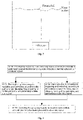
- Fig. 4 is a flow diagram of a control method of a sewage treatment device provided in Example 2 of the present disclosure.
- an example of the present disclosure further provides a control method of a sewage treatment device.
- the control method of sewage treatment device includes steps as follows:
- the starting signal is triggered; and when the water level is detected to be lower than the predetermined height, the shutdown signal is triggered.
- the single chip microcomputer After receiving the starting signal, the single chip microcomputer emits a delay start signal after a first predetermined time period.
- the single chip microcomputer After receiving the shutdown signal, the single chip microcomputer emits a delay stop signal after a second predetermined time period.
- the control system and method of the sewage treatment device includes the single chip microcomputer, and the lift pump and the gas pump which are connected respectively to the single chip microcomputer; the lift pump triggers the first switching signal according to the height of water level, wherein the first switching signal includes the starting signal and the shutdown signal; the single chip microcomputer regulates and controls according to the starting signal the delay time of starting to run the gas pump, and generates the delay start signal; alternatively, the single chip microcomputer regulates and controls according to the shutdown signal the delay time of stopping running of the gas pump, and generates the delay stop signal; the gas pump is controlled to perform the aeration and the backflow according to the delay start signal and the delay stop signal.
- the present disclosure can overcome the problems of modelization and poor variable impact resistance of the existing small sewage treatment devices, improve the stability of the control system and achieve an energy conservation effect.
- An example of the present application not being part of the invention further provides an electronic device including a memory and a processor, wherein computer program runnable on the processor are stored in the memory, and when executing the computer program, the processor performs the steps of the control method of sewage treatment device provided in the above example.
- An example of the present application not being part of the application further provides a computer readable storage medium, wherein computer programs are stored in the computer readable storage medium, and when the computer programs are executed by the processor, the steps of the control method of the sewage treatment device provided in the above example are performed.
- connection can be a fixed connection, a detachable connection, or an integrated connection; it can be a mechanical connection, or an electrical connection; it can be a direct connection or an indirect connection through an intermediate medium; and it also can also be an inner communication between two elements.
- connection can be a fixed connection, a detachable connection, or an integrated connection; it can be a mechanical connection, or an electrical connection; it can be a direct connection or an indirect connection through an intermediate medium; and it also can also be an inner communication between two elements.
- orientational or positional relationships indicated by terms such as “central”, “upper”, “lower”, “left”, “right”, “vertical”, “horizontal”, “inner” and “outer” are based on orientational or positional relationships as shown in the figures, merely for facilitating describing the present disclosure and simplifying the description, rather than indicating or implying that related devices or elements have to be in the specific orientation or to be configured and operated in specific the orientation, therefore, they should not be construed as limiting the present disclosure.
- terms such as “first”, “second” and “third” are merely for descriptive purpose, but should not be construed as indicating or implying importance in relativity.
- a computer program product of the control method of a sewage treatment device includes computer readable storage medium in which non-volatile program codes executable by a processor are stored, wherein instructions included in the program codes can be used for executing the method described in the previous method example, whose specific implementation can refer to the example of method, which will not be repeated here.
- the disclosed systems, devices and methods can also be realized in other ways.
- the above described examples of devices are merely illustrative, for example, the division of the units is merely a division of logic function, and other division ways may exist in actual implementation.
- multiple units or elements can be combined or can be integrated into another system, or some features can be omitted or not executed.
- the displayed or discussed inter coupling or direct coupling or communication can be communication or indirect coupling of communication interfaces, devices or units, and can be electrical, mechanical or in other forms.
- the units described as separate components may be or may not be physically separated, and components displayed as units may be or may not be physical units, which means that, they can be located in one place or can be distributed to multiple network units. Some or all of these units can be selected according to actual requirements to realize the object of example scheme.
- the above functions are implemented in form of software function units and are used or sold as individual products, they can be stored in a non-volatile computer readable storage medium which is executable by processor.
- the technical solution of the present disclosure essentially or the part contributing to the prior art or a part of the technical solution can be embodied in form of a software product
- the computer software product which is stored in a storage medium includes a number of instructions to allow a computer device (which could be a personal computer, a server or a network device, etc.) to execute some of or all of the steps of the method described in the examples of the present disclosure.
- the above-mentioned storage medium includes: U disk, mobile hard disk, ROM (Read-Only Memory), RAM (Random Access Memory), diskette or optical disk or other types of medium which is able to store program codes.
- the single chip microcomputer, and the lift pump and the gas pump which are connected respectively to the single chip microcomputer are included; the lift pump triggers the first switching signal according to the height of water level, wherein the first switching signal includes the starting signal and the shutdown signal; the single chip microcomputer regulates and controls according to the starting signal the delay time of starting to run the gas pump, and generates the delay start signal; alternatively, the single chip microcomputer regulates and controls according to the shutdown signal the delay time of stopping running the gas pump, and generates the delay stop signal; the gas pump is controlled to perform aeration and backflow according to the delay start signal and the delay stop signal.
- the present disclosure can overcome the problems of modelization and poor variable impact resistance of the existing small sewage treatment devices, improve the stability of control system, and achieve an energy conservation effect.
Landscapes
- Life Sciences & Earth Sciences (AREA)
- Hydrology & Water Resources (AREA)
- Engineering & Computer Science (AREA)
- Environmental & Geological Engineering (AREA)
- Water Supply & Treatment (AREA)
- Chemical & Material Sciences (AREA)
- Organic Chemistry (AREA)
- Biodiversity & Conservation Biology (AREA)
- Microbiology (AREA)
- Activated Sludge Processes (AREA)
- Sewage (AREA)
- Processing Of Solid Wastes (AREA)
Claims (9)
- Steuerungssystem (10, 20, 30) für eine Abwasserbehandlungsvorrichtung (40) mit einem Ein-Chip-Mikrocomputer (20), einer mit dem Ein-Chip-Mikrocomputer (20) verbundenen Hebepumpe (10) und einer mit dem Ein-Chip-Mikrocomputer (20) verbundenen Gaspumpe (30), wobeidie Hebepumpe (10) zum Auslösen eines ersten Schaltsignals konfiguriert ist,der Ein-Chip-Mikrocomputer (20) so konfiguriert ist, dass er das erste Schaltsignal erfasst und einen Betriebsmodus der Gaspumpe (30) entsprechend dem ersten Schaltsignal regelt und steuert und ein zweites Schaltsteuersignal zur Steuerung der Gaspumpe (30) erzeugt, um eine Belüftung und einen Rückfluss in der Abwasserbehandlungsvorrichtung (40) durchzuführen;wobei das erste Schaltsignal ein Startsignal und ein Abschaltsignal umfasst, das zweite Schaltsteuersignal ein Verzögerungsstartsignal und ein Verzögerungsstoppsignal umfasst, undder Ein-Chip-Mikrocomputer (20) so konfiguriert ist, dass er entsprechend dem Startsignal eine Verzögerungszeit des Starts zum Betreiben der Gaspumpe (30) reguliert und steuert und das Verzögerungsstartsignal erzeugt;der Ein-Chip-Mikrocomputer (20) ferner so konfiguriert ist, dass er in Abhängigkeit von dem Abschaltsignal eine Verzögerungszeit für das Anhalten des Betriebs der Gaspumpe (30) regelt und steuert und das Verzögerungsstoppsignal erzeugt,das System ferner die Abwasserbehandlungsvorrichtung (40) umfasst, die mit der Hebepumpe (10) und der Gaspumpe (30) verbunden ist,wobei die Abwasserbehandlungsvorrichtung (40) so konfiguriert ist, dass sie ein biologisches Behandlungsverfahren zur Abwasserbehandlung anwendet,die Gaspumpe (30) über zwei Gasleitungen mit einer Belüftungszone bzw. einer Gashebezone in der Abwasserbehandlungsvorrichtung (40) verbunden ist und so konfiguriert ist, dass sie Ventile an den Gasleitungen reguliert, um eine Belüftung und einen Rückfluss gemäß dem zweiten Schaltsteuersignal durchzuführen,wobei die Hebepumpe so konfiguriert ist, dass sie Abwasser zu der Abwasserbehandlungsvorrichtung (40) pumpt.
- System nach Anspruch 1, dadurch gekennzeichnet, dass
die Hebepumpe (10) mit einer schwimmenden Kugel versehen ist, wobei die schwimmende Kugel so konfiguriert ist, dass sie einen Schalter der Hebepumpe (10) in Abhängigkeit von einer Höhe des Wasserpegels in einem Beckenkörper steuert, um das erste Schaltsignal weiter auszulösen. - System nach einem der Ansprüche 1 bis 2, gekennzeichnet durchferner umfassend ein Benutzerendgerät (50), das mit der Hebepumpe (10) verbunden ist,wobei das Benutzerendgerät (50) so konfiguriert ist, dass es über ein Rohrnetz das von den Benutzern abgegebene Wasser sammelt und es ermöglicht, dass das Wasser durch Schwerkraft in einen Beckenkörper fließt, in dem sich die Hebepumpe (10) befindet.
- System nach Anspruch 1, dadurch gekennzeichnet, dass
das biologische Behandlungsverfahren eine Anoxic-Oxic (AO)-Technologie oder eine Anaerobic-Anoxic-Oxic (A2O)-Technologie umfasst. - System nach Anspruch 3, dadurch gekennzeichnet, dass
das Benutzerendgerät (50) für die Behandlung einer Wassermenge im Bereich von 0,5 m3/d bis 200 m3/d konfiguriert ist. - Steuerungsverfahren einer Abwasserbehandlung unter Verwendung des Systems nach einem der Ansprüche 1 bis 5, umfassend:eine Hebepumpe, die ein erstes Schaltsignal in Abhängigkeit von der Höhe des Wasserstands auslöst, wobei das erste Schaltsignal ein Startsignal und ein Abschaltsignal umfasst;einen Ein-Chip-Mikrocomputer, der entsprechend dem Startsignal eine Verzögerungszeit für den Start des Betriebs einer Gaspumpe regelt und steuert und ein Verzögerungsstartsignal erzeugt; oderder Ein-Chip-Mikrocomputer regelt und steuert entsprechend dem Abschaltsignal eine Verzögerungszeit für das Anhalten des Betriebs der Gaspumpe, undErzeugen eines Verzögerungsstoppsignals; undSteuern der Gaspumpe zur Durchführung von Belüftung und Rückströmung entsprechend dem Verzögerungsstartsignal und dem Verzögerungsstoppsignal.
- Steuerungsverfahren nach Anspruch 6, dadurch gekennzeichnet, dass
das Startsignal ausgelöst wird, wenn festgestellt wird, dass die Höhe des Wasserstands höher als eine vorbestimmte Höhe ist; und das Abschaltsignal ausgelöst wird, wenn festgestellt wird, dass der Wasserstand niedriger als die vorbestimmte Höhe ist. - Steuerungsverfahren nach Anspruch 6 oder 7, dadurch gekennzeichnet, dass
nach dem Empfangen des Startsignals der Ein-Chip-Mikrocomputer das Verzögerungsstartsignal nach einer ersten vorbestimmten Zeitspanne ausgibt. - Steuerungsverfahren nach einem der Ansprüche 6 bis 8, dadurch gekennzeichnet, dass
der Ein-Chip-Mikrocomputer nach dem Empfangen des Abschaltsignals das Verzögerungsstoppsignal nach einer zweiten vorbestimmten Zeitspanne ausgibt.
Applications Claiming Priority (2)
| Application Number | Priority Date | Filing Date | Title |
|---|---|---|---|
| CN201810250472.0A CN108217784A (zh) | 2018-03-23 | 2018-03-23 | 污水处理设备的控制系统及方法 |
| PCT/CN2018/087195 WO2019178926A1 (zh) | 2018-03-23 | 2018-05-17 | 污水处理设备的控制系统、方法、电子设备及计算机可读存储介质 |
Publications (3)
| Publication Number | Publication Date |
|---|---|
| EP3564192A1 EP3564192A1 (de) | 2019-11-06 |
| EP3564192A4 EP3564192A4 (de) | 2019-11-13 |
| EP3564192B1 true EP3564192B1 (de) | 2022-07-27 |
Family
ID=62659944
Family Applications (1)
| Application Number | Title | Priority Date | Filing Date |
|---|---|---|---|
| EP18759839.6A Active EP3564192B1 (de) | 2018-03-23 | 2018-05-17 | System und verfahren zur steuerung einer vorrichtung zur behandlung von abwasser |
Country Status (3)
| Country | Link |
|---|---|
| EP (1) | EP3564192B1 (de) |
| CN (1) | CN108217784A (de) |
| WO (1) | WO2019178926A1 (de) |
Families Citing this family (3)
| Publication number | Priority date | Publication date | Assignee | Title |
|---|---|---|---|---|
| CN112015112A (zh) * | 2019-05-31 | 2020-12-01 | 天津大学青岛海洋技术研究院 | 一种用于控制地下管网微流控芯片的单片机系统 |
| CN110825041B (zh) * | 2019-10-25 | 2022-07-12 | 北京首创股份有限公司 | 一种集控式智慧污水处理厂运行系统 |
| CN112759133B (zh) * | 2020-12-31 | 2022-09-06 | 上海远动科技有限公司 | 污水处理厂的水平衡自动控制方法、系统、装置及介质 |
Family Cites Families (17)
| Publication number | Priority date | Publication date | Assignee | Title |
|---|---|---|---|---|
| AU557608B2 (en) * | 1984-08-24 | 1986-12-24 | Austgen-Biojet Holdings Pty Ltd | Aerobic treatment of waste water involving interconnected reaction tank and aeration tank |
| CA2041329C (en) * | 1991-04-26 | 1994-05-24 | Brian H. Topnik | Sequencing batch reactors |
| US6616843B1 (en) * | 1998-12-18 | 2003-09-09 | Omnium De Traitement Et De Valorisation | Submerged membrane bioreactor for treatment of nitrogen containing water |
| KR20060092660A (ko) * | 2005-02-18 | 2006-08-23 | 엔비넷 주식회사 | 퍼지제어를 이용한 하·폐수 처리장의 자동제어장치 및 방법 |
| KR20050043855A (ko) * | 2005-04-19 | 2005-05-11 | 강성환 | 자동제어 수처리공정 |
| DE202007016942U1 (de) * | 2007-12-03 | 2008-02-21 | Mall Gmbh | Kläranlage |
| CN203582606U (zh) * | 2013-12-03 | 2014-05-07 | 天津市兴源环境技术工程有限公司 | 单片机控制农村模块化净水器 |
| CN103613189A (zh) * | 2013-12-10 | 2014-03-05 | 济南大学 | 一种曝气生物滤池通用的智能反冲洗控制器 |
| CN204958688U (zh) * | 2015-09-22 | 2016-01-13 | 张家港市格锐环境工程有限公司 | 一种农村废水处理系统 |
| CN106587347A (zh) * | 2015-10-19 | 2017-04-26 | 李天源 | 一种智能移动式农村生活污水处理方法及装置 |
| CN205528247U (zh) * | 2015-12-03 | 2016-08-31 | 重庆甘泰环保设备有限公司 | 场镇生活污水净化系统 |
| CN105314800A (zh) * | 2015-12-03 | 2016-02-10 | 重庆甘泰环保设备有限公司 | 智能化人工快渗污水处理系统 |
| CN105776515A (zh) * | 2016-05-12 | 2016-07-20 | 华仪环保有限公司 | 一种曝气装置、控制方法、装置及污水处理站 |
| CN206512058U (zh) * | 2016-08-04 | 2017-09-22 | 安徽华骐环保科技股份有限公司 | 一种高效村镇污水处理回用装置 |
| CN205933553U (zh) * | 2016-08-19 | 2017-02-08 | 四川淼源环保科技有限公司 | 一种污水处理系统 |
| CN106396270A (zh) * | 2016-10-26 | 2017-02-15 | 云南炳森环境工程有限公司 | 一种高浓度制药废水处理系统及处理方法 |
| ES2616098B1 (es) * | 2017-01-17 | 2018-05-08 | Ox-Compañia De Tratamiento De Aguas, S.L. | Dispositivo de control para instalaciones de procesamiento de agua |
-
2018
- 2018-03-23 CN CN201810250472.0A patent/CN108217784A/zh active Pending
- 2018-05-17 EP EP18759839.6A patent/EP3564192B1/de active Active
- 2018-05-17 WO PCT/CN2018/087195 patent/WO2019178926A1/zh not_active Ceased
Also Published As
| Publication number | Publication date |
|---|---|
| CN108217784A (zh) | 2018-06-29 |
| EP3564192A4 (de) | 2019-11-13 |
| WO2019178926A1 (zh) | 2019-09-26 |
| EP3564192A1 (de) | 2019-11-06 |
Similar Documents
| Publication | Publication Date | Title |
|---|---|---|
| EP3564192B1 (de) | System und verfahren zur steuerung einer vorrichtung zur behandlung von abwasser | |
| US9693538B2 (en) | Carbon dioxide control system for aquaculture | |
| WO2014145661A1 (en) | Dissolved oxygen control system for aquaculture | |
| EP2667033A1 (de) | Wasserversorgungsvorrichtung | |
| CN105731734B (zh) | 一种节能mbr污水处理系统 | |
| CN105714879A (zh) | 一种m拖n型智能变频控制柜、恒压供水系统及控制方法 | |
| US20140311974A1 (en) | Ammonia Control System for Aquaculture | |
| US20140311417A1 (en) | Method for Regulating Energy Consumption in Aquaculture Systems | |
| CN208832589U (zh) | 一种定压补水排气系统 | |
| CN102491507A (zh) | 序批式处理工艺在非do状态下的自动控制方法及装置 | |
| CN107265625B (zh) | 一种高原地区曝气系统及曝气方法 | |
| CN108609728A (zh) | 一种利用溶解氧改性污泥丝状菌膨胀的系统及控制方法 | |
| CN203999078U (zh) | 一种用于医院污水消毒处理系统的加药装置 | |
| CN212770334U (zh) | 一种一体化污水处理装置 | |
| CN203012530U (zh) | 供水箱的水位自动控制系统 | |
| EP3569574A1 (de) | Verfahren und system zur steuerung der pulsreinigung von abwasser | |
| CN202072529U (zh) | 组合式计量加药污水处理装置 | |
| CN105887974A (zh) | 给水检测系统 | |
| CN206580715U (zh) | 一体智能化污水处理设备 | |
| CN211546260U (zh) | 一种污水处理设备远程监控系统 | |
| CN101245605A (zh) | 一种无负压供水系统 | |
| CN204848425U (zh) | 一种简易膜生物反应器 | |
| CN217584912U (zh) | 应用于建筑的太阳能热水循环系统 | |
| CN204595490U (zh) | 一种污水泵智能控制箱 | |
| CN202899223U (zh) | 智能化的洁净水箱 |
Legal Events
| Date | Code | Title | Description |
|---|---|---|---|
| STAA | Information on the status of an ep patent application or granted ep patent |
Free format text: STATUS: UNKNOWN |
|
| STAA | Information on the status of an ep patent application or granted ep patent |
Free format text: STATUS: THE INTERNATIONAL PUBLICATION HAS BEEN MADE |
|
| PUAI | Public reference made under article 153(3) epc to a published international application that has entered the european phase |
Free format text: ORIGINAL CODE: 0009012 |
|
| STAA | Information on the status of an ep patent application or granted ep patent |
Free format text: STATUS: REQUEST FOR EXAMINATION WAS MADE |
|
| 17P | Request for examination filed |
Effective date: 20180910 |
|
| AK | Designated contracting states |
Kind code of ref document: A1 Designated state(s): AL AT BE BG CH CY CZ DE DK EE ES FI FR GB GR HR HU IE IS IT LI LT LU LV MC MK MT NL NO PL PT RO RS SE SI SK SM TR |
|
| AX | Request for extension of the european patent |
Extension state: BA ME |
|
| A4 | Supplementary search report drawn up and despatched |
Effective date: 20191010 |
|
| RIC1 | Information provided on ipc code assigned before grant |
Ipc: C02F 3/20 20060101AFI20191004BHEP Ipc: G05B 13/02 20060101ALI20191004BHEP Ipc: C02F 3/30 20060101ALN20191004BHEP Ipc: C02F 1/00 20060101ALI20191004BHEP |
|
| STAA | Information on the status of an ep patent application or granted ep patent |
Free format text: STATUS: EXAMINATION IS IN PROGRESS |
|
| 17Q | First examination report despatched |
Effective date: 20200103 |
|
| DAV | Request for validation of the european patent (deleted) | ||
| DAX | Request for extension of the european patent (deleted) | ||
| RIC1 | Information provided on ipc code assigned before grant |
Ipc: C02F 3/30 20060101ALN20211217BHEP Ipc: C02F 1/00 20060101ALI20211217BHEP Ipc: G05B 13/02 20060101ALI20211217BHEP Ipc: C02F 3/20 20060101AFI20211217BHEP |
|
| GRAP | Despatch of communication of intention to grant a patent |
Free format text: ORIGINAL CODE: EPIDOSNIGR1 |
|
| STAA | Information on the status of an ep patent application or granted ep patent |
Free format text: STATUS: GRANT OF PATENT IS INTENDED |
|
| INTG | Intention to grant announced |
Effective date: 20220207 |
|
| GRAS | Grant fee paid |
Free format text: ORIGINAL CODE: EPIDOSNIGR3 |
|
| GRAA | (expected) grant |
Free format text: ORIGINAL CODE: 0009210 |
|
| STAA | Information on the status of an ep patent application or granted ep patent |
Free format text: STATUS: THE PATENT HAS BEEN GRANTED |
|
| RAP3 | Party data changed (applicant data changed or rights of an application transferred) |
Owner name: SOUTECH TECHNOLOGY DEVELOPMENT (TIANJIN) CO., LTD. |
|
| AK | Designated contracting states |
Kind code of ref document: B1 Designated state(s): AL AT BE BG CH CY CZ DE DK EE ES FI FR GB GR HR HU IE IS IT LI LT LU LV MC MK MT NL NO PL PT RO RS SE SI SK SM TR |
|
| REG | Reference to a national code |
Ref country code: CH Ref legal event code: EP |
|
| REG | Reference to a national code |
Ref country code: AT Ref legal event code: REF Ref document number: 1506969 Country of ref document: AT Kind code of ref document: T Effective date: 20220815 |
|
| REG | Reference to a national code |
Ref country code: DE Ref legal event code: R096 Ref document number: 602018038484 Country of ref document: DE |
|
| REG | Reference to a national code |
Ref country code: IE Ref legal event code: FG4D |
|
| REG | Reference to a national code |
Ref country code: LT Ref legal event code: MG9D |
|
| REG | Reference to a national code |
Ref country code: NL Ref legal event code: MP Effective date: 20220727 |
|
| PG25 | Lapsed in a contracting state [announced via postgrant information from national office to epo] |
Ref country code: SE Free format text: LAPSE BECAUSE OF FAILURE TO SUBMIT A TRANSLATION OF THE DESCRIPTION OR TO PAY THE FEE WITHIN THE PRESCRIBED TIME-LIMIT Effective date: 20220727 Ref country code: RS Free format text: LAPSE BECAUSE OF FAILURE TO SUBMIT A TRANSLATION OF THE DESCRIPTION OR TO PAY THE FEE WITHIN THE PRESCRIBED TIME-LIMIT Effective date: 20220727 Ref country code: PT Free format text: LAPSE BECAUSE OF FAILURE TO SUBMIT A TRANSLATION OF THE DESCRIPTION OR TO PAY THE FEE WITHIN THE PRESCRIBED TIME-LIMIT Effective date: 20221128 Ref country code: NO Free format text: LAPSE BECAUSE OF FAILURE TO SUBMIT A TRANSLATION OF THE DESCRIPTION OR TO PAY THE FEE WITHIN THE PRESCRIBED TIME-LIMIT Effective date: 20221027 Ref country code: NL Free format text: LAPSE BECAUSE OF FAILURE TO SUBMIT A TRANSLATION OF THE DESCRIPTION OR TO PAY THE FEE WITHIN THE PRESCRIBED TIME-LIMIT Effective date: 20220727 Ref country code: LV Free format text: LAPSE BECAUSE OF FAILURE TO SUBMIT A TRANSLATION OF THE DESCRIPTION OR TO PAY THE FEE WITHIN THE PRESCRIBED TIME-LIMIT Effective date: 20220727 Ref country code: LT Free format text: LAPSE BECAUSE OF FAILURE TO SUBMIT A TRANSLATION OF THE DESCRIPTION OR TO PAY THE FEE WITHIN THE PRESCRIBED TIME-LIMIT Effective date: 20220727 Ref country code: FI Free format text: LAPSE BECAUSE OF FAILURE TO SUBMIT A TRANSLATION OF THE DESCRIPTION OR TO PAY THE FEE WITHIN THE PRESCRIBED TIME-LIMIT Effective date: 20220727 Ref country code: ES Free format text: LAPSE BECAUSE OF FAILURE TO SUBMIT A TRANSLATION OF THE DESCRIPTION OR TO PAY THE FEE WITHIN THE PRESCRIBED TIME-LIMIT Effective date: 20220727 |
|
| REG | Reference to a national code |
Ref country code: AT Ref legal event code: MK05 Ref document number: 1506969 Country of ref document: AT Kind code of ref document: T Effective date: 20220727 |
|
| PG25 | Lapsed in a contracting state [announced via postgrant information from national office to epo] |
Ref country code: PL Free format text: LAPSE BECAUSE OF FAILURE TO SUBMIT A TRANSLATION OF THE DESCRIPTION OR TO PAY THE FEE WITHIN THE PRESCRIBED TIME-LIMIT Effective date: 20220727 Ref country code: IS Free format text: LAPSE BECAUSE OF FAILURE TO SUBMIT A TRANSLATION OF THE DESCRIPTION OR TO PAY THE FEE WITHIN THE PRESCRIBED TIME-LIMIT Effective date: 20221127 Ref country code: HR Free format text: LAPSE BECAUSE OF FAILURE TO SUBMIT A TRANSLATION OF THE DESCRIPTION OR TO PAY THE FEE WITHIN THE PRESCRIBED TIME-LIMIT Effective date: 20220727 Ref country code: GR Free format text: LAPSE BECAUSE OF FAILURE TO SUBMIT A TRANSLATION OF THE DESCRIPTION OR TO PAY THE FEE WITHIN THE PRESCRIBED TIME-LIMIT Effective date: 20221028 |
|
| PG25 | Lapsed in a contracting state [announced via postgrant information from national office to epo] |
Ref country code: SM Free format text: LAPSE BECAUSE OF FAILURE TO SUBMIT A TRANSLATION OF THE DESCRIPTION OR TO PAY THE FEE WITHIN THE PRESCRIBED TIME-LIMIT Effective date: 20220727 Ref country code: RO Free format text: LAPSE BECAUSE OF FAILURE TO SUBMIT A TRANSLATION OF THE DESCRIPTION OR TO PAY THE FEE WITHIN THE PRESCRIBED TIME-LIMIT Effective date: 20220727 Ref country code: DK Free format text: LAPSE BECAUSE OF FAILURE TO SUBMIT A TRANSLATION OF THE DESCRIPTION OR TO PAY THE FEE WITHIN THE PRESCRIBED TIME-LIMIT Effective date: 20220727 Ref country code: CZ Free format text: LAPSE BECAUSE OF FAILURE TO SUBMIT A TRANSLATION OF THE DESCRIPTION OR TO PAY THE FEE WITHIN THE PRESCRIBED TIME-LIMIT Effective date: 20220727 Ref country code: AT Free format text: LAPSE BECAUSE OF FAILURE TO SUBMIT A TRANSLATION OF THE DESCRIPTION OR TO PAY THE FEE WITHIN THE PRESCRIBED TIME-LIMIT Effective date: 20220727 |
|
| REG | Reference to a national code |
Ref country code: DE Ref legal event code: R097 Ref document number: 602018038484 Country of ref document: DE |
|
| PG25 | Lapsed in a contracting state [announced via postgrant information from national office to epo] |
Ref country code: SK Free format text: LAPSE BECAUSE OF FAILURE TO SUBMIT A TRANSLATION OF THE DESCRIPTION OR TO PAY THE FEE WITHIN THE PRESCRIBED TIME-LIMIT Effective date: 20220727 Ref country code: EE Free format text: LAPSE BECAUSE OF FAILURE TO SUBMIT A TRANSLATION OF THE DESCRIPTION OR TO PAY THE FEE WITHIN THE PRESCRIBED TIME-LIMIT Effective date: 20220727 |
|
| PLBE | No opposition filed within time limit |
Free format text: ORIGINAL CODE: 0009261 |
|
| STAA | Information on the status of an ep patent application or granted ep patent |
Free format text: STATUS: NO OPPOSITION FILED WITHIN TIME LIMIT |
|
| PG25 | Lapsed in a contracting state [announced via postgrant information from national office to epo] |
Ref country code: AL Free format text: LAPSE BECAUSE OF FAILURE TO SUBMIT A TRANSLATION OF THE DESCRIPTION OR TO PAY THE FEE WITHIN THE PRESCRIBED TIME-LIMIT Effective date: 20220727 |
|
| 26N | No opposition filed |
Effective date: 20230502 |
|
| PG25 | Lapsed in a contracting state [announced via postgrant information from national office to epo] |
Ref country code: SI Free format text: LAPSE BECAUSE OF FAILURE TO SUBMIT A TRANSLATION OF THE DESCRIPTION OR TO PAY THE FEE WITHIN THE PRESCRIBED TIME-LIMIT Effective date: 20220727 |
|
| REG | Reference to a national code |
Ref country code: CH Ref legal event code: PL |
|
| PG25 | Lapsed in a contracting state [announced via postgrant information from national office to epo] |
Ref country code: MC Free format text: LAPSE BECAUSE OF FAILURE TO SUBMIT A TRANSLATION OF THE DESCRIPTION OR TO PAY THE FEE WITHIN THE PRESCRIBED TIME-LIMIT Effective date: 20220727 |
|
| REG | Reference to a national code |
Ref country code: BE Ref legal event code: MM Effective date: 20230531 |
|
| PG25 | Lapsed in a contracting state [announced via postgrant information from national office to epo] |
Ref country code: MC Free format text: LAPSE BECAUSE OF FAILURE TO SUBMIT A TRANSLATION OF THE DESCRIPTION OR TO PAY THE FEE WITHIN THE PRESCRIBED TIME-LIMIT Effective date: 20220727 Ref country code: LU Free format text: LAPSE BECAUSE OF NON-PAYMENT OF DUE FEES Effective date: 20230517 Ref country code: LI Free format text: LAPSE BECAUSE OF NON-PAYMENT OF DUE FEES Effective date: 20230531 Ref country code: CH Free format text: LAPSE BECAUSE OF NON-PAYMENT OF DUE FEES Effective date: 20230531 |
|
| REG | Reference to a national code |
Ref country code: IE Ref legal event code: MM4A |
|
| PG25 | Lapsed in a contracting state [announced via postgrant information from national office to epo] |
Ref country code: IE Free format text: LAPSE BECAUSE OF NON-PAYMENT OF DUE FEES Effective date: 20230517 |
|
| PG25 | Lapsed in a contracting state [announced via postgrant information from national office to epo] |
Ref country code: IE Free format text: LAPSE BECAUSE OF NON-PAYMENT OF DUE FEES Effective date: 20230517 |
|
| PG25 | Lapsed in a contracting state [announced via postgrant information from national office to epo] |
Ref country code: IT Free format text: LAPSE BECAUSE OF FAILURE TO SUBMIT A TRANSLATION OF THE DESCRIPTION OR TO PAY THE FEE WITHIN THE PRESCRIBED TIME-LIMIT Effective date: 20220727 Ref country code: BE Free format text: LAPSE BECAUSE OF NON-PAYMENT OF DUE FEES Effective date: 20230531 |
|
| PGFP | Annual fee paid to national office [announced via postgrant information from national office to epo] |
Ref country code: GB Payment date: 20240522 Year of fee payment: 7 |
|
| PGFP | Annual fee paid to national office [announced via postgrant information from national office to epo] |
Ref country code: DE Payment date: 20240517 Year of fee payment: 7 |
|
| PGFP | Annual fee paid to national office [announced via postgrant information from national office to epo] |
Ref country code: FR Payment date: 20240515 Year of fee payment: 7 |
|
| PG25 | Lapsed in a contracting state [announced via postgrant information from national office to epo] |
Ref country code: BG Free format text: LAPSE BECAUSE OF FAILURE TO SUBMIT A TRANSLATION OF THE DESCRIPTION OR TO PAY THE FEE WITHIN THE PRESCRIBED TIME-LIMIT Effective date: 20220727 |
|
| PG25 | Lapsed in a contracting state [announced via postgrant information from national office to epo] |
Ref country code: BG Free format text: LAPSE BECAUSE OF FAILURE TO SUBMIT A TRANSLATION OF THE DESCRIPTION OR TO PAY THE FEE WITHIN THE PRESCRIBED TIME-LIMIT Effective date: 20220727 |
|
| PG25 | Lapsed in a contracting state [announced via postgrant information from national office to epo] |
Ref country code: CY Free format text: LAPSE BECAUSE OF FAILURE TO SUBMIT A TRANSLATION OF THE DESCRIPTION OR TO PAY THE FEE WITHIN THE PRESCRIBED TIME-LIMIT; INVALID AB INITIO Effective date: 20180517 |
|
| PG25 | Lapsed in a contracting state [announced via postgrant information from national office to epo] |
Ref country code: HU Free format text: LAPSE BECAUSE OF FAILURE TO SUBMIT A TRANSLATION OF THE DESCRIPTION OR TO PAY THE FEE WITHIN THE PRESCRIBED TIME-LIMIT; INVALID AB INITIO Effective date: 20180517 |
|
| REG | Reference to a national code |
Ref country code: DE Ref legal event code: R119 Ref document number: 602018038484 Country of ref document: DE |
|
| PG25 | Lapsed in a contracting state [announced via postgrant information from national office to epo] |
Ref country code: TR Free format text: LAPSE BECAUSE OF FAILURE TO SUBMIT A TRANSLATION OF THE DESCRIPTION OR TO PAY THE FEE WITHIN THE PRESCRIBED TIME-LIMIT Effective date: 20220727 |
|
| GBPC | Gb: european patent ceased through non-payment of renewal fee |
Effective date: 20250517 |
|
| PG25 | Lapsed in a contracting state [announced via postgrant information from national office to epo] |
Ref country code: GB Free format text: LAPSE BECAUSE OF NON-PAYMENT OF DUE FEES Effective date: 20250517 |
|
| PG25 | Lapsed in a contracting state [announced via postgrant information from national office to epo] |
Ref country code: DE Free format text: LAPSE BECAUSE OF NON-PAYMENT OF DUE FEES Effective date: 20251202 |
|
| PG25 | Lapsed in a contracting state [announced via postgrant information from national office to epo] |
Ref country code: FR Free format text: LAPSE BECAUSE OF NON-PAYMENT OF DUE FEES Effective date: 20250531 |