EP3564049B1 - Tire tread including serrations in recessed pockets of groove sidewall - Google Patents
Tire tread including serrations in recessed pockets of groove sidewall Download PDFInfo
- Publication number
- EP3564049B1 EP3564049B1 EP19180406.1A EP19180406A EP3564049B1 EP 3564049 B1 EP3564049 B1 EP 3564049B1 EP 19180406 A EP19180406 A EP 19180406A EP 3564049 B1 EP3564049 B1 EP 3564049B1
- Authority
- EP
- European Patent Office
- Prior art keywords
- serrations
- tire
- groove
- pocket region
- Prior art date
- Legal status (The legal status is an assumption and is not a legal conclusion. Google has not performed a legal analysis and makes no representation as to the accuracy of the status listed.)
- Active
Links
- 230000007423 decrease Effects 0.000 claims description 4
- 230000008901 benefit Effects 0.000 description 5
- XLYOFNOQVPJJNP-UHFFFAOYSA-N water Substances O XLYOFNOQVPJJNP-UHFFFAOYSA-N 0.000 description 3
- 230000002411 adverse Effects 0.000 description 2
- 230000004048 modification Effects 0.000 description 2
- 238000012986 modification Methods 0.000 description 2
- 230000003116 impacting effect Effects 0.000 description 1
Images


Classifications
-
- B—PERFORMING OPERATIONS; TRANSPORTING
- B60—VEHICLES IN GENERAL
- B60C—VEHICLE TYRES; TYRE INFLATION; TYRE CHANGING; CONNECTING VALVES TO INFLATABLE ELASTIC BODIES IN GENERAL; DEVICES OR ARRANGEMENTS RELATED TO TYRES
- B60C11/00—Tyre tread bands; Tread patterns; Anti-skid inserts
- B60C11/03—Tread patterns
- B60C11/13—Tread patterns characterised by the groove cross-section, e.g. for buttressing or preventing stone-trapping
- B60C11/1307—Tread patterns characterised by the groove cross-section, e.g. for buttressing or preventing stone-trapping with special features of the groove walls
- B60C11/1323—Tread patterns characterised by the groove cross-section, e.g. for buttressing or preventing stone-trapping with special features of the groove walls asymmetric
-
- B—PERFORMING OPERATIONS; TRANSPORTING
- B60—VEHICLES IN GENERAL
- B60C—VEHICLE TYRES; TYRE INFLATION; TYRE CHANGING; CONNECTING VALVES TO INFLATABLE ELASTIC BODIES IN GENERAL; DEVICES OR ARRANGEMENTS RELATED TO TYRES
- B60C11/00—Tyre tread bands; Tread patterns; Anti-skid inserts
- B60C11/03—Tread patterns
- B60C11/0306—Patterns comprising block rows or discontinuous ribs
-
- B—PERFORMING OPERATIONS; TRANSPORTING
- B60—VEHICLES IN GENERAL
- B60C—VEHICLE TYRES; TYRE INFLATION; TYRE CHANGING; CONNECTING VALVES TO INFLATABLE ELASTIC BODIES IN GENERAL; DEVICES OR ARRANGEMENTS RELATED TO TYRES
- B60C11/00—Tyre tread bands; Tread patterns; Anti-skid inserts
- B60C11/03—Tread patterns
- B60C11/13—Tread patterns characterised by the groove cross-section, e.g. for buttressing or preventing stone-trapping
- B60C11/1307—Tread patterns characterised by the groove cross-section, e.g. for buttressing or preventing stone-trapping with special features of the groove walls
-
- B—PERFORMING OPERATIONS; TRANSPORTING
- B60—VEHICLES IN GENERAL
- B60C—VEHICLE TYRES; TYRE INFLATION; TYRE CHANGING; CONNECTING VALVES TO INFLATABLE ELASTIC BODIES IN GENERAL; DEVICES OR ARRANGEMENTS RELATED TO TYRES
- B60C11/00—Tyre tread bands; Tread patterns; Anti-skid inserts
- B60C11/03—Tread patterns
- B60C2011/0337—Tread patterns characterised by particular design features of the pattern
- B60C2011/0339—Grooves
- B60C2011/0341—Circumferential grooves
- B60C2011/0348—Narrow grooves, i.e. having a width of less than 4 mm
-
- B—PERFORMING OPERATIONS; TRANSPORTING
- B60—VEHICLES IN GENERAL
- B60C—VEHICLE TYRES; TYRE INFLATION; TYRE CHANGING; CONNECTING VALVES TO INFLATABLE ELASTIC BODIES IN GENERAL; DEVICES OR ARRANGEMENTS RELATED TO TYRES
- B60C11/00—Tyre tread bands; Tread patterns; Anti-skid inserts
- B60C11/03—Tread patterns
- B60C11/12—Tread patterns characterised by the use of narrow slits or incisions, e.g. sipes
- B60C11/1204—Tread patterns characterised by the use of narrow slits or incisions, e.g. sipes with special shape of the sipe
- B60C2011/1213—Tread patterns characterised by the use of narrow slits or incisions, e.g. sipes with special shape of the sipe sinusoidal or zigzag at the tread surface
-
- B—PERFORMING OPERATIONS; TRANSPORTING
- B60—VEHICLES IN GENERAL
- B60C—VEHICLE TYRES; TYRE INFLATION; TYRE CHANGING; CONNECTING VALVES TO INFLATABLE ELASTIC BODIES IN GENERAL; DEVICES OR ARRANGEMENTS RELATED TO TYRES
- B60C11/00—Tyre tread bands; Tread patterns; Anti-skid inserts
- B60C11/03—Tread patterns
- B60C11/13—Tread patterns characterised by the groove cross-section, e.g. for buttressing or preventing stone-trapping
- B60C11/1307—Tread patterns characterised by the groove cross-section, e.g. for buttressing or preventing stone-trapping with special features of the groove walls
- B60C2011/133—Tread patterns characterised by the groove cross-section, e.g. for buttressing or preventing stone-trapping with special features of the groove walls comprising recesses
-
- B—PERFORMING OPERATIONS; TRANSPORTING
- B60—VEHICLES IN GENERAL
- B60C—VEHICLE TYRES; TYRE INFLATION; TYRE CHANGING; CONNECTING VALVES TO INFLATABLE ELASTIC BODIES IN GENERAL; DEVICES OR ARRANGEMENTS RELATED TO TYRES
- B60C11/00—Tyre tread bands; Tread patterns; Anti-skid inserts
- B60C11/03—Tread patterns
- B60C11/13—Tread patterns characterised by the groove cross-section, e.g. for buttressing or preventing stone-trapping
- B60C11/1307—Tread patterns characterised by the groove cross-section, e.g. for buttressing or preventing stone-trapping with special features of the groove walls
- B60C2011/1338—Tread patterns characterised by the groove cross-section, e.g. for buttressing or preventing stone-trapping with special features of the groove walls comprising protrusions
Definitions
- the disclosure relates to an automotive tire, and specifically to a tread thereof. It finds application in a tire that exhibits improved traction, namely engagement of snow in the tread, desired hydroplane performance, handling, and reduced noise generation, and will be described with reference thereto. However, one will appreciate that the exemplary embodiments as shown and described below are amenable to other like applications and that may use one or more of the predicted performance benefits.
- a tire with improved performance in snow is disclosed.
- the tire includes first and second laterally spaced sides.
- a tread is interposed between the first and second sides, and the tread includes a tread surface having at least one groove therein, the at least one groove including facing, first and second sidewalls separated by a groove bottom surface, and a first pocket region of recessed serrations extending over at least a portion of the first sidewall and a second pocket region of recessed serrations extending over at least a portion of the second sidewall, the serrations of the first and second pocket regions being staggered in a circumferential direction relative to one another.
- the serrations of the first and second pocket regions partially overlap in the circumferential direction relative to one another.
- the serrations in the first and second regions extend substantially perpendicular to the groove bottom surface.
- the serrations extend over less than a full height of their associated pocket region, or over substantially a same height as their associated pocket region.
- the serrations are circumferentially spaced from one another in their associated pocket region.
- the serrations extend at an angle between 0 and 180 degrees relative to the groove bottom surface and/or relative to a bottom wall of the associated pocket.
- At least one of the serrations is interleaved with another one of the serrations.
- a cross-section of the serration varies as the serration extends over a height of the pocket region.
- a face of the first pocket region extends at an angle relative to the groove bottom surface that is different than an angle at which the first sidewall extends relative to the groove bottom surface, and preferably at an angle less than that of the first sidewall.
- the serrations in a first pocket region decrease in height in the circumferential direction.
- End walls of the first pocket region are either parallel or non-parallel to one another.
- the sidewalls of the groove are disposed at a non-perpendicular first angle relative to the bottom surface of the groove, and a circumferentially extending face of the pocket region is disposed at a non-perpendicular second angle relative to the bottom surface of the groove where the first angle is greater than the second angle.
- the serrations do not protrude into the groove.
- Serrations on opposite sidewalls of the groove are disposed in opposite directions from one another.
- a height of the first pocket region changes as the first pocket region extends in the circumferential direction, and a height of the serrations changes as the serrations extend in the circumferential direction.
- a primary benefit is improved tire performance, particularly in snow.
- Still another advantage is associated with increased traction force from gripping a rib of snow in the contact patch of the tread.
- Yet another feature is improved interlocking grip features without adversely interrupting water flow through a circumferential groove of the tire.
- Still another benefit is a reduction in standing waves and an associated reduction in noise generation.
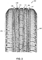
- Figures 1 and 2 generally illustrate a tire or pneumatic tire 100 that includes a first or outer side 102 and a second or inner side 104 that extend between a tread surface 106.
- a tire tread 110 Disposed between the first and second sides 102, 104 is a tire tread 110.
- the tread 110 is formed in a desired pattern and the pattern or tire tread design may differ depending on various needs and end uses as will be appreciated by one skilled in the art. Therefore, many of the illustrated features of the tread 110 will not be described since they form no part of the present disclosure, and instead the description will focus on those features associated with this disclosure.
- first and second outer circumferential grooves 114 further separate the tread 110 into groups of tread block portions, although a greater or lesser number of grooves and tread block portions is also contemplated.
- each of the grooves is defined by first and second sidewalls 116, 118 disposed in facing relation and separated by a groove bottom wall or surface 120.
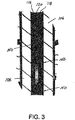
- At least one of the circumferential grooves 112, 114, and preferably the first and second outer grooves114 as shown in the illustrated embodiment, include pockets 130 provided in the sidewalls 116, 118 of the grooves.
- the pockets 130 are circumferentially spaced along the sidewall 116, and likewise are preferably staggered relative to pockets 130 that are circumferentially spaced along the opposite, facing sidewall 118. Stated another way, the pockets in facing sidewalls 116, 118 separated by a bottom surface 120 of the groove are not spaced directly across from one another. Instead, the pockets 130 are staggered so that in a preferred arrangement there is a slight circumferential overlap between the pockets ( Figure 3 ). The degree of staggering or circumferential overlap may vary from one tire to another so that the present disclosure is not limited to a specific amount of overlap.
- one exemplary design for the pocket 130 is a generally trapezoidal recess defined by end walls 132 that angle away from one another as the end walls extend outwardly away from the bottom surface 120 of the groove, i.e., the end walls diverge from one another as the end walls extend radially outward.
- An inner face 134 of the pocket 130 extends upwardly from a bottom surface 136 and the inner face extends at a different angle than an angle of the sidewalls 116, 118 of the circumferential groove.
- the angle of the inner face 134 of the pocket 130 is less than the angle of the sidewall (also referred to as the draft of the groove sidewall) 116 or 118 as measured from a plane perpendicular to the bottom surface 120 of the groove.
- a top of the pocket may or may not coincide with the surface 106 of the tread.
- a series of serrations 150 are provided in each pocket 130.
- the serrations 150 are preferably circumferentially spaced or spaced at a pitch within the pocket 130 between the end walls 132 (and shown here as being evenly spaced from one another between the end walls), extend upwardly from the bottom surface 136, and in this arrangement the serrations terminate at a height below the surface 106 of the tread.
- Each serration 150 is formed by angled walls 152 that converge to form a peak 154, although other cross-sections may be used.
- the illustrated peaks 154 extend from an intersection between the bottom surface 136 of the pocket and intersect with the face 134 of the pocket at a location inwardly of the tread surface 106.
- the serrations 150 do not extend outwardly into the cross-section of the groove where the groove is defined by the sidewalls 116, 118 that diverge outwardly from the bottom surface 120 of the groove.
- the serrations 150 extend outwardly in a generally perpendicular direction from the bottom surface 120 of the groove, and in this instance the serrations also extend in a direction substantially perpendicularly outward from the bottom surface 136 of the pocket 130 ( Figure 6 ).
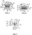
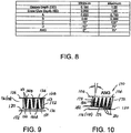
- Figures 7 and 8 provide representative dimensions in connection with the groove, sidewall 116 or 118, pocket 130, and serrations 150. It will be appreciated that these dimensions are exemplary only and not deemed to be limiting.
- the groove depth GD may range from about 0.100" to about 1.00", where the groove depth is measured between the surface 106 of the tire tread and the bottom channel 120.
- a serration depth SD ranges from approximately 0.0502" to approximately 1.00 inches where serration depth is measured from the surface 106 of the tread to the bottom surface 136 of the pocket.
- a pitch A is measured between adjacent peaks of the individual serrations 150. The pitch A may range from a minimum of approximately 0.020" to approximately 0.750".
- Dimension B represents the spacing between surface 106 of the tire tread and the location where the peaks 150 intersect with the face 134, i.e., that dimension that the peaks are spaced from the tread surface 106. This dimension B may range from no spacing (0.00") to approximately 0.900".
- angle C is that angle measured between the peak and a plane extending perpendicularly from the surface 106 of the tread ( Figure 7 ). Oftentimes, this angle will be the same as that associated with the angle of the sidewall when measured relative to a plane extending perpendicularly from the bottom wall 120 of the groove. The angle C ranges from -10° to approximately 120°.
- Angle D is measured between the plane extending perpendicularly from the surface 106 of the tread and face 134 of the pocket 130.
- Figure 9 illustrates a modified arrangement in which some of the serrations 160A intersect with the bottom surface 136 of the pocket 130 and extend upwardly toward the tread surface but terminate below the tread surface 106 while other serrations 160B extend downwardly from the tread surface and terminate prior to reaching the bottom surface 136 of the pocket.
- the serrations 160A, 160B are interleaved with one another to define alternating upwardly and downwardly extending serrations.
- each of the peaks 154 formed by the intersecting walls 152 of the serrations are disposed generally perpendicular to the bottom surface 136 of the pocket, and likewise generally perpendicular to the bottom surface 120 of the groove.
- the serrations 160A, 160B are circumferentially spaced from one another between the end walls 132. Again, however, it is intended that the serrations 160A, 160B do not extend into the cross-sectional area of the groove as defined by sidewalls 116, 118, and bottom wall 120.
- pockets 170 are differently shaped and may include parallel end walls 172 ( Figure 10 ) or the end walls may diverge (see ( Figures 12-13 ) and a bottom wall 176 that is inclined or angled relative to the bottom surface 120 of the groove.
- the serrations 180 extend upwardly from the bottom wall 176 of the pocket 170 and the serrations terminate and intersect with the face 174 of the pocket at a location spaced radially inward from the tread surface 106. Because the peaks 184 of the serrations 180 extend generally perpendicular or normal to the bottom wall 176 of the pocket, the peaks are inclined or angled relative to the bottom surface 120 of the groove.
- the pocket is angled relative to normal as represented by the angle ANG.
- This angle ANG may range from 0° to about 75°.
- the serrations 180 are thus angled relative to the bottom surface 120 of the groove.
- angles of the serrations 180 on the opposing faces 116, 118 of a groove be oriented in opposite directions. Further, because the serrations 180 on the opposing faces 116, 118 are oriented in opposite directions, the height of the serrations are different on the opposing faces in the circumferential direction. That is, the serrations 180 in a given pocket 170 increase in height on one face and decrease in height on the opposite face as one proceeds in a circumferential direction of the groove.
- the serrations 180 provided in pockets 170 of the sidewalls 116, 118 are disposed in a circumferentially staggered, partially overlapping arrangement.
- the recessed pockets (130, 170) with serrations (150, 180) grip into a rib of snow formed in a contact patch of the tire tread.
- the interlocking between the serrations (150, 180) and the rib of snow increases the traction force from snow shear. Lengthening the serrated pockets (130, 170) maximizes the engagement area. Further, orienting the pockets (130, 170) on adjacent, facing groove walls 116, 118 in opposite directions relative to one another enhances the captive engagement of snow in the tread. While larger tread features may provide more interlocking and increased traction with snow shear, a potential trade-off could be hydroplane resistance due to an interrupted water flow through the main circumferential grooves.
- the pockets (130, 170) are recessed into the circumferential groove walls 116, 118 and the serrations (150, 180) do not protrude into the main channel formed by the circumferential grooves. This configuration does not significantly interrupt water flow through the circumferential groove but advantageously still provides interlocking grip features when the groove is filled with snow. Is also believed that the serrations (150, 180) may prevent standing waves forming and reduce generated noise.
- the top of the pocket may or may not coincide with the top edge of the main groove wall.
- the draft angle on a wall that incorporates the pockets/serrations can be different than the draft angle of the main groove.
- the depth or thickness of the serrations would necessarily vary from an increased depth or thickness adjacent the bottom of the pocket, and reduce in depth or thickness adjacent the top of the pocket.
- a preferred form of serrations is defined by a pair of angularly disposed walls or surfaces that intersect to form the peaks. It will be appreciated that the cross-section of the serrations may vary in shape, as well as in depth or thickness as noted above.
- the serrations not protrude from the wall of the pocket or into the groove channel.
- the pocket in the groove sidewall can adopt a wide variety of shapes, and need not be necessarily symmetric or trapezoidal as shown in the illustrated embodiments. It is also envisioned that various combinations of these features may be used, and the present disclosure should not be limited simply to the illustrated combinations of features.
Landscapes
- Engineering & Computer Science (AREA)
- Mechanical Engineering (AREA)
- Tires In General (AREA)
- Structures Of Non-Positive Displacement Pumps (AREA)
Description
- The disclosure relates to an automotive tire, and specifically to a tread thereof. It finds application in a tire that exhibits improved traction, namely engagement of snow in the tread, desired hydroplane performance, handling, and reduced noise generation, and will be described with reference thereto. However, one will appreciate that the exemplary embodiments as shown and described below are amenable to other like applications and that may use one or more of the predicted performance benefits.
- Commonly owned
U.S. Patent No. 6,986,372 -Below discloses a tire in which at least selected grooves have serrated sidewalls. Specifically, all or a major portion of the surface of the sidewalls facing the groove includes the serrations. The serrations terminate short of a groove base or bottom surface. Tires employing these features have met with commercial success. Likewise, commonly ownedU.S. Serial No. 14/049,675, filed 09 October 2013 , discloses a tire tread with angled rib groove walls. PatentUS 2008/0047644 A1 (on which the preamble ofclaim 1 is based) discloses a tire tread arrangement including circumferential grooves in opposing side walls of which radially disposed fine grooves are located. These fine grooves have non-flat portions. In one embodiment the non-flat portion comprises circumferentially disposed ridges connected by flat faces. - There is a continued need for improved performance such as traction, noise, handling, control, braking, etc., and particularly in connection with improved performance in snow without adversely impacting hydroplane resistance.
- A tire with improved performance in snow is disclosed.
- The tire includes first and second laterally spaced sides. A tread is interposed between the first and second sides, and the tread includes a tread surface having at least one groove therein, the at least one groove including facing, first and second sidewalls separated by a groove bottom surface, and a first pocket region of recessed serrations extending over at least a portion of the first sidewall and a second pocket region of recessed serrations extending over at least a portion of the second sidewall, the serrations of the first and second pocket regions being staggered in a circumferential direction relative to one another.
- In an exemplary embodiment, the serrations of the first and second pocket regions partially overlap in the circumferential direction relative to one another.
- In one arrangement, the serrations in the first and second regions extend substantially perpendicular to the groove bottom surface.
- The serrations extend over less than a full height of their associated pocket region, or over substantially a same height as their associated pocket region.
- The serrations are circumferentially spaced from one another in their associated pocket region.
- The serrations extend at an angle between 0 and 180 degrees relative to the groove bottom surface and/or relative to a bottom wall of the associated pocket.
- At least one of the serrations is interleaved with another one of the serrations.
- A cross-section of the serration varies as the serration extends over a height of the pocket region.
- A face of the first pocket region extends at an angle relative to the groove bottom surface that is different than an angle at which the first sidewall extends relative to the groove bottom surface, and preferably at an angle less than that of the first sidewall.
- The serrations in a first pocket region decrease in height in the circumferential direction.
- End walls of the first pocket region are either parallel or non-parallel to one another.
- The sidewalls of the groove are disposed at a non-perpendicular first angle relative to the bottom surface of the groove, and a circumferentially extending face of the pocket region is disposed at a non-perpendicular second angle relative to the bottom surface of the groove where the first angle is greater than the second angle.
- The serrations do not protrude into the groove.
- Serrations on opposite sidewalls of the groove are disposed in opposite directions from one another.
- A height of the first pocket region changes as the first pocket region extends in the circumferential direction, and a height of the serrations changes as the serrations extend in the circumferential direction.
- A primary benefit is improved tire performance, particularly in snow.
- Still another advantage is associated with increased traction force from gripping a rib of snow in the contact patch of the tread.
- Yet another feature is improved interlocking grip features without adversely interrupting water flow through a circumferential groove of the tire.
- Still another benefit is a reduction in standing waves and an associated reduction in noise generation.
- Still other benefits and features of the present disclosure will become apparent upon reading and understanding the following detailed description.
-
-
Figure 1 is a perspective view of a tire includes one or more grooves that include pockets having serrations therein. -
Figure 2 is an enlarged front plan view of a portion of the tire ofFigure 1 . -
Figure 3 is an enlarged plan view of one of the tire grooves shown inFigures 1 and2 . -
Figure 4 is a perspective view of the tire groove ofFigure 3 , showing a pattern of serrations not falling within the scope of the invention. -
Figure 5 is an enlarged view of the pocket and serrations in a groove sidewall not falling within the scope of the invention. -
Figure 6 is a plan view of the pocket and serrations in the groove sidewall not falling within the scope of the invention. -
Figure 7 is a cross-sectional view through a pocket of the groove sidewall. -
Figure 8 is a table of representative dimensional values associated with the features shown inFigure 9 . -
Figure 9 is a plan view similar toFigure 6 of an alternate arrangement of serrations falling within the scope of the invention. -
Figure 10 is a plan view similar toFigures 6 and9 of another arrangement of serrations not falling within the scope of the invention. -
Figure 11 is a plan view of a groove with an alternative arrangement of serrations in pockets of the groove sidewalls not falling within the scope of the invention. -
Figure 12 is a perspective view of one of the sidewalls shown inFigure 11 . -
Figure 13 is an enlarged view of one of the pocket and serrations in the groove sidewall ofFigures 11 -12 . -
Figures 1 and2 generally illustrate a tire orpneumatic tire 100 that includes a first orouter side 102 and a second orinner side 104 that extend between atread surface 106. For ease of illustration and understanding, selected portions of thesides second sides tire tread 110. Thetread 110 is formed in a desired pattern and the pattern or tire tread design may differ depending on various needs and end uses as will be appreciated by one skilled in the art. Therefore, many of the illustrated features of thetread 110 will not be described since they form no part of the present disclosure, and instead the description will focus on those features associated with this disclosure. - More particularly, there are two
central grooves 112 that extend in a circumferential direction around the tire. In addition, first and second outercircumferential grooves 114 further separate thetread 110 into groups of tread block portions, although a greater or lesser number of grooves and tread block portions is also contemplated. As more particularly illustrated inFigures 3 and4 , each of the grooves is defined by first andsecond sidewalls surface 120. At least one of thecircumferential grooves pockets 130 provided in thesidewalls pockets 130 are circumferentially spaced along thesidewall 116, and likewise are preferably staggered relative topockets 130 that are circumferentially spaced along the opposite, facingsidewall 118. Stated another way, the pockets in facingsidewalls bottom surface 120 of the groove are not spaced directly across from one another. Instead, thepockets 130 are staggered so that in a preferred arrangement there is a slight circumferential overlap between the pockets (Figure 3 ). The degree of staggering or circumferential overlap may vary from one tire to another so that the present disclosure is not limited to a specific amount of overlap. - With continued reference to
Figures 1 - 4 , and additional reference toFigures 5-6 , one exemplary design for thepocket 130 is a generally trapezoidal recess defined byend walls 132 that angle away from one another as the end walls extend outwardly away from thebottom surface 120 of the groove, i.e., the end walls diverge from one another as the end walls extend radially outward. Aninner face 134 of thepocket 130 extends upwardly from abottom surface 136 and the inner face extends at a different angle than an angle of thesidewalls Figure 4 , the angle of theinner face 134 of thepocket 130 is less than the angle of the sidewall (also referred to as the draft of the groove sidewall) 116 or 118 as measured from a plane perpendicular to thebottom surface 120 of the groove. A top of the pocket may or may not coincide with thesurface 106 of the tread. - A series of
serrations 150 are provided in eachpocket 130. Theserrations 150 are preferably circumferentially spaced or spaced at a pitch within thepocket 130 between the end walls 132 (and shown here as being evenly spaced from one another between the end walls), extend upwardly from thebottom surface 136, and in this arrangement the serrations terminate at a height below thesurface 106 of the tread. Eachserration 150 is formed byangled walls 152 that converge to form apeak 154, although other cross-sections may be used. The illustrated peaks 154 extend from an intersection between thebottom surface 136 of the pocket and intersect with theface 134 of the pocket at a location inwardly of thetread surface 106. In this manner, theserrations 150 do not extend outwardly into the cross-section of the groove where the groove is defined by thesidewalls bottom surface 120 of the groove. As is also evident inFigures 1-4 , and more particularly inFigures 5-6 , theserrations 150 extend outwardly in a generally perpendicular direction from thebottom surface 120 of the groove, and in this instance the serrations also extend in a direction substantially perpendicularly outward from thebottom surface 136 of the pocket 130 (Figure 6 ). -
Figures 7 and8 provide representative dimensions in connection with the groove,sidewall pocket 130, andserrations 150. It will be appreciated that these dimensions are exemplary only and not deemed to be limiting. As illustrated, the groove depth GD may range from about 0.100" to about 1.00", where the groove depth is measured between thesurface 106 of the tire tread and thebottom channel 120. A serration depth SD ranges from approximately 0.0502" to approximately 1.00 inches where serration depth is measured from thesurface 106 of the tread to thebottom surface 136 of the pocket. A pitch A is measured between adjacent peaks of theindividual serrations 150. The pitch A may range from a minimum of approximately 0.020" to approximately 0.750". Dimension B represents the spacing betweensurface 106 of the tire tread and the location where thepeaks 150 intersect with theface 134, i.e., that dimension that the peaks are spaced from thetread surface 106. This dimension B may range from no spacing (0.00") to approximately 0.900". In addition, angle C is that angle measured between the peak and a plane extending perpendicularly from thesurface 106 of the tread (Figure 7 ). Oftentimes, this angle will be the same as that associated with the angle of the sidewall when measured relative to a plane extending perpendicularly from thebottom wall 120 of the groove. The angle C ranges from -10° to approximately 120°. Angle D is measured between the plane extending perpendicularly from thesurface 106 of the tread and face 134 of thepocket 130. -
Figure 9 illustrates a modified arrangement in which some of theserrations 160A intersect with thebottom surface 136 of thepocket 130 and extend upwardly toward the tread surface but terminate below thetread surface 106 whileother serrations 160B extend downwardly from the tread surface and terminate prior to reaching thebottom surface 136 of the pocket. Further, theserrations peaks 154 formed by the intersectingwalls 152 of the serrations are disposed generally perpendicular to thebottom surface 136 of the pocket, and likewise generally perpendicular to thebottom surface 120 of the groove. Further, theserrations end walls 132. Again, however, it is intended that theserrations bottom wall 120. - Yet another modification is shown in
Figures 10-13 . Here, pockets 170 are differently shaped and may include parallel end walls 172 (Figure 10 ) or the end walls may diverge (see (Figures 12-13 ) and abottom wall 176 that is inclined or angled relative to thebottom surface 120 of the groove. As evident inFigure 10 , theserrations 180 extend upwardly from thebottom wall 176 of thepocket 170 and the serrations terminate and intersect with theface 174 of the pocket at a location spaced radially inward from thetread surface 106. Because thepeaks 184 of theserrations 180 extend generally perpendicular or normal to thebottom wall 176 of the pocket, the peaks are inclined or angled relative to thebottom surface 120 of the groove. In the embodiment ofFigure 10 , the pocket is angled relative to normal as represented by the angle ANG. This angle ANG may range from 0° to about 75°. As best illustrated inFigure 13 , theserrations 180 are thus angled relative to thebottom surface 120 of the groove. - It is preferred that the angles of the
serrations 180 on the opposing faces 116, 118 of a groove be oriented in opposite directions. Further, because theserrations 180 on the opposing faces 116, 118 are oriented in opposite directions, the height of the serrations are different on the opposing faces in the circumferential direction. That is, theserrations 180 in a givenpocket 170 increase in height on one face and decrease in height on the opposite face as one proceeds in a circumferential direction of the groove. Once again, and as perhaps most evident inFigure 11 , theserrations 180 provided inpockets 170 of thesidewalls - The recessed pockets (130, 170) with serrations (150, 180) grip into a rib of snow formed in a contact patch of the tire tread. The interlocking between the serrations (150, 180) and the rib of snow increases the traction force from snow shear. Lengthening the serrated pockets (130, 170) maximizes the engagement area. Further, orienting the pockets (130, 170) on adjacent, facing
groove walls circumferential groove walls - A number of modifications will be readily apparent to one skilled in the art. For example, the top of the pocket may or may not coincide with the top edge of the main groove wall. Likewise, the draft angle on a wall that incorporates the pockets/serrations can be different than the draft angle of the main groove. The depth or thickness of the serrations would necessarily vary from an increased depth or thickness adjacent the bottom of the pocket, and reduce in depth or thickness adjacent the top of the pocket. Further, a preferred form of serrations is defined by a pair of angularly disposed walls or surfaces that intersect to form the peaks. It will be appreciated that the cross-section of the serrations may vary in shape, as well as in depth or thickness as noted above. However, it is preferred that the serrations not protrude from the wall of the pocket or into the groove channel. As also briefly noted above, the pocket in the groove sidewall can adopt a wide variety of shapes, and need not be necessarily symmetric or trapezoidal as shown in the illustrated embodiments. It is also envisioned that various combinations of these features may be used, and the present disclosure should not be limited simply to the illustrated combinations of features.
- This written description uses examples to describe the disclosure, including the best mode, and also to enable any person skilled in the art to make and use the disclosure. The patentable scope of the disclosure is defined by the claims, and may include other examples that occur to those skilled in the art.
Claims (15)
- A tire (100) comprising:first and second laterally spaced sides (102, 104); anda tread interposed between the first and second sides (102, 104), the tread including a tread surface (106) having at least one groove (114) therein, the at least one groove (114) including facing, first and second sidewalls (116, 118) separated by a groove bottom surface (120), and a first pocket region (130) of recessed serrations (160A, 160B) extending over at least a portion of the first sidewall (116) and a second pocket region (130) of recessed serrations (160A, 160B) extending over at least a portion of the second sidewall (118), the serrations (160A, 160B) of the first and second pocket regions (130) being staggered in a circumferential direction relative to one another,characterised in that at least one of the serrations (160A, 160B) is interleaved with another one of the serrations (160A, 160B) in the first pocket region (130) to define alternating upwardly and downwardly extending serrations (160A, 160B).
- The tire (100) of claim 1 wherein the serrations (160A, 160B) of the first and second pocket regions (130) partially overlap in the circumferential direction relative to one another.
- The tire (100) of claim 1 wherein peaks (154) of the serrations (160A, 160B) in the first and second pocket regions (130) extend substantially perpendicular to the groove bottom surface (136).
- The tire (100) of claim 1 wherein the serrations (160A, 160B) extend over less than a full height of their associated pocket region (130).
- The tire (100) of claim 1 wherein the serrations (160A, 160B) extend over substantially a same height as their associated pocket region (130).
- The tire (100) of claim 1 wherein the serrations (160A, 160B) are circumferentially spaced from one another in their associated pocket region (130).
- The tire (100) of claim 1 wherein a cross-section of the serration (160A, 160B) varies as the serration(160A, 160B) extends over a height of the first pocket region (130).
- The tire (100) of claim 1 wherein the serrations (160A, 160B) in a first pocket region (130) decrease in height in the circumferential direction.
- The tire (100) of claim 1 wherein the serrations (160A, 160B) on opposite sidewalls (116, 118) of the groove (114) are disposed in opposite directions from one another.
- The tire (100) of claim 1 wherein the first and second pocket regions (130) are regularly spaced along a circumferential extent of the groove (114).
- The tire (100) of claim 1 wherein the serrations (160A, 160B) extend outwardly from a circumferentially extending face (134) of the first pocket region (130) but do not extend into a channel of the groove (114) defined by the sidewalls (116, 118).
- The tire (100) of claim 1 wherein a depth of at least some of the serrations (160A, 160B) decreases as the serrations (160A, 160B) extend radially outward.
- The tire (100) of claim 1 wherein a height of the first pocket region (130) changes as the first pocket region (130) extends in the circumferential direction.
- The tire (100) of claim 1 wherein some of the serrations (160A, 160B) intersect with a bottom surface (136) of their associated pocket region (130) but terminate below the tread surface (106) and other of the serrations extend downwardly from the tread surface (106) and terminate prior to reaching the bottom surface (136) of their associated pocket region (130).
- The tire (100) of claim 1 wherein peaks (154) of the serrations (160A, 160B) are angled relative to a normal to the tread surface (106) or groove bottom surface (120).
Priority Applications (1)
| Application Number | Priority Date | Filing Date | Title |
|---|---|---|---|
| RS20210434A RS61710B1 (en) | 2013-11-12 | 2014-11-07 | Tire tread including serrations in recessed pockets of groove sidewall |
Applications Claiming Priority (3)
| Application Number | Priority Date | Filing Date | Title |
|---|---|---|---|
| US201361903152P | 2013-11-12 | 2013-11-12 | |
| PCT/US2014/064543 WO2015073315A2 (en) | 2013-11-12 | 2014-11-07 | Tire tread including serrations in recessed pockets of groove sidewall |
| EP14862848.0A EP3068634B1 (en) | 2013-11-12 | 2014-11-07 | Tire tread including serrations in recessed pockets of groove sidewall |
Related Parent Applications (1)
| Application Number | Title | Priority Date | Filing Date |
|---|---|---|---|
| EP14862848.0A Division EP3068634B1 (en) | 2013-11-12 | 2014-11-07 | Tire tread including serrations in recessed pockets of groove sidewall |
Publications (2)
| Publication Number | Publication Date |
|---|---|
| EP3564049A1 EP3564049A1 (en) | 2019-11-06 |
| EP3564049B1 true EP3564049B1 (en) | 2021-03-24 |
Family
ID=53058241
Family Applications (2)
| Application Number | Title | Priority Date | Filing Date |
|---|---|---|---|
| EP19180406.1A Active EP3564049B1 (en) | 2013-11-12 | 2014-11-07 | Tire tread including serrations in recessed pockets of groove sidewall |
| EP14862848.0A Active EP3068634B1 (en) | 2013-11-12 | 2014-11-07 | Tire tread including serrations in recessed pockets of groove sidewall |
Family Applications After (1)
| Application Number | Title | Priority Date | Filing Date |
|---|---|---|---|
| EP14862848.0A Active EP3068634B1 (en) | 2013-11-12 | 2014-11-07 | Tire tread including serrations in recessed pockets of groove sidewall |
Country Status (11)
| Country | Link |
|---|---|
| US (3) | US10308081B2 (en) |
| EP (2) | EP3564049B1 (en) |
| CN (1) | CN105722696B (en) |
| AU (1) | AU2014349001B2 (en) |
| BR (1) | BR112016010541B1 (en) |
| CA (2) | CA2930202C (en) |
| CL (1) | CL2016001112A1 (en) |
| ES (1) | ES2871804T3 (en) |
| MX (1) | MX2016006230A (en) |
| RS (2) | RS61710B1 (en) |
| WO (1) | WO2015073315A2 (en) |
Families Citing this family (13)
| Publication number | Priority date | Publication date | Assignee | Title |
|---|---|---|---|---|
| US10308081B2 (en) * | 2013-11-12 | 2019-06-04 | Cooper Tire & Rubber Company | Tire tread including serrations in recessed pockets of groove sidewall |
| JP6790664B2 (en) * | 2016-09-26 | 2020-11-25 | 住友ゴム工業株式会社 | tire |
| JP6891556B2 (en) * | 2017-03-14 | 2021-06-18 | 住友ゴム工業株式会社 | tire |
| JP6604390B2 (en) * | 2018-01-16 | 2019-11-13 | 横浜ゴム株式会社 | Pneumatic tire |
| USD859288S1 (en) | 2018-05-07 | 2019-09-10 | Cooper Tire & Rubber Company | Tire tread |
| USD867979S1 (en) | 2018-05-17 | 2019-11-26 | Cooper Tire & Rubber Company | Tire tread |
| USD913207S1 (en) * | 2018-12-21 | 2021-03-16 | Cooper Tire & Rubber Company | Tire tread |
| US11298982B2 (en) | 2019-08-29 | 2022-04-12 | The Goodyear Tire & Rubber Company | Tread for a pneumatic tire |
| USD960820S1 (en) | 2020-04-21 | 2022-08-16 | Cooper Tire & Rubber Company | Tire |
| USD986147S1 (en) | 2021-03-31 | 2023-05-16 | The Goodyear Tire & Rubber Company | Tire |
| USD986153S1 (en) | 2021-03-31 | 2023-05-16 | The Goodyear Tire & Rubber Company | Tire |
| USD997856S1 (en) * | 2021-07-29 | 2023-09-05 | The Goodyear Tire & Rubber Company | Tire |
| JP2023044148A (en) * | 2021-09-17 | 2023-03-30 | 住友ゴム工業株式会社 | tire |
Family Cites Families (21)
| Publication number | Priority date | Publication date | Assignee | Title |
|---|---|---|---|---|
| NL42465C (en) | 1936-01-25 | |||
| AT379990B (en) | 1983-12-23 | 1986-03-25 | Semperit Ag | RUNNING FOR VEHICLE AIR TIRES, ESPECIALLY FOR RADIAL TIRES FOR TRUCKS |
| JPH0253608A (en) | 1988-08-12 | 1990-02-22 | Sumitomo Rubber Ind Ltd | Pneumatic radial tire |
| DE3913199A1 (en) | 1989-04-21 | 1990-10-25 | Sp Reifenwerke Gmbh | RUNNING PROFILE IN VEHICLE TIRES |
| DE4138688C2 (en) | 1991-11-25 | 1995-09-14 | Pirelli Reifenwerke | Tread pattern for a vehicle tire |
| JP3095301B2 (en) * | 1992-11-09 | 2000-10-03 | 東洋ゴム工業株式会社 | Radial tires for heavy loads |
| ES2254289T3 (en) | 2000-07-03 | 2006-06-16 | Societe De Technologie Michelin | TIRE BEARING BAND FOR THE TRANSPORTATION OF HEAVY LOADS. |
| EP1345784B1 (en) | 2000-11-28 | 2012-07-04 | Cooper Tire & Rubber Company | Serrated groove sides in a tire |
| JP3949938B2 (en) * | 2001-11-13 | 2007-07-25 | 住友ゴム工業株式会社 | Pneumatic tire |
| US7497240B2 (en) * | 2001-12-19 | 2009-03-03 | The Goodyear Tire & Rubber Company | Tire including projections having sides of unequal length and an undercut extending beneath the apex |
| JP4522790B2 (en) | 2004-08-31 | 2010-08-11 | 住友ゴム工業株式会社 | Pneumatic tire |
| JP4921889B2 (en) | 2006-08-23 | 2012-04-25 | 住友ゴム工業株式会社 | Pneumatic tire |
| JP5129470B2 (en) * | 2006-08-24 | 2013-01-30 | 住友ゴム工業株式会社 | Pneumatic tire |
| JP5148102B2 (en) | 2006-11-24 | 2013-02-20 | 東洋ゴム工業株式会社 | Pneumatic tire |
| CN101588935B (en) | 2006-11-30 | 2012-12-12 | 倍耐力轮胎股份公司 | Tire tread comprising blocks with stepped sidewalls |
| US20080271827A1 (en) * | 2007-05-03 | 2008-11-06 | Andrew Edward Morrison | Pnuematic tire |
| US20080271826A1 (en) | 2007-05-03 | 2008-11-06 | Paul Bryan Maxwell | Pnuematic tire |
| JP4488083B2 (en) | 2008-04-11 | 2010-06-23 | 横浜ゴム株式会社 | Pneumatic tire |
| JP4471031B1 (en) | 2009-02-16 | 2010-06-02 | 横浜ゴム株式会社 | Pneumatic tire |
| JP5899632B2 (en) | 2011-03-07 | 2016-04-06 | 横浜ゴム株式会社 | Pneumatic tire |
| US10308081B2 (en) * | 2013-11-12 | 2019-06-04 | Cooper Tire & Rubber Company | Tire tread including serrations in recessed pockets of groove sidewall |
-
2014
- 2014-11-07 US US15/035,916 patent/US10308081B2/en active Active
- 2014-11-07 BR BR112016010541-9A patent/BR112016010541B1/en active IP Right Grant
- 2014-11-07 RS RS20210434A patent/RS61710B1/en unknown
- 2014-11-07 RS RSP20191023 patent/RS59277B1/en unknown
- 2014-11-07 CA CA2930202A patent/CA2930202C/en active Active
- 2014-11-07 ES ES19180406T patent/ES2871804T3/en active Active
- 2014-11-07 CN CN201480061827.1A patent/CN105722696B/en active Active
- 2014-11-07 MX MX2016006230A patent/MX2016006230A/en active IP Right Grant
- 2014-11-07 EP EP19180406.1A patent/EP3564049B1/en active Active
- 2014-11-07 AU AU2014349001A patent/AU2014349001B2/en active Active
- 2014-11-07 EP EP14862848.0A patent/EP3068634B1/en active Active
- 2014-11-07 CA CA3205256A patent/CA3205256A1/en active Pending
- 2014-11-07 WO PCT/US2014/064543 patent/WO2015073315A2/en active Application Filing
-
2016
- 2016-05-10 CL CL2016001112A patent/CL2016001112A1/en unknown
-
2019
- 2019-05-14 US US16/411,624 patent/US11267296B2/en active Active
-
2022
- 2022-02-10 US US17/668,829 patent/US20220234394A1/en not_active Abandoned
Non-Patent Citations (1)
| Title |
|---|
| None * |
Also Published As
| Publication number | Publication date |
|---|---|
| US20220234394A1 (en) | 2022-07-28 |
| CN105722696B (en) | 2018-04-20 |
| AU2014349001B2 (en) | 2017-06-22 |
| RS61710B1 (en) | 2021-05-31 |
| CA2930202C (en) | 2023-08-22 |
| US10308081B2 (en) | 2019-06-04 |
| US20160280013A1 (en) | 2016-09-29 |
| WO2015073315A3 (en) | 2015-11-12 |
| US11267296B2 (en) | 2022-03-08 |
| RS59277B1 (en) | 2019-10-31 |
| CN105722696A (en) | 2016-06-29 |
| US20190263189A1 (en) | 2019-08-29 |
| CA2930202A1 (en) | 2015-05-21 |
| CL2016001112A1 (en) | 2016-11-11 |
| EP3068634B1 (en) | 2019-06-19 |
| EP3564049A1 (en) | 2019-11-06 |
| WO2015073315A2 (en) | 2015-05-21 |
| EP3068634A4 (en) | 2017-06-21 |
| EP3068634A2 (en) | 2016-09-21 |
| MX2016006230A (en) | 2016-09-07 |
| AU2014349001A1 (en) | 2016-06-02 |
| BR112016010541B1 (en) | 2021-03-09 |
| ES2871804T3 (en) | 2021-11-02 |
| CA3205256A1 (en) | 2015-05-21 |
| NZ719963A (en) | 2021-03-26 |
Similar Documents
| Publication | Publication Date | Title |
|---|---|---|
| EP3564049B1 (en) | Tire tread including serrations in recessed pockets of groove sidewall | |
| US8689843B2 (en) | Snow performance peaks | |
| JP5922364B2 (en) | Reinforced tire tread | |
| US20140360641A1 (en) | Tire tread with angled rib groove walls | |
| EP2860048B1 (en) | Tire tread with angled and serrated groove walls | |
| EP2570272A1 (en) | Tire tread | |
| JP5840489B2 (en) | Pneumatic tire | |
| CA2927941C (en) | Snow tire with directional paddles | |
| JP6527758B2 (en) | Pneumatic tire | |
| EP2465709B1 (en) | Vehicle tire and tire tread band | |
| EP1964692B1 (en) | Pneumatic tire | |
| NZ719963B2 (en) | Tire tread including serrations in recessed pockets of groove sidewall | |
| JP7377091B2 (en) | pneumatic tires | |
| CN111055637A (en) | Snow tire pattern |
Legal Events
| Date | Code | Title | Description |
|---|---|---|---|
| PUAI | Public reference made under article 153(3) epc to a published international application that has entered the european phase |
Free format text: ORIGINAL CODE: 0009012 |
|
| STAA | Information on the status of an ep patent application or granted ep patent |
Free format text: STATUS: THE APPLICATION HAS BEEN PUBLISHED |
|
| AC | Divisional application: reference to earlier application |
Ref document number: 3068634 Country of ref document: EP Kind code of ref document: P |
|
| AK | Designated contracting states |
Kind code of ref document: A1 Designated state(s): AL AT BE BG CH CY CZ DE DK EE ES FI FR GB GR HR HU IE IS IT LI LT LU LV MC MK MT NL NO PL PT RO RS SE SI SK SM TR |
|
| RIN1 | Information on inventor provided before grant (corrected) |
Inventor name: JACOBS, JEREMY J. Inventor name: BONIFAS, PATRICK J. |
|
| STAA | Information on the status of an ep patent application or granted ep patent |
Free format text: STATUS: REQUEST FOR EXAMINATION WAS MADE |
|
| 17P | Request for examination filed |
Effective date: 20200601 |
|
| RBV | Designated contracting states (corrected) |
Designated state(s): AL AT BE BG CH CY CZ DE DK EE ES FI FR GB GR HR HU IE IS IT LI LT LU LV MC MK MT NL NO PL PT RO RS SE SI SK SM TR |
|
| GRAP | Despatch of communication of intention to grant a patent |
Free format text: ORIGINAL CODE: EPIDOSNIGR1 |
|
| STAA | Information on the status of an ep patent application or granted ep patent |
Free format text: STATUS: GRANT OF PATENT IS INTENDED |
|
| RIC1 | Information provided on ipc code assigned before grant |
Ipc: B60C 11/12 20060101ALN20200924BHEP Ipc: B60C 11/13 20060101AFI20200924BHEP Ipc: B60C 11/03 20060101ALI20200924BHEP |
|
| INTG | Intention to grant announced |
Effective date: 20201014 |
|
| GRAS | Grant fee paid |
Free format text: ORIGINAL CODE: EPIDOSNIGR3 |
|
| GRAA | (expected) grant |
Free format text: ORIGINAL CODE: 0009210 |
|
| STAA | Information on the status of an ep patent application or granted ep patent |
Free format text: STATUS: THE PATENT HAS BEEN GRANTED |
|
| AC | Divisional application: reference to earlier application |
Ref document number: 3068634 Country of ref document: EP Kind code of ref document: P |
|
| AK | Designated contracting states |
Kind code of ref document: B1 Designated state(s): AL AT BE BG CH CY CZ DE DK EE ES FI FR GB GR HR HU IE IS IT LI LT LU LV MC MK MT NL NO PL PT RO RS SE SI SK SM TR |
|
| REG | Reference to a national code |
Ref country code: GB Ref legal event code: FG4D |
|
| REG | Reference to a national code |
Ref country code: CH Ref legal event code: EP |
|
| REG | Reference to a national code |
Ref country code: DE Ref legal event code: R096 Ref document number: 602014076082 Country of ref document: DE |
|
| REG | Reference to a national code |
Ref country code: IE Ref legal event code: FG4D |
|
| REG | Reference to a national code |
Ref country code: AT Ref legal event code: REF Ref document number: 1374117 Country of ref document: AT Kind code of ref document: T Effective date: 20210415 |
|
| REG | Reference to a national code |
Ref country code: LT Ref legal event code: MG9D |
|
| PG25 | Lapsed in a contracting state [announced via postgrant information from national office to epo] |
Ref country code: NO Free format text: LAPSE BECAUSE OF FAILURE TO SUBMIT A TRANSLATION OF THE DESCRIPTION OR TO PAY THE FEE WITHIN THE PRESCRIBED TIME-LIMIT Effective date: 20210624 Ref country code: GR Free format text: LAPSE BECAUSE OF FAILURE TO SUBMIT A TRANSLATION OF THE DESCRIPTION OR TO PAY THE FEE WITHIN THE PRESCRIBED TIME-LIMIT Effective date: 20210625 Ref country code: FI Free format text: LAPSE BECAUSE OF FAILURE TO SUBMIT A TRANSLATION OF THE DESCRIPTION OR TO PAY THE FEE WITHIN THE PRESCRIBED TIME-LIMIT Effective date: 20210324 Ref country code: HR Free format text: LAPSE BECAUSE OF FAILURE TO SUBMIT A TRANSLATION OF THE DESCRIPTION OR TO PAY THE FEE WITHIN THE PRESCRIBED TIME-LIMIT Effective date: 20210324 Ref country code: BG Free format text: LAPSE BECAUSE OF FAILURE TO SUBMIT A TRANSLATION OF THE DESCRIPTION OR TO PAY THE FEE WITHIN THE PRESCRIBED TIME-LIMIT Effective date: 20210624 |
|
| PG25 | Lapsed in a contracting state [announced via postgrant information from national office to epo] |
Ref country code: SE Free format text: LAPSE BECAUSE OF FAILURE TO SUBMIT A TRANSLATION OF THE DESCRIPTION OR TO PAY THE FEE WITHIN THE PRESCRIBED TIME-LIMIT Effective date: 20210324 Ref country code: LV Free format text: LAPSE BECAUSE OF FAILURE TO SUBMIT A TRANSLATION OF THE DESCRIPTION OR TO PAY THE FEE WITHIN THE PRESCRIBED TIME-LIMIT Effective date: 20210324 |
|
| REG | Reference to a national code |
Ref country code: NL Ref legal event code: MP Effective date: 20210324 |
|
| REG | Reference to a national code |
Ref country code: AT Ref legal event code: MK05 Ref document number: 1374117 Country of ref document: AT Kind code of ref document: T Effective date: 20210324 |
|
| PG25 | Lapsed in a contracting state [announced via postgrant information from national office to epo] |
Ref country code: NL Free format text: LAPSE BECAUSE OF FAILURE TO SUBMIT A TRANSLATION OF THE DESCRIPTION OR TO PAY THE FEE WITHIN THE PRESCRIBED TIME-LIMIT Effective date: 20210324 |
|
| PG25 | Lapsed in a contracting state [announced via postgrant information from national office to epo] |
Ref country code: SM Free format text: LAPSE BECAUSE OF FAILURE TO SUBMIT A TRANSLATION OF THE DESCRIPTION OR TO PAY THE FEE WITHIN THE PRESCRIBED TIME-LIMIT Effective date: 20210324 Ref country code: AT Free format text: LAPSE BECAUSE OF FAILURE TO SUBMIT A TRANSLATION OF THE DESCRIPTION OR TO PAY THE FEE WITHIN THE PRESCRIBED TIME-LIMIT Effective date: 20210324 Ref country code: CZ Free format text: LAPSE BECAUSE OF FAILURE TO SUBMIT A TRANSLATION OF THE DESCRIPTION OR TO PAY THE FEE WITHIN THE PRESCRIBED TIME-LIMIT Effective date: 20210324 Ref country code: EE Free format text: LAPSE BECAUSE OF FAILURE TO SUBMIT A TRANSLATION OF THE DESCRIPTION OR TO PAY THE FEE WITHIN THE PRESCRIBED TIME-LIMIT Effective date: 20210324 Ref country code: LT Free format text: LAPSE BECAUSE OF FAILURE TO SUBMIT A TRANSLATION OF THE DESCRIPTION OR TO PAY THE FEE WITHIN THE PRESCRIBED TIME-LIMIT Effective date: 20210324 |
|
| REG | Reference to a national code |
Ref country code: ES Ref legal event code: FG2A Ref document number: 2871804 Country of ref document: ES Kind code of ref document: T3 Effective date: 20211102 |
|
| PG25 | Lapsed in a contracting state [announced via postgrant information from national office to epo] |
Ref country code: IS Free format text: LAPSE BECAUSE OF FAILURE TO SUBMIT A TRANSLATION OF THE DESCRIPTION OR TO PAY THE FEE WITHIN THE PRESCRIBED TIME-LIMIT Effective date: 20210724 Ref country code: PL Free format text: LAPSE BECAUSE OF FAILURE TO SUBMIT A TRANSLATION OF THE DESCRIPTION OR TO PAY THE FEE WITHIN THE PRESCRIBED TIME-LIMIT Effective date: 20210324 Ref country code: SK Free format text: LAPSE BECAUSE OF FAILURE TO SUBMIT A TRANSLATION OF THE DESCRIPTION OR TO PAY THE FEE WITHIN THE PRESCRIBED TIME-LIMIT Effective date: 20210324 Ref country code: PT Free format text: LAPSE BECAUSE OF FAILURE TO SUBMIT A TRANSLATION OF THE DESCRIPTION OR TO PAY THE FEE WITHIN THE PRESCRIBED TIME-LIMIT Effective date: 20210726 Ref country code: RO Free format text: LAPSE BECAUSE OF FAILURE TO SUBMIT A TRANSLATION OF THE DESCRIPTION OR TO PAY THE FEE WITHIN THE PRESCRIBED TIME-LIMIT Effective date: 20210324 |
|
| REG | Reference to a national code |
Ref country code: DE Ref legal event code: R097 Ref document number: 602014076082 Country of ref document: DE |
|
| PG25 | Lapsed in a contracting state [announced via postgrant information from national office to epo] |
Ref country code: DK Free format text: LAPSE BECAUSE OF FAILURE TO SUBMIT A TRANSLATION OF THE DESCRIPTION OR TO PAY THE FEE WITHIN THE PRESCRIBED TIME-LIMIT Effective date: 20210324 Ref country code: AL Free format text: LAPSE BECAUSE OF FAILURE TO SUBMIT A TRANSLATION OF THE DESCRIPTION OR TO PAY THE FEE WITHIN THE PRESCRIBED TIME-LIMIT Effective date: 20210324 |
|
| PLBE | No opposition filed within time limit |
Free format text: ORIGINAL CODE: 0009261 |
|
| STAA | Information on the status of an ep patent application or granted ep patent |
Free format text: STATUS: NO OPPOSITION FILED WITHIN TIME LIMIT |
|
| PG25 | Lapsed in a contracting state [announced via postgrant information from national office to epo] |
Ref country code: SI Free format text: LAPSE BECAUSE OF FAILURE TO SUBMIT A TRANSLATION OF THE DESCRIPTION OR TO PAY THE FEE WITHIN THE PRESCRIBED TIME-LIMIT Effective date: 20210324 |
|
| 26N | No opposition filed |
Effective date: 20220104 |
|
| PG25 | Lapsed in a contracting state [announced via postgrant information from national office to epo] |
Ref country code: IS Free format text: LAPSE BECAUSE OF FAILURE TO SUBMIT A TRANSLATION OF THE DESCRIPTION OR TO PAY THE FEE WITHIN THE PRESCRIBED TIME-LIMIT Effective date: 20210724 |
|
| PG25 | Lapsed in a contracting state [announced via postgrant information from national office to epo] |
Ref country code: MC Free format text: LAPSE BECAUSE OF FAILURE TO SUBMIT A TRANSLATION OF THE DESCRIPTION OR TO PAY THE FEE WITHIN THE PRESCRIBED TIME-LIMIT Effective date: 20210324 |
|
| REG | Reference to a national code |
Ref country code: CH Ref legal event code: PL |
|
| PG25 | Lapsed in a contracting state [announced via postgrant information from national office to epo] |
Ref country code: LU Free format text: LAPSE BECAUSE OF NON-PAYMENT OF DUE FEES Effective date: 20211107 Ref country code: BE Free format text: LAPSE BECAUSE OF NON-PAYMENT OF DUE FEES Effective date: 20211130 |
|
| REG | Reference to a national code |
Ref country code: BE Ref legal event code: MM Effective date: 20211130 |
|
| PG25 | Lapsed in a contracting state [announced via postgrant information from national office to epo] |
Ref country code: LI Free format text: LAPSE BECAUSE OF NON-PAYMENT OF DUE FEES Effective date: 20211130 Ref country code: CH Free format text: LAPSE BECAUSE OF NON-PAYMENT OF DUE FEES Effective date: 20211130 |
|
| PG25 | Lapsed in a contracting state [announced via postgrant information from national office to epo] |
Ref country code: IE Free format text: LAPSE BECAUSE OF NON-PAYMENT OF DUE FEES Effective date: 20211107 |
|
| REG | Reference to a national code |
Ref country code: ES Ref legal event code: PC2A Owner name: THE GOODYEAR TIRE & RUBBER COMPANY Effective date: 20230227 |
|
| REG | Reference to a national code |
Ref country code: DE Ref legal event code: R082 Ref document number: 602014076082 Country of ref document: DE Representative=s name: KUTSCH, BERND, DIPL.-PHYS., DE Ref country code: DE Ref legal event code: R082 Ref document number: 602014076082 Country of ref document: DE |
|
| REG | Reference to a national code |
Ref country code: GB Ref legal event code: 732E Free format text: REGISTERED BETWEEN 20230323 AND 20230329 |
|
| REG | Reference to a national code |
Ref country code: DE Ref legal event code: R082 Ref document number: 602014076082 Country of ref document: DE Representative=s name: KUTSCH, BERND, DIPL.-PHYS., DE |
|
| REG | Reference to a national code |
Ref country code: DE Ref legal event code: R081 Ref document number: 602014076082 Country of ref document: DE Owner name: THE GOODYEAR TIRE & RUBBER COMPANY, AKRON, US Free format text: FORMER OWNER: COOPER TIRE & RUBBER COMPANY, FINDLAY, OH, US |
|
| PG25 | Lapsed in a contracting state [announced via postgrant information from national office to epo] |
Ref country code: CY Free format text: LAPSE BECAUSE OF FAILURE TO SUBMIT A TRANSLATION OF THE DESCRIPTION OR TO PAY THE FEE WITHIN THE PRESCRIBED TIME-LIMIT Effective date: 20210324 |
|
| PG25 | Lapsed in a contracting state [announced via postgrant information from national office to epo] |
Ref country code: HU Free format text: LAPSE BECAUSE OF FAILURE TO SUBMIT A TRANSLATION OF THE DESCRIPTION OR TO PAY THE FEE WITHIN THE PRESCRIBED TIME-LIMIT; INVALID AB INITIO Effective date: 20141107 |
|
| PGFP | Annual fee paid to national office [announced via postgrant information from national office to epo] |
Ref country code: GB Payment date: 20230914 Year of fee payment: 10 |
|
| PGFP | Annual fee paid to national office [announced via postgrant information from national office to epo] |
Ref country code: FR Payment date: 20230911 Year of fee payment: 10 |
|
| PGFP | Annual fee paid to national office [announced via postgrant information from national office to epo] |
Ref country code: ES Payment date: 20231208 Year of fee payment: 10 |
|
| PGFP | Annual fee paid to national office [announced via postgrant information from national office to epo] |
Ref country code: RS Payment date: 20231020 Year of fee payment: 10 Ref country code: IT Payment date: 20231010 Year of fee payment: 10 Ref country code: DE Payment date: 20230912 Year of fee payment: 10 |
|
| PG25 | Lapsed in a contracting state [announced via postgrant information from national office to epo] |
Ref country code: MK Free format text: LAPSE BECAUSE OF FAILURE TO SUBMIT A TRANSLATION OF THE DESCRIPTION OR TO PAY THE FEE WITHIN THE PRESCRIBED TIME-LIMIT Effective date: 20210324 |