EP3564028A1 - Dissimilar metal joined material and method of manufacturing same - Google Patents
Dissimilar metal joined material and method of manufacturing same Download PDFInfo
- Publication number
- EP3564028A1 EP3564028A1 EP19169284.7A EP19169284A EP3564028A1 EP 3564028 A1 EP3564028 A1 EP 3564028A1 EP 19169284 A EP19169284 A EP 19169284A EP 3564028 A1 EP3564028 A1 EP 3564028A1
- Authority
- EP
- European Patent Office
- Prior art keywords
- thermal expansion
- layer
- corrosion resistant
- plating layer
- expansion layer
- Prior art date
- Legal status (The legal status is an assumption and is not a legal conclusion. Google has not performed a legal analysis and makes no representation as to the accuracy of the status listed.)
- Granted
Links
Images

Classifications
-
- B—PERFORMING OPERATIONS; TRANSPORTING
- B23—MACHINE TOOLS; METAL-WORKING NOT OTHERWISE PROVIDED FOR
- B23K—SOLDERING OR UNSOLDERING; WELDING; CLADDING OR PLATING BY SOLDERING OR WELDING; CUTTING BY APPLYING HEAT LOCALLY, e.g. FLAME CUTTING; WORKING BY LASER BEAM
- B23K20/00—Non-electric welding by applying impact or other pressure, with or without the application of heat, e.g. cladding or plating
- B23K20/04—Non-electric welding by applying impact or other pressure, with or without the application of heat, e.g. cladding or plating by means of a rolling mill
-
- B—PERFORMING OPERATIONS; TRANSPORTING
- B23—MACHINE TOOLS; METAL-WORKING NOT OTHERWISE PROVIDED FOR
- B23K—SOLDERING OR UNSOLDERING; WELDING; CLADDING OR PLATING BY SOLDERING OR WELDING; CUTTING BY APPLYING HEAT LOCALLY, e.g. FLAME CUTTING; WORKING BY LASER BEAM
- B23K26/00—Working by laser beam, e.g. welding, cutting or boring
- B23K26/20—Bonding
- B23K26/32—Bonding taking account of the properties of the material involved
- B23K26/323—Bonding taking account of the properties of the material involved involving parts made of dissimilar metallic material
-
- B—PERFORMING OPERATIONS; TRANSPORTING
- B32—LAYERED PRODUCTS
- B32B—LAYERED PRODUCTS, i.e. PRODUCTS BUILT-UP OF STRATA OF FLAT OR NON-FLAT, e.g. CELLULAR OR HONEYCOMB, FORM
- B32B15/00—Layered products comprising a layer of metal
- B32B15/01—Layered products comprising a layer of metal all layers being exclusively metallic
-
- C—CHEMISTRY; METALLURGY
- C23—COATING METALLIC MATERIAL; COATING MATERIAL WITH METALLIC MATERIAL; CHEMICAL SURFACE TREATMENT; DIFFUSION TREATMENT OF METALLIC MATERIAL; COATING BY VACUUM EVAPORATION, BY SPUTTERING, BY ION IMPLANTATION OR BY CHEMICAL VAPOUR DEPOSITION, IN GENERAL; INHIBITING CORROSION OF METALLIC MATERIAL OR INCRUSTATION IN GENERAL
- C23C—COATING METALLIC MATERIAL; COATING MATERIAL WITH METALLIC MATERIAL; SURFACE TREATMENT OF METALLIC MATERIAL BY DIFFUSION INTO THE SURFACE, BY CHEMICAL CONVERSION OR SUBSTITUTION; COATING BY VACUUM EVAPORATION, BY SPUTTERING, BY ION IMPLANTATION OR BY CHEMICAL VAPOUR DEPOSITION, IN GENERAL
- C23C18/00—Chemical coating by decomposition of either liquid compounds or solutions of the coating forming compounds, without leaving reaction products of surface material in the coating; Contact plating
- C23C18/16—Chemical coating by decomposition of either liquid compounds or solutions of the coating forming compounds, without leaving reaction products of surface material in the coating; Contact plating by reduction or substitution, e.g. electroless plating
- C23C18/1601—Process or apparatus
- C23C18/1633—Process of electroless plating
- C23C18/1635—Composition of the substrate
- C23C18/1637—Composition of the substrate metallic substrate
-
- C—CHEMISTRY; METALLURGY
- C23—COATING METALLIC MATERIAL; COATING MATERIAL WITH METALLIC MATERIAL; CHEMICAL SURFACE TREATMENT; DIFFUSION TREATMENT OF METALLIC MATERIAL; COATING BY VACUUM EVAPORATION, BY SPUTTERING, BY ION IMPLANTATION OR BY CHEMICAL VAPOUR DEPOSITION, IN GENERAL; INHIBITING CORROSION OF METALLIC MATERIAL OR INCRUSTATION IN GENERAL
- C23C—COATING METALLIC MATERIAL; COATING MATERIAL WITH METALLIC MATERIAL; SURFACE TREATMENT OF METALLIC MATERIAL BY DIFFUSION INTO THE SURFACE, BY CHEMICAL CONVERSION OR SUBSTITUTION; COATING BY VACUUM EVAPORATION, BY SPUTTERING, BY ION IMPLANTATION OR BY CHEMICAL VAPOUR DEPOSITION, IN GENERAL
- C23C18/00—Chemical coating by decomposition of either liquid compounds or solutions of the coating forming compounds, without leaving reaction products of surface material in the coating; Contact plating
- C23C18/16—Chemical coating by decomposition of either liquid compounds or solutions of the coating forming compounds, without leaving reaction products of surface material in the coating; Contact plating by reduction or substitution, e.g. electroless plating
- C23C18/1601—Process or apparatus
- C23C18/1633—Process of electroless plating
- C23C18/1646—Characteristics of the product obtained
- C23C18/165—Multilayered product
-
- C—CHEMISTRY; METALLURGY
- C23—COATING METALLIC MATERIAL; COATING MATERIAL WITH METALLIC MATERIAL; CHEMICAL SURFACE TREATMENT; DIFFUSION TREATMENT OF METALLIC MATERIAL; COATING BY VACUUM EVAPORATION, BY SPUTTERING, BY ION IMPLANTATION OR BY CHEMICAL VAPOUR DEPOSITION, IN GENERAL; INHIBITING CORROSION OF METALLIC MATERIAL OR INCRUSTATION IN GENERAL
- C23C—COATING METALLIC MATERIAL; COATING MATERIAL WITH METALLIC MATERIAL; SURFACE TREATMENT OF METALLIC MATERIAL BY DIFFUSION INTO THE SURFACE, BY CHEMICAL CONVERSION OR SUBSTITUTION; COATING BY VACUUM EVAPORATION, BY SPUTTERING, BY ION IMPLANTATION OR BY CHEMICAL VAPOUR DEPOSITION, IN GENERAL
- C23C18/00—Chemical coating by decomposition of either liquid compounds or solutions of the coating forming compounds, without leaving reaction products of surface material in the coating; Contact plating
- C23C18/16—Chemical coating by decomposition of either liquid compounds or solutions of the coating forming compounds, without leaving reaction products of surface material in the coating; Contact plating by reduction or substitution, e.g. electroless plating
- C23C18/18—Pretreatment of the material to be coated
- C23C18/1803—Pretreatment of the material to be coated of metallic material surfaces or of a non-specific material surfaces
- C23C18/1824—Pretreatment of the material to be coated of metallic material surfaces or of a non-specific material surfaces by chemical pretreatment
- C23C18/1837—Multistep pretreatment
-
- C—CHEMISTRY; METALLURGY
- C23—COATING METALLIC MATERIAL; COATING MATERIAL WITH METALLIC MATERIAL; CHEMICAL SURFACE TREATMENT; DIFFUSION TREATMENT OF METALLIC MATERIAL; COATING BY VACUUM EVAPORATION, BY SPUTTERING, BY ION IMPLANTATION OR BY CHEMICAL VAPOUR DEPOSITION, IN GENERAL; INHIBITING CORROSION OF METALLIC MATERIAL OR INCRUSTATION IN GENERAL
- C23C—COATING METALLIC MATERIAL; COATING MATERIAL WITH METALLIC MATERIAL; SURFACE TREATMENT OF METALLIC MATERIAL BY DIFFUSION INTO THE SURFACE, BY CHEMICAL CONVERSION OR SUBSTITUTION; COATING BY VACUUM EVAPORATION, BY SPUTTERING, BY ION IMPLANTATION OR BY CHEMICAL VAPOUR DEPOSITION, IN GENERAL
- C23C18/00—Chemical coating by decomposition of either liquid compounds or solutions of the coating forming compounds, without leaving reaction products of surface material in the coating; Contact plating
- C23C18/16—Chemical coating by decomposition of either liquid compounds or solutions of the coating forming compounds, without leaving reaction products of surface material in the coating; Contact plating by reduction or substitution, e.g. electroless plating
- C23C18/31—Coating with metals
- C23C18/32—Coating with nickel, cobalt or mixtures thereof with phosphorus or boron
-
- C—CHEMISTRY; METALLURGY
- C23—COATING METALLIC MATERIAL; COATING MATERIAL WITH METALLIC MATERIAL; CHEMICAL SURFACE TREATMENT; DIFFUSION TREATMENT OF METALLIC MATERIAL; COATING BY VACUUM EVAPORATION, BY SPUTTERING, BY ION IMPLANTATION OR BY CHEMICAL VAPOUR DEPOSITION, IN GENERAL; INHIBITING CORROSION OF METALLIC MATERIAL OR INCRUSTATION IN GENERAL
- C23C—COATING METALLIC MATERIAL; COATING MATERIAL WITH METALLIC MATERIAL; SURFACE TREATMENT OF METALLIC MATERIAL BY DIFFUSION INTO THE SURFACE, BY CHEMICAL CONVERSION OR SUBSTITUTION; COATING BY VACUUM EVAPORATION, BY SPUTTERING, BY ION IMPLANTATION OR BY CHEMICAL VAPOUR DEPOSITION, IN GENERAL
- C23C18/00—Chemical coating by decomposition of either liquid compounds or solutions of the coating forming compounds, without leaving reaction products of surface material in the coating; Contact plating
- C23C18/16—Chemical coating by decomposition of either liquid compounds or solutions of the coating forming compounds, without leaving reaction products of surface material in the coating; Contact plating by reduction or substitution, e.g. electroless plating
- C23C18/31—Coating with metals
- C23C18/32—Coating with nickel, cobalt or mixtures thereof with phosphorus or boron
- C23C18/34—Coating with nickel, cobalt or mixtures thereof with phosphorus or boron using reducing agents
-
- C—CHEMISTRY; METALLURGY
- C23—COATING METALLIC MATERIAL; COATING MATERIAL WITH METALLIC MATERIAL; CHEMICAL SURFACE TREATMENT; DIFFUSION TREATMENT OF METALLIC MATERIAL; COATING BY VACUUM EVAPORATION, BY SPUTTERING, BY ION IMPLANTATION OR BY CHEMICAL VAPOUR DEPOSITION, IN GENERAL; INHIBITING CORROSION OF METALLIC MATERIAL OR INCRUSTATION IN GENERAL
- C23C—COATING METALLIC MATERIAL; COATING MATERIAL WITH METALLIC MATERIAL; SURFACE TREATMENT OF METALLIC MATERIAL BY DIFFUSION INTO THE SURFACE, BY CHEMICAL CONVERSION OR SUBSTITUTION; COATING BY VACUUM EVAPORATION, BY SPUTTERING, BY ION IMPLANTATION OR BY CHEMICAL VAPOUR DEPOSITION, IN GENERAL
- C23C18/00—Chemical coating by decomposition of either liquid compounds or solutions of the coating forming compounds, without leaving reaction products of surface material in the coating; Contact plating
- C23C18/16—Chemical coating by decomposition of either liquid compounds or solutions of the coating forming compounds, without leaving reaction products of surface material in the coating; Contact plating by reduction or substitution, e.g. electroless plating
- C23C18/48—Coating with alloys
- C23C18/50—Coating with alloys with alloys based on iron, cobalt or nickel
-
- C—CHEMISTRY; METALLURGY
- C25—ELECTROLYTIC OR ELECTROPHORETIC PROCESSES; APPARATUS THEREFOR
- C25D—PROCESSES FOR THE ELECTROLYTIC OR ELECTROPHORETIC PRODUCTION OF COATINGS; ELECTROFORMING; APPARATUS THEREFOR
- C25D3/00—Electroplating: Baths therefor
- C25D3/02—Electroplating: Baths therefor from solutions
- C25D3/12—Electroplating: Baths therefor from solutions of nickel or cobalt
-
- C—CHEMISTRY; METALLURGY
- C25—ELECTROLYTIC OR ELECTROPHORETIC PROCESSES; APPARATUS THEREFOR
- C25D—PROCESSES FOR THE ELECTROLYTIC OR ELECTROPHORETIC PRODUCTION OF COATINGS; ELECTROFORMING; APPARATUS THEREFOR
- C25D5/00—Electroplating characterised by the process; Pretreatment or after-treatment of workpieces
- C25D5/34—Pretreatment of metallic surfaces to be electroplated
-
- C—CHEMISTRY; METALLURGY
- C25—ELECTROLYTIC OR ELECTROPHORETIC PROCESSES; APPARATUS THEREFOR
- C25D—PROCESSES FOR THE ELECTROLYTIC OR ELECTROPHORETIC PRODUCTION OF COATINGS; ELECTROFORMING; APPARATUS THEREFOR
- C25D7/00—Electroplating characterised by the article coated
-
- B—PERFORMING OPERATIONS; TRANSPORTING
- B23—MACHINE TOOLS; METAL-WORKING NOT OTHERWISE PROVIDED FOR
- B23K—SOLDERING OR UNSOLDERING; WELDING; CLADDING OR PLATING BY SOLDERING OR WELDING; CUTTING BY APPLYING HEAT LOCALLY, e.g. FLAME CUTTING; WORKING BY LASER BEAM
- B23K2103/00—Materials to be soldered, welded or cut
- B23K2103/18—Dissimilar materials
-
- C—CHEMISTRY; METALLURGY
- C21—METALLURGY OF IRON
- C21D—MODIFYING THE PHYSICAL STRUCTURE OF FERROUS METALS; GENERAL DEVICES FOR HEAT TREATMENT OF FERROUS OR NON-FERROUS METALS OR ALLOYS; MAKING METAL MALLEABLE, e.g. BY DECARBURISATION OR TEMPERING
- C21D2281/00—Making use of special physico-chemical means
- C21D2281/02—Making use of special physico-chemical means temperature gradient
-
- H—ELECTRICITY
- H01—ELECTRIC ELEMENTS
- H01H—ELECTRIC SWITCHES; RELAYS; SELECTORS; EMERGENCY PROTECTIVE DEVICES
- H01H37/00—Thermally-actuated switches
- H01H37/02—Details
- H01H37/32—Thermally-sensitive members
- H01H37/52—Thermally-sensitive members actuated due to deflection of bimetallic element
- H01H2037/525—Details of manufacturing of the bimetals, e.g. connection to non bimetallic elements or insulating coatings
-
- H—ELECTRICITY
- H01—ELECTRIC ELEMENTS
- H01H—ELECTRIC SWITCHES; RELAYS; SELECTORS; EMERGENCY PROTECTIVE DEVICES
- H01H37/00—Thermally-actuated switches
- H01H37/02—Details
- H01H37/32—Thermally-sensitive members
- H01H37/52—Thermally-sensitive members actuated due to deflection of bimetallic element
- H01H2037/526—Materials for bimetals
Definitions
- the present invention relates to a dissimilar metal joined material and a method of manufacturing the same.
- a dissimilar metal joined material such as a bimetal and a trimetal is known.
- the dissimilar metal joined material is formed by overlapping at least two types of metal different from each other.
- a degree of curvature changes with a temperature change. Therefore, the dissimilar metal joined material is used in various fields of consumer use and industrial use such as thermostats and thermal switches which operate with the temperature change.
- JP-B-3-57438 proposes that a passive film is formed on a surface of the dissimilar metal joined material to improve corrosion resistance.
- the passive film proposed in JP-B-3-57438 is a metal oxide film and is hard and brittle.
- a thickness of the passive film formed by the method proposed in JP-B-3-57438 is about 2 to 3 nm. Therefore, the passive film may crack each time the dissimilar metal joined material repeats curving, and it is difficult to maintain the corrosion resistance for a long period. Even if the thickness of the passive film can be increased, the passive film easily cracks further, and it is possible to affect characteristics such as an curvature coefficient and volume resistivity of the dissimilar metal joined material.
- an object of the present invention is to provide a dissimilar metal joined material that has corrosion resistance that can prolong life resulting from corrosion and has a small difference from original characteristics.
- a dissimilar metal joined material including: a clad material including a high thermal expansion layer composed of an alloy containing Mn, and a low thermal expansion layer composed of an alloy containing Ni, the low thermal expansion layer being joined directly to the high thermal expansion layer or via an intermediate layer; and a corrosion resistant plating layer provided on at least a surface of the high thermal expansion layer, the corrosion resistant plating layer having a thickness of 10 nm to 120 nm.
- Another aspect of the present invention provides a method of manufacturing a dissimilar metal joined material, the method includes the successive steps of: degreasing surfaces of a clad material containing a high thermal expansion layer composed of an alloy containing Mn and a low thermal expansion layer composed of an alloy containing Ni, the low thermal expansion layer being joined directly to the high thermal expansion layer or joined via an intermediate layer; washing at least the surface of the high thermal expansion layer; plating at least the surface of the high thermal expansion layer with a plating solution to form a corrosion resistant plating layer having a thickness of 10 nm to 120 nm; removing the plating solution from the surface of the high thermal expansion layer; and drying the dissimilar metal joined material.
- a dissimilar metal joined material that has corrosion resistance capable of prolonging life resulting from corrosion and has a small difference from the original characteristics.
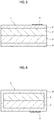
- Fig. 1 is a cross-sectional view of a bimetal 1 (an example of the dissimilar metal joined material) according to the present embodiment.
- the bimetal 1 includes a high thermal expansion layer 2, a low thermal expansion layer 3, and a corrosion resistant plating layer 4.
- the corrosion resistant plating layer 4, the high thermal expansion layer 2, and the low thermal expansion layer 3 are stacked in this order.
- the high thermal expansion layer 2 and the low thermal expansion layer 3 constitute a clad material joined through rolling, diffusion annealing, and the like.
- the present invention can also be applied to a trimetal (an example of the dissimilar metal joined material) constituted by a clad material formed by adding an intermediate layer (not illustrated) between the high thermal expansion layer 2 and the low thermal expansion layer 3 and joined through rolling, diffusion annealing, and the like.
- the clad material without the corrosion resistant plating layer 4 may have a total thickness of 50 ⁇ m to 1 mm. In a case of a relatively thin clad material having a total thickness of 50 ⁇ m to 0.5 mm, it is considered that the corrosion has a large impact, and thus it is particularly effective to form the corrosion resistant plating layer 4 to obtain corrosion resistance.
- the high thermal expansion layer 2 is composed of an alloy (metal) containing Mn (material of the high thermal expansion layer 2 constituting raw material plate). Mn is expected to increase the thermal expansion coefficient. By intentionally adding Mn to the high thermal expansion layer 2, it is configured such that a thermal expansion coefficient of the high thermal expansion layer 2 is larger than that of the low thermal expansion layer 3.
- the high thermal expansion layer 2 may be an Fe-Ni-Mn based alloy containing Mn.
- the high thermal expansion layer 2 may contain 15% to 30% of Ni, preferably 20% to 26% of Ni, and more preferably 22% to 24% of Ni.
- the high thermal expansion layer 2 may contain 2% to 10% of Mn, preferably 5% to 6% of Mn.
- the high thermal expansion layer 2 may contain the balance of Fe and unavoidable impurities.
- the high thermal expansion layer 2 may be an Cu-Mn-Ni based alloy containing Mn.
- the high thermal expansion layer 2 may contain 60% to 80% of Mn, preferably 65% to 75% of Mn, and more preferably 70% to 73% of Mn.
- the high thermal expansion layer 2 may contain 5% to 20% of Ni, preferably 7% to 15% of Ni, and more preferably 9% to 11% of Ni.
- the high thermal expansion layer 2 may contain the balance of Cu and unavoidable impurities.
- Examples of the material of the high thermal expansion layer 2 constituting raw material plate include the Fe-Ni-Mn based alloy and the Cu-Mn-Ni based alloy, and TM1 (Mn-Cu-Ni based such as Mn-8 Cu-20 Ni), TM2, and TM4 to TM6 (Fe-Ni-Mn based) in accordance with JIS C2530.
- an average thermal expansion coefficient from 30°C to 100°C can be set within a range of 18 ⁇ 10 -6 /°C to 28.5 ⁇ 10 -6 /°C by selection of the material, which is suitable for a bimetal and a trimetal since thermal expansion is large when heat is generated by excessive energization.
- a thickness of the high thermal expansion layer 2 may be 50% to 60% of the total thickness of the clad material without the corrosion resistant plating layer 4.
- the thickness of the high thermal expansion layer 2 may be 25 ⁇ m to 0.6 mm.
- the low thermal expansion layer 3 is composed of an alloy (metal) containing Ni (material of the low thermal expansion layer 3 constituting raw material plate). Elements such as Mn and Cu may increase the thermal expansion coefficient. Although the elements such as Mn and Cu may be included as unavoidable impurities. However, by intentionally not adding the elements such as Mn and Cu to the alloy, it is configured such that the thermal expansion coefficient of the low thermal expansion layer 3 is smaller than that of the high thermal expansion layer 2.
- the low thermal expansion layer 3 may be an Fe-Ni based alloy containing Ni.
- the low thermal expansion layer 3 may contain 30% to 60% of Ni, preferably 33% to 55% of Ni, and more preferably 33% to 51% of Ni.
- the low thermal expansion layer 3 may contain the balance of Fe and unavoidable impurities.
- Examples of the material of the low thermal expansion layer 3 constituting raw material plate include the Fe-Ni based alloy such as Fe-42 Ni based (42 alloy) or Fe-36 Ni based (36 alloy), and an alloy such as Fe-29 Ni-17 Co, Fe-36 Ni-12 Cr, Fe-36 Ni-9 Cr, Fe-42 Ni-5.5 Cr-1 Ti, and Fe-43 Ni-5 Cr-3 Ti-1 Co.
- Fe-Ni based alloy such as Fe-42 Ni based (42 alloy) or Fe-36 Ni based (36 alloy)
- an alloy such as Fe-29 Ni-17 Co, Fe-36 Ni-12 Cr, Fe-36 Ni-9 Cr, Fe-42 Ni-5.5 Cr-1 Ti, and Fe-43 Ni-5 Cr-3 Ti-1 Co.
- an average thermal expansion coefficient from 30°C to 100°C can be set within a range of 0.5 ⁇ 10 -6 /°C to 11.0 ⁇ 10 -6 /°C by selection of the material, which is suitable for a bimetal and a trimetal since thermal expansion is small when heat is generated by excessive energization.
- a difference between an average thermal expansion coefficient of the low thermal expansion layer and that of the high thermal expansion layer from 30°C to 100°C can be set within a range of 7 ⁇ 10 -6 /°C to 28 ⁇ 10 -6 /°C by selection of combination of the low thermal expansion layer and the high thermal expansion layer, which is suitable for the bimetal and the trimetal since a curvature coefficient can be selected variously.
- a thickness of the low thermal expansion layer 3 may be 40% to 50% of the total thickness of the clad material without the corrosion resistant plating layer 4.
- the thickness of the low thermal expansion layer 3 may be 20 ⁇ m to 0.5 mm.
- the corrosion resistant plating layer 4 is a plating layer composed of a metal that can be expected to have corrosion resistance.
- the corrosion resistant plating layer 4 may be provided on at least a surface of the high thermal expansion layer 2.
- the surface of the high thermal expansion layer 2 corresponds to one face of the high thermal expansion layer 2 that is opposite to the other face to which the low thermal expansion layer 3 is joined, or to which the intermediate layer is bonded.
- Ni-based plating layer such as a nickel plating layer (Ni plating layer), a nickel phosphorus plating layer (Ni-P plating layer), a nickel boron plating layer (Ni-B plating layer) and a nickel chromium (trivalent) plating layer (Ni-trivalent Cr plating layer), may be applied to the corrosion resistant plating layer 4.
- Ni plating layer nickel plating layer
- Ni-P plating layer nickel phosphorus plating layer
- Ni-B plating layer nickel boron plating layer
- Ni-trivalent Cr plating layer nickel chromium (trivalent) plating layer
- the Ni-B plating layer containing, for example, 0.3 mass% to 1 mass % of B has advantages such as being difficult to be surface oxidized and being difficult to change color even heated, having resistivity as small as 5 ⁇ cm to 7 ⁇ cm for example, and having good soldering properties.
- the corrosion resistant plating layer 4 is preferably a Ni plating layer.
- the Ni plating layer can be easily produced by an electrolytic Ni plating treatment (also referred to as Ni electroplating treatment) or an electroless Ni plating treatment. In general, the Ni electroplating treatment is preferable since treatment time is short and cost can be reduced as compared with the electroless Ni plating treatment.
- the corrosion resistant plating layer 4 has a thickness of 10 nm to 120 nm. Since the corrosion resistant plating layer 4 has a thickness of 10 nm to 120 nm, rigidity of the corrosion resistant plating layer 4 is extremely small as compared with the high thermal expansion layer 2 composed of an alloy containing Mn and the low thermal expansion layer 3 composed of an alloy containing Mn.
- the bimetal 1 including the corrosion resistant plating layer 4 according to the present embodiment can have a curvature coefficient close to the curvature coefficient of the bimetal without the corrosion resistant plating layer.
- the corrosion resistant plating layer 4 has a thickness of 10 nm to 120 nm, a change in volume resistivity due to the corrosion resistant plating layer 4 is extremely small as compared with the bimetal composed of the high thermal expansion layer and the low thermal expansion layer without the corrosion resistant plating layer. Therefore, when the bimetal 1 is to be energized, a current can flow through the high thermal expansion layer 2 and the low thermal expansion layer 3. Therefore, even if the corrosion resistant plating layer 4 is formed, the volume resistivity of the bimetal 1 is difficult to change. That is, the bimetal 1 including the corrosion resistant plating layer 4 according to the present embodiment can have volume resistivity close to the volume resistivity of the bimetal without the corrosion resistant plating layer.
- the bimetal 1 of the present embodiment including the corrosion resistant plating layer 4 having a thickness of 10 nm to 120 nm can prolong life resulting from corrosion by the corrosion resistant plating layer 4, and a difference from characteristics of an original bimetal having no corrosion resistant plating layer is small.
- the corrosion resistance of the bimetal 1 can be improved by increasing the thickness of the corrosion resistant plating layer 4 to 20 nm, 30 nm, and 40 nm, for example.
- the difference between the characteristics of the bimetal 1 and the characteristics of the original bimetal without the corrosion resistant plating layer can be reduced by reducing the thickness of the corrosion resistant plating layer 4 to 110 nm, 100 nm, 90 nm, 80 nm, and 70 nm, for example.
- the thickness of the corrosion resistant plating layer 4 to, for example, 30 nm to 80 nm (or 40 nm to 70 nm), the life resulting from corrosion can be further prolonged, and the difference from the characteristics (volume resistivity) of the original bimetal without the corrosion resistant plating layer becomes smaller.
- Metal constituting the high thermal expansion layer 2 is composed of an alloy containing Mn for the reason described above. Since the alloy containing Mn easily corrodes in general, the high thermal expansion layer 2 easily corrodes than the low thermal expansion layer 3 composed of the alloy containing no Mn but containing Ni for the reason described above. Therefore, corrosion of the bimetal 1 advances from the high thermal expansion layer 2. In order to suppress deterioration due to the corrosion of the bimetal 1, it is considered that a passive film may be provided on the surface of the high thermal expansion layer 2 as in JP-B-3-57438 . However, since the thermal expansion coefficient of the high thermal expansion layer 2 is larger than that of the low thermal expansion layer 3, dimensions change greatly due to temperature change.
- the corrosion resistant plating layer 4 having a thickness of 10 nm to 120 nm is provided on the surface of the high thermal expansion layer 2.
- the corrosion resistant plating layer 4 having a small thickness and composed of metal has a higher thermal expansion coefficient and a smaller elastic coefficient than the passive film which is a hard and brittle film of metal oxide. Therefore, the corrosion resistant plating layer 4 easily follows a dimensional change of the high thermal expansion layer 2, and is difficult to crack even if the temperature change repeatedly acts on the bimetal 1.
- the bimetal 1 according to the present embodiment on which the corrosion resistant plating layer 4 having a thickness of 10 nm to 120 nm is provided on the surface of the high thermal expansion layer 2 is difficult to corrode and has long life by preventing from the corrosion.
- Fig. 1 describes a configuration in which the corrosion resistant plating layer 4 is provided only on the surface of the high thermal expansion layer 2, the present invention is not limited to this example.
- the corrosion resistant plating layer 4 may be provided so as to cover the surface of the high thermal expansion layer 2 and a side surface of the bimetal 1.
- the corrosion resistant plating layer 4 may be provided on the surface of the high thermal expansion layer 2 and on the surface of the low thermal expansion layer 3, respectively.
- the corrosion resistant plating layer 4 may be provided so as to cover an entire surface of the bimetal 1.
- the present invention may be applied to the trimetal where the high thermal expansion layer 2 is joined to the low thermal expansion layer 3 via the intermediate layer. Even when the present invention is applied to the trimetal, the corrosion resistant plating layer 4 having a thickness of 10 nm to 120 nm is provided on at least the surface of the high thermal expansion layer 2.
- the material of the raw material plate constituting the intermediate layer can include Cu (pure Cu) or a Cu alloy (a heat resistant Cu alloy or the like), Ni (pure Ni) or a Ni alloy, a Ni-Cu based alloy, and a Zr-Cu based alloy.
- the bimetal 1 is distributed to the market with an identification mark 5 provided thereon.
- the identification mark 5 is used to identify a surface on a side of the high thermal expansion layer 2 or the low thermal expansion layer 3 when the bimetal 1 is handled.
- the identification mark is represented by a reference numeral 5.
- the identification mark 5 can be provided on the surface of the corrosion resistant plating layer 4 on the side of the high thermal expansion layer 2.
- the identification mark 5 can be provided on the surface of the low thermal expansion layer 3 exposed to the outside.
- the identification mark 5 can be provided on the surface of the corrosion resistant plating layer 4 on the side of the low thermal expansion layer 3.
- the identification mark 5 can be formed by a method such as acid etching, ink printing (ink jet printer or the like), laser irradiation (laser marking), or engraving. It is preferable that the identification mark 5 is formed by ink printing that does not substantially wound the surface of the bimetal 1 or acid etching that relatively shallowly wounds the surface of the bimetal 1. It should be noted that when the identification mark 5 is formed by laser irradiation or engraving, the thermal expansion layer 2 or the low thermal expansion layer 3, which is a base of the corrosion resistant plating layer 4 forming the identification mark 5, may be wounded and mechanical properties may be changed, and the curvature coefficient of the bimetal 1 may change.
- the identification mark 5 is also possible to provide the identification mark 5 on the surface of the high thermal expansion layer 2 or the low thermal expansion layer 3 covered with the corrosion resistant plating layer 4. In this case, when the thickness of the corrosion resistant plating layer 4 increases, the identification mark 5 may be unclear or difficult to transmit and difficult to read. Therefore, the identification mark 5 is preferably provided on the surface of the corrosion resistant plating layer 4 or on the surface of the low thermal expansion layer 3 exposed to the outside.
- the clad material where the high thermal expansion layer 2 is joined to the low thermal expansion layer 3 is produced.
- the clad material can be produced by a general clad rolling technique. First, two types of raw material plates including the high thermal expansion layer 2 constituting raw material plate and the low thermal expansion layer 3 constituting raw material plate, each having a predetermined thickness and adjusted to elongation and hardness suitable for clad rolling, are prepared by softening annealing, temper rolling, or the like. Next, the two types of raw material plates are clad rolled and annealed appropriately to produce the clad material having a predetermined thickness.
- diffusion annealing heat treatment
- the two types of raw material plates that are the high thermal expansion layer 2 and the low thermal expansion layer 3 are joined and thinned to produce the clad material having a predetermined thickness.
- a degreasing treatment that degreases the surface of the clad material having a total thickness of, for example, 50 ⁇ m to 1 mm that is obtained in this manner is performed.
- the clad material is immersed in a degreasing solution having a temperature of about 10°C to 80°C for about 20 seconds.
- the degreasing solution may be showered on the clad material.
- Such a degreasing treatment may be a continuous treatment of degreasing a hoop clad material as it is, or the clad material may be diced and then degreased by a barrel treatment.
- a surface washing treatment is performed, in which the degreasing solution used in the degreasing treatment is removed from the surface of the clad material.
- water having a temperature of about 10°C to 80°C may be showered on the clad material for about 10 seconds.
- the clad material may be immersed in the water having a temperature of about 10°C to 80°C for about 10 seconds.
- Such a washing treatment may be a continuous treatment of washing the hoop clad material as it is, or the clad material may be diced and then washed by a barrel treatment.
- a corrosion resistant plating treatment is performed, in which the corrosion resistant plating layer 4 is provided on at least the surface of the high thermal expansion layer 2 of the clad material.
- the corrosion resistant plating layer 4 having a thickness of 10 nm to 120 nm is formed on at least the surface of the high thermal expansion layer 2 by the corrosion resistant plating treatment.
- the corrosion resistant plating treatment may be an electrolytic plating treatment considered to be preferable as described above.
- the electrolytic plating treatment may be performed for about 2 seconds using the Ni electroplating solution having a pH of about 4.5 to 6.0 and a temperature of 20°C to 35°C.
- a continuous treatment of plating the hoop clad material as it is may be used, or the clad material may be diced and then plated by a barrel treatment.
- a Ni electroplating treatment is preferable in view of reducing treatment time and treatment cost, but an electroless plating treatment is preferable when dimensional accuracy of the thickness of the plating film be improved.
- a plating solution removing treatment is performed, in which a plating solution is removed from at least the surface of the high thermal expansion layer 2.
- water having a temperature of about 10°C to 80°C may be showered on the clad material for about 10 seconds.
- the clad material may be immersed in the water having the temperature of about 10°C to 80°C for about 10 seconds.
- the hoop clad material may be continuously treated as it is, or a barrel treatment may be performed after the clad material is diced.
- a drying treatment of drying the clad material is performed.
- the drying treatment is performed for about 10 seconds in a warm air bath (may be put in a heat retention furnace) by a hot wind having a temperature of about 100°C to 150°C.
- the hoop clad material may be continuously treated as it is and dried, or the clad material may be diced and then dried by a barrel treatment.
- the identification mark 5 may be formed on the surface of the high thermal expansion layer 2 or on the surface of the low thermal expansion layer 3.
- the identification mark 5 can be provided by a method such as acid etching or ink printing (using ink jet printer). It is preferable to provide the identification mark 5 by acid etching on the surface of the high thermal expansion layer 2. This is because the high thermal expansion layer 2 composed of an alloy containing Mn easily corrodes by acid etching, and the identification mark 5 that is clearly colored by corrosion (oxidation) is obtained.
- slit processing or dice processing can be performed.
- the clad material is cut along a longitudinal direction (generally a rolling direction) to obtain a processing material having a predetermined dimension (width).
- the dice processing is processing in which the clad material is cut along a width direction (generally a direction orthogonal to the rolling direction) to obtain a processing material having a predetermined dimension (length).
- a bimetal having a length of 100 m, a width of 70 mm, a total thickness of 0.175 mm was produced.
- the bimetal includes a high thermal expansion layer having an average thermal expansion coefficient of about 27.7 ⁇ 10 -6 /°C from 30°C to 100°C which contains a Cu-Mn-Ni based metal (Cu-72 Mn-10 Ni), and a low thermal expansion layer having an average thermal expansion coefficient of about 1.3 ⁇ 10 -6 /°C from 30°C to 100°C which contains an Fe-Ni based metal (Fe-36 Ni).
- a thickness of the high thermal expansion layer was 0.093 mm, and a thickness of the low thermal expansion layer was 0.082 mm.
- the bimetal was produced by the following process.
- a raw material plate containing the metal of Cu-72 Mn-10 Ni and a raw material plate containing the metal of Fe-36 Ni were prepared, and clad rolling was performed by laminating the two types of raw material plates in a thickness direction to finally produce a clad material having a total thickness of 0.175 mm (the thickness of the high thermal expansion layer was 0.093 mm, and the thickness of the low thermal expansion layer was 0.082 mm).
- diffusion annealing was performed while repeating rolling and softening annealing as necessary to strengthen bonding, and the total thickness of the clad material was adjusted by finish rolling.
- a degreasing solution having a temperature of 28°C and containing 1.0 mass% of potassium hydroxide was sprayed onto an entire surface of the clad material by spraying.
- the electrolytic plating treatment is considered to be preferable as described above.
- the Ni electroplating was performed using a plating solution at a temperature of 28°C containing 250 g/L of nickel sulfate, 40 g/L of nickel chloride, and 40 g/L of boric acid and adjusted to pH 4.7.
- a corrosion resistant plating layer (Ni plating layer) composed of Ni was formed on a surface of the high thermal expansion layer.
- pure water having a temperature of 28°C was sprayed onto the entire surface of the clad material including the corrosion resistant plating layer by spraying.
- An identification mark was provided on a surface of the corrosion resistant plating layer on a side of the high thermal expansion layer by acid etching.
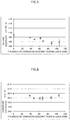
- Fig. 5 is a graph showing a relationship between a thickness and volume resistivity of a corrosion resistant plating layer.
- a horizontal axis indicates the thickness of the corrosion resistant plating layer
- a vertical axis indicates the volume resistivity.
- the bimetal without the corrosion resistant plating layer (reference example) is displayed as a thickness of 0 nm.
- the thickness of the corrosion resistant plating layer was measured using a Glow discharge optical emission spectrometry (GD-OES) method.
- GD-OES Glow discharge optical emission spectrometry
- a device of a model name GD-Profiler 2 (Trade Mark) manufactured by Horiba, Ltd. was used.
- sputtering was started from the surface of the corrosion resistant plating layer (substantially pure Ni) on the side of the high thermal expansion layer (Cu-72 Mn-10 Ni) having a lower content ratio of Ni, and sputtering elapsed time when the Ni content ratio changes greatly was determined.
- the sputtering elapsed time was converted into a sputtering length (depth from the surface) to obtain the thickness of the corrosion resistant plating layer.
- thickness of the corrosion resistant plating layer of each bimetal was measured separately at three arbitrary positions. An average of the thicknesses at the three positions was calculated as the thickness of the corrosion resistant plating layer of each bimetal.
- the thickness of the corrosion resistant plating layer of each bimetal was 0 nm (reference example), 38 nm, 48 nm, 62 nm, 68 nm, 88 nm, and 106 nm respectively.
- the volume resistivity of the bimetal was measured by a four terminal method in accordance with JIS C2525. Three test pieces each having a length of 120 mm and a width of 10 mm were cut out from each of the produced bimetals (total thickness: 0.175 mm) and used for measurement. A measurement temperature was 23°C.
- the thickness of the corrosion resistant plating layer is in a range of 10 nm to 120 nm, and variation in the volume resistivity of the three test pieces cut from each of the bimetals falls within ⁇ 5%. Therefore, it was confirmed that the volume resistivity of the bimetal including the corrosion resistant plating layer having a thickness of 10 nm to 120 nm was slightly different from the volume resistivity of the bimetal without the corrosion resistant plating layer. A result that the variation of the volume resistivity is within ⁇ 5% indicates that the bimetal including the corrosion resistant plating layer having a thickness of 10 nm to 120 nm is suitable for practical use in accordance with JIS Z8703 (see Table 2, tolerance of volume resistivity). As shown in Fig.
- the volume resistivity of the test piece tended to decrease while the thickness of the corrosion resistant plating layer varied along with increase. Therefore, when the thickness of the corrosion resistant plating layer of the bimetal exceeds 120 nm and further increases, it is appropriate that the volume resistivity of the bimetal decreases toward the volume resistivity of the corrosion resistant plating layer (Ni plating layer).
- Fig. 6 is a graph showing a relationship between the thickness and a curvature coefficient of the corrosion resistant plating layer.
- a horizontal axis indicates the thickness of the corrosion resistant plating layer
- a vertical axis indicates the curvature coefficient.
- the bimetal without the corrosion resistant plating layer (reference example) is displayed as a thickness of 0 nm.
- the thickness of the corrosion resistant plating layer was measured using the GD-OES method as described above.
- the curvature coefficient of the bimetal was measured by a measurement method in accordance with JIS C2530. Three test pieces each having a length of 50 mm and a width of 2 mm were cut out from each of the produced bimetals (total thickness: 0.175 mm) and used for measurement. A measurement temperature was 23°C.
- the thickness of the corrosion resistant plating layer is in a range of 10 nm to 120 nm, and variation in the curvature coefficient of the three test pieces cut from each of the bimetals falls within ⁇ 5%. Therefore, it was confirmed that the curvature coefficient of the bimetal including the corrosion resistant plating layer having a thickness of 10 nm to 120 nm was slightly different from the curvature coefficient of the bimetal without the corrosion resistant plating layer. A result that the variation of the curvature coefficient is within ⁇ 5% indicates that the bimetal including the corrosion resistant plating layer having a thickness of 10 nm to 120 nm is suitable for practical use in accordance with JIS Z8703 (see Table 2, tolerance of curvature coefficient).
- the curvature coefficient of the test piece tended not to increase or decrease while the thickness of the corrosion resistant plating layer varied along with increase. Therefore, even when the thickness of the corrosion resistant plating layer of the bimetal exceeds 120 nm and further increases to, for example, about 150 nm, it is understood that a substantial change amount of the curvature coefficient of the bimetal is small.
- a relationship between the thickness and corrosion resistance of the corrosion resistant plating layer of the bimetal was evaluated, in which the thickness of the corrosion resistant plating layer is 0 nm (reference example), 48 nm, 68 nm, 88 nm, and 106 nm.
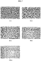
- Fig. 7 is a photograph showing a surface of a high thermal expansion layer after performing a corrosion test on each of the bimetals.
- the bimetal without the corrosion resistant plating layer (reference example) is displayed as a thickness of 0 nm.
- a corrosion test was performed using a saline water spray testing machine manufactured by Suga Test Instruments. Test pieces each having a length of 100 mm and a width of 10 mm were cut out from each of the produced bimetals each having a total thickness of 0.175 mm. The test pieces were used for measurement. A 5% of sodium chloride aqueous solution was sprayed to the bimetal for 60 minutes at a temperature in a spray chamber of 35°C ⁇ 2°C. The surface on the side of the high thermal expansion layer of each bimetal after the test was imaged by a microscope. The micrographs were evaluated by eyes of an expert and divided into three stages of grades 1 to 3 according to a degree of corrosion. Grade 1 shows that corrosion is severe and the bimetal cannot withstand practical use. Grade 2 shows that corrosion is recognized but the corrosion does not affect bimetallic properties. Grade 3 shows that there is little corrosion and the bimetal can withstand practical use sufficiently.
- a bimetal in which the thickness of the corrosion resistant plating layer is 0 nm was evaluated as grade 1.
- a bimetal in which the thickness of the corrosion resistant plating layer is 48 nm and a bimetal in which the thickness of the corrosion resistant plating layer is 68 nm were evaluated as grade 2.
- a bimetal in which the thickness of the corrosion resistant plating layer is 88 nm and a bimetal in which the thickness of the corrosion resistant plating layer is 106 nm were evaluated as grade 3. From this result, it was confirmed that the corrosion resistance was imparted to the bimetal by providing the corrosion resistant plating layer. It was also confirmed that the corrosion resistance of the bimetal improved as the thickness of the corrosion resistant plating layer increased.
Landscapes
- Chemical & Material Sciences (AREA)
- Engineering & Computer Science (AREA)
- Metallurgy (AREA)
- Chemical Kinetics & Catalysis (AREA)
- Materials Engineering (AREA)
- Organic Chemistry (AREA)
- Mechanical Engineering (AREA)
- General Chemical & Material Sciences (AREA)
- Electrochemistry (AREA)
- Physics & Mathematics (AREA)
- Optics & Photonics (AREA)
- Plasma & Fusion (AREA)
- Laminated Bodies (AREA)
- Electroplating Methods And Accessories (AREA)
Abstract
Description
- The present invention relates to a dissimilar metal joined material and a method of manufacturing the same.
- A dissimilar metal joined material such as a bimetal and a trimetal is known. The dissimilar metal joined material is formed by overlapping at least two types of metal different from each other. In such a dissimilar metal joined material, a degree of curvature changes with a temperature change. Therefore, the dissimilar metal joined material is used in various fields of consumer use and industrial use such as thermostats and thermal switches which operate with the temperature change.
-
JP-B-3-57438 - It is required that the dissimilar metal joined material have longer life. Since the dissimilar metal joined material may end life resulting from corrosion, it is required that the dissimilar metal joined material have better corrosion resistance. However, the passive film proposed in
JP-B-3-57438 JP-B-3-57438 - Therefore, an object of the present invention is to provide a dissimilar metal joined material that has corrosion resistance that can prolong life resulting from corrosion and has a small difference from original characteristics.
- According to one aspect of the present invention, there is provided a dissimilar metal joined material including: a clad material including a high thermal expansion layer composed of an alloy containing Mn, and a low thermal expansion layer composed of an alloy containing Ni, the low thermal expansion layer being joined directly to the high thermal expansion layer or via an intermediate layer; and a corrosion resistant plating layer provided on at least a surface of the high thermal expansion layer, the corrosion resistant plating layer having a thickness of 10 nm to 120 nm.
- Another aspect of the present invention provides a method of manufacturing a dissimilar metal joined material, the method includes the successive steps of: degreasing surfaces of a clad material containing a high thermal expansion layer composed of an alloy containing Mn and a low thermal expansion layer composed of an alloy containing Ni, the low thermal expansion layer being joined directly to the high thermal expansion layer or joined via an intermediate layer; washing at least the surface of the high thermal expansion layer; plating at least the surface of the high thermal expansion layer with a plating solution to form a corrosion resistant plating layer having a thickness of 10 nm to 120 nm; removing the plating solution from the surface of the high thermal expansion layer; and drying the dissimilar metal joined material.
- According to the present invention, there is provided a dissimilar metal joined material that has corrosion resistance capable of prolonging life resulting from corrosion and has a small difference from the original characteristics.
-
-
Fig. 1 is a cross-sectional view of a dissimilar metal joined material according to the present embodiment; -
Fig. 2 is a cross-sectional view of a dissimilar metal joined material according toModification 1; -
Fig. 3 is a cross-sectional view of a dissimilar metal joined material according toModification 2; -
Fig. 4 is a cross-sectional view of a dissimilar metal joined material according toModification 3; -
Fig. 5 is a graph showing a relationship between a thickness and volume resistivity of a corrosion resistant plating layer; -
Fig. 6 is a graph showing a relationship between the thickness and a curvature coefficient of the corrosion resistant plating layer; and -
Fig. 7 is a photograph showing a surface of a high thermal expansion layer after performing a corrosion test on a bimetal. - Hereinafter, an embodiment of a dissimilar metal joined material and a method of manufacturing the same will be described with reference to the drawings. The present invention is not limited to these examples but is indicated by a scope of claims, and is intended to include meanings equivalent to the scope of claims and all alterations within the scope. Metal material composition and an element content ratio are indicated by mass%, unless otherwise specified.
-
Fig. 1 is a cross-sectional view of a bimetal 1 (an example of the dissimilar metal joined material) according to the present embodiment. As shown inFig. 1 , thebimetal 1 includes a highthermal expansion layer 2, a lowthermal expansion layer 3, and a corrosionresistant plating layer 4. In the illustrated example, the corrosionresistant plating layer 4, the highthermal expansion layer 2, and the lowthermal expansion layer 3 are stacked in this order. - The high
thermal expansion layer 2 and the lowthermal expansion layer 3 constitute a clad material joined through rolling, diffusion annealing, and the like. The present invention can also be applied to a trimetal (an example of the dissimilar metal joined material) constituted by a clad material formed by adding an intermediate layer (not illustrated) between the highthermal expansion layer 2 and the lowthermal expansion layer 3 and joined through rolling, diffusion annealing, and the like. The clad material without the corrosionresistant plating layer 4 may have a total thickness of 50 µm to 1 mm. In a case of a relatively thin clad material having a total thickness of 50 µm to 0.5 mm, it is considered that the corrosion has a large impact, and thus it is particularly effective to form the corrosionresistant plating layer 4 to obtain corrosion resistance. - The high
thermal expansion layer 2 is composed of an alloy (metal) containing Mn (material of the highthermal expansion layer 2 constituting raw material plate). Mn is expected to increase the thermal expansion coefficient. By intentionally adding Mn to the highthermal expansion layer 2, it is configured such that a thermal expansion coefficient of the highthermal expansion layer 2 is larger than that of the lowthermal expansion layer 3. - The high
thermal expansion layer 2 may be an Fe-Ni-Mn based alloy containing Mn. The highthermal expansion layer 2 may contain 15% to 30% of Ni, preferably 20% to 26% of Ni, and more preferably 22% to 24% of Ni. The highthermal expansion layer 2 may contain 2% to 10% of Mn, preferably 5% to 6% of Mn. The highthermal expansion layer 2 may contain the balance of Fe and unavoidable impurities. - The high
thermal expansion layer 2 may be an Cu-Mn-Ni based alloy containing Mn. The highthermal expansion layer 2 may contain 60% to 80% of Mn, preferably 65% to 75% of Mn, and more preferably 70% to 73% of Mn. The highthermal expansion layer 2 may contain 5% to 20% of Ni, preferably 7% to 15% of Ni, and more preferably 9% to 11% of Ni. The highthermal expansion layer 2 may contain the balance of Cu and unavoidable impurities. - Examples of the material of the high
thermal expansion layer 2 constituting raw material plate include the Fe-Ni-Mn based alloy and the Cu-Mn-Ni based alloy, and TM1 (Mn-Cu-Ni based such as Mn-8 Cu-20 Ni), TM2, and TM4 to TM6 (Fe-Ni-Mn based) in accordance with JIS C2530. If the raw material plate (high thermal expansion layer) is composed of such material (alloy composition), an average thermal expansion coefficient from 30°C to 100°C can be set within a range of 18 × 10-6/°C to 28.5 × 10⁻⁶/°C by selection of the material, which is suitable for a bimetal and a trimetal since thermal expansion is large when heat is generated by excessive energization. A thickness of the highthermal expansion layer 2 may be 50% to 60% of the total thickness of the clad material without the corrosionresistant plating layer 4. For example, the thickness of the highthermal expansion layer 2 may be 25 µm to 0.6 mm. - The low
thermal expansion layer 3 is composed of an alloy (metal) containing Ni (material of the lowthermal expansion layer 3 constituting raw material plate). Elements such as Mn and Cu may increase the thermal expansion coefficient. Although the elements such as Mn and Cu may be included as unavoidable impurities. However, by intentionally not adding the elements such as Mn and Cu to the alloy, it is configured such that the thermal expansion coefficient of the lowthermal expansion layer 3 is smaller than that of the highthermal expansion layer 2. - The low
thermal expansion layer 3 may be an Fe-Ni based alloy containing Ni. The lowthermal expansion layer 3 may contain 30% to 60% of Ni, preferably 33% to 55% of Ni, and more preferably 33% to 51% of Ni. The lowthermal expansion layer 3 may contain the balance of Fe and unavoidable impurities. - Examples of the material of the low
thermal expansion layer 3 constituting raw material plate include the Fe-Ni based alloy such as Fe-42 Ni based (42 alloy) or Fe-36 Ni based (36 alloy), and an alloy such as Fe-29 Ni-17 Co, Fe-36 Ni-12 Cr, Fe-36 Ni-9 Cr, Fe-42 Ni-5.5 Cr-1 Ti, and Fe-43 Ni-5 Cr-3 Ti-1 Co. - If the raw material plate (low thermal expansion layer) is composed of such material (alloy composition), an average thermal expansion coefficient from 30°C to 100°C can be set within a range of 0.5 × 10⁻⁶/°C to 11.0 × 10⁻⁶/°C by selection of the material, which is suitable for a bimetal and a trimetal since thermal expansion is small when heat is generated by excessive energization. A difference between an average thermal expansion coefficient of the low thermal expansion layer and that of the high thermal expansion layer from 30°C to 100°C can be set within a range of 7 × 10⁻⁶/°C to 28 × 10-6/°C by selection of combination of the low thermal expansion layer and the high thermal expansion layer, which is suitable for the bimetal and the trimetal since a curvature coefficient can be selected variously. A thickness of the low
thermal expansion layer 3 may be 40% to 50% of the total thickness of the clad material without the corrosionresistant plating layer 4. For example, the thickness of the lowthermal expansion layer 3 may be 20 µm to 0.5 mm. - The corrosion
resistant plating layer 4 is a plating layer composed of a metal that can be expected to have corrosion resistance. The corrosionresistant plating layer 4 may be provided on at least a surface of the highthermal expansion layer 2. The surface of the highthermal expansion layer 2 corresponds to one face of the highthermal expansion layer 2 that is opposite to the other face to which the lowthermal expansion layer 3 is joined, or to which the intermediate layer is bonded. It is considered that Ni-based plating layer such as a nickel plating layer (Ni plating layer), a nickel phosphorus plating layer (Ni-P plating layer), a nickel boron plating layer (Ni-B plating layer) and a nickel chromium (trivalent) plating layer (Ni-trivalent Cr plating layer), may be applied to the corrosionresistant plating layer 4. Any of the Ni-based plating layer are excellent in corrosion resistance. As an example, the Ni plating layer has small electrical resistance. The Ni plating layer formed by an electrolytic plating treatment has smaller electrical resistance. The Ni-P plating layer containing, for example, 2 mass% to 13 mass% of P improves corrosion resistance (in particular, acid resistance) as an amount of P increases. The Ni-B plating layer containing, for example, 0.3 mass% to 1 mass % of B has advantages such as being difficult to be surface oxidized and being difficult to change color even heated, having resistivity as small as 5 µΩ·cm to 7 µΩ·cm for example, and having good soldering properties. - The corrosion
resistant plating layer 4 is preferably a Ni plating layer. The Ni plating layer can be easily produced by an electrolytic Ni plating treatment (also referred to as Ni electroplating treatment) or an electroless Ni plating treatment. In general, the Ni electroplating treatment is preferable since treatment time is short and cost can be reduced as compared with the electroless Ni plating treatment. The corrosionresistant plating layer 4 has a thickness of 10 nm to 120 nm. Since the corrosionresistant plating layer 4 has a thickness of 10 nm to 120 nm, rigidity of the corrosionresistant plating layer 4 is extremely small as compared with the highthermal expansion layer 2 composed of an alloy containing Mn and the lowthermal expansion layer 3 composed of an alloy containing Mn. Therefore, even if the corrosionresistant plating layer 4 is formed, the curvature coefficient of the bimetal 1 is difficult to change. That is, the bimetal 1 including the corrosionresistant plating layer 4 according to the present embodiment can have a curvature coefficient close to the curvature coefficient of the bimetal without the corrosion resistant plating layer. - Since the corrosion
resistant plating layer 4 has a thickness of 10 nm to 120 nm, a change in volume resistivity due to the corrosionresistant plating layer 4 is extremely small as compared with the bimetal composed of the high thermal expansion layer and the low thermal expansion layer without the corrosion resistant plating layer. Therefore, when the bimetal 1 is to be energized, a current can flow through the highthermal expansion layer 2 and the lowthermal expansion layer 3. Therefore, even if the corrosionresistant plating layer 4 is formed, the volume resistivity of the bimetal 1 is difficult to change. That is, the bimetal 1 including the corrosionresistant plating layer 4 according to the present embodiment can have volume resistivity close to the volume resistivity of the bimetal without the corrosion resistant plating layer. - In this manner, the
bimetal 1 of the present embodiment including the corrosionresistant plating layer 4 having a thickness of 10 nm to 120 nm can prolong life resulting from corrosion by the corrosionresistant plating layer 4, and a difference from characteristics of an original bimetal having no corrosion resistant plating layer is small. The corrosion resistance of the bimetal 1 can be improved by increasing the thickness of the corrosionresistant plating layer 4 to 20 nm, 30 nm, and 40 nm, for example. The difference between the characteristics of the bimetal 1 and the characteristics of the original bimetal without the corrosion resistant plating layer can be reduced by reducing the thickness of the corrosionresistant plating layer 4 to 110 nm, 100 nm, 90 nm, 80 nm, and 70 nm, for example. From such a viewpoint, by setting the thickness of the corrosionresistant plating layer 4 to, for example, 30 nm to 80 nm (or 40 nm to 70 nm), the life resulting from corrosion can be further prolonged, and the difference from the characteristics (volume resistivity) of the original bimetal without the corrosion resistant plating layer becomes smaller. - Metal constituting the high
thermal expansion layer 2 is composed of an alloy containing Mn for the reason described above. Since the alloy containing Mn easily corrodes in general, the highthermal expansion layer 2 easily corrodes than the lowthermal expansion layer 3 composed of the alloy containing no Mn but containing Ni for the reason described above. Therefore, corrosion of the bimetal 1 advances from the highthermal expansion layer 2. In order to suppress deterioration due to the corrosion of the bimetal 1, it is considered that a passive film may be provided on the surface of the highthermal expansion layer 2 as inJP-B-3-57438 thermal expansion layer 2 is larger than that of the lowthermal expansion layer 3, dimensions change greatly due to temperature change. Therefore, when a passive film is provided on the surface of the highthermal expansion layer 2, it is noticed that the passive film cannot follow dimensional change of the highthermal expansion layer 2, and the passive film easily cracks. Further, it is noticed that the corrosion of the highthermal expansion layer 2 rapidly proceeds from a portion where the passive film cracks. - Therefore, according to the bimetal 1 according to the present embodiment, the corrosion
resistant plating layer 4 having a thickness of 10 nm to 120 nm is provided on the surface of the highthermal expansion layer 2. The corrosionresistant plating layer 4 having a small thickness and composed of metal has a higher thermal expansion coefficient and a smaller elastic coefficient than the passive film which is a hard and brittle film of metal oxide. Therefore, the corrosionresistant plating layer 4 easily follows a dimensional change of the highthermal expansion layer 2, and is difficult to crack even if the temperature change repeatedly acts on thebimetal 1. Therefore, the bimetal 1 according to the present embodiment on which the corrosionresistant plating layer 4 having a thickness of 10 nm to 120 nm is provided on the surface of the highthermal expansion layer 2 is difficult to corrode and has long life by preventing from the corrosion. - Although
Fig. 1 describes a configuration in which the corrosionresistant plating layer 4 is provided only on the surface of the highthermal expansion layer 2, the present invention is not limited to this example. As shown inFig. 2 , the corrosionresistant plating layer 4 may be provided so as to cover the surface of the highthermal expansion layer 2 and a side surface of thebimetal 1. Alternatively, as shown inFig. 3 , the corrosionresistant plating layer 4 may be provided on the surface of the highthermal expansion layer 2 and on the surface of the lowthermal expansion layer 3, respectively. Further, as shown inFig. 4 , the corrosionresistant plating layer 4 may be provided so as to cover an entire surface of thebimetal 1. - Although the bimetal 1 where the high
thermal expansion layer 2 is directly joined to the lowthermal expansion layer 3 is shown in examples shown inFig. 1 to Fig. 4 , the present invention may be applied to the trimetal where the highthermal expansion layer 2 is joined to the lowthermal expansion layer 3 via the intermediate layer. Even when the present invention is applied to the trimetal, the corrosionresistant plating layer 4 having a thickness of 10 nm to 120 nm is provided on at least the surface of the highthermal expansion layer 2. Examples of the material of the raw material plate constituting the intermediate layer can include Cu (pure Cu) or a Cu alloy (a heat resistant Cu alloy or the like), Ni (pure Ni) or a Ni alloy, a Ni-Cu based alloy, and a Zr-Cu based alloy. - In many cases, the
bimetal 1 is distributed to the market with anidentification mark 5 provided thereon. Theidentification mark 5 is used to identify a surface on a side of the highthermal expansion layer 2 or the lowthermal expansion layer 3 when the bimetal 1 is handled. InFig. 1 to Fig. 4 , the identification mark is represented by areference numeral 5. - As shown in
Fig. 1 andFig. 3 , theidentification mark 5 can be provided on the surface of the corrosionresistant plating layer 4 on the side of the highthermal expansion layer 2. Alternatively, as shown inFig. 2 , theidentification mark 5 can be provided on the surface of the lowthermal expansion layer 3 exposed to the outside. Alternatively, as shown inFig. 4 , theidentification mark 5 can be provided on the surface of the corrosionresistant plating layer 4 on the side of the lowthermal expansion layer 3. - The
identification mark 5 can be formed by a method such as acid etching, ink printing (ink jet printer or the like), laser irradiation (laser marking), or engraving. It is preferable that theidentification mark 5 is formed by ink printing that does not substantially wound the surface of the bimetal 1 or acid etching that relatively shallowly wounds the surface of thebimetal 1. It should be noted that when theidentification mark 5 is formed by laser irradiation or engraving, thethermal expansion layer 2 or the lowthermal expansion layer 3, which is a base of the corrosionresistant plating layer 4 forming theidentification mark 5, may be wounded and mechanical properties may be changed, and the curvature coefficient of the bimetal 1 may change. - Although not illustrated, it is also possible to provide the
identification mark 5 on the surface of the highthermal expansion layer 2 or the lowthermal expansion layer 3 covered with the corrosionresistant plating layer 4. In this case, when the thickness of the corrosionresistant plating layer 4 increases, theidentification mark 5 may be unclear or difficult to transmit and difficult to read. Therefore, theidentification mark 5 is preferably provided on the surface of the corrosionresistant plating layer 4 or on the surface of the lowthermal expansion layer 3 exposed to the outside. - A method of manufacturing the
bimetal 1 will be described below. - The clad material where the high
thermal expansion layer 2 is joined to the lowthermal expansion layer 3 is produced. The clad material can be produced by a general clad rolling technique. First, two types of raw material plates including the highthermal expansion layer 2 constituting raw material plate and the lowthermal expansion layer 3 constituting raw material plate, each having a predetermined thickness and adjusted to elongation and hardness suitable for clad rolling, are prepared by softening annealing, temper rolling, or the like. Next, the two types of raw material plates are clad rolled and annealed appropriately to produce the clad material having a predetermined thickness. During the clad rolling, diffusion annealing (heat treatment) is performed for increasing bonding strength by diffusion action of elements when the clad material has an appropriate thickness. Further, even after the diffusion annealing is performed, it is possible to reduce the thickness by further rolling as necessary. By performing such clad rolling, the two types of raw material plates that are the highthermal expansion layer 2 and the lowthermal expansion layer 3 are joined and thinned to produce the clad material having a predetermined thickness. - Next, a degreasing treatment that degreases the surface of the clad material having a total thickness of, for example, 50 µm to 1 mm that is obtained in this manner is performed. In the degreasing treatment, the clad material is immersed in a degreasing solution having a temperature of about 10°C to 80°C for about 20 seconds. The degreasing solution may be showered on the clad material. Such a degreasing treatment may be a continuous treatment of degreasing a hoop clad material as it is, or the clad material may be diced and then degreased by a barrel treatment.
- Next, a surface washing treatment is performed, in which the degreasing solution used in the degreasing treatment is removed from the surface of the clad material. In the washing treatment, water having a temperature of about 10°C to 80°C may be showered on the clad material for about 10 seconds. The clad material may be immersed in the water having a temperature of about 10°C to 80°C for about 10 seconds. Such a washing treatment may be a continuous treatment of washing the hoop clad material as it is, or the clad material may be diced and then washed by a barrel treatment.
- Further, a corrosion resistant plating treatment is performed, in which the corrosion
resistant plating layer 4 is provided on at least the surface of the highthermal expansion layer 2 of the clad material. The corrosionresistant plating layer 4 having a thickness of 10 nm to 120 nm is formed on at least the surface of the highthermal expansion layer 2 by the corrosion resistant plating treatment. - The corrosion resistant plating treatment may be an electrolytic plating treatment considered to be preferable as described above. The electrolytic plating treatment may be performed for about 2 seconds using the Ni electroplating solution having a pH of about 4.5 to 6.0 and a temperature of 20°C to 35°C. When the corrosion
resistant plating layer 4 is formed by using such an electrolytic plating treatment, a continuous treatment of plating the hoop clad material as it is may be used, or the clad material may be diced and then plated by a barrel treatment. As to the corrosion resistant plating treatment, a Ni electroplating treatment is preferable in view of reducing treatment time and treatment cost, but an electroless plating treatment is preferable when dimensional accuracy of the thickness of the plating film be improved. - At this time, in the bimetal 1 shown in
Fig. 1 , side surfaces of the clad material and the surface of the lowthermal expansion layer 3 are masked, and the corrosionresistant plating layer 4 is formed only on the surface of the highthermal expansion layer 2. In the bimetal 1 shown inFig. 2 , the side surfaces of the clad material are not masked, the surface of the lowthermal expansion layer 3 is masked, and the corrosionresistant plating layer 4 is formed on the side surfaces of the clad material and the surface of the highthermal expansion layer 2. In the bimetal 1 shown inFig. 3 , side surfaces of the clad material are masked, and the corrosionresistant plating layer 4 is formed on the surface of the highthermal expansion layer 2 and on the surface of the lowthermal expansion layer 3. In the bimetal 1 shown inFig. 4 , the clad material is not masked, and the corrosionresistant plating layer 4 is formed on an entire surface including the surface of the highthermal expansion layer 2 and the surface of the lowthermal expansion layer 3. - Next, a plating solution removing treatment is performed, in which a plating solution is removed from at least the surface of the high
thermal expansion layer 2. In the plating solution removing treatment, water having a temperature of about 10°C to 80°C may be showered on the clad material for about 10 seconds. The clad material may be immersed in the water having the temperature of about 10°C to 80°C for about 10 seconds. In such a plating solution removing treatment, the hoop clad material may be continuously treated as it is, or a barrel treatment may be performed after the clad material is diced. - Next, a drying treatment of drying the clad material is performed. The drying treatment is performed for about 10 seconds in a warm air bath (may be put in a heat retention furnace) by a hot wind having a temperature of about 100°C to 150°C. In such a drying treatment, the hoop clad material may be continuously treated as it is and dried, or the clad material may be diced and then dried by a barrel treatment.
- It is preferable to provide the
identification mark 5 after the corrosionresistant plating layer 4 is formed. Theidentification mark 5 may be formed on the surface of the highthermal expansion layer 2 or on the surface of the lowthermal expansion layer 3. - The
identification mark 5 can be provided by a method such as acid etching or ink printing (using ink jet printer). It is preferable to provide theidentification mark 5 by acid etching on the surface of the highthermal expansion layer 2. This is because the highthermal expansion layer 2 composed of an alloy containing Mn easily corrodes by acid etching, and theidentification mark 5 that is clearly colored by corrosion (oxidation) is obtained. - Even before or after the corrosion resistant plating treatment is performed on the clad material, and even before or after the
identification mark 5 is formed, slit processing or dice processing can be performed. In the slit processing, the clad material is cut along a longitudinal direction (generally a rolling direction) to obtain a processing material having a predetermined dimension (width). The dice processing is processing in which the clad material is cut along a width direction (generally a direction orthogonal to the rolling direction) to obtain a processing material having a predetermined dimension (length). - A bimetal having a length of 100 m, a width of 70 mm, a total thickness of 0.175 mm was produced. The bimetal includes a high thermal expansion layer having an average thermal expansion coefficient of about 27.7 × 10⁻⁶/°C from 30°C to 100°C which contains a Cu-Mn-Ni based metal (Cu-72 Mn-10 Ni), and a low thermal expansion layer having an average thermal expansion coefficient of about 1.3 × 10⁻⁶/°C from 30°C to 100°C which contains an Fe-Ni based metal (Fe-36 Ni). A thickness of the high thermal expansion layer was 0.093 mm, and a thickness of the low thermal expansion layer was 0.082 mm.
- The bimetal was produced by the following process.
- As a production process of the clad material constituting the bimetal, a raw material plate containing the metal of Cu-72 Mn-10 Ni and a raw material plate containing the metal of Fe-36 Ni were prepared, and clad rolling was performed by laminating the two types of raw material plates in a thickness direction to finally produce a clad material having a total thickness of 0.175 mm (the thickness of the high thermal expansion layer was 0.093 mm, and the thickness of the low thermal expansion layer was 0.082 mm). In the clad rolling, diffusion annealing was performed while repeating rolling and softening annealing as necessary to strengthen bonding, and the total thickness of the clad material was adjusted by finish rolling.
- As the degreasing treatment, a degreasing solution having a temperature of 28°C and containing 1.0 mass% of potassium hydroxide was sprayed onto an entire surface of the clad material by spraying.
- As the washing treatment, pure water having a temperature of 28°C was sprayed onto the entire surface of the clad material by spraying.
- As the corrosion resistant plating treatment, the electrolytic plating treatment is considered to be preferable as described above. The Ni electroplating was performed using a plating solution at a temperature of 28°C containing 250 g/L of nickel sulfate, 40 g/L of nickel chloride, and 40 g/L of boric acid and adjusted to pH 4.7. By the Ni electroplating, a corrosion resistant plating layer (Ni plating layer) composed of Ni was formed on a surface of the high thermal expansion layer.
- As the plating solution removing treatment, pure water having a temperature of 28°C was sprayed onto the entire surface of the clad material including the corrosion resistant plating layer by spraying.
- As the drying treatment, hot wind having a temperature of 100°C to 120°C was blown onto the entire surface of the clad material including the corrosion resistant plating layer.
- An identification mark was provided on a surface of the corrosion resistant plating layer on a side of the high thermal expansion layer by acid etching.
- By such a process, various bimetals including different thicknesses of the corrosion resistant plating layers were produced. As a reference example, a bimetal without the corrosion resistant plating layer (a thickness of the corrosion resistant plating layer is 0 nm) was also produced.
- Next, a relationship between the thickness and the volume resistivity of the corrosion resistant plating layer of the various bimetals produced as described above was evaluated.
Fig. 5 is a graph showing a relationship between a thickness and volume resistivity of a corrosion resistant plating layer. InFig. 5 , a horizontal axis indicates the thickness of the corrosion resistant plating layer, and a vertical axis indicates the volume resistivity. InFig. 5 , the bimetal without the corrosion resistant plating layer (reference example) is displayed as a thickness of 0 nm. - The thickness of the corrosion resistant plating layer was measured using a Glow discharge optical emission spectrometry (GD-OES) method. In this measurement, a device of a model name GD-Profiler 2 (Trade Mark) manufactured by Horiba, Ltd. was used.
-
- Method: Pulse sputtering
- Measurement diameter: ϕ 7 mm
- Output: 35 W
- Frequency: 100 Hz
- Ar gas pressure: 600 Pa
- In the above measurement, sputtering was started from the surface of the corrosion resistant plating layer (substantially pure Ni) on the side of the high thermal expansion layer (Cu-72 Mn-10 Ni) having a lower content ratio of Ni, and sputtering elapsed time when the Ni content ratio changes greatly was determined. The sputtering elapsed time was converted into a sputtering length (depth from the surface) to obtain the thickness of the corrosion resistant plating layer.
- According to the measurement method, thickness of the corrosion resistant plating layer of each bimetal was measured separately at three arbitrary positions. An average of the thicknesses at the three positions was calculated as the thickness of the corrosion resistant plating layer of each bimetal. The thickness of the corrosion resistant plating layer of each bimetal was 0 nm (reference example), 38 nm, 48 nm, 62 nm, 68 nm, 88 nm, and 106 nm respectively.
- The volume resistivity of the bimetal was measured by a four terminal method in accordance with JIS C2525. Three test pieces each having a length of 120 mm and a width of 10 mm were cut out from each of the produced bimetals (total thickness: 0.175 mm) and used for measurement. A measurement temperature was 23°C.
- As shown in
Fig. 5 , the thickness of the corrosion resistant plating layer is in a range of 10 nm to 120 nm, and variation in the volume resistivity of the three test pieces cut from each of the bimetals falls within ± 5%. Therefore, it was confirmed that the volume resistivity of the bimetal including the corrosion resistant plating layer having a thickness of 10 nm to 120 nm was slightly different from the volume resistivity of the bimetal without the corrosion resistant plating layer. A result that the variation of the volume resistivity is within ± 5% indicates that the bimetal including the corrosion resistant plating layer having a thickness of 10 nm to 120 nm is suitable for practical use in accordance with JIS Z8703 (see Table 2, tolerance of volume resistivity). As shown inFig. 5 , it was confirmed that the volume resistivity of the test piece tended to decrease while the thickness of the corrosion resistant plating layer varied along with increase. Therefore, when the thickness of the corrosion resistant plating layer of the bimetal exceeds 120 nm and further increases, it is appropriate that the volume resistivity of the bimetal decreases toward the volume resistivity of the corrosion resistant plating layer (Ni plating layer). - Next, a relationship between the thickness and the curvature coefficient of the corrosion resistant plating layer of the bimetal produced as described above was evaluated.
Fig. 6 is a graph showing a relationship between the thickness and a curvature coefficient of the corrosion resistant plating layer. InFig. 6 , a horizontal axis indicates the thickness of the corrosion resistant plating layer, and a vertical axis indicates the curvature coefficient. InFig. 6 , the bimetal without the corrosion resistant plating layer (reference example) is displayed as a thickness of 0 nm. - The thickness of the corrosion resistant plating layer was measured using the GD-OES method as described above. The curvature coefficient of the bimetal was measured by a measurement method in accordance with JIS C2530. Three test pieces each having a length of 50 mm and a width of 2 mm were cut out from each of the produced bimetals (total thickness: 0.175 mm) and used for measurement. A measurement temperature was 23°C.
- As shown in
Fig. 6 , the thickness of the corrosion resistant plating layer is in a range of 10 nm to 120 nm, and variation in the curvature coefficient of the three test pieces cut from each of the bimetals falls within ± 5%. Therefore, it was confirmed that the curvature coefficient of the bimetal including the corrosion resistant plating layer having a thickness of 10 nm to 120 nm was slightly different from the curvature coefficient of the bimetal without the corrosion resistant plating layer. A result that the variation of the curvature coefficient is within ± 5% indicates that the bimetal including the corrosion resistant plating layer having a thickness of 10 nm to 120 nm is suitable for practical use in accordance with JIS Z8703 (see Table 2, tolerance of curvature coefficient). As shown inFig. 6 , it was confirmed that the curvature coefficient of the test piece tended not to increase or decrease while the thickness of the corrosion resistant plating layer varied along with increase. Therefore, even when the thickness of the corrosion resistant plating layer of the bimetal exceeds 120 nm and further increases to, for example, about 150 nm, it is understood that a substantial change amount of the curvature coefficient of the bimetal is small. - Next, a relationship between the thickness and corrosion resistance of the corrosion resistant plating layer of the bimetal was evaluated, in which the thickness of the corrosion resistant plating layer is 0 nm (reference example), 48 nm, 68 nm, 88 nm, and 106 nm.
Fig. 7 is a photograph showing a surface of a high thermal expansion layer after performing a corrosion test on each of the bimetals. InFig. 7 , the bimetal without the corrosion resistant plating layer (reference example) is displayed as a thickness of 0 nm. - A corrosion test was performed using a saline water spray testing machine manufactured by Suga Test Instruments. Test pieces each having a length of 100 mm and a width of 10 mm were cut out from each of the produced bimetals each having a total thickness of 0.175 mm. The test pieces were used for measurement. A 5% of sodium chloride aqueous solution was sprayed to the bimetal for 60 minutes at a temperature in a spray chamber of 35°C ± 2°C. The surface on the side of the high thermal expansion layer of each bimetal after the test was imaged by a microscope. The micrographs were evaluated by eyes of an expert and divided into three stages of
grades 1 to 3 according to a degree of corrosion.Grade 1 shows that corrosion is severe and the bimetal cannot withstand practical use.Grade 2 shows that corrosion is recognized but the corrosion does not affect bimetallic properties.Grade 3 shows that there is little corrosion and the bimetal can withstand practical use sufficiently. - As shown in
Fig. 7 , a bimetal in which the thickness of the corrosion resistant plating layer is 0 nm (reference example) was evaluated asgrade 1. A bimetal in which the thickness of the corrosion resistant plating layer is 48 nm and a bimetal in which the thickness of the corrosion resistant plating layer is 68 nm were evaluated asgrade 2. A bimetal in which the thickness of the corrosion resistant plating layer is 88 nm and a bimetal in which the thickness of the corrosion resistant plating layer is 106 nm were evaluated asgrade 3. From this result, it was confirmed that the corrosion resistance was imparted to the bimetal by providing the corrosion resistant plating layer. It was also confirmed that the corrosion resistance of the bimetal improved as the thickness of the corrosion resistant plating layer increased.
Claims (6)
- A dissimilar metal bonded material comprising:a clad material comprising:a high thermal expansion layer composed of an alloy containing Mn, anda low thermal expansion layer composed of an alloy containing Ni, the low thermal expansion layer being joined directly to the high thermal expansion layer or joined via an intermediate layer; anda corrosion resistant plating layer provided on at least a surface of the high thermal expansion layer, the corrosion resistant plating layer having a thickness of 10 nm to 120 nm.
- The dissimilar metal bonded material according to claim 1, wherein
the corrosion resistant plating layer is any one of a Ni plating layer, a Ni-B plating layer, a Ni-trivalent Cr plating layer, or a Ni-P plating layer. - The dissimilar metal joined material according to claim 2, wherein
the corrosion resistant plating layer is a Ni plating layer. - The dissimilar metal joined material according to any one of claims 1 to 3, further comprising an identification mark provided on a surface thereof.
- A method of manufacturing a dissimilar metal joined material, the method comprising the successive steps of:degreasing surfaces of a clad material comprising: a high thermal expansion layer composed of an alloy containing Mn and a low thermal expansion layer composed of an alloy containing Ni, the low thermal expansion layer being joined directly to the high thermal expansion layer or joined via an intermediate layer;washing at least the surface of the high thermal expansion layer;plating at least the surface of the high thermal expansion layer with a plating solution to form a corrosion resistant plating layer having a thickness of 10 nm to 120 nm;removing the plating solution from the surface of the high thermal expansion layer; anddrying the dissimilar metal joined material.
- The method of manufacturing a dissimilar metal joined material according to claim 5,
wherein the plating solution has a pH of 4.5 to 6.0.
Applications Claiming Priority (2)
| Application Number | Priority Date | Filing Date | Title |
|---|---|---|---|
| JP2018088838 | 2018-05-02 | ||
| JP2019003185A JP6924785B2 (en) | 2018-05-02 | 2019-01-11 | Dissimilar metal bonding material and its manufacturing method |
Publications (2)
| Publication Number | Publication Date |
|---|---|
| EP3564028A1 true EP3564028A1 (en) | 2019-11-06 |
| EP3564028B1 EP3564028B1 (en) | 2021-06-09 |
Family
ID=66334183
Family Applications (1)
| Application Number | Title | Priority Date | Filing Date |
|---|---|---|---|
| EP19169284.7A Active EP3564028B1 (en) | 2018-05-02 | 2019-04-15 | Dissimilar metal joined material and method of manufacturing same |
Country Status (2)
| Country | Link |
|---|---|
| US (1) | US20190337086A1 (en) |
| EP (1) | EP3564028B1 (en) |
Cited By (2)
| Publication number | Priority date | Publication date | Assignee | Title |
|---|---|---|---|---|
| CN111408720A (en) * | 2020-04-29 | 2020-07-14 | 西北工业大学 | Laser additive manufacturing method for metal parts made of iron-nickel-manganese-copper dissimilar materials |
| CN114563481A (en) * | 2021-04-01 | 2022-05-31 | 北京航空航天大学 | Damage monitoring and online maintenance system for metal material structure |
Families Citing this family (3)
| Publication number | Priority date | Publication date | Assignee | Title |
|---|---|---|---|---|
| JP6923099B1 (en) * | 2021-03-23 | 2021-08-18 | 秋田県 | Dissimilar metal joints and their manufacturing methods |
| CA3191610A1 (en) * | 2022-03-07 | 2023-09-07 | Syncrude Canada Ltd. In Trust For The Owners Of The Syncrude Project As Such Owners Exist Now And In The Future | Friction welding of cladded cemented or sintered carbides to a structural element |
| WO2026090485A1 (en) * | 2024-10-24 | 2026-04-30 | Ohio State Innovation Foundation | Intermediate steel alloy for joining dissimilar metals and uses thereof |
Citations (11)
| Publication number | Priority date | Publication date | Assignee | Title |
|---|---|---|---|---|
| US2349577A (en) * | 1941-11-21 | 1944-05-23 | Chicago Dev Co | Control member |
| US3219423A (en) * | 1963-01-09 | 1965-11-23 | Texas Instruments Inc | Composite thermostatic materials and thermostats made therefrom |
| US3646591A (en) * | 1968-12-18 | 1972-02-29 | Texas Instruments Inc | Method for making thermostat metal |
| US3707359A (en) * | 1970-11-17 | 1972-12-26 | Texas Instruments Inc | Composite thermostatic metal laminate |
| US3708863A (en) * | 1970-07-23 | 1973-01-09 | Johnson Service Co | Method of making a temperature sensing element |
| US3788821A (en) * | 1970-12-21 | 1974-01-29 | Texas Instruments Inc | Composite thermostat material |
| US3865559A (en) * | 1974-01-30 | 1975-02-11 | Texas Instruments Inc | Composite thermostat metal |
| US3902867A (en) * | 1974-07-01 | 1975-09-02 | Texas Instruments Inc | Oxide dispersed high purity nickel for use in thermostat metals |
| JPS62209381A (en) * | 1986-03-11 | 1987-09-14 | 住友特殊金属株式会社 | Manufacture of bimetal |
| US5573860A (en) * | 1993-12-27 | 1996-11-12 | Sumitomo Special Metals Co., Ltd. | Bimetal |
| US20120077056A1 (en) * | 2009-06-11 | 2012-03-29 | Neomax Materials Co., Ltd. | High-temperature bimetal |
Family Cites Families (3)
| Publication number | Priority date | Publication date | Assignee | Title |
|---|---|---|---|---|
| US4655884A (en) * | 1985-08-19 | 1987-04-07 | General Electric Company | Nickel plating of refractory metals |
| DE69102553T2 (en) * | 1990-02-09 | 1994-10-20 | Nihon Parkerizing | Process for the surface treatment of titanium-containing metal objects. |
| JP2018133171A (en) * | 2017-02-14 | 2018-08-23 | Littelfuseジャパン合同会社 | Thermosensitive operation element |
-
2019
- 2019-04-15 EP EP19169284.7A patent/EP3564028B1/en active Active
- 2019-04-17 US US16/386,672 patent/US20190337086A1/en not_active Abandoned
Patent Citations (12)
| Publication number | Priority date | Publication date | Assignee | Title |
|---|---|---|---|---|
| US2349577A (en) * | 1941-11-21 | 1944-05-23 | Chicago Dev Co | Control member |
| US3219423A (en) * | 1963-01-09 | 1965-11-23 | Texas Instruments Inc | Composite thermostatic materials and thermostats made therefrom |
| US3646591A (en) * | 1968-12-18 | 1972-02-29 | Texas Instruments Inc | Method for making thermostat metal |
| US3708863A (en) * | 1970-07-23 | 1973-01-09 | Johnson Service Co | Method of making a temperature sensing element |
| US3707359A (en) * | 1970-11-17 | 1972-12-26 | Texas Instruments Inc | Composite thermostatic metal laminate |
| US3788821A (en) * | 1970-12-21 | 1974-01-29 | Texas Instruments Inc | Composite thermostat material |
| US3865559A (en) * | 1974-01-30 | 1975-02-11 | Texas Instruments Inc | Composite thermostat metal |
| US3902867A (en) * | 1974-07-01 | 1975-09-02 | Texas Instruments Inc | Oxide dispersed high purity nickel for use in thermostat metals |
| JPS62209381A (en) * | 1986-03-11 | 1987-09-14 | 住友特殊金属株式会社 | Manufacture of bimetal |
| JPH0357438B2 (en) | 1986-03-11 | 1991-09-02 | Sumitomo Spec Metals | |
| US5573860A (en) * | 1993-12-27 | 1996-11-12 | Sumitomo Special Metals Co., Ltd. | Bimetal |
| US20120077056A1 (en) * | 2009-06-11 | 2012-03-29 | Neomax Materials Co., Ltd. | High-temperature bimetal |
Cited By (3)
| Publication number | Priority date | Publication date | Assignee | Title |
|---|---|---|---|---|
| CN111408720A (en) * | 2020-04-29 | 2020-07-14 | 西北工业大学 | Laser additive manufacturing method for metal parts made of iron-nickel-manganese-copper dissimilar materials |
| CN111408720B (en) * | 2020-04-29 | 2020-12-15 | 西北工业大学 | A kind of iron-nickel-manganese-copper dissimilar material metal parts laser additive manufacturing method |
| CN114563481A (en) * | 2021-04-01 | 2022-05-31 | 北京航空航天大学 | Damage monitoring and online maintenance system for metal material structure |
Also Published As
| Publication number | Publication date |
|---|---|
| US20190337086A1 (en) | 2019-11-07 |
| EP3564028B1 (en) | 2021-06-09 |
Similar Documents
| Publication | Publication Date | Title |
|---|---|---|
| EP3564028B1 (en) | Dissimilar metal joined material and method of manufacturing same | |
| KR102518795B1 (en) | Aluminized steel sheet, hot-stamped member and manufacturing method of hot-stamped member | |
| US9616411B2 (en) | High Al-content steel sheet excellent in workability and method of production of same | |
| CN105960484B (en) | The copper alloy lath of the belt surface clad of excellent heat resistance | |
| JP6924785B2 (en) | Dissimilar metal bonding material and its manufacturing method | |
| KR20210005220A (en) | Zn-Al-Mg-based hot-dip plated steel sheet and its manufacturing method | |
| TW201002165A (en) | Copper foil for printed circuit board and copper clad laminate plate for printed circuit board | |
| KR101979991B1 (en) | Titanium copper foil with plated layer | |
| TW200844267A (en) | Sn-plated copper alloy material for printed board terminal | |
| CN114717502A (en) | Steel sheet provided with a lanthanum containing coating providing sacrificial cathodic protection | |
| KR20060115380A (en) | Stainless steel strip coated with metal layer | |
| KR102068583B1 (en) | Galvanized steel and its manufacturing method | |
| KR100439938B1 (en) | Stainless Steel Wire and Manufacturing Method | |
| KR101568500B1 (en) | METHOD FOR MANUFACTURING OF Ni-Fe ALLOY COATED STEEL SHEET AND Ni-Fe ALLOY GALVANIZED STEEL SHEET BY THE SAME METHOD | |
| JPH02129395A (en) | Flaw resistant nickel-plated steel sheet and production thereof | |
| US20070082215A1 (en) | Double walled metal tube, metal band and strip, and method of coating a metal strip | |
| KR100807847B1 (en) | Coated laminated clad plate and manufacturing method thereof | |
| JP4532310B2 (en) | Manufacturing method of glass-coated bolt and electrolytic corrosion prevention structure of metal member | |
| JP7432305B2 (en) | Surface treated base materials for brazing and heat exchangers | |
| JPH0288796A (en) | Surface-treated steel sheet for high-performance lead frame having excellent corrosion resistance, solderability, and platability | |
| JPH0957896A (en) | Corrosion and wear resistant material | |
| JP2008170438A (en) | Plated type bimetal, and manufacturing method therefor | |
| JPH0456117B2 (en) | ||
| JPH0457752B2 (en) | ||
| JPH0459389B2 (en) |
Legal Events
| Date | Code | Title | Description |
|---|---|---|---|
| PUAI | Public reference made under article 153(3) epc to a published international application that has entered the european phase |
Free format text: ORIGINAL CODE: 0009012 |
|
| STAA | Information on the status of an ep patent application or granted ep patent |
Free format text: STATUS: THE APPLICATION HAS BEEN PUBLISHED |
|
| AK | Designated contracting states |
Kind code of ref document: A1 Designated state(s): AL AT BE BG CH CY CZ DE DK EE ES FI FR GB GR HR HU IE IS IT LI LT LU LV MC MK MT NL NO PL PT RO RS SE SI SK SM TR |
|
| AX | Request for extension of the european patent |
Extension state: BA ME |
|
| STAA | Information on the status of an ep patent application or granted ep patent |
Free format text: STATUS: REQUEST FOR EXAMINATION WAS MADE |
|
| 17P | Request for examination filed |
Effective date: 20200427 |
|
| RBV | Designated contracting states (corrected) |
Designated state(s): AL AT BE BG CH CY CZ DE DK EE ES FI FR GB GR HR HU IE IS IT LI LT LU LV MC MK MT NL NO PL PT RO RS SE SI SK SM TR |
|
| STAA | Information on the status of an ep patent application or granted ep patent |
Free format text: STATUS: EXAMINATION IS IN PROGRESS |
|
| 17Q | First examination report despatched |
Effective date: 20200616 |
|
| GRAP | Despatch of communication of intention to grant a patent |
Free format text: ORIGINAL CODE: EPIDOSNIGR1 |
|
| STAA | Information on the status of an ep patent application or granted ep patent |
Free format text: STATUS: GRANT OF PATENT IS INTENDED |
|
| INTG | Intention to grant announced |
Effective date: 20200910 |
|
| GRAJ | Information related to disapproval of communication of intention to grant by the applicant or resumption of examination proceedings by the epo deleted |
Free format text: ORIGINAL CODE: EPIDOSDIGR1 |
|
| STAA | Information on the status of an ep patent application or granted ep patent |
Free format text: STATUS: EXAMINATION IS IN PROGRESS |
|
| GRAP | Despatch of communication of intention to grant a patent |
Free format text: ORIGINAL CODE: EPIDOSNIGR1 |
|
| STAA | Information on the status of an ep patent application or granted ep patent |
Free format text: STATUS: GRANT OF PATENT IS INTENDED |
|
| INTC | Intention to grant announced (deleted) | ||
| INTG | Intention to grant announced |
Effective date: 20210208 |
|
| GRAS | Grant fee paid |
Free format text: ORIGINAL CODE: EPIDOSNIGR3 |
|
| GRAA | (expected) grant |
Free format text: ORIGINAL CODE: 0009210 |
|
| STAA | Information on the status of an ep patent application or granted ep patent |
Free format text: STATUS: THE PATENT HAS BEEN GRANTED |
|
| AK | Designated contracting states |
Kind code of ref document: B1 Designated state(s): AL AT BE BG CH CY CZ DE DK EE ES FI FR GB GR HR HU IE IS IT LI LT LU LV MC MK MT NL NO PL PT RO RS SE SI SK SM TR |
|
| REG | Reference to a national code |
Ref country code: GB Ref legal event code: FG4D |
|
| REG | Reference to a national code |
Ref country code: CH Ref legal event code: EP Ref country code: AT Ref legal event code: REF Ref document number: 1400122 Country of ref document: AT Kind code of ref document: T Effective date: 20210615 |
|
| REG | Reference to a national code |
Ref country code: DE Ref legal event code: R096 Ref document number: 602019005171 Country of ref document: DE |
|
| REG | Reference to a national code |
Ref country code: IE Ref legal event code: FG4D |
|
| REG | Reference to a national code |
Ref country code: LT Ref legal event code: MG9D |
|
| PG25 | Lapsed in a contracting state [announced via postgrant information from national office to epo] |
Ref country code: FI Free format text: LAPSE BECAUSE OF FAILURE TO SUBMIT A TRANSLATION OF THE DESCRIPTION OR TO PAY THE FEE WITHIN THE PRESCRIBED TIME-LIMIT Effective date: 20210609 Ref country code: HR Free format text: LAPSE BECAUSE OF FAILURE TO SUBMIT A TRANSLATION OF THE DESCRIPTION OR TO PAY THE FEE WITHIN THE PRESCRIBED TIME-LIMIT Effective date: 20210609 Ref country code: LT Free format text: LAPSE BECAUSE OF FAILURE TO SUBMIT A TRANSLATION OF THE DESCRIPTION OR TO PAY THE FEE WITHIN THE PRESCRIBED TIME-LIMIT Effective date: 20210609 Ref country code: BG Free format text: LAPSE BECAUSE OF FAILURE TO SUBMIT A TRANSLATION OF THE DESCRIPTION OR TO PAY THE FEE WITHIN THE PRESCRIBED TIME-LIMIT Effective date: 20210909 |
|
| REG | Reference to a national code |
Ref country code: AT Ref legal event code: MK05 Ref document number: 1400122 Country of ref document: AT Kind code of ref document: T Effective date: 20210609 |
|
| REG | Reference to a national code |
Ref country code: NL Ref legal event code: MP Effective date: 20210609 |
|
| PG25 | Lapsed in a contracting state [announced via postgrant information from national office to epo] |
Ref country code: GR Free format text: LAPSE BECAUSE OF FAILURE TO SUBMIT A TRANSLATION OF THE DESCRIPTION OR TO PAY THE FEE WITHIN THE PRESCRIBED TIME-LIMIT Effective date: 20210910 Ref country code: SE Free format text: LAPSE BECAUSE OF FAILURE TO SUBMIT A TRANSLATION OF THE DESCRIPTION OR TO PAY THE FEE WITHIN THE PRESCRIBED TIME-LIMIT Effective date: 20210609 Ref country code: RS Free format text: LAPSE BECAUSE OF FAILURE TO SUBMIT A TRANSLATION OF THE DESCRIPTION OR TO PAY THE FEE WITHIN THE PRESCRIBED TIME-LIMIT Effective date: 20210609 Ref country code: NO Free format text: LAPSE BECAUSE OF FAILURE TO SUBMIT A TRANSLATION OF THE DESCRIPTION OR TO PAY THE FEE WITHIN THE PRESCRIBED TIME-LIMIT Effective date: 20210909 Ref country code: LV Free format text: LAPSE BECAUSE OF FAILURE TO SUBMIT A TRANSLATION OF THE DESCRIPTION OR TO PAY THE FEE WITHIN THE PRESCRIBED TIME-LIMIT Effective date: 20210609 |
|
| PG25 | Lapsed in a contracting state [announced via postgrant information from national office to epo] |
Ref country code: AT Free format text: LAPSE BECAUSE OF FAILURE TO SUBMIT A TRANSLATION OF THE DESCRIPTION OR TO PAY THE FEE WITHIN THE PRESCRIBED TIME-LIMIT Effective date: 20210609 Ref country code: CZ Free format text: LAPSE BECAUSE OF FAILURE TO SUBMIT A TRANSLATION OF THE DESCRIPTION OR TO PAY THE FEE WITHIN THE PRESCRIBED TIME-LIMIT Effective date: 20210609 Ref country code: NL Free format text: LAPSE BECAUSE OF FAILURE TO SUBMIT A TRANSLATION OF THE DESCRIPTION OR TO PAY THE FEE WITHIN THE PRESCRIBED TIME-LIMIT Effective date: 20210609 Ref country code: PT Free format text: LAPSE BECAUSE OF FAILURE TO SUBMIT A TRANSLATION OF THE DESCRIPTION OR TO PAY THE FEE WITHIN THE PRESCRIBED TIME-LIMIT Effective date: 20211011 Ref country code: RO Free format text: LAPSE BECAUSE OF FAILURE TO SUBMIT A TRANSLATION OF THE DESCRIPTION OR TO PAY THE FEE WITHIN THE PRESCRIBED TIME-LIMIT Effective date: 20210609 Ref country code: SM Free format text: LAPSE BECAUSE OF FAILURE TO SUBMIT A TRANSLATION OF THE DESCRIPTION OR TO PAY THE FEE WITHIN THE PRESCRIBED TIME-LIMIT Effective date: 20210609 Ref country code: EE Free format text: LAPSE BECAUSE OF FAILURE TO SUBMIT A TRANSLATION OF THE DESCRIPTION OR TO PAY THE FEE WITHIN THE PRESCRIBED TIME-LIMIT Effective date: 20210609 Ref country code: ES Free format text: LAPSE BECAUSE OF FAILURE TO SUBMIT A TRANSLATION OF THE DESCRIPTION OR TO PAY THE FEE WITHIN THE PRESCRIBED TIME-LIMIT Effective date: 20210609 Ref country code: SK Free format text: LAPSE BECAUSE OF FAILURE TO SUBMIT A TRANSLATION OF THE DESCRIPTION OR TO PAY THE FEE WITHIN THE PRESCRIBED TIME-LIMIT Effective date: 20210609 |
|
| PG25 | Lapsed in a contracting state [announced via postgrant information from national office to epo] |
Ref country code: PL Free format text: LAPSE BECAUSE OF FAILURE TO SUBMIT A TRANSLATION OF THE DESCRIPTION OR TO PAY THE FEE WITHIN THE PRESCRIBED TIME-LIMIT Effective date: 20210609 |
|
| REG | Reference to a national code |
Ref country code: DE Ref legal event code: R097 Ref document number: 602019005171 Country of ref document: DE |
|
| PLBE | No opposition filed within time limit |
Free format text: ORIGINAL CODE: 0009261 |
|
| STAA | Information on the status of an ep patent application or granted ep patent |
Free format text: STATUS: NO OPPOSITION FILED WITHIN TIME LIMIT |
|
| PG25 | Lapsed in a contracting state [announced via postgrant information from national office to epo] |
Ref country code: DK Free format text: LAPSE BECAUSE OF FAILURE TO SUBMIT A TRANSLATION OF THE DESCRIPTION OR TO PAY THE FEE WITHIN THE PRESCRIBED TIME-LIMIT Effective date: 20210609 |
|
| 26N | No opposition filed |
Effective date: 20220310 |
|
| PG25 | Lapsed in a contracting state [announced via postgrant information from national office to epo] |
Ref country code: AL Free format text: LAPSE BECAUSE OF FAILURE TO SUBMIT A TRANSLATION OF THE DESCRIPTION OR TO PAY THE FEE WITHIN THE PRESCRIBED TIME-LIMIT Effective date: 20210609 |
|
| PG25 | Lapsed in a contracting state [announced via postgrant information from national office to epo] |
Ref country code: IT Free format text: LAPSE BECAUSE OF FAILURE TO SUBMIT A TRANSLATION OF THE DESCRIPTION OR TO PAY THE FEE WITHIN THE PRESCRIBED TIME-LIMIT Effective date: 20210609 |
|
| REG | Reference to a national code |
Ref country code: CH Ref legal event code: PL |
|
| REG | Reference to a national code |
Ref country code: BE Ref legal event code: MM Effective date: 20220430 |
|
| PG25 | Lapsed in a contracting state [announced via postgrant information from national office to epo] |
Ref country code: MC Free format text: LAPSE BECAUSE OF FAILURE TO SUBMIT A TRANSLATION OF THE DESCRIPTION OR TO PAY THE FEE WITHIN THE PRESCRIBED TIME-LIMIT Effective date: 20210609 Ref country code: LU Free format text: LAPSE BECAUSE OF NON-PAYMENT OF DUE FEES Effective date: 20220415 Ref country code: LI Free format text: LAPSE BECAUSE OF NON-PAYMENT OF DUE FEES Effective date: 20220430 Ref country code: FR Free format text: LAPSE BECAUSE OF NON-PAYMENT OF DUE FEES Effective date: 20220430 Ref country code: CH Free format text: LAPSE BECAUSE OF NON-PAYMENT OF DUE FEES Effective date: 20220430 |
|
| PG25 | Lapsed in a contracting state [announced via postgrant information from national office to epo] |
Ref country code: BE Free format text: LAPSE BECAUSE OF NON-PAYMENT OF DUE FEES Effective date: 20220430 |
|
| PG25 | Lapsed in a contracting state [announced via postgrant information from national office to epo] |
Ref country code: IE Free format text: LAPSE BECAUSE OF NON-PAYMENT OF DUE FEES Effective date: 20220415 |
|
| GBPC | Gb: european patent ceased through non-payment of renewal fee |
Effective date: 20230415 |
|
| PG25 | Lapsed in a contracting state [announced via postgrant information from national office to epo] |
Ref country code: GB Free format text: LAPSE BECAUSE OF NON-PAYMENT OF DUE FEES Effective date: 20230415 |
|
| PG25 | Lapsed in a contracting state [announced via postgrant information from national office to epo] |
Ref country code: GB Free format text: LAPSE BECAUSE OF NON-PAYMENT OF DUE FEES Effective date: 20230415 |
|
| PG25 | Lapsed in a contracting state [announced via postgrant information from national office to epo] |
Ref country code: HU Free format text: LAPSE BECAUSE OF FAILURE TO SUBMIT A TRANSLATION OF THE DESCRIPTION OR TO PAY THE FEE WITHIN THE PRESCRIBED TIME-LIMIT; INVALID AB INITIO Effective date: 20190415 |
|
| PG25 | Lapsed in a contracting state [announced via postgrant information from national office to epo] |
Ref country code: MK Free format text: LAPSE BECAUSE OF FAILURE TO SUBMIT A TRANSLATION OF THE DESCRIPTION OR TO PAY THE FEE WITHIN THE PRESCRIBED TIME-LIMIT Effective date: 20210609 Ref country code: CY Free format text: LAPSE BECAUSE OF FAILURE TO SUBMIT A TRANSLATION OF THE DESCRIPTION OR TO PAY THE FEE WITHIN THE PRESCRIBED TIME-LIMIT Effective date: 20210609 |
|
| PG25 | Lapsed in a contracting state [announced via postgrant information from national office to epo] |
Ref country code: TR Free format text: LAPSE BECAUSE OF FAILURE TO SUBMIT A TRANSLATION OF THE DESCRIPTION OR TO PAY THE FEE WITHIN THE PRESCRIBED TIME-LIMIT Effective date: 20210609 |
|
| PG25 | Lapsed in a contracting state [announced via postgrant information from national office to epo] |
Ref country code: MT Free format text: LAPSE BECAUSE OF FAILURE TO SUBMIT A TRANSLATION OF THE DESCRIPTION OR TO PAY THE FEE WITHIN THE PRESCRIBED TIME-LIMIT Effective date: 20210609 |
|
| PGFP | Annual fee paid to national office [announced via postgrant information from national office to epo] |
Ref country code: DE Payment date: 20260305 Year of fee payment: 8 |