EP3563893B1 - Vorrichtung zur verhinderung der kontamination eines überdruckverbinders einer verweilnadel und darauf basierendes verfahren - Google Patents
Vorrichtung zur verhinderung der kontamination eines überdruckverbinders einer verweilnadel und darauf basierendes verfahren Download PDFInfo
- Publication number
- EP3563893B1 EP3563893B1 EP17886627.3A EP17886627A EP3563893B1 EP 3563893 B1 EP3563893 B1 EP 3563893B1 EP 17886627 A EP17886627 A EP 17886627A EP 3563893 B1 EP3563893 B1 EP 3563893B1
- Authority
- EP
- European Patent Office
- Prior art keywords
- positive
- filtering membrane
- connecting port
- air pressure
- balance hole
- Prior art date
- Legal status (The legal status is an assumption and is not a legal conclusion. Google has not performed a legal analysis and makes no representation as to the accuracy of the status listed.)
- Active
Links
Images

Classifications
-
- A—HUMAN NECESSITIES
- A61—MEDICAL OR VETERINARY SCIENCE; HYGIENE
- A61M—DEVICES FOR INTRODUCING MEDIA INTO, OR ONTO, THE BODY; DEVICES FOR TRANSDUCING BODY MEDIA OR FOR TAKING MEDIA FROM THE BODY; DEVICES FOR PRODUCING OR ENDING SLEEP OR STUPOR
- A61M39/00—Tubes, tube connectors, tube couplings, valves, access sites or the like, specially adapted for medical use
- A61M39/20—Closure caps or plugs for connectors or open ends of tubes
-
- A—HUMAN NECESSITIES
- A61—MEDICAL OR VETERINARY SCIENCE; HYGIENE
- A61M—DEVICES FOR INTRODUCING MEDIA INTO, OR ONTO, THE BODY; DEVICES FOR TRANSDUCING BODY MEDIA OR FOR TAKING MEDIA FROM THE BODY; DEVICES FOR PRODUCING OR ENDING SLEEP OR STUPOR
- A61M5/00—Devices for bringing media into the body in a subcutaneous, intra-vascular or intramuscular way; Accessories therefor, e.g. filling or cleaning devices, arm-rests
- A61M5/14—Infusion devices, e.g. infusing by gravity; Blood infusion; Accessories therefor
- A61M5/158—Needles for infusions; Accessories therefor, e.g. for inserting infusion needles, or for holding them on the body
-
- A—HUMAN NECESSITIES
- A61—MEDICAL OR VETERINARY SCIENCE; HYGIENE
- A61M—DEVICES FOR INTRODUCING MEDIA INTO, OR ONTO, THE BODY; DEVICES FOR TRANSDUCING BODY MEDIA OR FOR TAKING MEDIA FROM THE BODY; DEVICES FOR PRODUCING OR ENDING SLEEP OR STUPOR
- A61M5/00—Devices for bringing media into the body in a subcutaneous, intra-vascular or intramuscular way; Accessories therefor, e.g. filling or cleaning devices, arm-rests
- A61M5/14—Infusion devices, e.g. infusing by gravity; Blood infusion; Accessories therefor
- A61M5/165—Filtering accessories, e.g. blood filters, filters for infusion liquids
-
- B—PERFORMING OPERATIONS; TRANSPORTING
- B01—PHYSICAL OR CHEMICAL PROCESSES OR APPARATUS IN GENERAL
- B01D—SEPARATION
- B01D46/00—Filters or filtering processes specially modified for separating dispersed particles from gases or vapours
- B01D46/54—Particle separators, e.g. dust precipitators, using ultra-fine filter sheets or diaphragms
- B01D46/543—Particle separators, e.g. dust precipitators, using ultra-fine filter sheets or diaphragms using membranes
-
- B—PERFORMING OPERATIONS; TRANSPORTING
- B01—PHYSICAL OR CHEMICAL PROCESSES OR APPARATUS IN GENERAL
- B01D—SEPARATION
- B01D46/00—Filters or filtering processes specially modified for separating dispersed particles from gases or vapours
- B01D46/56—Filters or filtering processes specially modified for separating dispersed particles from gases or vapours with multiple filtering elements, characterised by their mutual disposition
- B01D46/62—Filters or filtering processes specially modified for separating dispersed particles from gases or vapours with multiple filtering elements, characterised by their mutual disposition connected in series
-
- B—PERFORMING OPERATIONS; TRANSPORTING
- B01—PHYSICAL OR CHEMICAL PROCESSES OR APPARATUS IN GENERAL
- B01D—SEPARATION
- B01D61/00—Processes of separation using semi-permeable membranes, e.g. dialysis, osmosis or ultrafiltration; Apparatus, accessories or auxiliary operations specially adapted therefor
- B01D61/58—Multistep processes
-
- B—PERFORMING OPERATIONS; TRANSPORTING
- B01—PHYSICAL OR CHEMICAL PROCESSES OR APPARATUS IN GENERAL
- B01D—SEPARATION
- B01D69/00—Semi-permeable membranes for separation processes or apparatus characterised by their form, structure or properties; Manufacturing processes specially adapted therefor
- B01D69/02—Semi-permeable membranes for separation processes or apparatus characterised by their form, structure or properties; Manufacturing processes specially adapted therefor characterised by their properties
-
- A—HUMAN NECESSITIES
- A61—MEDICAL OR VETERINARY SCIENCE; HYGIENE
- A61M—DEVICES FOR INTRODUCING MEDIA INTO, OR ONTO, THE BODY; DEVICES FOR TRANSDUCING BODY MEDIA OR FOR TAKING MEDIA FROM THE BODY; DEVICES FOR PRODUCING OR ENDING SLEEP OR STUPOR
- A61M5/00—Devices for bringing media into the body in a subcutaneous, intra-vascular or intramuscular way; Accessories therefor, e.g. filling or cleaning devices, arm-rests
- A61M5/14—Infusion devices, e.g. infusing by gravity; Blood infusion; Accessories therefor
- A61M5/165—Filtering accessories, e.g. blood filters, filters for infusion liquids
- A61M2005/1657—Filter with membrane, e.g. membrane, flat sheet type infusion filter
-
- A—HUMAN NECESSITIES
- A61—MEDICAL OR VETERINARY SCIENCE; HYGIENE
- A61M—DEVICES FOR INTRODUCING MEDIA INTO, OR ONTO, THE BODY; DEVICES FOR TRANSDUCING BODY MEDIA OR FOR TAKING MEDIA FROM THE BODY; DEVICES FOR PRODUCING OR ENDING SLEEP OR STUPOR
- A61M39/00—Tubes, tube connectors, tube couplings, valves, access sites or the like, specially adapted for medical use
- A61M39/20—Closure caps or plugs for connectors or open ends of tubes
- A61M2039/205—Closure caps or plugs for connectors or open ends of tubes comprising air venting means
-
- A—HUMAN NECESSITIES
- A61—MEDICAL OR VETERINARY SCIENCE; HYGIENE
- A61M—DEVICES FOR INTRODUCING MEDIA INTO, OR ONTO, THE BODY; DEVICES FOR TRANSDUCING BODY MEDIA OR FOR TAKING MEDIA FROM THE BODY; DEVICES FOR PRODUCING OR ENDING SLEEP OR STUPOR
- A61M2205/00—General characteristics of the apparatus
- A61M2205/33—Controlling, regulating or measuring
- A61M2205/3331—Pressure; Flow
- A61M2205/3344—Measuring or controlling pressure at the body treatment site
-
- A—HUMAN NECESSITIES
- A61—MEDICAL OR VETERINARY SCIENCE; HYGIENE
- A61M—DEVICES FOR INTRODUCING MEDIA INTO, OR ONTO, THE BODY; DEVICES FOR TRANSDUCING BODY MEDIA OR FOR TAKING MEDIA FROM THE BODY; DEVICES FOR PRODUCING OR ENDING SLEEP OR STUPOR
- A61M2205/00—General characteristics of the apparatus
- A61M2205/75—General characteristics of the apparatus with filters
-
- A—HUMAN NECESSITIES
- A61—MEDICAL OR VETERINARY SCIENCE; HYGIENE
- A61M—DEVICES FOR INTRODUCING MEDIA INTO, OR ONTO, THE BODY; DEVICES FOR TRANSDUCING BODY MEDIA OR FOR TAKING MEDIA FROM THE BODY; DEVICES FOR PRODUCING OR ENDING SLEEP OR STUPOR
- A61M2205/00—General characteristics of the apparatus
- A61M2205/75—General characteristics of the apparatus with filters
- A61M2205/7509—General characteristics of the apparatus with filters for virus
-
- A—HUMAN NECESSITIES
- A61—MEDICAL OR VETERINARY SCIENCE; HYGIENE
- A61M—DEVICES FOR INTRODUCING MEDIA INTO, OR ONTO, THE BODY; DEVICES FOR TRANSDUCING BODY MEDIA OR FOR TAKING MEDIA FROM THE BODY; DEVICES FOR PRODUCING OR ENDING SLEEP OR STUPOR
- A61M2205/00—General characteristics of the apparatus
- A61M2205/75—General characteristics of the apparatus with filters
- A61M2205/7518—General characteristics of the apparatus with filters bacterial
-
- A—HUMAN NECESSITIES
- A61—MEDICAL OR VETERINARY SCIENCE; HYGIENE
- A61M—DEVICES FOR INTRODUCING MEDIA INTO, OR ONTO, THE BODY; DEVICES FOR TRANSDUCING BODY MEDIA OR FOR TAKING MEDIA FROM THE BODY; DEVICES FOR PRODUCING OR ENDING SLEEP OR STUPOR
- A61M2205/00—General characteristics of the apparatus
- A61M2205/75—General characteristics of the apparatus with filters
- A61M2205/7545—General characteristics of the apparatus with filters for solid matter, e.g. microaggregates
-
- B—PERFORMING OPERATIONS; TRANSPORTING
- B01—PHYSICAL OR CHEMICAL PROCESSES OR APPARATUS IN GENERAL
- B01D—SEPARATION
- B01D2279/00—Filters adapted for separating dispersed particles from gases or vapours specially modified for specific uses
- B01D2279/35—Filters adapted for separating dispersed particles from gases or vapours specially modified for specific uses for venting arrangements
-
- B—PERFORMING OPERATIONS; TRANSPORTING
- B01—PHYSICAL OR CHEMICAL PROCESSES OR APPARATUS IN GENERAL
- B01D—SEPARATION
- B01D2319/00—Membrane assemblies within one housing
- B01D2319/02—Elements in series
-
- B—PERFORMING OPERATIONS; TRANSPORTING
- B01—PHYSICAL OR CHEMICAL PROCESSES OR APPARATUS IN GENERAL
- B01D—SEPARATION
- B01D2325/00—Details relating to properties of membranes
- B01D2325/02—Details relating to pores or porosity of the membranes
- B01D2325/0283—Pore size
- B01D2325/02834—Pore size more than 0.1 and up to 1 µm
Definitions
- the present disclosure relates to the technical field of medical devices, and relates to a device for preventing contamination of a positive-pressure connector of an indwelling needle and a method based on same.
- the positive-pressure connector is not a disposable product. Replacement of the positive-pressure connector is generally based on the replacement period of an indwelling needle. During continuous infusion of a patient, the positive-pressure connector is easily contaminated after one infusion. At present, medical workers wrap the interface of the positive-pressure connector with sterile gauze after infusion to prevent the interface of the positive-pressure connector from being contaminated, and before re-infusion, the medical staff wipe the interface of the positive-pressure connector with 70%-75% alcohol, and then connect the positive-pressure connector to an infusion system after natural drying.
- Document CN203694250U is a utility model disclosing a novel self-exhausting remaining needle.
- Document CN106237455A discloses a gas discharging connector.
- Document CN103990226A discloses an exhaust bacterium blocking cap.
- Document CN201361314Y is a utility model disclosing a retaining needle capable of discharging air automatically.
- Document CN104857588A discloses a safety bag type infusion set.
- Document CN203694241U is a utility model disclosing a closed type infusion connector.
- Document CN201609520U is a utility model disclosing a disposable antibacterial cap.
- Document DE8625003U1 discloses a connection device for a medical liquid system.
- the present disclosure provides a device for preventing contamination of a positive-pressure connector of an indwelling needle, which is economical and practical, and convenient in operation.
- the present disclosure further provides a method based on the device for preventing contamination of a positive-pressure connector of an indwelling needle.
- a device for preventing contamination of a positive-pressure connector of an indwelling needle including a shell, a connecting port fixedly connected to the shell and used for connecting to the positive-pressure connector, an air pressure balance hole disposed opposite to the connecting port and provided on the shell, and a filtering membrane disposed between the air pressure balance hole and the connecting port.
- One or more air pressure balance holes are provided, and one or more filtering membranes are provided.
- the air pressure balance hole is at the top of the shell, the filtering membrane is a single layer filtering membrane and is clinging to the bottom of the air pressure balance hole, and the connecting port is internally provided with an internal thread adapted to an external thread of the positive-pressure connector.
- the air pressure balance hole is at the top of the shell;
- the filtering membrane includes a primary filtering membrane clinging to the bottom of the air pressure balance hole and a second filtering membrane directly below the primary filtering membrane; and
- the connecting port is internally provided with an internal thread adapted to an external thread of the positive-pressure connector.
- the top of the shell is provided with an upward convex part; the air pressure balance hole is at the convex part; the filtering membrane includes a primary filtering membrane clinging to the bottom of the air pressure balance hole, and a second filtering membrane and a third filtering membrane sequentially disposed from the top to the bottom below the primary filtering membrane; the third filtering membrane is clinging to the top of the connecting port; and the connecting port is internally provided with an internal thread adapted to an external thread of the positive-pressure connector.
- the top of the shell is provided with a downward groove; the air pressure balance hole is at the groove; the interior of the shell is provided with an upward convex platform; the filtering membrane includes a primary filtering membrane clinging to the bottom of the air pressure balance hole and a second filtering membrane laid on the platform; and the connecting port is internally provided with an internal thread adapted to an external thread of the positive-pressure connector.
- the air pressure balance hole is at the side wall of the shell; the interior of the shell is provided with an upward convex platform; the filtering membrane includes a primary filtering membrane laid on the platform and a second filtering membrane disposed between the primary filtering membrane and the connecting port; and the connecting port is internally provided with an internal thread adapted to an external thread of the positive-pressure connector.
- the platform is provided with an air vent which can conduct air in upper and lower cavities.
- the shape of the air vent includes, but is not limited to, a circle, an ellipse, a square, a rectangle, or a triangle.
- At least one air vent is provided.
- the air pressure balance hole is at the top of the shell;
- the filtering membrane includes a primary filtering membrane clinging to the bottom of the air pressure balance hole and a second filtering membrane clinging to the top of the connecting port; and
- the connecting port is internally provided with an internal thread adapted to an external thread of the positive-pressure connector.
- the pore diameter of the filtering membrane is from nanometer to micrometer, and the filtering membrane includes, but is not limited to, a polyethersulfone membrane, a cellulose filter membrane, a nuclear track membrane, an ion-exchange membrane, a nylon membrane, a polytetrafluoroethylene membrane, a polyvinylidene fluoride membrane, or a polypropylene membrane.
- the filtering membrane can be made of the same material or different materials.
- the pore diameter of the filtering membrane is 0.02-2 ⁇ m.
- the filtering membrane has a pore diameter of 0.22 ⁇ m.
- the shape of the shell includes, but is not limited to, a cylindrical shape, a spherical shape, an ellipsoidal shape, a rectangular shape, a gourd shape, an upper convex lower flat shape, an upper flat lower convex shape, an upper large lower small shape, or an upper small lower large shape.
- the pore diameter of the air pressure balance hole is from nanometer to millimeter, and the shape of the air pressure balance hole includes, but is not limited to, a circle, an ellipse, a square, a rectangle, or a triangle.
- the material of the shell, the filtering membrane and the connecting port shall be a polymer material suitable for medical use or an inorganic material suitable for medical use.
- the material of the shell and the connecting port includes, but is not limited to, polypropylene, nylon, polyethylene, polystyrene, polycarbonate, a copolymer of acrylonitrile-butadiene-styrene, polyvinylidene fluoride, polytetrafluoroethylene or polyvinyl chloride.
- the shell and the connecting port may be made of the same material or different materials.
- the device for preventing contamination of a positive-pressure connector of an indwelling needle is insulated from pollution sources by a filtering membrane and maintains the positive-pressure condition through the air pressure balance hole.
- the filtering membrane can effectively filter microorganisms, bacteria, viruses, dusts and particulate matter, and the positive-pressure connector exchanges air with the outside through the air pressure balance hole to achieve a positive-pressure condition.
- the device is provided with an adapted connecting port, which is compatible with all screw or non-screw positive-pressure connectors.
- the air pressure balance hole can be disposed at any position of the shell, but the air pressure balance hole and the positive-pressure connector need to be isolated by at least one filtering membrane.
- the air pressure balance hole can be disposed at the side wall, the top, a convex part or a recess of the shell.
- the present disclosure further provides a method based on the device for preventing contamination of a positive-pressure connector of an indwelling needle, comprising: providing a filtering membrane between the air pressure balance hole and the connecting port, and isolating and filtering microorganisms, bacteria, viruses, dusts and particulate pollution sources through the filtering membrane.
- the inner cavity of the shell is in communication with the outside through the air pressure balance hole to achieve air exchange, and ensure that the device is in a positive-pressure state.
- the device consistent with the present disclosure is used during indwelling of infusion intervals to prevent a positive-pressure connector from being exposed to the air and maintain the aseptic state of the positive-pressure connector during indwelling of infusion intervals. Since the shell is provided with the air pressure balance hole, air in the device can be exchanged with the outside. When the positive-pressure connector is connected with the device for preventing contamination, the positive pressure effect of the positive-pressure connector can be maintained for a long time. Since the pore diameter of the filtering membrane is from nanometer to micrometer, the rejection coefficient is high, and microorganisms, bacteria, viruses, dusts, particulates and the like can be effectively filtered.
- one of the filtering membranes is preferably disposed clinging to the bottom of the air pressure balance hole to prevent moisture from depositing in the device for preventing contamination.
- Nursing staff only need to sleeve the positive-pressure connector with the device for preventing contamination consistent with the present disclosure after each infusion, and detach the device for preventing contamination sleeved on the positive-pressure connector in the next infusion to perform conventional infusion.
- the nursing staff do not need to wipe to disinfect the interface of the positive-pressure connector with alcohol, thereby not only improving the working efficiency of the medical staff, but also preventing the incompletely disinfected positive-pressure connector from contaminating drugs in an infusion process, which may result in accidents in patients.
- the device consistent with the present disclosure is economical and practical, adopts a structural design of a filtering membrane, can filter microorganisms, bacteria, viruses, dusts, particulates and other suspicious pollution sources, and is used during indwelling of infusion intervals to prevent a positive-pressure connector from being exposed to the air and maintain the aseptic state and positive-pressure condition of the positive-pressure connector during indwelling of infusion intervals. Operation of wrapping the positive-pressure connector with sterile gauze after an infusion and operation of wiping the positive-pressure connector with alcohol before reinfusion by medical staff are omitted, thereby improving the working efficiency of medical staff.
- intravenous indwelling needles not only greatly reduces pain caused by repeated punctures in patients' long-term treatment, but also reduces the workload of nursing.
- the intravenous indwelling needle with a positive-pressure connector can prevent the medical staff from being pricked by needles because needles are not needed, thereby ensuring the personal safety of the nursing staff.
- an anticontamination structure of a positive-pressure connector of a medical indwelling needle which is technically characterized in that one end is closed and the other end forms a cylindrical interface cap with an internal thread, and the internal thread at the end of the interface cap can be tightly connected to the external thread of the positive-pressure connector.
- the utility model patent can prevent the positive-pressure connector from being exposed, the utility model allows the positive-pressure connector to be in a closed space, which destroys the positive-pressure condition of the positive-pressure connector.
- a protective cap for preventing contamination of a positive-pressure connector of a medical indwelling needle which is technically characterized in that the protective cap includes a cap and a tubular cap wall, the tubular cap wall is internally provided with an internal thread adapted to an external thread of the positive-pressure connector, a wiping device is disposed on the cap, and cotton is in the wiping device.
- the protective cap of the utility model is installed on the positive-pressure connector, and before performing infusion again, the wiping device is rotated. The whole operation step is cumbersome, and the built-in cotton cannot completely disinfect the positive-pressure connector.
- a membrane isolation method is not used in the technology to prevent contamination of positive-pressure connectors.
- the membrane isolation method is widely used in the production process of pharmaceuticals, especially in the manufacture process of liquid medicines, because filtering membranes can effectively remove bacteria and particles, and the membrane isolation method is safe and reliable.
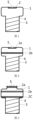
- the device includes a shell 1, a single layer filtering membrane 2 and a connecting port 3.
- the connecting port 3 is internally provided with an internal thread 4 adapted to an external thread of a positive-pressure connector 6, an air pressure balance hole 5 is disposed at the top of the shell 1, and the single layer filtering membrane 2 is clinging to the bottom of the air pressure balance hole 5.
- the pore diameter of the filtering membrane is from nanometer to micrometer
- the filtering membrane includes, but is not limited to, a polyethersulfone membrane, a cellulose filter membrane, a nuclear track membrane, an ion-exchange membrane, a nylon membrane, a polytetrafluoroethylene membrane, a polyvinylidene fluoride membrane, or a polypropylene membrane.
- the shape of the shell 1 includes, but is not limited to, a cylindrical shape, a spherical shape, an ellipsoidal shape, a rectangular shape, a gourd shape, an upper convex lower flat shape, an upper flat lower convex shape, an upper large lower small shape, or an upper small lower large shape.
- the pore diameter of the air pressure balance hole 5 is from nanometer to millimeter, and the shape of the air pressure balance hole 5 includes, but is not limited to, a circle, an ellipse, a square, a rectangle, or a triangle.
- the device according to this embodiment is provided with the adapted connecting port 3, which can be connected to the positive-pressure connector 6.
- the present disclosure further provides a method based on the device according to this embodiment, a filtering membrane is disposed between an air pressure balance hole and a connecting port, and microorganisms, bacteria, viruses, dusts and particulate pollution sources are isolated and filtered through the filtering membrane.
- the inner cavity of the shell is in communication with the outside through the air pressure balance hole to achieve air exchange, and ensure that the device is in a positive-pressure state.
- the device includes a shell 1, a connecting port 3 fixedly connected to the shell 1 and used for connecting to the positive-pressure connector 6, an air pressure balance hole 5 disposed opposite to the connecting port 3 and provided on the shell 1, and a filtering membrane disposed between the air pressure balance hole 5 and the connecting port 3.
- the air pressure balance hole 5 is at the top of the shell 1, and the filtering membrane includes a primary filtering membrane 2a clinging to the bottom of the air pressure balance hole 5 and a second filtering membrane 2b directly below the primary filtering membrane 2a, and the connecting port 3 is internally provided with an internal thread 4 adapted to an external thread of the positive-pressure connector 6.
- the device includes a shell 1, a connecting port 3 fixedly connected to the shell 1 and used for connecting to the positive-pressure connector 6, an air pressure balance hole 5 disposed opposite to the connecting port 3 and provided on the shell 1, and a filtering membrane disposed between the air pressure balance hole 5 and the connecting port 3.
- the top of the shell 1 is provided with an upward convex part, and the air pressure balance hole 5 is at the convex part.
- the filtering membrane includes a primary filtering membrane 2a clinging to the bottom of the air pressure balance hole 5, and a second filtering membrane 2b and a third filtering membrane 2c sequentially disposed from the top to the bottom below the primary filtering membrane 2a.
- the third filtering membrane 2c is disposed clinging to the top of the connecting port 3, and the connecting port 3 is internally provided with an internal thread 4 adapted to an external thread of the positive-pressure connector 6.
- the device includes a shell 1, a connecting port 3 fixedly connected to the shell 1 and used for connecting to the positive-pressure connector 6, an air pressure balance hole 5 disposed opposite to the connecting port 3 and provided on the shell 1, and a filtering membrane disposed between the air pressure balance hole 5 and the connecting port 3.
- the top of the shell 1 is provided with a downward groove, the air pressure balance hole 5 is at the groove, the interior of the shell 1 is provided with an upward convex platform, the platform is provided with at least one air vent, and the air vent can conduct air in upper and lower cavities.
- the shape of the air vent includes, but is not limited to, a circle, an ellipse, a square, a rectangle, or a triangle.
- the filtering membrane includes a primary filtering membrane 2a clinging to the bottom of the air pressure balance hole 5 and a second filtering membrane 2b laid on the platform, and the connecting port 3 is internally provided with an internal thread 4 adapted to an external thread of the positive-pressure connector 6.
- the device includes a shell 1, a connecting port 3 fixedly connected to the shell 1 and used for connecting to the positive-pressure connector 6, an air pressure balance hole 5 provided on the shell 1, and a filtering membrane disposed between the air pressure balance hole 5 and the connecting port 3.
- the air pressure balance hole 5 is at the side wall of the shell 1, the interior of the shell 1 is provided with an upward convex platform, the platform is provided with at least one air vent, and the air vent can conduct air in upper and lower cavities.
- the shape of the air vent includes, but is not limited to, a circle, an ellipse, a square, a rectangle, or a triangle.
- the filtering membrane includes a primary filtering membrane 2a laid on the platform and a second filtering membrane 2b disposed between the primary filtering membrane 2a and the connecting port 3, and the connecting port 3 is internally provided with an internal thread 4 adapted to the external thread of the positive-pressure connector 6.
- the device includes a shell 1, a connecting port 3 fixedly connected to the shell 1 and used for connecting to the positive-pressure connector 6, an air pressure balance hole 5 disposed opposite to the connecting port 3 and provided on the shell 1, and a filtering membrane disposed between the air pressure balance hole 5 and the connecting port 3.
- the air pressure balance hole 5 is at the top of the shell 1
- the filtering membrane includes a primary filtering membrane 2a clinging to the bottom of the air pressure balance hole 5 and a second filtering membrane 2b clinging to the top of the connecting port 3, and the connecting port 3 is internally provided with an internal thread 4 adapted to an external thread of the positive-pressure connector 6.
- an internal thread 4 of a device according to this embodiment is connected to an external thread of a positive-pressure connector 6.
- the device After an infusion, the device is installed at the interface end of the positive-pressure connector 6 through the connecting port 3, to prevent the interface of the positive-pressure connector 6 from being contaminated by potential contaminants due to long-time exposure to the air.
- the anticontamination device sleeved on the positive-pressure connector 6 is detached, and then conventional infusion can be performed. Since the air pressure balance hole 5 is on the shell 1 of the device, the positive pressure effect can be maintained for a long time. Since the rejection coefficient of the filtering membrane is high, microorganisms, dusts, particulate matter and the like can be effectively filtered and cannot contaminate the interface of the positive-pressure connector 6. Due to the design of the multilayer filtering membrane, deposition of moisture in the air in the shell 1 can be avoided. Since the interface of the positive-pressure connector 6 is not exposed to the air, nursing staff do not need to wipe to disinfect the interface of the positive-pressure connector with alcohol, thereby improving the working efficiency of medical staff.
Landscapes
- Health & Medical Sciences (AREA)
- Heart & Thoracic Surgery (AREA)
- Engineering & Computer Science (AREA)
- Life Sciences & Earth Sciences (AREA)
- Public Health (AREA)
- Veterinary Medicine (AREA)
- Anesthesiology (AREA)
- Biomedical Technology (AREA)
- Animal Behavior & Ethology (AREA)
- General Health & Medical Sciences (AREA)
- Hematology (AREA)
- Chemical & Material Sciences (AREA)
- Chemical Kinetics & Catalysis (AREA)
- Vascular Medicine (AREA)
- Pulmonology (AREA)
- Water Supply & Treatment (AREA)
- Infusion, Injection, And Reservoir Apparatuses (AREA)
- Separation Using Semi-Permeable Membranes (AREA)
Claims (9)
- Vorrichtung zur Verhinderung der Kontamination eines Überdruckverbinders einer Verweilnadel während des Verweilens von Infusionsintervallen, umfassend:ein Gehäuse (1);eine Verbindungsbuchse (3), die fest mit einem ersten Ende des Gehäuses (1) verbunden ist und zum Verbinden mit dem Überdruckverbinder dient;ein Luftdruckausgleichsloch (5), das an einem zweiten Ende des Gehäuses (1) angeordnet ist und das dem ersten Ende, an dem die Verbindungsbuchse (3) angeschlossen ist, gegenüberliegt; undeine Filtermembran (2, 2a, 2b, 2c), die zwischen der Luftdruckausgleichsöffnung (5) und der Verbindungsbuchse (3) angeordnet ist, dadurch gekennzeichnet, dassder Überdruckverbinder Luft mit der Außenseite durch das Luftdruckausgleichsloch (5) austauscht, um einen Überdruckzustand zu erreichen;ein innerer Hohlraum des Gehäuses mit der Außenseite durch die Luftdruckausgleichsöffnung (5) in Verbindung steht;der Porendurchmesser der Filtermembran (2, 2a, 2b, 2c) 0,02-2 µm beträgt und die Filtermembran eine Polyethersulfon-Membran, eine Zellulosefiltermembran, eine Kernspurmembran, eine Ionenaustauschmembran, eine Nylonmembran, eine Polytetrafluorethylen-Membran, eine Polyvinylidenfluorid-Membran oder eine Polypropylen-Membran umfasst, ohne jedoch darauf beschränkt zu sein.
- Vorrichtung zur Verhinderung der Kontamination eines Überdruckverbinders einer Verweilnadel nach Anspruch 1, wobeiein oder mehrere Luftdruckausgleichslöcher (5) vorgesehen sind; undeine oder mehrere Filtermembranen (2, 2a, 2b, 2c) vorgesehen sind.
- Vorrichtung zur Verhinderung der Kontamination eines Überdruckverbinders einer Verweilnadel nach Anspruch 2, wobeisich das Luftdruckausgleichsloch (5) am ersten Ende des Gehäuses (1) befindet;die Filtermembran (2) eine einlagige Filtermembran ist und an einer Seite des Luftdruckausgleichslochs (5) anhaftet, die der Verbindungsbuchse (3) am nächsten ist; unddie Verbindungsbuchse (3) innen mit einem Innengewinde (4) versehen ist, das an ein Außengewinde des Überdruckverbinders angepasst ist.
- Vorrichtung zur Verhinderung der Kontamination eines Überdruckverbinders einer Verweilnadel nach Anspruch 2, wobeisich das Luftdruckausgleichsloch (5) am ersten Ende des Gehäuses befindet;die Filtermembran (2a, 2b) umfassteine primäre Filtermembran (2a), die an einer Seite des Luftdruckausgleichslochs (5) anhaftet, die der Verbindungsbuchse (3) am nächsten liegt; undeine zweite Filtermembran (2b) zwischen der primären Filtermembran (2a) und der Verbindungsbuchse (3); unddie Verbindungsbuchse (3) innen mit einem Innengewinde (4) versehen ist, das an ein Außengewinde des Überdruckverbinders angepasst ist.
- Vorrichtung zur Verhinderung der Kontamination eines Überdruckverbinders einer Verweilnadel nach Anspruch 2, wobeidas erste Ende des Gehäuses (1) mit einem vorspringenden konvexen Teil versehen ist;sich das Luftdruckausgleichsloch (5) an dem konvexen Teil befindet;die Filtermembran (2a, 2b, 2c) umfassteine primäre Filtermembran (2a), die an einer Seite des Luftdruckausgleichslochs (5) anhaftet, die der Verbindungsbuchse (3) am nächsten liegt; undeine zweite Filtermembran (2b) und eine dritte Filtermembran (2c), die aufeinanderfolgend zwischen der primären Filtermembran (2a) und der Verbindungsbuchse (3) vorgesehen sind, wobeidie dritte Filtermembran (2c) an einer Seite der Verbindungsbuchse (3) anhaftet, die der primären Filtermembran (2a) am nächsten liegt; unddie Verbindungsbuchse (3) innen mit einem Innengewinde (4) versehen ist, das an ein Außengewinde des Überdruckverbinders angepasst ist.
- Vorrichtung zur Verhinderung der Kontamination eines Überdruckverbinders einer Verweilnadel nach Anspruch 2, wobeidas erste Ende des Gehäuses (1) mit einer vertieften Rille versehen ist;sich das Luftdruckausgleichsloch (2a) in der Rille befindet;das Innere des Gehäuses (1) mit einer konvexen Plattform versehen ist, die zum ersten Ende hin ausgerichtet ist;die Filtermembran umfassteine primäre Filtermembran (2a), die an einer Seite des Luftdruckausgleichslochs anhaftet (5), die der Verbindungsbuchse (3) am nächsten liegt; undeine zweite Filtermembran (2b), die auf der Plattform liegt; unddie Verbindungsbuchse (3) innen mit einem Innengewinde (4) versehen ist, das an ein Außengewinde des Überdruckverbinders angepasst ist.
- Vorrichtung zur Verhinderung der Kontamination eines Überdruckverbinders einer Verweilnadel nach Anspruch 2, wobeisich das Luftdruckausgleichsloch (5) an einer Seitenwand des Gehäuses (5) befindet;das Innere des Gehäuses (1) mit einer konvexen Plattform versehen ist, die zum ersten Ende hin ausgerichtet ist;die Filtermembran umfassteine primäre Filtermembran (2a), die auf der Plattform liegt, undeine zweite Filtermembran (2b), die zwischen der primären Filtermembran (2a) und der Verbindungsbuchse (3) angeordnet ist; unddie Verbindungsbuchse (3) innen mit einem Innengewinde (4) versehen ist, das an ein Außengewinde des Überdruckverbinders angepasst ist.
- Vorrichtung zur Verhinderung der Kontamination eines Überdruckverbinders einer Verweilnadel nach Anspruch 2, wobeisich das Luftdruckausgleichsloch (5) am ersten Ende des Gehäuses (1) befindet;die Filtermembran umfassteine primäre Filtermembran (2a), die an einer Seite des Luftdruckausgleichslochs (5) anhaftet, die der Verbindungsbuchse (3) am nächsten liegt; undeine zweite Filtermembran (2b), die an einer Seite der Verbindungsbuchse (3) anhaftet, die der primären Filtermembran (2a) am nächsten liegt; unddie Verbindungsbuchse (3) innen mit einem Innengewinde (4) versehen ist, das an ein Außengewinde des Überdruckverbinders angepasst ist.
- Vorrichtung zur Verhinderung der Kontamination eines Überdruckverbinders einer Verweilnadel nach einem der Ansprüche 1 bis 8, wobeidie Form des Gehäuses (1) eine zylindrische Form, eine kugelförmige Form, eine ellipsoide Form, eine rechteckige Form, eine Kürbisform, eine oben konvexe und unten flache Form, eine oben flache und unten konvexe Form, eine oben große und unten kleine Form oder eine oben kleine und unten große Form umfasst, ohne jedoch darauf beschränkt zu sein;der Porendurchmesser des Luftdruckausgleichslochs (5) zwischen einem Nanometer und einem Millimeter beträgt und die Form des Luftdruckausgleichslochs (5) einen Kreis, eine Ellipse, ein Quadrat, ein Rechteck oder ein Dreieck umfasst, ohne jedoch darauf beschränkt sein.
Applications Claiming Priority (2)
| Application Number | Priority Date | Filing Date | Title |
|---|---|---|---|
| CN201611227156.9A CN107754049A (zh) | 2016-12-27 | 2016-12-27 | 防止留置针正压接头污染的装置及基于该装置的方法 |
| PCT/CN2017/099018 WO2018120873A1 (zh) | 2016-12-27 | 2017-08-25 | 防止留置针正压接头污染的装置及基于该装置的方法 |
Publications (4)
| Publication Number | Publication Date |
|---|---|
| EP3563893A1 EP3563893A1 (de) | 2019-11-06 |
| EP3563893A4 EP3563893A4 (de) | 2020-09-09 |
| EP3563893B1 true EP3563893B1 (de) | 2023-08-23 |
| EP3563893C0 EP3563893C0 (de) | 2023-08-23 |
Family
ID=61264823
Family Applications (1)
| Application Number | Title | Priority Date | Filing Date |
|---|---|---|---|
| EP17886627.3A Active EP3563893B1 (de) | 2016-12-27 | 2017-08-25 | Vorrichtung zur verhinderung der kontamination eines überdruckverbinders einer verweilnadel und darauf basierendes verfahren |
Country Status (4)
| Country | Link |
|---|---|
| US (1) | US11697014B2 (de) |
| EP (1) | EP3563893B1 (de) |
| CN (1) | CN107754049A (de) |
| WO (1) | WO2018120873A1 (de) |
Families Citing this family (5)
| Publication number | Priority date | Publication date | Assignee | Title |
|---|---|---|---|---|
| CN111166603A (zh) * | 2020-01-03 | 2020-05-19 | 北京大学深圳医院 | 用于心脏介入手术中的手托板 |
| EP4140529A4 (de) * | 2020-04-23 | 2024-05-29 | Otsuka Techno Corporation | Harnkatheterkappe |
| US20210338991A1 (en) * | 2020-04-29 | 2021-11-04 | Medtronic Xomed, Inc. | System and Method for a Covering |
| CN111672007B (zh) * | 2020-05-15 | 2022-09-16 | 山东柏新医疗制品有限公司 | 一种防感染的中心静脉导管 |
| CN114132032B (zh) * | 2021-11-24 | 2024-03-08 | 西南林业大学 | 一种有吸附性的空气过滤膜及其制备方法 |
Family Cites Families (16)
| Publication number | Priority date | Publication date | Assignee | Title |
|---|---|---|---|---|
| DE3147499A1 (de) * | 1981-12-01 | 1983-06-09 | B. Braun Melsungen Ag, 3508 Melsungen | "entlueftungseinrichtung fuer ein medizinisches fluessigkeitssystem" |
| DE8625003U1 (de) * | 1986-09-18 | 1986-11-06 | B. Braun Melsungen Ag, 3508 Melsungen | Entlüftungsventil |
| EP2366424A4 (de) * | 2008-11-05 | 2012-12-26 | Jms Co Ltd | Atmungsaktive struktur und verfahren zur bildung einer atmungsaktiven struktur |
| CN201361314Y (zh) * | 2009-02-24 | 2009-12-16 | 佛山市爱迪医疗器械有限公司 | 一种可自动排气的留置针 |
| US8383044B2 (en) * | 2009-07-09 | 2013-02-26 | Becton, Dickinson And Company | Blood sampling device |
| CN201609520U (zh) * | 2010-01-11 | 2010-10-20 | 吴林元 | 一次性使用阻菌帽 |
| CN202961357U (zh) * | 2012-11-13 | 2013-06-05 | 邵聪文 | 一种新型留置针 |
| CN104288874B (zh) * | 2013-07-19 | 2017-09-26 | 广东龙心医疗器械有限公司 | 一次性使用自动排气止液输液器和方法 |
| CN203694250U (zh) * | 2014-01-09 | 2014-07-09 | 江苏苏云医疗器材有限公司 | 一种新型自排气式留置针 |
| CN203694241U (zh) * | 2014-01-20 | 2014-07-09 | 山东威高集团医用高分子制品股份有限公司 | 一种密闭式输液接头 |
| CN103990226A (zh) * | 2014-06-10 | 2014-08-20 | 倪新华 | 排气阻菌帽 |
| CN204246597U (zh) * | 2014-10-27 | 2015-04-08 | 张玉龙 | 一次性过滤留置针 |
| CN204411414U (zh) * | 2015-01-17 | 2015-06-24 | 陈伟权 | 一种静脉留置针用防血拴安全盖 |
| CN104606739A (zh) * | 2015-01-17 | 2015-05-13 | 陈伟权 | 一种静脉留置针用防血拴安全盖及其使用方法 |
| CN104857588B (zh) * | 2015-06-03 | 2020-03-17 | 四川南格尔生物科技有限公司 | 一种安全型袋式输液器 |
| CN114870166B (zh) * | 2016-08-31 | 2023-06-20 | 广东龙心医疗器械有限公司 | 排气接头 |
-
2016
- 2016-12-27 CN CN201611227156.9A patent/CN107754049A/zh active Pending
-
2017
- 2017-08-25 US US16/473,626 patent/US11697014B2/en active Active
- 2017-08-25 WO PCT/CN2017/099018 patent/WO2018120873A1/zh not_active Ceased
- 2017-08-25 EP EP17886627.3A patent/EP3563893B1/de active Active
Also Published As
| Publication number | Publication date |
|---|---|
| EP3563893A1 (de) | 2019-11-06 |
| CN107754049A (zh) | 2018-03-06 |
| WO2018120873A1 (zh) | 2018-07-05 |
| US20190329173A1 (en) | 2019-10-31 |
| EP3563893C0 (de) | 2023-08-23 |
| US11697014B2 (en) | 2023-07-11 |
| EP3563893A4 (de) | 2020-09-09 |
Similar Documents
| Publication | Publication Date | Title |
|---|---|---|
| US11697014B2 (en) | Device for preventing contamination of positive-pressure connector of indwelling needle and method based on same | |
| CA2940164C (en) | Connector with filter | |
| EP3912671B1 (de) | Desinfektionskappe zur desinfektion eines luer-steckerendes einer infusionstherapievorrichtung | |
| US7780794B2 (en) | Medical implement cleaning device | |
| CA1134698A (en) | Sterile air vent | |
| US20210316130A1 (en) | Capping and cleansing devices for needlefree vascular access connectors | |
| US11433228B2 (en) | Single use caps and covers for vascular access devices, and kits and methods for using the same | |
| US20210346672A1 (en) | Capping and cleansing devices for threaded vascular access connectors | |
| JPH0376948B2 (de) | ||
| AU2013278009A1 (en) | Antimicrobial devices for use with medical devices and related assemblies and methods | |
| CN222426725U (zh) | 一种用于医疗装置的消毒帽 | |
| JP2025156574A (ja) | 消毒キャップ | |
| EP4135827A1 (de) | Desinfektionskappe | |
| CN205549224U (zh) | 一种消毒帽 | |
| US10576261B2 (en) | Device male port cleaner | |
| CN207785593U (zh) | 一种医用留置针正压接头防污装置 | |
| JP2024037783A (ja) | 無針血管アクセスコネクタのための密封及びクリーンシング装置 | |
| WO2014077906A1 (en) | Antimicrobial devices for use with medical devices, medical device assemblies and related methods | |
| CN107198822B (zh) | 一种消毒帽 | |
| US20190076327A1 (en) | Devices and systems with an internal displacement mechanism for contaminant-free engagement of medical vessels and devices | |
| AU2014101522A4 (en) | Antimicrobial devices for use with medical devices and related assemblies and methods |
Legal Events
| Date | Code | Title | Description |
|---|---|---|---|
| STAA | Information on the status of an ep patent application or granted ep patent |
Free format text: STATUS: THE INTERNATIONAL PUBLICATION HAS BEEN MADE |
|
| PUAI | Public reference made under article 153(3) epc to a published international application that has entered the european phase |
Free format text: ORIGINAL CODE: 0009012 |
|
| STAA | Information on the status of an ep patent application or granted ep patent |
Free format text: STATUS: REQUEST FOR EXAMINATION WAS MADE |
|
| 17P | Request for examination filed |
Effective date: 20190627 |
|
| AK | Designated contracting states |
Kind code of ref document: A1 Designated state(s): AL AT BE BG CH CY CZ DE DK EE ES FI FR GB GR HR HU IE IS IT LI LT LU LV MC MK MT NL NO PL PT RO RS SE SI SK SM TR |
|
| AX | Request for extension of the european patent |
Extension state: BA ME |
|
| DAV | Request for validation of the european patent (deleted) | ||
| DAX | Request for extension of the european patent (deleted) | ||
| A4 | Supplementary search report drawn up and despatched |
Effective date: 20200810 |
|
| RIC1 | Information provided on ipc code assigned before grant |
Ipc: A61M 39/16 20060101ALI20200804BHEP Ipc: A61M 5/165 20060101ALI20200804BHEP Ipc: B01D 69/02 20060101ALI20200804BHEP Ipc: A61M 39/20 20060101ALI20200804BHEP Ipc: B01D 61/58 20060101ALI20200804BHEP Ipc: A61M 5/158 20060101AFI20200804BHEP |
|
| RIC1 | Information provided on ipc code assigned before grant |
Ipc: B01D 69/02 20060101ALI20230329BHEP Ipc: B01D 61/58 20060101ALI20230329BHEP Ipc: A61M 39/20 20060101ALI20230329BHEP Ipc: A61M 39/16 20060101ALI20230329BHEP Ipc: A61M 5/165 20060101ALI20230329BHEP Ipc: A61M 5/158 20060101AFI20230329BHEP |
|
| GRAP | Despatch of communication of intention to grant a patent |
Free format text: ORIGINAL CODE: EPIDOSNIGR1 |
|
| STAA | Information on the status of an ep patent application or granted ep patent |
Free format text: STATUS: GRANT OF PATENT IS INTENDED |
|
| INTG | Intention to grant announced |
Effective date: 20230512 |
|
| GRAS | Grant fee paid |
Free format text: ORIGINAL CODE: EPIDOSNIGR3 |
|
| GRAA | (expected) grant |
Free format text: ORIGINAL CODE: 0009210 |
|
| STAA | Information on the status of an ep patent application or granted ep patent |
Free format text: STATUS: THE PATENT HAS BEEN GRANTED |
|
| AK | Designated contracting states |
Kind code of ref document: B1 Designated state(s): AL AT BE BG CH CY CZ DE DK EE ES FI FR GB GR HR HU IE IS IT LI LT LU LV MC MK MT NL NO PL PT RO RS SE SI SK SM TR |
|
| REG | Reference to a national code |
Ref country code: GB Ref legal event code: FG4D |
|
| REG | Reference to a national code |
Ref country code: CH Ref legal event code: EP |
|
| REG | Reference to a national code |
Ref country code: IE Ref legal event code: FG4D |
|
| REG | Reference to a national code |
Ref country code: DE Ref legal event code: R096 Ref document number: 602017073258 Country of ref document: DE |
|
| U01 | Request for unitary effect filed |
Effective date: 20230922 |
|
| U07 | Unitary effect registered |
Designated state(s): AT BE BG DE DK EE FI FR IT LT LU LV MT NL PT SE SI Effective date: 20230928 |
|
| U20 | Renewal fee for the european patent with unitary effect paid |
Year of fee payment: 7 Effective date: 20231206 |
|
| PG25 | Lapsed in a contracting state [announced via postgrant information from national office to epo] |
Ref country code: GR Free format text: LAPSE BECAUSE OF FAILURE TO SUBMIT A TRANSLATION OF THE DESCRIPTION OR TO PAY THE FEE WITHIN THE PRESCRIBED TIME-LIMIT Effective date: 20231124 |
|
| PG25 | Lapsed in a contracting state [announced via postgrant information from national office to epo] |
Ref country code: IS Free format text: LAPSE BECAUSE OF FAILURE TO SUBMIT A TRANSLATION OF THE DESCRIPTION OR TO PAY THE FEE WITHIN THE PRESCRIBED TIME-LIMIT Effective date: 20231223 |
|
| PG25 | Lapsed in a contracting state [announced via postgrant information from national office to epo] |
Ref country code: RS Free format text: LAPSE BECAUSE OF FAILURE TO SUBMIT A TRANSLATION OF THE DESCRIPTION OR TO PAY THE FEE WITHIN THE PRESCRIBED TIME-LIMIT Effective date: 20230823 Ref country code: NO Free format text: LAPSE BECAUSE OF FAILURE TO SUBMIT A TRANSLATION OF THE DESCRIPTION OR TO PAY THE FEE WITHIN THE PRESCRIBED TIME-LIMIT Effective date: 20231123 Ref country code: IS Free format text: LAPSE BECAUSE OF FAILURE TO SUBMIT A TRANSLATION OF THE DESCRIPTION OR TO PAY THE FEE WITHIN THE PRESCRIBED TIME-LIMIT Effective date: 20231223 Ref country code: HR Free format text: LAPSE BECAUSE OF FAILURE TO SUBMIT A TRANSLATION OF THE DESCRIPTION OR TO PAY THE FEE WITHIN THE PRESCRIBED TIME-LIMIT Effective date: 20230823 Ref country code: GR Free format text: LAPSE BECAUSE OF FAILURE TO SUBMIT A TRANSLATION OF THE DESCRIPTION OR TO PAY THE FEE WITHIN THE PRESCRIBED TIME-LIMIT Effective date: 20231124 |
|
| PG25 | Lapsed in a contracting state [announced via postgrant information from national office to epo] |
Ref country code: PL Free format text: LAPSE BECAUSE OF FAILURE TO SUBMIT A TRANSLATION OF THE DESCRIPTION OR TO PAY THE FEE WITHIN THE PRESCRIBED TIME-LIMIT Effective date: 20230823 |
|
| REG | Reference to a national code |
Ref country code: CH Ref legal event code: PL |
|
| PG25 | Lapsed in a contracting state [announced via postgrant information from national office to epo] |
Ref country code: ES Free format text: LAPSE BECAUSE OF FAILURE TO SUBMIT A TRANSLATION OF THE DESCRIPTION OR TO PAY THE FEE WITHIN THE PRESCRIBED TIME-LIMIT Effective date: 20230823 |
|
| PG25 | Lapsed in a contracting state [announced via postgrant information from national office to epo] |
Ref country code: SM Free format text: LAPSE BECAUSE OF FAILURE TO SUBMIT A TRANSLATION OF THE DESCRIPTION OR TO PAY THE FEE WITHIN THE PRESCRIBED TIME-LIMIT Effective date: 20230823 Ref country code: RO Free format text: LAPSE BECAUSE OF FAILURE TO SUBMIT A TRANSLATION OF THE DESCRIPTION OR TO PAY THE FEE WITHIN THE PRESCRIBED TIME-LIMIT Effective date: 20230823 Ref country code: ES Free format text: LAPSE BECAUSE OF FAILURE TO SUBMIT A TRANSLATION OF THE DESCRIPTION OR TO PAY THE FEE WITHIN THE PRESCRIBED TIME-LIMIT Effective date: 20230823 Ref country code: CZ Free format text: LAPSE BECAUSE OF FAILURE TO SUBMIT A TRANSLATION OF THE DESCRIPTION OR TO PAY THE FEE WITHIN THE PRESCRIBED TIME-LIMIT Effective date: 20230823 Ref country code: SK Free format text: LAPSE BECAUSE OF FAILURE TO SUBMIT A TRANSLATION OF THE DESCRIPTION OR TO PAY THE FEE WITHIN THE PRESCRIBED TIME-LIMIT Effective date: 20230823 Ref country code: CH Free format text: LAPSE BECAUSE OF NON-PAYMENT OF DUE FEES Effective date: 20230831 |
|
| REG | Reference to a national code |
Ref country code: IE Ref legal event code: MM4A |
|
| REG | Reference to a national code |
Ref country code: DE Ref legal event code: R097 Ref document number: 602017073258 Country of ref document: DE |
|
| PG25 | Lapsed in a contracting state [announced via postgrant information from national office to epo] |
Ref country code: MC Free format text: LAPSE BECAUSE OF FAILURE TO SUBMIT A TRANSLATION OF THE DESCRIPTION OR TO PAY THE FEE WITHIN THE PRESCRIBED TIME-LIMIT Effective date: 20230823 |
|
| PLBE | No opposition filed within time limit |
Free format text: ORIGINAL CODE: 0009261 |
|
| STAA | Information on the status of an ep patent application or granted ep patent |
Free format text: STATUS: NO OPPOSITION FILED WITHIN TIME LIMIT |
|
| PG25 | Lapsed in a contracting state [announced via postgrant information from national office to epo] |
Ref country code: IE Free format text: LAPSE BECAUSE OF NON-PAYMENT OF DUE FEES Effective date: 20230825 |
|
| GBPC | Gb: european patent ceased through non-payment of renewal fee |
Effective date: 20231123 |
|
| 26N | No opposition filed |
Effective date: 20240524 |
|
| PG25 | Lapsed in a contracting state [announced via postgrant information from national office to epo] |
Ref country code: IE Free format text: LAPSE BECAUSE OF NON-PAYMENT OF DUE FEES Effective date: 20230825 |
|
| U20 | Renewal fee for the european patent with unitary effect paid |
Year of fee payment: 8 Effective date: 20240827 |
|
| PG25 | Lapsed in a contracting state [announced via postgrant information from national office to epo] |
Ref country code: GB Free format text: LAPSE BECAUSE OF NON-PAYMENT OF DUE FEES Effective date: 20231123 |
|
| PG25 | Lapsed in a contracting state [announced via postgrant information from national office to epo] |
Ref country code: GB Free format text: LAPSE BECAUSE OF NON-PAYMENT OF DUE FEES Effective date: 20231123 |
|
| U1N | Appointed representative for the unitary patent procedure changed after the registration of the unitary effect |
Representative=s name: BIRD & BIRD SOCIETA TRA AVVOCATI S.R.L.; IT |
|
| PG25 | Lapsed in a contracting state [announced via postgrant information from national office to epo] |
Ref country code: CY Free format text: LAPSE BECAUSE OF FAILURE TO SUBMIT A TRANSLATION OF THE DESCRIPTION OR TO PAY THE FEE WITHIN THE PRESCRIBED TIME-LIMIT; INVALID AB INITIO Effective date: 20170825 |
|
| PG25 | Lapsed in a contracting state [announced via postgrant information from national office to epo] |
Ref country code: HU Free format text: LAPSE BECAUSE OF FAILURE TO SUBMIT A TRANSLATION OF THE DESCRIPTION OR TO PAY THE FEE WITHIN THE PRESCRIBED TIME-LIMIT; INVALID AB INITIO Effective date: 20170825 |
|
| U20 | Renewal fee for the european patent with unitary effect paid |
Year of fee payment: 9 Effective date: 20250826 |
|
| PG25 | Lapsed in a contracting state [announced via postgrant information from national office to epo] |
Ref country code: TR Free format text: LAPSE BECAUSE OF FAILURE TO SUBMIT A TRANSLATION OF THE DESCRIPTION OR TO PAY THE FEE WITHIN THE PRESCRIBED TIME-LIMIT Effective date: 20230823 |