EP3563802B1 - Luminal stent - Google Patents
Luminal stent Download PDFInfo
- Publication number
- EP3563802B1 EP3563802B1 EP17889447.3A EP17889447A EP3563802B1 EP 3563802 B1 EP3563802 B1 EP 3563802B1 EP 17889447 A EP17889447 A EP 17889447A EP 3563802 B1 EP3563802 B1 EP 3563802B1
- Authority
- EP
- European Patent Office
- Prior art keywords
- tube body
- diameter
- luminal stent
- leakage structure
- coating membrane
- Prior art date
- Legal status (The legal status is an assumption and is not a legal conclusion. Google has not performed a legal analysis and makes no representation as to the accuracy of the status listed.)
- Active
Links
- 239000012528 membrane Substances 0.000 claims description 48
- 239000011248 coating agent Substances 0.000 claims description 47
- 238000000576 coating method Methods 0.000 claims description 47
- 230000006835 compression Effects 0.000 claims description 41
- 238000007906 compression Methods 0.000 claims description 41
- 229910052751 metal Inorganic materials 0.000 claims description 10
- 239000002184 metal Substances 0.000 claims description 10
- 230000004323 axial length Effects 0.000 claims description 5
- 238000010586 diagram Methods 0.000 description 12
- 239000008280 blood Substances 0.000 description 6
- 210000004369 blood Anatomy 0.000 description 6
- 238000007789 sealing Methods 0.000 description 6
- 208000001750 Endoleak Diseases 0.000 description 5
- 206010064396 Stent-graft endoleak Diseases 0.000 description 5
- 230000017531 blood circulation Effects 0.000 description 5
- 210000004204 blood vessel Anatomy 0.000 description 5
- 230000008859 change Effects 0.000 description 4
- 230000000694 effects Effects 0.000 description 4
- 238000000034 method Methods 0.000 description 4
- 230000008569 process Effects 0.000 description 4
- 238000006073 displacement reaction Methods 0.000 description 3
- 238000005516 engineering process Methods 0.000 description 3
- 239000000463 material Substances 0.000 description 3
- 238000002513 implantation Methods 0.000 description 2
- 229910001285 shape-memory alloy Inorganic materials 0.000 description 2
- 230000009466 transformation Effects 0.000 description 2
- 238000000844 transformation Methods 0.000 description 2
- 229920004933 Terylene® Polymers 0.000 description 1
- 229910001069 Ti alloy Inorganic materials 0.000 description 1
- 230000009471 action Effects 0.000 description 1
- 239000000956 alloy Substances 0.000 description 1
- 238000004873 anchoring Methods 0.000 description 1
- 230000036770 blood supply Effects 0.000 description 1
- 230000003247 decreasing effect Effects 0.000 description 1
- 230000002526 effect on cardiovascular system Effects 0.000 description 1
- 229910001000 nickel titanium Inorganic materials 0.000 description 1
- 230000002093 peripheral effect Effects 0.000 description 1
- 239000005020 polyethylene terephthalate Substances 0.000 description 1
- 229920000642 polymer Polymers 0.000 description 1
- -1 polytetrafluoroethylene Polymers 0.000 description 1
- 229920001343 polytetrafluoroethylene Polymers 0.000 description 1
- 239000004810 polytetrafluoroethylene Substances 0.000 description 1
- 239000010935 stainless steel Substances 0.000 description 1
- 229910001220 stainless steel Inorganic materials 0.000 description 1
- 239000000126 substance Substances 0.000 description 1
- 238000010998 test method Methods 0.000 description 1
- 238000002560 therapeutic procedure Methods 0.000 description 1
- 239000010409 thin film Substances 0.000 description 1
- 230000002537 thrombolytic effect Effects 0.000 description 1
Images

Classifications
-
- A—HUMAN NECESSITIES
- A61—MEDICAL OR VETERINARY SCIENCE; HYGIENE
- A61F—FILTERS IMPLANTABLE INTO BLOOD VESSELS; PROSTHESES; DEVICES PROVIDING PATENCY TO, OR PREVENTING COLLAPSING OF, TUBULAR STRUCTURES OF THE BODY, e.g. STENTS; ORTHOPAEDIC, NURSING OR CONTRACEPTIVE DEVICES; FOMENTATION; TREATMENT OR PROTECTION OF EYES OR EARS; BANDAGES, DRESSINGS OR ABSORBENT PADS; FIRST-AID KITS
- A61F2/00—Filters implantable into blood vessels; Prostheses, i.e. artificial substitutes or replacements for parts of the body; Appliances for connecting them with the body; Devices providing patency to, or preventing collapsing of, tubular structures of the body, e.g. stents
- A61F2/02—Prostheses implantable into the body
- A61F2/04—Hollow or tubular parts of organs, e.g. bladders, tracheae, bronchi or bile ducts
- A61F2/06—Blood vessels
- A61F2/07—Stent-grafts
-
- A—HUMAN NECESSITIES
- A61—MEDICAL OR VETERINARY SCIENCE; HYGIENE
- A61F—FILTERS IMPLANTABLE INTO BLOOD VESSELS; PROSTHESES; DEVICES PROVIDING PATENCY TO, OR PREVENTING COLLAPSING OF, TUBULAR STRUCTURES OF THE BODY, e.g. STENTS; ORTHOPAEDIC, NURSING OR CONTRACEPTIVE DEVICES; FOMENTATION; TREATMENT OR PROTECTION OF EYES OR EARS; BANDAGES, DRESSINGS OR ABSORBENT PADS; FIRST-AID KITS
- A61F2/00—Filters implantable into blood vessels; Prostheses, i.e. artificial substitutes or replacements for parts of the body; Appliances for connecting them with the body; Devices providing patency to, or preventing collapsing of, tubular structures of the body, e.g. stents
- A61F2/82—Devices providing patency to, or preventing collapsing of, tubular structures of the body, e.g. stents
- A61F2/86—Stents in a form characterised by the wire-like elements; Stents in the form characterised by a net-like or mesh-like structure
- A61F2/89—Stents in a form characterised by the wire-like elements; Stents in the form characterised by a net-like or mesh-like structure the wire-like elements comprising two or more adjacent rings flexibly connected by separate members
-
- A—HUMAN NECESSITIES
- A61—MEDICAL OR VETERINARY SCIENCE; HYGIENE
- A61F—FILTERS IMPLANTABLE INTO BLOOD VESSELS; PROSTHESES; DEVICES PROVIDING PATENCY TO, OR PREVENTING COLLAPSING OF, TUBULAR STRUCTURES OF THE BODY, e.g. STENTS; ORTHOPAEDIC, NURSING OR CONTRACEPTIVE DEVICES; FOMENTATION; TREATMENT OR PROTECTION OF EYES OR EARS; BANDAGES, DRESSINGS OR ABSORBENT PADS; FIRST-AID KITS
- A61F2/00—Filters implantable into blood vessels; Prostheses, i.e. artificial substitutes or replacements for parts of the body; Appliances for connecting them with the body; Devices providing patency to, or preventing collapsing of, tubular structures of the body, e.g. stents
- A61F2/95—Instruments specially adapted for placement or removal of stents or stent-grafts
- A61F2/962—Instruments specially adapted for placement or removal of stents or stent-grafts having an outer sleeve
-
- A—HUMAN NECESSITIES
- A61—MEDICAL OR VETERINARY SCIENCE; HYGIENE
- A61F—FILTERS IMPLANTABLE INTO BLOOD VESSELS; PROSTHESES; DEVICES PROVIDING PATENCY TO, OR PREVENTING COLLAPSING OF, TUBULAR STRUCTURES OF THE BODY, e.g. STENTS; ORTHOPAEDIC, NURSING OR CONTRACEPTIVE DEVICES; FOMENTATION; TREATMENT OR PROTECTION OF EYES OR EARS; BANDAGES, DRESSINGS OR ABSORBENT PADS; FIRST-AID KITS
- A61F2/00—Filters implantable into blood vessels; Prostheses, i.e. artificial substitutes or replacements for parts of the body; Appliances for connecting them with the body; Devices providing patency to, or preventing collapsing of, tubular structures of the body, e.g. stents
- A61F2/02—Prostheses implantable into the body
- A61F2/04—Hollow or tubular parts of organs, e.g. bladders, tracheae, bronchi or bile ducts
- A61F2/06—Blood vessels
- A61F2002/061—Blood vessels provided with means for allowing access to secondary lumens
-
- A—HUMAN NECESSITIES
- A61—MEDICAL OR VETERINARY SCIENCE; HYGIENE
- A61F—FILTERS IMPLANTABLE INTO BLOOD VESSELS; PROSTHESES; DEVICES PROVIDING PATENCY TO, OR PREVENTING COLLAPSING OF, TUBULAR STRUCTURES OF THE BODY, e.g. STENTS; ORTHOPAEDIC, NURSING OR CONTRACEPTIVE DEVICES; FOMENTATION; TREATMENT OR PROTECTION OF EYES OR EARS; BANDAGES, DRESSINGS OR ABSORBENT PADS; FIRST-AID KITS
- A61F2/00—Filters implantable into blood vessels; Prostheses, i.e. artificial substitutes or replacements for parts of the body; Appliances for connecting them with the body; Devices providing patency to, or preventing collapsing of, tubular structures of the body, e.g. stents
- A61F2/02—Prostheses implantable into the body
- A61F2/04—Hollow or tubular parts of organs, e.g. bladders, tracheae, bronchi or bile ducts
- A61F2/06—Blood vessels
- A61F2/07—Stent-grafts
- A61F2002/077—Stent-grafts having means to fill the space between stent-graft and aneurysm wall, e.g. a sleeve
-
- A—HUMAN NECESSITIES
- A61—MEDICAL OR VETERINARY SCIENCE; HYGIENE
- A61F—FILTERS IMPLANTABLE INTO BLOOD VESSELS; PROSTHESES; DEVICES PROVIDING PATENCY TO, OR PREVENTING COLLAPSING OF, TUBULAR STRUCTURES OF THE BODY, e.g. STENTS; ORTHOPAEDIC, NURSING OR CONTRACEPTIVE DEVICES; FOMENTATION; TREATMENT OR PROTECTION OF EYES OR EARS; BANDAGES, DRESSINGS OR ABSORBENT PADS; FIRST-AID KITS
- A61F2250/00—Special features of prostheses classified in groups A61F2/00 - A61F2/26 or A61F2/82 or A61F9/00 or A61F11/00 or subgroups thereof
- A61F2250/0014—Special features of prostheses classified in groups A61F2/00 - A61F2/26 or A61F2/82 or A61F9/00 or A61F11/00 or subgroups thereof having different values of a given property or geometrical feature, e.g. mechanical property or material property, at different locations within the same prosthesis
- A61F2250/0018—Special features of prostheses classified in groups A61F2/00 - A61F2/26 or A61F2/82 or A61F9/00 or A61F11/00 or subgroups thereof having different values of a given property or geometrical feature, e.g. mechanical property or material property, at different locations within the same prosthesis differing in elasticity, stiffness or compressibility
-
- A—HUMAN NECESSITIES
- A61—MEDICAL OR VETERINARY SCIENCE; HYGIENE
- A61F—FILTERS IMPLANTABLE INTO BLOOD VESSELS; PROSTHESES; DEVICES PROVIDING PATENCY TO, OR PREVENTING COLLAPSING OF, TUBULAR STRUCTURES OF THE BODY, e.g. STENTS; ORTHOPAEDIC, NURSING OR CONTRACEPTIVE DEVICES; FOMENTATION; TREATMENT OR PROTECTION OF EYES OR EARS; BANDAGES, DRESSINGS OR ABSORBENT PADS; FIRST-AID KITS
- A61F2250/00—Special features of prostheses classified in groups A61F2/00 - A61F2/26 or A61F2/82 or A61F9/00 or A61F11/00 or subgroups thereof
- A61F2250/0014—Special features of prostheses classified in groups A61F2/00 - A61F2/26 or A61F2/82 or A61F9/00 or A61F11/00 or subgroups thereof having different values of a given property or geometrical feature, e.g. mechanical property or material property, at different locations within the same prosthesis
- A61F2250/0039—Special features of prostheses classified in groups A61F2/00 - A61F2/26 or A61F2/82 or A61F9/00 or A61F11/00 or subgroups thereof having different values of a given property or geometrical feature, e.g. mechanical property or material property, at different locations within the same prosthesis differing in diameter
-
- A—HUMAN NECESSITIES
- A61—MEDICAL OR VETERINARY SCIENCE; HYGIENE
- A61F—FILTERS IMPLANTABLE INTO BLOOD VESSELS; PROSTHESES; DEVICES PROVIDING PATENCY TO, OR PREVENTING COLLAPSING OF, TUBULAR STRUCTURES OF THE BODY, e.g. STENTS; ORTHOPAEDIC, NURSING OR CONTRACEPTIVE DEVICES; FOMENTATION; TREATMENT OR PROTECTION OF EYES OR EARS; BANDAGES, DRESSINGS OR ABSORBENT PADS; FIRST-AID KITS
- A61F2250/00—Special features of prostheses classified in groups A61F2/00 - A61F2/26 or A61F2/82 or A61F9/00 or A61F11/00 or subgroups thereof
- A61F2250/0058—Additional features; Implant or prostheses properties not otherwise provided for
- A61F2250/0069—Sealing means
Definitions
- the present application relates to a cardiovascular medical device, and more particularly relates to a luminal stent.
- CN 105 496 603 A discloses a stent-graft comprising a first body and a second body which is arranged as a sheath outside the first body.
- a branch stent 2 having an anti-leakage structure such as a skirt, is generally used, and the anti-leakage structure is used to enhance the sealing effect.
- the branch stent 2 having a skirt 3 is correspondingly required to be delivered by a sheath having a relatively large diameter D.
- a part 21 that is covered by the skirt 3 of the branch stent 2 and assembled into the sheath 4 would be pressed more closely onto a sheath core by the sheath, but a part 22 that is not covered by the skirt 3 would expand by itself to squeeze the sheath core 5 slightly and even form a gap from the sheath core 5.
- the part 22 not covered by the skirt 3 and the sheath core 5 may slide relative to each other, thereby leading to the displacement of the stent.
- the present application provides a luminal stent which adapts to a relatively thin sheath and does not move during the release process.
- a luminal stent having a tube body which can be compressed and expanded in a radial direction, and an anti-leakage structure connected with the tube body.
- the tube body is divided by the anti-leakage structure into a first tube body located on one side of the anti-leakage structure and a second tube body located on the other side of the anti-leakage structure. At least part of the first tube body is encircled by the anti-leakage structure.
- the second tube body and the anti-leakage structure together with the first tube body encircled by the anti-leakage structure have maximum compression diameters when compressed to the extreme limit by a radial force distributed uniformly along a circumferential direction of the luminal stent.
- the maximum compression diameters of the anti-leakage structure and the first tube body encircled by the anti-leakage structure are approximately equal to the maximum compression diameter of the second tube body.
- the absolute value of the difference between the maximum compression diameters of the anti-leakage structure together with the part encircled by the anti-leakage structure of the first tube body and the maximum compression diameter of the second tube body is no more than 0.1 mm.
- the second tube body includes a tapered section connected with the first tube body and a straight barrel section connected with the tapered section.
- the diameter of the straight barrel section is greater than that of the part encircled by the anti-leakage structure of the first tube body.
- the difference between the diameter of the straight barrel section and the diameter of the part encircled by the anti-leakage structure of the first tube body is no more than 8 mm.
- the ratio of the difference between the diameter of the straight barrel section and the diameter of the part encircled by the anti-leakage structure of the first tube body to the diameter of the straight barrel section is 0.1 - 0.2.
- the axial length of the tapered section is 5 to 10 mm.
- the part encircled by the anti-leakage structure of the first tube body has a first diameter; and the part not encircled by the anti-leakage structure of the first tube body has a second diameter.
- the second diameter is unequal to the first diameter.
- the second diameter is greater than the first diameter.
- the anti-leakage structure includes an outer-layer coating membrane and an outer-layer radial supporting structure connected with the outer-layer coating membrane.
- the anti-leakage structure has an open end and a closed end.
- the closed end is located at a joint of the first tube body and the second tube body.
- the first tube body includes a first coating membrane and a first radial supporting structure connected with the first coating membrane.
- the second tube body includes a second coating membrane connected with the first coating membrane and a second radial supporting structure connected with the second coating membrane.
- the thickness of the first coating membrane is less than that of the second coating membrane, and/or, the metal coverage rate of the first radial supporting structure is smaller than that of the second radial supporting structure.
- the first radial supporting structure includes multiple first waveform ring-like objects arrayed in sequence
- the second radial supporting structure includes multiple second waveform ring-like objects arrayed in sequence.
- the wire diameter of each first waveform ring-like object is less than that of each second waveform ring-like object, and/or, the number of wave crests of each first waveform ring-like object is less than that of wave crests of each second waveform ring-like object.
- the ratio of the thickness of the second coating membrane to the thickness of the first coating membrane is 1.2 - 4.5.
- the ratio of the wire diameter of each second waveform ring-like object to the wire diameter of each first waveform ring-like object is 2.0 - 5.0.
- a ratio of the number of the wave crests of each second waveform ring-like object to the number of the wave crests of each first waveform ring-like object is 4 - 23.
- the diameter of the second tube body of the luminal stent of the present application is greater than that of the first tube body, so that the second tube body is in closer contact with the sheath core after the luminal stent is compressed into the sheath. Furthermore, after compression, the maximum compression diameter of the second tube body is approximately equal to that of the first tube body encircled by a skirt, so that a contact force of the luminal stent with the sheath core in the sheath is more uniform, which may prevent the luminal stent from sliding in the release process and avoid the risk caused by the displacement of the luminal stent.
- a luminal stent includes a straight barrel shaped tube body 10 and an anti-leakage structure arranged around the tube body 10 and connected with the tube body 10.
- the tube body 10 is of a membrane-coated stent structure having a radial supporting structure (not shown in the figure) and a coating membrane (not shown in the figure) covering the radial supporting structure.
- the radial supporting structure may be made of metal or other materials, such as stainless steel, a shape memory alloy, a titanium alloy or a polymer.
- the radical supporting structure includes multiple waveform ring-like objects (not shown in the figure) uniformly arrayed along the axial direction of the stent.
- the coating membrane is a biocompatible thin film made of polytetrafluoroethylene or terylene commonly used in this field.
- the self-expandable hollow columnar tube body 10 may be compressed and may expand in its radial direction.
- Fig. 4 is the structural schematic diagram of the tube body in its expanded state.
- the anti-leakage structure is a skirt 20.
- the anti-leakage structure may also have a capsular structure or a water-absorbing "fluffy" structure.
- the capsular structure is filled with a gel-like substance.
- the "fluffy” structure may further stop blood flow and accelerate the thrombolysis, in addition to preventing endoleak.
- the skirt 20 includes an outer-layer radial supporting structure 21 and an outer-layer coating membrane 22 covering the outer-layer radial supporting structure.
- the self-expandable skirt 20 may be compressed and may expand in its radial direction.
- the radial deformability of the radial supporting structure 21 of the skirt 20 is greater than that of a stent body of the tube body 10.
- the radial deformability is defined as: under the action of the same radial force, a greater radial length variation or a greater radial length change rate indicates higher radial deformability and lower radial supportability of the radial supporting structure, and on the contrary, a lesser radial length variation or a lesser radial length change rate indicates lower radial deformability and higher radial supportability.
- a radial external force required by the outer-layer radial supporting structure 21 of the skirt 20 is greater than that required by the stent body of the tube body 10, which indicates that the outer-layer radial supporting structure 21 is relatively low in radial deformability and relatively high in radial supportability; please refer to CN105496603A for more details.
- the skirt 20 may also include only the coating membrane. A gap between the tube body 10 and a blood vessel is filled with the soft coating membrane so as to prevent the endoleak.
- the outer-layer radial supporting structure 21 provides the skirt 20 with a radial expandability which also may be called the radial supportability or radial supporting force.
- the radial supporting structure may be made of a memory alloy material (such as a nickel-titanium alloy) so as to be self-expandable.
- the outer-layer radial supporting structure 21 may have multiple turns of waveform ring-like objects arrayed along the axial direction, or may be a mesh structure woven from a metal wire, or may be a cut mesh structure that is cut from a metal tube.
- the skirt 20 has an open end and a closed end.
- the open end has a column shape, and the closed end has a cone shape connected with a column.
- the closed end is hermetically connected with the surface of the tube body 10 so as to divide the tube body 10 into a first tube body 11 encircled by the skirt 20 and located on one side of the closed end, and a second tube body 12 located on the other side of the closed end.
- the open end of the skirt 20 extends towards a direction away from the second tube body 12, and the extending direction of the second tube body 12 is opposite to that of the skirt 20.
- the skirt 20 encircles the peripheral surface of the first tube body 11.
- the skirt 20 may be adhered to the inner wall of a lumen after the stent is implanted, and an effective gap is formed between the skirt 20 and the first tube body 11. Blood would flow into the gap when flowing into the luminal stent from the proximal end. As the orifice at the closed end is closed, the blood flowing into the gap will be stopped so as to reduce and even avoid the blood flow from flowing into the gap formed between the second tube body 12 and the inner wall of the lumen, and to cut off a channel or an opening of a type-I endoleak. In addition, this part of the blood would be directly thrombosed in the gap to produce a better sealing and filling effect.
- the skirt 20 may have a cone shape, excluding the column connected with the cone as shown in Fig. 4 .
- the thickness of the outer-layer coating membrane 22 of the skirt 20 is 0.01 to 0.05mm, and the wire diameter of the outer-layer radial supporting structure 21 is 0.003 to 0.006 inch (0.0762 to 0.1534 mm).
- the thickness of the outer-layer coating membrane 20 is less than that of the coating membrane of the tube body 10, and the wire diameter of the outer-layer radial supporting structure 21 is less than that of the radial supporting structure of the tube body 10.
- both ends of the skirt are hermetically connected with the tube body.
- the skirt with the two closed ends may only include the coating membrane, or may further include the above-mentioned radial supporting structure.
- the second tube body 12 includes a tapered section 121 connected with the first tube body 11, and a straight barrel section 122 connected with the tapered section 121.
- the end that is closest to the first tube body 11 of the tapered section 121 has the same diameter as the part that is encircled by the skirt 20 of the first tube body.
- the end that is away from the first tube body 11 of the tapered section 121 has the same diameter as that of the straight barrel section 122.
- the diameter of the tapered section 121 is gradually increased from the end closest to the first tube body 11 to the end closest to the straight barrel section 122.
- the axial length of the tapered section 121 is 5 to 10 mm.
- the length of the tapered section 121 along the longitudinal center axis of the tube body is 5 to 10 mm.
- the diameter of the straight barrel section 122 is greater than that of the part that is encircled by the skirt 20 of the first tube body 11, and the axial length of the straight barrel section 122 is greater than that of the first tube body 11.
- the difference between the diameter of the straight barrel section 122 and the diameter of the part encircled by the skirt 20 of the first tube body 11 is no more than 8 mm, and the compression diameters of the first tube body 11 and the second tube body 12 are slightly different, so that after the luminal stent is compressed into the sheath, the contact force between the first tube body 11 and a sheath core 31, as well as the contact force between the second tube body 12 and the sheath core 31, are increased.
- the ratio of the difference between the diameter of the straight barrel section 122 and the diameter of the part encircled by the skirt 20 of the first tube body 11 to the diameter of the straight barrel section 122 is 0.1 to 0.2.
- the oversized region of the straight barrel section 122 of the second tube body 12 is [10 %, 20 %], namely the radial length of the second tube body 12 may be generally compressed by 10 to 20 percent after the second tube body 12 is implanted into the blood vessel to maintain a relatively high anchoring force between the straight barrel section 122 of the second tube body 12 and the blood vessel wall, so that during the implantation into the blood vessel, the difference between the diameter of the first tube body 11 and the diameter of the straight barrel section 122 of the second tube body 12 is relatively small, and the blood flow volumes of the first tube body 11 and the second tube body 12 may be kept consistent, which avoids the problem of turbulent flow in a connecting section due to inconsistent tube diameters of the first tube body 11 and the second tube body 12.
- first tube body 11, the second tube body 12, and the skirt 20 encircling the periphery of the first tube body 11 are compressed to the extreme limit by a radial force distributed along the circumferential direction uniformly of the luminal stent, their outer diameters are compression diameters, as shown in Fig. 7 .
- the maximum compression diameters of the skirt 20 and the first tube body 11 encircled by the skirt 20 are approximately equal to the maximum compression diameter of the second tube body 12.
- an absolute value of the difference between the maximum compression diameters of the skirt 20 together with the first tube body 11 encircled by the skirt 20 and the maximum compression diameter of the second tube body 12 is no more than 0.1 mm. The lesser the difference, the better.
- the luminal stent compressed into the sheath is an equal-diameter column, which means that the contact force between the luminal stent and the sheath core is uniform.
- the tube body 10 is a column having a uniform tube diameter, so that its maximum compression diameter is the compression diameter. In other embodiments, if the tube diameter of the tube body 10 is not uniform, the compression diameter of a part having the maximum diameter shall be the maximum compression diameter.
- the compression diameter may be tested through the radial force.
- a functional relation between the compression diameter and the radial force is obtained by using a computer.
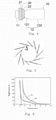
- the sheath core which is preferably a hard sheath core of a regular size, extends through the luminal stent, and the changing speed of the outer diameter of a force application part, as shown in Fig. 5 , of a radial force tester is set at 0.1 mm/s until the sheath core is in close contact with the luminal stent.
- a series of discrete values can be obtained through the test method, and are connected into a relation curve of the radial force and the compression value, as shown in Fig. 6 , wherein the X axis represents the compression diameter, and the Y axis represents the applied radial force.
- the compression curve L2 of the first tube body 11 is taken for example. Tangent lines of discrete points are respectively made on the compression curve L2 to obtain a plurality of intersections between the tangent lines and the X axis, and two points D1 and D2 are selected from these intersections. If the absolute value of the difference value between the two points D1 and D2 is not more than 0.01, it is defined in D1 and D2 that D1 is the compression diameter of the first tube body 11. As shown in Fig.
- the luminal stent before being implanted into the blood vessel, the luminal stent is required to be compressed into the sheath 30 at first, and the sheath core 31 is enabled to extend through the luminal stent.
- the diameter of the part encircled by the skirt 20 of the first tube body 11 is less than that of the second tube body 12, the compression diameters of the completely compressed skirt 20 and the completely compressed first tube body 11 encircled by the skirt 20 are basically equal to the compression diameter of the second tube body 12.
- the diameter of the second tube body of the luminal stent of the present application is greater than that of the first tube body, so that the second tube body is in closer contact with the sheath core after the luminal stent is compressed into the sheath. Furthermore, after compression, the maximum compression diameter of the second tube body is approximately equal to that of the first tube body encircled by the skirt, so that a contact force of the luminal stent with the sheath core in the sheath is more uniform, which may prevent the luminal stent from sliding during the release process and avoid the risk caused by the displacement of the luminal stent.
- first tube body 11 has a part not encircled by the skirt 20 and this part has a relatively short axial length (generally not more than 2 cm), sliding of this part relative to the sheath core would not occur even though the diameter of this part is not greater than that of the part encircled by the skirt.
- the diameter of this part may be designed to be greater than that of the part encircled by the skirt of the first tube body.
- the first tube body includes a first coating membrane and a first radial supporting structure connected with the first coating membrane.
- the second tube body includes a second coating membrane and a second radial supporting structure connected with the second coating membrane.
- the first radial supporting structure includes multiple first waveform ring-like objects arrayed in sequence
- the second radial supporting structure includes multiple second waveform ring-like objects arrayed in sequence.
- the thickness of the first coating membrane is equal to that of the second coating membrane, and the wire diameters of the first waveform ring-like objects are equal.
- the luminal stent structure of the present embodiment is basically the same as that of the first embodiment.
- the first tube body 11 in an expanded state has a varying diameter along its axial direction
- the second tube body 12 is of a straight barrel shape, namely any two points along the axial direction have the same in diameter d3.
- the part encircled by the skirt 20 of the first tube body 11 has a first maximum diameter d1
- the cross section of the first tube body 11 has a stepped shape.
- the skirt 20 is completely compressed into the part having the first diameter d1, and the compression diameter of the part encircled by the skirt 20 is equal to d2 and d3.
- the part having the relatively large diameter d2 is located at a position away from the skirt 20, and this position is an inlet end of the blood flow.
- the relatively large diameter d2 may allow a contact area between the first tube body 11 and the blood to be larger, and allow blood to flow into the first tube body 11 more easily.
- the diameters of the first tube body 11 and the second tube body 12 also may vary in various ways along their axial directions. For example, the diameter of the first tube body 11 may be gradually decreased along a direction close to a joint of the skirt 20 and the tube body 10.
- the luminal stent structure of the present embodiment is basically the same as that of the first embodiment.
- the first tube body 11 and the second tube body 12 are the same in diameter.
- the thickness of the first coating membrane 113 of the first tube body 11 is less than that of the second coating membrane 123 of the second tube body 12.
- a ratio of the thickness of the second coating membrane 123 to the thickness of the first coating membrane 113 is 1.2 - 4.5.
- the ratio of the thickness of the second coating membrane to the thickness of the first coating membrane may be adjusted according to the structure of the skirt so as to keep the compression diameter of the luminal stent basically consistent.
- the metal coverage rate of the first radial supporting structure of the first tube body 11 is less than that of the second tube body 12.
- the wire diameter of the first waveform ring-like object 115 is greater than that of the second waveform ring-like object 125.
- both the first waveform ring-like object 115 and the second waveform ring-like object 125 include the same number of wave crests and have equal wave heights.
- the ratio of the wire diameter of the second waveform ring-like object 125 to the wire diameter of the first waveform ring-like object 115 is 2.0 - 5.0 so as to enable the compression diameters of all parts of the luminal stent to be approximately the same.
- the number of the wave crests of the first waveform ring-like object 115 is less than that of the wave crests of the second waveform ring-like object 125.
- the first waveform ring-like object 115 and the second waveform ring-like object 125 adopt the same wire diameters and equal wave heights, and a ratio of the number of the wave crests of the second waveform ring-like object 125 to the number of the wave crests of the first waveform ring-like object 115 is 4 - 23.
- the thickness of the first coating membrane and the metal coverage rate of the first radial supporting structure of the first tube body and the thickness of the second coating membrane and the metal coverage rate of the second radial supporting structure of the second tube body also may be adjusted simultaneously according to a a desired clinical situation, so as to ensure that the compression diameters of all the parts of the luminal stent are approximately equal.
- the above-mentioned embodiments may also be combined with one another under certain conditions.
- the thickness of the first coating membrane and the metal coverage rate of the first radial supporting structure of the first tube body and the thickness of the second coating membrane and the metal coverage rate of the second radial supporting structure of the second tube body also may be further adjusted, so as to ensure that the compression diameters of all the parts of the luminal stent are approximately equal.
Description
- The present application relates to a cardiovascular medical device, and more particularly relates to a luminal stent.
- In intravascular interventional therapy, both a fenestration technology and a parallel stent technology are used to solve the problem of blood supply to branch vessels.
CN 105 496 603 A discloses a stent-graft comprising a first body and a second body which is arranged as a sheath outside the first body. - The fenestration technology as shown in
Fig. 1 is taken as an example. Type-III endoleak may possibly occur between a side hole of alarge stent 1 and abranch stent 2 because of poor adherence of thebranch stent 2 to the side hole. To solve the endoleak problem, abranch stent 2 having an anti-leakage structure, such as a skirt, is generally used, and the anti-leakage structure is used to enhance the sealing effect. As shown inFig. 2 and Fig. 3 , thebranch stent 2 having askirt 3 is correspondingly required to be delivered by a sheath having a relatively large diameter D. Furthermore, as theskirt 3 exists, and the diameters of all parts of the sheath are equal in an axial direction, apart 21 that is covered by theskirt 3 of thebranch stent 2 and assembled into thesheath 4 would be pressed more closely onto a sheath core by the sheath, but apart 22 that is not covered by theskirt 3 would expand by itself to squeeze thesheath core 5 slightly and even form a gap from thesheath core 5. During the release, thepart 22 not covered by theskirt 3 and thesheath core 5 may slide relative to each other, thereby leading to the displacement of the stent. - For the shortcomings in the prior art, the present application provides a luminal stent which adapts to a relatively thin sheath and does not move during the release process.
- One technical solution adopted by the present application to solve the technical problems is to provide a luminal stent having a tube body which can be compressed and expanded in a radial direction, and an anti-leakage structure connected with the tube body. The tube body is divided by the anti-leakage structure into a first tube body located on one side of the anti-leakage structure and a second tube body located on the other side of the anti-leakage structure. At least part of the first tube body is encircled by the anti-leakage structure. In a compressed state, the second tube body and the anti-leakage structure together with the first tube body encircled by the anti-leakage structure have maximum compression diameters when compressed to the extreme limit by a radial force distributed uniformly along a circumferential direction of the luminal stent. The maximum compression diameters of the anti-leakage structure and the first tube body encircled by the anti-leakage structure are approximately equal to the maximum compression diameter of the second tube body.
- In one embodiment of the present application, the absolute value of the difference between the maximum compression diameters of the anti-leakage structure together with the part encircled by the anti-leakage structure of the first tube body and the maximum compression diameter of the second tube body is no more than 0.1 mm.
- In one embodiment of the present application, the second tube body includes a tapered section connected with the first tube body and a straight barrel section connected with the tapered section. The diameter of the straight barrel section is greater than that of the part encircled by the anti-leakage structure of the first tube body.
- In one embodiment of the present application, the difference between the diameter of the straight barrel section and the diameter of the part encircled by the anti-leakage structure of the first tube body is no more than 8 mm.
- In one embodiment of the present application, the ratio of the difference between the diameter of the straight barrel section and the diameter of the part encircled by the anti-leakage structure of the first tube body to the diameter of the straight barrel section is 0.1 - 0.2.
- In one embodiment of the present application, the axial length of the tapered section is 5 to 10 mm.
- In one embodiment of the present application, the part encircled by the anti-leakage structure of the first tube body has a first diameter; and the part not encircled by the anti-leakage structure of the first tube body has a second diameter. The second diameter is unequal to the first diameter. The second diameter is greater than the first diameter.
- In one embodiment of the present application, the anti-leakage structure includes an outer-layer coating membrane and an outer-layer radial supporting structure connected with the outer-layer coating membrane.
- In one embodiment of the present application, the anti-leakage structure has an open end and a closed end. The closed end is located at a joint of the first tube body and the second tube body.
- In one embodiment of the present application, the first tube body includes a first coating membrane and a first radial supporting structure connected with the first coating membrane. The second tube body includes a second coating membrane connected with the first coating membrane and a second radial supporting structure connected with the second coating membrane. The thickness of the first coating membrane is less than that of the second coating membrane, and/or, the metal coverage rate of the first radial supporting structure is smaller than that of the second radial supporting structure.
- In one embodiment of the present application, the first radial supporting structure includes multiple first waveform ring-like objects arrayed in sequence, and the second radial supporting structure includes multiple second waveform ring-like objects arrayed in sequence. The wire diameter of each first waveform ring-like object is less than that of each second waveform ring-like object, and/or, the number of wave crests of each first waveform ring-like object is less than that of wave crests of each second waveform ring-like object.
- In one embodiment of the present application, the ratio of the thickness of the second coating membrane to the thickness of the first coating membrane is 1.2 - 4.5.
- In one embodiment of the present application, the ratio of the wire diameter of each second waveform ring-like object to the wire diameter of each first waveform ring-like object is 2.0 - 5.0.
- In one embodiment of the present application, a ratio of the number of the wave crests of each second waveform ring-like object to the number of the wave crests of each first waveform ring-like object is 4 - 23.
- The diameter of the second tube body of the luminal stent of the present application is greater than that of the first tube body, so that the second tube body is in closer contact with the sheath core after the luminal stent is compressed into the sheath. Furthermore, after compression, the maximum compression diameter of the second tube body is approximately equal to that of the first tube body encircled by a skirt, so that a contact force of the luminal stent with the sheath core in the sheath is more uniform, which may prevent the luminal stent from sliding in the release process and avoid the risk caused by the displacement of the luminal stent.
- The present application will be further described below in combination with accompanying the drawings and embodiments. In the drawings:
-
Fig. 1 is a structural schematic diagram of a luminal stent system in the prior art; -
Fig. 2 is a structural schematic diagram of a branch stent of the luminal stent system in the prior art shown in an expanded state; -
Fig. 3 is a structural schematic diagram of the branch stent in a compressed state in a sheath in the luminal stent system in the prior art; -
Fig. 4 is a structural schematic diagram of a first embodiment of a luminal stent of the present application shown in an expanded state; -
Fig. 5 is a structural schematic diagram of a force application part of a radial force tester of the present application; -
Fig. 6 is a compression curve chart of a first tube body and a second tube body in the first embodiment of the luminal stent of the present application; -
Fig. 7 is a structural schematic diagram of the luminal stent inFig. 4 in a compressed state in a sheath; -
Fig. 8 is a structural schematic diagram of a second embodiment of a luminal stent of the present application shown in an expanded state; -
Fig. 9 is a structural schematic diagram of the luminal stent ofFig. 8 in a compressed state in a sheath; -
Fig. 10 is a structural schematic diagram of a third embodiment of a luminal stent of the present application shown in an expanded state; -
Fig. 11 is a structural schematic diagram of a fourth embodiment of a luminal stent of the present application shown in an expanded state; and -
Fig. 12 is a structural schematic diagram of a fifth embodiment of a luminal stent of the present application shown in an expanded state. - To understand the technical features, objectives and effects of the present application more clearly, specific implementation modes of the present application are described in detail now in combination with the accompanying drawings.
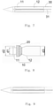
- As shown in
Fig. 4 , a luminal stent includes a straight barrel shapedtube body 10 and an anti-leakage structure arranged around thetube body 10 and connected with thetube body 10. Thetube body 10 is of a membrane-coated stent structure having a radial supporting structure (not shown in the figure) and a coating membrane (not shown in the figure) covering the radial supporting structure. The radial supporting structure may be made of metal or other materials, such as stainless steel, a shape memory alloy, a titanium alloy or a polymer. The radical supporting structure includes multiple waveform ring-like objects (not shown in the figure) uniformly arrayed along the axial direction of the stent. The coating membrane is a biocompatible thin film made of polytetrafluoroethylene or terylene commonly used in this field. The self-expandable hollowcolumnar tube body 10 may be compressed and may expand in its radial direction.Fig. 4 is the structural schematic diagram of the tube body in its expanded state. - In the present embodiment, the anti-leakage structure is a
skirt 20. In other embodiments, the anti-leakage structure may also have a capsular structure or a water-absorbing "fluffy" structure. The capsular structure is filled with a gel-like substance. The "fluffy" structure may further stop blood flow and accelerate the thrombolysis, in addition to preventing endoleak. - The
skirt 20 includes an outer-layerradial supporting structure 21 and an outer-layer coating membrane 22 covering the outer-layer radial supporting structure. The self-expandable skirt 20 may be compressed and may expand in its radial direction. In one embodiment, the radial deformability of theradial supporting structure 21 of theskirt 20 is greater than that of a stent body of thetube body 10. The radial deformability is defined as: under the action of the same radial force, a greater radial length variation or a greater radial length change rate indicates higher radial deformability and lower radial supportability of the radial supporting structure, and on the contrary, a lesser radial length variation or a lesser radial length change rate indicates lower radial deformability and higher radial supportability. In other words, under the condition of the same radial change rate or the same radial variation, a radial external force required by the outer-layerradial supporting structure 21 of theskirt 20 is greater than that required by the stent body of thetube body 10, which indicates that the outer-layerradial supporting structure 21 is relatively low in radial deformability and relatively high in radial supportability; please refer toCN105496603A for more details. In other possible embodiments, theskirt 20 may also include only the coating membrane. A gap between thetube body 10 and a blood vessel is filled with the soft coating membrane so as to prevent the endoleak. The outer-layerradial supporting structure 21 provides theskirt 20 with a radial expandability which also may be called the radial supportability or radial supporting force. For example, the radial supporting structure may be made of a memory alloy material (such as a nickel-titanium alloy) so as to be self-expandable. The outer-layerradial supporting structure 21 may have multiple turns of waveform ring-like objects arrayed along the axial direction, or may be a mesh structure woven from a metal wire, or may be a cut mesh structure that is cut from a metal tube. Those ordinarily skilled in the art can select proper radial supporting structures as required, so no more details will be provided here. - The
skirt 20 has an open end and a closed end. The open end has a column shape, and the closed end has a cone shape connected with a column. The closed end is hermetically connected with the surface of thetube body 10 so as to divide thetube body 10 into afirst tube body 11 encircled by theskirt 20 and located on one side of the closed end, and asecond tube body 12 located on the other side of the closed end. The open end of theskirt 20 extends towards a direction away from thesecond tube body 12, and the extending direction of thesecond tube body 12 is opposite to that of theskirt 20. When the luminal stent is compressed, theskirt 20 encircles the peripheral surface of thefirst tube body 11. Due to itsradial supporting structure 21, theskirt 20 may be adhered to the inner wall of a lumen after the stent is implanted, and an effective gap is formed between theskirt 20 and thefirst tube body 11. Blood would flow into the gap when flowing into the luminal stent from the proximal end. As the orifice at the closed end is closed, the blood flowing into the gap will be stopped so as to reduce and even avoid the blood flow from flowing into the gap formed between thesecond tube body 12 and the inner wall of the lumen, and to cut off a channel or an opening of a type-I endoleak. In addition, this part of the blood would be directly thrombosed in the gap to produce a better sealing and filling effect. In this sealing process, a sealing effect may be achieved only by use of the inflow blood in the normal blood circulation without adding other sealing or filling materials into the luminal stent in advance or after implantation of the luminal stent, so that no extra biological risk caused by the sealing or filling material would occur. In other possible embodiments of the present application, theskirt 20 may have a cone shape, excluding the column connected with the cone as shown inFig. 4 . - In the present embodiment, the thickness of the outer-
layer coating membrane 22 of theskirt 20 is 0.01 to 0.05mm, and the wire diameter of the outer-layerradial supporting structure 21 is 0.003 to 0.006 inch (0.0762 to 0.1534 mm). The thickness of the outer-layer coating membrane 20 is less than that of the coating membrane of thetube body 10, and the wire diameter of the outer-layerradial supporting structure 21 is less than that of the radial supporting structure of thetube body 10. - In addition, in other possible embodiments, both ends of the skirt are hermetically connected with the tube body. The skirt with the two closed ends may only include the coating membrane, or may further include the above-mentioned radial supporting structure.
- In the embodiment as shown in the figures, the
second tube body 12 includes a taperedsection 121 connected with thefirst tube body 11, and astraight barrel section 122 connected with the taperedsection 121. The end that is closest to thefirst tube body 11 of the taperedsection 121 has the same diameter as the part that is encircled by theskirt 20 of the first tube body. In addition, the end that is away from thefirst tube body 11 of the taperedsection 121 has the same diameter as that of thestraight barrel section 122. The diameter of the taperedsection 121 is gradually increased from the end closest to thefirst tube body 11 to the end closest to thestraight barrel section 122. In one embodiment, the axial length of the taperedsection 121 is 5 to 10 mm. In other words, the length of the taperedsection 121 along the longitudinal center axis of the tube body is 5 to 10 mm. The diameter of thestraight barrel section 122 is greater than that of the part that is encircled by theskirt 20 of thefirst tube body 11, and the axial length of thestraight barrel section 122 is greater than that of thefirst tube body 11. In one embodiment, in a natural expanded state, the difference between the diameter of thestraight barrel section 122 and the diameter of the part encircled by theskirt 20 of thefirst tube body 11 is no more than 8 mm, and the compression diameters of thefirst tube body 11 and thesecond tube body 12 are slightly different, so that after the luminal stent is compressed into the sheath, the contact force between thefirst tube body 11 and asheath core 31, as well as the contact force between thesecond tube body 12 and thesheath core 31, are increased. In one embodiment, in the natural state, the ratio of the difference between the diameter of thestraight barrel section 122 and the diameter of the part encircled by theskirt 20 of thefirst tube body 11 to the diameter of thestraight barrel section 122 is 0.1 to 0.2. In actual use, the oversized region of thestraight barrel section 122 of thesecond tube body 12 is [10 %, 20 %], namely the radial length of thesecond tube body 12 may be generally compressed by 10 to 20 percent after thesecond tube body 12 is implanted into the blood vessel to maintain a relatively high anchoring force between thestraight barrel section 122 of thesecond tube body 12 and the blood vessel wall, so that during the implantation into the blood vessel, the difference between the diameter of thefirst tube body 11 and the diameter of thestraight barrel section 122 of thesecond tube body 12 is relatively small, and the blood flow volumes of thefirst tube body 11 and thesecond tube body 12 may be kept consistent, which avoids the problem of turbulent flow in a connecting section due to inconsistent tube diameters of thefirst tube body 11 and thesecond tube body 12. In the present application, it is defined that when thefirst tube body 11, thesecond tube body 12, and theskirt 20 encircling the periphery of thefirst tube body 11 are compressed to the extreme limit by a radial force distributed along the circumferential direction uniformly of the luminal stent, their outer diameters are compression diameters, as shown inFig. 7 . The maximum compression diameters of theskirt 20 and thefirst tube body 11 encircled by theskirt 20 are approximately equal to the maximum compression diameter of thesecond tube body 12. In one embodiment, an absolute value of the difference between the maximum compression diameters of theskirt 20 together with thefirst tube body 11 encircled by theskirt 20 and the maximum compression diameter of thesecond tube body 12 is no more than 0.1 mm. The lesser the difference, the better. When the difference is close to 0, the luminal stent compressed into the sheath is an equal-diameter column, which means that the contact force between the luminal stent and the sheath core is uniform. It is worth noting that in the present embodiment, thetube body 10 is a column having a uniform tube diameter, so that its maximum compression diameter is the compression diameter. In other embodiments, if the tube diameter of thetube body 10 is not uniform, the compression diameter of a part having the maximum diameter shall be the maximum compression diameter. - Specifically, the compression diameter may be tested through the radial force. A functional relation between the compression diameter and the radial force is obtained by using a computer. When the compression amount is at a maximum, the increase of the force has little impact on the change of the compression amount, so that a curve of a stable increased force is obtained through computer fitting. Specifically, the sheath core, which is preferably a hard sheath core of a regular size, extends through the luminal stent, and the changing speed of the outer diameter of a force application part, as shown in
Fig. 5 , of a radial force tester is set at 0.1 mm/s until the sheath core is in close contact with the luminal stent. A series of discrete values can be obtained through the test method, and are connected into a relation curve of the radial force and the compression value, as shown inFig. 6 , wherein the X axis represents the compression diameter, and the Y axis represents the applied radial force. The compression curve L2 of thefirst tube body 11 is taken for example. Tangent lines of discrete points are respectively made on the compression curve L2 to obtain a plurality of intersections between the tangent lines and the X axis, and two points D1 and D2 are selected from these intersections. If the absolute value of the difference value between the two points D1 and D2 is not more than 0.01, it is defined in D1 and D2 that D1 is the compression diameter of thefirst tube body 11. As shown inFig. 7 , before being implanted into the blood vessel, the luminal stent is required to be compressed into thesheath 30 at first, and thesheath core 31 is enabled to extend through the luminal stent. As the diameter of the part encircled by theskirt 20 of thefirst tube body 11 is less than that of thesecond tube body 12, the compression diameters of the completely compressedskirt 20 and the completely compressedfirst tube body 11 encircled by theskirt 20 are basically equal to the compression diameter of thesecond tube body 12. - The diameter of the second tube body of the luminal stent of the present application is greater than that of the first tube body, so that the second tube body is in closer contact with the sheath core after the luminal stent is compressed into the sheath. Furthermore, after compression, the maximum compression diameter of the second tube body is approximately equal to that of the first tube body encircled by the skirt, so that a contact force of the luminal stent with the sheath core in the sheath is more uniform, which may prevent the luminal stent from sliding during the release process and avoid the risk caused by the displacement of the luminal stent.
- It can be understood that when the
first tube body 11 has a part not encircled by theskirt 20 and this part has a relatively short axial length (generally not more than 2 cm), sliding of this part relative to the sheath core would not occur even though the diameter of this part is not greater than that of the part encircled by the skirt. When thefirst tube body 11 has a relatively long part not encircled by the skirt, the diameter of this part may be designed to be greater than that of the part encircled by the skirt of the first tube body. - In the embodiment as shown in the figures, the first tube body includes a first coating membrane and a first radial supporting structure connected with the first coating membrane. The second tube body includes a second coating membrane and a second radial supporting structure connected with the second coating membrane. The first radial supporting structure includes multiple first waveform ring-like objects arrayed in sequence, and the second radial supporting structure includes multiple second waveform ring-like objects arrayed in sequence. The thickness of the first coating membrane is equal to that of the second coating membrane, and the wire diameters of the first waveform ring-like objects are equal.
- As shown in
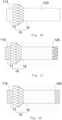
Fig. 8 , the luminal stent structure of the present embodiment is basically the same as that of the first embodiment. The difference lies in that in the present embodiment, thefirst tube body 11 in an expanded state has a varying diameter along its axial direction, and thesecond tube body 12 is of a straight barrel shape, namely any two points along the axial direction have the same in diameter d3. Specifically, the part encircled by theskirt 20 of thefirst tube body 11 has a first maximum diameter d1, and the part not encircled by theskirt 20 of thefirst tube body 11 has a second maximum diameter d2, with d1<d2=d3. In other words, the cross section of thefirst tube body 11 has a stepped shape. As shown inFig. 9 , due to the step-like structure of thefirst tube body 11, in a compressed state of the luminal stent, theskirt 20 is completely compressed into the part having the first diameter d1, and the compression diameter of the part encircled by theskirt 20 is equal to d2 and d3. - The part having the relatively large diameter d2 is located at a position away from the
skirt 20, and this position is an inlet end of the blood flow. The relatively large diameter d2 may allow a contact area between thefirst tube body 11 and the blood to be larger, and allow blood to flow into thefirst tube body 11 more easily. It is worth noting that the diameters of thefirst tube body 11 and thesecond tube body 12 also may vary in various ways along their axial directions. For example, the diameter of thefirst tube body 11 may be gradually decreased along a direction close to a joint of theskirt 20 and thetube body 10. - As shown in
Fig. 10 , the luminal stent structure of the present embodiment is basically the same as that of the first embodiment. The difference lies in that in the present embodiment, thefirst tube body 11 and thesecond tube body 12 are the same in diameter. Specifically, the thickness of thefirst coating membrane 113 of thefirst tube body 11 is less than that of thesecond coating membrane 123 of thesecond tube body 12. In one embodiment, a ratio of the thickness of thesecond coating membrane 123 to the thickness of thefirst coating membrane 113 is 1.2 - 4.5. Of course, the ratio of the thickness of the second coating membrane to the thickness of the first coating membrane may be adjusted according to the structure of the skirt so as to keep the compression diameter of the luminal stent basically consistent. - It can be further understood that the metal coverage rate of the first radial supporting structure of the
first tube body 11 is less than that of thesecond tube body 12. For example, as shown inFig. 11 , the wire diameter of the first waveform ring-like object 115 is greater than that of the second waveform ring-like object 125. Specifically, both the first waveform ring-like object 115 and the second waveform ring-like object 125 include the same number of wave crests and have equal wave heights. The ratio of the wire diameter of the second waveform ring-like object 125 to the wire diameter of the first waveform ring-like object 115 is 2.0 - 5.0 so as to enable the compression diameters of all parts of the luminal stent to be approximately the same. For another example, as shown inFig. 12 , the number of the wave crests of the first waveform ring-like object 115 is less than that of the wave crests of the second waveform ring-like object 125. Specifically, the first waveform ring-like object 115 and the second waveform ring-like object 125 adopt the same wire diameters and equal wave heights, and a ratio of the number of the wave crests of the second waveform ring-like object 125 to the number of the wave crests of the first waveform ring-like object 115 is 4 - 23. It can be further understood that the thickness of the first coating membrane and the metal coverage rate of the first radial supporting structure of the first tube body and the thickness of the second coating membrane and the metal coverage rate of the second radial supporting structure of the second tube body also may be adjusted simultaneously according to a a desired clinical situation, so as to ensure that the compression diameters of all the parts of the luminal stent are approximately equal. - It should be further noted that all the above-mentioned embodiments may also be combined with one another under certain conditions. For example, in the
embodiment 1, according to an actual condition, when the diameter of the first tube body is less than that of the second tube body, the thickness of the first coating membrane and the metal coverage rate of the first radial supporting structure of the first tube body and the thickness of the second coating membrane and the metal coverage rate of the second radial supporting structure of the second tube body also may be further adjusted, so as to ensure that the compression diameters of all the parts of the luminal stent are approximately equal. - The above-mentioned embodiments are merely expressive of several implementation modes of the present application, and descriptions are relatively specific and detailed, but cannot be understood as limitations to the patent scope of the present application. It should be noted that those ordinarily skilled in the art can further make a plurality of transformations and improvements without departing from the concept of the present application, and these transformations and improvements shall all fall within the protection scope of the present application. Therefore, the protection scope of the patent of the present application shall be based on attached claims.
Claims (14)
- A luminal stent, comprising:a tube body (10) that can be compressed and expanded in the radial direction; andan anti-leakage structure connected with the tube body (10), wherein the tube body (10) is divided by the anti-leakage structure into a first tube body (11) located on one side of the anti-leakage structure and a second tube body (12) located on the other side of the anti-leakage structure;at least part of the first tube body (11) is encircled by the anti-leakage structure;in a compressed state, the second tube body (12) and the anti-leakage structure together with the first tube body (11) encircled by the anti-leakage structure have maximum compression diameters when compressed to the extreme limit by a radial force distributed uniformly along a circumferential direction of the luminal stent; andthe maximum compression diameters of the anti-leakage structure together with the first tube body (11) encircled by the anti-leakage structure are approximately equal to the maximum compression diameter (D3) of the second tube body (12).
- The luminal stent according to claim 1, wherein an absolute value of the difference between the maximum compression diameters of the anti-leakage structure together with a part encircled by the anti-leakage structure of the first tube body, and the maximum compression diameter of the second tube body, is no more than 0.1 mm.
- The luminal stent according to claim 1, wherein the second tube body comprises a tapered section connected with the first tube body and a straight barrel section connected with the tapered section; and the diameter of the straight barrel section is greater than that of the part encircled by the anti-leakage structure of the first tube body.
- The luminal stent according to claim 3, wherein the difference between the diameter of the straight barrel section and the diameter of the part encircled by the anti-leakage structure of the first tube body is no more than 8 mm.
- The luminal stent according to claim 4, wherein a ratio of the difference between the diameter of the straight barrel section and the diameter of the part encircled by the anti-leakage structure of the first tube body to the diameter of the straight barrel section is 0.1 - 0.2.
- The luminal stent according to claim 3, wherein the axial length of the tapered section is 5 to 10 mm.
- The luminal stent according to claim 1, wherein a part encircled by the anti-leakage structure of the first tube body has a first diameter, and a part not encircled by the anti-leakage structure of the first tube body has a second diameter; with the second diameter being unequal to the first diameter, and the second diameter being greater than the first diameter.
- The luminal stent according to claim 1, wherein the anti-leakage structure comprises an outer-layer coating membrane (22) and an outer-layer radial supporting structure (21) connected with the outer-layer coating membrane.
- The luminal stent according to claim 8, wherein the anti-leakage structure has an open end and a closed end; and the closed end is located at a joint of the first tube body and the second tube body.
- The luminal stent according to claim 1, wherein the first tube body comprises a first coating membrane and a first radial supporting structure connected with the first coating membrane; the second tube body comprises a second coating membrane connected with the first coating membrane and a second radial supporting structure connected with the second coating membrane; the thickness of the first coating membrane is less than that of the second coating membrane, and/or, the metal coverage rate of the first radial supporting structure is smaller than that of the second radial supporting structure.
- The luminal stent according to claim 10, wherein the first radial supporting structure comprises multiple first waveform ring-like objects arrayed in sequence, and the second radial supporting structure comprises multiple second waveform ring-like objects arrayed in sequence; the wire diameter of each first waveform ring-like object is less than that of each second waveform ring-like object, and/or, the number of wave crests of each first waveform ring-like object is less than that of wave crests of each second waveform ring-like object.
- The luminal stent according to claim 10, wherein the ratio of the thickness of the second coating membrane to the thickness of the first coating membrane is 1.2 - 4.5.
- The luminal stent according to claim 11, wherein the ratio of the wire diameter of each second waveform ring-like object to the wire diameter of each first waveform ring-like object is 2.0 - 5.0.
- The luminal stent according to claim 11, wherein the ratio of the number of the wave crests of each second waveform ring-like object to the number of the wave crests of each first waveform ring-like object is 4 - 23.
Priority Applications (1)
| Application Number | Priority Date | Filing Date | Title |
|---|---|---|---|
| PL17889447T PL3563802T3 (en) | 2016-12-28 | 2017-12-06 | Luminal stent |
Applications Claiming Priority (2)
| Application Number | Priority Date | Filing Date | Title |
|---|---|---|---|
| CN201611238319 | 2016-12-28 | ||
| PCT/CN2017/114802 WO2018121197A1 (en) | 2016-12-28 | 2017-12-06 | Luminal stent |
Publications (3)
| Publication Number | Publication Date |
|---|---|
| EP3563802A1 EP3563802A1 (en) | 2019-11-06 |
| EP3563802A4 EP3563802A4 (en) | 2020-10-14 |
| EP3563802B1 true EP3563802B1 (en) | 2022-02-16 |
Family
ID=62706883
Family Applications (1)
| Application Number | Title | Priority Date | Filing Date |
|---|---|---|---|
| EP17889447.3A Active EP3563802B1 (en) | 2016-12-28 | 2017-12-06 | Luminal stent |
Country Status (6)
| Country | Link |
|---|---|
| US (1) | US11583383B2 (en) |
| EP (1) | EP3563802B1 (en) |
| CN (1) | CN109069258B (en) |
| ES (1) | ES2907220T3 (en) |
| PL (1) | PL3563802T3 (en) |
| WO (1) | WO2018121197A1 (en) |
Families Citing this family (8)
| Publication number | Priority date | Publication date | Assignee | Title |
|---|---|---|---|---|
| WO2020125226A1 (en) | 2018-12-18 | 2020-06-25 | 深圳市先健畅通医疗有限公司 | Lumen stent and implant |
| CN109646160A (en) * | 2019-01-29 | 2019-04-19 | 戴向晨 | Branched membrane-covered support in a kind of novel aorta |
| CN113116612B (en) * | 2019-12-31 | 2023-01-17 | 先健科技(深圳)有限公司 | Covered stent |
| CN113116613B (en) * | 2019-12-31 | 2023-10-20 | 先健科技(深圳)有限公司 | Tectorial membrane support |
| WO2022007560A1 (en) * | 2020-07-06 | 2022-01-13 | 深圳市先健畅通医疗有限公司 | Covered stent |
| CN113893062B (en) * | 2020-07-06 | 2023-01-03 | 先健科技(深圳)有限公司 | Covered stent |
| CN112603591B (en) * | 2020-12-01 | 2022-12-02 | 深圳市先健畅通医疗有限公司 | Covered stent |
| US20240032934A1 (en) * | 2022-07-29 | 2024-02-01 | Medtronic Vacular, Inc. | Method of treating short or no neck aneurysms |
Family Cites Families (16)
| Publication number | Priority date | Publication date | Assignee | Title |
|---|---|---|---|---|
| US5354308A (en) * | 1992-05-01 | 1994-10-11 | Beth Israel Hospital Association | Metal wire stent |
| US6273910B1 (en) * | 1999-03-11 | 2001-08-14 | Advanced Cardiovascular Systems, Inc. | Stent with varying strut geometry |
| US7044962B2 (en) * | 2002-06-25 | 2006-05-16 | Scimed Life Systems, Inc. | Implantable prosthesis with displaceable skirt |
| US7300459B2 (en) * | 2002-10-17 | 2007-11-27 | Heuser Richard R | Stent with covering and differential dilation |
| WO2004105651A1 (en) * | 2003-05-28 | 2004-12-09 | Cook Incorporated | Prosthetic valve with vessel engaging member |
| CN1961847A (en) * | 2005-11-09 | 2007-05-16 | 温宁 | Artificial heart valve with scaffold and delivery apparatus thereof |
| WO2008016578A2 (en) | 2006-07-31 | 2008-02-07 | Cartledge Richard G | Sealable endovascular implants and methods for their use |
| US20100121424A1 (en) | 2008-11-12 | 2010-05-13 | Petr Kubena | Stent compression tool |
| US8052741B2 (en) * | 2009-03-23 | 2011-11-08 | Medtronic Vascular, Inc. | Branch vessel prosthesis with a roll-up sealing assembly |
| EP2453836A4 (en) * | 2009-07-14 | 2016-02-17 | Endospan Ltd | Sideport engagement and sealing mechanism for endoluminal stent-grafts |
| US8333800B2 (en) * | 2010-04-29 | 2012-12-18 | Medtronic Vascular, Inc. | Mobile external coupling with internal sealing cuff for branch vessel connection |
| CA3051684C (en) * | 2011-12-06 | 2020-06-16 | Aortic Innovations Llc | Device for endovascular aortic repair and method of using the same |
| US9456897B2 (en) * | 2013-02-21 | 2016-10-04 | Medtronic, Inc. | Transcatheter valve prosthesis and a concurrently delivered sealing component |
| CN105496603B (en) | 2015-12-30 | 2018-11-06 | 先健科技(深圳)有限公司 | Intraluminal stent |
| CN105662511B (en) * | 2015-12-30 | 2018-10-26 | 先健科技(深圳)有限公司 | Intraluminal stent |
| CN206852682U (en) * | 2016-12-28 | 2018-01-09 | 先健科技(深圳)有限公司 | Intraluminal stent |
-
2017
- 2017-12-06 ES ES17889447T patent/ES2907220T3/en active Active
- 2017-12-06 CN CN201780002606.0A patent/CN109069258B/en active Active
- 2017-12-06 PL PL17889447T patent/PL3563802T3/en unknown
- 2017-12-06 WO PCT/CN2017/114802 patent/WO2018121197A1/en unknown
- 2017-12-06 EP EP17889447.3A patent/EP3563802B1/en active Active
- 2017-12-06 US US16/473,885 patent/US11583383B2/en active Active
Also Published As
| Publication number | Publication date |
|---|---|
| EP3563802A1 (en) | 2019-11-06 |
| EP3563802A4 (en) | 2020-10-14 |
| PL3563802T3 (en) | 2022-04-04 |
| CN109069258A (en) | 2018-12-21 |
| WO2018121197A1 (en) | 2018-07-05 |
| ES2907220T3 (en) | 2022-04-22 |
| US20200383769A1 (en) | 2020-12-10 |
| US11583383B2 (en) | 2023-02-21 |
| CN109069258B (en) | 2020-07-03 |
Similar Documents
| Publication | Publication Date | Title |
|---|---|---|
| EP3563802B1 (en) | Luminal stent | |
| US20190015227A1 (en) | Luminal stent | |
| US10702370B2 (en) | Lumen stent | |
| RU2180198C2 (en) | Expansible split stent | |
| US10743980B2 (en) | Lumen woven support | |
| US20070219610A1 (en) | Stent with flap | |
| CN109464212A (en) | Overlay film frame | |
| EP3733127B1 (en) | Luminal stent | |
| US20220354675A1 (en) | Endoluminal Stent and Endoluminal Stent System | |
| EP2519191B1 (en) | Filling structure for a graft system | |
| CN111228001B (en) | Lumen stent and in-situ windowing stent system | |
| CN110420075B (en) | Covered stent | |
| US11576768B2 (en) | Stent graft | |
| US10765853B2 (en) | Hemostatic valve system | |
| AU2017323542B2 (en) | Total arch concept | |
| CN206852682U (en) | Intraluminal stent | |
| CN111227991A (en) | Blood vessel stent and embedded branch stent thereof | |
| CN114224561A (en) | Intracranial vascular stent processing method | |
| US11612475B2 (en) | Blood conduit with stent | |
| JP2019122556A (en) | Stent | |
| US10327931B2 (en) | Pusher-assembly for an insertion system for a self-expandable vascular implant | |
| CN115624422B (en) | Blood vessel support | |
| CN210112754U (en) | Implant and method of manufacturing the same | |
| CN106073958B (en) | A kind of Medical rack and its manufacturing method | |
| US20200376253A1 (en) | Funnel-shaped pressurization valve |
Legal Events
| Date | Code | Title | Description |
|---|---|---|---|
| STAA | Information on the status of an ep patent application or granted ep patent |
Free format text: STATUS: THE INTERNATIONAL PUBLICATION HAS BEEN MADE |
|
| PUAI | Public reference made under article 153(3) epc to a published international application that has entered the european phase |
Free format text: ORIGINAL CODE: 0009012 |
|
| STAA | Information on the status of an ep patent application or granted ep patent |
Free format text: STATUS: REQUEST FOR EXAMINATION WAS MADE |
|
| 17P | Request for examination filed |
Effective date: 20190715 |
|
| AK | Designated contracting states |
Kind code of ref document: A1 Designated state(s): AL AT BE BG CH CY CZ DE DK EE ES FI FR GB GR HR HU IE IS IT LI LT LU LV MC MK MT NL NO PL PT RO RS SE SI SK SM TR |
|
| AX | Request for extension of the european patent |
Extension state: BA ME |
|
| DAV | Request for validation of the european patent (deleted) | ||
| DAX | Request for extension of the european patent (deleted) | ||
| A4 | Supplementary search report drawn up and despatched |
Effective date: 20200909 |
|
| RIC1 | Information provided on ipc code assigned before grant |
Ipc: A61F 2/07 20130101AFI20200904BHEP |
|
| GRAP | Despatch of communication of intention to grant a patent |
Free format text: ORIGINAL CODE: EPIDOSNIGR1 |
|
| STAA | Information on the status of an ep patent application or granted ep patent |
Free format text: STATUS: GRANT OF PATENT IS INTENDED |
|
| INTG | Intention to grant announced |
Effective date: 20210909 |
|
| GRAS | Grant fee paid |
Free format text: ORIGINAL CODE: EPIDOSNIGR3 |
|
| GRAA | (expected) grant |
Free format text: ORIGINAL CODE: 0009210 |
|
| STAA | Information on the status of an ep patent application or granted ep patent |
Free format text: STATUS: THE PATENT HAS BEEN GRANTED |
|
| AK | Designated contracting states |
Kind code of ref document: B1 Designated state(s): AL AT BE BG CH CY CZ DE DK EE ES FI FR GB GR HR HU IE IS IT LI LT LU LV MC MK MT NL NO PL PT RO RS SE SI SK SM TR |
|
| RAP3 | Party data changed (applicant data changed or rights of an application transferred) |
Owner name: LIFETECH SCIENTIFIC (SHENZHEN) CO., LTD. |
|
| REG | Reference to a national code |
Ref country code: GB Ref legal event code: FG4D |
|
| REG | Reference to a national code |
Ref country code: CH Ref legal event code: EP |
|
| REG | Reference to a national code |
Ref country code: DE Ref legal event code: R096 Ref document number: 602017053574 Country of ref document: DE |
|
| REG | Reference to a national code |
Ref country code: AT Ref legal event code: REF Ref document number: 1468431 Country of ref document: AT Kind code of ref document: T Effective date: 20220315 |
|
| REG | Reference to a national code |
Ref country code: IE Ref legal event code: FG4D |
|
| REG | Reference to a national code |
Ref country code: ES Ref legal event code: FG2A Ref document number: 2907220 Country of ref document: ES Kind code of ref document: T3 Effective date: 20220422 |
|
| REG | Reference to a national code |
Ref country code: GR Ref legal event code: EP Ref document number: 20220400633 Country of ref document: GR Effective date: 20220418 |
|
| REG | Reference to a national code |
Ref country code: LT Ref legal event code: MG9D |
|
| REG | Reference to a national code |
Ref country code: NL Ref legal event code: MP Effective date: 20220216 |
|
| REG | Reference to a national code |
Ref country code: AT Ref legal event code: MK05 Ref document number: 1468431 Country of ref document: AT Kind code of ref document: T Effective date: 20220216 |
|
| PG25 | Lapsed in a contracting state [announced via postgrant information from national office to epo] |
Ref country code: SE Free format text: LAPSE BECAUSE OF FAILURE TO SUBMIT A TRANSLATION OF THE DESCRIPTION OR TO PAY THE FEE WITHIN THE PRESCRIBED TIME-LIMIT Effective date: 20220216 Ref country code: RS Free format text: LAPSE BECAUSE OF FAILURE TO SUBMIT A TRANSLATION OF THE DESCRIPTION OR TO PAY THE FEE WITHIN THE PRESCRIBED TIME-LIMIT Effective date: 20220216 Ref country code: PT Free format text: LAPSE BECAUSE OF FAILURE TO SUBMIT A TRANSLATION OF THE DESCRIPTION OR TO PAY THE FEE WITHIN THE PRESCRIBED TIME-LIMIT Effective date: 20220616 Ref country code: NO Free format text: LAPSE BECAUSE OF FAILURE TO SUBMIT A TRANSLATION OF THE DESCRIPTION OR TO PAY THE FEE WITHIN THE PRESCRIBED TIME-LIMIT Effective date: 20220516 Ref country code: NL Free format text: LAPSE BECAUSE OF FAILURE TO SUBMIT A TRANSLATION OF THE DESCRIPTION OR TO PAY THE FEE WITHIN THE PRESCRIBED TIME-LIMIT Effective date: 20220216 Ref country code: LT Free format text: LAPSE BECAUSE OF FAILURE TO SUBMIT A TRANSLATION OF THE DESCRIPTION OR TO PAY THE FEE WITHIN THE PRESCRIBED TIME-LIMIT Effective date: 20220216 Ref country code: HR Free format text: LAPSE BECAUSE OF FAILURE TO SUBMIT A TRANSLATION OF THE DESCRIPTION OR TO PAY THE FEE WITHIN THE PRESCRIBED TIME-LIMIT Effective date: 20220216 Ref country code: BG Free format text: LAPSE BECAUSE OF FAILURE TO SUBMIT A TRANSLATION OF THE DESCRIPTION OR TO PAY THE FEE WITHIN THE PRESCRIBED TIME-LIMIT Effective date: 20220516 |
|
| PG25 | Lapsed in a contracting state [announced via postgrant information from national office to epo] |
Ref country code: LV Free format text: LAPSE BECAUSE OF FAILURE TO SUBMIT A TRANSLATION OF THE DESCRIPTION OR TO PAY THE FEE WITHIN THE PRESCRIBED TIME-LIMIT Effective date: 20220216 Ref country code: FI Free format text: LAPSE BECAUSE OF FAILURE TO SUBMIT A TRANSLATION OF THE DESCRIPTION OR TO PAY THE FEE WITHIN THE PRESCRIBED TIME-LIMIT Effective date: 20220216 Ref country code: AT Free format text: LAPSE BECAUSE OF FAILURE TO SUBMIT A TRANSLATION OF THE DESCRIPTION OR TO PAY THE FEE WITHIN THE PRESCRIBED TIME-LIMIT Effective date: 20220216 |
|
| PG25 | Lapsed in a contracting state [announced via postgrant information from national office to epo] |
Ref country code: IS Free format text: LAPSE BECAUSE OF FAILURE TO SUBMIT A TRANSLATION OF THE DESCRIPTION OR TO PAY THE FEE WITHIN THE PRESCRIBED TIME-LIMIT Effective date: 20220617 |
|
| PG25 | Lapsed in a contracting state [announced via postgrant information from national office to epo] |
Ref country code: SM Free format text: LAPSE BECAUSE OF FAILURE TO SUBMIT A TRANSLATION OF THE DESCRIPTION OR TO PAY THE FEE WITHIN THE PRESCRIBED TIME-LIMIT Effective date: 20220216 Ref country code: SK Free format text: LAPSE BECAUSE OF FAILURE TO SUBMIT A TRANSLATION OF THE DESCRIPTION OR TO PAY THE FEE WITHIN THE PRESCRIBED TIME-LIMIT Effective date: 20220216 Ref country code: RO Free format text: LAPSE BECAUSE OF FAILURE TO SUBMIT A TRANSLATION OF THE DESCRIPTION OR TO PAY THE FEE WITHIN THE PRESCRIBED TIME-LIMIT Effective date: 20220216 Ref country code: EE Free format text: LAPSE BECAUSE OF FAILURE TO SUBMIT A TRANSLATION OF THE DESCRIPTION OR TO PAY THE FEE WITHIN THE PRESCRIBED TIME-LIMIT Effective date: 20220216 Ref country code: DK Free format text: LAPSE BECAUSE OF FAILURE TO SUBMIT A TRANSLATION OF THE DESCRIPTION OR TO PAY THE FEE WITHIN THE PRESCRIBED TIME-LIMIT Effective date: 20220216 Ref country code: CZ Free format text: LAPSE BECAUSE OF FAILURE TO SUBMIT A TRANSLATION OF THE DESCRIPTION OR TO PAY THE FEE WITHIN THE PRESCRIBED TIME-LIMIT Effective date: 20220216 |
|
| REG | Reference to a national code |
Ref country code: DE Ref legal event code: R097 Ref document number: 602017053574 Country of ref document: DE |
|
| PG25 | Lapsed in a contracting state [announced via postgrant information from national office to epo] |
Ref country code: AL Free format text: LAPSE BECAUSE OF FAILURE TO SUBMIT A TRANSLATION OF THE DESCRIPTION OR TO PAY THE FEE WITHIN THE PRESCRIBED TIME-LIMIT Effective date: 20220216 |
|
| PLBE | No opposition filed within time limit |
Free format text: ORIGINAL CODE: 0009261 |
|
| STAA | Information on the status of an ep patent application or granted ep patent |
Free format text: STATUS: NO OPPOSITION FILED WITHIN TIME LIMIT |
|
| 26N | No opposition filed |
Effective date: 20221117 |
|
| PG25 | Lapsed in a contracting state [announced via postgrant information from national office to epo] |
Ref country code: SI Free format text: LAPSE BECAUSE OF FAILURE TO SUBMIT A TRANSLATION OF THE DESCRIPTION OR TO PAY THE FEE WITHIN THE PRESCRIBED TIME-LIMIT Effective date: 20220216 |
|
| PGFP | Annual fee paid to national office [announced via postgrant information from national office to epo] |
Ref country code: PL Payment date: 20221122 Year of fee payment: 6 |
|
| PGFP | Annual fee paid to national office [announced via postgrant information from national office to epo] |
Ref country code: ES Payment date: 20230105 Year of fee payment: 6 |
|
| P01 | Opt-out of the competence of the unified patent court (upc) registered |
Effective date: 20230515 |
|
| REG | Reference to a national code |
Ref country code: CH Ref legal event code: PL |
|
| GBPC | Gb: european patent ceased through non-payment of renewal fee |
Effective date: 20221206 |
|
| REG | Reference to a national code |
Ref country code: BE Ref legal event code: MM Effective date: 20221231 |
|
| PG25 | Lapsed in a contracting state [announced via postgrant information from national office to epo] |
Ref country code: LU Free format text: LAPSE BECAUSE OF NON-PAYMENT OF DUE FEES Effective date: 20221206 |
|
| PG25 | Lapsed in a contracting state [announced via postgrant information from national office to epo] |
Ref country code: LI Free format text: LAPSE BECAUSE OF NON-PAYMENT OF DUE FEES Effective date: 20221231 Ref country code: IE Free format text: LAPSE BECAUSE OF NON-PAYMENT OF DUE FEES Effective date: 20221206 Ref country code: GB Free format text: LAPSE BECAUSE OF NON-PAYMENT OF DUE FEES Effective date: 20221206 Ref country code: CH Free format text: LAPSE BECAUSE OF NON-PAYMENT OF DUE FEES Effective date: 20221231 |
|
| PG25 | Lapsed in a contracting state [announced via postgrant information from national office to epo] |
Ref country code: BE Free format text: LAPSE BECAUSE OF NON-PAYMENT OF DUE FEES Effective date: 20221231 |
|
| PGFP | Annual fee paid to national office [announced via postgrant information from national office to epo] |
Ref country code: GR Payment date: 20231122 Year of fee payment: 7 |
|
| PGFP | Annual fee paid to national office [announced via postgrant information from national office to epo] |
Ref country code: IT Payment date: 20231211 Year of fee payment: 7 Ref country code: FR Payment date: 20231220 Year of fee payment: 7 Ref country code: DE Payment date: 20231208 Year of fee payment: 7 |
|
| PGFP | Annual fee paid to national office [announced via postgrant information from national office to epo] |
Ref country code: PL Payment date: 20231122 Year of fee payment: 7 |
|
| PG25 | Lapsed in a contracting state [announced via postgrant information from national office to epo] |
Ref country code: HU Free format text: LAPSE BECAUSE OF FAILURE TO SUBMIT A TRANSLATION OF THE DESCRIPTION OR TO PAY THE FEE WITHIN THE PRESCRIBED TIME-LIMIT; INVALID AB INITIO Effective date: 20171206 |
|
| PGFP | Annual fee paid to national office [announced via postgrant information from national office to epo] |
Ref country code: ES Payment date: 20240108 Year of fee payment: 7 |