EP3563772B1 - Appareil de collecte de tissus - Google Patents
Appareil de collecte de tissus Download PDFInfo
- Publication number
- EP3563772B1 EP3563772B1 EP19182350.9A EP19182350A EP3563772B1 EP 3563772 B1 EP3563772 B1 EP 3563772B1 EP 19182350 A EP19182350 A EP 19182350A EP 3563772 B1 EP3563772 B1 EP 3563772B1
- Authority
- EP
- European Patent Office
- Prior art keywords
- fluid
- tissue
- conduit
- needle
- needles
- Prior art date
- Legal status (The legal status is an assumption and is not a legal conclusion. Google has not performed a legal analysis and makes no representation as to the accuracy of the status listed.)
- Active
Links
- 238000003306 harvesting Methods 0.000 title description 70
- 239000012530 fluid Substances 0.000 claims description 101
- 238000004891 communication Methods 0.000 claims description 12
- 239000000203 mixture Substances 0.000 claims description 4
- FAPWRFPIFSIZLT-UHFFFAOYSA-M Sodium chloride Chemical compound [Na+].[Cl-] FAPWRFPIFSIZLT-UHFFFAOYSA-M 0.000 claims description 3
- 239000000872 buffer Substances 0.000 claims description 3
- 239000003102 growth factor Substances 0.000 claims description 3
- 239000011780 sodium chloride Substances 0.000 claims description 3
- 210000001519 tissue Anatomy 0.000 description 102
- 238000000034 method Methods 0.000 description 20
- 239000000758 substrate Substances 0.000 description 16
- 230000035515 penetration Effects 0.000 description 13
- 238000003780 insertion Methods 0.000 description 8
- 230000037431 insertion Effects 0.000 description 8
- 210000003491 skin Anatomy 0.000 description 7
- 238000010586 diagram Methods 0.000 description 6
- 239000011148 porous material Substances 0.000 description 5
- 230000000717 retained effect Effects 0.000 description 4
- 230000035899 viability Effects 0.000 description 4
- 230000008901 benefit Effects 0.000 description 3
- 210000004207 dermis Anatomy 0.000 description 3
- 239000007788 liquid Substances 0.000 description 3
- 210000000056 organ Anatomy 0.000 description 3
- 231100000241 scar Toxicity 0.000 description 3
- 210000004003 subcutaneous fat Anatomy 0.000 description 3
- 208000032544 Cicatrix Diseases 0.000 description 2
- 238000013459 approach Methods 0.000 description 2
- 238000001574 biopsy Methods 0.000 description 2
- 230000015572 biosynthetic process Effects 0.000 description 2
- 238000011109 contamination Methods 0.000 description 2
- 239000002537 cosmetic Substances 0.000 description 2
- 230000002500 effect on skin Effects 0.000 description 2
- 238000000227 grinding Methods 0.000 description 2
- 230000035876 healing Effects 0.000 description 2
- 238000004519 manufacturing process Methods 0.000 description 2
- 239000000463 material Substances 0.000 description 2
- 238000005259 measurement Methods 0.000 description 2
- 235000015097 nutrients Nutrition 0.000 description 2
- 238000012545 processing Methods 0.000 description 2
- 230000037390 scarring Effects 0.000 description 2
- 230000037387 scars Effects 0.000 description 2
- 238000000926 separation method Methods 0.000 description 2
- UCSJYZPVAKXKNQ-HZYVHMACSA-N streptomycin Chemical compound CN[C@H]1[C@H](O)[C@@H](O)[C@H](CO)O[C@H]1O[C@@H]1[C@](C=O)(O)[C@H](C)O[C@H]1O[C@@H]1[C@@H](NC(N)=N)[C@H](O)[C@@H](NC(N)=N)[C@H](O)[C@H]1O UCSJYZPVAKXKNQ-HZYVHMACSA-N 0.000 description 2
- 239000000126 substance Substances 0.000 description 2
- 238000013519 translation Methods 0.000 description 2
- 229930183010 Amphotericin Natural products 0.000 description 1
- QGGFZZLFKABGNL-UHFFFAOYSA-N Amphotericin A Natural products OC1C(N)C(O)C(C)OC1OC1C=CC=CC=CC=CCCC=CC=CC(C)C(O)C(C)C(C)OC(=O)CC(O)CC(O)CCC(O)C(O)CC(O)CC(O)(CC(O)C2C(O)=O)OC2C1 QGGFZZLFKABGNL-UHFFFAOYSA-N 0.000 description 1
- 239000006144 Dulbecco’s modified Eagle's medium Substances 0.000 description 1
- WQZGKKKJIJFFOK-GASJEMHNSA-N Glucose Natural products OC[C@H]1OC(O)[C@H](O)[C@@H](O)[C@@H]1O WQZGKKKJIJFFOK-GASJEMHNSA-N 0.000 description 1
- 241000282412 Homo Species 0.000 description 1
- 229930182555 Penicillin Natural products 0.000 description 1
- JGSARLDLIJGVTE-MBNYWOFBSA-N Penicillin G Chemical compound N([C@H]1[C@H]2SC([C@@H](N2C1=O)C(O)=O)(C)C)C(=O)CC1=CC=CC=C1 JGSARLDLIJGVTE-MBNYWOFBSA-N 0.000 description 1
- 239000004809 Teflon Substances 0.000 description 1
- 229920006362 Teflon® Polymers 0.000 description 1
- 230000004913 activation Effects 0.000 description 1
- 210000000577 adipose tissue Anatomy 0.000 description 1
- 230000002411 adverse Effects 0.000 description 1
- 150000001413 amino acids Chemical class 0.000 description 1
- 229940009444 amphotericin Drugs 0.000 description 1
- APKFDSVGJQXUKY-INPOYWNPSA-N amphotericin B Chemical compound O[C@H]1[C@@H](N)[C@H](O)[C@@H](C)O[C@H]1O[C@H]1/C=C/C=C/C=C/C=C/C=C/C=C/C=C/[C@H](C)[C@@H](O)[C@@H](C)[C@H](C)OC(=O)C[C@H](O)C[C@H](O)CC[C@@H](O)[C@H](O)C[C@H](O)C[C@](O)(C[C@H](O)[C@H]2C(O)=O)O[C@H]2C1 APKFDSVGJQXUKY-INPOYWNPSA-N 0.000 description 1
- 239000003242 anti bacterial agent Substances 0.000 description 1
- 229940088710 antibiotic agent Drugs 0.000 description 1
- 229940121375 antifungal agent Drugs 0.000 description 1
- 239000003429 antifungal agent Substances 0.000 description 1
- 238000003491 array Methods 0.000 description 1
- QVGXLLKOCUKJST-UHFFFAOYSA-N atomic oxygen Chemical compound [O] QVGXLLKOCUKJST-UHFFFAOYSA-N 0.000 description 1
- WQZGKKKJIJFFOK-VFUOTHLCSA-N beta-D-glucose Chemical compound OC[C@H]1O[C@@H](O)[C@H](O)[C@@H](O)[C@@H]1O WQZGKKKJIJFFOK-VFUOTHLCSA-N 0.000 description 1
- 230000000740 bleeding effect Effects 0.000 description 1
- 238000001816 cooling Methods 0.000 description 1
- 230000009849 deactivation Effects 0.000 description 1
- 230000001419 dependent effect Effects 0.000 description 1
- 230000008021 deposition Effects 0.000 description 1
- 238000006073 displacement reaction Methods 0.000 description 1
- 239000003792 electrolyte Substances 0.000 description 1
- 238000000605 extraction Methods 0.000 description 1
- RFHAOTPXVQNOHP-UHFFFAOYSA-N fluconazole Chemical compound C1=NC=NN1CC(C=1C(=CC(F)=CC=1)F)(O)CN1C=NC=N1 RFHAOTPXVQNOHP-UHFFFAOYSA-N 0.000 description 1
- 229960004884 fluconazole Drugs 0.000 description 1
- -1 for example Substances 0.000 description 1
- 239000002783 friction material Substances 0.000 description 1
- 239000007789 gas Substances 0.000 description 1
- 239000008103 glucose Substances 0.000 description 1
- 239000000314 lubricant Substances 0.000 description 1
- 239000011159 matrix material Substances 0.000 description 1
- 239000002184 metal Substances 0.000 description 1
- 238000012986 modification Methods 0.000 description 1
- 230000004048 modification Effects 0.000 description 1
- 230000003287 optical effect Effects 0.000 description 1
- 239000001301 oxygen Substances 0.000 description 1
- 229910052760 oxygen Inorganic materials 0.000 description 1
- 230000037361 pathway Effects 0.000 description 1
- 229940049954 penicillin Drugs 0.000 description 1
- 230000002572 peristaltic effect Effects 0.000 description 1
- 230000035699 permeability Effects 0.000 description 1
- 230000008569 process Effects 0.000 description 1
- 230000001681 protective effect Effects 0.000 description 1
- 238000007789 sealing Methods 0.000 description 1
- 125000006850 spacer group Chemical group 0.000 description 1
- 230000000087 stabilizing effect Effects 0.000 description 1
- 229910001220 stainless steel Inorganic materials 0.000 description 1
- 239000010935 stainless steel Substances 0.000 description 1
- 238000003860 storage Methods 0.000 description 1
- 229960005322 streptomycin Drugs 0.000 description 1
- 230000000153 supplemental effect Effects 0.000 description 1
- 229910000811 surgical stainless steel Inorganic materials 0.000 description 1
- 230000004083 survival effect Effects 0.000 description 1
- 239000003104 tissue culture media Substances 0.000 description 1
- 238000012546 transfer Methods 0.000 description 1
- 238000011282 treatment Methods 0.000 description 1
Images


Classifications
-
- A—HUMAN NECESSITIES
- A61—MEDICAL OR VETERINARY SCIENCE; HYGIENE
- A61B—DIAGNOSIS; SURGERY; IDENTIFICATION
- A61B17/00—Surgical instruments, devices or methods, e.g. tourniquets
- A61B17/32—Surgical cutting instruments
- A61B17/322—Skin grafting apparatus
-
- A—HUMAN NECESSITIES
- A61—MEDICAL OR VETERINARY SCIENCE; HYGIENE
- A61B—DIAGNOSIS; SURGERY; IDENTIFICATION
- A61B10/00—Other methods or instruments for diagnosis, e.g. instruments for taking a cell sample, for biopsy, for vaccination diagnosis; Sex determination; Ovulation-period determination; Throat striking implements
- A61B10/02—Instruments for taking cell samples or for biopsy
- A61B10/0233—Pointed or sharp biopsy instruments
-
- A—HUMAN NECESSITIES
- A61—MEDICAL OR VETERINARY SCIENCE; HYGIENE
- A61M—DEVICES FOR INTRODUCING MEDIA INTO, OR ONTO, THE BODY; DEVICES FOR TRANSDUCING BODY MEDIA OR FOR TAKING MEDIA FROM THE BODY; DEVICES FOR PRODUCING OR ENDING SLEEP OR STUPOR
- A61M1/00—Suction or pumping devices for medical purposes; Devices for carrying-off, for treatment of, or for carrying-over, body-liquids; Drainage systems
- A61M1/71—Suction drainage systems
- A61M1/79—Filters for solid matter
-
- A—HUMAN NECESSITIES
- A61—MEDICAL OR VETERINARY SCIENCE; HYGIENE
- A61B—DIAGNOSIS; SURGERY; IDENTIFICATION
- A61B10/00—Other methods or instruments for diagnosis, e.g. instruments for taking a cell sample, for biopsy, for vaccination diagnosis; Sex determination; Ovulation-period determination; Throat striking implements
- A61B10/02—Instruments for taking cell samples or for biopsy
- A61B10/0233—Pointed or sharp biopsy instruments
- A61B10/0283—Pointed or sharp biopsy instruments with vacuum aspiration, e.g. caused by retractable plunger or by connected syringe
-
- A—HUMAN NECESSITIES
- A61—MEDICAL OR VETERINARY SCIENCE; HYGIENE
- A61B—DIAGNOSIS; SURGERY; IDENTIFICATION
- A61B17/00—Surgical instruments, devices or methods, e.g. tourniquets
- A61B17/32—Surgical cutting instruments
- A61B17/3205—Excision instruments
- A61B17/32053—Punch like cutting instruments, e.g. using a cylindrical or oval knife
-
- A—HUMAN NECESSITIES
- A61—MEDICAL OR VETERINARY SCIENCE; HYGIENE
- A61B—DIAGNOSIS; SURGERY; IDENTIFICATION
- A61B17/00—Surgical instruments, devices or methods, e.g. tourniquets
- A61B2017/00743—Type of operation; Specification of treatment sites
- A61B2017/00747—Dermatology
- A61B2017/00752—Hair removal or transplantation
-
- A—HUMAN NECESSITIES
- A61—MEDICAL OR VETERINARY SCIENCE; HYGIENE
- A61B—DIAGNOSIS; SURGERY; IDENTIFICATION
- A61B17/00—Surgical instruments, devices or methods, e.g. tourniquets
- A61B17/30—Surgical pincettes without pivotal connections
- A61B2017/306—Surgical pincettes without pivotal connections holding by means of suction
-
- A—HUMAN NECESSITIES
- A61—MEDICAL OR VETERINARY SCIENCE; HYGIENE
- A61B—DIAGNOSIS; SURGERY; IDENTIFICATION
- A61B17/00—Surgical instruments, devices or methods, e.g. tourniquets
- A61B17/32—Surgical cutting instruments
- A61B17/322—Skin grafting apparatus
- A61B2017/3225—Skin grafting apparatus with processing of harvested tissue
-
- A—HUMAN NECESSITIES
- A61—MEDICAL OR VETERINARY SCIENCE; HYGIENE
- A61B—DIAGNOSIS; SURGERY; IDENTIFICATION
- A61B17/00—Surgical instruments, devices or methods, e.g. tourniquets
- A61B17/34—Trocars; Puncturing needles
- A61B17/3403—Needle locating or guiding means
- A61B2017/3405—Needle locating or guiding means using mechanical guide means
- A61B2017/3407—Needle locating or guiding means using mechanical guide means including a base for support on the body
-
- A—HUMAN NECESSITIES
- A61—MEDICAL OR VETERINARY SCIENCE; HYGIENE
- A61B—DIAGNOSIS; SURGERY; IDENTIFICATION
- A61B2217/00—General characteristics of surgical instruments
- A61B2217/002—Auxiliary appliance
- A61B2217/005—Auxiliary appliance with suction drainage system
Definitions
- the present disclosure relates to an apparatus for fluid-assisted harvesting of small tissue specimens from a donor site.
- tissue copying and grafting are being developed, in which small columns of tissue (microscopic tissue columns, or MTCs) are removed from a donor site and can be used in various procedures such as, e.g., being introduced into a recipient site, implanted in a matrix, etc.
- MTCs microscopic tissue columns, or MTCs
- Such approaches are described, e.g., in International Patent Publication No. WO 2009/146068 .
- the MTCs are typically less than about 1 mm in diameter and their removal is well-tolerated by the donor site.
- the holes formed in a donor site by removal of MTCs can heal rapidly with little or no visible scar or marking formed because of the small size of the holes and their being surrounded by healthy tissue.
- These columns of living tissue can nucleate and/or stimulate growth of new tissue.
- the small size of the MTCs favors their survival in various environments.
- the MTCs can be harvested using a hollow needle. However, they tend to be fragile tissue samples that can be adversely affected by their surroundings and handling, e.g., they may be contaminated or mechanically stressed after being cut or otherwise separated and then removed from the donor site. Accordingly, it is desirable to provide a method and apparatus for harvesting MTCs that facilitates their rapid extraction from a donor site and subsequent retrieval and storage without damaging them.
- US 6 027 512 A discloses an apparatus for obtaining at least one portion of a biological tissue having a hollow tube, a conduit and a filter arrangement.
- an apparatus can be provided for harvesting small samples of biological tissue (e.g. microscopic tissue columns, or MTCs) that are typically less than about 1 mm in width, and may be longer in length.
- MTCs biological tissue
- the removal of such small MTCs can be well-tolerated by the donor site.
- the small regions of damage in the donor site caused by removal of the tissue samples heal rapidly with little or no formation of visible scars.
- the apparatus can facilitate harvesting MTCs that uses one or more hollow needles to extract the MTCs from a tissue donor site.
- an apparatus can be provided that includes one or more hollow harvesting or 'coring' needles, preferably extending from a housing. The distal end of the needle is configured to penetrate the tissue, so that a portion of tissue (an MTC) will be cut away from the surrounding tissue by the needle tip and walls, and located in a distal portion of the hollow lumen of the needle. The MTC can be removed from the surrounding tissue and remain in the lumen of the needle when the needle is withdrawn.
- An inner diameter of the hollow needle can be less than about 1 mm in diameter, e.g., between about 0.15 mm and 0.5 mm, for cosmetic treatments involving skin.
- larger diameters may be used to harvest samples from other tissues or organs that may be more tolerant of damage and/or for which visible scarring is not problematic.
- a conduit can be provided in the apparatus that is configured to circulate a fluid past a proximal end of each coring needle.
- the lumen of the hollow needle can be in fluid communication with the conduit. The flowing fluid helps to draw the MTC up through the lumen of the needle and into the fluid path after the MTC is separated from surrounding tissue, where the MTC can then be surrounded by a protective fluid environment.
- a filter arrangement that can include, e.g., a filter element, a mesh basket, or the like, can be provided in the flow path of the circulating fluid such that the harvested MTCs within the flowing fluid can then be trapped in the filter arrangement while the fluid passes through.
- the filter arrangement can be provided in a chamber, and a cap or cover can be provided to facilitate access to the harvested MTCs.
- a vent can optionally be provided to release air that may be entrained in the fluid during harvesting of the MTCs.
- the fluid containing entrained MTCs can be directed by a delivery arrangement onto a porous dressing or substrate external to the site.
- MTCs can be deposited directly from the flowing liquid onto a porous dressing, and the dressing with MTCs can then be applied directly to a wound site.
- the delivery arrangement and substrate can be moved relative to one another such that MTCs are deposited over a particular region of the dressing/substrate during the harvesting procedure.
- the porous dressing can be provided as part of the filter arrangement.
- the fluid characteristics can be selected to provide a gentle environment for the MTCs, to prevent contamination, and/or to promote their viability and growth.
- the fluid can be temperature-controlled using conventional thermal control systems.
- the fluid can contain a variety of substances, including saline, growth factors, buffers, etc.
- Various sensors and controllers can optionally be provided, e.g., to monitor and/or control such parameters as fluid temperature and flow rate, fluid composition, pressure at various locations within the apparatus, etc.
- An actuator such as a solenoid, a motor with a rotary/linear converter, or the like can be provided to direct the needles into the donor tissue and then withdraw them.
- Such actuators can be controlled using a conventional power source and controller arrangement.
- a lower portion of the exemplary apparatus can be shaped to create a recess between the tissue surface and a lower surface of the apparatus.
- One or more ducts can be provided in communication with this enclosed space, and a source of low pressure can be connected to the ducts to pull the tissue surface upward, thereby stretching and stabilizing the tissue to facilitate penetration by the needles.
- An elevated pressure can optionally be connected to the ducts after penetration by the needles to push the tissue back down.
- the needles can be held stationary with respect to the lower surface of the apparatus, and an alternating low and high pressure can be applied to pull the tissue onto the needles and then pull it away from them.
- the present disclosure relates to an apparatus for harvesting microscopic tissue columns (MTCs) that uses one or more hollow needles to extract the MTCs from a tissue donor site.
- An apparatus can be provided that includes one or more hollow harvesting or 'coring' needles.
- the inner diameter of the needle 100 can be selected to approximately correspond to a particular diameter of a tissue sample or MTC to be removed from the donor site as described herein.
- 18, 19 or 20 gauge biopsy needles e.g., having an inner diameter of 0.838 mm, 0.686 mm and 0.564 mm, respectively
- needles having a gauge size between 18 and 30 or the equivalent can be used for cosmetic applications such as skin resurfacing.
- the inner diameter of such needle 100 (e.g., the diameter of the central lumen) can be, e.g., between about 1 mm and about 0.15 mm, or preferably between about 0.5 mm and 0.15 mm.
- Such smaller inner diameters can be used to separate and remove MTCs having a similar width from surrounding tissue. MTCs having such small widths may exhibit desirable viability, for example, because nutrients can more readily be transported directly to more cells in the MTC from surrounding environment.
- a hollow needle or tube 100 having a slightly larger or smaller inner diameter can also be used in further embodiments, e.g. based on the type of tissue being harvested, if larger or smaller MTCs are desired. For example, larger diameters may be used to harvest samples from tissues or organs other than skin that may be more tolerant of damage and/or for which visible scarring is not problematic.
- the harvesting needle 100 shown in FIG. 1A includes a distal end that can be formed as a plurality of piercing arrangements (e.g., including points) 105.
- a side view of a distal end of the needle 100 is shown in FIG. 1B .
- the two exemplary points 105 shown in FIG. 1A can be formed by grinding flat bevels on opposite sides of the needle 100 at an angle ⁇ relative to the long axis of the needle, as shown in FIG. 1B .
- the angle ⁇ can be, e.g., between about 10° and about 25°, or between about 10° and 20°.
- the distal end of the harvesting needle 100 can be provided with three or more points 105, e.g., by forming three or more angled flat bevels at different orientations, and optionally at different angles.
- the exemplary points 105 and associated beveled edges can facilitate insertion of the distal end of the needle 100 into donor-site tissue and removal of MTCs therefrom.
- the distal end of the harvesting needle 100 can be configured to penetrate the tissue, so that a portion of tissue (an MTC) will be cut away from the surrounding tissue by the needle tips 105 and adjacent beveled edges, such that the MTC will be located in the hollow lumen of the needle 100.
- the needle 100 can be formed of metal or another structurally rigid material, e.g., hypodermic stainless steel tubing or the like.
- the needles 100 can be formed from a small biopsy needle or a similar structure.
- a portion of the needle 100 can optionally be coated with a lubricant or low-friction material, such as Teflon ® , to further facilitate passage of the needle 100 through the donor site tissue.
- a rotating motion can be applied around the longitudinal axis of the needle 100 during insertion to facilitate penetration of the needle 100 into the tissue and/or separation and removal of an MTC from the surrounding tissue.
- Exemplary harvesting needles 100 were formed by grinding angled bevels into opposite sides of a surgical steel hypodermic needle to form two points, as illustrated schematically in FIGS. 1A and 1B .
- the bevel angle ⁇ was about 12°.
- Thin wall hypodermic needles of 19 and 22 gauge, and regular-wall needles of 25 and 30 gauge were used.
- These exemplary needles 100 were inserted into samples of pig and human skin tissue to a depth of the subcutaneous fat layer, and the penetration force was measured. The width of the resulting harvested MTCs was also measured. Data for this study is summarized in Table I below.
- Table 1 Mean diameter, D, of harvested MSTC and harvesting penetration force, F, for needles of different gauges: regular wall (RW), thin wall (TW), outer diameter (od), inner diameter (id). Mean force was obtained from two users and four independent measurements per user. Mean diameter was obtained from five independent measurements. Standard deviation of the mean is in parenthesis.
- the width of a harvested MTC was observed to correspond closely with the inner (lumen) diameter of the harvesting needle 100.
- Insertion force of any needle into human tissue was about 50-60% of the force needed to insert the same needle into pig skin tissue.
- the force measured to insert a single needle 100 was about 5-6 N. If a plurality of needles 100 are inserted simultaneously, the total force required would, to a first approximation, be about 5N multiplied by the number of needles 100 being inserted.
- Such force data can be used, e.g., to estimate the force requirements for devices having a plurality of harvesting needles 100, and can also set limits on how many such needles 100 can be inserted using a reasonable degree of force.
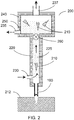
- FIG. 2 A cross-sectional view of a diagram of an apparatus 200 in accordance with certain exemplary embodiments of the present disclosure is shown in FIG. 2 .
- the exemplary apparatus 200 shown in FIG. 2 can include a housing 220 with a fluid conduit 225 provided therein.
- One or more harvesting needles 100 can be coupled to the housing 220.
- the fluid conduit 225 can be provided with at least one fluid inlet 230 and at least one fluid outlet 235.
- the fluid conduit 225 can be configured or structured such that a fluid can flow therethrough; e.g., the direction of fluid flow is indicated by the arrows in FIG. 2 .
- a proximal end of the needle lumen can be in a fluid communication with the conduit 225. For example, the fluid can flow past a proximal end of the harvesting needle 100, as shown in FIG. 2 .
- the exemplary apparatus 200 can be manipulated such that the distal end of one or more of the harvesting needles 100 penetrate the tissue 212 to a particular depth.
- the depth can be selected and/or controlled, e.g., by providing or adjusting a particular distance between the bottom of the housing 220 and the distal end of the one or more needles 100.
- a penetration depth can be selected that extends the distal end of one or more of the harvesting needles 100 through the entire local thickness of the dermis to about the depth of the subcutaneous fat layer, or optionally slightly into this fat layer.
- Inserting the needles 100 through the entire thickness of the dermis can provide an MTC 210 that has the full length of the dermis. Further, such exemplary depth can facilitate a separation of the MTC 210 from the surrounding tissue, because the proximal end of the needle 100 can cut the MTC 210 away from the adjacent dermal tissue, and the MTC 210 can then be fully detached by tearing a small amount of subcutaneous fat at the bottom of the MTC 210. Such fatty tissue may be more easily separable than denser dermal tissue. After the needle 100 is withdrawn from the donor site tissue 212, an MTC that was separated from the surrounding tissue 212 can remain within the lumen of the needle 100.
- the fluid flowing through the conduit 225 can reduce pressure at the proximal end of the needle 100, which can facilitate removal of the MTC 210 from the lumen of the needle 100.
- the MTC 210 can be entrained in the flowing liquid, and carried through the conduit 225 and into a chamber 240.
- the flowing fluid can be withdrawn from the fluid outlet 235, which can be provided as part of the chamber 240. MTCs that have been harvested as described herein can remain in the chamber 240.
- one or more vents 237 can be provided in an upper portion of the chamber 240 (or conduit 225, if no chamber is provided) to allow any air entrained during the harvesting procedure to escape from the conduit pathway, e.g., to prevent the chamber 240 from filling with air. For example, a small amount of air may be sucked in through the needle 100 along with an MTC 210 when the needle 100 is withdrawn from the donor tissue 212.
- the conduit 225 can form a closed loop for the fluid flow or otherwise recirculate fluid flowing through the apparatus 200.
- the fluid inlet 230 and outlet 235 shown in FIG. 2 can be connected to the outlet and inlet, respectively, of a fluid pump arrangement (not shown) or the like.
- the pump arrangement can be or include an external pump or similar device configured to circulate fluid through the conduit 225.
- the fluid can be provided from one or more reservoirs, and the pump arrangement and the conduit 225 can be configured, connected or structured such that the fluid leaving the chamber 240 via the outlet 235 can be discarded.
- the fluid exiting the outlet 235 can be recirculated through the conduit 225, e.g., in a closed-loop configuration.
- One or more sensors e.g. pressure or flow rate sensors - not shown
- the pump arrangement can be or include a peristaltic pump. The flowing fluid can facilitate the removal of the MTCs 210 through the hollow needle 100 and into the fluid path, where the MTCs 210 are surrounded by a gentle fluid environment.
- a "trap" or filter arrangement 250 is provided in the apparatus to remove harvested MTCs 210 from the circulating fluid and hold them for subsequent transfer or further processing.
- a filter arrangement 250 can be provided in the chamber 240, e.g., near the outlet 235, to retain harvested MTCs within the chamber during the exemplary tissue harvesting procedure, as shown in FIG. 2 .
- the filter arrangement 250 can include, e.g., a chamber or an enlarged region provided in the fluid circulation path of the conduit 225.
- the filter arrangement 250 can also include a permeable filter element, e.g. a mesh, woven or porous material, basket, trap, or the like such that the circulating fluid flows at least partially through the chamber 240 and the filter element.
- a pore size or permeability of the filter arrangement 250 can be selected to facilitate the fluid flow therethrough while preventing the MTCs 210 from doing so.
- the pore size can be less than about 200 microns, e.g., about 100 microns or less.
- Such exemplary pore sizes can facilitate the flow of the circulating fluid through the filter arrangement 250 with a relatively little restriction, while being small enough to trap and retain the MTCs 210 that can be suspended in the flowing fluid. Accordingly, the harvested MTCs 210 can be retained in the trap while the fluid can flow therethrough, and exit from the filter arrangement 250, e.g., through the outlet 235.
- the filter arrangement 250 can include a porous dressing with holes or pores sufficiently small to trap MTCs 210 while facilitating or allowing the fluid to flow through it.
- the dressing can be 'populated' with MTCs after the exemplary harvesting procedure, and it can be removed from the apparatus and applied directly onto a wound site.
- Such dressing as the filter element can be used with any of the various embodiments described herein.
- a source of low pressure can optionally be provided in communication with the conduit 225, e.g., to reduce pressure in the fluid conduit 225 and further facilitate fluid flow and/or removal of MTCs 210 from the harvesting needle 100.
- the chamber 240 can be configured or structured to provide a headspace for a gas, such as air, above the filter arrangement 250.
- the source of low pressure can include, e.g., a vacuum pump, a low-pressure line or the like.
- the low-pressure source can be in fluid communication with this headspace, e.g., via a tube or hose connected to an opening in the chamber 240, such as the vent 237 shown in FIG. 2 .
- Other similar or equivalent exemplary configurations can also be provided to generate a reduced pressure in the conduit 225 according to further exemplary embodiments of the present disclosure.
- the exemplary apparatus 200 can include one or more control arrangements (not shown).
- a pressure sensor can be provided at one or more locations within the apparatus 200 to detect, e.g., the pressure within the fluid conduit 225 near the harvesting needle 100 or a pressure differential across the filter arrangement 250 to ascertain if the filter arrangement 250 is clogged and may be impeding fluid flow.
- Such exemplary sensors can be provided in communication with, e.g., a fluid pump arrangement and/or an optional low-pressure source as described herein, to control or adjust the operation of such components and maintain preferred conditions for the apparatus 200 during the exemplary operation.
- exemplary sensors can include, for example, temperature sensors to monitor and optionally control the fluid temperature, an optical sensor adjacent to or within the conduit 225 to detect a presence of MTCs 210 flowing therethough, and/or one or more sensors configured to monitor characteristics of the fluid flowing through the apparatus 200.
- a location sensor can be provided on or next to the needle 100 or within the apparatus 200 to detect a position of the needle 100 relative to the bottom surface of the housing 220, e.g., to track or monitor the penetration depth of the needle 100 during use.
- Such exemplary sensors and control arrangements, and/or a low-pressure source can be used with any of the various embodiments described herein, including those embodiments illustrated in FIGS. 3 and 4 .
- a cauterizing arrangement can be provided on one or more needles 100.
- RF current can be provided to one or more of the harvesting needles 100 in the apparatus 200.
- the cauterizing arrangement can be used to reduce or prevent bleeding during or after the harvesting procedure.
- RF current can be applied to one or more of the needles 100 after the MTCs 210 have been withdrawn from the needle lumens, and before the needles 100 are fully withdrawn from the tissue 212 to avoid damaging the MTCs 210 while cauterizing the area around the removed volume of tissue.
- one or more control valves can optionally be provided at one or more locations in the conduit 225.
- a valve 260 can be provided between the proximal end of the coring needle 100 and the chamber 240 and/or filter arrangement 250, as shown in FIG. 2 .
- the valve 260 can be kept open during harvesting of tissue columns 210, to allow and/or facilitate fluid containing such MTCs 210 to flow therethrough.
- the valve 260 can be periodically and/or momentarily closed while fluid is circulating, e.g., while the needle 100 is not located within the tissue of the donor site 212, which can direct some fluid entering the inlet 230 through the coring needle 100 and out of the distal end thereof, which can clean and/or unblock the lumen of the needle 100.
- the fluid can be selected to provide a gentle environment for the MTCs 210, e.g., to prevent mechanical damage or contamination, and/or to promote their viability and growth.
- the fluid can be temperature-controlled using conventional thermal control systems.
- the fluid can be provided from a source reservoir or container, and the temperature and/or other conditions of the fluid reservoir can be controlled using conventional control systems.
- the fluid can contain a variety of substances including, for example, saline, growth factors, buffers, etc.
- the fluid can contain supplemental nutrients such as, e.g., amino acids, glucose, electrolytes, and/or oxygen to promote or help maintain viability of the harvested MTCs 210.
- the fluid can also include or comprise a conventional tissue culture medium, such as Dulbecco's Modified Eagle Medium, F12, or the like.
- a tissue culture medium such as Dulbecco's Modified Eagle Medium, F12, or the like.
- Antibiotics e.g., penicillin, streptomycin, or the like
- antifungal agents e.g., amphotericin or fluconazole
- the MTCs 210 can be maintained in a controlled fluid environment from the time they are pulled up from the harvesting needle(s) 100 and flow through the conduit 225 until they are captured or deposited on the filter arrangement 250, which can also be maintained within the fluid. Accordingly, the MTCs 210 are less likely to be damaged or contaminated as compared to, e.g., other tissue removal devices that may expose removed tissue samples to air and/or other non-sterile surfaces.
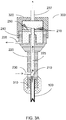
- FIG. 3A shows a cross-sectional view of a diagram of an apparatus 300 in accordance with further exemplary embodiments of the present disclosure.
- the apparatus 300 shown in FIG. 3A can be operated manually, and it has many features similar to those shown and described for the apparatus 200 in FIG. 2 , e.g., but not limited to, the housing 220 with the fluid conduit 225, the harvesting needle(s) 100, the fluid inlet 230, the outlet 235, the upper chamber 240, the optional vent 237, and the filter arrangement 250. Certain differences between the exemplary embodiments of the apparatus 200 illustrated in FIG. 2 and the apparatus shown in FIG. 3A are described herein.
- one or more of the harvesting needles 100 can be attached or affixed to a hub 310.
- the hub 310 can be provided, e.g., as a shaped disc or in another geometry with one or more harvesting needles 100 affixed to it.
- the hub 310 can be configured such that it can fit into a shaped recess in the housing 220, to facilitate removal and replacement of the harvesting needle(s) 100 during or between harvesting procedures.
- a protrusion distance of the harvesting needle(s) 100 beyond the bottom surface of the apparatus 300, which can correspond to a penetration depth of the needle(s) 100 into tissue, can be adjusted using an adjusting arrangement such as, e.g., a threaded screw coupler provided in the housing, or the like.
- one or more needles 100 can be provided with a hub 310, where a desired penetration depth of the needles 100 into the tissue of the donor site can be determined or selected based on a predetermined distance between the hub 310 and the distal end of the needle(s) 100.
- a hub 310 such as that shown in FIG. 3A , which can include one or more of the needles 100, can be used with any of the various exemplary embodiments described herein.
- the chamber 240 can be provided with a removable cap 320, or the like, to facilitate access to the interior of the chamber and removal of MTCs 210 that may be trapped or retained by the filter arrangement 250.
- the exemplary apparatus 300 can include the filter arrangement 250 provided in the chamber 240, where the filter arrangement 250 can be located between an end of the conduit 225 and the fluid outlet 235. Such configuration facilitates the flow of fluid containing the harvested MTCs 210 through the filter arrangement 250 and out of the outlet 235, where the MTCs 210 can be retained by the filter arrangement 250. Access to the MTCs 210 after they are harvested and trapped can be achieved, e.g., by removing the cap 320 from the chamber 240.
- the filter arrangement 250 and optionally the cap 320 can be provided, for example, as a sterile cartridge that can be inserted into the chamber 240 before harvesting MTCs 210, and can later be removed with the harvested MTCs 210.
- the filter arrangement 250 can be provided as a removable "basket” or the like that can be inserted into the chamber 240, and removed with trapped MTCs 210 after the harvesting procedure is completed.
- the exemplary apparatus 300 can be pressed onto a donor tissue site, such that the distal end of the harvesting needle 100 pierces the tissue and separates an MTC 210 from the surrounding tissue.
- the fluid flowing through the conduit 225 can facilitate withdrawal of the MTC 210 from the proximal end of the harvesting needle 100 such that it flows with the fluid through the conduit 225.
- the flowing fluid can transport the MTC 210 to the filter arrangement 250, where the MTC 210 can be retained by a mesh or other filter element, while the fluid flows through the filter arrangement 250 and exits the outlet 235, where it can optionally be recirculated.
- the apparatus 300 can be withdrawn from the donor site, and inserted into another location to harvest a further MTC 210. This process can be repeated a plurality of times to harvest a number of MTCs 210 from the donor site. After a sufficient number of MTCs 210 have been harvested, the filter arrangement 250 (or a portion thereof) containing the MTCs 210 can be removed from the apparatus 300 for further handling or processing.
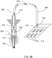
- FIG. 3B Another exemplary apparatus 350 is shown in FIG. 3B that can include several features in common with the other exemplary apparatuses 200, 300, e.g., the housing 220 with the fluid conduit 225, the harvesting needle(s) 100, and the fluid inlet 230.
- the exemplary apparatus 350 illustrated in FIG. 3B can be provided with a delivery arrangement 360 configured to direct at least a portion of the fluid flowing from the inlet 230 and through the conduit 225 onto a receiving substrate 370 (which can be or act as a filter arrangement).
- the delivery arrangement 360 can include rigid and/or flexible tubing, or the like, which can be connected to the conduit 225.
- the receiving substrate 370 can be or include, e.g., a filter element that can trap MTCs 210 while allowing fluid from the conduit 225 to flow through or off of the substrate 370.
- the substrate 370 can be or include a permeable or porous dressing material, which can act as a filter element to trap MTCs 210 thereon while allowing the fluid to pass through or flow off of the substrate 370.
- harvested MTCs 210 can be directly deposited onto a dressing or the like, and such dressing with the MTCs 210 can then be transported or applied directly to a wound site.
- the distal end of the delivery arrangement 360 can be positionable such that it traverses a predetermined region of the substrate 370 during the harvesting procedure, e.g., while fluid containing MTCs 210 flows through the conduit 225 and out of the distal end of the delivery arrangement 360.
- at least a portion of the delivery arrangement 360 can be flexible, such that the distal end thereof can be positioned and/or moved over the substrate 370 while the housing 220 containing the needle(s) 100 can be advanced and withdrawn over multiple locations of the donor site to harvest MTCs 210.
- the distal end of the delivery arrangement 360 can be held or maintained in a stationary position, and the substrate 370 can be controllably moved or translated relative to this distal end such that MTCs 210 are deposited over a predetermined area of the substrate 370.
- the translation of the distal end of the delivery arrangement 360 relative to the substrate 370 can be performed, e.g., using any one of various translation arrangements known in the art.
- Such positional translators can include, e.g., one or more motors or actuators, various arms, supports, clamps, pivots, or the like, along with any sensors and/or controllers that may be used to control a rate and/or direction of motion, limits of motion or displacement, etc.
- the relative motion of the distal end of the delivery arrangement 360 and the substrate 370 can be selected and/or performed such that MTCs 210 are deposited in a predetermined spacing, pattern or density on the substrate 370.
- the deposition geometry can be estimated in a straightforward manner based on the frequency at which the needle 100 is inserted into tissue to obtain a new MTC 210, together with the speed and direction of the relative motion between the distal end of the delivery arrangement 360 and the substrate 370.
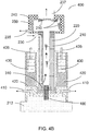
- FIGS. 4A and 4B another exemplary apparatus can be provided, is shown in FIGS. 4A and 4B that can include the harvesting needle(s) 100 secured to the hub 310.
- the apparatus 400 shown in FIGS. 4A and 4B has many features similar to those shown and described for the apparatus 200, 300 and/or 350 shown in FIG. 2 , FIG. 3A and FIG. 3B , respectively. These features include, e.g., the housing 220 with the fluid conduit 225, the harvesting needle(s) 100, the fluid inlet 230 and the outlet 235, the upper chamber 240, the vent 237, and the filter arrangement 250.
- One or more harvesting needles 100 can be attached or affixed to the hub 310.
- the exemplary apparatus 400 can include a base 420 that can be slidably engaged with the housing 220, e.g., such that the housing 220 can move up and down over a particular distance relative to the base 420.
- One or more solenoid coils 430 can be coupled or affixed to the base 420, and a solenoid core 435 can be located at least partially within the solenoid coil 430 and mechanically coupled to the housing 220.
- the solenoid(s) 430 can be configured to move the housing 220 and the attached needles 100 up and down relative to the base 420, thereby inserting and withdrawing the needles 100 from the donor tissue 212.
- One or more O-rings or similar sealing arrangements can be provided to maintain a fluid-tight seal between the housing 200 and the hub 310, and also between the housing 220 and the base 420 when the housing 220 is translated during operation of the apparatus 400.
- a linear bearing can optionally be provided to maintain support and alignment of the housing 220 within the base 420 during operation of the apparatus 400.
- the apparatus 400 of FIG. 4A shows the solenoids 430 which are not activated.
- the harvesting needles 100 are retracted so that they are close to but not protruding from, a lower surface of the base 420.
- the base 420 can be placed on the surface of the donor site tissue 212 to be harvested, with the solenoids 430 off, as shown in FIG. 4A .
- a pump arrangement or the like (not shown) can be activated to supply fluid to the inlet 230 and circulate it through the conduit 225, as described herein.
- the solenoids 430 can then be activated, such that the cores 435 are drawn downward, such that the housing 220 with mechanically coupled needles 110 are also pulled downward with respect to the base 420, as shown in FIG. 4B .
- This exemplary motion can result in the harvesting needles 100 protruding beyond a lower surface of the base 420, causing the needles 110 to pierce the tissue 212 of the donor site and separate MTCs 210 from the surrounding tissue 212, as described herein.
- the MTCs 210 can then be withdrawn from the needles 100 such that they flow through the conduit 225 with the fluid and can be deposited in the filter arrangement 250.
- the solenoids 430 can then be deactivated, such that the housing 220 rises relative to the base 420 (e.g., using springs or the like to return the housing to a raised position) and the needles 110 are withdrawn from the donor site 212 and back into the base 420, as shown in FIG. 4A .
- This exemplary procedure can be repeated at different locations on the donor site 212 to harvest additional MTCs 210.
- such apparatus 400 can be used to harvest the MTCs 210 at a frequency between about 0.5 and about 2 Hz, e.g., with a time interval between successive penetrations of about 0.5 to 2 seconds. Certain exemplary modifications may be developed to allow faster harvesting rates, and slower rates can also be used if desired.
- An adjusting arrangement such as, e.g., a screw-type adjuster or a spacer that can be attached to the base 420, can be provided to control the maximum protrusion length of the needles 110 from a lower surface of the base 420 (thereby controlling a corresponding maximum penetration depth of the needles 100 into the donor site tissue 212).
- actuators can be used instead of or in addition to the solenoids 430.
- one or more motors can be provided with a rotary/linear converter to convert rotary motion to a linear motion of the housing 220 relative to the base 420, e.g., at a controlled frequency and/or particular excursion distance.
- Other types of linear actuators can also be used to extend and withdraw the needles 100 from the tissue 212 beneath the apparatus 400.
- the base 420 of the exemplary apparatus 400 can be structured to include a recess 450 that can form an enclosed volume between the tissue surface 212 and a lower surface of the base 420 adjacent to the needles 100, as shown in FIG. 4A .
- exemplary recess 450 can be formed, e.g., by providing the base 420 with a rim or edge that can rest on the donor site tissue 212 while a lower surface of the base 420 remains a small distance above the tissue surface.
- One or more vacuum ducts 410 can be provided in communication with the enclosed volume. Application of a low-pressure or vacuum source (not shown) to the vacuum duct(s) 410 can cause the surface of the donor site tissue 212 to be pulled up into the recess 450, as shown in FIG.4B .
- This exemplary deformation can stretch the surface and provide tension, which may provide several benefits. For example, stretching the tissue surface can mechanically stabilize it such that the needles 100 can penetrate the stretched tissue 212 more easily than they may penetrate unstretched, resilient tissue. Further, puling the tissue surface upward using low pressure such that it contacts a lower surface of the base 420, as shown in FIG. 4B , can facilitate an accurate insertion depth of the needles 100. In certain embodiments, the needles 100 can be in a fixed position relative to the base 420 such that they remain protruding a small distance from the lower surface, as shown in FIG. 4B .
- the tissue 212 can be pulled up onto the needles 100 such that they pierce the tissue 212, as shown in FIG. 4B .
- the low pressure can then be released to allow the tissue 212 to relax and fall off the needles 110, optionally assisted with a positive pressure being applied to the vacuum ducts 410.
- An exemplary application of low (and/or optionally high) pressure to the vacuum ducts 410 can be done, for example, using a conventional pump arrangement or other source(s) of low and high pressure, together with an appropriate valve arrangements to control the application and release of pressure differences in the ducts 410.
- the timing of such pressure cycles can be coordinated with the activation/deactivation of the solenoids 430.
- Such exemplary chamber 450 with the vacuum ducts 410 can also be used with any of the other exemplary embodiments described herein.
- the surface of the donor site tissue 212 can be stretched or stabilized using other procedures, e.g., by manually stretching the surface with fingertips before inserting the needles 100.
- the donor site tissue 212 can be pre-cooled or partially frozen prior to insertion of the harvesting needles 100, e.g., using convective or conductive techniques such as a cryospray or contact with a cooled object.
- the exemplary cooling of the donor site tissue 212 can make it more rigid and facilitate insertion of the harvesting needles 100.
- a mechanical surface clamp or spreader can be applied around the donor site region to stretch the tissue 212 before inserting the needles 100. Such procedures can be performed with any of the exemplary devices and methods described herein.
- the exemplary apparatuses 200, 300, 350, 400 can be provided with various numbers of the harvesting needles 100.
- arrays of 4, 6, 8, 9, 12 or more of the needles 100 can be used, and they can be affixed to a hub 310 to facilitate insertion and removal of the needles 100 from the exemplary apparatuses 200, 300, 350, 400 as a group.
- the needles 100 can be provided in various geometrical arrangements such as, e.g., a square or triangular pattern.
- the hub arrangements can have between about 4 and 25 needles coupled thereto.
- the needles 100 can be spaced apart an appropriate distance to facilitate harvesting of a large number of the MTCs 210 from a donor site 212 while maintaining healthy tissue between the removed tissue samples 210 to promote rapid healing of the donor site 212, prevent formation of scars or markings, etc.
- the spacing between adjacent needles 100 can be about 1-2 mm, or up to about 5 mm. Larger spacings can be used in certain embodiments, but this can require a correspondingly larger width of the overall apparatus to accommodate the larger hub.
- the MTCs 210 can be harvested over a larger area of tissue 212 by moving the exemplary apparatuses 200, 300, 350, 400 to different locations before each needle insertion procedure.
- the exemplary embodiments described herein can include the fluid conduit 225 that is substantially vertical.
- other orientations of the conduit 225 can be provided.
- the conduit can be substantially horizontal, with the inlet 230 and the outlet 235 can be provided at opposing ends of such a conduit 225, and the proximal ends of the needles 100 protruding into the conduit 225 such that the liquid flows past this end of the needles 100.
- Such an exemplary configuration can also provide a simpler, e.g. linear, conduit geometry that may be easier to manufacture and/or clean, may result in fewer pressure drops along the fluid path, etc.
- Other exemplary orientations of the conduit 225 or shapes thereof, such as a curved conduit can also be provided in still further exemplary embodiments of the present disclosure.
- At least two of the needles 100 can be separately actuated, e.g., such that they pierce the tissue 212 at different times.
- two or more actuators can be coupled to different ones of the needles.
- a singular actuator can be provided that is configured to advance different ones of the needles at different times. Such 'staggering' of penetrations can reduce the maximum force needed to advance the needles into the tissue.
- needle cross-sectional shapes can be used with the various embodiments described herein to harvest the MTCs 210 having different geometric characteristics. Although circular cross-sections are most common, needles 100 having oval, square, or triangular cross-sections, or combinations thereof in multi-needle devices, can also be used.
- the exemplary methods and apparatus described herein can be applied to other tissues besides skin tissue.
- the MTCs 210 can be harvested from a variety of organs or tissue structures, which can facilitate rapid healing of a donor site while providing microscopic graft tissue suitable for placement at recipient sites, on scaffolds, within biocompatible matrices, etc.
Claims (15)
- Appareil (200) pour obtenir au moins une portion d'un tissu biologique, comprenant :au moins un tube creux (100) ayant un diamètre interne inférieur à environ 1 mm ;un conduit (225) configuré pour faciliter l'écoulement d'un fluide à travers celui-ci, dans lequel une extrémité proximale de l'au moins un tube creux est en communication avec le conduit ;au moins un évent (237) prévu en communication fluidique avec le conduit (225), dans lequel l'au moins un évent (237) est configuré pour faciliter le retrait d'un gaz du fluide ; etun agencement de filtre (250) prévu au moins partiellement sur un trajet du fluide,dans lequel une portion distale d'au moins un tube creux (100) est structurée pour être insérée, dans l'au moins un tissu biologique pour retirer l'au moins une portion de celui-ci lorsque l'au moins un tube (100) est extrait du tissu biologique, etdans lequel, en fonctionnement, le fluide s'écoule à travers le conduit (225) de façon à retirer l'au moins une portion de l'au moins un tube creux (100), et transporter l'au moins une portion jusqu'à l'agencement de filtre (250).
- Appareil (200) selon la revendication 1, dans lequel l'au moins une portion d'un tissu biologique est un tissu cutané.
- Appareil (200) selon la revendication 1, dans lequel l'au moins un tube creux (100) comprend au moins deux agencements de perforation (105) prévus à une extrémité distale de celui-ci.
- Appareil selon la revendication 1, comprenant en outre un système de commande thermique en communication avec le fluide et configuré pour commander une température de fluide.
- Appareil (200) selon la revendication 1, comprenant en outre au moins un capteur en communication avec un dispositif de commande, dans lequel l'au moins un capteur est configuré pour fournir, au dispositif de commande, un paramètre indicatif d'un débit du fluide à travers le conduit.
- Appareil (200) selon la revendication 5, dans lequel le dispositif de commande est configuré pour commander le débit du fluide à travers le conduit, d'après le paramètre.
- Appareil (200) selon la revendication 1, comprenant en outre au moins un capteur en communication avec un dispositif de commande, dans lequel l'au moins un capteur est configuré pour fournir, au dispositif de commande, un paramètre indicatif d'une composition du fluide.
- Appareil (200) selon la revendication 7, dans lequel le dispositif de commande est configuré pour commander la composition du fluide, d'après le paramètre, dans lequel la composition comprend au moins l'un parmi une solution saline, des facteurs de croissance ou des tampons.
- Appareil (200) selon la revendication 1, dans lequel l'agencement de filtre comprend au moins un élément de filtre configuré pour séparer l'au moins une portion du tissu biologique du fluide.
- Appareil (200) selon la revendication 9, dans lequel l'au moins un élément de filtre (250) est un panier à mailles.
- Appareil (200) selon la revendication 1, comprenant en outre un boîtier (220), dans lequel le conduit (225) passe au moins partiellement à travers le boîtier (220), et dans lequel l'au moins un tube creux (100) est couplé au boîtier.
- Appareil (200) selon la revendication 11, comprenant en outre une base (420) configurée pour être placée sur une surface du tissu biologique.
- Appareil (200) selon la revendication 12, dans lequel la base comprend au moins un canal (410) et est configurée pour former un volume clos au-dessus d'une surface du tissu biologique, dans lequel la surface du tissu biologique peut être étirée lorsqu'une source de basse pression est raccordée à l'au moins un canal (410) pour produire une pression réduite au sein du volume clos.
- Appareil (200) selon la revendication 12, dans lequel la base (420) est couplée de façon mobile au boîtier (220) suivant un axe, dans lequel la base (420) est configurée pour être placée sur une surface du tissu biologique, et dans lequel le boîtier (220) est configuré pour insérer l'au moins un tube creux (100) dans le tissu biologique et le retirer de celui-ci lorsque le boîtier (220) est amené à effectuer une translation en arrière et en avant suivant l'axe par rapport à la base (420) .
- Appareil (200) selon la revendication 14, comprenant en outre un agencement d'actionneur configuré pour effectuer une translation du boîtier (220) par rapport à la base (420).
Priority Applications (1)
| Application Number | Priority Date | Filing Date | Title |
|---|---|---|---|
| EP22150983.9A EP4005499A1 (fr) | 2012-08-14 | 2013-08-14 | Appareil de collecte de tissus |
Applications Claiming Priority (3)
| Application Number | Priority Date | Filing Date | Title |
|---|---|---|---|
| US201261682969P | 2012-08-14 | 2012-08-14 | |
| EP13829700.7A EP2890304B1 (fr) | 2012-08-14 | 2013-08-14 | Appareil de prelevement de tissu |
| PCT/US2013/054955 WO2014028626A1 (fr) | 2012-08-14 | 2013-08-14 | Procédé et appareil de récolte de tissu |
Related Parent Applications (1)
| Application Number | Title | Priority Date | Filing Date |
|---|---|---|---|
| EP13829700.7A Division EP2890304B1 (fr) | 2012-08-14 | 2013-08-14 | Appareil de prelevement de tissu |
Related Child Applications (1)
| Application Number | Title | Priority Date | Filing Date |
|---|---|---|---|
| EP22150983.9A Division EP4005499A1 (fr) | 2012-08-14 | 2013-08-14 | Appareil de collecte de tissus |
Publications (2)
| Publication Number | Publication Date |
|---|---|
| EP3563772A1 EP3563772A1 (fr) | 2019-11-06 |
| EP3563772B1 true EP3563772B1 (fr) | 2022-01-12 |
Family
ID=50101475
Family Applications (3)
| Application Number | Title | Priority Date | Filing Date |
|---|---|---|---|
| EP22150983.9A Pending EP4005499A1 (fr) | 2012-08-14 | 2013-08-14 | Appareil de collecte de tissus |
| EP13829700.7A Active EP2890304B1 (fr) | 2012-08-14 | 2013-08-14 | Appareil de prelevement de tissu |
| EP19182350.9A Active EP3563772B1 (fr) | 2012-08-14 | 2013-08-14 | Appareil de collecte de tissus |
Family Applications Before (2)
| Application Number | Title | Priority Date | Filing Date |
|---|---|---|---|
| EP22150983.9A Pending EP4005499A1 (fr) | 2012-08-14 | 2013-08-14 | Appareil de collecte de tissus |
| EP13829700.7A Active EP2890304B1 (fr) | 2012-08-14 | 2013-08-14 | Appareil de prelevement de tissu |
Country Status (6)
| Country | Link |
|---|---|
| US (2) | US11717317B2 (fr) |
| EP (3) | EP4005499A1 (fr) |
| AU (2) | AU2013302673B2 (fr) |
| CA (2) | CA3151257A1 (fr) |
| HK (1) | HK1211818A1 (fr) |
| WO (1) | WO2014028626A1 (fr) |
Families Citing this family (39)
| Publication number | Priority date | Publication date | Assignee | Title |
|---|---|---|---|---|
| WO2011075676A2 (fr) | 2009-12-18 | 2011-06-23 | Knowlton Edward W | Dispositif d'administration de médicament et de traitement de la peau |
| US11278309B2 (en) | 2010-12-17 | 2022-03-22 | Srgi Holdings, Llc | Pixel array medical systems, devices and methods |
| US10736653B2 (en) | 2013-12-06 | 2020-08-11 | Srgi Holdings, Llc | Pixel array medical systems, devices and methods |
| US11000310B2 (en) | 2010-12-17 | 2021-05-11 | Srgi Holdings, Llc | Pixel array medical systems, devices and methods |
| US10905865B2 (en) | 2010-12-17 | 2021-02-02 | Srgi Holdings, Llc | Systems, devices and methods for fractional resection, fractional skin grafting, fractional scar reduction and fractional tattoo removal |
| US11109887B2 (en) * | 2013-12-06 | 2021-09-07 | Srgi Holdings, Llc | Pixel array medical systems, devices and methods |
| US11103275B2 (en) | 2010-12-17 | 2021-08-31 | Srgi Holdings, Llc | Pixel array medical systems, devices and methods |
| US10856900B2 (en) | 2010-12-17 | 2020-12-08 | Srgi Holdings, Llc | Pixel array medical systems, devices and methods |
| US10314640B2 (en) | 2010-12-17 | 2019-06-11 | Srgi Holdings, Llc | Pixel array medical devices and methods |
| US10702684B2 (en) | 2010-12-17 | 2020-07-07 | Srgi Holdings, Llc | Systems, devices and methods for fractional resection, fractional skin grafting, fractional scar reduction and fractional tattoo removal |
| CA2894280C (fr) | 2012-12-06 | 2018-07-31 | Srgi Holdings Llc | Dispositifs medicaux a reseau de pixels et procedes |
| WO2014130359A1 (fr) | 2013-02-20 | 2014-08-28 | Cytrellis Biosystems, Inc. | Procédés et dispositifs pour le resserrement de la peau |
| ES2827049T3 (es) | 2013-10-02 | 2021-05-19 | Srgi Holdings Llc | Dispositivos médicos de conjunto de píxeles |
| CN105828731A (zh) | 2013-10-02 | 2016-08-03 | Srgi控股有限责任公司 | 像素阵列式医疗设备及方法 |
| US11229452B2 (en) | 2013-12-06 | 2022-01-25 | Srgi Holdings, Llc | Pixel array medical systems, devices and methods |
| US11937846B2 (en) | 2013-12-06 | 2024-03-26 | Srgi Holdings Llc | Pixel array medical systems, devices and methods |
| US20170296214A1 (en) | 2013-12-06 | 2017-10-19 | Edward KNOWLTON | Pixel array medical systems, devices and methods |
| WO2015116954A1 (fr) * | 2014-01-31 | 2015-08-06 | University Of Massachusetts Medical School | Dispositif de microbiopsie amélioré |
| US10448968B2 (en) * | 2014-02-26 | 2019-10-22 | Infuez, Llc | Follicle extraction system and related methods |
| US11065027B2 (en) | 2014-07-15 | 2021-07-20 | The General Hospital Corporation | Method and apparatus for tissue copying and grafting |
| JP2020116398A (ja) * | 2014-08-29 | 2020-08-06 | エスアールジーアイ ホールディングス エルエルシーSrgi Holdings Llc | ピクセルアレイ医療デバイスおよび方法 |
| BR112017004112A2 (pt) * | 2014-08-29 | 2017-12-05 | Srgi Holdings Llc | dispositivos médicos de arranjo em pixel e métodos |
| JP2017533774A (ja) | 2014-11-14 | 2017-11-16 | サイトレリス バイオシステムズ,インコーポレーテッド | 皮膚のアブレーションのためのデバイス及び方法 |
| EP3253308A4 (fr) * | 2015-02-05 | 2018-10-24 | SRGI Holdings LLC | Systèmes, dispositifs et procédés médicaux à réseau de pixels |
| US10478212B2 (en) | 2015-04-22 | 2019-11-19 | Medline Industries, Inc. | Method and system for harvesting biological tissue |
| US11759231B2 (en) | 2015-08-31 | 2023-09-19 | Srgi Holdings, Llc | Pixel array medical systems, devices and methods |
| US11490952B2 (en) | 2015-08-31 | 2022-11-08 | Srgi Holdings, Llc | Pixel array medical devices and methods |
| SE541418C2 (en) * | 2016-01-22 | 2019-09-24 | S2Medical Ab | Minimally invasive tissue harvesting device |
| US11564706B2 (en) | 2019-10-28 | 2023-01-31 | Srgi Holdings, Llc | Pixel array medical systems, devices and methods |
| US20210085356A1 (en) * | 2016-02-05 | 2021-03-25 | Srgi Holdings, Llc | Pixel array medical systems, devices and methods |
| JP2019506235A (ja) * | 2016-02-11 | 2019-03-07 | エスアールジーアイ ホールディングス エルエルシーSrgi Holdings Llc | ピクセルアレイ医療システム、デバイスおよび方法 |
| CN109922740B (zh) | 2016-09-21 | 2022-08-23 | 希特利斯生物系统有限公司 | 用于美容皮肤重建的装置和方法 |
| EP4162886A1 (fr) | 2016-10-28 | 2023-04-12 | The General Hospital Corporation | Procédés d'assemblage de greffons tissulaires |
| WO2020086915A2 (fr) * | 2017-05-03 | 2020-04-30 | Srgi Holdings Llc | Réseau de scalpels à fentes en spirale à main |
| WO2018217479A2 (fr) | 2017-05-11 | 2018-11-29 | Srgi Holdings, Llc | Systèmes, dispositifs et procédés de résection fractionnellee, de greffe de peau fractionnelle, de réduction de cicatrice fractionnée et d'élimination de tatouage fractionnelle |
| US20190000428A1 (en) * | 2017-06-30 | 2019-01-03 | Boston Scientific Scimed, Inc. | Aspiration filtration device |
| CN107961061A (zh) * | 2017-12-19 | 2018-04-27 | 济南磐升生物技术有限公司 | 一种自体皮肤创伤治疗仪 |
| US11369409B2 (en) * | 2019-10-03 | 2022-06-28 | Medline Industries, Lp | System and method for fluid ingress control for a skin grafting system |
| US11633208B2 (en) * | 2020-01-13 | 2023-04-25 | Medline Industries, Lp | System and method for clinical soil control for a skin grafting system |
Citations (1)
| Publication number | Priority date | Publication date | Assignee | Title |
|---|---|---|---|---|
| US20110313429A1 (en) * | 2010-05-07 | 2011-12-22 | The General Hospital Corporation | Method and apparatus for tissue grafting and copying |
Family Cites Families (31)
| Publication number | Priority date | Publication date | Assignee | Title |
|---|---|---|---|---|
| US4930997A (en) * | 1987-08-19 | 1990-06-05 | Bennett Alan N | Portable medical suction device |
| WO1998029149A1 (fr) * | 1997-01-03 | 1998-07-09 | Shettigar U Ramakrishna | Systeme peroperatoire de recuperation de sang et procede afferent |
| US6027512A (en) * | 1998-05-28 | 2000-02-22 | Bridges; Ronzee M. | Hair follicle harvesting device |
| DE10054621A1 (de) | 1999-11-19 | 2001-05-23 | Leica Mikrosysteme Ag Wien | Biopsienadel |
| US6537242B1 (en) * | 2000-06-06 | 2003-03-25 | Becton, Dickinson And Company | Method and apparatus for enhancing penetration of a member for the intradermal sampling or administration of a substance |
| US7651507B2 (en) | 2003-03-03 | 2010-01-26 | Kci Licensing, Inc. | Tissue processing system |
| US7364565B2 (en) * | 2001-07-27 | 2008-04-29 | Ramot At Tel Aviv University Ltd. | Controlled enzymatic removal and retrieval of cells |
| US6881203B2 (en) | 2001-09-05 | 2005-04-19 | 3M Innovative Properties Company | Microneedle arrays and methods of manufacturing the same |
| US20040175690A1 (en) | 2003-03-03 | 2004-09-09 | Kci Licensing, Inc. | Tissue harvesting device and method |
| AU2004251699A1 (en) * | 2003-06-04 | 2005-01-06 | Georgia Tech Research Corporation | Drilling microneedle device |
| US8753354B2 (en) * | 2004-03-09 | 2014-06-17 | John P. Cole | Enhanced follicular extraction punch and method |
| US7717274B2 (en) | 2004-06-09 | 2010-05-18 | The Board Of Supervisors Of Louisiana State University And Agricultural And Mechanical College | Device and method for preparing washed red blood cells for newborn transfusions |
| US10035008B2 (en) | 2005-04-07 | 2018-07-31 | 3M Innovative Properties Company | System and method for tool feedback sensing |
| US7662109B2 (en) * | 2006-02-01 | 2010-02-16 | Ethicon Endo-Surgery, Inc. | Biopsy device with replaceable probe incorporating static vacuum source dual valve sample stacking retrieval and saline flush |
| US9119945B2 (en) | 2006-04-20 | 2015-09-01 | 3M Innovative Properties Company | Device for applying a microneedle array |
| US8066717B2 (en) | 2007-03-19 | 2011-11-29 | Restoration Robotics, Inc. | Device and method for harvesting and implanting follicular units |
| WO2008124650A1 (fr) * | 2007-04-06 | 2008-10-16 | Interlace Medical, Inc. | Procédé, système et dispositif d'exérèse de tissu |
| US8226664B2 (en) | 2008-03-18 | 2012-07-24 | Restoration Robotics, Inc. | Biological unit removal tools with movable retention member |
| EP2265197B1 (fr) * | 2008-04-01 | 2021-03-24 | The General Hospital Corporation | Appareil pour greffer du tissu |
| US8388631B2 (en) * | 2009-01-23 | 2013-03-05 | Restoration Robotics, Inc. | Skin tensioner for hair transplantation |
| ES2830201T3 (es) * | 2010-07-27 | 2021-06-03 | Pave Llc | Dispositivo de biopsia de núcleo completo |
| CN102791208B (zh) * | 2010-07-30 | 2015-02-25 | 奥林巴斯医疗株式会社 | 医疗用针以及医疗器具 |
| ES2718651T3 (es) * | 2011-01-28 | 2019-07-03 | Massachusetts Gen Hospital | Método y aparato para dermoabrasión discontinua |
| WO2012103483A2 (fr) | 2011-01-28 | 2012-08-02 | The General Hospital Corporation | Appareil et procédé pour biopsie de tissus |
| US9439673B2 (en) * | 2011-01-28 | 2016-09-13 | The General Hospital Corporation | Method and apparatus for skin resurfacing |
| US9468459B2 (en) | 2011-04-20 | 2016-10-18 | Kci Licensing, Inc. | Skin graft devices and methods |
| WO2014058746A1 (fr) | 2012-10-10 | 2014-04-17 | 3M Innovative Properties Company | Applicateur régulé par une force pour appliquer un dispositif à micro-aiguille sur la peau |
| KR102236575B1 (ko) | 2012-12-21 | 2021-04-05 | 쓰리엠 이노베이티브 프로퍼티즈 컴파니 | 접착제 조립체 및 이를 포함하는 마이크로니들 주사 장치 |
| SG11201509722PA (en) | 2013-05-31 | 2015-12-30 | 3M Innovative Properties Co | Microneedle injection apparatus comprising a dual cover |
| US9682222B2 (en) | 2013-05-31 | 2017-06-20 | 3M Innovative Properties Company | Microneedle injection apparatus comprising an inverted actuator |
| US10232157B2 (en) | 2013-07-16 | 2019-03-19 | 3M Innovative Properties Company | Hollow microneedle with beveled tip |
-
2013
- 2013-08-14 CA CA3151257A patent/CA3151257A1/fr active Pending
- 2013-08-14 EP EP22150983.9A patent/EP4005499A1/fr active Pending
- 2013-08-14 AU AU2013302673A patent/AU2013302673B2/en active Active
- 2013-08-14 CA CA2882129A patent/CA2882129C/fr active Active
- 2013-08-14 EP EP13829700.7A patent/EP2890304B1/fr active Active
- 2013-08-14 EP EP19182350.9A patent/EP3563772B1/fr active Active
- 2013-08-14 WO PCT/US2013/054955 patent/WO2014028626A1/fr active Application Filing
- 2013-08-14 US US14/421,592 patent/US11717317B2/en active Active
-
2015
- 2015-12-23 HK HK15112627.9A patent/HK1211818A1/xx unknown
-
2018
- 2018-03-20 AU AU2018201959A patent/AU2018201959B2/en active Active
-
2023
- 2023-06-27 US US18/328,396 patent/US20230414249A1/en active Pending
Patent Citations (1)
| Publication number | Priority date | Publication date | Assignee | Title |
|---|---|---|---|---|
| US20110313429A1 (en) * | 2010-05-07 | 2011-12-22 | The General Hospital Corporation | Method and apparatus for tissue grafting and copying |
Also Published As
| Publication number | Publication date |
|---|---|
| EP2890304A1 (fr) | 2015-07-08 |
| US20150216545A1 (en) | 2015-08-06 |
| EP2890304B1 (fr) | 2019-06-26 |
| AU2018201959A1 (en) | 2018-04-26 |
| EP4005499A1 (fr) | 2022-06-01 |
| AU2018201959B2 (en) | 2020-02-13 |
| CA2882129C (fr) | 2022-06-21 |
| US20230414249A1 (en) | 2023-12-28 |
| AU2013302673A1 (en) | 2015-04-02 |
| US11717317B2 (en) | 2023-08-08 |
| WO2014028626A1 (fr) | 2014-02-20 |
| CA3151257A1 (fr) | 2014-02-20 |
| AU2013302673B2 (en) | 2017-12-21 |
| EP3563772A1 (fr) | 2019-11-06 |
| HK1211818A1 (en) | 2016-06-03 |
| CA2882129A1 (fr) | 2014-02-20 |
| EP2890304A4 (fr) | 2016-06-22 |
Similar Documents
| Publication | Publication Date | Title |
|---|---|---|
| US20230414249A1 (en) | Method and apparatus for tissue harvesting | |
| US11832845B2 (en) | Method and apparatus for tissue grafting and copying | |
| US20210145476A1 (en) | Systems and methods for hair transplant | |
| JP7235876B2 (ja) | グラフト移植器具に毛髪グラフトを装填するための装置 |
Legal Events
| Date | Code | Title | Description |
|---|---|---|---|
| PUAI | Public reference made under article 153(3) epc to a published international application that has entered the european phase |
Free format text: ORIGINAL CODE: 0009012 |
|
| STAA | Information on the status of an ep patent application or granted ep patent |
Free format text: STATUS: THE APPLICATION HAS BEEN PUBLISHED |
|
| AC | Divisional application: reference to earlier application |
Ref document number: 2890304 Country of ref document: EP Kind code of ref document: P |
|
| AK | Designated contracting states |
Kind code of ref document: A1 Designated state(s): AL AT BE BG CH CY CZ DE DK EE ES FI FR GB GR HR HU IE IS IT LI LT LU LV MC MK MT NL NO PL PT RO RS SE SI SK SM TR |
|
| STAA | Information on the status of an ep patent application or granted ep patent |
Free format text: STATUS: REQUEST FOR EXAMINATION WAS MADE |
|
| 17P | Request for examination filed |
Effective date: 20200505 |
|
| RBV | Designated contracting states (corrected) |
Designated state(s): AL AT BE BG CH CY CZ DE DK EE ES FI FR GB GR HR HU IE IS IT LI LT LU LV MC MK MT NL NO PL PT RO RS SE SI SK SM TR |
|
| STAA | Information on the status of an ep patent application or granted ep patent |
Free format text: STATUS: EXAMINATION IS IN PROGRESS |
|
| 17Q | First examination report despatched |
Effective date: 20200827 |
|
| STAA | Information on the status of an ep patent application or granted ep patent |
Free format text: STATUS: EXAMINATION IS IN PROGRESS |
|
| RIC1 | Information provided on ipc code assigned before grant |
Ipc: A61B 10/02 20060101AFI20210624BHEP Ipc: A61B 17/34 20060101ALI20210624BHEP Ipc: A61B 17/00 20060101ALI20210624BHEP Ipc: A61B 17/322 20060101ALI20210624BHEP |
|
| GRAP | Despatch of communication of intention to grant a patent |
Free format text: ORIGINAL CODE: EPIDOSNIGR1 |
|
| STAA | Information on the status of an ep patent application or granted ep patent |
Free format text: STATUS: GRANT OF PATENT IS INTENDED |
|
| INTG | Intention to grant announced |
Effective date: 20210803 |
|
| GRAS | Grant fee paid |
Free format text: ORIGINAL CODE: EPIDOSNIGR3 |
|
| GRAA | (expected) grant |
Free format text: ORIGINAL CODE: 0009210 |
|
| STAA | Information on the status of an ep patent application or granted ep patent |
Free format text: STATUS: THE PATENT HAS BEEN GRANTED |
|
| AC | Divisional application: reference to earlier application |
Ref document number: 2890304 Country of ref document: EP Kind code of ref document: P |
|
| AK | Designated contracting states |
Kind code of ref document: B1 Designated state(s): AL AT BE BG CH CY CZ DE DK EE ES FI FR GB GR HR HU IE IS IT LI LT LU LV MC MK MT NL NO PL PT RO RS SE SI SK SM TR |
|
| REG | Reference to a national code |
Ref country code: GB Ref legal event code: FG4D |
|
| REG | Reference to a national code |
Ref country code: CH Ref legal event code: EP |
|
| REG | Reference to a national code |
Ref country code: DE Ref legal event code: R096 Ref document number: 602013080711 Country of ref document: DE |
|
| REG | Reference to a national code |
Ref country code: IE Ref legal event code: FG4D |
|
| REG | Reference to a national code |
Ref country code: AT Ref legal event code: REF Ref document number: 1461865 Country of ref document: AT Kind code of ref document: T Effective date: 20220215 |
|
| REG | Reference to a national code |
Ref country code: NL Ref legal event code: FP |
|
| REG | Reference to a national code |
Ref country code: LT Ref legal event code: MG9D |
|
| REG | Reference to a national code |
Ref country code: AT Ref legal event code: MK05 Ref document number: 1461865 Country of ref document: AT Kind code of ref document: T Effective date: 20220112 |
|
| PG25 | Lapsed in a contracting state [announced via postgrant information from national office to epo] |
Ref country code: SE Free format text: LAPSE BECAUSE OF FAILURE TO SUBMIT A TRANSLATION OF THE DESCRIPTION OR TO PAY THE FEE WITHIN THE PRESCRIBED TIME-LIMIT Effective date: 20220112 Ref country code: RS Free format text: LAPSE BECAUSE OF FAILURE TO SUBMIT A TRANSLATION OF THE DESCRIPTION OR TO PAY THE FEE WITHIN THE PRESCRIBED TIME-LIMIT Effective date: 20220112 Ref country code: PT Free format text: LAPSE BECAUSE OF FAILURE TO SUBMIT A TRANSLATION OF THE DESCRIPTION OR TO PAY THE FEE WITHIN THE PRESCRIBED TIME-LIMIT Effective date: 20220512 Ref country code: NO Free format text: LAPSE BECAUSE OF FAILURE TO SUBMIT A TRANSLATION OF THE DESCRIPTION OR TO PAY THE FEE WITHIN THE PRESCRIBED TIME-LIMIT Effective date: 20220412 Ref country code: LT Free format text: LAPSE BECAUSE OF FAILURE TO SUBMIT A TRANSLATION OF THE DESCRIPTION OR TO PAY THE FEE WITHIN THE PRESCRIBED TIME-LIMIT Effective date: 20220112 Ref country code: HR Free format text: LAPSE BECAUSE OF FAILURE TO SUBMIT A TRANSLATION OF THE DESCRIPTION OR TO PAY THE FEE WITHIN THE PRESCRIBED TIME-LIMIT Effective date: 20220112 Ref country code: ES Free format text: LAPSE BECAUSE OF FAILURE TO SUBMIT A TRANSLATION OF THE DESCRIPTION OR TO PAY THE FEE WITHIN THE PRESCRIBED TIME-LIMIT Effective date: 20220112 Ref country code: BG Free format text: LAPSE BECAUSE OF FAILURE TO SUBMIT A TRANSLATION OF THE DESCRIPTION OR TO PAY THE FEE WITHIN THE PRESCRIBED TIME-LIMIT Effective date: 20220412 |
|
| PG25 | Lapsed in a contracting state [announced via postgrant information from national office to epo] |
Ref country code: PL Free format text: LAPSE BECAUSE OF FAILURE TO SUBMIT A TRANSLATION OF THE DESCRIPTION OR TO PAY THE FEE WITHIN THE PRESCRIBED TIME-LIMIT Effective date: 20220112 Ref country code: LV Free format text: LAPSE BECAUSE OF FAILURE TO SUBMIT A TRANSLATION OF THE DESCRIPTION OR TO PAY THE FEE WITHIN THE PRESCRIBED TIME-LIMIT Effective date: 20220112 Ref country code: GR Free format text: LAPSE BECAUSE OF FAILURE TO SUBMIT A TRANSLATION OF THE DESCRIPTION OR TO PAY THE FEE WITHIN THE PRESCRIBED TIME-LIMIT Effective date: 20220413 Ref country code: FI Free format text: LAPSE BECAUSE OF FAILURE TO SUBMIT A TRANSLATION OF THE DESCRIPTION OR TO PAY THE FEE WITHIN THE PRESCRIBED TIME-LIMIT Effective date: 20220112 Ref country code: AT Free format text: LAPSE BECAUSE OF FAILURE TO SUBMIT A TRANSLATION OF THE DESCRIPTION OR TO PAY THE FEE WITHIN THE PRESCRIBED TIME-LIMIT Effective date: 20220112 |
|
| PG25 | Lapsed in a contracting state [announced via postgrant information from national office to epo] |
Ref country code: IS Free format text: LAPSE BECAUSE OF FAILURE TO SUBMIT A TRANSLATION OF THE DESCRIPTION OR TO PAY THE FEE WITHIN THE PRESCRIBED TIME-LIMIT Effective date: 20220512 |
|
| REG | Reference to a national code |
Ref country code: DE Ref legal event code: R097 Ref document number: 602013080711 Country of ref document: DE |
|
| PG25 | Lapsed in a contracting state [announced via postgrant information from national office to epo] |
Ref country code: SM Free format text: LAPSE BECAUSE OF FAILURE TO SUBMIT A TRANSLATION OF THE DESCRIPTION OR TO PAY THE FEE WITHIN THE PRESCRIBED TIME-LIMIT Effective date: 20220112 Ref country code: SK Free format text: LAPSE BECAUSE OF FAILURE TO SUBMIT A TRANSLATION OF THE DESCRIPTION OR TO PAY THE FEE WITHIN THE PRESCRIBED TIME-LIMIT Effective date: 20220112 Ref country code: RO Free format text: LAPSE BECAUSE OF FAILURE TO SUBMIT A TRANSLATION OF THE DESCRIPTION OR TO PAY THE FEE WITHIN THE PRESCRIBED TIME-LIMIT Effective date: 20220112 Ref country code: EE Free format text: LAPSE BECAUSE OF FAILURE TO SUBMIT A TRANSLATION OF THE DESCRIPTION OR TO PAY THE FEE WITHIN THE PRESCRIBED TIME-LIMIT Effective date: 20220112 Ref country code: DK Free format text: LAPSE BECAUSE OF FAILURE TO SUBMIT A TRANSLATION OF THE DESCRIPTION OR TO PAY THE FEE WITHIN THE PRESCRIBED TIME-LIMIT Effective date: 20220112 Ref country code: CZ Free format text: LAPSE BECAUSE OF FAILURE TO SUBMIT A TRANSLATION OF THE DESCRIPTION OR TO PAY THE FEE WITHIN THE PRESCRIBED TIME-LIMIT Effective date: 20220112 |
|
| PLBE | No opposition filed within time limit |
Free format text: ORIGINAL CODE: 0009261 |
|
| STAA | Information on the status of an ep patent application or granted ep patent |
Free format text: STATUS: NO OPPOSITION FILED WITHIN TIME LIMIT |
|
| PG25 | Lapsed in a contracting state [announced via postgrant information from national office to epo] |
Ref country code: AL Free format text: LAPSE BECAUSE OF FAILURE TO SUBMIT A TRANSLATION OF THE DESCRIPTION OR TO PAY THE FEE WITHIN THE PRESCRIBED TIME-LIMIT Effective date: 20220112 |
|
| 26N | No opposition filed |
Effective date: 20221013 |
|
| PG25 | Lapsed in a contracting state [announced via postgrant information from national office to epo] |
Ref country code: SI Free format text: LAPSE BECAUSE OF FAILURE TO SUBMIT A TRANSLATION OF THE DESCRIPTION OR TO PAY THE FEE WITHIN THE PRESCRIBED TIME-LIMIT Effective date: 20220112 |
|
| PG25 | Lapsed in a contracting state [announced via postgrant information from national office to epo] |
Ref country code: MC Free format text: LAPSE BECAUSE OF FAILURE TO SUBMIT A TRANSLATION OF THE DESCRIPTION OR TO PAY THE FEE WITHIN THE PRESCRIBED TIME-LIMIT Effective date: 20220112 |
|
| REG | Reference to a national code |
Ref country code: CH Ref legal event code: PL |
|
| GBPC | Gb: european patent ceased through non-payment of renewal fee |
Effective date: 20220814 |
|
| PG25 | Lapsed in a contracting state [announced via postgrant information from national office to epo] |
Ref country code: LU Free format text: LAPSE BECAUSE OF NON-PAYMENT OF DUE FEES Effective date: 20220814 Ref country code: LI Free format text: LAPSE BECAUSE OF NON-PAYMENT OF DUE FEES Effective date: 20220831 Ref country code: CH Free format text: LAPSE BECAUSE OF NON-PAYMENT OF DUE FEES Effective date: 20220831 |
|
| REG | Reference to a national code |
Ref country code: BE Ref legal event code: MM Effective date: 20220831 |
|
| P01 | Opt-out of the competence of the unified patent court (upc) registered |
Effective date: 20230526 |
|
| PG25 | Lapsed in a contracting state [announced via postgrant information from national office to epo] |
Ref country code: IT Free format text: LAPSE BECAUSE OF FAILURE TO SUBMIT A TRANSLATION OF THE DESCRIPTION OR TO PAY THE FEE WITHIN THE PRESCRIBED TIME-LIMIT Effective date: 20220112 Ref country code: IE Free format text: LAPSE BECAUSE OF NON-PAYMENT OF DUE FEES Effective date: 20220814 Ref country code: FR Free format text: LAPSE BECAUSE OF NON-PAYMENT OF DUE FEES Effective date: 20220831 |
|
| PG25 | Lapsed in a contracting state [announced via postgrant information from national office to epo] |
Ref country code: BE Free format text: LAPSE BECAUSE OF NON-PAYMENT OF DUE FEES Effective date: 20220831 |
|
| PGFP | Annual fee paid to national office [announced via postgrant information from national office to epo] |
Ref country code: NL Payment date: 20230826 Year of fee payment: 11 |
|
| PG25 | Lapsed in a contracting state [announced via postgrant information from national office to epo] |
Ref country code: GB Free format text: LAPSE BECAUSE OF NON-PAYMENT OF DUE FEES Effective date: 20220814 |
|
| PGFP | Annual fee paid to national office [announced via postgrant information from national office to epo] |
Ref country code: DE Payment date: 20230829 Year of fee payment: 11 |
|
| PG25 | Lapsed in a contracting state [announced via postgrant information from national office to epo] |
Ref country code: HU Free format text: LAPSE BECAUSE OF FAILURE TO SUBMIT A TRANSLATION OF THE DESCRIPTION OR TO PAY THE FEE WITHIN THE PRESCRIBED TIME-LIMIT; INVALID AB INITIO Effective date: 20130814 |