EP3563109B1 - Wärmeübertragungsfolienanordnung mit zwischenräumen - Google Patents
Wärmeübertragungsfolienanordnung mit zwischenräumen Download PDFInfo
- Publication number
- EP3563109B1 EP3563109B1 EP17719115.2A EP17719115A EP3563109B1 EP 3563109 B1 EP3563109 B1 EP 3563109B1 EP 17719115 A EP17719115 A EP 17719115A EP 3563109 B1 EP3563109 B1 EP 3563109B1
- Authority
- EP
- European Patent Office
- Prior art keywords
- sheet
- heat transfer
- spacing
- repeat
- feature
- Prior art date
- Legal status (The legal status is an assumption and is not a legal conclusion. Google has not performed a legal analysis and makes no representation as to the accuracy of the status listed.)
- Active
Links
Images


Classifications
-
- F—MECHANICAL ENGINEERING; LIGHTING; HEATING; WEAPONS; BLASTING
- F28—HEAT EXCHANGE IN GENERAL
- F28D—HEAT-EXCHANGE APPARATUS, NOT PROVIDED FOR IN ANOTHER SUBCLASS, IN WHICH THE HEAT-EXCHANGE MEDIA DO NOT COME INTO DIRECT CONTACT
- F28D19/00—Regenerative heat-exchange apparatus in which the intermediate heat-transfer medium or body is moved successively into contact with each heat-exchange medium
- F28D19/04—Regenerative heat-exchange apparatus in which the intermediate heat-transfer medium or body is moved successively into contact with each heat-exchange medium using rigid bodies, e.g. mounted on a movable carrier
- F28D19/041—Regenerative heat-exchange apparatus in which the intermediate heat-transfer medium or body is moved successively into contact with each heat-exchange medium using rigid bodies, e.g. mounted on a movable carrier with axial flow through the intermediate heat-transfer medium
- F28D19/042—Rotors; Assemblies of heat absorbing masses
- F28D19/044—Rotors; Assemblies of heat absorbing masses shaped in sector form, e.g. with baskets
-
- F—MECHANICAL ENGINEERING; LIGHTING; HEATING; WEAPONS; BLASTING
- F24—HEATING; RANGES; VENTILATING
- F24F—AIR-CONDITIONING; AIR-HUMIDIFICATION; VENTILATION; USE OF AIR CURRENTS FOR SCREENING
- F24F2203/00—Devices or apparatus used for air treatment
- F24F2203/10—Rotary wheel
-
- F—MECHANICAL ENGINEERING; LIGHTING; HEATING; WEAPONS; BLASTING
- F28—HEAT EXCHANGE IN GENERAL
- F28D—HEAT-EXCHANGE APPARATUS, NOT PROVIDED FOR IN ANOTHER SUBCLASS, IN WHICH THE HEAT-EXCHANGE MEDIA DO NOT COME INTO DIRECT CONTACT
- F28D11/00—Heat-exchange apparatus employing moving conduits
- F28D11/02—Heat-exchange apparatus employing moving conduits the movement being rotary, e.g. performed by a drum or roller
-
- Y—GENERAL TAGGING OF NEW TECHNOLOGICAL DEVELOPMENTS; GENERAL TAGGING OF CROSS-SECTIONAL TECHNOLOGIES SPANNING OVER SEVERAL SECTIONS OF THE IPC; TECHNICAL SUBJECTS COVERED BY FORMER USPC CROSS-REFERENCE ART COLLECTIONS [XRACs] AND DIGESTS
- Y02—TECHNOLOGIES OR APPLICATIONS FOR MITIGATION OR ADAPTATION AGAINST CLIMATE CHANGE
- Y02E—REDUCTION OF GREENHOUSE GAS [GHG] EMISSIONS, RELATED TO ENERGY GENERATION, TRANSMISSION OR DISTRIBUTION
- Y02E20/00—Combustion technologies with mitigation potential
- Y02E20/34—Indirect CO2mitigation, i.e. by acting on non CO2directly related matters of the process, e.g. pre-heating or heat recovery
Definitions
- This invention relates to a heat transfer sheets assembly for rotary regenerative air preheaters for transfer of heat from a flue gas stream to a combustion air stream and more particularly relates to heat transfer sheets assemblies having two disparate profile repeats which cooperate to facilitate the use of higher soot blowing pressures than the norm whilst maintaining structural rigidity and heat transfer characteristics.
- Rotary regenerative air preheaters are typically used to transfer heat from a flue gas stream exiting a furnace, to an incoming combustion air stream to improve the efficiency of the furnace.
- Conventional preheaters include a heat transfer sheet assembly that includes a plurality of heat transfer sheets stacked upon one another in a basket. The heat transfer sheets absorb heat from the flue gas stream and transfer this heat to the combustion air stream.
- the preheater further includes a rotor having radial partitions or diaphragms defining compartments which house a respective heat transfer sheet assembly.
- the preheater includes sector plates that extend across upper and lower faces of the preheater to divide the preheater into one or more gas and air sectors. The hot flue gas stream and combustion air stream are simultaneously directed through respective sectors.
- the rotor rotates the flue gas and combustion air sectors in and out of the flue gas stream and combustion air stream to heat and then to cool the heat transfer sheets thereby heating the combustion air stream and cooling the flue gas stream.
- Typical heat transfer sheets include sheet spacing features formed therein to position adjacent sheets apart from one another and to provide structural integrity of the assembly of the plurality of heat transfer sheets in the basket.
- PCT Publication WO 01/13055 (Brown ), which has a plurality of widely scattered spacing feet.
- Boestad Another earlier example is illustrated in Figure 3 of US Patent 2,596,642 (Boestad ). Unlike in Brown, Boestad has adjacent pairs of sheet spacing features forming channels for the flue gas or combustion air to flow through. The provision of flow channels is now standard in the art.
- these channels may be closed-sided as illustrated in Figure 2 of US Patent 4,396,058 (Kurschner ) and as improved in US Patent 4,744,410 (Groves ).
- Some heat transfer sheets include undulation patterns between the sheet spacing features to impede flow in a portion of the channel and thereby causing turbulent flow which increases heat transfer efficiency. Boestad is an example of this in a heat transfer sheet assembly having what may be termed open-sided channels in which undulations traverse the sheet spacing features permitting transverse gaseous flow between adjacent channels.
- US Patent 5,836,379 discloses a heat transfer sheet assembly having closed-sided channels with undulations in which the channels are formed by spacing notches of a first element sheet contacting spacing flats of an identical second element sheet (as can be seen in Counterman Figure 6 ).
- Typical sheet spacing features are of a configuration that allows the flue gas or combustion air to flow through open sided sub-channels formed by the sheet spacing features, uninterrupted at high velocities and with little or no turbulence. As a consequence of the uninterrupted high velocity flow, heat transfer from the flue gas or combustion air to the sheet spacing features is minimal. It is generally known that causing turbulent flow through the plurality of heat transfer sheets such as through the channels defined by and between adjacent sheet spacing features increases pressure drop across the preheater. In addition, it has been found that abrupt changes in direction of flow caused by abrupt contour changes in the heat transfer sheets increases pressure drop and creates flow stagnation areas or zones that tend to cause an accumulation of particles (e.g. ash) in the flow stagnation areas.
- particles e.g. ash
- a heat transfer sheet assembly representing the features of the preamble is shown in document WO2010/129092A .
- a heat transfer sheet assembly for a rotary regenerative heat exchanger includes: a first sheet element having a first profile comprising a plurality of parallel and elongate first and second sheet spacing features extending longitudinally in a gaseous flow direction with a first repeat of said first profile being defined between and including immediately first and second sheet spacing features; and a second sheet element of equivalent length having a second profile comprising a complementary plurality of wide gauged, parallel and elongate third and fourth sheet spacing features with a second repeat of said second profile being defined between and including immediately adjacent third and fourth sheet spacing features.
- the first sheet is packed against the second sheet with the first and third spacing features of respective matched pairs of the plurality of first and second sheet spacing features and the plurality of third and fourth sheet spacing features seating against one another and the second and fourth features of the respective matched pairs seating against one another to define for each matched pair a generally close sided elongate channel for gaseous flow therethrough.
- the first element has lobular heat transfer undulations extending laterally and uninterrupted in between each of the first and second spacing features.
- the second sheet element further includes a respective elongate fifth sheet spacing feature extending longitudinally along at least half a length of the second sheet element, intermediate the third and fourth sheet spacing features of each matched pair.
- Each fifth sheet spacing feature includes a lobe contacting at least some of the lobular heat transfer undulations between the first and second sheet spacing features of a respective matched pair.
- the fifth feature lobe has an amplitude less than or equal to a spacing provided by the seated first and third sheet spacing features and the seated second and fourth sheet spacing features.
- the first sheet spacing feature could include a lobe extending away from the nominal plane of the first sheet element and the third sheet spacing feature could include a flat in the nominal plane of the second sheet element.
- the second sheet spacing feature includes a lobe extending away from the nominal plane of the first sheet element and the fourth feature includes a flat in the nominal plane of the second sheet element.
- the fifth sheet spacing feature could be a notch configuration that includes a notch extending the length of the second sheet element and having the lobe extending away from the nominal plane of the second sheet element toward the said first sheet element and a second lobe extending in the opposite direction away from the first sheet element with the two lobes connected by a flat sheet section.
- the fifth sheet spacing feature is an alternating notch configuration extending the length of the second sheet element and including at least one first elongate section having a lobe or notch extending away from the central plane of the second sheet toward the first sheet element adjacent at least one second elongate section. Opposing ends of the first and second elongate sections are connected to one another.
- the second elongate section could include a lobe extending away from the central plane of the second sheet element oppositely to the first elongate section lobe.
- the second sheet element could include lobular heat transfer undulations extending laterally and uninterrupted respectively between the third and fifth sheet spacing features and the fifth and fourth sheet spacing features.
- the undulations of the first sheet element run oblique to the undulations of the second sheet element.
- first sheet element and the second sheet element comprise sheet stock which has a composite third profile comprising both the first repeat of the first profile and the second repeat of the second profile, with the first repeat and the second repeat alternating laterally across the sheet.
- One of the first and second sheet spacing features that ends laterally one such first repeat provides one of the third and fourth sheet spacing features and begins laterally an immediately adjacent second repeat.
- Another one of the third and fourth sheet spacing features that ends laterally the immediately adjacent second repeat provides another of the first and second sheet spacing features and begins laterally a next immediately adjacent first repeat.
- the first repeat begins laterally with a flat in a nominal plane of the sheet stock comprising the first sheet spacing feature and ends with a lobe extending away from the nominal plane of the sheet stock comprising the second sheet spacing feature and also providing the third sheet spacing feature beginning the immediately adjacent second repeat, which ends with a flat providing the fourth sheet spacing feature of the immediately adjacent second repeat and the first sheet spacing feature of the next immediately adjacent first repeat and with the immediately adjacent second repeat having intermediate its third and fourth sheet spacing features the fifth sheet spacing feature with the lobe of the fifth sheet spacing feature extending away from the nominal plane of the sheet stock.
- the sheet stock may have a front face and a back face available for heat transfer, with the front face of the first sheet element opposing and in part contacting the back face of the second sheet element.
- the first repeat of the first profile could comprise elongate lobular heat transfer undulations extending laterally obliquely and uninterrupted between the first and second sheet spacing features beginning and ending said first profile
- the second repeat of the second profile could comprise obtuse bisected lobular heat transfer undulations extending laterally obliquely between the second and third sheet spacing features beginning and ending said second profile bisected by the fifth sheet spacing feature.
- the elongate undulations may extend in a first direction and the bisected undulations extend in a second direction different from the first direction.
- the heat transfer sheet assembly has a multiplicity of first sheet elements and second sheet elements stacked in a basket and sandwiched between two support sheets with heat transfer undulations extending outwardly from the sheet elements immediately adjacent a respective support sheet contacting the respective support sheet at support points spaced apart laterally by about 57 to76 mm (2.25 to 3 inches).
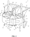
- a rotary regenerative air preheater is generally designated by the numeral 1.
- the preheater 1 includes a rotor assembly 2 rotatably mounted on a rotor post 3.
- the rotor assembly 2 is positioned in and rotates relative to a housing 4.
- the rotor assembly 2 is rotatable about an axis A of the rotor post 3 in the direction indicated by the arrow R.
- the rotor assembly 2 includes partitions 5 (e.g., diaphragms) extending radially from the rotor post 3 to an outer periphery of the rotor assembly 2. Adjacent pairs of the partitions 5 define respective compartments 6 for receiving a heat transfer sheet assembly 7.
- Each of the heat transfer sheet assemblies 7 include a plurality of heat transfer sheets 8 and/or 9 (see, for example, Figure 2 ) stacked against one another.
- the housing 4 includes a flue gas inlet duct 10 and a flue gas outlet duct 11 for the flow of heated flue gases through the preheater 1.
- the housing 4 further includes an air inlet duct 12 and an air outlet duct 13 for the flow of combustion air through the preheater 1.
- the preheater 1 includes an upper sector plate 14 extending across the housing 4 adjacent to an upper face of the rotor assembly 2.
- the preheater 1 includes a lower sector plate 15 extending across the housing 4 adjacent to lower face of the rotor assembly 2.
- the upper sector plate 14 extends between and is joined to the flue gas inlet duct 10 and the air outlet duct 13.
- the lower sector plate 15 extends between and is joined to the flue gas outlet duct 11 and the air inlet duct 12.
- the upper and lower sector plates, 14 and 15 respectively, are joined to one another by a circumferential plate 16.
- the upper sector plate 14 and the lower sector plate 15 divide the preheater 1 into an air sector 17 and a gas sector 18.
- the arrows marked 'A' indicate the direction of a flue gas stream 19 through the gas sector 18 of the rotor assembly 2.
- the arrows marked 'B' indicate the direction of a combustion air stream 20 through the air sector 17 of the rotor assembly 2.
- the flue gas stream 19 enters through the flue gas inlet duct 10 and transfers heat to the assemblies 7 mounted in the compartments 6.
- the heated assemblies 7 are rotated into the air sector 17 of the preheater 1. Heat stored in the assemblies 7 is then transferred to the combustion air stream 20 entering through the air inlet duct 12.
- the heat absorbed from the hot flue gas stream 19 entering into the preheater 1 is utilized for heating the assemblies 7, which in turn heats the combustion air stream 20.
- the heat transfer assembly 7 comprises a laminate of a multiplicity of heat transfer sheet elements 8 and 9 closely packed one after another under pressure and with sheets 8, 9 having distinct profiles.
- First sheet element 8, also illustrated in Figure 3 is of a first profile or configuration comprising parallel wide gauged first 21 and second 22 sheet spacing features called notches which in this embodiment are in lateral cross-section of lobular form with oppositely extending lobes preferentially connected by a flat sheet material section operatively effective accurately to space apart adjacent elements.
- the lobular sheet spacing features 21, 22 extend parallel to the direction of intended gaseous flow from one end of the sheet to the other.
- Second sheet element 9, also illustrated in Figure 4 is of a second profile or configuration comprising parallel wide gauged third 23 and fourth 24 sheeting spacing features which in this embodiment are flats generally in the nominal plane of element 9 which seat respectively against the features 21 and 22 of elements 8 (i.e. one sheet 8 under element 9 as shown in Figure 2 and another element 8 over, not illustrated).
- the features of element 9 are also illustrated on Figure 6 and the same features together with those of element 8 are illustrated on the cross-section of Figure 5 . From this cross-section it can be seen that the wide gauges of features 21, 22 and of features 23, 24 are equivalent so that features 21, 23 and 22, 24 respectively cooperate by seating one against the other to define an elongate close-sided gaseous flow channel 25 extending from one end of the assembly to the other.
- element 8 is provided with lobes 21, 22 and sheet 9 with flats 23, 24, it remains conceivable that in another embodiment of the invention element 8 is provided with flats and element 9 with lobes. In yet another embodiment element 8 could be provided with a mixture of lobes and flats whilst element 9 has a corresponding and associated plurality of flats and lobes. In a further embodiment it could be that both elements 8 and 9 are provided with lobes or other crimped or stamped structures that facilitate the spacing apart of the sheets so as to define a plurality of close-sided gaseous flow channels 25 within the assembly 7.
- Heat transfer sheet element 9 additionally in this and other embodiments of the invention comprises a fifth intermediate elongate sheet spacing feature 26 typically parallel and equidistant from its features 23 and 24.
- Element 9 further comprises a plurality of heat transfer undulations 27,28 of lesser amplitude than feature 26 extending laterally of the element 9 obliquely to the gaseous flow direction.
- Undulations 27 extend typically obliquely between the third 23 and fifth 26 sheet spacing features and similarly undulations 28 extend between the fifth 26 and fourth 24 sheet spacing features.
- element 8 further comprises a plurality of heat transfer undulations 29 of lesser amplitude than the sheet spacing features 21, 22 extending laterally of element 8 therebetween and obliquely to the direction of gaseous flow and as illustrated in this first embodiment also obliquely of the undulations 27, 28 of the second sheet 9.
- the undulations 27, 28, and 29 are of similar cross-section and undulations 27, 28 are oblique to undulations 29.
- the intermediate sheet spacing feature 26 of element 9 is in contact with the undulations 29 of element 8 and provides additional structural rigidity to the gas channel 25.
- sheet spacing feature 26 is of similar shape to the features 21, 22 albeit with lower amplitude and suitably extends the length or substantially the length of the element 8. In some embodiments, sheet spacing feature extends at least half of the length of element 8.
- sub-channels 30, 31 within the channel 25 can be found sub-channels 30, 31 with the intermediate sheet spacing feature 26 further defining a shared longitudinal side wall therebetween.
- sub-channel 30 is defined between immediately adjacent pairs of sheet spacing features 21, 23 providing a closed side-wall and adjacent intermediate sheet spacing feature 26 contacting opposing peaks of undulations 29 providing a side-wall perforated by troughs of the undulations 29.
- sub-channel 31 is defined between immediately adjacent pairs of sheet spacing features 22, 24 providing a closed side-wall and the adjacent intermediate sheet spacing feature 26 contacting opposing peaks of undulations 29 providing a side-wall perforated by troughs of the undulations 29.
- the side-wall provided by the cooperation of feature 26 and undulations 29 is perforated to permit some transverse gaseous flow under the intermediate sheet spacing feature 26 whilst at the same time disturbing bulk skew along undulations 29.
- the intermediate sheet spacing feature 26 may provide an increased surface area for heat transfer as compared to other designs. This is believed in combination to be contributory to improved thermal performance of the heat transfer assembly.
- intermediate sheet spacing feature 26 in mechanical contact with undulations 29 inhibits drumming and/or vibration of the elements 8 and 9 between the respective spacing features 21, 22 and 23, 24. This is believed to help reduce the incidence of mechanical and fatigue damage.
- the elongate intermediate sheet spacing feature 26 is replaced by an alternating notch configuration similar to the alternating notch disclosed in Applicant's US Patent Application No. 14/877,451 filed on 7th October 2015 .
- intermediate sheet spacing feature 26 provides increased structural rigidity to the gaseous flow channel 25 defined between cooperating features 21, 23 and 22, 24. Because this feature 26 provides a perforated side-wall to sub-channels 30, 31 it has been found surprisingly not to impact efficiency negatively in the manner anticipated above for an assembly having smaller gaseous flow channels. It is believed this is because turbulent flow of gas transverse of the gaseous flow channel is facilitated by gaseous flow through valleys of undulations 29 of element 8 traversing the feature 26.
- the gaseous flow channel 25 can also be considered to be defined between opposing repeats R1, R2 of the first profile of first sheet element 8 and of the second profile of second sheet element 9 respectively.
- the first repeat R1 of the first profile is defined between and including immediately adjacent first sheet spacing features 21 and second sheet spacing features 22 on sheet 8, i.e. including the corresponding undulations 29 extending therebetween.
- the second repeat R2 of said second profile is defined between and including immediately adjacent third sheet spacing feature 23 and the fourth sheet spacing features 24, i.e. encompassing also the corresponding fifth intermediate sheet spacing feature 26 and undulations 27, 28 disposed therebetween.
- the repeats R1 and R2 are each contiguous on the respective sheet elements 8 and 9.
- the second sheet spacing feature 22 of a one first repeat R1 is equivalent to first sheet spacing feature 21 of the next immediately adjacent repeat R1.
- the fourth sheet spacing feature 24 of a one second repeat R2 is equivalent to third sheet spacing feature 23 of the next immediately adjacent repeat R2. It will be appreciated that rather than being contiguous the repeats R1 and R2 could be spaced apart on their respective sheet elements 8, 9.
- the repeats R1 and R2 could be pattern repeats respectively immediately adjacent the next repeats R1 and R2.
- the second sheet spacing feature 22 of a one first repeat R1 is alongside and contacting first sheet spacing feature 21 of the next immediately adjacent repeat R1 and the fourth sheet spacing feature 24 of a one second repeat R2 is alongside and contacting third sheet spacing feature 23 of the next immediately adjacent repeat R2.
- heat transfer sheet elements are manufactured by cutting a sheet steel roll to a desired size and then passing cut sheet sections through crimping rollers that are profiled to impart the desired profiles to the crimped sheets. These crimped sheets are subsequently packed in a basket to create a heat transfer assembly having the desired flow, thermal and profiles configuration characteristics desired.
- manufacturing tolerances for heat transfer elements is ⁇ 0.1778 mm (7 thousandth of an inch). Because the sheet element 8 and 9 are of different profiles these are crimped by respective matched pairs of rollers in an embodiment. In assembling one sheet to another manufacturing tolerances are cumulative and dimensional fit is subject to a tolerance of ⁇ 0.3556 mm (14 thousandth of an inch) in a two-sheet assembly.
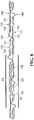
- FIG. 7 and 8 Another or second embodiment of the invention is manufactured using a single roll process and is illustrated in Figures 7 and 8 .
- the inventors have been able to achieve manufacturing tolerances of ⁇ 0.0762 mm (3 thousandth of an inch) which is consistent on adjacent sheets as they are cut from the same crimped stock, leading to improved consistency and thereby potentially improved quality during fabrication of a heat transfer assembly 100 resulting therefrom.
- the heat transfer assembly 100 comprises a laminate of a multiplicity of heat transfer sheet elements 101 and 102 closely packed one against another under pressure and aligned along their respective leading edges 103, 104.
- the sheet elements 101 and 102 are cut from the same crimped sheet stock and have the same third profile, repeating transversely across the elements 101, 102, which as clearly shown on the front face of element 101 illustrated comprises a flat first sheet spacing feature 105, a lobular second sheet spacing feature 106, a lobular third sheet spacing feature 107, wide gauge undulated planar heat transfer portion 108, and narrow gauge undulated planar heat transfer portions 109, 110.
- the sheet spacing features 106, 107 are in lateral cross-section of lobular form with oppositely extending lobes preferentially connected by a flat sheet material section operatively effective accurately to space apart adjacent elements.
- the sheet spacing features 105 are flats generally in the nominal plane of the respective element 101, 102.
- the flat sheet spacing features 105 and the lobular sheet spacing features 106,107 extend longitudinally parallel to the direction of intended gaseous flow from one end of their respective sheet to the other.
- This third profile of the second embodiment comprises a first repeat R3 defined between and including one first sheet spacing feature 105 and the immediately adjacent second sheet spacing feature 106 on sheet 101, i.e. including the corresponding wide gauge undulated portion 108 extending therebetween.
- the third profile also comprises a second repeat R4 defined between and including the aforementioned second sheet spacing feature 106 and the immediately adjacent next first sheet spacing feature 105 disposed transversely from the aforementioned one first sheet spacing feature 105, i.e. encompassing also the corresponding third intermediate sheet spacing feature 107 and the narrow gauge undulated portions 109, 110 disposed therebetween.
- repeats R3, R4 in this second embodiment correspond in an operative sense respectively to repeats R1, R2 of the first embodiment as illustrated in Figures 2 to 6 .
- the heat transfer assembly 100 is fabricated with repeats R3 on element 101 being paired with repeats R4 on element 102 and vice versa. Consequently, the intended spacing of element 101 and 102 is effected by the flat sheet spacing features 105 on one element 101, 102 seating against a corresponding lobular sheet spacing feature 106 on the other element 101, 102 and vice versa, i.e.
- the planar orientation of elements 101,102 is the same so that the front face of one element opposes and in part contacts the back face of an immediately adjacent element and vice versa.
- Matched pairs of repeats R3 and R4 with one being disposed on one of element 101, 102 and the other disposed on the other element 101, 102, provide a corresponding plurality of wide gauged closed-sided gaseous flow channels 125 each being bisected by a perforated mid-wall comprising the associated third sheet spacing feature 107 to provide a corresponding pair of sub-channels 130, 131. It will be understood that the channels 125, 130, 131 are functionally as described for the channels 25, 30, 31 of the first embodiment of Figure 5 .
- the spacing between adjacent elements 101, 102 is maintained and overall structural rigidity may be improved by the elongate intermediate sheet spacing features 107 being in contact with peaks of the undulations 108 of immediately adjacent elements 101, 102.
- the amplitude of the intermediate sheet spacing features 107 is desirably equivalent to the amplitude of the undulations of the lobular sheet spacing features 106 less the maximum amplitude of undulations of which undulated portion 108 is comprised thereby ensuring point contact therealong.
- the wide gauge undulated portions 108 each comprise a plurality of elongate parallel elongate lobular heat transfer undulations 111 extending obliquely to the direction of intended gaseous flow in a first right hand direction, and uninterrupted between the heat spacing features 105, 106.
- the narrow gauge undulated portions 109, 110 respectively comprise a plurality of bisected lobular heat transfer undulations 112, 113 extending parallel to one another and obliquely to the direction of intended gaseous flow in a second left hand direction, and between the heat spacing features 106, 105 but bisected by the intermediate heat spacing feature 107.
- the undulations 112, 113 are of equal or near equal length.
- the axes respectively of corresponding right hand elongate undulations 111 and left hand bisected undulations 112, 113 intersect. Typically, these axes intersect at an angle of between 45 and 90 degrees.
- the axes of elongate undulations 111 intersect the longitudinal axes of the sheet spacing features 105, 106 at an angle of between 15 and 45 degrees.
- the axes of bisected undulations 112, 113 intersect the longitudinal axes of the sheet spacing features 105, 106, 107 at an angle of between 15 and 45 degrees.
- the elongate undulations 111 are each formed with intersecting flat side portions 114, 115 respectively meeting at the corresponding peak thereof.
- bisected undulations 112 are formed with intersecting flat side portions 116, 117 and bisected undulations 113 are formed with flat side portions 118, 119.
- the lateral cross-sectional profiles of undulations 111, 112 and 113 are identical having amplitudes in the order of half the spacing provided by the interaction of sheet spacing features 105, 106 minus the width of the gaseous flow channels 125.
- heat transfer assemblies in accordance with this second embodiment would in practice reach a target up to 8 percent improvement in performance over different assemblies operating with the same thermal mass, gas input temperatures and pressure drop characteristics.
- a larger roll typically at least demonstrably larger and have in one embodiment adopted a nominal 560 mm (22 inch) crimping.
- the inventors have found that it is beneficial to ensure additional peripheral stability by providing additional support to the first and last elements 101, 102 in the stack. In particular supporting the peripheral undulated portions 108, 109, 110, i.e. those that do not oppose another undulated portion of another element 101, 102. This could be accomplished using support bars or other like formation attached to the baskets within which the elements 101,102 are stacked.
- a preferred construction is to sandwich the elements stack between two similar support plates or sheets with each having support features extending outwardly from the nominal planes of the respective plates which contact variously undulations 111, 112, 113 typically at contact points spaced apart by about 57 to 76 mm (2.25 to 3 inches), preferably every 69 mm (2.7 inches) appears effective in this regard.
Landscapes
- Engineering & Computer Science (AREA)
- Physics & Mathematics (AREA)
- Thermal Sciences (AREA)
- Mechanical Engineering (AREA)
- General Engineering & Computer Science (AREA)
- Heat-Exchange Devices With Radiators And Conduit Assemblies (AREA)
- Air Supply (AREA)
Claims (14)
- Wärmeübertragungsfolienanordnung für einen regenerativen Rotationswärmetauscher, umfassend: ein erstes Folienelement (8), das ein erstes Profil aufweist, das eine Vielzahl von parallelen und länglichen ersten und zweiten Folienabstandsmerkmalen (21, 22) umfasst, die sich in Längsrichtung in einer Gasströmungsrichtung erstrecken, wobei eine erste Wiederholung des ersten Profils zwischen unmittelbar angrenzenden ersten und zweiten Folienabstandsmerkmalen (21, 22) definiert ist und diese einschließt; undein zweites Folienelement (9) mit einer äquivalenten Länge mit einem zweiten Profil, das eine komplementäre Vielzahl von breit bemessenen, parallelen und länglichen dritten und vierten Folienabstandsmerkmalen (23, 24) umfasst, wobei eine zweite Wiederholung des zweiten Profils zwischen unmittelbar angrenzenden dritten und vierten Folienabstandsmerkmalen (23, 24) definiert ist und diese einschließt,wobei das erste Folienelement (8) gegen das zweite Folienelement (9) gepackt ist, wobei die ersten (21) und die dritten (23) Folienabstandsmerkmale der jeweiligen übereinstimmenden Paare von Elementen der ersten (8) und der zweiten Folie (9) und die Vielzahl von Abständen der zweiten (22) und vierten (24) Folie der jeweiligen übereinstimmenden Paare aneinander anliegen, um für jedes der übereinstimmenden Paare einen allgemein engseitigen länglichen Kanal für die Gasströmung durch diesen hindurch zu definieren,wobei das erste Folienelement (8) nockenförmige Wärmeübertragungswellungen (29) aufweist, die sich seitlich und ununterbrochen zwischen jedem der ersten (21) und zweiten (22) Abstandsmerkmale erstrecken,wobei das zweite Folienelement (9) ferner ein jeweiliges längliches fünftes Folienabstandsmerkmal (26) umfasst, das sich in Längsrichtung entlang mindestens einer halben Länge des zweiten Folienelements zwischen dem dritten (23) und vierten (24) Folienabstandsmerkmal jedes der übereinstimmenden Paare erstreckt, wobei jedes fünfte Folienabstandsmerkmal (26) einen Nocken umfasst, wobei der Nocken des fünften Folienabstandsmerkmals (26) eine Amplitude kleiner oder gleich einem Abstand aufweist, der durch die anliegenden ersten (21) und dritten (23) Folienabstandsmerkmale und die anliegenden zweiten (22) und vierten (24) Folienabstandsmerkmale bereitgestellt wird, dadurch gekennzeichnet, dass der Nocken des fünften Folienabstandsmerkmals (26) mindestens einige der nockenförmigen Wärmeübertragungswellungen (29) zwischen den ersten (21) und zweiten (22) Folienabstandsmerkmalen eines jeweiligen übereinstimmenden Paares berührt.
- Wärmeübertragungsfolienanordnung nach Anspruch 1, dadurch gekennzeichnet, dass das erste Folienabstandsmerkmal (21) einen Nocken umfasst, der sich von der Nominalebene des ersten Folienelements (8) weg erstreckt und das dritte Folienabstandsmerkmal (23) eine Abflachung in der Nominalebene des zweiten Folienelements (9) umfasst.
- Wärmeübertragungsfolienanordnung nach Anspruch 1 oder Anspruch 2, dadurch gekennzeichnet, dass das zweite Folienabstandsmerkmal (22) einen Nocken umfasst, der sich von der Nominalebene des ersten Folienelements (8) weg erstreckt und das vierte Folienmerkmal (24) eine Abflachung in der Nominalebene des zweiten Folienelements (9) umfasst.
- Wärmeübertragungsfolienanordnung nach einem der vorstehenden Ansprüche, dadurch gekennzeichnet, dass das fünfte Folienabstandsmerkmal (26) eine Kerbkonfiguration ist, die eine Kerbe umfasst, die sich entlang des zweiten Folienelements (9) erstreckt, und wobei sich der Nocken von der Nominalebene des zweiten Folienelements (9) weg in Richtung des ersten Folienelements (8) erstreckt und ein zweiter Nocken sich in der entgegengesetzten Richtung von dem ersten Folienelement (8) weg erstreckt, wobei die zwei Nocken durch einen flachen Folienabschnitt verbunden sind.
- Wärmeübertragungsfolienanordnung nach einem der Ansprüche 1 bis 3, dadurch gekennzeichnet, dass das fünfte Folienabstandsmerkmal (26) eine alternierende Kerbkonfiguration ist, die sich entlang des zweiten Folienelements (9) erstreckt und mindestens einen ersten länglichen Abschnitt umfasst, der einen Nocken oder eine Kerbe aufweist, der/die sich von der Mittelebene der zweiten Folie (9) weg in Richtung des ersten Folienelements (8), angrenzend an mindestens einen zweiten länglichen Abschnitt erstreckt, wobei gegenüberliegende Enden des ersten und zweiten länglichen Abschnitts miteinander verbunden sind.
- Wärmeübertragungsfolienanordnung nach Anspruch 5, dadurch gekennzeichnet, dass der zweite längliche Abschnitt einen Nocken umfasst, der sich von der Mittelebene des zweiten Folienelements (9) weg in Gegenrichtung des ersten länglichen Profilnockens erstreckt.
- Wärmeübertragungsfolienanordnung nach einem der vorstehenden Ansprüche, dadurch gekennzeichnet, dass das zweite Folienelement (9) ferner nockenförmige Wärmeübertragungswellungen (27, 28) umfasst, die sich seitlich und ununterbrochen zwischen dem dritten (23) und fünften (26) Folienabstandsmerkmal bzw. dem fünften (26) und vierten (24) Folienabstandsmerkmal erstrecken.
- Wärmeübertragungsfolienanordnung nach Anspruch 7, dadurch gekennzeichnet, dass die Wellungen (29) des ersten Folienelements (8) schräg zu den Wellungen (27, 28) des zweiten Folienelements verlaufen.
- Wärmeübertragungsfolienanordnung nach Anspruch 1, dadurch gekennzeichnet, dass das erste Folienelement (8, 101) und das zweite Folienelement (9, 102) ein Folienmaterial umfassen, das ein zusammengesetztes drittes Profil aufweist, das sowohl die erste Wiederholung des ersten Profils als auch die zweite Wiederholung des zweiten Profils umfasst, wobei die erste Wiederholung und die zweite Wiederholung seitlich über die Folie alternieren und wobei eines der ersten (104) und zweiten (105) Folienabstandsmerkmale eine derartige Wiederholung beendet, wodurch eines der dritten (106) und vierten (106) Folienabstandsmerkmale bereitgestellt wird, die seitlich eine unmittelbar angrenzende zweite Wiederholung beginnen, und wobei ein weiteres der dritten (106) und vierten (106) Folienabstandsmerkmale, die seitlich die unmittelbar angrenzende zweite Wiederholung beenden, ein weiteres der ersten (104) und zweiten (105) Folienabstandsmerkmale bereitstellen, die seitlich eine nächste unmittelbar angrenzende Wiederholung beginnen.
- Wärmeübertragungsfolienanordnung nach Anspruch 9, dadurch gekennzeichnet, dass die erste Wiederholung seitlich mit einer Abflachung in einer Nominalebene des Folienmaterials beginnt, das das erste Folienabstandsmerkmal (104) umfasst, und mit einem Nocken endet, der sich von der Nominalebene des Folienmaterials weg erstreckt, das das zweite Folienabstandsmerkmal (105) umfasst und ebenfalls das dritte Folienabstandsmerkmal (106) bereitstellt, das die unmittelbar angrenzende zweite Wiederholung beginnt, die mit einer Abflachung endet, die das vierte Folienabstandsmerkmal (106) der unmittelbar angrenzenden zweiten Wiederholung und das erste Folienabstandsmerkmal (104) der nächsten unmittelbar angrenzende ersten Wiederholung bereitstellt, und wobei die unmittelbar angrenzende zweite Wiederholung zwischen ihren dritten (106) und vierten (104) Folienabstandsmerkmalen das fünfte Folienabstandsmerkmal aufweist, wobei sich der Nocken des fünften Folienabstandsmerkmals von der Nominalebene des Folienmaterials weg erstreckt.
- Wärmeübertragungsfolienanordnung nach Anspruch 10, dadurch gekennzeichnet, dass das Folienmaterial eine Vorderseite und eine Rückseite aufweist, die für die Wärmeübertragung verfügbar sind, wobei die Vorderseite des ersten Folienelements der Rückseite des zweiten Folienelements gegenüberliegt und diese teilweise berührt.
- Wärmeübertragungsfolienanordnung nach Anspruch 9, dadurch gekennzeichnet, dass die erste Wiederholung des ersten Profils längliche, nockenförmige Wärmeübertragungswellungen (108) umfasst, die sich schräg und ununterbrochen zwischen den ersten (104) und zweiten (105) Folienabstandsmerkmalen erstrecken, die das erste Profil beginnen und beenden, und die zweite Wiederholung des zweiten Profils zweigeteilte nockenförmige Wärmeübertragungswellungen umfasst, die sich schräg zwischen den zweiten (105) und dritten (106) Folienabstandsmerkmalen erstrecken, die das zweite Profil beginnen und enden, das durch das fünfte Folienabstandsmerkmal zweigeteilt ist.
- Wärmeübertragungsfolienanordnung nach Anspruch 12, dadurch gekennzeichnet, dass die länglichen Wellungen (105) sich in einer ersten Richtung erstrecken und die zweigeteilten Wellungen sich in einer zweiten Richtung erstrecken, die sich von der ersten Richtung unterscheidet.
- Wärmeübertragungsfolienanordnung nach einem der vorstehenden Ansprüche, umfassend eine Vielfalt von ersten Folienelementen (8, 101) und zweiten (9, 102) Folienelementen, die in einem Korb gestapelt und zwischen zwei Stützfolien schichtweise angeordnet sind, wobei sich die Wärmeübertragungswellungen von den Folienelementen nach außen, unmittelbar angrenzend an eine jeweilige Stützfolie, erstrecken, wobei sie die jeweilige Stützfolie an Stützpunkten berühren, die seitlich in Abständen von etwa 57 bis 76 mm (2,25 bis 3 Zoll) zueinander angeordnet sind.
Priority Applications (1)
| Application Number | Priority Date | Filing Date | Title |
|---|---|---|---|
| PL17719115T PL3563109T3 (pl) | 2016-12-29 | 2017-04-10 | Zespół arkusza blachy z funkcją wymiany ciepła oraz rozstawu pośredniego |
Applications Claiming Priority (2)
| Application Number | Priority Date | Filing Date | Title |
|---|---|---|---|
| PCT/US2016/069186 WO2018125134A1 (en) | 2016-12-29 | 2016-12-29 | A heat transfer sheet assembly with an intermediate spacing feature |
| PCT/US2017/026840 WO2018125270A1 (en) | 2016-12-29 | 2017-04-10 | A heat transfer sheet assembly with an intermediate spacing feature |
Publications (2)
| Publication Number | Publication Date |
|---|---|
| EP3563109A1 EP3563109A1 (de) | 2019-11-06 |
| EP3563109B1 true EP3563109B1 (de) | 2022-03-30 |
Family
ID=57851357
Family Applications (1)
| Application Number | Title | Priority Date | Filing Date |
|---|---|---|---|
| EP17719115.2A Active EP3563109B1 (de) | 2016-12-29 | 2017-04-10 | Wärmeübertragungsfolienanordnung mit zwischenräumen |
Country Status (15)
| Country | Link |
|---|---|
| US (1) | US11236949B2 (de) |
| EP (1) | EP3563109B1 (de) |
| JP (1) | JP7036516B2 (de) |
| KR (1) | KR102357234B1 (de) |
| CN (1) | CN110462325B (de) |
| AU (1) | AU2017384971B2 (de) |
| ES (1) | ES2915556T3 (de) |
| MX (1) | MX2019007790A (de) |
| MY (1) | MY198123A (de) |
| PH (1) | PH12019501476B1 (de) |
| PL (1) | PL3563109T3 (de) |
| SA (1) | SA519402136B1 (de) |
| TW (1) | TW201825851A (de) |
| WO (2) | WO2018125134A1 (de) |
| ZA (1) | ZA201904665B (de) |
Families Citing this family (3)
| Publication number | Priority date | Publication date | Assignee | Title |
|---|---|---|---|---|
| CN114001545A (zh) * | 2021-09-13 | 2022-02-01 | 南京宜热纵联节能科技有限公司 | 一种热回收式供热系统 |
| KR102564035B1 (ko) * | 2021-11-01 | 2023-08-04 | 조선대학교산학협력단 | 회전 재생식 열교환기의 열교환 소자 |
| CN117650312B (zh) * | 2024-01-30 | 2024-04-26 | 深圳市科瑞隆科技有限公司 | 一种耐高温的聚合物锂电池组 |
Family Cites Families (15)
| Publication number | Priority date | Publication date | Assignee | Title |
|---|---|---|---|---|
| SE127755C1 (sv) | 1945-05-28 | 1950-03-28 | Ljungstroms Angturbin Ab | Elementsats för värmeväxlare |
| US4396058A (en) | 1981-11-23 | 1983-08-02 | The Air Preheater Company | Heat transfer element assembly |
| US4744410A (en) | 1987-02-24 | 1988-05-17 | The Air Preheater Company, Inc. | Heat transfer element assembly |
| US5318102A (en) * | 1993-10-08 | 1994-06-07 | Wahlco Power Products, Inc. | Heat transfer plate packs and baskets, and their utilization in heat recovery devices |
| US5836379A (en) | 1996-11-22 | 1998-11-17 | Abb Air Preheater, Inc. | Air preheater heat transfer surface |
| US5979050A (en) * | 1997-06-13 | 1999-11-09 | Abb Air Preheater, Inc. | Air preheater heat transfer elements and method of manufacture |
| US5899261A (en) * | 1997-09-15 | 1999-05-04 | Abb Air Preheater, Inc. | Air preheater heat transfer surface |
| US6019160A (en) * | 1998-12-16 | 2000-02-01 | Abb Air Preheater, Inc. | Heat transfer element assembly |
| US6179276B1 (en) * | 1999-02-17 | 2001-01-30 | Abb Air Preheater, Inc. | Heat and mass transfer element assembly |
| US6516871B1 (en) | 1999-08-18 | 2003-02-11 | Alstom (Switzerland) Ltd. | Heat transfer element assembly |
| US20030178173A1 (en) * | 2002-03-22 | 2003-09-25 | Alstom (Switzerland) Ltd. | Heat transfer surface for air preheater |
| US9557119B2 (en) * | 2009-05-08 | 2017-01-31 | Arvos Inc. | Heat transfer sheet for rotary regenerative heat exchanger |
| US8622115B2 (en) * | 2009-08-19 | 2014-01-07 | Alstom Technology Ltd | Heat transfer element for a rotary regenerative heat exchanger |
| US9644899B2 (en) * | 2011-06-01 | 2017-05-09 | Arvos, Inc. | Heating element undulation patterns |
| US9200853B2 (en) | 2012-08-23 | 2015-12-01 | Arvos Technology Limited | Heat transfer assembly for rotary regenerative preheater |
-
2016
- 2016-12-29 WO PCT/US2016/069186 patent/WO2018125134A1/en not_active Ceased
-
2017
- 2017-04-10 WO PCT/US2017/026840 patent/WO2018125270A1/en not_active Ceased
- 2017-04-10 PH PH1/2019/501476A patent/PH12019501476B1/en unknown
- 2017-04-10 PL PL17719115T patent/PL3563109T3/pl unknown
- 2017-04-10 CN CN201780081214.8A patent/CN110462325B/zh active Active
- 2017-04-10 KR KR1020197020969A patent/KR102357234B1/ko active Active
- 2017-04-10 MY MYPI2019003654A patent/MY198123A/en unknown
- 2017-04-10 AU AU2017384971A patent/AU2017384971B2/en active Active
- 2017-04-10 EP EP17719115.2A patent/EP3563109B1/de active Active
- 2017-04-10 JP JP2019535375A patent/JP7036516B2/ja active Active
- 2017-04-10 US US16/473,444 patent/US11236949B2/en active Active
- 2017-04-10 ES ES17719115T patent/ES2915556T3/es active Active
- 2017-04-10 MX MX2019007790A patent/MX2019007790A/es unknown
- 2017-11-16 TW TW106139752A patent/TW201825851A/zh unknown
-
2019
- 2019-06-27 SA SA519402136A patent/SA519402136B1/ar unknown
- 2019-07-16 ZA ZA2019/04665A patent/ZA201904665B/en unknown
Also Published As
| Publication number | Publication date |
|---|---|
| CN110462325B (zh) | 2021-04-02 |
| PL3563109T3 (pl) | 2022-06-27 |
| ES2915556T3 (es) | 2022-06-23 |
| MX2019007790A (es) | 2019-10-30 |
| PH12019501476A1 (en) | 2020-03-09 |
| KR20190103219A (ko) | 2019-09-04 |
| CN110462325A (zh) | 2019-11-15 |
| TW201825851A (zh) | 2018-07-16 |
| SA519402136B1 (ar) | 2022-06-16 |
| US20200149824A1 (en) | 2020-05-14 |
| AU2017384971A1 (en) | 2019-08-08 |
| US11236949B2 (en) | 2022-02-01 |
| MY198123A (en) | 2023-08-04 |
| ZA201904665B (en) | 2021-02-24 |
| PH12019501476B1 (en) | 2022-08-12 |
| JP7036516B2 (ja) | 2022-03-15 |
| WO2018125270A1 (en) | 2018-07-05 |
| AU2017384971B2 (en) | 2023-02-02 |
| KR102357234B1 (ko) | 2022-01-28 |
| JP2020503488A (ja) | 2020-01-30 |
| EP3563109A1 (de) | 2019-11-06 |
| WO2018125134A1 (en) | 2018-07-05 |
Similar Documents
| Publication | Publication Date | Title |
|---|---|---|
| EP2715266B1 (de) | Wärmeübertragungsblech | |
| KR100445821B1 (ko) | 열 및 물질 전달 요소 조립체 | |
| CA2616201C (en) | Heat exchange surface | |
| TWI583896B (zh) | 用於旋轉式再生預熱器之熱傳導總成 | |
| KR20010090870A (ko) | 열전달 부재 조립체 | |
| AU2017384971B2 (en) | A heat transfer sheet assembly with an intermediate spacing feature | |
| KR102641497B1 (ko) | 열전달 시트, 열전달 조립체, 열교환기 시트들의 적층체, 및 열전달 시트들의 적층체를 위한 이격 시트 |
Legal Events
| Date | Code | Title | Description |
|---|---|---|---|
| STAA | Information on the status of an ep patent application or granted ep patent |
Free format text: STATUS: UNKNOWN |
|
| STAA | Information on the status of an ep patent application or granted ep patent |
Free format text: STATUS: THE INTERNATIONAL PUBLICATION HAS BEEN MADE |
|
| PUAI | Public reference made under article 153(3) epc to a published international application that has entered the european phase |
Free format text: ORIGINAL CODE: 0009012 |
|
| STAA | Information on the status of an ep patent application or granted ep patent |
Free format text: STATUS: REQUEST FOR EXAMINATION WAS MADE |
|
| 17P | Request for examination filed |
Effective date: 20190724 |
|
| AK | Designated contracting states |
Kind code of ref document: A1 Designated state(s): AL AT BE BG CH CY CZ DE DK EE ES FI FR GB GR HR HU IE IS IT LI LT LU LV MC MK MT NL NO PL PT RO RS SE SI SK SM TR |
|
| AX | Request for extension of the european patent |
Extension state: BA ME |
|
| DAV | Request for validation of the european patent (deleted) | ||
| DAX | Request for extension of the european patent (deleted) | ||
| GRAP | Despatch of communication of intention to grant a patent |
Free format text: ORIGINAL CODE: EPIDOSNIGR1 |
|
| STAA | Information on the status of an ep patent application or granted ep patent |
Free format text: STATUS: GRANT OF PATENT IS INTENDED |
|
| INTG | Intention to grant announced |
Effective date: 20210923 |
|
| GRAS | Grant fee paid |
Free format text: ORIGINAL CODE: EPIDOSNIGR3 |
|
| GRAA | (expected) grant |
Free format text: ORIGINAL CODE: 0009210 |
|
| STAA | Information on the status of an ep patent application or granted ep patent |
Free format text: STATUS: THE PATENT HAS BEEN GRANTED |
|
| AK | Designated contracting states |
Kind code of ref document: B1 Designated state(s): AL AT BE BG CH CY CZ DE DK EE ES FI FR GB GR HR HU IE IS IT LI LT LU LV MC MK MT NL NO PL PT RO RS SE SI SK SM TR |
|
| REG | Reference to a national code |
Ref country code: GB Ref legal event code: FG4D |
|
| REG | Reference to a national code |
Ref country code: CH Ref legal event code: EP |
|
| REG | Reference to a national code |
Ref country code: AT Ref legal event code: REF Ref document number: 1479558 Country of ref document: AT Kind code of ref document: T Effective date: 20220415 |
|
| REG | Reference to a national code |
Ref country code: DE Ref legal event code: R096 Ref document number: 602017055176 Country of ref document: DE |
|
| REG | Reference to a national code |
Ref country code: IE Ref legal event code: FG4D |
|
| REG | Reference to a national code |
Ref country code: ES Ref legal event code: FG2A Ref document number: 2915556 Country of ref document: ES Kind code of ref document: T3 Effective date: 20220623 |
|
| REG | Reference to a national code |
Ref country code: LT Ref legal event code: MG9D |
|
| PG25 | Lapsed in a contracting state [announced via postgrant information from national office to epo] |
Ref country code: SE Free format text: LAPSE BECAUSE OF FAILURE TO SUBMIT A TRANSLATION OF THE DESCRIPTION OR TO PAY THE FEE WITHIN THE PRESCRIBED TIME-LIMIT Effective date: 20220330 Ref country code: RS Free format text: LAPSE BECAUSE OF FAILURE TO SUBMIT A TRANSLATION OF THE DESCRIPTION OR TO PAY THE FEE WITHIN THE PRESCRIBED TIME-LIMIT Effective date: 20220330 Ref country code: NO Free format text: LAPSE BECAUSE OF FAILURE TO SUBMIT A TRANSLATION OF THE DESCRIPTION OR TO PAY THE FEE WITHIN THE PRESCRIBED TIME-LIMIT Effective date: 20220630 Ref country code: LT Free format text: LAPSE BECAUSE OF FAILURE TO SUBMIT A TRANSLATION OF THE DESCRIPTION OR TO PAY THE FEE WITHIN THE PRESCRIBED TIME-LIMIT Effective date: 20220330 Ref country code: HR Free format text: LAPSE BECAUSE OF FAILURE TO SUBMIT A TRANSLATION OF THE DESCRIPTION OR TO PAY THE FEE WITHIN THE PRESCRIBED TIME-LIMIT Effective date: 20220330 Ref country code: BG Free format text: LAPSE BECAUSE OF FAILURE TO SUBMIT A TRANSLATION OF THE DESCRIPTION OR TO PAY THE FEE WITHIN THE PRESCRIBED TIME-LIMIT Effective date: 20220630 |
|
| REG | Reference to a national code |
Ref country code: NL Ref legal event code: MP Effective date: 20220330 |
|
| REG | Reference to a national code |
Ref country code: AT Ref legal event code: MK05 Ref document number: 1479558 Country of ref document: AT Kind code of ref document: T Effective date: 20220330 |
|
| PG25 | Lapsed in a contracting state [announced via postgrant information from national office to epo] |
Ref country code: LV Free format text: LAPSE BECAUSE OF FAILURE TO SUBMIT A TRANSLATION OF THE DESCRIPTION OR TO PAY THE FEE WITHIN THE PRESCRIBED TIME-LIMIT Effective date: 20220330 Ref country code: GR Free format text: LAPSE BECAUSE OF FAILURE TO SUBMIT A TRANSLATION OF THE DESCRIPTION OR TO PAY THE FEE WITHIN THE PRESCRIBED TIME-LIMIT Effective date: 20220701 Ref country code: FI Free format text: LAPSE BECAUSE OF FAILURE TO SUBMIT A TRANSLATION OF THE DESCRIPTION OR TO PAY THE FEE WITHIN THE PRESCRIBED TIME-LIMIT Effective date: 20220330 |
|
| PG25 | Lapsed in a contracting state [announced via postgrant information from national office to epo] |
Ref country code: NL Free format text: LAPSE BECAUSE OF FAILURE TO SUBMIT A TRANSLATION OF THE DESCRIPTION OR TO PAY THE FEE WITHIN THE PRESCRIBED TIME-LIMIT Effective date: 20220330 |
|
| PG25 | Lapsed in a contracting state [announced via postgrant information from national office to epo] |
Ref country code: SM Free format text: LAPSE BECAUSE OF FAILURE TO SUBMIT A TRANSLATION OF THE DESCRIPTION OR TO PAY THE FEE WITHIN THE PRESCRIBED TIME-LIMIT Effective date: 20220330 Ref country code: SK Free format text: LAPSE BECAUSE OF FAILURE TO SUBMIT A TRANSLATION OF THE DESCRIPTION OR TO PAY THE FEE WITHIN THE PRESCRIBED TIME-LIMIT Effective date: 20220330 Ref country code: RO Free format text: LAPSE BECAUSE OF FAILURE TO SUBMIT A TRANSLATION OF THE DESCRIPTION OR TO PAY THE FEE WITHIN THE PRESCRIBED TIME-LIMIT Effective date: 20220330 Ref country code: PT Free format text: LAPSE BECAUSE OF FAILURE TO SUBMIT A TRANSLATION OF THE DESCRIPTION OR TO PAY THE FEE WITHIN THE PRESCRIBED TIME-LIMIT Effective date: 20220801 Ref country code: EE Free format text: LAPSE BECAUSE OF FAILURE TO SUBMIT A TRANSLATION OF THE DESCRIPTION OR TO PAY THE FEE WITHIN THE PRESCRIBED TIME-LIMIT Effective date: 20220330 Ref country code: AT Free format text: LAPSE BECAUSE OF FAILURE TO SUBMIT A TRANSLATION OF THE DESCRIPTION OR TO PAY THE FEE WITHIN THE PRESCRIBED TIME-LIMIT Effective date: 20220330 |
|
| PG25 | Lapsed in a contracting state [announced via postgrant information from national office to epo] |
Ref country code: IS Free format text: LAPSE BECAUSE OF FAILURE TO SUBMIT A TRANSLATION OF THE DESCRIPTION OR TO PAY THE FEE WITHIN THE PRESCRIBED TIME-LIMIT Effective date: 20220730 Ref country code: AL Free format text: LAPSE BECAUSE OF FAILURE TO SUBMIT A TRANSLATION OF THE DESCRIPTION OR TO PAY THE FEE WITHIN THE PRESCRIBED TIME-LIMIT Effective date: 20220330 |
|
| REG | Reference to a national code |
Ref country code: CH Ref legal event code: PL |
|
| REG | Reference to a national code |
Ref country code: DE Ref legal event code: R097 Ref document number: 602017055176 Country of ref document: DE |
|
| REG | Reference to a national code |
Ref country code: BE Ref legal event code: MM Effective date: 20220430 |
|
| PG25 | Lapsed in a contracting state [announced via postgrant information from national office to epo] |
Ref country code: MC Free format text: LAPSE BECAUSE OF FAILURE TO SUBMIT A TRANSLATION OF THE DESCRIPTION OR TO PAY THE FEE WITHIN THE PRESCRIBED TIME-LIMIT Effective date: 20220330 Ref country code: LU Free format text: LAPSE BECAUSE OF NON-PAYMENT OF DUE FEES Effective date: 20220410 Ref country code: LI Free format text: LAPSE BECAUSE OF NON-PAYMENT OF DUE FEES Effective date: 20220430 Ref country code: DK Free format text: LAPSE BECAUSE OF FAILURE TO SUBMIT A TRANSLATION OF THE DESCRIPTION OR TO PAY THE FEE WITHIN THE PRESCRIBED TIME-LIMIT Effective date: 20220330 Ref country code: CH Free format text: LAPSE BECAUSE OF NON-PAYMENT OF DUE FEES Effective date: 20220430 |
|
| PLBE | No opposition filed within time limit |
Free format text: ORIGINAL CODE: 0009261 |
|
| STAA | Information on the status of an ep patent application or granted ep patent |
Free format text: STATUS: NO OPPOSITION FILED WITHIN TIME LIMIT |
|
| PG25 | Lapsed in a contracting state [announced via postgrant information from national office to epo] |
Ref country code: BE Free format text: LAPSE BECAUSE OF NON-PAYMENT OF DUE FEES Effective date: 20220430 |
|
| GBPC | Gb: european patent ceased through non-payment of renewal fee |
Effective date: 20220630 |
|
| 26N | No opposition filed |
Effective date: 20230103 |
|
| PG25 | Lapsed in a contracting state [announced via postgrant information from national office to epo] |
Ref country code: IE Free format text: LAPSE BECAUSE OF NON-PAYMENT OF DUE FEES Effective date: 20220410 Ref country code: FR Free format text: LAPSE BECAUSE OF NON-PAYMENT OF DUE FEES Effective date: 20220530 |
|
| PG25 | Lapsed in a contracting state [announced via postgrant information from national office to epo] |
Ref country code: SI Free format text: LAPSE BECAUSE OF FAILURE TO SUBMIT A TRANSLATION OF THE DESCRIPTION OR TO PAY THE FEE WITHIN THE PRESCRIBED TIME-LIMIT Effective date: 20220330 Ref country code: GB Free format text: LAPSE BECAUSE OF NON-PAYMENT OF DUE FEES Effective date: 20220630 |
|
| PG25 | Lapsed in a contracting state [announced via postgrant information from national office to epo] |
Ref country code: IT Free format text: LAPSE BECAUSE OF FAILURE TO SUBMIT A TRANSLATION OF THE DESCRIPTION OR TO PAY THE FEE WITHIN THE PRESCRIBED TIME-LIMIT Effective date: 20220330 |
|
| PG25 | Lapsed in a contracting state [announced via postgrant information from national office to epo] |
Ref country code: HU Free format text: LAPSE BECAUSE OF FAILURE TO SUBMIT A TRANSLATION OF THE DESCRIPTION OR TO PAY THE FEE WITHIN THE PRESCRIBED TIME-LIMIT; INVALID AB INITIO Effective date: 20170410 |
|
| PG25 | Lapsed in a contracting state [announced via postgrant information from national office to epo] |
Ref country code: MK Free format text: LAPSE BECAUSE OF FAILURE TO SUBMIT A TRANSLATION OF THE DESCRIPTION OR TO PAY THE FEE WITHIN THE PRESCRIBED TIME-LIMIT Effective date: 20220330 Ref country code: CY Free format text: LAPSE BECAUSE OF FAILURE TO SUBMIT A TRANSLATION OF THE DESCRIPTION OR TO PAY THE FEE WITHIN THE PRESCRIBED TIME-LIMIT Effective date: 20220330 |
|
| PG25 | Lapsed in a contracting state [announced via postgrant information from national office to epo] |
Ref country code: TR Free format text: LAPSE BECAUSE OF FAILURE TO SUBMIT A TRANSLATION OF THE DESCRIPTION OR TO PAY THE FEE WITHIN THE PRESCRIBED TIME-LIMIT Effective date: 20220330 |
|
| PG25 | Lapsed in a contracting state [announced via postgrant information from national office to epo] |
Ref country code: MT Free format text: LAPSE BECAUSE OF FAILURE TO SUBMIT A TRANSLATION OF THE DESCRIPTION OR TO PAY THE FEE WITHIN THE PRESCRIBED TIME-LIMIT Effective date: 20220330 |
|
| PGFP | Annual fee paid to national office [announced via postgrant information from national office to epo] |
Ref country code: DE Payment date: 20250204 Year of fee payment: 9 |
|
| PGFP | Annual fee paid to national office [announced via postgrant information from national office to epo] |
Ref country code: ES Payment date: 20250502 Year of fee payment: 9 |
|
| PGFP | Annual fee paid to national office [announced via postgrant information from national office to epo] |
Ref country code: CZ Payment date: 20260327 Year of fee payment: 10 |
|
| PGFP | Annual fee paid to national office [announced via postgrant information from national office to epo] |
Ref country code: PL Payment date: 20260325 Year of fee payment: 10 |