EP3562140A2 - Two axis pan tilt camera system configured to maintain a level image when wall or ceiling mounted - Google Patents
Two axis pan tilt camera system configured to maintain a level image when wall or ceiling mounted Download PDFInfo
- Publication number
- EP3562140A2 EP3562140A2 EP19170575.5A EP19170575A EP3562140A2 EP 3562140 A2 EP3562140 A2 EP 3562140A2 EP 19170575 A EP19170575 A EP 19170575A EP 3562140 A2 EP3562140 A2 EP 3562140A2
- Authority
- EP
- European Patent Office
- Prior art keywords
- camera
- support body
- wall
- ceiling
- subsystem
- Prior art date
- Legal status (The legal status is an assumption and is not a legal conclusion. Google has not performed a legal analysis and makes no representation as to the accuracy of the status listed.)
- Granted
Links
- 230000033001 locomotion Effects 0.000 claims abstract description 47
- 230000007246 mechanism Effects 0.000 claims description 11
- 230000007704 transition Effects 0.000 claims 1
- 230000008859 change Effects 0.000 description 17
- 238000010586 diagram Methods 0.000 description 12
- 210000005252 bulbus oculi Anatomy 0.000 description 6
- 238000009434 installation Methods 0.000 description 5
- 230000013011 mating Effects 0.000 description 5
- 238000000034 method Methods 0.000 description 5
- 230000005484 gravity Effects 0.000 description 4
- 238000012986 modification Methods 0.000 description 3
- 230000004048 modification Effects 0.000 description 3
- 230000005540 biological transmission Effects 0.000 description 2
- 230000006870 function Effects 0.000 description 2
- 238000004091 panning Methods 0.000 description 2
- 208000031872 Body Remains Diseases 0.000 description 1
- 239000003086 colorant Substances 0.000 description 1
- 238000010276 construction Methods 0.000 description 1
- 230000009977 dual effect Effects 0.000 description 1
- 230000000694 effects Effects 0.000 description 1
- 210000003128 head Anatomy 0.000 description 1
- 239000000463 material Substances 0.000 description 1
- 230000008569 process Effects 0.000 description 1
- 238000006467 substitution reaction Methods 0.000 description 1
Images


Classifications
-
- G—PHYSICS
- G08—SIGNALLING
- G08B—SIGNALLING OR CALLING SYSTEMS; ORDER TELEGRAPHS; ALARM SYSTEMS
- G08B13/00—Burglar, theft or intruder alarms
- G08B13/18—Actuation by interference with heat, light, or radiation of shorter wavelength; Actuation by intruding sources of heat, light, or radiation of shorter wavelength
- G08B13/189—Actuation by interference with heat, light, or radiation of shorter wavelength; Actuation by intruding sources of heat, light, or radiation of shorter wavelength using passive radiation detection systems
- G08B13/194—Actuation by interference with heat, light, or radiation of shorter wavelength; Actuation by intruding sources of heat, light, or radiation of shorter wavelength using passive radiation detection systems using image scanning and comparing systems
- G08B13/196—Actuation by interference with heat, light, or radiation of shorter wavelength; Actuation by intruding sources of heat, light, or radiation of shorter wavelength using passive radiation detection systems using image scanning and comparing systems using television cameras
- G08B13/19617—Surveillance camera constructional details
- G08B13/19632—Camera support structures, e.g. attachment means, poles
-
- H—ELECTRICITY
- H04—ELECTRIC COMMUNICATION TECHNIQUE
- H04N—PICTORIAL COMMUNICATION, e.g. TELEVISION
- H04N23/00—Cameras or camera modules comprising electronic image sensors; Control thereof
- H04N23/60—Control of cameras or camera modules
- H04N23/695—Control of camera direction for changing a field of view, e.g. pan, tilt or based on tracking of objects
-
- F—MECHANICAL ENGINEERING; LIGHTING; HEATING; WEAPONS; BLASTING
- F16—ENGINEERING ELEMENTS AND UNITS; GENERAL MEASURES FOR PRODUCING AND MAINTAINING EFFECTIVE FUNCTIONING OF MACHINES OR INSTALLATIONS; THERMAL INSULATION IN GENERAL
- F16M—FRAMES, CASINGS OR BEDS OF ENGINES, MACHINES OR APPARATUS, NOT SPECIFIC TO ENGINES, MACHINES OR APPARATUS PROVIDED FOR ELSEWHERE; STANDS; SUPPORTS
- F16M11/00—Stands or trestles as supports for apparatus or articles placed thereon Stands for scientific apparatus such as gravitational force meters
- F16M11/02—Heads
- F16M11/04—Means for attachment of apparatus; Means allowing adjustment of the apparatus relatively to the stand
- F16M11/06—Means for attachment of apparatus; Means allowing adjustment of the apparatus relatively to the stand allowing pivoting
- F16M11/12—Means for attachment of apparatus; Means allowing adjustment of the apparatus relatively to the stand allowing pivoting in more than one direction
- F16M11/121—Means for attachment of apparatus; Means allowing adjustment of the apparatus relatively to the stand allowing pivoting in more than one direction constituted of several dependent joints
- F16M11/123—Means for attachment of apparatus; Means allowing adjustment of the apparatus relatively to the stand allowing pivoting in more than one direction constituted of several dependent joints the axis of rotation intersecting in a single point, e.g. by using gimbals
-
- F—MECHANICAL ENGINEERING; LIGHTING; HEATING; WEAPONS; BLASTING
- F16—ENGINEERING ELEMENTS AND UNITS; GENERAL MEASURES FOR PRODUCING AND MAINTAINING EFFECTIVE FUNCTIONING OF MACHINES OR INSTALLATIONS; THERMAL INSULATION IN GENERAL
- F16M—FRAMES, CASINGS OR BEDS OF ENGINES, MACHINES OR APPARATUS, NOT SPECIFIC TO ENGINES, MACHINES OR APPARATUS PROVIDED FOR ELSEWHERE; STANDS; SUPPORTS
- F16M11/00—Stands or trestles as supports for apparatus or articles placed thereon Stands for scientific apparatus such as gravitational force meters
- F16M11/02—Heads
- F16M11/18—Heads with mechanism for moving the apparatus relatively to the stand
-
- F—MECHANICAL ENGINEERING; LIGHTING; HEATING; WEAPONS; BLASTING
- F16—ENGINEERING ELEMENTS AND UNITS; GENERAL MEASURES FOR PRODUCING AND MAINTAINING EFFECTIVE FUNCTIONING OF MACHINES OR INSTALLATIONS; THERMAL INSULATION IN GENERAL
- F16M—FRAMES, CASINGS OR BEDS OF ENGINES, MACHINES OR APPARATUS, NOT SPECIFIC TO ENGINES, MACHINES OR APPARATUS PROVIDED FOR ELSEWHERE; STANDS; SUPPORTS
- F16M11/00—Stands or trestles as supports for apparatus or articles placed thereon Stands for scientific apparatus such as gravitational force meters
- F16M11/20—Undercarriages with or without wheels
- F16M11/2007—Undercarriages with or without wheels comprising means allowing pivoting adjustment
- F16M11/2014—Undercarriages with or without wheels comprising means allowing pivoting adjustment around a vertical axis
-
- F—MECHANICAL ENGINEERING; LIGHTING; HEATING; WEAPONS; BLASTING
- F16—ENGINEERING ELEMENTS AND UNITS; GENERAL MEASURES FOR PRODUCING AND MAINTAINING EFFECTIVE FUNCTIONING OF MACHINES OR INSTALLATIONS; THERMAL INSULATION IN GENERAL
- F16M—FRAMES, CASINGS OR BEDS OF ENGINES, MACHINES OR APPARATUS, NOT SPECIFIC TO ENGINES, MACHINES OR APPARATUS PROVIDED FOR ELSEWHERE; STANDS; SUPPORTS
- F16M13/00—Other supports for positioning apparatus or articles; Means for steadying hand-held apparatus or articles
- F16M13/02—Other supports for positioning apparatus or articles; Means for steadying hand-held apparatus or articles for supporting on, or attaching to, an object, e.g. tree, gate, window-frame, cycle
- F16M13/027—Ceiling supports
-
- G—PHYSICS
- G03—PHOTOGRAPHY; CINEMATOGRAPHY; ANALOGOUS TECHNIQUES USING WAVES OTHER THAN OPTICAL WAVES; ELECTROGRAPHY; HOLOGRAPHY
- G03B—APPARATUS OR ARRANGEMENTS FOR TAKING PHOTOGRAPHS OR FOR PROJECTING OR VIEWING THEM; APPARATUS OR ARRANGEMENTS EMPLOYING ANALOGOUS TECHNIQUES USING WAVES OTHER THAN OPTICAL WAVES; ACCESSORIES THEREFOR
- G03B17/00—Details of cameras or camera bodies; Accessories therefor
- G03B17/56—Accessories
- G03B17/561—Support related camera accessories
-
- G—PHYSICS
- G08—SIGNALLING
- G08B—SIGNALLING OR CALLING SYSTEMS; ORDER TELEGRAPHS; ALARM SYSTEMS
- G08B13/00—Burglar, theft or intruder alarms
- G08B13/18—Actuation by interference with heat, light, or radiation of shorter wavelength; Actuation by intruding sources of heat, light, or radiation of shorter wavelength
- G08B13/189—Actuation by interference with heat, light, or radiation of shorter wavelength; Actuation by intruding sources of heat, light, or radiation of shorter wavelength using passive radiation detection systems
- G08B13/194—Actuation by interference with heat, light, or radiation of shorter wavelength; Actuation by intruding sources of heat, light, or radiation of shorter wavelength using passive radiation detection systems using image scanning and comparing systems
- G08B13/196—Actuation by interference with heat, light, or radiation of shorter wavelength; Actuation by intruding sources of heat, light, or radiation of shorter wavelength using passive radiation detection systems using image scanning and comparing systems using television cameras
- G08B13/19617—Surveillance camera constructional details
- G08B13/1963—Arrangements allowing camera rotation to change view, e.g. pivoting camera, pan-tilt and zoom [PTZ]
-
- H—ELECTRICITY
- H04—ELECTRIC COMMUNICATION TECHNIQUE
- H04N—PICTORIAL COMMUNICATION, e.g. TELEVISION
- H04N23/00—Cameras or camera modules comprising electronic image sensors; Control thereof
- H04N23/50—Constructional details
-
- H—ELECTRICITY
- H04—ELECTRIC COMMUNICATION TECHNIQUE
- H04N—PICTORIAL COMMUNICATION, e.g. TELEVISION
- H04N23/00—Cameras or camera modules comprising electronic image sensors; Control thereof
- H04N23/50—Constructional details
- H04N23/51—Housings
-
- H—ELECTRICITY
- H04—ELECTRIC COMMUNICATION TECHNIQUE
- H04N—PICTORIAL COMMUNICATION, e.g. TELEVISION
- H04N7/00—Television systems
- H04N7/18—Closed-circuit television [CCTV] systems, i.e. systems in which the video signal is not broadcast
- H04N7/183—Closed-circuit television [CCTV] systems, i.e. systems in which the video signal is not broadcast for receiving images from a single remote source
Abstract

Description
- The present disclosure relates generally to security systems. More particularly, the present disclosure relates to a camera in a security system.
- Cameras, such as mini-dome cameras typically used for security, have a 3-axis gimbal which allows the lens and image module of the camera to pan (e.g., swivel the camera horizontally from a fixed position), tilt direction (e.g., the camera stays in a fixed position but rotates up/down in a vertical plane), and rotate so that the image can be level with the ground when wall mounted.
- One implementation of the present disclosure is a camera system. The camera system includes a support body, a camera, and one or more motors or manual adjustment mechanisms. The one or more motors or manual adjustment mechanisms are configured to control movement of the camera. The movement of the camera consists of control in a pan direction and in a tilt direction. The support body and the camera connect in a ceiling-mount configuration for connection of the camera system to a ceiling and a wall-mount configuration for connection of the camera system to a wall. The ceiling-mount configuration is different from the wall-mount configuration. In both the ceiling-mount configuration and the wall-mount configuration, a pan axis of the camera is always in a vertical direction parallel to the wall.
- Another implementation of the present disclosure is a camera system. The camera system includes a support body including a surface configured to connect to a wall, a camera, and one or more motors or manual adjustment mechanisms configured to control movement of the camera. The movement of the camera consists of control in a pan direction and in a tilt direction. The movement of the camera does not include any rotational movement. A pan axis of the camera is always in a vertical direction parallel to the wall. The surface of the support body is parallel to the pan axis of the camera.
- The system may be better understood with reference to the following drawings and description. In the figures, like reference numerals designate corresponding parts throughout the different views.
-
FIG. 1A is a block diagram of a first example security camera system including the support body/camera subsystem mounted on the ceiling. -
FIG. 1B is a block diagram of the first example security camera system including the support body/camera subsystem mounted to the wall. -
FIG. 2A is a cross-sectional view of a second example security camera system including the support body/camera subsystem mounted on the ceiling. -
FIG. 2B is a cross-sectional view of the second example security camera system including the support body/camera subsystem mounted to the wall. -
FIG. 3A is a 3-dimensional representation of a third example security camera system including the support body/camera subsystem mounted on the ceiling. -
FIG. 3B is a 3-dimensional representation of the third example security camera system including the support body/camera subsystem mounted to the wall. -
FIG. 4A is a cross-sectional view of a fourth example security camera system including the support body/camera subsystem mounted on the ceiling. -
FIG. 4B is a cross-sectional view of the fourth example security camera system including the support body/camera subsystem mounted to the wall. -
FIG. 5A is a 3-dimensional representation of a fifth example security camera system including the support body/camera subsystem mounted on the ceiling. -
FIG. 5B is a 3-dimensional representation of the fifth example security camera system including the support body/camera subsystem mounted to the wall. -
FIG. 6A is a schematic representation of a sixth example security camera system including the support body/camera subsystem mounted on the ceiling. -
FIG. 6B is a schematic representation of the sixth example security camera system including the support body/camera subsystem mounted to the wall. -
FIG. 6C is a schematic representation of a double sided connector. -
FIG. 7A is a schematic representation of a camera subsystem. -
FIG. 7B is a schematic representation of a seventh example security camera system including the support body/camera subsystem (depicted inFIG. 7A ) mounted on the ceiling. -
FIG. 7C is a schematic representation of the seventh example security camera system including the support body/camera subsystem (depicted inFIG. 7A ) mounted to the wall. -
FIG. 7D is a schematic representation of the seventh example security camera system including the support body/bullet camera subsystem mounted to the ceiling. -
FIG. 8A is a block diagram of the camera mounted, via a shaped support body, to a wall. -
FIG. 8B is a block diagram of the camera mounted, via the shaped support body, to a post. -
FIG. 8C is a block diagram of the camera mounted, via the shaped support body, to an outside corner. -
FIG. 8D is a block diagram of the camera mounted, via the shaped support body, to an inside corner. -
FIG. 9A is a 3-dimensional representation of an eighth example security camera system including the support body/camera subsystem mounted on the ceiling. -
FIG. 9B is a 3-dimensional representation of the eighth example security camera system including the support body/camera subsystem with the support body being removed and flipped 90° to change to a wall mount. -
FIG. 9C is a 3-dimensional representation of the eighth example security camera system including the support body/camera subsystem with the mating piece of the camera subsystem being inserted into the support body, previously being flipped 90° to change to the wall mount. -
FIG. 9D is a 3-dimensional representation of an eighth example security camera system including the support body/camera subsystem mounted to the wall. -
FIG. 9E is a 3-dimensional representation of a first example of a supporting bracket for a corner mount. -
FIG. 9F is a 3-dimensional representation of a second example of a supporting bracket for a corner mount. -
FIG. 10A is a representation of a ninth example security camera system including the support body/camera subsystem, with the support body being mounted to the ceiling. -
FIG. 10B is a representation of the ninth example security camera system including the support body/camera subsystem, with the camera subsystem being mounted to the support body (which is mounted to the ceiling). -
FIG. 10C is a representation of the ninth example security camera system including the support body/camera subsystem mounted to the ceiling. -
FIG. 11A is a representation of the ninth example security camera system including the support body/camera subsystem, with the support body being mounted to the wall. -
FIG. 11B is a representation of the ninth example security camera system including the support body/camera subsystem, with the camera subsystem being mounted to the support body (which is mounted to the wall). -
FIG. 11C is a representation of the ninth example security camera system including the support body/camera subsystem mounted to the wall. -
FIG. 12A is a representation of a tenth example security camera system including the support body/camera subsystem, with the camera subsystem being mounted to the support body (which is mounted to the ceiling). -
FIG. 12B is a representation of the tenth example security camera system including the support body/camera subsystem mounted to the ceiling. -
FIG. 13A is a representation of the tenth example security camera system including the support body/camera subsystem, with the camera system being mounted to the support body (which is mounted to the wall). -
FIG. 13B is a representation of the tenth example security camera system including the support body/camera subsystem mounted to the wall. -
FIG. 14A is a representation of an eleventh example security camera system including the support body/camera subsystem mounted to the ceiling. -
FIG. 14B is a representation of the eleventh example security camera system including the support body/camera subsystem with the supporting bracket being swung to change to a wall mount. -
FIG. 14C is a representation of the eleventh example security camera system including the support body/camera subsystem mounted to the wall. -
FIG. 14D is another example representation illustrating rotation (e.g., swiveling) similar toFIGS. 2 ,3 ,4 ,6 and7 above, rather than flipping or separating/reattaching. -
FIG. 14E is a representation of a twelfth example of a supporting bracket that is configured to swivel in order to change between a ceiling-mount configuration and a wall-mount configuration. -
FIG. 14F is a general illustration a bracket that shows the movements of pan, tilt, and rotate operations. -
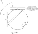
FIG. 14G is a representation of a twelfth example security camera system including the support body/camera subsystem mounted to the wall, with the support body configured to rotate around the globe camera system in order to switch from a ceiling-mount configuration and a wall-mount configuration. -
FIG. 15A is a representation of a thirteenth example security camera system including the support body/camera subsystem mounted to the ceiling. -
FIG. 15B is a representation of the thirteenth example security camera system including the support body/camera subsystem with the camera subsystem partially detached in preparation for changing the configuration to a wall mount. -
FIG. 15C is a representation of the thirteenth example security camera system including the support body/camera subsystem with the supporting bracket being swung to change to a wall mount. -
FIG. 15D is a representation of the thirteenth example security camera system including the support body/camera subsystem mounted to the wall. - Systems and methods in accordance with the present disclosure can provide a camera system that can maintain a level image when mounted to either a ceiling or wall, while using two axis-pan and tilt-functionality. As such, systems and methods in accordance with the present disclosure can reduce mechanical and electronic complexity as compared to security systems that may require motors or other adjustment mechanisms dedicated to moving in each of the pan (e.g., swivel the security camera horizontally from a fixed position), tilt (e.g., rotates up/down in a vertical plane), and rotate (e.g., so that the image can be leveled). Though not typically an issue with ceiling or pendant mounting of the security camera as pan movement rotates the security camera about the centroid and tilt movement adjusts the angle from the ceiling, a wall mounted security camera typically needs the rotation movement in order for the camera image to be level with the ground (since the panning or tilting may result in an image that is not level).
- In some embodiments, a security camera system in accordance with the present disclosure is configured to perform pan and tilt movements, but is not configured to perform rotational movements. In particular, the one or more motors or manual adjustment mechanism in the security camera system are configured to control movement of the camera, wherein the movement consists of pan movement and tilt movement (e.g., control in the pan direction and in the tilt direction) without providing any Z-axis gimbal rotation as required in conventional systems. Nevertheless, the security camera system can maintain a level image when mounted to a ceiling and also when mounted to a wall. The security camera system may include a support body and a camera subsystem. The support body includes a mechanical support body or mechanical support structure to support the camera and optionally electronics configured to control the camera. The camera subsystem includes the camera and optionally other electronics (such as a motor). In some embodiments, the security camera system is configured to maintain the pan axis of the camera in the vertical direction (e.g., parallel to the wall) when the security camera system is wall mounted. In some embodiments, the security camera system is configured to maintain the pan axis of the camera in the vertical direction when the security camera system is either wall mounted or ceiling mounted. For example, the security camera system, in both the ceiling-mount configuration and the wall-mount configuration, positions the camera is in the same orientation, whereas in the ceiling-mount configuration and the wall-mount configuration, positions the support body in different orientations. In this way, the pan rotation of the camera moves the image directly right or left for either wall or ceiling mounting, and tilt with direct up and down movement. Since there is no camera head rotation with either pan or tilt movements, the image of the camera remains level with the ground, thus avoiding the need for an additional mechanism to rotate the lens in the Z-axis to level the image.
- In various embodiments where the pan axis is in the vertical direction either for a wall mount or ceiling mount, the security camera system includes the support body and camera subsystem in at least two configurations: a wall-mounted configuration; and a ceiling-mounted configuration. In both the wall-mounted configuration and the ceiling-mounted configuration, the camera in the security camera system is configured so that the pan axis is always in the vertical direction. In order to maintain the pan axis in the vertical direction, the support body and the camera subsystem have different positions relative to one another when in the wall-mounted configuration or in the ceiling-mounted configuration. In particular, the security camera system has a wall-mounted relative position (the position of the support body relative to the camera subsystem when installed in the wall-mount) and a ceiling-mounted relative position (the position of the support body relative to the camera when installed in the wall-mount), with the wall-mounted relative position being different from the ceiling-mounted relative position. In this way, the same support body-camera subsystem may be used in either the wall-mounted configuration or in the ceiling-mounted configuration such that after installation, the camera (of the camera subsystem) is positioned so that the pan axis is in the vertical direction.
- In some embodiments, the support body may be rotated and/or flipped about an axis (such as rotated 180° about an axis as discussed below) relative to the camera subsystem in order to switch the security camera system from the wall-mounted configuration to the ceiling-mounted configuration, or from the ceiling-mounted configuration to the wall-mounted configuration. In some embodiments, the support body is rotated and/or flipped about the axis, and the camera subsystem remains stationary. In some embodiments, the camera subsystem is rotated and/or flipped about the axis, and the support body remains stationary. In some embodiments, both the support body and the camera subsystem are rotated and/or flipped about the axis. In various such embodiments, the camera (of the camera subsystem), when installed in either the wall-mounted configuration or in the ceiling-mounted configuration, is positioned such that the pan axis is in the vertical direction.
- The rotation and/or flipping may be performed in one of several ways. In some embodiments, the support body and the camera subsystem are rotated and/or flipped about the axis while the support body and the camera subsystem are connected to one another. For example, the connection point(s) between the support body and the camera subsystem may be configured for a swiveling motion (and optionally unlocking prior to the swiveling motion to allow for the swiveling movement and/or locking after the swiveling motion to disallow for the swiveling movement). In some embodiments, the support body and the camera subsystem are disconnected from one another, with one of the support body and the camera subsystem being flipped (such as the support body being flipped), and thereafter the support body and the camera subsystem are reattached to one another. For example, the support body and the camera subsystem may each have respective connectors through which to electronically communicate. One or both of the respective connectors may be double sided. For example, electronics in the camera subsystem may have a connector with a first side and a second side. On the first side, the connector may have a first set of connector pins, and on the second side, the connector may have a second set of connector pins. The support body may likewise have a connector with a set of pins. In the wall-mounted configuration, the support body may connect its set of pins with the first set of connector pins. Likewise, after flipping and/or rotating, for the ceiling-mounted configuration, the support body may connect its set of pins with the second set of connector pins. As another example, the support body may have a connector with a first side and a second side, with sets of pins on each of the first side and the second side. The camera subsystem may connect in the wall-mounted configuration with pins on the first side of the connector, and may connect in the ceiling-mounted configuration with pins on the second side of the connector.
- Thus, in some embodiments, for wall-mounted installation, the camera of the security camera system may have the pan axis always configured in the vertical direction (e.g., parallel to the wall on which the camera system is mounted or perpendicular to the ground). The support body has a surface that is configured to attach to the wall, with at least a part of the surface that is configured to attach to the wall being parallel to the vertical pan axis of the camera. As discussed above, the camera subsystem may include a motor for moving the camera about the pan axis. In some embodiments, the shaft of the motor is perpendicular to the ground. Further, in some embodiments, the belt for the motor, which moves the shaft, is perpendicular to the wall to which the security camera system is attached. In this way, the security camera system may only include one or more motors for panning and tilting movement, but not for any rotational movement of the camera in the security camera system. It will be appreciated that a wall may be a surface that is vertical by being substantially parallel to a gravity direction (e.g., a vector normal to the wall forms an angle with the gravity direction that is 90 degrees or within a threshold value of 90 degrees, the threshold value being less than or equal to 10 degrees). It will be appreciated that a ceiling may be a surface that is horizontal by being substantially perpendicular to the gravity direction (e.g., a vector normal to the ceiling forms an angle with the gravity direction that is 0 degrees or within a threshold value of 0 degrees, the threshold value being less than or equal to 10 degrees).
- Referring to the figures,
FIG. 1A is a block diagram 100 of a first example of thesupport body 120/camera subsystem 140 mounted on theceiling 110. The camera (not shown) in thecamera subsystem 140 includespan axis 135 that rotates in the pan direction such as rotating indirection 130 ordirection 132. As shown, thepan axis 135 for the camera is vertical (perpendicular to the ground and the ceiling 110). As illustrated inFIG. 1A , thesupport body 120 is coupled to thecamera subsystem 140 in a first orientation such that thepan axis 135 is vertical when thesupport body 120 is mounted on theceiling 110. -
FIG. 1B is a block diagram 150 of the first example of thesupport body 120/camera subsystem 140 mounted to thewall 160. As shown, thesame support body 120 used for the ceiling-mounted configuration (illustrated inFIG. 1A ) is used for the wall-mounted configuration (illustrated inFIG. 1B ); however, the portion of thesupport body 120 connected to the non-movable structure (either theceiling 110 or the wall 160) is different for the ceiling-mounted configuration versus the wall-mounted configuration. Further, the orientation of thesupport body 120 relative to thecamera subsystem 140 is different for the ceiling-mounted configuration versus the wall-mounted configuration, as discussed further below. -
FIGS. 1A-B illustrate the architecture that may eliminate the need to rotate the camera in the Z-axis. Motors (not shown) may be positioned in thesupport body 120 and/or thecamera subsystem 140 for adjusting the camera remotely in the pan and/or tilt positions. Further,FIGS. 1A-B illustrate that a single security camera system (withsupport body 120 and camera subsystem 140) may be used for ceiling and/or wall mounting. -
FIG. 2A is across-sectional view 200 of a second example of thesupport body 210/camera subsystem FIG. 2B is across-sectional view 250 of the second example of thesupport body 210/camera subsystem same support body 210/camera subsystem FIGS. 2A-B , thus enabling one product to encompass wall and ceiling mounted security camera applications (e.g., bullet-type camera and mini-dome-type camera applications). Thesupport body 210, which may contain the camera electronics, and may be positioned for the different installation options (wall mount and ceiling mount). As shown, there are two concentric caps, shown as 212 and 230. Support body 210 (and cap 212) may rotate around a 45degree axis 220 to select the wall or ceiling mounted configuration. In effect, thesupport body 210 rotates 180 degrees about the 45degree axis 220 to change from a ceiling-mounted configuration to a wall-mounted configuration, and vice-versa. The change in orientation ofsupport body 210 is illustrated byside 214 in the wall and ceiling-mounted configurations. Thecamera ball 244 may pan around thevertical axis 240, which is attached viacap 230 and always stays vertical. Thecamera ball 244 may also tilt orthogonally to the pan axis and may tilt along aspan 242, which is approximately 260°. - In this way, the camera security system may allow horizontal camera viewing (such as full viewing in all 360 degree directions) and below when ceiling mounted, such as to tilt along
span 242 discussed above. Also, the security camera system may allow camera viewing well above the horizon. The security camera system disclosed herein may be used with a variety of different types of cameras, including without limitation full camera/lens cover bubble or with a bubble-less flat clear disc lens cover, or none, as any of these may prove optimal to support higher resolution cameras such as 4K. The designs may be constructed to provide covertness to where the camera is pointing. Provisions for IR illuminators located beside the lens in separate compartments such as not to reflect or bleed into the lens may be incorporated. The 45degree axis 220 may be referred to as a 3rd axis to meet the 3 axis bid requirements. This security camera system may eliminate the traditional need for an analog video output often needed to connect to a local portable service monitor needed to point and level the camera image. In this way, the security camera system disclosed herein, with the feature of limited remote motor driven pan and tilt for easy installation and occasional re-positioning, is considerably different from a typical full speed PTZ or fixed dome camera. - For easy and universal installation,
support body 210 may have mounting holes to match standard electrical boxes, which may include: single/dual gang; 4S; octagon; UK single gang box; Euro gang box; etc. In addition,support body 210 may be designed for other direct mounting situations including recessed into surface, pendant cap, inside corner, outside corner, and pole mounting by having extra slots for straps or tabs, and having curved or angular edges to mate with these surfaces, as discussed further below. -
FIG. 3A is one of several possible 3-dimensional representation 300 of a third example of thesupport body 310/camera subsystem ceiling 110.FIG. 3B is a 3-dimensional representation 350 of the third example of thesupport body 310/camera subsystem wall 160. Thesupport body 310 may be rotated, such as in direction 340 (shown inFIG. 3A ) or in direction 360 (shown inFIG. 3B ) to change the configuration of the security camera system. For example, to change the security camera system from a ceiling mounted configuration to a wall-mounted configuration, thesupport body 310 may be rotated indirection 340, and rotation aboutaxis 322. As another example, to change the security camera system from a wall-mounted configuration to a ceiling mounted configuration, thesupport body 310 may be rotated indirection 360. As shown, thecamera ball 330 andarm 320 remain in the same orientation for both the ceiling-mounted configuration and the wall-mounted configuration. - The rotation of
support body 310 may be performed while support body is connected to camera subsystem. For example,support body 120 may be connected viapivot point 322 toarm 320 of camera subsystem. In this way,support body 120 may pivot atpivot point 322 where thesupport body 120 rotates relative to camera subsystem (e.g.,arm 320 andcamera ball 330 may rotate alongdirection camera ball 330 the camera may be cylindrical, oval (e.g., egg shaped), hemispherical, etc. in shape. Further,arm 320 may comprise a concentric cap or an arc (as shown), or may be disc shaped, hemispherical beanie shaped, or the like. -
FIG. 4A is across-sectional view 400 of a fourth example of thesupport body 410/camera subsystem FIG. 4B is across-sectional view 450 of the fourth example of thesupport body 410/camera subsystem -
Support body 410 may house electronics, motors, cables, mechanisms, and the like for the security camera system. In this regard,support body 410 may be larger thansupport body 210 illustrated inFIGS. 2A-B .FIGS. 4A-B illustratearc 412 as hemispherical or beanie shapes. Similar toFIGS. 2A-B ,arm 420 may connectcamera ball 244 to supportbody 410. Further,camera ball 244 may pan around thevertical axis 240, which always stays vertical. -
FIG. 5A is a 3-dimensional representation 500 of a fifth example of thesupport body 510/camera subsystem 520 mounted on the ceiling.FIG. 5B is a 3-dimensional representation 550 of the fifth example of thesupport body 510/camera subsystem 520 mounted to the wall. -
FIG. 6A is a schematic representation ofcamera security system 600 in a sixth example of the support body/camera subsystem mounted on the ceiling. In one implementation, the support body may comprisesupport structure 640, which may includeelectronics 602. In particular,surface 641 ofsupport structure 640 may be connected toceiling 110. As discussed further below,electronics 602 may comprise control electronics, such as a computing element (e.g., a processor, microcontroller, programmable gate array, or the like) and memory. In practice,electronics 602 may be configured to communicate with a central command system (not shown), which may be remotely located from the security camera system. The communications with the central command system may include any one, any combination, or all of: transmission of images (still and/or video) from the security camera system to the central command; transmission of status from the security camera system to the central command; control of the security camera system (e.g., the central command system may send a command to configure one or more aspects of the security camera system; the central command system may send a command to control movement of the security camera system (e.g., control thepan movement motor 620 for pan movement or control the tilt movement motor (not shown) for tilt movement). - The camera subsystem may comprise
motor subsystem 670,arm 630, and camera body 662 (within which is camera 660). Themotor subsystem 670 may comprise a housing to housecamera subsystem connector 610,pan movement motor 620,rotor 622,belt 624,gear 626, andshaft 628. Any of these elements may be housed completely within the housing of themotor subsystem 670. Alternatively, some of the elements, such ascamera subsystem connector 610, may be housed only partially within the housing of themotor subsystem 670, or exterior to the housing of themotor subsystem 670.Arm 630 includes two ends, end 632 connected or attached toshaft 628 and end 634 connected tocamera body 662. In one implementation,end 634 is permanently attached tocamera body 662. In practice,pan movement motor 620 movesrotor 622, which in turn movesbelt 624,gear 626,shaft 628, andarm 630 so thatcamera body 662 moves in the pan direction. Further, as shown, thecamera security system 600 inFIG. 6A is configured such that thecamera body 662 is configured to maintain the pan axis in the vertical direction when thecamera security system 600 is ceiling mounted. -
Camera body 662 may further include an internal tilt movement motor (not shown) in order to move a part ofcamera body 662. For example,portion 650 may remain stationary andportion 663 may move in the tilt direction. -
FIG. 6B is a schematic representation of the security camera system 680 (mounted to the wall) in the sixth example of the support body/camera subsystem. As shown, the orientation of the support body/camera subsystem is different than that depicted inFIG. 6A . In particular, support body, includingsupport structure 640, may be flipped so thatsurface 641 ofsupport structure 640 may be connected towall 160.Support body connector 604 of the support body may still be connected tocamera subsystem connector 610 of camera subsystem in either orientation depicted inFIGS. 6A-B . Further, as shown, thecamera security system 680 inFIG. 6B is configured such that thecamera body 662 is configured to maintain the pan axis in the vertical direction when thecamera security system 600 is wall mounted. -
FIG. 6C is a schematic representation of double sidedcamera subsystem connector 610. As discussed above, the orientation of support body/camera subsystem may change depending on whether the configuration is wall-mounted or ceiling mounted. In one implementation, one or more double-sided connectors may be used in order to allow for the different orientations of support body/camera subsystem. In particular,FIG. 6C illustrates thatcamera subsystem connector 610 of the camera subsystem may have two sets ofpins pins 686 on one side ofcamera subsystem connector 610 and second set of pins 689 on the opposite side ofcamera subsystem connector 610. Each set ofpins pins 686 is different than the second set ofpins 687. Specifically, the ordering is reversed so that the support body may be flipped while still maintaining the same connection to set ofpins 688 onsupport body connector 604 of support body. As shown pins 688 includes pins 690.1, 690.2, 690.3, 690.4, 690.5, 690.6, 690.7, and 690.8.Pins 688 are oriented so that upon connection to either first set ofpins 686 or second set ofpins 687, the pins from 688 may connect as follows: 690.1 to 684.1; 690.2 to 684.2; 690.3 to 684.3; 690.4 to 684.4; 690.5 to 684.5; 690.6 to 684.6; 690.7 to 684.7; and 690.8 to 684.8.Thus, the support body/camera subsystem may be configured either in a first orientation (such as the ceiling-mounted configuration) or in a second orientation (such as the wall-mounted configuration). Alternatively,camera subsystem connector 610 on camera subsystem may have two sets of pins, with a first set of pins on one side (ordered as follows: 690.1, 690.2, 690.3, 690.4, 690.5, 690.6, 690.7, and 690.8) and with a second set of pins on an opposite side (ordered as follows: 690.8, 690.7, 690.6, 690.5, 690.4, 690.3, 690.2, and 690.1). -
FIG. 7A is a schematic representation of acamera subsystem 700.Camera subsystem 700 includes anelectronics base housing 702 configured to housepan motor 704. The slant on electronics base housing 702 (such as the 45° slant) on the top allows theelectronics base housing 702 to be attached from the top or turned and attached from the side. This change at the 45° slant angle may be a movable joint or may simply separate and reattach to switch from ceiling mount to wall mount. As discussed above, if the pan axis is always vertical, then a rotate motor is not needed regardless of whether mounting to a ceiling or a wall. Likewise, tilt may always be an up or down movement. This will allow users to re-position the camera from the network video recorder (NVR) client by using the standard client GUI pan and tilt controls; therefore there is no need to add a remote rotate lens module command. - The security camera systems may not be full function PTZ (pan-tilt-zoom) dome, but simply the ability to pan and tilt. In this regard, the security camera system is not a full function PTZ, but a lower cost security camera system.
Pan motor 704 is connected to rotor, which is connected to gimbal 710 viagimbal connector 708.Gimbal 710 is connected, viaconnectors eyeball camera 718 on thegimbal 710 may move with thepan motor 704. In this regard,pan motor 704 may comprise a pan motorized mechanism that will rotate thegimbal 710. The tilt motor (not shown) is in theeyeball camera subsystem 716, and may tilt aboutconnectors FIG. 7A illustrateseyeball camera 718, other types of cameras, such as dome, cylinder, or bullet cameras, may be used. -
FIG. 7B is a schematic representation of a seventh examplesecurity camera system 720 including the support body/camera subsystem 700 (depicted inFIG. 7A ) mounted on theceiling 110.Camera subsystem 700 may be housed or connected tohousing 730, which is, in turn, is mounted tobase 732.Electronics 734 may be housed in base. -
FIG. 7C is a schematic representation of the seventh examplesecurity camera system 740 including the support body/camera subsystem 700 (depicted inFIG. 7A ) mounted to thewall 160. As illustrated, the orientation ofcamera subsystem 700 relative tohousing 730 is different from that depicted inFIG. 7B . -
FIG. 7D is a schematic representation of the seventh examplesecurity camera system 760 including the support body/bullet camera subsystem mounted to theceiling 110. Specifically,bullet camera subsystem 762 may be used in place ofeyeball camera subsystem 716. -
FIG. 8A is a block diagram of thecamera 802 mounted, via ashaped support body 810, to awall 160.Surface 826 ofsupport body 810 may contact a surface ofcamera 802. Further, one or more flat surfaces, such assurfaces wall 160. -
FIG. 8B is a block diagram of thecamera 802 mounted, via the shapedsupport body 810, to apost 821.Post 821 may contact one or more flat surfaces, such assurfaces support body 810. Alternatively, post 821 may contact one or more insets, such asinset 818 ofsupport body 810. -
Support body 810 may be configured to connect to different types of corners, such as to a first type of corner (e.g., an outside corner) and to a second type of corner (e.g., an inside corner). In particular,FIG. 8C is a block diagram of thecamera 802 mounted, via the shapedsupport body 810, to anoutside corner 842. Outsidecorner 842 may contact one or more insets in support body, such asinset 818 shaped to match the corner ofoutside corner 842. -
FIG. 8D is a block diagram of thecamera 802 mounted, via the shapedsupport body 810, to an inside corner 846. One or more sides ofsupport body 810, such assides 814, 822 (which may comprise flat edges), may contact one or more sides of inside corner 846. As illustrated, shapedsupport body 810 may include one or more shaped sides in order to connect with a plurality of objects, such as any one, any combination, or all of: wall; post; outside corner; and inside corner. -
FIG. 9A is a 3-dimensional representation of an eighth examplesecurity camera system 900 including thesupport body 906/camera subsystem 902 mounted on the ceiling. In particular, support body includes one ormore holes 908 on asurface 907 ofsupport body 906.Camera subsystem 902 includes amating piece 904 for mating with aninset 909 ofsupport body 906. -
FIG. 9B is a 3-dimensional representation of the eighth example security camera system including thesupport body 906/camera subsystem 902 with the support body being removed (at 920) and flipped 90° (at 910) to change to a wall mount. -
FIG. 9C is a 3-dimensional representation of the eighth example security camera system including thesupport body 906/camera subsystem 902 withmating piece 904 of thecamera subsystem 902 being inserted into theinset 909 of thesupport body 906, previously being flipped 90° (at 940) to change to the wall mount. Though not illustrating a face ofsupport body 906, which contacts thecamera subsystem 902 may be concave in order to seat the spherical portion of thecamera subsystem 902.FIG. 9D is a 3-dimensional representation of an eighth example security camera system including thesupport body 906/camera subsystem 902 mounted to the wall. -
FIG. 9E is a 3-dimensional representation of a first example of a supportingbracket 970 for corner mounting. Specifically, supportingbracket 970 may include one ormore sides U-shaped piece 974.Sides U-shaped piece 974 includesinset 975, which may mate withmating piece 904.FIG. 9F is a 3-dimensional representation of a second example of a supportingbracket 980 for the eighth example. As illustrated, sides 981, 982 of the supportingbracket 980 may seat in the corner of room. -
FIG. 10A is a representation of a ninth example security camera system including thesupport body 1010/camera subsystem 1020, with thesupport body 1010 being mounted to theceiling 110. Thesupport body 1010, which may comprise a mounting plate, may be screwed, such as viascrews ceiling 110, with thereceiver hole 1016 aligned to the camera viewing direction. -
FIG. 10B is a representation of the ninth example security camera system including thesupport body 1012/camera subsystem 1022, with thecamera subsystem 1022 being mounted to the support body 1010 (which is mounted to the ceiling 110). The camera wire may be run as needed. Further,portion 1026, which may comprise a male connector, ofcamera subsystem 1022, may be aligned withreceiver hole 1016. -
FIG. 10C is a representation of the ninth example security camera system including thesupport body 1012/camera subsystem 1020 mounted to theceiling 110. Asurface 1024 ofcamera subsystem 1020 is installed flush withsupport body 1010, so thatportion 1026 seat inreceiver hole 1016. In this way,camera 1022 ofcamera subsystem 1020 may be positioned. -
FIG. 11A is a representation of the ninth example security camera system including thesupport body 1010/camera subsystem 1020, with thesupport body 1010 being mounted to thewall 160 in configuration 1100.As shown, the orientation forsupport body 1010 may be flipped so thatreceiver hole 1016 is lined up withportion 1026. In particular, thesupport body 1010 is screwed intowall 160 withscrews receiver hole 1016 is at the top. -
FIG. 11B is a representation of the ninth example security camera system including thesupport body 1010/camera subsystem 1020, with thecamera subsystem 1020 being mounted to the support body 1010 (which is mounted to the wall 160). The camera wire may be run as needed. Further,portion 1026 ofcamera subsystem 1022, may be aligned withreceiver hole 1016. -
FIG. 11C is a representation of the ninth example security camera system including thesupport body 1010/camera subsystem 1020 mounted to thewall 160.Camera subsystem 1020 is installed flush withsupport body 1010, so thatportion 1026 seat inreceiver hole 1016. In this way,camera 1022 ofcamera subsystem 1020 may be positioned. -
FIG. 12A is a representation of a tenth example security camera system including thesupport body 1210/camera subsystem 1200, with the camera subsystem being mounted to the support body 1210 (which is mounted to the ceiling 110). An underside 1212 (opposite the side attached to the ceiling 110) ofsupport body 1210 may comprise aninset 1214 configured to receive aprotrusion 1202. Further,underside 1212 may have a curved surface configured to mate with a roundedupper side 1204 ofcamera subsystem 1200. -
FIG. 12B is a representation of the tenth example security camera system including thesupport body 1210/camera subsystem 1200 mounted to theceiling 110 for configuration ofcamera 1206. -
FIG. 13A is a representation of the tenth example security camera system including thesupport body 1210/camera subsystem 1200, with thecamera subsystem 1200 being mounted to the support body 1210 (which is mounted to the wall 160). As shown,support body 1210 is flipped withinset 1214 facing toward theceiling 110.Underside 1212, which has a curved surface, may mate with a rounded side ofcamera subsystem 1200.FIG. 13B is a representation of the tenth example security camera system including thesupport body 1210/camera subsystem 1200 mounted to thewall 160. -
FIG. 14A is a representation of an eleventh examplesecurity camera system 1400 including thesupport body camera subsystem 1430 mounted to theceiling 110.Support body camera subsystem 1430 or may be connectable tocamera subsystem 1430. -
FIG. 14B is a representation of the eleventh example security camera system including thesupport body camera subsystem 1430 with the supportingbracket 1410 being swung to change to a wall mount, andcamera bracket 1420 maintaining the connection withcamera subsystem 1430. As shown, supportingbracket 1410 is hinged withcamera bracket 1420. -
FIG. 14C is arepresentation 1440 of the eleventh example security camera system including thesupport body camera subsystem 1430 mounted to thewall 160, with supportingbracket 1410 being connected towall 160. -
FIG. 14D is anotherexample representation 1460 illustrating rotation (e.g., swiveling) similar toFIGS. 2 ,3 ,4 ,6 and7 above, rather than flipping or separating/reattaching. -
FIG. 14E is arepresentation 1470 of a twelfth example of a supporting bracket that is configured to swivel in order to change between a ceiling-mount configuration and a wall-mount configuration. -
FIG. 14F is a general illustration abracket 1480 that shows the movements of pan, tilt, and rotate operations. -
FIG. 14G is a representation of a twelfth examplesecurity camera system 1490 including the support body/camera subsystem mounted to the wall, with the support body configured to rotate around the globe camera system in order to switch from a ceiling-mount configuration and a wall-mount configuration. -
FIG. 15A is a representation of a thirteenth examplesecurity camera system 1500 including thesupport body camera subsystem 1020 mounted to theceiling 110.FIG. 15B is a representation of the thirteenth example security camera system including thesupport body camera subsystem 1020 with supportingbracket 1510 being swung fromcamera bracket 1520 thereby partially detachingcamera subsystem 1020 in preparation for changing the configuration to a wall mount. -
FIG. 15C is a representation of the thirteenth example security camera system including thesupport body camera subsystem 1020 with the supportingbracket 1510 being swung 1542 to change to a wall mount. Specifically, supportingbracket 1510 is rotated to align with the wall, such as rotated 270°.FIG. 15D is a representation of the thirteenth example security camera system including thesupport body camera subsystem 1020 mounted to the wall. In particular, supportingbracket 1510 is affixed to wall 160 withscrews - The construction and arrangement of the systems and methods as shown in the various exemplary embodiments are illustrative only. Although only example embodiments have been described in detail in this disclosure, many modifications are possible (e.g., variations in sizes, dimensions, structures, shapes and proportions of the various elements, values of parameters, mounting arrangements, use of materials, colors, orientations, etc.). For example, the position of elements can be reversed or otherwise varied and the nature or number of discrete elements or positions can be altered or varied. Accordingly, such modifications are intended to be included within the scope of the present disclosure. The order or sequence of any process or method steps can be varied or re-sequenced according to alternative embodiments. Other substitutions, modifications, changes, and omissions can be made in the design, operating conditions and arrangement of the examples provided without departing from the scope of the present disclosure.
Claims (15)
- A camera system comprising:a support body;a camera; andone or more motors or manual adjustment mechanism configured to control movement of the camera, wherein the movement of the camera consists of control in a pan direction and in a tilt direction,wherein the support body and the camera connect in a ceiling-mount configuration for connection of the camera system to a ceiling and a wall-mount configuration for connection of the camera system to a wall,wherein the ceiling-mount configuration is different from the wall-mount configuration, andwherein in both the ceiling-mount configuration and the wall-mount configuration, a pan axis of the camera is always in a vertical direction parallel to the wall.
- The camera system of claim 1, wherein, in both the ceiling-mount configuration and the wall-mount configuration, the camera is in a same orientation; and
wherein, in the ceiling-mount configuration and the wall-mount configuration, the support body is in different orientations. - The camera system of claim 1 or, in particular, claim 2, wherein, in the wall-mount configuration, the support body is rotated 180° and flipped relative to the orientation of the support body in the ceiling-mount configuration.
- The camera system of any one of the preceding claims, in particular claim 3, whereina) the support body and the camera are configured to rotate relative to one another to transition from the ceiling-mount configuration to the wall-mount configuration or vice-versa while the support body is attached to the camera, and/orb) the support body and the camera are configured to disconnect from one another and reconnect after rotation 180° and flipping relative to one another.
- The camera system of any one of the preceding claims, in particular claim 4, wherein the support body comprises a support body connector;
wherein a camera subsystem comprises the camera and a camera subsystem connector;
wherein one or both of the support body connector or the camera subsystem connector comprises a double sided connector;
wherein, in the ceiling-mounted configuration, the support body and the camera subsystem electrically connect via a first side of the double sided connector; and wherein, in the wall-mounted configuration, the support body and the camera subsystem electrically connect via a second side of the double sided connector, wherein the camera subsystem connector preferably comprises the double sided connector. - The camera system of any one of the previous claims, further comprising a camera subsystem comprising the camera, a motor, and a camera subsystem connector; and wherein the support body comprises electronics and a support body connector, the electronics configured to control the motor.
- The camera system of claim 6, wherein the camera subsystem includes a shaft configured to move via the motor and an arm connecting the shaft to the camera; and wherein the shaft is in a same orientation in both the ceiling-mount configuration and the wall-mount configuration, wherein the shaft is preferably always in the vertical direction.
- The camera system of any one of the previous claims, wherein the support body comprises an inset for contact with a first type of corner and comprises one or more flat edges for contact with a second type of corner.
- The camera system of any one of the previous claims, further comprising a camera subsystem comprising the camera and a motor or manual adjustment mechanism; wherein the support body comprises a first portion of the support body and a second portion of the support body;
wherein the first portion of the support body is connected to the second portion of the support body via a hinge;
wherein the second portion of the support body is connected to the camera subsystem; and
wherein the first portion of the support body is configured to connect to the wall or to the ceiling. - The camera system of any one of the previous claims, wherein the one or more motors are configured to control movement of the camera.
- A camera system comprising:a support body comprising a surface configured to connect to a wall;a camera; andone or more motors or manual adjustment mechanism configured to control movement of the camera, wherein the movement of the camera consists of control in a pan direction and in a tilt direction and wherein the movement of the camera does not include any rotational movement,wherein a pan axis of the camera is always in a vertical direction parallel to the wall, andwherein the surface of the support body is parallel to the pan axis of the camera.
- The camera system of any one of the preceding claims, in particular claim 11, further comprising a shaft configured to move via the motor and an arm connecting the shaft to the camera;
wherein movement of the shaft is configured to move the camera in the pan direction; and
wherein the shaft is coaxial with the pan axis and in the vertical direction, preferably further comprising a belt translating motion from the motor to the shaft; and
wherein the belt is perpendicular to the wall. - The camera system of any one of the preceding claims, in particular claim 12, wherein the camera is housed in a housing;
wherein the arm is fixedly connected at a first end to the shaft; and
wherein the arm is fixedly connected at a second end to the housing. - The camera system of any one of the preceding claims, in particular claim 13, wherein the support body comprises a support body connector;
further comprising a camera subsystem comprises the camera and a camera subsystem connector; and
wherein one or both of the support body connector or the camera subsystem connector comprises a double sided connector, wherein the camera subsystem connector preferably comprises the double sided connector. - The camera system of any one of the preceding claims, in particular claim 11, wherein the one or more motors are configured to control movement of the camera.
Applications Claiming Priority (1)
| Application Number | Priority Date | Filing Date | Title |
|---|---|---|---|
| US15/959,860 US11134200B2 (en) | 2018-04-23 | 2018-04-23 | Two axis pan tilt camera system configured to maintain a level image when wall or ceiling mounted |
Publications (3)
| Publication Number | Publication Date |
|---|---|
| EP3562140A2 true EP3562140A2 (en) | 2019-10-30 |
| EP3562140A3 EP3562140A3 (en) | 2019-12-18 |
| EP3562140B1 EP3562140B1 (en) | 2022-02-09 |
Family
ID=66248600
Family Applications (1)
| Application Number | Title | Priority Date | Filing Date |
|---|---|---|---|
| EP19170575.5A Active EP3562140B1 (en) | 2018-04-23 | 2019-04-23 | Two axis pan tilt camera system configured to maintain a level image when wall or ceiling mounted |
Country Status (2)
| Country | Link |
|---|---|
| US (1) | US11134200B2 (en) |
| EP (1) | EP3562140B1 (en) |
Cited By (2)
| Publication number | Priority date | Publication date | Assignee | Title |
|---|---|---|---|---|
| CN111212266A (en) * | 2020-01-15 | 2020-05-29 | 陕西全安能源科技有限公司 | Intelligent monitoring system and method for power distribution room |
| CN111637345A (en) * | 2020-06-08 | 2020-09-08 | 杭州雅凇科技有限公司 | Internet monitoring anti-theft device for electronic commerce |
Families Citing this family (4)
| Publication number | Priority date | Publication date | Assignee | Title |
|---|---|---|---|---|
| EP3780573B1 (en) * | 2018-04-11 | 2023-10-18 | Hangzhou Hikvision Digital Technology Co., Ltd. | Multi-view camera and lens adjustment device |
| CN113225473B (en) * | 2020-02-05 | 2022-07-08 | 浙江大华技术股份有限公司 | Method, apparatus, device and medium for auto-focusing |
| US11825230B2 (en) * | 2020-02-14 | 2023-11-21 | Canon Kabushiki Kaisha | Imaging apparatus and storage medium |
| US11743589B2 (en) * | 2021-02-10 | 2023-08-29 | AuTurn | Device for autonomous tracking |
Family Cites Families (15)
| Publication number | Priority date | Publication date | Assignee | Title |
|---|---|---|---|---|
| US5028997A (en) * | 1989-07-20 | 1991-07-02 | Elbex Video Kabushiki Kaisha | Television camera apparatus |
| US6015123A (en) | 1998-03-03 | 2000-01-18 | Sensormatic Electronics Corporation | Mounting bracket for a camera base |
| JP2001346074A (en) * | 2000-06-02 | 2001-12-14 | Mitsubishi Electric Corp | Device for supporting camera |
| JP4445322B2 (en) | 2004-05-07 | 2010-04-07 | パナソニック株式会社 | Camera mounting device |
| JP2008502984A (en) | 2004-06-17 | 2008-01-31 | ウォレテックス マイクロエレクトロニクス リミティッド | Improved connectors and devices for flexible connectable computer systems |
| US7425101B2 (en) * | 2006-05-26 | 2008-09-16 | Yi-Jen Cheng | Image adjusting assembly for a monitoring camera |
| CN101098404B (en) | 2006-06-30 | 2011-10-26 | 三洋电机株式会社 | Surveillance camera |
| JP4977419B2 (en) | 2006-08-10 | 2012-07-18 | 三洋電機株式会社 | Surveillance camera |
| US7614804B2 (en) * | 2006-08-29 | 2009-11-10 | Nuvico, Inc. | Security camera |
| JP4800281B2 (en) | 2007-09-28 | 2011-10-26 | パナソニック株式会社 | Camera device |
| US20090290023A1 (en) | 2008-05-23 | 2009-11-26 | Jason Guy Lefort | Self contained wall mountable surveillance and security system |
| US9441781B2 (en) * | 2011-11-14 | 2016-09-13 | Motrr Llc | Positioning apparatus for photographic and video imaging and recording and system utilizing same |
| US9635224B2 (en) * | 2014-04-18 | 2017-04-25 | Alarm.Com Incorporated | Pan and tilt camera with robotic movement |
| US9458963B1 (en) * | 2015-03-31 | 2016-10-04 | Swiftcam Technologies Group Company Limited | 360-degree gimbal system |
| CN207634925U (en) * | 2017-06-20 | 2018-07-20 | 深圳市道通智能航空技术有限公司 | A kind of holder and the camera assembly with this holder |
-
2018
- 2018-04-23 US US15/959,860 patent/US11134200B2/en active Active
-
2019
- 2019-04-23 EP EP19170575.5A patent/EP3562140B1/en active Active
Non-Patent Citations (1)
| Title |
|---|
| None |
Cited By (2)
| Publication number | Priority date | Publication date | Assignee | Title |
|---|---|---|---|---|
| CN111212266A (en) * | 2020-01-15 | 2020-05-29 | 陕西全安能源科技有限公司 | Intelligent monitoring system and method for power distribution room |
| CN111637345A (en) * | 2020-06-08 | 2020-09-08 | 杭州雅凇科技有限公司 | Internet monitoring anti-theft device for electronic commerce |
Also Published As
| Publication number | Publication date |
|---|---|
| EP3562140B1 (en) | 2022-02-09 |
| US11134200B2 (en) | 2021-09-28 |
| US20190327420A1 (en) | 2019-10-24 |
| EP3562140A3 (en) | 2019-12-18 |
Similar Documents
| Publication | Publication Date | Title |
|---|---|---|
| EP3562140B1 (en) | Two axis pan tilt camera system configured to maintain a level image when wall or ceiling mounted | |
| US9690172B2 (en) | Omnidirectional user configurable multi-camera housing | |
| JP4507428B2 (en) | Camera device | |
| US7306383B2 (en) | Compound dome window for a surveillance camera | |
| US20080008467A1 (en) | Omni-directional surveillance network video camera | |
| EP3220036B1 (en) | A ball joint | |
| US7661890B2 (en) | Imagine apparatus with rotatable lens barrel | |
| WO2005076068A1 (en) | Dome type camera | |
| CN112422843A (en) | Multi-camera device and image capturing system including the same | |
| KR100724306B1 (en) | Bracket for Closed-Circuit Television | |
| KR101011269B1 (en) | Dome Camera | |
| JP4312880B2 (en) | TV camera | |
| JP7362363B2 (en) | Imaging device | |
| EP0990834A1 (en) | Camera mounting | |
| US6130704A (en) | Controlling movement of video surveillance cameras | |
| WO2020024123A1 (en) | Gimbal and gimbal system | |
| EP3817372B1 (en) | Triaxial dome-type surveillance camera | |
| KR101576920B1 (en) | Surveillance Camera to prevent screen blanking | |
| JP2023108568A (en) | Surveillance camera | |
| US20220223016A1 (en) | Image capturing apparatus | |
| JP2008141232A (en) | Lens barrel rotation type imaging apparatus | |
| CN217470083U (en) | Mounting structure of barrel-type camera | |
| CN216565304U (en) | Video camera | |
| JP5623450B2 (en) | Dome type surveillance camera | |
| JP2024036842A (en) | Imaging device |
Legal Events
| Date | Code | Title | Description |
|---|---|---|---|
| PUAI | Public reference made under article 153(3) epc to a published international application that has entered the european phase |
Free format text: ORIGINAL CODE: 0009012 |
|
| STAA | Information on the status of an ep patent application or granted ep patent |
Free format text: STATUS: THE APPLICATION HAS BEEN PUBLISHED |
|
| AK | Designated contracting states |
Kind code of ref document: A2 Designated state(s): AL AT BE BG CH CY CZ DE DK EE ES FI FR GB GR HR HU IE IS IT LI LT LU LV MC MK MT NL NO PL PT RO RS SE SI SK SM TR |
|
| AX | Request for extension of the european patent |
Extension state: BA ME |
|
| PUAL | Search report despatched |
Free format text: ORIGINAL CODE: 0009013 |
|
| AK | Designated contracting states |
Kind code of ref document: A3 Designated state(s): AL AT BE BG CH CY CZ DE DK EE ES FI FR GB GR HR HU IE IS IT LI LT LU LV MC MK MT NL NO PL PT RO RS SE SI SK SM TR |
|
| AX | Request for extension of the european patent |
Extension state: BA ME |
|
| RIC1 | Information provided on ipc code assigned before grant |
Ipc: F16M 13/02 20060101ALI20191108BHEP Ipc: G03B 17/02 20060101ALI20191108BHEP Ipc: G08B 13/196 20060101ALI20191108BHEP Ipc: F16M 11/04 20060101ALI20191108BHEP Ipc: H04N 7/18 20060101ALI20191108BHEP Ipc: H04N 5/232 20060101ALI20191108BHEP Ipc: H04N 5/225 20060101AFI20191108BHEP |
|
| STAA | Information on the status of an ep patent application or granted ep patent |
Free format text: STATUS: REQUEST FOR EXAMINATION WAS MADE |
|
| 17P | Request for examination filed |
Effective date: 20200618 |
|
| RBV | Designated contracting states (corrected) |
Designated state(s): AL AT BE BG CH CY CZ DE DK EE ES FI FR GB GR HR HU IE IS IT LI LT LU LV MC MK MT NL NO PL PT RO RS SE SI SK SM TR |
|
| STAA | Information on the status of an ep patent application or granted ep patent |
Free format text: STATUS: EXAMINATION IS IN PROGRESS |
|
| STAA | Information on the status of an ep patent application or granted ep patent |
Free format text: STATUS: EXAMINATION IS IN PROGRESS |
|
| 17Q | First examination report despatched |
Effective date: 20201209 |
|
| RIC1 | Information provided on ipc code assigned before grant |
Ipc: G03B 17/56 20210101ALI20210730BHEP Ipc: F16M 11/20 20060101ALI20210730BHEP Ipc: F16M 11/18 20060101ALI20210730BHEP Ipc: F16M 11/12 20060101ALI20210730BHEP Ipc: F16M 11/04 20060101ALI20210730BHEP Ipc: F16M 13/02 20060101ALI20210730BHEP Ipc: H04N 5/232 20060101ALI20210730BHEP Ipc: H04N 7/18 20060101ALI20210730BHEP Ipc: G08B 13/196 20060101ALI20210730BHEP Ipc: G03B 17/02 20210101ALI20210730BHEP Ipc: H04N 5/225 20060101AFI20210730BHEP |
|
| GRAP | Despatch of communication of intention to grant a patent |
Free format text: ORIGINAL CODE: EPIDOSNIGR1 |
|
| STAA | Information on the status of an ep patent application or granted ep patent |
Free format text: STATUS: GRANT OF PATENT IS INTENDED |
|
| INTG | Intention to grant announced |
Effective date: 20210910 |
|
| RAP3 | Party data changed (applicant data changed or rights of an application transferred) |
Owner name: SENSORMATIC ELECTRONICS, LLC |
|
| RIN1 | Information on inventor provided before grant (corrected) |
Inventor name: SIU, PATRICK Inventor name: MILLER, CHANNING EVERET Inventor name: SCHIELTZ, STEVEN W. |
|
| GRAS | Grant fee paid |
Free format text: ORIGINAL CODE: EPIDOSNIGR3 |
|
| GRAA | (expected) grant |
Free format text: ORIGINAL CODE: 0009210 |
|
| STAA | Information on the status of an ep patent application or granted ep patent |
Free format text: STATUS: THE PATENT HAS BEEN GRANTED |
|
| AK | Designated contracting states |
Kind code of ref document: B1 Designated state(s): AL AT BE BG CH CY CZ DE DK EE ES FI FR GB GR HR HU IE IS IT LI LT LU LV MC MK MT NL NO PL PT RO RS SE SI SK SM TR |
|
| REG | Reference to a national code |
Ref country code: GB Ref legal event code: FG4D |
|
| REG | Reference to a national code |
Ref country code: CH Ref legal event code: EP Ref country code: AT Ref legal event code: REF Ref document number: 1468228 Country of ref document: AT Kind code of ref document: T Effective date: 20220215 |
|
| REG | Reference to a national code |
Ref country code: IE Ref legal event code: FG4D |
|
| REG | Reference to a national code |
Ref country code: DE Ref legal event code: R096 Ref document number: 602019011405 Country of ref document: DE |
|
| REG | Reference to a national code |
Ref country code: LT Ref legal event code: MG9D |
|
| REG | Reference to a national code |
Ref country code: NL Ref legal event code: MP Effective date: 20220209 |
|
| REG | Reference to a national code |
Ref country code: AT Ref legal event code: MK05 Ref document number: 1468228 Country of ref document: AT Kind code of ref document: T Effective date: 20220209 |
|
| PG25 | Lapsed in a contracting state [announced via postgrant information from national office to epo] |
Ref country code: SE Free format text: LAPSE BECAUSE OF FAILURE TO SUBMIT A TRANSLATION OF THE DESCRIPTION OR TO PAY THE FEE WITHIN THE PRESCRIBED TIME-LIMIT Effective date: 20220209 Ref country code: RS Free format text: LAPSE BECAUSE OF FAILURE TO SUBMIT A TRANSLATION OF THE DESCRIPTION OR TO PAY THE FEE WITHIN THE PRESCRIBED TIME-LIMIT Effective date: 20220209 Ref country code: PT Free format text: LAPSE BECAUSE OF FAILURE TO SUBMIT A TRANSLATION OF THE DESCRIPTION OR TO PAY THE FEE WITHIN THE PRESCRIBED TIME-LIMIT Effective date: 20220609 Ref country code: NO Free format text: LAPSE BECAUSE OF FAILURE TO SUBMIT A TRANSLATION OF THE DESCRIPTION OR TO PAY THE FEE WITHIN THE PRESCRIBED TIME-LIMIT Effective date: 20220509 Ref country code: NL Free format text: LAPSE BECAUSE OF FAILURE TO SUBMIT A TRANSLATION OF THE DESCRIPTION OR TO PAY THE FEE WITHIN THE PRESCRIBED TIME-LIMIT Effective date: 20220209 Ref country code: LT Free format text: LAPSE BECAUSE OF FAILURE TO SUBMIT A TRANSLATION OF THE DESCRIPTION OR TO PAY THE FEE WITHIN THE PRESCRIBED TIME-LIMIT Effective date: 20220209 Ref country code: HR Free format text: LAPSE BECAUSE OF FAILURE TO SUBMIT A TRANSLATION OF THE DESCRIPTION OR TO PAY THE FEE WITHIN THE PRESCRIBED TIME-LIMIT Effective date: 20220209 Ref country code: ES Free format text: LAPSE BECAUSE OF FAILURE TO SUBMIT A TRANSLATION OF THE DESCRIPTION OR TO PAY THE FEE WITHIN THE PRESCRIBED TIME-LIMIT Effective date: 20220209 Ref country code: BG Free format text: LAPSE BECAUSE OF FAILURE TO SUBMIT A TRANSLATION OF THE DESCRIPTION OR TO PAY THE FEE WITHIN THE PRESCRIBED TIME-LIMIT Effective date: 20220509 |
|
| PG25 | Lapsed in a contracting state [announced via postgrant information from national office to epo] |
Ref country code: PL Free format text: LAPSE BECAUSE OF FAILURE TO SUBMIT A TRANSLATION OF THE DESCRIPTION OR TO PAY THE FEE WITHIN THE PRESCRIBED TIME-LIMIT Effective date: 20220209 Ref country code: LV Free format text: LAPSE BECAUSE OF FAILURE TO SUBMIT A TRANSLATION OF THE DESCRIPTION OR TO PAY THE FEE WITHIN THE PRESCRIBED TIME-LIMIT Effective date: 20220209 Ref country code: GR Free format text: LAPSE BECAUSE OF FAILURE TO SUBMIT A TRANSLATION OF THE DESCRIPTION OR TO PAY THE FEE WITHIN THE PRESCRIBED TIME-LIMIT Effective date: 20220510 Ref country code: FI Free format text: LAPSE BECAUSE OF FAILURE TO SUBMIT A TRANSLATION OF THE DESCRIPTION OR TO PAY THE FEE WITHIN THE PRESCRIBED TIME-LIMIT Effective date: 20220209 Ref country code: AT Free format text: LAPSE BECAUSE OF FAILURE TO SUBMIT A TRANSLATION OF THE DESCRIPTION OR TO PAY THE FEE WITHIN THE PRESCRIBED TIME-LIMIT Effective date: 20220209 |
|
| PG25 | Lapsed in a contracting state [announced via postgrant information from national office to epo] |
Ref country code: IS Free format text: LAPSE BECAUSE OF FAILURE TO SUBMIT A TRANSLATION OF THE DESCRIPTION OR TO PAY THE FEE WITHIN THE PRESCRIBED TIME-LIMIT Effective date: 20220609 |
|
| PG25 | Lapsed in a contracting state [announced via postgrant information from national office to epo] |
Ref country code: SM Free format text: LAPSE BECAUSE OF FAILURE TO SUBMIT A TRANSLATION OF THE DESCRIPTION OR TO PAY THE FEE WITHIN THE PRESCRIBED TIME-LIMIT Effective date: 20220209 Ref country code: SK Free format text: LAPSE BECAUSE OF FAILURE TO SUBMIT A TRANSLATION OF THE DESCRIPTION OR TO PAY THE FEE WITHIN THE PRESCRIBED TIME-LIMIT Effective date: 20220209 Ref country code: RO Free format text: LAPSE BECAUSE OF FAILURE TO SUBMIT A TRANSLATION OF THE DESCRIPTION OR TO PAY THE FEE WITHIN THE PRESCRIBED TIME-LIMIT Effective date: 20220209 Ref country code: EE Free format text: LAPSE BECAUSE OF FAILURE TO SUBMIT A TRANSLATION OF THE DESCRIPTION OR TO PAY THE FEE WITHIN THE PRESCRIBED TIME-LIMIT Effective date: 20220209 Ref country code: DK Free format text: LAPSE BECAUSE OF FAILURE TO SUBMIT A TRANSLATION OF THE DESCRIPTION OR TO PAY THE FEE WITHIN THE PRESCRIBED TIME-LIMIT Effective date: 20220209 Ref country code: CZ Free format text: LAPSE BECAUSE OF FAILURE TO SUBMIT A TRANSLATION OF THE DESCRIPTION OR TO PAY THE FEE WITHIN THE PRESCRIBED TIME-LIMIT Effective date: 20220209 |
|
| REG | Reference to a national code |
Ref country code: DE Ref legal event code: R097 Ref document number: 602019011405 Country of ref document: DE |
|
| REG | Reference to a national code |
Ref country code: DE Ref legal event code: R079 Ref document number: 602019011405 Country of ref document: DE Free format text: PREVIOUS MAIN CLASS: H04N0005225000 Ipc: H04N0023000000 |
|
| PG25 | Lapsed in a contracting state [announced via postgrant information from national office to epo] |
Ref country code: AL Free format text: LAPSE BECAUSE OF FAILURE TO SUBMIT A TRANSLATION OF THE DESCRIPTION OR TO PAY THE FEE WITHIN THE PRESCRIBED TIME-LIMIT Effective date: 20220209 |
|
| REG | Reference to a national code |
Ref country code: CH Ref legal event code: PL |
|
| PLBE | No opposition filed within time limit |
Free format text: ORIGINAL CODE: 0009261 |
|
| STAA | Information on the status of an ep patent application or granted ep patent |
Free format text: STATUS: NO OPPOSITION FILED WITHIN TIME LIMIT |
|
| REG | Reference to a national code |
Ref country code: BE Ref legal event code: MM Effective date: 20220430 |
|
| 26N | No opposition filed |
Effective date: 20221110 |
|
| PG25 | Lapsed in a contracting state [announced via postgrant information from national office to epo] |
Ref country code: MC Free format text: LAPSE BECAUSE OF FAILURE TO SUBMIT A TRANSLATION OF THE DESCRIPTION OR TO PAY THE FEE WITHIN THE PRESCRIBED TIME-LIMIT Effective date: 20220209 Ref country code: LU Free format text: LAPSE BECAUSE OF NON-PAYMENT OF DUE FEES Effective date: 20220423 Ref country code: LI Free format text: LAPSE BECAUSE OF NON-PAYMENT OF DUE FEES Effective date: 20220430 Ref country code: CH Free format text: LAPSE BECAUSE OF NON-PAYMENT OF DUE FEES Effective date: 20220430 |
|
| PG25 | Lapsed in a contracting state [announced via postgrant information from national office to epo] |
Ref country code: SI Free format text: LAPSE BECAUSE OF FAILURE TO SUBMIT A TRANSLATION OF THE DESCRIPTION OR TO PAY THE FEE WITHIN THE PRESCRIBED TIME-LIMIT Effective date: 20220209 Ref country code: BE Free format text: LAPSE BECAUSE OF NON-PAYMENT OF DUE FEES Effective date: 20220430 |
|
| PG25 | Lapsed in a contracting state [announced via postgrant information from national office to epo] |
Ref country code: IE Free format text: LAPSE BECAUSE OF NON-PAYMENT OF DUE FEES Effective date: 20220423 |
|
| PG25 | Lapsed in a contracting state [announced via postgrant information from national office to epo] |
Ref country code: IT Free format text: LAPSE BECAUSE OF FAILURE TO SUBMIT A TRANSLATION OF THE DESCRIPTION OR TO PAY THE FEE WITHIN THE PRESCRIBED TIME-LIMIT Effective date: 20220209 |
|
| PGFP | Annual fee paid to national office [announced via postgrant information from national office to epo] |
Ref country code: FR Payment date: 20230421 Year of fee payment: 5 Ref country code: DE Payment date: 20230427 Year of fee payment: 5 |
|
| PGFP | Annual fee paid to national office [announced via postgrant information from national office to epo] |
Ref country code: GB Payment date: 20230418 Year of fee payment: 5 |
|
| PG25 | Lapsed in a contracting state [announced via postgrant information from national office to epo] |
Ref country code: HU Free format text: LAPSE BECAUSE OF FAILURE TO SUBMIT A TRANSLATION OF THE DESCRIPTION OR TO PAY THE FEE WITHIN THE PRESCRIBED TIME-LIMIT; INVALID AB INITIO Effective date: 20190423 |