EP3561965B1 - Waterproof connection apparatus for electronic equipment, and electronic equipment - Google Patents
Waterproof connection apparatus for electronic equipment, and electronic equipment Download PDFInfo
- Publication number
- EP3561965B1 EP3561965B1 EP19181015.9A EP19181015A EP3561965B1 EP 3561965 B1 EP3561965 B1 EP 3561965B1 EP 19181015 A EP19181015 A EP 19181015A EP 3561965 B1 EP3561965 B1 EP 3561965B1
- Authority
- EP
- European Patent Office
- Prior art keywords
- supporting portion
- electronic equipment
- connection apparatus
- outer case
- ring
- Prior art date
- Legal status (The legal status is an assumption and is not a legal conclusion. Google has not performed a legal analysis and makes no representation as to the accuracy of the status listed.)
- Active
Links
- 238000007789 sealing Methods 0.000 claims description 84
- 229920005989 resin Polymers 0.000 claims description 31
- 239000011347 resin Substances 0.000 claims description 31
- 239000013013 elastic material Substances 0.000 claims description 8
- 239000002184 metal Substances 0.000 claims description 6
- 238000013459 approach Methods 0.000 claims description 5
- 238000012545 processing Methods 0.000 claims description 2
- 239000000463 material Substances 0.000 description 23
- 238000012986 modification Methods 0.000 description 10
- 230000004048 modification Effects 0.000 description 10
- 238000000465 moulding Methods 0.000 description 10
- XLYOFNOQVPJJNP-UHFFFAOYSA-N water Substances O XLYOFNOQVPJJNP-UHFFFAOYSA-N 0.000 description 10
- 238000003780 insertion Methods 0.000 description 9
- 230000037431 insertion Effects 0.000 description 9
- 238000004519 manufacturing process Methods 0.000 description 7
- 229920001971 elastomer Polymers 0.000 description 5
- 238000001746 injection moulding Methods 0.000 description 5
- 230000002950 deficient Effects 0.000 description 4
- 238000013461 design Methods 0.000 description 4
- 230000013011 mating Effects 0.000 description 3
- 238000000034 method Methods 0.000 description 3
- 239000000806 elastomer Substances 0.000 description 2
- 230000002093 peripheral effect Effects 0.000 description 2
- 229920005668 polycarbonate resin Polymers 0.000 description 2
- 239000004431 polycarbonate resin Substances 0.000 description 2
- 238000005549 size reduction Methods 0.000 description 2
- 229920000122 acrylonitrile butadiene styrene Polymers 0.000 description 1
- 230000003247 decreasing effect Effects 0.000 description 1
- 230000000694 effects Effects 0.000 description 1
- 238000010295 mobile communication Methods 0.000 description 1
- 239000004033 plastic Substances 0.000 description 1
- 229920003023 plastic Polymers 0.000 description 1
- 230000001681 protective effect Effects 0.000 description 1
- 238000005476 soldering Methods 0.000 description 1
Images


Classifications
-
- H—ELECTRICITY
- H01—ELECTRIC ELEMENTS
- H01R—ELECTRICALLY-CONDUCTIVE CONNECTIONS; STRUCTURAL ASSOCIATIONS OF A PLURALITY OF MUTUALLY-INSULATED ELECTRICAL CONNECTING ELEMENTS; COUPLING DEVICES; CURRENT COLLECTORS
- H01R13/00—Details of coupling devices of the kinds covered by groups H01R12/70 or H01R24/00 - H01R33/00
- H01R13/46—Bases; Cases
- H01R13/52—Dustproof, splashproof, drip-proof, waterproof, or flameproof cases
- H01R13/5202—Sealing means between parts of housing or between housing part and a wall, e.g. sealing rings
-
- H—ELECTRICITY
- H01—ELECTRIC ELEMENTS
- H01R—ELECTRICALLY-CONDUCTIVE CONNECTIONS; STRUCTURAL ASSOCIATIONS OF A PLURALITY OF MUTUALLY-INSULATED ELECTRICAL CONNECTING ELEMENTS; COUPLING DEVICES; CURRENT COLLECTORS
- H01R13/00—Details of coupling devices of the kinds covered by groups H01R12/70 or H01R24/00 - H01R33/00
- H01R13/46—Bases; Cases
- H01R13/52—Dustproof, splashproof, drip-proof, waterproof, or flameproof cases
- H01R13/5216—Dustproof, splashproof, drip-proof, waterproof, or flameproof cases characterised by the sealing material, e.g. gels or resins
-
- H—ELECTRICITY
- H01—ELECTRIC ELEMENTS
- H01R—ELECTRICALLY-CONDUCTIVE CONNECTIONS; STRUCTURAL ASSOCIATIONS OF A PLURALITY OF MUTUALLY-INSULATED ELECTRICAL CONNECTING ELEMENTS; COUPLING DEVICES; CURRENT COLLECTORS
- H01R13/00—Details of coupling devices of the kinds covered by groups H01R12/70 or H01R24/00 - H01R33/00
- H01R13/46—Bases; Cases
- H01R13/52—Dustproof, splashproof, drip-proof, waterproof, or flameproof cases
- H01R13/5219—Sealing means between coupling parts, e.g. interfacial seal
-
- H—ELECTRICITY
- H01—ELECTRIC ELEMENTS
- H01R—ELECTRICALLY-CONDUCTIVE CONNECTIONS; STRUCTURAL ASSOCIATIONS OF A PLURALITY OF MUTUALLY-INSULATED ELECTRICAL CONNECTING ELEMENTS; COUPLING DEVICES; CURRENT COLLECTORS
- H01R24/00—Two-part coupling devices, or either of their cooperating parts, characterised by their overall structure
- H01R24/60—Contacts spaced along planar side wall transverse to longitudinal axis of engagement
- H01R24/62—Sliding engagements with one side only, e.g. modular jack coupling devices
-
- H—ELECTRICITY
- H01—ELECTRIC ELEMENTS
- H01R—ELECTRICALLY-CONDUCTIVE CONNECTIONS; STRUCTURAL ASSOCIATIONS OF A PLURALITY OF MUTUALLY-INSULATED ELECTRICAL CONNECTING ELEMENTS; COUPLING DEVICES; CURRENT COLLECTORS
- H01R24/00—Two-part coupling devices, or either of their cooperating parts, characterised by their overall structure
- H01R24/66—Two-part coupling devices, or either of their cooperating parts, characterised by their overall structure with pins, blades or analogous contacts and secured to apparatus or structure, e.g. to a wall
-
- H—ELECTRICITY
- H01—ELECTRIC ELEMENTS
- H01R—ELECTRICALLY-CONDUCTIVE CONNECTIONS; STRUCTURAL ASSOCIATIONS OF A PLURALITY OF MUTUALLY-INSULATED ELECTRICAL CONNECTING ELEMENTS; COUPLING DEVICES; CURRENT COLLECTORS
- H01R2107/00—Four or more poles
Definitions
- the present invention relates to a connection apparatus used for electrical connection of various types of electronic equipment such as, for example, multifunctional mobile phones, multifunctional mobile information terminals, mobile audio players, electronic book readers, or acoustic equipment. More specifically, this invention relates to a waterproof connection apparatus for electronic equipment having a waterproof function and electronic equipment having the waterproof connection apparatus.
- a waterproof connector which is accommodated in a housing of an electronic equipment and in which a supporting portion is provided in a wall form at a position close to a deep side of an approximately tubular resin case so as to block an inner side of the case, contact terminals are introduced into the case so as to pass through the supporting portion, and a filling material is filled in the space formed by the supporting portion and a circumferential wall on the back side of the case is known as a waterproof connection apparatus for electronic equipment having a waterproof function (see Patent Literature 1).
- This waterproof connector is configured so that water entering into the case is prevented from entering from the space between the case and the supporting portion into a circuit board provided on the deep side by the filling material on the back side of the case.
- a plug or the like inserted therein is pried out strongly and the prying force is applied several times whereby force that partially or totally inflates the case is applied intermittently.
- the filling material may peel off the inner surface of the case by the intermittently applied force and a gap may be formed between the case and the filling material. When such a gap is formed, it is difficult to prevent water from entering into the back side and waterproof performance deteriorates.
- a waterproof connection apparatus 20 for electronic equipment is a waterproof connector which conforms to a standard such as the micro-USB standard and which is accommodated in electronic equipment such as mobile small-size electronic equipment such as, for example, multifunctional mobile phones, multifunctional mobile information terminals, mobile audio players, or electronic book readers.
- a structure that electrically connects the extension terminal portion 332 and the contacting terminal portion 331 can be realized by, for example, a configuration in which an insertion hole to which the distal end of the extension terminal portion 332 is exposed is formed on the inner side of the front surface of the supporting portion 32, the supporting portion 32 is press-fitted so that the rear end of the contacting terminal portion 331 is inserted into the insertion hole, and the extension terminal portion 332 and the contacting terminal portion 331 are pressure-contacted and connected so that the distal end of the extension terminal portion 332 and the rear end of the contacting terminal portion 331 are sandwiched at the insertion hole.
- the structure can be realized by a configuration in which any one of the distal end of the extension terminal portion 332 and the rear end of the contacting terminal portion 331 is configured as a plate spring so as to be connected to the other end in an elastically contacting manner.
- the respective contact terminals 33 can be formed integrally by insert-molding the rear portions thereof to the supporting portion 32 so as to pass through the supporting portion 32.
- the contact terminals 33 are accommodated in the housing 31 so that the contact terminals 33 are inserted in the attachment groove of the housing 31 when the supporting portion 32 is press-fitted.
- the contact terminals 33 are provided to be exposed in the housing 31 so that the contact terminals 33 can make contact with the plug-side terminals at the contact points at the distal end.
- the contact terminals 33 are pulled from the rear side of the supporting portion 32 and are connected to a circuit board of the electronic equipment (not illustrated).
- the waterproof connection apparatus 30 which is a waterproof jack configured in this manner is accommodated in and attached to the housing 100 of the electronic equipment similarly to the first and second embodiments.
- the waterproof connection apparatus 30 according to the third embodiment can be manufactured by an appropriate applicable method.
- the housing 31 having a predetermined shape is formed by injection molding
- the contact terminals 33 or the extension terminal portions 332 of the contact terminals 33 are subjected to insert molding to form the supporting portion 32 having a predetermined shape by injection molding
- the O-ring 34 is fitted to the recess 323 of the supporting portion 32.
- the supporting portion 32 is inserted up to a position at which the front surface 321 of the supporting portion 32 abuts on the stepped surface 314 of the housing 31, the inserted O-ring 34 is pressure-contacted to the inner surface of the housing 31 in a circumferential form, and the O-ring 34 provided at a predetermined position between the housing 31 and the supporting portion 32 seals the space between the housing 31 and the supporting portion 32.
- the waterproof connection apparatus 30 which is a multipolar waterproof jack is obtained.
- the contacting terminal portions 331 are accommodated in the housing 31, and then, the supporting portion 32 is inserted.
- the contacting terminal portions 331 and the extension terminal portions 332 insert-molded to the supporting portion 32 are pressure-contacted and electrically connected.
- a portion of the housing 31 close to the rear end may be formed in such a tapered form as to spread toward the rear end so that the supporting portion 32 is inserted easily.
- the waterproof connection apparatus 30 it is possible to seal the space between the housing 31 and the supporting portion 32 with the aid of the circumferential O-ring 34 to secure the waterproof performance between the housing 31 and the supporting portion 32. Therefore, it is not necessary to firmly fix the filling material to the inner surface of the housing 31 in the space on the deep side of the housing 31. Moreover, it is possible to prevent the filling material from peeling off the inner surface of the housing 31 by the intermittently applied force to form a gap to thereby deteriorate the waterproof performance.
- the O-ring 34 is disposed so as to be sandwiched between the housing 31 and the supporting portion 32, it is possible to reliably prevent water from entering from the space between the housing 31 and the supporting portion 32 accommodated therein into the deep side of the housing 31 with high durability.
- an elastic resin sealing portion 16a formed of an elastic resin is provided in a portion corresponding to the recess 124 of a supporting portion 12a instead of a configuration in which the recess 124 is formed in the supporting portion 12 and the O-ring 14 is fitted to the recess 124.
- the elastic resin sealing portion 16a is integrally fixed to the supporting portion 12a formed of a hard resin and has a protruding portion that protrudes toward the outer circumference from the outer circumferential surface 123 of the supporting portion 12a.
- a waterproof double-sided tape 17b as the circumferential sealing portion is provided on the front surface 122 of the supporting portion 12b instead of a configuration in which the recess 124 is formed on the outer circumferential side of the supporting portion 12 and the O-ring 14 is fitted to the recess 124.
- the waterproof double-sided tape 17b has one surface bonded to the front surface 122 of the supporting portion 12b in a circumferential form and the other surface bonded to the inner surface of the stepped portion 115 of the shell 11 corresponding to the outer case.
- This structure is formed by inserting the supporting portion 12b in which the waterproof double-sided tape 17b having the front surface configured as a bonding surface is provided on the front surface side into the shell 11 and bonding the front surface of the waterproof double-sided tape 17b to the inner surface of the stepped portion 115 of the shell 11 by bringing the front surface into contact with the inner surface.
- the other configurations are basically the same as those of the first embodiment.
- the waterproof double-sided tape 17b on the front surface side of the supporting portion 12b is inserted until the waterproof double-sided tape 17b abuts on the stepped portion 115 and is bonded to the stepped portion 115, it is possible to arrange the supporting portion 12b and the waterproof double-sided tape 17b at an accurate position in the shell 11 to realize waterproof and sealing properties. Therefore, it is possible to enhance the uniformity of products. Furthermore, since the waterproof double-sided tape 17b is used, it is possible to provide waterproof and sealing properties to the supporting portion 12b and the shell 11 of various shapes and sizes at a low cost and to enhance versatility. A circumferential sealing portion provided on a front surface side of the supporting portion 12b that can be bonded to the shell 11 is appropriate.
- a circumferential sealing portion may be provided in advance on the outer case and the supporting portion may be inserted into the outer case so that the supporting portion is pressure-contacted or bonded to the circumferential sealing portion.
- a circumferential O-ring may be fitted to a corner portion made up of the rear portion 113 and the stepped portion 115 of the shell 11, a supporting portion having a circumferential recess configured as a notch formed in a circumferential edge of the front surface thereof may be inserted into the shell 11, and the O-ring may be pressure-contacted to the inner surface of the rear portion 113 of the shell 11 in a protruding portion on the inner side of the recess so that the O-ring is fitted to the circumferential recess which is a notch having an L-shaped cross-section.
Landscapes
- Chemical & Material Sciences (AREA)
- Dispersion Chemistry (AREA)
- Connector Housings Or Holding Contact Members (AREA)
Description
- The present invention relates to a connection apparatus used for electrical connection of various types of electronic equipment such as, for example, multifunctional mobile phones, multifunctional mobile information terminals, mobile audio players, electronic book readers, or acoustic equipment. More specifically, this invention relates to a waterproof connection apparatus for electronic equipment having a waterproof function and electronic equipment having the waterproof connection apparatus.
- Conventionally, a waterproof connector which is accommodated in a housing of an electronic equipment and in which a supporting portion is provided in a wall form at a position close to a deep side of an approximately tubular resin case so as to block an inner side of the case, contact terminals are introduced into the case so as to pass through the supporting portion, and a filling material is filled in the space formed by the supporting portion and a circumferential wall on the back side of the case is known as a waterproof connection apparatus for electronic equipment having a waterproof function (see Patent Literature 1). This waterproof connector is configured so that water entering into the case is prevented from entering from the space between the case and the supporting portion into a circuit board provided on the deep side by the filling material on the back side of the case.
- Patent Literature 1: Japanese Patent Application Publication No.
2012-195125 CN 202585914 discloses an insulating body, a conductive terminal fixed on the insulating body and a metal shell.
WO 2014/077502 discloses a mobile communication terminal connection module comprising an inner mold, a connection terminal housing, an outer mold, a connection terminal, a shell, a first sealing member and a second sealing member.
US 8388380 discloses a waterproof connector for mounting to a circuit board including an insulative housing, a number of contacts fixed in the insulative housing, a metallic shell enclosing the insulative housing and a soldering plate fixed to a peripheral wall of the metallic shell.
US 7922535 discloses an electrical connector including an inner shielding shell, an insulating housing, a plurality of terminals and an outer shielding shell.
US 2006/148332 discloses an electrical connector comprising a mating cavity defining a front-to-back direction for mating and unmating, a supporting bracket defined in the mating cavity, and a printed circuit board.
US 4976634 discloses a plastic connector housing having a plurality of contacts secured therewithin is securable to and within a protective metal shell. - However, in a connection apparatus such as a connector accommodated in electronic equipment, a plug or the like inserted therein is pried out strongly and the prying force is applied several times whereby force that partially or totally inflates the case is applied intermittently. However, in a structure like the waterproof connector in which a filling material is provided in the space on the back side of a case so as to be firmly fixed to the inner surface of the case to provide a waterproof function, the filling material may peel off the inner surface of the case by the intermittently applied force and a gap may be formed between the case and the filling material. When such a gap is formed, it is difficult to prevent water from entering into the back side and waterproof performance deteriorates.
- Moreover, in a structure in which a filling material is provided in the space formed by the supporting portion and the circumferential wall on the back side of the case, it is necessary to increase the length of the waterproof connector by the length of the space in order to secure the space in which the filling material is filled. This increase in the length hinders size reduction. Particularly, in small electronic equipment such as multifunctional mobile phones or multifunctional mobile information terminals, there is a strong demand to reduce the size of a connection apparatus accommodated in a connector or the like, and a connection apparatus having such a structure that enables the size thereof to be reduced is desired.
- The present invention has been suggested in view of the afore-mentioned problem. An object of this invention is to provide a waterproof connection apparatus for electronic equipment capable of reliably preventing water from entering from the space between an outer case and a supporting portion accommodated therein into a deep side of the outer case with high durability and decreasing the length of the waterproof connection apparatus to realize size reduction and electronic equipment having the waterproof connection apparatus.
- A waterproof connection apparatus for electronic equipment according to the present invention includes an approximately tubular outer case; a supporting portion accommodated in a wall form on a deep side of the outer case; a contact terminal supported by the supporting portion and introduced in the outer case; and a circumferential sealing portion provided between the outer case and the supporting portion at a position at which the outer case and the supporting portion approach each other so as to seal a space between the outer case and the supporting portion.
- According to this configuration, it is possible to seal the space between the outer case and the supporting portion with the aid of the circumferential sealing portion and to secure waterproof performance between the outer case and the supporting portion. Therefore, it is not necessary to firmly fix the filling material to the inner surface of the outer case in the space on the deep side of the outer case. Moreover, it is possible to prevent the filling material from peeling off the inner surface of the outer case by the intermittently applied force to form a gap to thereby deteriorate the waterproof performance. Moreover, since the circumferential sealing portion is disposed so as to be sandwiched between the outer case and the supporting portion, it is possible to reliably prevent water from entering from the space between the outer case and the supporting portion accommodated therein into the deep side of the outer case with high durability. Furthermore, since a space for filling the filling material on the deep side of the outer case is not necessary, it is possible to decrease the length of the waterproof connection apparatus and to reduce the size thereof. Therefore, it is possible to decrease the area occupied by the waterproof connection apparatus to increase an available area inside the electronic equipment to thereby provide more freedom in the internal layout design of the electronic equipment and to achieve a reduction in the size of the electronic equipment.
- In the waterproof connection apparatus for electronic equipment of the present invention, the sealing portion is formed of an elastic material and is provided in the supporting portion, and the sealing portion is pressure-contacted to an inner surface of the outer case in a circumferential form so that the supporting portion is press-fitted to the outer case.
- According to this configuration, even when force that partially or totally inflates the outer case is applied to the outer case and temporary or permanent deformation occurs in the outer case, the elastic sealing portion pressure-contacted to the inner surface of the outer case can follow the inner surface of the outer case to maintain the waterproof performance. Moreover, since the supporting portion that makes pressure-contact with the sealing portion is press-fitted to the outer case, it is possible to provide the supporting portion at a predetermined position in the outer case with high stability.
- In the waterproof connection apparatus for electronic equipment of the present invention, the sealing portion is provided in a state of press-fitting a protruding portion that protrudes outward from a portion of an outer circumferential surface of the supporting portion.
- According to this configuration, the supporting portion and the sealing portion can be provided in the outer case by press-fitting the sealing portion protruding toward the outer circumference to the outer case. In such a structure, even when an error occurs in the positions of the sealing portion and the supporting portion in the outer case, it is possible to seal the space between the outer case and the supporting portion to secure the waterproof performance and to provide a margin in the positional accuracy of the sealing portion and the supporting portion. Therefore, it is possible to alleviate assembling accuracy to reduce a manufacturing cost and to decrease the number of defective products to improve yield. Moreover, when the sealing portion is provided on the entire outer circumferential surface of the supporting portion, frictional resistance when the supporting portion is press-fitted to the outer case increases too much. In contrast, since the sealing portion is provided in a portion of the outer circumferential surface of the supporting portion, it is possible to decrease the frictional resistance when the sealing portion is press-fitted to the outer case and to easily perform an assembling operation.
- In the waterproof connection apparatus for electronic equipment of the present invention, the sealing portion is an O-ring and the O-ring is fitted to a stepped portion of the supporting portion at which the O-ring can be fixed stationary.
- According to this configuration, it is possible to provide the supporting portion and the outer case of various shapes and sizes with the ability to secure waterproof and sealing properties between the space between the outer case and the supporting portion at a low cost and to enhance versatility.
- In the waterproof connection apparatus for electronic equipment of the present invention, the sealing portion is formed of an elastic resin that is integrated with the supporting portion.
- According to this configuration, it is possible to completely prevent water from entering from the space between the sealing portion and the supporting portion and to further enhance the sealing-based waterproof performance between the outer case and the supporting portion.
- In the waterproof connection apparatus for electronic equipment of the present invention, the outer case is formed of metal.
- According to this configuration, when the outer case is formed of metal, in a structure in which a resin filling material is provided in the space formed by the supporting portion and the circumferential wall on the deep side of the outer case, the resin filling material and the outer case easily peels off and the waterproof performance is more likely to deteriorate as compared to when the outer case is a resin case. In contrast, since the sealing portion is pressure-contacted to the inner surface of the metallic outer case in a circumferential form, it is possible to enhance waterproof stability and durability.
- In the waterproof connection apparatus for electronic equipment of the present invention, the sealing portion is provided on a front surface side of the supporting portion and is bonded to a stepped portion of the outer case in a circumferential form. An appropriate surface positioned to face the front side (for example, an inclined surface formed in a corner portion of the supporting portion and disposed on the front surface of the supporting portion or near the front surface side) is included in the front surface side of the supporting portion.
- According to this configuration, since the sealing portion on the front surface side of the supporting portion is inserted until the sealing portion abuts on the stepped portion of the outer case and is bonded to the stepped portion, it is possible to arrange the supporting portion and the sealing portion at an accurate position in the outer case to realize waterproof and sealing properties. Therefore, it is possible to enhance the uniformity of products.
- In the waterproof connection apparatus for electronic equipment of the present invention, the sealing portion is a waterproof double-sided tape having one surface bonded to the front surface side of the supporting portion and the other surface bonded to the stepped portion of the outer case.
- According to this configuration, it is possible to provide the supporting portion and the outer case of various shapes and sizes with the ability to secure waterproof and sealing properties between the space between the outer case and the supporting portion at a low cost and to enhance versatility.
- Electronic equipment according to the present invention includes the waterproof connection apparatus for electronic equipment of the present invention accommodated in a housing.
- According to this configuration, it is possible to obtain electronic equipment having the same advantages as those of the waterproof connection apparatus for electronic equipment of the present invention.
- According to the present invention, it is possible to reliably prevent water from entering from the space between an outer case and a supporting portion accommodated therein into a deep side of the outer case with high durability by sealing the circumferential sealing portion. Moreover, since the space on the deep side of the outer case is not necessary, it is possible to decrease the length of the waterproof connection apparatus and to reduce the size of the waterproof connection apparatus.
-
-
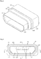
FIG. 1 is a perspective view illustrating a waterproof connection apparatus according to a first embodiment of this invention. -
FIG. 2 is a front view illustrating the waterproof connection apparatus according to the first embodiment. -
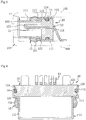
FIG. 3 is a sectional view taken along line A-A inFIG. 2 . -
FIG. 4 is a sectional view taken along line B-B inFIG. 2 . -
FIG. 5 is a perspective view illustrating a waterproof connection apparatus according to a second embodiment of this invention. -
FIG. 6 is a front view illustrating a waterproof connection apparatus according to the second embodiment. -
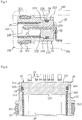
FIG. 7 is a sectional view taken along line C-C inFIG. 6 . -
FIG. 8 is a sectional view taken along line D-D inFIG. 6 . -
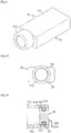
FIG. 9 is a perspective view illustrating a waterproof connection apparatus according to a third embodiment of this invention. -
FIG. 10 is a front view illustrating a waterproof connection apparatus according to the third embodiment. -
FIG. 11 is a longitudinal sectional view of a main part of the waterproof connection apparatus according to the third embodiment. -
FIG. 12 is a cross-sectional view of a main part of the waterproof connection apparatus according to the third embodiment. -
FIG. 13 is a sectional view corresponding to the view taken along line A-A, illustrating a first modification of the waterproof connection apparatus according to the first embodiment. -
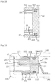
FIG. 14 is a sectional view corresponding to the view taken along line A-A, illustrating a second modification of the waterproof connection apparatus according to the first embodiment. - A
waterproof connection apparatus 10 for electronic equipment according to a first embodiment of the present invention is a waterproof connector which conforms to a standard such as the micro-USB standard and which is accommodated in electronic equipment such as mobile small-size electronic equipment such as, for example, multifunctional mobile phones, multifunctional mobile information terminals, mobile audio players, or electronic book readers. - As illustrated in
FIGS. 1 to 4 , thewaterproof connection apparatus 10 according to the first embodiment includes an approximately seamlesstubular shell 11, and theshell 11 corresponds to an approximately tubular outer case. A supportingportion 12 is accommodated in a wall form on the deep side of theshell 11, the supportingportion 12 supportscontact terminals 13 provided so as to pass through the supportingportion 12, and the front portions of thecontact terminals 13 are introduced into theshell 11. - The
shell 11 is seamless and theshell 11 is formed in an approximately square tubular form. A steppedportion 113 extending from afront portion 111 located close to an insertion side of a male-side connecting tool or a plug to arear portion 112 having a height and a width larger than those of thefront portion 111 is formed in a circumferential form on a circumferential surface so as to bulge outward. Theshell 11 is formed so that at least a region located closer to a front side than a front surface of the supportingportion 12 is formed as a non-perforated surface, and in this example, an entire region extending across thefront portion 111, the steppedportion 113, and therear portion 112 is formed as a non-perforated surface. - The supporting
portion 12 is formed of an insulating hard resin and is provided in a wall form so as to block the back side of theshell 11. The supportingportion 12 has an approximately rectangularparallelepiped body 121 having a recess at the center and is accommodated in and fitted to therear portion 112 of theshell 11 so that a partialfront surface 122 of thebody 121 abuts on the inner surface of the steppedportion 113. Moreover, acircumferential recess 124 made up of a groove and a notch is formed in a portion of an outercircumferential surface 123 of the supportingportion 12, and an O-ring 14 is fitted to therecess 124 so that the O-ring 14 is provided in the supportingportion 12. The O-ring 14 corresponds to a circumferential sealing portion and therecess 124 corresponds to a stepped portion at which the O-ring 14 can be fixed stationary. - The O-
ring 14 is formed of an elastic material such as rubber or a soft resin. The O-ring 14 is formed in a circumferential form and has an approximately circular cross-section. The O-ring 14 is provided so that a portion of the O-ring 14 protrudes outward from a portion of the outercircumferential surface 123 of the supportingportion 12 in a state before the supportingportion 12 is accommodated in theshell 11. Moreover, the supportingportion 12 is press-fitted to theshell 11 so as to crush the protruding portion of the O-ring 14. In the present embodiment, the O-ring 14 is pressure-contacted to the inner surface of theshell 11 in a circumferential form in a state in which the supportingportion 12 is press-fitted at a position at which thefront surface 122 abuts on the inner surface of the steppedportion 113. That is, the O-ring 14 corresponding to a circumferential sealing portion that seals the space between the supportingportion 12 and theshell 11 corresponding to the outer case is provided between theshell 11 and the supportingportion 12 at a position at which theshell 11 and the supportingportion 12 approach each other. - Furthermore, a plurality of
contact terminals 13 are partially buried in the supportingportion 12 by insert molding so as to pass through thebody 121. Thecontact terminals 13 are attached to the supportingportion 12 by insert molding so as to form a watertight structure. In the illustrated example, thecontact terminals 13 are arranged along one side of the protrudingportion 125 that protrudes from the front side of the supportingportion 12 and are introduced into theshell 11. Thecontact terminals 13 are exposed in theshell 11 so that thecontact terminals 13 can make conductive contact with plug-side terminals, and thecontact terminals 13 are pulled from the rear side of thebody 121 and are connected to a circuit board of the electronic equipment (not illustrated). An appropriate terminal of the plurality ofcontact terminals 13 can be configured as a power supply terminal and a ground terminal which is electrically connected to theshell 11. - Moreover, the sealing
member 15 is fitted to an outer circumference of theshell 11 at a position close to the rear side of thefront portion 111 so that one side surface thereof abuts on the steppedportion 113 in a circumferential form. The sealingmember 15 is formed of a soft resin such as elastomer in an approximately rectangular frame-shaped ring form and has a protrudingstrip 151 which has an approximately ridge-shaped cross-section and protrudes outward from a body having an approximately rectangular cross-section. The protrudingstrip 151 is pressure-contacted to thehousing 100 in a circumferential form by being pressed against ahousing body 101 and alid 102 that form thehousing 100 of the electronic equipment, for example, when thewaterproof connection apparatus 10 is accommodated in and attached to thehousing 100 of the electronic equipment whereby a watertight structure is formed (seeFIG. 3 ). InFIG. 3 , a connectingtool insertion opening 103 for a plug or the like is formed in a side wall of thehousing body 101. - The
waterproof connection apparatus 10 according to the first embodiment can be manufactured by an appropriate applicable method. According to a preferred manufacturing method, for example, a metal flat plate is subjected to drawing press processing to form themetallic shell 11 having a predetermined shape, thecontact terminals 13 are subjected to insert molding to form the supportingportion 12 having a predetermined shape by injection molding, and the O-ring 14 is fitted to therecess 124 of the supportingportion 12. - The supporting
portion 12 in which the O-ring 14 corresponding to the circumferential sealing portion is provided is inserted into theshell 11 corresponding to the outer case from therear portion 112 side. In this instance, the O-ring 14 protruding toward the outer circumference from a portion of the outercircumferential surface 123 of the supportingportion 12 is press-fitted to theshell 11 by sliding on the inner surface of theshell 11 so as to be crushed by the inner surface of theshell 11. - The supporting
portion 12 is inserted up to a position at which thefront surface 122 of the supportingportion 12 abuts on the inner surface of the steppedportion 113, the inserted O-ring 14 is pressure-contacted to the inner surface of theshell 11 in a circumferential form, and the O-ring 14 provided at a predetermined position between theshell 11 and the supportingportion 12 seals the space between theshell 11 and the supportingportion 12. After that, the sealingmember 15 is fitted to the outer circumference at a position close to the rear side of thefront portion 111 so that the side surface thereof abuts on the steppedportion 113 whereby thewaterproof connection apparatus 10 which is a waterproof connector is obtained. Alternatively, the supportingportion 12 may be press-fitted to theshell 11 in which the sealingmember 15 is fitted to the outer circumference thereof. - According to the
waterproof connection apparatus 10 according to the first embodiment, it is possible to seal the space between theshell 11 and the supportingportion 12 with the aid of the circumferential O-ring 14 to secure the waterproof performance between theshell 11 and the supportingportion 12. Therefore, it is not necessary to firmly fix the filling material to the inner surface of theshell 11 in the space on the deep side of theshell 11. Moreover, it is possible to prevent the filling material from peeling off the inner surface of theshell 11 by the intermittently applied force to form a gap to thereby deteriorate the waterproof performance. Moreover, since the O-ring 14 is disposed so as to be sandwiched between theshell 11 and the supportingportion 12, it is possible to reliably prevent water from entering from the space between theshell 11 and the supportingportion 12 accommodated therein into the deep side of theshell 11 with high durability. - Moreover, since a space for filling the filling material on the deep side of the
shell 11 is not necessary, it is possible to decrease the length of thewaterproof connection apparatus 10 to reduce the size thereof. Therefore, it is possible to decrease the area occupied by thewaterproof connection apparatus 10 to increase an available area inside the electronic equipment to thereby provide more freedom in the internal layout design of the electronic equipment and to achieve a reduction in the size of the electronic equipment. - Moreover, since the O-
ring 14 formed of an elastic material is pressure-contacted to the inner surface of theshell 11 in a circumferential form, even when force that partially or totally inflates theshell 11 is applied to theshell 11 and temporary or permanent deformation occurs in theshell 11, the elastic O-ring 14 can follow the inner surface of theshell 11 to maintain the waterproof performance. Furthermore, since the supportingportion 12 is press-fitted to theshell 11, it is possible to provide the supportingportion 12 at a predetermined position in theshell 11 with high stability. - Moreover, in a structure in which the O-
ring 14 protruding toward the outer circumference is press-fitted to theshell 11 and the supportingportion 12 and the O-ring 14 are provided in theshell 11, even when an error occurs in the positions of the O-ring 14 and the supportingportion 12 in theshell 11, it is possible to seal the space between theshell 11 and the supportingportion 12 to secure the waterproof performance and to provide a margin in the positional accuracy of the O-ring 14 and the supportingportion 12. Therefore, it is possible to alleviate assembling accuracy to reduce a manufacturing cost and to decrease the number of defective products to improve yield. - Moreover, when the sealing portion is provided on the entire outer
circumferential surface 123 of the supportingportion 12, frictional resistance when the supportingportion 12 is press-fitted to theshell 11 increases too much. In contrast, since the O-ring 14 is provided in a portion of the outercircumferential surface 123 of the supportingportion 12, it is possible to decrease the frictional resistance when the O-ring 14 is press-fitted to theshell 11 and to easily perform an assembling operation. - Moreover, due to the structure in which the O-
ring 14 as the sealing portion is fitted to the supportingportion 12, it is possible to provide waterproof and sealing properties to theshell 11 and the supportingportion 12 of various shapes and sizes at a low cost and to enhance versatility. Furthermore, when the outer case is themetallic shell 11, in a structure in which a resin filling material is provided in the space formed by the supportingportion 12 and the circumferential wall on the deep side of theshell 11, the resin filling material and the outer case easily peels off and the waterproof performance is more likely to deteriorate as compared to when the outer case is a resin case. In contrast, since the O-ring 14 is pressure-contacted to the inner surface of themetallic shell 11 in a circumferential form, it is possible to enhance waterproof stability and durability. - Similarly to the first embodiment, a
waterproof connection apparatus 20 for electronic equipment according to a second embodiment of the present invention is a waterproof connector which conforms to a standard such as the micro-USB standard and which is accommodated in electronic equipment such as mobile small-size electronic equipment such as, for example, multifunctional mobile phones, multifunctional mobile information terminals, mobile audio players, or electronic book readers. - As illustrated in
FIGS. 5 to 8 , thewaterproof connection apparatus 20 according to the second embodiment includes an approximatelytubular resin case 21, and thecase 21 corresponds to an approximately tubular outer case. A supportingportion 22 is accommodated in a wall form on the deep side of thecase 21, the supportingportion 22 supportscontact terminals 23 provided so as to pass through the supportingportion 22, and the front portions of thecontact terminals 23 are introduced into thecase 21. Moreover, ametallic shell 26 is attached on the inner side of thecase 21, located closer to a front side than a portion which is blocked by the supportingportion 22, and the front portions of thecontact terminals 23 are arranged on the inner side of theshell 26. - The
case 21 has an approximately rectangular tubular form and is formed of a hard resin such as a polycarbonate resin or an ABS resin. A recessedgroove 211 is formed along an outer circumferential surface located close to the front side of thecase 21, and a sealingmember 25 to be described later is provided in a state of being fitted to the recessedgroove 211. A steppedportion 213 is formed on the inner side close to therear portion 212 of thecase 21, and the space on the inner side of therear portion 212 of thecase 21 has a height and a width larger than that of the space on the inner side of a portion located closer to the front side. - The supporting
portion 22 is formed of an insulating hard resin and is provided in a wall form so as to block the deep side of thecase 21. The supportingportion 22 has an approximately rectangularparallelepiped body 221, an approximately rectangular columnar steppedportion 222 is formed near the front end of thebody 221 so that a central region thereof protrudes forward, and the steppedportion 222 is fitted to the front portion of thecase 21. - The supporting
portion 22 is accommodated in and fitted to therear portion 212 of thecase 21 so that afront surface 223 located closer to the outer circumference than the steppedportion 222 abuts on the inner surface of the steppedportion 213 of thecase 21. Moreover, acircumferential recess 225 configured as a groove is formed in a portion of an outercircumferential surface 224 of the supportingportion 22, and the O-ring 24 is fitted to therecess 225 so that the O-ring 24 is provided in the supportingportion 22. The O-ring 24 corresponds to a circumferential sealing portion, and therecess 225 corresponds to a stepped portion at which the O-ring 24 can be fixed stationary. - The O-
ring 24 is formed of an elastic material such as rubber or a soft resin. The O-ring 24 is formed in a circumferential form and has an approximately circular cross-section. The O-ring 24 is provided so that a portion of the O-ring 24 protrudes outward from a portion of the outercircumferential surface 224 of the supportingportion 22 in a state before the supportingportion 22 is accommodated in thecase 21. Moreover, the supportingportion 22 is press-fitted to thecase 21 so as to crush the protruding portion of the O-ring 24. In the present embodiment, the O-ring 24 is pressure-contacted to the inner surface of thecase 21 in a circumferential form in a state in which the supportingportion 22 is press-fitted at a position at which thefront surface 223 abuts on the inner surface of the steppedportion 213. That is, the O-ring 24 corresponding to a circumferential sealing portion that seals the space between the supportingportion 22 and thecase 21 corresponding to the outer case is provided between thecase 21 and the supportingportion 22 at a position at which thecase 21 and the supportingportion 22 approach each other. - Furthermore, similarly to the first embodiment, a plurality of
contact terminals 23 is partially buried in the supportingportion 22 by insert molding so as to pass through thebody 221. Thecontact terminals 23 are attached to the supportingportion 22 so as to form a watertight structure by insert molding. In the illustrated example, thecontact terminals 23 are arranged along one side of the protrudingportion 226 that protrudes from the front side of the supportingportion 22 and are introduced into thecase 21 and theshell 26. Thecontact terminals 23 are exposed in thecase 21 and theshell 26 so that thecontact terminals 23 can make conductive contact with terminals close to a plug or the like, and thecontact terminals 23 are pulled from the rear side of thebody 221 and are connected to a circuit board of the electronic equipment (not illustrated). An appropriate terminal of the plurality ofcontact terminals 23 can be configured as a power supply terminal and a ground terminal which is electrically connected to theshell 26. - Moreover, the sealing
member 25 fitted to an outer circumference of thecase 21 is formed of a soft resin such as elastomer in an approximately rectangular frame-shaped ring form and has a protrudingstrip 251 which has an approximately ridge-shaped cross-section and protrudes outward from a body having an approximately rectangular cross-section. The protrudingstrip 251 is pressure-contacted to thehousing 100 in a circumferential form by being pressed against ahousing body 101 having a connectingtool insertion opening 103 for a plug or the like and alid 102 that form thehousing 100 of the electronic equipment, for example, when thewaterproof connection apparatus 20 is accommodated in and attached to thehousing 100 of the electronic equipment whereby a watertight structure is formed (seeFIG. 7 ). - The
waterproof connection apparatus 20 according to the second embodiment can be manufactured by an appropriate applicable method. According to a preferred manufacturing method, for example, thecase 21 having a predetermined shape is formed by injection molding, thecontact terminals 23 are subjected to insert molding to form the supportingportion 22 having a predetermined shape by injection molding, and the O-ring 24 is fitted to therecess 225 of the supportingportion 22. - The supporting
portion 22 in which the O-ring 24 corresponding to the circumferential sealing portion is provided is inserted into thecase 21 corresponding to the outer case from therear portion 212 side. In this instance, the O-ring 24 protruding toward the outer circumference from a portion of the outercircumferential surface 224 of the supportingportion 22 is press-fitted to thecase 21 by sliding on the inner surface of thecase 21 so as to be crushed by the inner surface of thecase 21. In this example, a portion of thecase 21 close to the rear end of therear portion 212 is preferably formed in such a tapered form as to spread toward the rear end so that the supportingportion 22 is inserted easily. - The supporting
portion 22 is inserted up to a position at which thefront surface 223 of the supportingportion 22 abuts on the inner surface of the steppedportion 213 of thecase 21, the inserted O-ring 24 is pressure-contacted to the inner surface of thecase 21 in a circumferential form, and the O-ring 24 provided at a predetermined position between thecase 21 and the supportingportion 22 seals the space between thecase 21 and the supportingportion 22. - After that, the
shell 26 is inserted from the front side so as to be accommodated in thecase 21 so that a portion of theshell 26 near the rear end is fitted between the inner surface of thecase 21 and the side surface of the steppedportion 222 of the supportingportion 22, and the sealingmember 25 is fitted to the recessedgroove 211 of thecase 21 whereby thewaterproof connection apparatus 20 which is the waterproof connector is obtained. Alternatively, the supportingportion 22 may be press-fitted from therear portion 212 side in a state in which theshell 26 is accommodated in thecase 21 to create a state in which a portion of theshell 26 close to the rear end is fitted between the inner surface of thecase 21 and the side surface of the steppedportion 222 of the supportingportion 22. Still alternatively, press-fitting of the supportingportion 22, insertion of theshell 26, or both may be performed in a state in which the sealingmember 25 is attached to thecase 21. - According to the
waterproof connection apparatus 20 according to the second embodiment, it is possible to seal the space between thecase 21 and the supportingportion 22 with the aid of the circumferential O-ring 24 to secure the waterproof performance between thecase 21 and the supportingportion 22. Therefore, it is not necessary to firmly fix the filling material to the inner surface of thecase 21 in the space on the deep side of thecase 21. Moreover, it is possible to prevent the filling material from peeling off the inner surface of thecase 21 by the intermittently applied force to form a gap to thereby deteriorate the waterproof performance. Furthermore, since the O-ring 24 is disposed so as to be sandwiched between thecase 21 and the supportingportion 22, it is possible to reliably prevent water from entering from the space between thecase 21 and the supportingportion 22 accommodated therein into the deep side of thecase 21 with high durability. - Moreover, since a space for filling the filling material on the deep side of the
case 21 is not necessary, it is possible to decrease the length of thewaterproof connection apparatus 20 to reduce the size thereof. Therefore, it is possible to decrease the area occupied by thewaterproof connection apparatus 20 to increase an available area inside the electronic equipment to thereby provide more freedom in the internal layout design of the electronic equipment and to achieve a reduction in the size of the electronic equipment. - Moreover, since the O-
ring 24 formed of an elastic material is pressure-contacted to the inner surface of thecase 21 in a circumferential form, even when force that partially or totally inflates thecase 21 is applied to thecase 21 and temporary or permanent deformation occurs in thecase 21, the elastic O-ring 24 can follow the inner surface of thecase 21 to maintain the waterproof performance. Furthermore, since the supportingportion 22 is press-fitted to thecase 21, it is possible to provide the supportingportion 22 at a predetermined position in thecase 21 with high stability. - Moreover, similarly to the first embodiment, even when an error occurs in the positions of the O-
ring 24 and the supportingportion 22 in thecase 21, since it is possible to secure the waterproof performance and to provide a margin in the positional accuracy of the O-ring 24 and the supportingportion 22, it is possible to alleviate assembling accuracy to reduce a manufacturing cost and to decrease the number of defective products to improve yield. Furthermore, since the O-ring 24 is provided in a portion of the outercircumferential surface 224 of the supportingportion 22, it is possible to decrease the frictional resistance when the O-ring 24 is press-fitted to thecase 21 and to easily perform an assembling operation. - A
waterproof connection apparatus 30 for electronic equipment according to a third embodiment of the present invention is a multipolar waterproof jack such as an earphone jack, which is accommodated in electronic equipment such as mobile small-size electronic equipment such as, for example, multifunctional mobile phones, multifunctional mobile information terminals, or mobile audio players. - As illustrated in
FIGS. 9 to 12 , thewaterproof connection apparatus 30 according to the third embodiment includes an approximatelytubular resin housing 31, and thehousing 31 corresponds to an approximately tubular outer case. A supportingportion 32 is accommodated in a wall form on the deep side of thehousing 31, the supportingportion 32 supportscontact terminals 33 provided so as to pass through the supportingportion 32, and the front portions of thecontact terminals 33 are introduced into thehousing 31. - The
housing 31 is formed of a hard resin such as a polycarbonate resin or an AB S resin. Abody 311 of thehousing 31 has an approximately rectangular tubular form, and afront portion 312 on a plug insertion side has an approximately cylindrical form. A steppedsurface 314 on which the supportingportion 32 abuts is formed on an inner surface of therear portion 313 of thebody 311. - The supporting
portion 32 is formed of an insulating hard resin in an approximately rectangular parallelepiped form and is provided in a wall form so as to block the deep side of thehousing 31. The supportingportion 32 is accommodated in and fitted to arear portion 313 of thehousing 31 so that a portion of the supportingportion 32 close to a peripheral edge of afront surface 321 abuts on the steppedsurface 314 of thehousing 31. - A
circumferential recess 323 configured as a groove is formed in a portion of an outercircumferential surface 322 of the supportingportion 32, and an O-ring 34 is fitted to therecess 323 so that the O-ring 34 is provided in the supportingportion 32. The O-ring 34 corresponds to a circumferential sealing portion, and therecess 323 corresponds to a stepped portion at which the O-ring 34 can be fixed stationary. - The O-
ring 34 is formed of an elastic material such as rubber or a soft resin. The O-ring 34 is formed in a circumferential form and has an approximately circular cross-section. The O-ring 34 is provided so that a portion of the O-ring 34 protrudes from a portion of the outercircumferential surface 322 of the supportingportion 32 toward the outer circumference in a state before the supportingportion 32 is accommodated in thehousing 31. Moreover, the supportingportion 32 is press-fitted to thehousing 31 so as to crush the protruding portion of the O-ring 34. In the present embodiment, the O-ring 34 is pressure-contacted to the inner surface of thehousing 31 in a circumferential form in a state in which the supportingportion 32 is press-fitted at a position at which thefront surface 321 abuts on the steppedportion 314. That is, the O-ring 34 corresponding to a circumferential sealing portion that seals the space between the supportingportion 32 and thehousing 31 corresponding to the outer case is provided between thehousing 31 and the supportingportion 32 at a position at which thehousing 31 and the supportingportion 32 approach each other. - Moreover, in the present embodiment, the
contact terminal 33 supported by the supportingportion 32 includes a contacting terminal portion 331 having a plate spring form, which makes contact with a plug-side terminal at a contact point at the distal end thereof and anextension terminal portion 332 provided so as to pass through the supportingportion 32 and supported by the supportingportion 32. The respective contacting terminal portions 331 are accommodated in thehousing 31 so that a portion thereof is fitted to an attachment groove (not illustrated) formed in thehousing 31. The respectiveextension terminal portions 332 are partially buried in the supportingportion 32 by insert molding and are attached to the supportingportion 32 by insert molding so as to form a watertight structure. - In a state in which the supporting
portion 32 is press-fitted at a predetermined position in thehousing 31, the respectiveextension terminal portions 332 partially exposed on the front side of the supportingportion 32 and the corresponding contacting terminal portions 331 accommodated in thehousing 31 are electrically connected to form therespective contact terminals 33. A structure that electrically connects theextension terminal portion 332 and the contacting terminal portion 331 can be realized by, for example, a configuration in which an insertion hole to which the distal end of theextension terminal portion 332 is exposed is formed on the inner side of the front surface of the supportingportion 32, the supportingportion 32 is press-fitted so that the rear end of the contacting terminal portion 331 is inserted into the insertion hole, and theextension terminal portion 332 and the contacting terminal portion 331 are pressure-contacted and connected so that the distal end of theextension terminal portion 332 and the rear end of the contacting terminal portion 331 are sandwiched at the insertion hole. Alternatively, the structure can be realized by a configuration in which any one of the distal end of theextension terminal portion 332 and the rear end of the contacting terminal portion 331 is configured as a plate spring so as to be connected to the other end in an elastically contacting manner. - The
respective contact terminals 33 can be formed integrally by insert-molding the rear portions thereof to the supportingportion 32 so as to pass through the supportingportion 32. In this instance, thecontact terminals 33 are accommodated in thehousing 31 so that thecontact terminals 33 are inserted in the attachment groove of thehousing 31 when the supportingportion 32 is press-fitted. - Moreover, the
contact terminals 33 are provided to be exposed in thehousing 31 so that thecontact terminals 33 can make contact with the plug-side terminals at the contact points at the distal end. Thecontact terminals 33 are pulled from the rear side of the supportingportion 32 and are connected to a circuit board of the electronic equipment (not illustrated). Thewaterproof connection apparatus 30 which is a waterproof jack configured in this manner is accommodated in and attached to thehousing 100 of the electronic equipment similarly to the first and second embodiments. - The
waterproof connection apparatus 30 according to the third embodiment can be manufactured by an appropriate applicable method. According to a preferred manufacturing method, for example, thehousing 31 having a predetermined shape is formed by injection molding, thecontact terminals 33 or theextension terminal portions 332 of thecontact terminals 33 are subjected to insert molding to form the supportingportion 32 having a predetermined shape by injection molding, and the O-ring 34 is fitted to therecess 323 of the supportingportion 32. - The supporting
portion 32 in which the O-ring 34 corresponding to the circumferential sealing portion is provided is inserted into thehousing 31 corresponding to the outer case from therear portion 313 side. In this instance, the O-ring 34 protruding toward the outer circumference from a portion of the outercircumferential surface 322 of the supportingportion 32 is press-fitted to thehousing 31 by sliding on the inner surface of thehousing 31 so as to be crushed by the inner surface of thehousing 31. - The supporting
portion 32 is inserted up to a position at which thefront surface 321 of the supportingportion 32 abuts on the steppedsurface 314 of thehousing 31, the inserted O-ring 34 is pressure-contacted to the inner surface of thehousing 31 in a circumferential form, and the O-ring 34 provided at a predetermined position between thehousing 31 and the supportingportion 32 seals the space between thehousing 31 and the supportingportion 32. In this way, thewaterproof connection apparatus 30 which is a multipolar waterproof jack is obtained. - When the
extension terminal portions 332 of thecontact terminals 33 are insert-molded to the supportingportion 32, before the supportingportion 32 is inserted, the contacting terminal portions 331 are accommodated in thehousing 31, and then, the supportingportion 32 is inserted. In a stage where the supportingportion 32 is inserted up to a predetermined position, the contacting terminal portions 331 and theextension terminal portions 332 insert-molded to the supportingportion 32 are pressure-contacted and electrically connected. Moreover, similarly to the first and second embodiments, a portion of thehousing 31 close to the rear end may be formed in such a tapered form as to spread toward the rear end so that the supportingportion 32 is inserted easily. - According to the
waterproof connection apparatus 30 according to the third embodiment, it is possible to seal the space between thehousing 31 and the supportingportion 32 with the aid of the circumferential O-ring 34 to secure the waterproof performance between thehousing 31 and the supportingportion 32. Therefore, it is not necessary to firmly fix the filling material to the inner surface of thehousing 31 in the space on the deep side of thehousing 31. Moreover, it is possible to prevent the filling material from peeling off the inner surface of thehousing 31 by the intermittently applied force to form a gap to thereby deteriorate the waterproof performance. Furthermore, since the O-ring 34 is disposed so as to be sandwiched between thehousing 31 and the supportingportion 32, it is possible to reliably prevent water from entering from the space between thehousing 31 and the supportingportion 32 accommodated therein into the deep side of thehousing 31 with high durability. - Moreover, since a space for filling the filling material on the deep side of the
housing 31 is not necessary, it is possible to decrease the length of thewaterproof connection apparatus 30 to reduce the size thereof. Therefore, it is possible to decrease the area occupied by thewaterproof connection apparatus 30 to increase an available area inside the electronic equipment to thereby provide more freedom in the internal layout design of the electronic equipment and to achieve a reduction in the size of the electronic equipment. - Moreover, since the O-
ring 34 formed of an elastic material is pressure-contacted to the inner surface of thehousing 31 in a circumferential form, even when force that partially or totally inflates thehousing 31 is applied to thehousing 31 and temporary or permanent deformation occurs in thehousing 31, the elastic O-ring 34 can follow the inner surface of thehousing 31 to maintain the waterproof performance. Furthermore, since the supportingportion 32 is press-fitted to thehousing 31, it is possible to provide the supportingportion 32 at a predetermined position in thehousing 31 with high stability. - Moreover, similarly to the first and second embodiments, even when an error occurs in the positions of the O-
ring 34 and the supportingportion 32 in thehousing 31, since it is possible to secure the waterproof performance and to provide a margin in the positional accuracy of the O-ring 34 and the supportingportion 32, it is possible to alleviate assembling accuracy to reduce a manufacturing cost and to decrease the number of defective products to improve yield. Furthermore, since the O-ring 34 is provided in a portion of the outercircumferential surface 322 of the supportingportion 32, it is possible to decrease the frictional resistance when the O-ring 34 is press-fitted to thehousing 31 and to easily perform an assembling operation. - The invention disclosed in this specification includes, in addition to the structures according to respective inventions or embodiments, in an applicable range, a matter defined by modifying any of these partial configurations into other configurations disclosed in this specification, a matter defined by adding any other configurations disclosed in this specification to these partial configurations, or a matter defined into a generic concept by cancelling any of these partial configurations within a limit that achieves a partial operational advantage. The invention disclosed in this specification further includes the following modifications.
- For example, in the first to third embodiments, although the O-
ring waterproof connection apparatus 10a according to a modification of the first embodiment is illustrated inFIG. 13 . - In the
waterproof connection apparatus 10a illustrated inFIG. 13 , an elasticresin sealing portion 16a formed of an elastic resin is provided in a portion corresponding to therecess 124 of a supportingportion 12a instead of a configuration in which therecess 124 is formed in the supportingportion 12 and the O-ring 14 is fitted to therecess 124. The elasticresin sealing portion 16a is integrally fixed to the supportingportion 12a formed of a hard resin and has a protruding portion that protrudes toward the outer circumference from the outercircumferential surface 123 of the supportingportion 12a. In a state in which the supportingportion 12a is press-fitted to theshell 11, the protruding portion of the elasticresin sealing portion 16a is press-fitted by theshell 11, whereby the elasticresin sealing portion 16a is pressure-contacted to the inner surface of theshell 11 in a circumferential form. The other configurations are the same as those of the first embodiment. In this example, it is possible to completely prevent water from entering from the space between the elasticresin sealing portion 16a and the supportingportion 12a and to further enhance the sealing-based waterproof performance. The same modification can be appropriately applied to the second and third embodiments. - Moreover, a configuration in which the circumferential sealing portion is provided is not limited to a configuration in which the sealing portion is provided so as to protrude outward from the outer circumferential surface of the supporting portion. For example, a configuration in which the sealing portion is provided so as to protrude toward the front surface of the supporting portion or a configuration in which the circumferential sealing portion is provided so as to protrude toward both the front surface of the supporting portion and the outer circumference may be used. As a preferred modification, a
waterproof connection apparatus 10b according to a modification of the first embodiment is illustrated inFIG. 14 . - In the
waterproof connection apparatus 10b illustrated inFIG. 14 , a waterproof double-sided tape 17b as the circumferential sealing portion is provided on thefront surface 122 of the supportingportion 12b instead of a configuration in which therecess 124 is formed on the outer circumferential side of the supportingportion 12 and the O-ring 14 is fitted to therecess 124. The waterproof double-sided tape 17b has one surface bonded to thefront surface 122 of the supportingportion 12b in a circumferential form and the other surface bonded to the inner surface of the stepped portion 115 of theshell 11 corresponding to the outer case. This structure is formed by inserting the supportingportion 12b in which the waterproof double-sided tape 17b having the front surface configured as a bonding surface is provided on the front surface side into theshell 11 and bonding the front surface of the waterproof double-sided tape 17b to the inner surface of the stepped portion 115 of theshell 11 by bringing the front surface into contact with the inner surface. The other configurations are basically the same as those of the first embodiment. - In this example, since the waterproof double-
sided tape 17b on the front surface side of the supportingportion 12b is inserted until the waterproof double-sided tape 17b abuts on the stepped portion 115 and is bonded to the stepped portion 115, it is possible to arrange the supportingportion 12b and the waterproof double-sided tape 17b at an accurate position in theshell 11 to realize waterproof and sealing properties. Therefore, it is possible to enhance the uniformity of products. Furthermore, since the waterproof double-sided tape 17b is used, it is possible to provide waterproof and sealing properties to the supportingportion 12b and theshell 11 of various shapes and sizes at a low cost and to enhance versatility. A circumferential sealing portion provided on a front surface side of the supportingportion 12b that can be bonded to theshell 11 is appropriate. For example, a configuration in which an elastic resin sealing portion integrated with the supportingportion 12b is provided so as to protrude toward the front surface side of the supportingportion 12b and has a front surface configured as a bonding surface so as to be bonded to the inner surface of the stepped portion 115 of theshell 11 may be used. Moreover, an appropriate surface positioned to face the front side of the supporting portion is included on the front surface side of the supporting portion in which the sealing portion is provided. Thefront surface 122 of the supportingportion 12b is included, and an inclined surface formed at a corner portion of the supporting portion and disposed on the front surface side of the supporting portion (for example, an inclined surface inclined so as to spread toward the rear side from a portion near the outer circumference of the front surface 122) is included. Furthermore, the same modification in which the circumferential sealing portion is provided on the front surface side of the supporting portion can be appropriately applied to the second and third embodiments. - Moreover, a circumferential sealing portion may be provided in advance on the outer case and the supporting portion may be inserted into the outer case so that the supporting portion is pressure-contacted or bonded to the circumferential sealing portion. For example, a circumferential O-ring may be fitted to a corner portion made up of the
rear portion 113 and the stepped portion 115 of theshell 11, a supporting portion having a circumferential recess configured as a notch formed in a circumferential edge of the front surface thereof may be inserted into theshell 11, and the O-ring may be pressure-contacted to the inner surface of therear portion 113 of theshell 11 in a protruding portion on the inner side of the recess so that the O-ring is fitted to the circumferential recess which is a notch having an L-shaped cross-section. Alternatively, a waterproof double-sided tape may be bonded to the inner surface of the stepped portion 115 of theshell 11 in a circumferential form, and in this state, the supporting portion is inserted into theshell 11 so that the front surface of the supporting portion is bonded to the waterproof double-sided tape in a circumferential form. - The present invention is applicable as a waterproof connector used for electrical connection of various types of electronic equipment such as, for example, multifunctional mobile phones, multifunctional mobile information terminals, mobile audio players, or electronic book readers.
-
- 10, 10a, 10b:
- Waterproof connection apparatus
- 11:
- Shell
- 111:
- Front portion
- 112:
- Rear portion
- 113:
- Stepped portion
- 12, 12a, 12b:
- Supporting portion
- 121:
- Body
- 122:
- Front surface
- 123:
- Outer circumferential surface
- 124:
- Recess
- 125:
- Protruding portion
- 13:
- Contact terminal
- 14:
- O-ring
- 15:
- Sealing member
- 151:
- Protruding strip
- 16a:
- Elastic resin sealing portion
- 17b:
- Waterproof double-sided tape
- 20:
- Waterproof connection apparatus
- 21:
- Case
- 211:
- Recessed groove
- 212:
- Rear portion
- 213:
- Stepped portion
- 22:
- Supporting portion
- 221:
- Body
- 222:
- Stepped portion
- 223:
- Front surface
- 224:
- Outer circumferential surface
- 225:
- Recess
- 226:
- Protruding portion
- 23:
- Contact terminal
- 24:
- O-ring
- 25:
- Sealing member
- 251:
- Protruding strip
- 26:
- Shell
- 30:
- Waterproof connection apparatus
- 31:
- Housing
- 311:
- Body
- 312:
- Front portion
- 313:
- Rear portion
- 314:
- Stepped surface
- 32:
- Supporting portion
- 321:
- Front surface
- 322:
- Outer circumferential surface
- 323:
- Recess
- 33:
- Contact terminal
- 331:
- Contacting terminal portion
- 332:
- Extension terminal portion
- 34:
- O-ring
- 100:
- Housing of electronic equipment
- 101:
- Housing body
- 102:
- Lid
- 103:
- Connecting tool insertion opening
Claims (8)
- A waterproof connection apparatus for electronic equipment, comprising:an approximately tubular outer case (11);a supporting portion (12) accommodated in a wall form on a deep side of the outer case (11);a contact terminal (13) supported by the supporting portion (12) and introduced in the outer case (11); anda circumferential sealing portion (14) provided between the outer case (11) and the supporting portion (12) at a position at which the outer case (11) and the supporting portion (12) approach each other so as to seal a space between the outer case (11) and the supporting portion (12);characterized in thatthe approximately tubular outer case (11) comprises a seamless shell (11) formed by drawing press processing on a metal flat plate.
- The waterproof connection apparatus for electronic equipment according to claim 1, wherein
the sealing portion (14) is formed of an elastic material and is provided in the supporting portion (12), and
the sealing portion (14) is pressure-contacted to an inner surface of the outer case (11) in a circumferential form so that the supporting portion (12) is press-fitted to the outer case (11). - The waterproof connection apparatus for electronic equipment according to claim 2, wherein
the sealing portion (14) is provided in a state of press-fitting a protruding portion that protrudes outward from a portion of an outer circumferential surface (123) of the supporting portion (12). - The waterproof connection apparatus for electronic equipment according to claim 2 or 3, wherein
the sealing portion (14) is an O-ring (14) and the O-ring (14) is fitted to a stepped portion (113) of the supporting portion (12) at which the O-ring (14) can be fixed stationary. - The waterproof connection apparatus for electronic equipment according to claim 2 or 3, wherein
the sealing portion is formed of an elastic resin that is integrated with the supporting portion (12b). - The waterproof connection apparatus for electronic equipment according to claim 1, wherein
the sealing portion is provided on a front surface side of the supporting portion (12b) and is bonded to a stepped portion (115) of the outer case (11) in a circumferential form. - The waterproof connection apparatus for electronic equipment according to claim 6, wherein
the sealing portion is a waterproof double-sided tape (17b) having one surface bonded to the front surface side (122) of the supporting portion (12b) and the other surface bonded to the stepped portion (115) of the outer case (11). - Electronic equipment comprising the waterproof connection apparatus for electronic equipment according to any one of claims 1 to 7 accommodated in a housing.
Applications Claiming Priority (3)
| Application Number | Priority Date | Filing Date | Title |
|---|---|---|---|
| JP2014108087A JP2015225712A (en) | 2014-05-26 | 2014-05-26 | Waterproof connector of electronic apparatus and electronic apparatus |
| EP15800158.6A EP3151346A4 (en) | 2014-05-26 | 2015-05-11 | Waterproof connection apparatus for electronic equipment, and electronic equipment |
| PCT/JP2015/002380 WO2015182049A1 (en) | 2014-05-26 | 2015-05-11 | Waterproof connection apparatus for electronic equipment, and electronic equipment |
Related Parent Applications (1)
| Application Number | Title | Priority Date | Filing Date |
|---|---|---|---|
| EP15800158.6A Division EP3151346A4 (en) | 2014-05-26 | 2015-05-11 | Waterproof connection apparatus for electronic equipment, and electronic equipment |
Publications (2)
| Publication Number | Publication Date |
|---|---|
| EP3561965A1 EP3561965A1 (en) | 2019-10-30 |
| EP3561965B1 true EP3561965B1 (en) | 2020-10-28 |
Family
ID=54698408
Family Applications (2)
| Application Number | Title | Priority Date | Filing Date |
|---|---|---|---|
| EP19181015.9A Active EP3561965B1 (en) | 2014-05-26 | 2015-05-11 | Waterproof connection apparatus for electronic equipment, and electronic equipment |
| EP15800158.6A Withdrawn EP3151346A4 (en) | 2014-05-26 | 2015-05-11 | Waterproof connection apparatus for electronic equipment, and electronic equipment |
Family Applications After (1)
| Application Number | Title | Priority Date | Filing Date |
|---|---|---|---|
| EP15800158.6A Withdrawn EP3151346A4 (en) | 2014-05-26 | 2015-05-11 | Waterproof connection apparatus for electronic equipment, and electronic equipment |
Country Status (6)
| Country | Link |
|---|---|
| US (1) | US10027052B2 (en) |
| EP (2) | EP3561965B1 (en) |
| JP (1) | JP2015225712A (en) |
| KR (1) | KR101851997B1 (en) |
| CN (1) | CN106415943A (en) |
| WO (1) | WO2015182049A1 (en) |
Families Citing this family (22)
| Publication number | Priority date | Publication date | Assignee | Title |
|---|---|---|---|---|
| US10826255B2 (en) * | 2013-07-19 | 2020-11-03 | Foxconn Interconnect Technology Limited | Flippable electrical connector |
| JP5925865B1 (en) * | 2014-11-14 | 2016-05-25 | 日本航空電子工業株式会社 | Waterproof connector |
| CN107534694A (en) * | 2016-03-29 | 2018-01-02 | 华为技术有限公司 | A kind of mobile terminal port and mobile terminal |
| JP2017208193A (en) * | 2016-05-17 | 2017-11-24 | 日本圧着端子製造株式会社 | Waterproof connector |
| CN108232699B (en) * | 2016-12-15 | 2020-10-30 | 富士康(昆山)电脑接插件有限公司 | Electrical connector |
| CN107026359B (en) * | 2017-02-27 | 2019-02-22 | Oppo广东移动通信有限公司 | Waterproof jacket, attachment device and mobile terminal |
| JP6230013B1 (en) * | 2017-04-07 | 2017-11-15 | Smk株式会社 | Electrical connector |
| TWI635667B (en) * | 2017-08-08 | 2018-09-11 | 祥峰實業股份有限公司 | High-speed signal transmission connector with high water resistance |
| KR101951677B1 (en) * | 2017-08-22 | 2019-02-25 | 엘지전자 주식회사 | Connector water proof housing and mobile terminal |
| CN109428190B (en) * | 2017-08-25 | 2021-10-26 | 富士康(昆山)电脑接插件有限公司 | Electric connector combination and manufacturing method thereof |
| KR101947952B1 (en) | 2018-04-02 | 2019-02-13 | 고영상 | Portable communication device having a functionmodule |
| DE112019002049T5 (en) * | 2018-05-17 | 2020-12-31 | Hitachi Automotive Systems, Ltd. | Electronic control device |
| JP6624241B2 (en) * | 2018-06-13 | 2019-12-25 | 富士電機機器制御株式会社 | Wiring connection equipment, electrical equipment and circuit breakers |
| US11101595B2 (en) * | 2018-06-27 | 2021-08-24 | Lg Electronics Inc. | Mobile terminal |
| US10276972B1 (en) * | 2018-08-14 | 2019-04-30 | Avertronics, Inc. | Power connector |
| CN111009777B (en) * | 2018-10-08 | 2023-01-24 | 富顶精密组件(深圳)有限公司 | Electric connector and manufacturing method thereof |
| JP6953485B2 (en) * | 2019-08-30 | 2021-10-27 | 矢崎総業株式会社 | Waterproof seal structure of connector |
| DE102020204913A1 (en) * | 2020-04-17 | 2021-10-21 | Te Connectivity Germany Gmbh | Miniaturized connector |
| TWI759038B (en) * | 2020-12-28 | 2022-03-21 | 唐虞企業股份有限公司 | Connector assembly and its connector |
| CN116848738A (en) * | 2021-01-12 | 2023-10-03 | 科利耳有限公司 | Electrical connector having multiple seals to inhibit liquid ingress |
| US11682856B2 (en) * | 2021-01-19 | 2023-06-20 | Bittium Biosignals Oy | Holder apparatus of bio-signal device and method of assembling holder apparatus |
| CN113613446B (en) * | 2021-07-01 | 2022-09-23 | 荣耀终端有限公司 | Terminal device |
Family Cites Families (37)
| Publication number | Priority date | Publication date | Assignee | Title |
|---|---|---|---|---|
| US4976634A (en) * | 1989-08-31 | 1990-12-11 | Amp Incorporated | Means and method of securing an insert in a shell |
| DE4019570A1 (en) | 1990-06-20 | 1992-01-02 | Volkswagen Ag | ELECTRICAL DEVICE, ESPECIALLY SWITCHING AND CONTROL UNIT FOR MOTOR VEHICLES |
| JP3097367B2 (en) | 1991-12-25 | 2000-10-10 | 住友電装株式会社 | Waterproof shield connector |
| JP2881430B2 (en) * | 1993-12-24 | 1999-04-12 | 山一電機 株式会社 | Shield connector assembly |
| JP3753363B2 (en) * | 2000-02-29 | 2006-03-08 | 矢崎総業株式会社 | connector |
| JP2002134219A (en) * | 2000-10-30 | 2002-05-10 | Yazaki Corp | Water-proofing connector and manufacturing method of the water-proofing connector |
| JP3966407B2 (en) * | 2002-09-24 | 2007-08-29 | 矢崎総業株式会社 | Electromagnetic wave shield structure with oil-proof water |
| TW549710U (en) * | 2002-11-15 | 2003-08-21 | Hon Hai Prec Ind Co Ltd | Cable end connector assembly |
| JP2005019188A (en) * | 2003-06-26 | 2005-01-20 | Auto Network Gijutsu Kenkyusho:Kk | Connector for apparatus |
| JP4220880B2 (en) * | 2003-10-17 | 2009-02-04 | 住友重機械工業株式会社 | Waterproof terminal block unit |
| CN2773936Y (en) * | 2004-12-30 | 2006-04-19 | 富士康(昆山)电脑接插件有限公司 | Electric connector |
| JP4713380B2 (en) * | 2006-03-24 | 2011-06-29 | タイコエレクトロニクスジャパン合同会社 | Waterproof squib connector |
| KR101315475B1 (en) * | 2007-06-04 | 2013-10-04 | 타이코에이엠피(유) | a connecting module of mobile commnication terminal |
| CN101919124B (en) * | 2008-01-15 | 2013-03-27 | 株式会社藤仓 | Waterproof connector for flexible substrate |
| US8025530B2 (en) * | 2008-07-14 | 2011-09-27 | Savi Technology, Inc. | Method and apparatus involving a housing with a sealed electrical connector |
| JP5528007B2 (en) * | 2009-05-13 | 2014-06-25 | 矢崎総業株式会社 | Shielded wire fixing structure and fixing method |
| JP4880018B2 (en) | 2009-09-28 | 2012-02-22 | ソニー・エリクソン・モバイルコミュニケーションズ株式会社 | Portable terminal device and case waterproof structure |
| US8092252B2 (en) * | 2010-05-31 | 2012-01-10 | Cheng Uei Precision Industry Co., Ltd. | Electrical connector |
| JP2012009358A (en) * | 2010-06-25 | 2012-01-12 | Jst Mfg Co Ltd | Shield case for connector and electrical connector |
| JP2012009357A (en) | 2010-06-25 | 2012-01-12 | Jst Mfg Co Ltd | Electrical connector |
| US7922535B1 (en) * | 2010-11-05 | 2011-04-12 | Cheng Uei Precision Industry Co., Ltd. | Electrical connector |
| JP5673457B2 (en) * | 2011-01-19 | 2015-02-18 | 日立金属株式会社 | connector |
| JP5758640B2 (en) * | 2011-02-04 | 2015-08-05 | 株式会社フロウエル | Tube fitting |
| JP5689000B2 (en) | 2011-03-16 | 2015-03-25 | 株式会社エクセル電子 | Electronic device connector, electronic device plug and electronic device waterproof structure |
| JP5909324B2 (en) * | 2011-05-12 | 2016-04-26 | モレックス エルエルシー | Waterproof connector |
| JP2013048019A (en) * | 2011-08-29 | 2013-03-07 | Jst Mfg Co Ltd | Waterproof connector |
| US8388380B1 (en) * | 2011-10-20 | 2013-03-05 | Hon Hai Precision Ind. Co., Ltd | Waterproof connector with board-mounted soldering plate for improved sealing |
| JP5801705B2 (en) * | 2011-12-22 | 2015-10-28 | 矢崎総業株式会社 | Waterproof connector connection structure |
| CN202585914U (en) * | 2012-03-26 | 2012-12-05 | 富士康(昆山)电脑接插件有限公司 | Electric connector |
| US8696383B2 (en) * | 2012-09-11 | 2014-04-15 | Apple Inc. | Connector ground shield mechanical attachment |
| TWM456609U (en) * | 2012-10-04 | 2013-07-01 | Asian Power Devices Inc | Electrical connector assembly |
| KR20140061942A (en) | 2012-11-14 | 2014-05-22 | 타이코에이엠피(유) | Connector module |
| WO2014077502A1 (en) * | 2012-11-14 | 2014-05-22 | 타이코에이엠피(유) | Connection module |
| JP2015053177A (en) * | 2013-09-06 | 2015-03-19 | 矢崎総業株式会社 | Connector |
| CN104868290A (en) * | 2014-02-20 | 2015-08-26 | 安普泰科电子韩国有限公司 | Receptable assembly |
| TWM484217U (en) * | 2014-02-26 | 2014-08-11 | Advanced Connectek Inc | Waterproof socket electrical connector |
| CN105449443B (en) * | 2015-02-11 | 2018-03-06 | 富士康(昆山)电脑接插件有限公司 | Electric connector and its manufacture method |
-
2014
- 2014-05-26 JP JP2014108087A patent/JP2015225712A/en active Pending
-
2015
- 2015-05-11 EP EP19181015.9A patent/EP3561965B1/en active Active
- 2015-05-11 EP EP15800158.6A patent/EP3151346A4/en not_active Withdrawn
- 2015-05-11 KR KR1020167032729A patent/KR101851997B1/en active IP Right Grant
- 2015-05-11 WO PCT/JP2015/002380 patent/WO2015182049A1/en active Application Filing
- 2015-05-11 CN CN201580027552.4A patent/CN106415943A/en active Pending
- 2015-05-11 US US15/309,943 patent/US10027052B2/en active Active
Non-Patent Citations (1)
| Title |
|---|
| None * |
Also Published As
| Publication number | Publication date |
|---|---|
| JP2015225712A (en) | 2015-12-14 |
| US10027052B2 (en) | 2018-07-17 |
| EP3151346A4 (en) | 2017-11-22 |
| EP3561965A1 (en) | 2019-10-30 |
| KR20160145190A (en) | 2016-12-19 |
| WO2015182049A1 (en) | 2015-12-03 |
| KR101851997B1 (en) | 2018-04-25 |
| US20170250495A1 (en) | 2017-08-31 |
| CN106415943A (en) | 2017-02-15 |
| EP3151346A1 (en) | 2017-04-05 |
Similar Documents
| Publication | Publication Date | Title |
|---|---|---|
| EP3561965B1 (en) | Waterproof connection apparatus for electronic equipment, and electronic equipment | |
| US9793644B2 (en) | Waterproof connector and electronic equipment | |
| EP2688152B1 (en) | Connector of electronic device, plug of electronic device, and waterproof structure of electronic device | |
| EP2689499B1 (en) | Shield connector comprising a rubber plug with a resin member | |
| KR101616631B1 (en) | Electrical coaxial connector | |
| US9893459B2 (en) | Electrical connector having a tongue portion extending beyond a metallic shell | |
| US8485832B2 (en) | Electrical connector | |
| US10074930B2 (en) | Electrical connector having excellent waterproof property | |
| US10446972B2 (en) | Electrical connector | |
| US8465296B1 (en) | Electrical connector | |
| WO2006072956A3 (en) | Thin peripheral for mating with thicker connector | |
| CN110212342B (en) | Female socket connector, electronic equipment and manufacturing method of female socket connector | |
| JP2013054844A (en) | Electric connector | |
| US10367293B1 (en) | Electrical connector | |
| US20080166921A1 (en) | Shielded connector | |
| EP3067992B1 (en) | Electrical connector kit, electronic component, and assembly method | |
| EP2665140A1 (en) | Electric connector | |
| KR102019907B1 (en) | Multipole jack, method for manufacturing same and electronic device | |
| US7575466B2 (en) | Electrical connector | |
| JP2015076186A (en) | Coaxial type electric connector | |
| JP2006079965A (en) | Connector for portable telephone | |
| CN111129851A (en) | Electrical connector and connector assembly | |
| CN213660668U (en) | Plug connector | |
| CN113169499B (en) | Connector frame | |
| TWM451704U (en) | Waterproof audio socket connector |
Legal Events
| Date | Code | Title | Description |
|---|---|---|---|
| PUAI | Public reference made under article 153(3) epc to a published international application that has entered the european phase |
Free format text: ORIGINAL CODE: 0009012 |
|
| STAA | Information on the status of an ep patent application or granted ep patent |
Free format text: STATUS: THE APPLICATION HAS BEEN PUBLISHED |
|
| AC | Divisional application: reference to earlier application |
Ref document number: 3151346 Country of ref document: EP Kind code of ref document: P |
|
| AK | Designated contracting states |
Kind code of ref document: A1 Designated state(s): AL AT BE BG CH CY CZ DE DK EE ES FI FR GB GR HR HU IE IS IT LI LT LU LV MC MK MT NL NO PL PT RO RS SE SI SK SM TR |
|
| STAA | Information on the status of an ep patent application or granted ep patent |
Free format text: STATUS: REQUEST FOR EXAMINATION WAS MADE |
|
| 17P | Request for examination filed |
Effective date: 20200319 |
|
| RBV | Designated contracting states (corrected) |
Designated state(s): AL AT BE BG CH CY CZ DE DK EE ES FI FR GB GR HR HU IE IS IT LI LT LU LV MC MK MT NL NO PL PT RO RS SE SI SK SM TR |
|
| GRAP | Despatch of communication of intention to grant a patent |
Free format text: ORIGINAL CODE: EPIDOSNIGR1 |
|
| STAA | Information on the status of an ep patent application or granted ep patent |
Free format text: STATUS: GRANT OF PATENT IS INTENDED |
|
| RIC1 | Information provided on ipc code assigned before grant |
Ipc: H01R 107/00 20060101ALN20200608BHEP Ipc: H01R 13/52 20060101AFI20200608BHEP Ipc: H01R 24/62 20110101ALI20200608BHEP |
|
| INTG | Intention to grant announced |
Effective date: 20200626 |
|
| GRAS | Grant fee paid |
Free format text: ORIGINAL CODE: EPIDOSNIGR3 |
|
| GRAA | (expected) grant |
Free format text: ORIGINAL CODE: 0009210 |
|
| STAA | Information on the status of an ep patent application or granted ep patent |
Free format text: STATUS: THE PATENT HAS BEEN GRANTED |
|
| AC | Divisional application: reference to earlier application |
Ref document number: 3151346 Country of ref document: EP Kind code of ref document: P |
|
| AK | Designated contracting states |
Kind code of ref document: B1 Designated state(s): AL AT BE BG CH CY CZ DE DK EE ES FI FR GB GR HR HU IE IS IT LI LT LU LV MC MK MT NL NO PL PT RO RS SE SI SK SM TR |
|
| REG | Reference to a national code |
Ref country code: GB Ref legal event code: FG4D |
|
| REG | Reference to a national code |
Ref country code: CH Ref legal event code: EP |
|
| REG | Reference to a national code |
Ref country code: AT Ref legal event code: REF Ref document number: 1329169 Country of ref document: AT Kind code of ref document: T Effective date: 20201115 |
|
| REG | Reference to a national code |
Ref country code: DE Ref legal event code: R096 Ref document number: 602015061371 Country of ref document: DE |
|
| REG | Reference to a national code |
Ref country code: IE Ref legal event code: FG4D |
|
| REG | Reference to a national code |
Ref country code: AT Ref legal event code: MK05 Ref document number: 1329169 Country of ref document: AT Kind code of ref document: T Effective date: 20201028 |
|
| REG | Reference to a national code |
Ref country code: NL Ref legal event code: MP Effective date: 20201028 |
|
| PG25 | Lapsed in a contracting state [announced via postgrant information from national office to epo] |
Ref country code: PT Free format text: LAPSE BECAUSE OF FAILURE TO SUBMIT A TRANSLATION OF THE DESCRIPTION OR TO PAY THE FEE WITHIN THE PRESCRIBED TIME-LIMIT Effective date: 20210301 Ref country code: RS Free format text: LAPSE BECAUSE OF FAILURE TO SUBMIT A TRANSLATION OF THE DESCRIPTION OR TO PAY THE FEE WITHIN THE PRESCRIBED TIME-LIMIT Effective date: 20201028 Ref country code: FI Free format text: LAPSE BECAUSE OF FAILURE TO SUBMIT A TRANSLATION OF THE DESCRIPTION OR TO PAY THE FEE WITHIN THE PRESCRIBED TIME-LIMIT Effective date: 20201028 Ref country code: NO Free format text: LAPSE BECAUSE OF FAILURE TO SUBMIT A TRANSLATION OF THE DESCRIPTION OR TO PAY THE FEE WITHIN THE PRESCRIBED TIME-LIMIT Effective date: 20210128 Ref country code: GR Free format text: LAPSE BECAUSE OF FAILURE TO SUBMIT A TRANSLATION OF THE DESCRIPTION OR TO PAY THE FEE WITHIN THE PRESCRIBED TIME-LIMIT Effective date: 20210129 |
|
| REG | Reference to a national code |
Ref country code: LT Ref legal event code: MG4D |
|
| PG25 | Lapsed in a contracting state [announced via postgrant information from national office to epo] |
Ref country code: ES Free format text: LAPSE BECAUSE OF FAILURE TO SUBMIT A TRANSLATION OF THE DESCRIPTION OR TO PAY THE FEE WITHIN THE PRESCRIBED TIME-LIMIT Effective date: 20201028 Ref country code: AT Free format text: LAPSE BECAUSE OF FAILURE TO SUBMIT A TRANSLATION OF THE DESCRIPTION OR TO PAY THE FEE WITHIN THE PRESCRIBED TIME-LIMIT Effective date: 20201028 Ref country code: BG Free format text: LAPSE BECAUSE OF FAILURE TO SUBMIT A TRANSLATION OF THE DESCRIPTION OR TO PAY THE FEE WITHIN THE PRESCRIBED TIME-LIMIT Effective date: 20210128 Ref country code: SE Free format text: LAPSE BECAUSE OF FAILURE TO SUBMIT A TRANSLATION OF THE DESCRIPTION OR TO PAY THE FEE WITHIN THE PRESCRIBED TIME-LIMIT Effective date: 20201028 Ref country code: IS Free format text: LAPSE BECAUSE OF FAILURE TO SUBMIT A TRANSLATION OF THE DESCRIPTION OR TO PAY THE FEE WITHIN THE PRESCRIBED TIME-LIMIT Effective date: 20210228 Ref country code: LV Free format text: LAPSE BECAUSE OF FAILURE TO SUBMIT A TRANSLATION OF THE DESCRIPTION OR TO PAY THE FEE WITHIN THE PRESCRIBED TIME-LIMIT Effective date: 20201028 Ref country code: PL Free format text: LAPSE BECAUSE OF FAILURE TO SUBMIT A TRANSLATION OF THE DESCRIPTION OR TO PAY THE FEE WITHIN THE PRESCRIBED TIME-LIMIT Effective date: 20201028 |
|
| PG25 | Lapsed in a contracting state [announced via postgrant information from national office to epo] |
Ref country code: NL Free format text: LAPSE BECAUSE OF FAILURE TO SUBMIT A TRANSLATION OF THE DESCRIPTION OR TO PAY THE FEE WITHIN THE PRESCRIBED TIME-LIMIT Effective date: 20201028 Ref country code: HR Free format text: LAPSE BECAUSE OF FAILURE TO SUBMIT A TRANSLATION OF THE DESCRIPTION OR TO PAY THE FEE WITHIN THE PRESCRIBED TIME-LIMIT Effective date: 20201028 |
|
| REG | Reference to a national code |
Ref country code: DE Ref legal event code: R097 Ref document number: 602015061371 Country of ref document: DE |
|
| PG25 | Lapsed in a contracting state [announced via postgrant information from national office to epo] |
Ref country code: CZ Free format text: LAPSE BECAUSE OF FAILURE TO SUBMIT A TRANSLATION OF THE DESCRIPTION OR TO PAY THE FEE WITHIN THE PRESCRIBED TIME-LIMIT Effective date: 20201028 Ref country code: EE Free format text: LAPSE BECAUSE OF FAILURE TO SUBMIT A TRANSLATION OF THE DESCRIPTION OR TO PAY THE FEE WITHIN THE PRESCRIBED TIME-LIMIT Effective date: 20201028 Ref country code: SK Free format text: LAPSE BECAUSE OF FAILURE TO SUBMIT A TRANSLATION OF THE DESCRIPTION OR TO PAY THE FEE WITHIN THE PRESCRIBED TIME-LIMIT Effective date: 20201028 Ref country code: SM Free format text: LAPSE BECAUSE OF FAILURE TO SUBMIT A TRANSLATION OF THE DESCRIPTION OR TO PAY THE FEE WITHIN THE PRESCRIBED TIME-LIMIT Effective date: 20201028 Ref country code: LT Free format text: LAPSE BECAUSE OF FAILURE TO SUBMIT A TRANSLATION OF THE DESCRIPTION OR TO PAY THE FEE WITHIN THE PRESCRIBED TIME-LIMIT Effective date: 20201028 Ref country code: RO Free format text: LAPSE BECAUSE OF FAILURE TO SUBMIT A TRANSLATION OF THE DESCRIPTION OR TO PAY THE FEE WITHIN THE PRESCRIBED TIME-LIMIT Effective date: 20201028 |
|
| PG25 | Lapsed in a contracting state [announced via postgrant information from national office to epo] |
Ref country code: DK Free format text: LAPSE BECAUSE OF FAILURE TO SUBMIT A TRANSLATION OF THE DESCRIPTION OR TO PAY THE FEE WITHIN THE PRESCRIBED TIME-LIMIT Effective date: 20201028 |
|
| PLBE | No opposition filed within time limit |
Free format text: ORIGINAL CODE: 0009261 |
|
| STAA | Information on the status of an ep patent application or granted ep patent |
Free format text: STATUS: NO OPPOSITION FILED WITHIN TIME LIMIT |
|
| 26N | No opposition filed |
Effective date: 20210729 |
|
| PG25 | Lapsed in a contracting state [announced via postgrant information from national office to epo] |
Ref country code: IT Free format text: LAPSE BECAUSE OF FAILURE TO SUBMIT A TRANSLATION OF THE DESCRIPTION OR TO PAY THE FEE WITHIN THE PRESCRIBED TIME-LIMIT Effective date: 20201028 Ref country code: AL Free format text: LAPSE BECAUSE OF FAILURE TO SUBMIT A TRANSLATION OF THE DESCRIPTION OR TO PAY THE FEE WITHIN THE PRESCRIBED TIME-LIMIT Effective date: 20201028 |
|
| PG25 | Lapsed in a contracting state [announced via postgrant information from national office to epo] |
Ref country code: SI Free format text: LAPSE BECAUSE OF FAILURE TO SUBMIT A TRANSLATION OF THE DESCRIPTION OR TO PAY THE FEE WITHIN THE PRESCRIBED TIME-LIMIT Effective date: 20201028 |
|
| REG | Reference to a national code |
Ref country code: CH Ref legal event code: PL |
|
| PG25 | Lapsed in a contracting state [announced via postgrant information from national office to epo] |
Ref country code: MC Free format text: LAPSE BECAUSE OF FAILURE TO SUBMIT A TRANSLATION OF THE DESCRIPTION OR TO PAY THE FEE WITHIN THE PRESCRIBED TIME-LIMIT Effective date: 20201028 Ref country code: CH Free format text: LAPSE BECAUSE OF NON-PAYMENT OF DUE FEES Effective date: 20210531 Ref country code: LI Free format text: LAPSE BECAUSE OF NON-PAYMENT OF DUE FEES Effective date: 20210531 Ref country code: LU Free format text: LAPSE BECAUSE OF NON-PAYMENT OF DUE FEES Effective date: 20210511 |
|
| REG | Reference to a national code |
Ref country code: BE Ref legal event code: MM Effective date: 20210531 |
|
| PG25 | Lapsed in a contracting state [announced via postgrant information from national office to epo] |
Ref country code: IE Free format text: LAPSE BECAUSE OF NON-PAYMENT OF DUE FEES Effective date: 20210511 |
|
| PG25 | Lapsed in a contracting state [announced via postgrant information from national office to epo] |
Ref country code: IS Free format text: LAPSE BECAUSE OF FAILURE TO SUBMIT A TRANSLATION OF THE DESCRIPTION OR TO PAY THE FEE WITHIN THE PRESCRIBED TIME-LIMIT Effective date: 20210228 |
|
| PG25 | Lapsed in a contracting state [announced via postgrant information from national office to epo] |
Ref country code: BE Free format text: LAPSE BECAUSE OF NON-PAYMENT OF DUE FEES Effective date: 20210531 |
|
| PG25 | Lapsed in a contracting state [announced via postgrant information from national office to epo] |
Ref country code: CY Free format text: LAPSE BECAUSE OF FAILURE TO SUBMIT A TRANSLATION OF THE DESCRIPTION OR TO PAY THE FEE WITHIN THE PRESCRIBED TIME-LIMIT Effective date: 20201028 |
|
| PG25 | Lapsed in a contracting state [announced via postgrant information from national office to epo] |
Ref country code: HU Free format text: LAPSE BECAUSE OF FAILURE TO SUBMIT A TRANSLATION OF THE DESCRIPTION OR TO PAY THE FEE WITHIN THE PRESCRIBED TIME-LIMIT; INVALID AB INITIO Effective date: 20150511 |
|
| PG25 | Lapsed in a contracting state [announced via postgrant information from national office to epo] |
Ref country code: MK Free format text: LAPSE BECAUSE OF FAILURE TO SUBMIT A TRANSLATION OF THE DESCRIPTION OR TO PAY THE FEE WITHIN THE PRESCRIBED TIME-LIMIT Effective date: 20201028 |
|
| PG25 | Lapsed in a contracting state [announced via postgrant information from national office to epo] |
Ref country code: TR Free format text: LAPSE BECAUSE OF FAILURE TO SUBMIT A TRANSLATION OF THE DESCRIPTION OR TO PAY THE FEE WITHIN THE PRESCRIBED TIME-LIMIT Effective date: 20201028 |
|
| PGFP | Annual fee paid to national office [announced via postgrant information from national office to epo] |
Ref country code: GB Payment date: 20240530 Year of fee payment: 10 |
|
| PGFP | Annual fee paid to national office [announced via postgrant information from national office to epo] |
Ref country code: DE Payment date: 20240531 Year of fee payment: 10 |
|
| PGFP | Annual fee paid to national office [announced via postgrant information from national office to epo] |
Ref country code: FR Payment date: 20240524 Year of fee payment: 10 |