US10276972B1 - Power connector - Google Patents
Power connector Download PDFInfo
- Publication number
- US10276972B1 US10276972B1 US16/103,908 US201816103908A US10276972B1 US 10276972 B1 US10276972 B1 US 10276972B1 US 201816103908 A US201816103908 A US 201816103908A US 10276972 B1 US10276972 B1 US 10276972B1
- Authority
- US
- United States
- Prior art keywords
- connecting member
- frame
- base
- power connector
- housing
- Prior art date
- Legal status (The legal status is an assumption and is not a legal conclusion. Google has not performed a legal analysis and makes no representation as to the accuracy of the status listed.)
- Active
Links
- 238000012856 packing Methods 0.000 claims abstract description 38
- 239000004831 Hot glue Substances 0.000 claims abstract description 21
- 239000010410 layer Substances 0.000 claims abstract description 21
- 230000000694 effects Effects 0.000 claims abstract description 18
- 238000007789 sealing Methods 0.000 claims abstract description 16
- 238000005192 partition Methods 0.000 claims description 12
- 238000005452 bending Methods 0.000 claims description 3
- 230000000149 penetrating effect Effects 0.000 claims description 3
- 230000002093 peripheral effect Effects 0.000 claims description 3
- 238000000034 method Methods 0.000 description 5
- 238000013461 design Methods 0.000 description 2
- 239000000463 material Substances 0.000 description 2
- 230000015556 catabolic process Effects 0.000 description 1
- 230000007547 defect Effects 0.000 description 1
- 230000002708 enhancing effect Effects 0.000 description 1
- 239000002184 metal Substances 0.000 description 1
- 238000012545 processing Methods 0.000 description 1
- 238000005728 strengthening Methods 0.000 description 1
- 238000012360 testing method Methods 0.000 description 1
Images


Classifications
-
- H—ELECTRICITY
- H01—ELECTRIC ELEMENTS
- H01R—ELECTRICALLY-CONDUCTIVE CONNECTIONS; STRUCTURAL ASSOCIATIONS OF A PLURALITY OF MUTUALLY-INSULATED ELECTRICAL CONNECTING ELEMENTS; COUPLING DEVICES; CURRENT COLLECTORS
- H01R13/00—Details of coupling devices of the kinds covered by groups H01R12/70 or H01R24/00 - H01R33/00
- H01R13/46—Bases; Cases
- H01R13/52—Dustproof, splashproof, drip-proof, waterproof, or flameproof cases
- H01R13/5219—Sealing means between coupling parts, e.g. interfacial seal
-
- H—ELECTRICITY
- H01—ELECTRIC ELEMENTS
- H01R—ELECTRICALLY-CONDUCTIVE CONNECTIONS; STRUCTURAL ASSOCIATIONS OF A PLURALITY OF MUTUALLY-INSULATED ELECTRICAL CONNECTING ELEMENTS; COUPLING DEVICES; CURRENT COLLECTORS
- H01R13/00—Details of coupling devices of the kinds covered by groups H01R12/70 or H01R24/00 - H01R33/00
- H01R13/02—Contact members
- H01R13/10—Sockets for co-operation with pins or blades
- H01R13/11—Resilient sockets
- H01R13/113—Resilient sockets co-operating with pins or blades having a rectangular transverse section
-
- H—ELECTRICITY
- H01—ELECTRIC ELEMENTS
- H01R—ELECTRICALLY-CONDUCTIVE CONNECTIONS; STRUCTURAL ASSOCIATIONS OF A PLURALITY OF MUTUALLY-INSULATED ELECTRICAL CONNECTING ELEMENTS; COUPLING DEVICES; CURRENT COLLECTORS
- H01R13/00—Details of coupling devices of the kinds covered by groups H01R12/70 or H01R24/00 - H01R33/00
- H01R13/40—Securing contact members in or to a base or case; Insulating of contact members
- H01R13/42—Securing in a demountable manner
- H01R13/436—Securing a plurality of contact members by one locking piece or operation
- H01R13/4367—Insertion of locking piece from the rear
-
- H—ELECTRICITY
- H01—ELECTRIC ELEMENTS
- H01R—ELECTRICALLY-CONDUCTIVE CONNECTIONS; STRUCTURAL ASSOCIATIONS OF A PLURALITY OF MUTUALLY-INSULATED ELECTRICAL CONNECTING ELEMENTS; COUPLING DEVICES; CURRENT COLLECTORS
- H01R13/00—Details of coupling devices of the kinds covered by groups H01R12/70 or H01R24/00 - H01R33/00
- H01R13/46—Bases; Cases
- H01R13/52—Dustproof, splashproof, drip-proof, waterproof, or flameproof cases
- H01R13/521—Sealing between contact members and housing, e.g. sealing insert
-
- H—ELECTRICITY
- H01—ELECTRIC ELEMENTS
- H01R—ELECTRICALLY-CONDUCTIVE CONNECTIONS; STRUCTURAL ASSOCIATIONS OF A PLURALITY OF MUTUALLY-INSULATED ELECTRICAL CONNECTING ELEMENTS; COUPLING DEVICES; CURRENT COLLECTORS
- H01R13/00—Details of coupling devices of the kinds covered by groups H01R12/70 or H01R24/00 - H01R33/00
- H01R13/46—Bases; Cases
- H01R13/52—Dustproof, splashproof, drip-proof, waterproof, or flameproof cases
- H01R13/5216—Dustproof, splashproof, drip-proof, waterproof, or flameproof cases characterised by the sealing material, e.g. gels or resins
-
- H—ELECTRICITY
- H01—ELECTRIC ELEMENTS
- H01R—ELECTRICALLY-CONDUCTIVE CONNECTIONS; STRUCTURAL ASSOCIATIONS OF A PLURALITY OF MUTUALLY-INSULATED ELECTRICAL CONNECTING ELEMENTS; COUPLING DEVICES; CURRENT COLLECTORS
- H01R13/00—Details of coupling devices of the kinds covered by groups H01R12/70 or H01R24/00 - H01R33/00
- H01R13/46—Bases; Cases
- H01R13/502—Bases; Cases composed of different pieces
- H01R13/512—Bases; Cases composed of different pieces assembled by screw or screws
Definitions
- the present invention relates to a power connector and more particularly to a blade-typed power connector.
- an electronic device connects to a power supply or other circuits through a wire having a male connector and a female connector at two ends thereof, and through quick connection of the male and female connectors, the electronic device can be electrically connected to a power supply.
- the connector is a part which has whole circuit and is relatively prone to get breakdown due to humidity.
- many electronic devices are used in outdoor or the environment which is humid or where temperature varies greatly, or even in the electronic equipment in motion, and the power connector used for these kinds of electronic devices have a high requirement for waterproof function and electrical connection stability.
- a waterproof power connector which usually comprises a gasket installed at the connection between a shell and an outer cover of the power connector, thereby achieving the waterproof effect, wherein the gasket is put in an interior of the connector first and the outer cover is locked on the shell of the connector so as to tightly clamp the gasket between the outer cover and the shell.
- the conventional power connector is disadvantageous because: the pressures caused by force point and non-force point are usually different when the outer cover is locked, which results that gasket is not evenly clamped between the outer cover and the shell, thereby reducing the effect of waterproof; and (ii) the gasket may lose its waterproof function due to elastic fatigue or shrinkage after a long period of use; and (iii) it is too many steps for assembly that may lead to misaligned parts, thereby increasing the defect rate and reducing the effect of waterproof. Therefore, there remains a need for a new and improved design for a power connector to overcome the problems presented above.
- the present invention provides a power connector which comprises a first connecting member and a second connecting member.
- the first connecting member has a plurality of first terminals, and a connecting base formed at an end of the second connecting member comprises a plurality of L-shaped slots thereon, and each of the L-shaped slots has a second terminal secured therein.
- the first connecting member and the second connecting member are electrically connected.
- the other end of the second connecting member has a first base, and the first base comprises a connecting surface which is faced to the connecting base and an assembling surface which is located at an opposed side of the connecting surface.
- a second frame protruding from the assembling surface has a first housing therein which is communicated with the L-shaped slots, and each of two lateral edges of the second frame comprises an engaging slot at corresponding positions.
- Each of the second terminals has a pin protruding toward the first housing, and the pin is configured to couple with the second frame and protrude from the first base.
- the second connecting member has a cover disposed in the first housing, and each of two ends of the cover comprises an engaging block which is adapted to engage with the engaging slot so as to enable the pin to be clamped between the second frame and the cover.
- an outer periphery of the cover has a first packing groove, and a hot-melt adhesive layer is configured to pave on the first packing groove to achieve sealing effect around the first packing groove, and the hot-melt adhesive layer is adapted to seal around the pin.
- a second packing groove is formed on an inner periphery of the second frame of the second connecting member, and the second packing groove is adapted to collaborate with the first packing groove to circle around the pin, and the hot-melt adhesive layer is adapted to be filled around the pin with the thickness same as the depth of the first packing groove and the second packing groove.
- the second connecting member has a plurality of locating slots, and each of the locating slots is located between two adjacent pins, and a plurality of abutting blocks are formed at an edge of the cover; the first packing groove is formed across an peripheral edge of the abutting blocks, and the abutting blocks are accommodated in the locating slots so as to secured the single pin between two adjacent abutting blocks, and the pins are configured to protrude from a surface of the cover paved with the hot-melt adhesive layer.
- the connecting base has a plurality of partitions, and each of the partitions is located between two adjacent L-shaped slots, and a bottom portion is extended from the partition to accommodate in the first housing; a concaved second housing is formed on the other surface of the cover which is faced to the first housing, and the second housing is extended to the abutting blocks; a waterproof second gasket is installed at the second housing, and the second gasket is directly abutted against the bottom portions of the partitions, and the second gasket is configured to surround outer peripheries of the pins.
- the first base has two block bodies protruding from the assembling surface, and the two block bodies are connected to the second frame to reinforce the structural strength of the second frame; the second frame is processed to form the two engaging slots without penetrating through the second frame.
- the first base comprises two inner threaded bushings, and each of the inner threaded bushings has an end extending to the connecting surface of the first base, and the other end of the inner threaded bushing is configured to extend to an interior of the block body so as to enable the block body to enhance the structural strengths between the first base and the inner threaded bushing.
- a sealing unit connected to the first connecting member comprises a plurality of through holes which are configured to be respectively passed through by the first terminals; a side piece vertical protrudes from an edge of the sealing unit to form an L-shape, and the sealing unit collaborated with the side piece is abutted against the L-shaped slot when the first terminal is connected to the second terminal.
- the second connecting member has a first gasket disposed on the connecting base, and the first gasket abutted against the connecting surface is configured to achieve the waterproof effect when the first base of the second connecting member is connected to an external component, and the first gasket is abutted against between the first base and the external component.
- annular groove is formed on the connecting surface of the first base, and a third frame is connected to an inner edge of the first gasket; the third frame is wider than the first gasket so as to axially protrude from two lateral sides of the first gasket to form a first protruding portion and a second protruding portion, wherein the first protruding portion faced to the second connecting member is configured to insert into the annular groove, and a second protruding portion protrudes toward the first connecting member, and the second protruding portion is abutted when the second connecting member is connected to an external part so as to enable the first protruding portion to abut against the annular groove.
- each of the second terminals has a first frame which enables the second terminal to be secured in the L-shaped slot, and two parallel clamping pieces are configured to extend from the first frame toward the second frame, and each of the clamping pieces has a offset bending thereon; an end of the clamping piece connected to the first frame is located close to an opening of the L-shaped slot, and the other end of the clamping piece is located close to the first housing so as to enable the two clamping pieces to tightly clamp a lower portion of the first terminal.
- the present invention is advantageous because: (i) the cover is disposed in the first housing, and the engaging blocks are respectively engaged with the engaging slots such that the cover is filled with the first housing, and the engagement between the engaging block and the engaging slot is configured to secure the relative position of the second frame and the cover so as to enforce the structural strength of the assembly; (ii) the hot-melt adhesive layer is configured to fill along a way between the second frame and the cover so as to fill with the first packing groove and the second packing groove, and the gap between the second frame and the cover; (iii) the processed engaging slots is formed irrelative to the thickness of the second frame such that positions of the engaging slots which not penetrate through the second frame have no need to have additional sealing process to achieve the waterproof effect; and (iv) each of the inner threaded bushings is formed on the block body so as to improve the connection between the inner threaded bushing and the first base and increase the length of the inner threaded bushing.
- FIG. 1 is a three-dimensional assembly view of a power connector of the present invention.
- FIG. 2 is another three-dimensional assembly view of the power connector of the present invention.
- FIG. 3 is a third three-dimensional assembly view of the power connector of the present invention.
- FIG. 4 is a three-dimensional exploded view of a second connecting member of the power connector of the present invention.
- FIG. 5 is a schematic view of the power connector of the present invention before a hot-melt adhesive layer is applied.
- FIG. 6 is a schematic view of the power connector of the present invention after the hot-melt adhesive layer is applied.
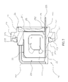
- FIG. 7 is a sectional view of the power connector of the present invention after the hot-melt adhesive layer is applied.
- FIG. 8 is a schematic view illustrating the power connector of the present invention is in use.
- FIG. 9 is another schematic view illustrating the power connector of the present invention is in use.
- FIG. 10 is a three-dimensional exploded view of another embodiment of the power connector of the present invention.
- FIG. 11 is a sectional view of another embodiment of the power connector of the present invention.
- the present invention provides a power connector which comprises a first connecting member ( 10 ) and a second connecting member ( 20 ).
- the first connecting member ( 10 ) has a plurality of first terminals ( 11 ), and a sealing unit ( 12 ) connected to the first connecting member ( 10 ) comprises a plurality of through holes ( 121 ) which are configured to be respectively passed through by the first terminals ( 11 ).
- a side piece ( 122 ) vertical protrudes from an edge of the sealing unit ( 12 ) to form an L-shape.
- a connecting base ( 21 ) formed at an end of the second connecting member ( 20 ) comprises a plurality of L-shaped slots ( 211 ) thereon, and each of the L-shaped slots ( 211 ) has a second terminal ( 22 ) secured therein.
- the other end of the second connecting member ( 20 ) has a first base ( 23 ), and the first base ( 23 ) comprises a connecting surface ( 231 ) which is faced to the connecting base ( 21 ) and an assembling surface ( 232 ) which is located at an opposed side of the connecting surface ( 231 ).
- a second frame ( 24 ) protruding from the assembling surface ( 232 ) has a first housing ( 241 ) therein which is communicated with the L-shaped slots ( 211 ), and each of two lateral edges of the second frame ( 24 ) comprises an engaging slot ( 242 ) at corresponding positions.
- the first base ( 23 ) has two block bodies ( 233 ) protruding from the assembling surface ( 232 ), and the two block bodies ( 233 ) are connected to the second frame ( 24 ) to reinforce the structural strength of the second frame ( 24 ).
- the second frame ( 24 ) is processed to form the two engaging slots ( 242 ) without penetrating through the second frame ( 24 ), thereby enhancing the waterproof effect at positions of the engaging slots ( 242 ).
- the first base ( 23 ) comprises two inner threaded bushings ( 234 ), and each of the inner threaded bushings ( 234 ) has an end extending to the connecting surface ( 231 ) of the first base ( 23 ), and the other end of the inner threaded bushing ( 234 ) is configured to extend to an interior of the block body ( 233 ) so as to enable the block body ( 233 ) to enhance the structural strengths between the first base ( 23 ) and the inner threaded bushing ( 234 ).
- Each of the second terminals ( 22 ) has a pin ( 221 ) protruding toward the first housing ( 241 ), and the pin ( 221 ) is configured to couple with the second frame ( 24 ) and protrude from the first base ( 23 ).
- the second connecting member ( 20 ) has a cover ( 25 ) disposed in the first housing ( 241 ), and each of two ends of the cover ( 25 ) comprises an engaging block ( 251 ) which is configured to engage with the engaging slot ( 242 ) so as to enable the pin ( 221 ) to be clamped between the second frame ( 24 ) and the cover ( 25 ).
- an outer periphery of the cover ( 25 ) has a first packing groove ( 252 ), and a hot-melt adhesive layer ( 26 ) is configured to pave on the first packing groove ( 252 ) to achieve sealing effect on the first packing groove ( 252 ), and the hot-melt adhesive layer ( 26 ) is configured to seal around the pin ( 221 ).
- a second packing groove ( 243 ) is formed on an inner periphery of the second frame ( 24 ) of the second connecting member ( 20 ), and the second packing groove ( 243 ) is adapted to collaborate with the first packing groove ( 252 ) to circle around the pin ( 221 ), and the hot-melt adhesive layer ( 26 ) is adapted to be filled around the pin ( 221 ) with the thickness same as the depth of the first packing groove ( 252 ) and the second packing groove ( 243 ).
- Each of the second terminals ( 22 ) has a first frame ( 222 ) which enables the second terminal ( 22 ) to be secured in the L-shaped slot ( 211 ), and two parallel clamping pieces ( 223 ) are configured to extend from the first frame ( 222 ) toward the second frame ( 24 ), and each of the clamping pieces ( 223 ) has a offset bending thereon.
- an end of the clamping piece ( 223 ) connected to the first frame ( 222 ) is located close to an opening of the L-shaped slot ( 211 ), and the other end of the clamping piece ( 223 ) is located close to the first housing ( 241 ) so as to enable the two clamping pieces ( 223 ) to tightly clamp a lower portion of the first terminal ( 11 ), thereby strengthening the connection when the first terminal ( 11 ) and the second terminal ( 22 ) are connected.
- the second terminals ( 22 ) are installed in the second connecting member ( 20 ) through the first housing ( 241 ), and the second terminals ( 22 ) respectively are secured in the L-shaped slots ( 211 ) through the first frames ( 222 ), and the pin ( 221 ) of the second terminal ( 22 ) is extending out of the second frame ( 24 ).
- the cover ( 25 ) is disposed in the first housing ( 241 ), and the engaging blocks ( 251 ) are respectively engaged with the engaging slots ( 242 ) such that the cover ( 25 ) is filled with the first housing ( 241 ).
- the engagement between the engaging block ( 251 ) and the engaging slot ( 242 ) is configured to secure the relative position of the second frame ( 24 ) and the cover ( 25 ) so as to enforce the structural strength of the assembly.
- the hot-melt adhesive layer ( 26 ) is configured to fill along a way between the second frame ( 24 ) and the cover ( 25 ) so as to fill with the first packing groove ( 252 ) and the second packing groove ( 243 ), and the gap between the second frame ( 24 ) and the cover ( 25 ).
- first packing groove ( 252 ) and the second packing groove ( 243 ) are adapted to circle around the pin ( 221 ) such that the pouring hot-melt adhesive layer ( 26 ) is configured to directly flow in the first packing groove ( 252 ) and the second packing groove ( 243 ) and fill around the pin ( 211 ) to the thickness same as the depth of the first packing groove ( 252 ) and the second packing groove ( 243 ). Since the hot-melt adhesive layer ( 26 ) is only used to seal a single surface, the processing step of the power connector is simplified so as to achieve the practical functions of easy filling and effective waterproof.
- the block bodies ( 233 ) of the first base ( 23 ) are connected to the second frame ( 24 ) so as to enhance the structural strength of the power connector.
- the processed engaging slots ( 242 ) is formed irrelative to the thickness of the second frame ( 24 ) such that positions of the engaging slots ( 242 ) which not penetrate through the second frame ( 24 ) have no need to have additional sealing process to achieve the waterproof effect.
- each of the inner threaded bushings ( 234 ) is formed on the block body ( 233 ) so as to improve the connection between the inner threaded bushing ( 234 ) and the first base ( 23 ) and increase the length of the inner threaded bushing ( 234 ).
- the inner threaded bushing ( 234 ) is made of metal. Through the inner threaded bushings collaborating with the block bodies ( 233 ), the second connecting member ( 20 ) is configured to securely engage with an external component. To sum up, the block bodies ( 233 ) can be used for the engaging slots ( 242 ) and the inner threaded bushings ( 234 ).
- the second connecting member ( 20 ) has a first gasket ( 27 ) disposed on the connecting base ( 21 ), and the first gasket ( 27 ) abutted against the connecting surface ( 231 ) is configured to achieve the waterproof effect when the first base ( 23 ) of the second connecting member ( 20 ) is connected to an external component, wherein the first gasket ( 27 ) is abutted against between the first base ( 23 ) and the external component.
- an annular groove ( 235 ) is formed on the connecting surface ( 231 ) of the first base ( 23 ), and a third frame is connected to an inner edge of the first gasket ( 27 ).
- the third frame is wider than the first gasket ( 27 ) so as to axially protrude from two lateral sides of the first gasket ( 27 ) to form a first protruding portion ( 271 ) and a second protruding portion ( 272 ), wherein the first protruding portion ( 271 ) faced to the second connecting member ( 20 ) is configured to insert into the annular groove ( 235 ), and a second protruding portion ( 272 ) protrudes toward the first connecting member ( 10 ).
- the first connecting member ( 10 ) is locked on a first component ( 30 ), and the first terminals ( 11 ) and the side piece ( 122 ) respectively protrude from an end of the first component ( 30 ).
- the second connecting member ( 20 ) is locked on a second component ( 40 ) through the inner threaded bushings ( 234 ) from inside to outside so as to expose the connecting base ( 21 ) from an end of the second component ( 40 ).
- the second protruding portion ( 272 ) is abutted when the second connecting member ( 20 ) is connected to the second component ( 40 ) so as to enable the first protruding portion ( 271 ) to abut against the annular groove ( 235 ), thereby improving the waterproof effect between the second connecting member ( 20 ) and the second component ( 40 ).
- the first terminals ( 11 ) of the first connecting member ( 10 ) are inserted into the L-shaped slots ( 211 ) of the second connecting member ( 20 ), and the clamping pieces ( 223 ) are configured to clamp the first terminals ( 11 ) so as to electrically connect the first connecting member ( 10 ) to the second connecting member ( 20 ).
- the sealing unit ( 12 ) is collaborated with the side piece ( 122 ) to abut against the L-shaped slots ( 211 ) so as to achieve the waterproof effect of the connection between the first component ( 30 ) and the second component ( 40 ).
- the fixed end of the clamping piece ( 223 ) connected to the first frame ( 222 ) is located adjacent to the opening of the L-shaped slot ( 211 ), which enables two adjacent clamping pieces ( 223 ) to have maximum clamping force such that the second terminals ( 22 ) are configured to tightly clamp the lower portions of the first terminals ( 11 ).
- the first terminals ( 11 ) and the second terminals ( 22 ) are firmly connected.
- the second connecting member ( 20 ) has a plurality of locating slots ( 236 ), and each of the locating slots ( 236 ) is located between two adjacent pins ( 221 ), and a plurality of abutting blocks ( 253 ) are formed at an edge of the cover ( 25 ).
- the first packing groove ( 252 ) is formed across an peripheral edge of the abutting blocks ( 253 ), and the abutting blocks ( 253 ) are accommodated in the locating slots ( 236 ) so as to secured the single pin ( 221 ) between two adjacent abutting blocks ( 253 ), and the pins ( 221 ) are configured to protrude from a surface of the cover ( 25 ) paved with the hot-melt adhesive layer ( 26 ), thereby achieving the effects of easy assembly and waterproof.
- the connecting base ( 21 ) has a plurality of partitions ( 212 ), and each of the partitions is located between two adjacent L-shaped slots ( 211 ).
- a bottom portion ( 213 ) is extended from the partition ( 212 ) to accommodate in the first housing ( 241 ).
- a concaved second housing ( 254 ) is formed on the other surface of the cover ( 25 ) which is faced to the first housing ( 241 ), and the second housing ( 254 ) is extended to the abutting blocks ( 253 ).
- a second gasket ( 28 ) which is waterproof is installed at the second housing ( 254 ), and the second gasket ( 28 ) is directly abutted against the bottom portions ( 213 ) of the partitions ( 212 ), and the second gasket ( 28 ) is configured to surround outer peripheries of the pins ( 221 ) so as to collaborate with the hot-melt adhesive layer ( 26 ) to achieve double waterproof effect.
Abstract
A power connector may comprise a first connecting member and a second connecting member. The first connecting member has a plurality of first terminals, and a connecting base formed at an end of the second connecting member comprises a plurality of L-shaped slots thereon, and each of the L-shaped slots has a second terminal secured therein. When the first terminals and the second terminals are connected, the first connecting member and the second connecting member are electrically connected. The other end of the second connecting member has a first base which comprises a connecting surface and an assembling surface, and a second frame protruding from the assembling surface has a first housing therein. A cover is disposed in the first housing, and an outer periphery of the cover has a first packing groove filled with a hot-melt adhesive layer to achieve sealing effect.
Description
The present invention relates to a power connector and more particularly to a blade-typed power connector.
Generally, it is common that an electronic device connects to a power supply or other circuits through a wire having a male connector and a female connector at two ends thereof, and through quick connection of the male and female connectors, the electronic device can be electrically connected to a power supply. Nevertheless, the connector is a part which has whole circuit and is relatively prone to get breakdown due to humidity. Also, many electronic devices are used in outdoor or the environment which is humid or where temperature varies greatly, or even in the electronic equipment in motion, and the power connector used for these kinds of electronic devices have a high requirement for waterproof function and electrical connection stability. Thus, a waterproof power connector has been developed, which usually comprises a gasket installed at the connection between a shell and an outer cover of the power connector, thereby achieving the waterproof effect, wherein the gasket is put in an interior of the connector first and the outer cover is locked on the shell of the connector so as to tightly clamp the gasket between the outer cover and the shell.
However, the conventional power connector is disadvantageous because: the pressures caused by force point and non-force point are usually different when the outer cover is locked, which results that gasket is not evenly clamped between the outer cover and the shell, thereby reducing the effect of waterproof; and (ii) the gasket may lose its waterproof function due to elastic fatigue or shrinkage after a long period of use; and (iii) it is too many steps for assembly that may lead to misaligned parts, thereby increasing the defect rate and reducing the effect of waterproof. Therefore, there remains a need for a new and improved design for a power connector to overcome the problems presented above.
The present invention provides a power connector which comprises a first connecting member and a second connecting member. The first connecting member has a plurality of first terminals, and a connecting base formed at an end of the second connecting member comprises a plurality of L-shaped slots thereon, and each of the L-shaped slots has a second terminal secured therein. Thus, when the first terminals and the second terminals are connected, the first connecting member and the second connecting member are electrically connected. Furthermore, the other end of the second connecting member has a first base, and the first base comprises a connecting surface which is faced to the connecting base and an assembling surface which is located at an opposed side of the connecting surface. In addition, a second frame protruding from the assembling surface has a first housing therein which is communicated with the L-shaped slots, and each of two lateral edges of the second frame comprises an engaging slot at corresponding positions. Each of the second terminals has a pin protruding toward the first housing, and the pin is configured to couple with the second frame and protrude from the first base. The second connecting member has a cover disposed in the first housing, and each of two ends of the cover comprises an engaging block which is adapted to engage with the engaging slot so as to enable the pin to be clamped between the second frame and the cover. Furthermore, an outer periphery of the cover has a first packing groove, and a hot-melt adhesive layer is configured to pave on the first packing groove to achieve sealing effect around the first packing groove, and the hot-melt adhesive layer is adapted to seal around the pin.
In one embodiment, a second packing groove is formed on an inner periphery of the second frame of the second connecting member, and the second packing groove is adapted to collaborate with the first packing groove to circle around the pin, and the hot-melt adhesive layer is adapted to be filled around the pin with the thickness same as the depth of the first packing groove and the second packing groove.
In another embodiment, the second connecting member has a plurality of locating slots, and each of the locating slots is located between two adjacent pins, and a plurality of abutting blocks are formed at an edge of the cover; the first packing groove is formed across an peripheral edge of the abutting blocks, and the abutting blocks are accommodated in the locating slots so as to secured the single pin between two adjacent abutting blocks, and the pins are configured to protrude from a surface of the cover paved with the hot-melt adhesive layer.
In still another embodiment, the connecting base has a plurality of partitions, and each of the partitions is located between two adjacent L-shaped slots, and a bottom portion is extended from the partition to accommodate in the first housing; a concaved second housing is formed on the other surface of the cover which is faced to the first housing, and the second housing is extended to the abutting blocks; a waterproof second gasket is installed at the second housing, and the second gasket is directly abutted against the bottom portions of the partitions, and the second gasket is configured to surround outer peripheries of the pins.
In a further embodiment, the first base has two block bodies protruding from the assembling surface, and the two block bodies are connected to the second frame to reinforce the structural strength of the second frame; the second frame is processed to form the two engaging slots without penetrating through the second frame.
In still a further embodiment, the first base comprises two inner threaded bushings, and each of the inner threaded bushings has an end extending to the connecting surface of the first base, and the other end of the inner threaded bushing is configured to extend to an interior of the block body so as to enable the block body to enhance the structural strengths between the first base and the inner threaded bushing.
In yet a further embodiment, a sealing unit connected to the first connecting member comprises a plurality of through holes which are configured to be respectively passed through by the first terminals; a side piece vertical protrudes from an edge of the sealing unit to form an L-shape, and the sealing unit collaborated with the side piece is abutted against the L-shaped slot when the first terminal is connected to the second terminal.
In a particular embodiment, the second connecting member has a first gasket disposed on the connecting base, and the first gasket abutted against the connecting surface is configured to achieve the waterproof effect when the first base of the second connecting member is connected to an external component, and the first gasket is abutted against between the first base and the external component.
In another particular embodiment, an annular groove is formed on the connecting surface of the first base, and a third frame is connected to an inner edge of the first gasket; the third frame is wider than the first gasket so as to axially protrude from two lateral sides of the first gasket to form a first protruding portion and a second protruding portion, wherein the first protruding portion faced to the second connecting member is configured to insert into the annular groove, and a second protruding portion protrudes toward the first connecting member, and the second protruding portion is abutted when the second connecting member is connected to an external part so as to enable the first protruding portion to abut against the annular groove.
In still another particular embodiment, each of the second terminals has a first frame which enables the second terminal to be secured in the L-shaped slot, and two parallel clamping pieces are configured to extend from the first frame toward the second frame, and each of the clamping pieces has a offset bending thereon; an end of the clamping piece connected to the first frame is located close to an opening of the L-shaped slot, and the other end of the clamping piece is located close to the first housing so as to enable the two clamping pieces to tightly clamp a lower portion of the first terminal.
Comparing with conventional power connector, the present invention is advantageous because: (i) the cover is disposed in the first housing, and the engaging blocks are respectively engaged with the engaging slots such that the cover is filled with the first housing, and the engagement between the engaging block and the engaging slot is configured to secure the relative position of the second frame and the cover so as to enforce the structural strength of the assembly; (ii) the hot-melt adhesive layer is configured to fill along a way between the second frame and the cover so as to fill with the first packing groove and the second packing groove, and the gap between the second frame and the cover; (iii) the processed engaging slots is formed irrelative to the thickness of the second frame such that positions of the engaging slots which not penetrate through the second frame have no need to have additional sealing process to achieve the waterproof effect; and (iv) each of the inner threaded bushings is formed on the block body so as to improve the connection between the inner threaded bushing and the first base and increase the length of the inner threaded bushing.
The detailed description set forth below is intended as a description of the presently exemplary device provided in accordance with aspects of the present invention and is not intended to represent the only forms in which the present invention may be prepared or utilized. It is to be understood, rather, that the same or equivalent functions and components may be accomplished by different embodiments that are also intended to be encompassed within the spirit and scope of the invention.
Unless defined otherwise, all technical and scientific terms used herein have the same meaning as commonly understood to one of ordinary skill in the art to which this invention belongs. Although any methods, devices and materials similar or equivalent to those described can be used in the practice or testing of the invention, the exemplary methods, devices and materials are now described.
All publications mentioned are incorporated by reference for the purpose of describing and disclosing, for example, the designs and methodologies that are described in the publications that might be used in connection with the presently described invention. The publications listed or discussed above, below and throughout the text are provided solely for their disclosure prior to the filing date of the present application. Nothing herein is to be construed as an admission that the inventors are not entitled to antedate such disclosure by virtue of prior invention.
In order to further understand the goal, characteristics and effect of the present invention, a number of embodiments along with the drawings are illustrated as following:
Referring to FIGS. 1 to 4 , the present invention provides a power connector which comprises a first connecting member (10) and a second connecting member (20). The first connecting member (10) has a plurality of first terminals (11), and a sealing unit (12) connected to the first connecting member (10) comprises a plurality of through holes (121) which are configured to be respectively passed through by the first terminals (11). Moreover, a side piece (122) vertical protrudes from an edge of the sealing unit (12) to form an L-shape. A connecting base (21) formed at an end of the second connecting member (20) comprises a plurality of L-shaped slots (211) thereon, and each of the L-shaped slots (211) has a second terminal (22) secured therein. Thus, when the first terminals (11) and the second terminals (22) are connected, the first connecting member (10) and the second connecting member (20) are electrically connected, and the sealing unit (12) collaborated with the side piece (122) is abutted against the L-shaped slot (211). Furthermore, the other end of the second connecting member (20) has a first base (23), and the first base (23) comprises a connecting surface (231) which is faced to the connecting base (21) and an assembling surface (232) which is located at an opposed side of the connecting surface (231). In addition, a second frame (24) protruding from the assembling surface (232) has a first housing (241) therein which is communicated with the L-shaped slots (211), and each of two lateral edges of the second frame (24) comprises an engaging slot (242) at corresponding positions. Also, the first base (23) has two block bodies (233) protruding from the assembling surface (232), and the two block bodies (233) are connected to the second frame (24) to reinforce the structural strength of the second frame (24). Moreover, the second frame (24) is processed to form the two engaging slots (242) without penetrating through the second frame (24), thereby enhancing the waterproof effect at positions of the engaging slots (242). Additionally, the first base (23) comprises two inner threaded bushings (234), and each of the inner threaded bushings (234) has an end extending to the connecting surface (231) of the first base (23), and the other end of the inner threaded bushing (234) is configured to extend to an interior of the block body (233) so as to enable the block body (233) to enhance the structural strengths between the first base (23) and the inner threaded bushing (234). Each of the second terminals (22) has a pin (221) protruding toward the first housing (241), and the pin (221) is configured to couple with the second frame (24) and protrude from the first base (23). The second connecting member (20) has a cover (25) disposed in the first housing (241), and each of two ends of the cover (25) comprises an engaging block (251) which is configured to engage with the engaging slot (242) so as to enable the pin (221) to be clamped between the second frame (24) and the cover (25). Furthermore, an outer periphery of the cover (25) has a first packing groove (252), and a hot-melt adhesive layer (26) is configured to pave on the first packing groove (252) to achieve sealing effect on the first packing groove (252), and the hot-melt adhesive layer (26) is configured to seal around the pin (221). A second packing groove (243) is formed on an inner periphery of the second frame (24) of the second connecting member (20), and the second packing groove (243) is adapted to collaborate with the first packing groove (252) to circle around the pin (221), and the hot-melt adhesive layer (26) is adapted to be filled around the pin (221) with the thickness same as the depth of the first packing groove (252) and the second packing groove (243). Each of the second terminals (22) has a first frame (222) which enables the second terminal (22) to be secured in the L-shaped slot (211), and two parallel clamping pieces (223) are configured to extend from the first frame (222) toward the second frame (24), and each of the clamping pieces (223) has a offset bending thereon. Also, an end of the clamping piece (223) connected to the first frame (222) is located close to an opening of the L-shaped slot (211), and the other end of the clamping piece (223) is located close to the first housing (241) so as to enable the two clamping pieces (223) to tightly clamp a lower portion of the first terminal (11), thereby strengthening the connection when the first terminal (11) and the second terminal (22) are connected.
Structurally, referring to FIGS. 2 to 7 , the second terminals (22) are installed in the second connecting member (20) through the first housing (241), and the second terminals (22) respectively are secured in the L-shaped slots (211) through the first frames (222), and the pin (221) of the second terminal (22) is extending out of the second frame (24). Thereafter, the cover (25) is disposed in the first housing (241), and the engaging blocks (251) are respectively engaged with the engaging slots (242) such that the cover (25) is filled with the first housing (241). Furthermore, the engagement between the engaging block (251) and the engaging slot (242) is configured to secure the relative position of the second frame (24) and the cover (25) so as to enforce the structural strength of the assembly. Moreover, the hot-melt adhesive layer (26) is configured to fill along a way between the second frame (24) and the cover (25) so as to fill with the first packing groove (252) and the second packing groove (243), and the gap between the second frame (24) and the cover (25). Additionally, the first packing groove (252) and the second packing groove (243) are adapted to circle around the pin (221) such that the pouring hot-melt adhesive layer (26) is configured to directly flow in the first packing groove (252) and the second packing groove (243) and fill around the pin (211) to the thickness same as the depth of the first packing groove (252) and the second packing groove (243). Since the hot-melt adhesive layer (26) is only used to seal a single surface, the processing step of the power connector is simplified so as to achieve the practical functions of easy filling and effective waterproof. Also, the block bodies (233) of the first base (23) are connected to the second frame (24) so as to enhance the structural strength of the power connector. Meanwhile, the processed engaging slots (242) is formed irrelative to the thickness of the second frame (24) such that positions of the engaging slots (242) which not penetrate through the second frame (24) have no need to have additional sealing process to achieve the waterproof effect. Moreover, each of the inner threaded bushings (234) is formed on the block body (233) so as to improve the connection between the inner threaded bushing (234) and the first base (23) and increase the length of the inner threaded bushing (234). In one embodiment, the inner threaded bushing (234) is made of metal. Through the inner threaded bushings collaborating with the block bodies (233), the second connecting member (20) is configured to securely engage with an external component. To sum up, the block bodies (233) can be used for the engaging slots (242) and the inner threaded bushings (234). Additionally, the second connecting member (20) has a first gasket (27) disposed on the connecting base (21), and the first gasket (27) abutted against the connecting surface (231) is configured to achieve the waterproof effect when the first base (23) of the second connecting member (20) is connected to an external component, wherein the first gasket (27) is abutted against between the first base (23) and the external component. Also, an annular groove (235) is formed on the connecting surface (231) of the first base (23), and a third frame is connected to an inner edge of the first gasket (27). The third frame is wider than the first gasket (27) so as to axially protrude from two lateral sides of the first gasket (27) to form a first protruding portion (271) and a second protruding portion (272), wherein the first protruding portion (271) faced to the second connecting member (20) is configured to insert into the annular groove (235), and a second protruding portion (272) protrudes toward the first connecting member (10).
In actual application, referring to FIGS. 8 and 9 , the first connecting member (10) is locked on a first component (30), and the first terminals (11) and the side piece (122) respectively protrude from an end of the first component (30). Also, the second connecting member (20) is locked on a second component (40) through the inner threaded bushings (234) from inside to outside so as to expose the connecting base (21) from an end of the second component (40). Moreover, the second protruding portion (272) is abutted when the second connecting member (20) is connected to the second component (40) so as to enable the first protruding portion (271) to abut against the annular groove (235), thereby improving the waterproof effect between the second connecting member (20) and the second component (40). Furthermore, the first terminals (11) of the first connecting member (10) are inserted into the L-shaped slots (211) of the second connecting member (20), and the clamping pieces (223) are configured to clamp the first terminals (11) so as to electrically connect the first connecting member (10) to the second connecting member (20). In addition, the sealing unit (12) is collaborated with the side piece (122) to abut against the L-shaped slots (211) so as to achieve the waterproof effect of the connection between the first component (30) and the second component (40). Also, the fixed end of the clamping piece (223) connected to the first frame (222) is located adjacent to the opening of the L-shaped slot (211), which enables two adjacent clamping pieces (223) to have maximum clamping force such that the second terminals (22) are configured to tightly clamp the lower portions of the first terminals (11). Thus, the first terminals (11) and the second terminals (22) are firmly connected.
In another embodiment, referring to FIGS. 2, 10 and 11 , the second connecting member (20) has a plurality of locating slots (236), and each of the locating slots (236) is located between two adjacent pins (221), and a plurality of abutting blocks (253) are formed at an edge of the cover (25). The first packing groove (252) is formed across an peripheral edge of the abutting blocks (253), and the abutting blocks (253) are accommodated in the locating slots (236) so as to secured the single pin (221) between two adjacent abutting blocks (253), and the pins (221) are configured to protrude from a surface of the cover (25) paved with the hot-melt adhesive layer (26), thereby achieving the effects of easy assembly and waterproof. Furthermore, the connecting base (21) has a plurality of partitions (212), and each of the partitions is located between two adjacent L-shaped slots (211). Also, a bottom portion (213) is extended from the partition (212) to accommodate in the first housing (241). A concaved second housing (254) is formed on the other surface of the cover (25) which is faced to the first housing (241), and the second housing (254) is extended to the abutting blocks (253). Moreover, a second gasket (28) which is waterproof is installed at the second housing (254), and the second gasket (28) is directly abutted against the bottom portions (213) of the partitions (212), and the second gasket (28) is configured to surround outer peripheries of the pins (221) so as to collaborate with the hot-melt adhesive layer (26) to achieve double waterproof effect.
Having described the invention by the description and illustrations above, it should be understood that these are exemplary of the invention and are not to be considered as limiting. Accordingly, the invention is not to be considered as limited by the foregoing description, but includes any equivalents.
Claims (10)
1. A power connector comprising,
a first connecting member having a plurality of first terminals, and
a second connecting member comprising a connecting base at an end thereof, and the connecting base having a plurality of L-shaped slots thereon, and each of the L-shaped slots comprising a second terminal secured therein; when the first terminals and the second terminals connected, the first connecting member and the second connecting member electrically connected; the other end of the second connecting member having a first base, and the first base comprising a connecting surface which is faced to the connecting base and an assembling surface which is located at an opposed side of the connecting surface; a second frame, which protrudes from the assembling surface, comprising a first housing therein which is communicated with the L-shaped slots, and each of two lateral edges of the second frame having an engaging slot at corresponding positions; each of the second terminals comprising a pin protruding toward the first housing, and the pin configured to couple with the second frame and protrude from the first base; the second connecting member having a cover disposed in the first housing, and each of two ends of the cover comprising an engaging block which is adapted to engage with the engaging slot so as to enable the pin to be clamped between the second frame and the cover; an outer periphery of the cover having a first packing groove, and a hot-melt adhesive layer configured to pave on the first packing groove to achieve sealing effect on the first packing groove, and the hot-melt adhesive layer adapted to seal around the pin.
2. The power connector of claim 1 , wherein a second packing groove is formed on an inner periphery of the second frame of the second connecting member, and the second packing groove is adapted to collaborate with the first packing groove to circle around the pin, and the hot-melt adhesive layer is adapted to be filled around the pin with the thickness same as the depth of the first packing groove and the second packing groove.
3. The power connector of claim 1 , wherein the second connecting member has a plurality of locating slots, and each of the locating slots is located between two adjacent pins; a plurality of abutting blocks are formed at an edge of the cover; the first packing groove is formed across an peripheral edge of the abutting blocks, and the abutting blocks are accommodated in the locating slots so as to secured the single pin between two adjacent abutting blocks, and the pins are configured to protrude from a surface of the cover which is paved with the hot-melt adhesive layer.
4. The power connector of claim 3 , wherein the connecting base has a plurality of partitions, and each of the partitions is located between two adjacent L-shaped slots, and a bottom portion is extended from the partition to accommodate in the first housing; a concaved second housing is formed on the other surface of the cover which is faced to the first housing, and the second housing is extended to the abutting blocks; a waterproof second gasket is installed at the second housing, and the second gasket is directly abutted against the bottom portions of the partitions, and the second gasket is configured to surround outer peripheries of the pins.
5. The power connector of claim 1 , wherein the first base has two block bodies protruding from the assembling surface, and the two block bodies are connected to the second frame to reinforce the structural strength of the second frame; the second frame is processed to form the two engaging slots without penetrating through the second frame.
6. The power connector of claim 5 , wherein the first base comprises two inner threaded bushings, and each of the inner threaded bushings has an end extending to the connecting surface of the first base, and the other end of the inner threaded bushing is configured to extend to an interior of the block body so as to enable the block body to enhance the structural strengths between the first base and the inner threaded bushing.
7. The power connector of claim 1 , wherein a sealing unit connected to the first connecting member comprises a plurality of through holes which are configured to be respectively passed through by the first terminals; a side piece vertical protrudes from an edge of the sealing unit to form an L-shape, and the sealing unit collaborated with the side piece is abutted against the L-shaped slot when the first terminal is connected to the second terminal.
8. The power connector of claim 1 , wherein the second connecting member has a first gasket disposed on the connecting base, and the first gasket abutted against the connecting surface is configured to achieve the waterproof effect when the first base of the second connecting member is connected to an external component, and the first gasket is abutted against between the first base and the external component.
9. The power connector of claim 8 , wherein an annular groove is formed on the connecting surface of the first base, and a third frame is connected to an inner edge of the first gasket; the third frame is wider than the first gasket so as to axially protrude from two lateral sides of the first gasket to form a first protruding portion and a second protruding portion, wherein the first protruding portion faced to the second connecting member is configured to insert into the annular groove, and a second protruding portion protrudes toward the first connecting member, and the second protruding portion is abutted when the second connecting member is connected to an external part so as to enable the first protruding portion to abut against the annular groove.
10. The power connector of claim 1 , wherein each of the second terminals has a first frame which enables the second terminal to be secured in the L-shaped slot, and two parallel clamping pieces are configured to extend from the first frame toward the second frame, and each of the clamping pieces has a offset bending thereon; an end of the clamping piece connected to the first frame is located close to an opening of the L-shaped slot, and the other end of the clamping piece is located close to the first housing so as to enable the two clamping pieces to tightly clamp a lower portion of the first terminal.
Priority Applications (1)
| Application Number | Priority Date | Filing Date | Title |
|---|---|---|---|
| US16/103,908 US10276972B1 (en) | 2018-08-14 | 2018-08-14 | Power connector |
Applications Claiming Priority (1)
| Application Number | Priority Date | Filing Date | Title |
|---|---|---|---|
| US16/103,908 US10276972B1 (en) | 2018-08-14 | 2018-08-14 | Power connector |
Publications (1)
| Publication Number | Publication Date |
|---|---|
| US10276972B1 true US10276972B1 (en) | 2019-04-30 |
Family
ID=66248096
Family Applications (1)
| Application Number | Title | Priority Date | Filing Date |
|---|---|---|---|
| US16/103,908 Active US10276972B1 (en) | 2018-08-14 | 2018-08-14 | Power connector |
Country Status (1)
| Country | Link |
|---|---|
| US (1) | US10276972B1 (en) |
Cited By (6)
| Publication number | Priority date | Publication date | Assignee | Title |
|---|---|---|---|---|
| US20190319396A1 (en) * | 2016-07-06 | 2019-10-17 | Sumitomo Wiring Systems, Ltd. | Connector |
| US11114791B1 (en) * | 2020-02-25 | 2021-09-07 | Chicony Power Technology Co., Ltd. | Connector |
| US11133615B2 (en) * | 2019-04-22 | 2021-09-28 | Foxconn (Kunshan) Computer Connector Co., Ltd. | Electrical connector assembly |
| US11196200B2 (en) * | 2019-06-14 | 2021-12-07 | Foxconn (Kunshan) Computer Connector Co., Ltd. | Electrical connector assembly including plug and receptacle mating portions having spaced front mating surfaces |
| US11309657B1 (en) * | 2021-03-09 | 2022-04-19 | Austin Lai | Blade type electrical connector |
| WO2024062982A1 (en) * | 2022-09-20 | 2024-03-28 | 株式会社ヨコオ | Connector |
Citations (30)
| Publication number | Priority date | Publication date | Assignee | Title |
|---|---|---|---|---|
| US6142825A (en) * | 1997-10-09 | 2000-11-07 | Yazaki Corporation | Waterproof connector and manufacturing method thereof |
| US6461178B1 (en) * | 2001-10-19 | 2002-10-08 | Speed Tech Corp. | Electric connector and adapter arrangement |
| US7422451B2 (en) * | 2006-08-15 | 2008-09-09 | Hon Hai Precision Ind. Co., Ltd. | Electrical connector with ground contacts |
| US8348688B2 (en) * | 2010-11-02 | 2013-01-08 | Cheng Uei Precision Industry Co., Ltd. | Waterproof connector |
| US8388380B1 (en) * | 2011-10-20 | 2013-03-05 | Hon Hai Precision Ind. Co., Ltd | Waterproof connector with board-mounted soldering plate for improved sealing |
| US8827742B2 (en) * | 2012-01-12 | 2014-09-09 | Hon Hai Precision Industry Co., Ltd. | Waterproof electrical connector |
| US9112299B2 (en) * | 2013-04-18 | 2015-08-18 | Hon Hai Precision Industry Co., Ltd. | Waterproof electrical connector and method for making the same |
| US9130301B2 (en) * | 2013-04-18 | 2015-09-08 | Hon Hai Precision Industry Co., Ltd. | Waterproof electrical connector and method for making the same |
| US9331421B2 (en) * | 2014-09-26 | 2016-05-03 | Jess-Link Products Co., Ltd. | Waterproof electric connector module and its waterproof housing |
| US9350110B1 (en) * | 2014-10-30 | 2016-05-24 | Foxconn Interconnect Technology Limited | Electrical connector having improved terminals |
| US9385484B2 (en) * | 2013-11-29 | 2016-07-05 | Foxconn Interconnect Technology Limited | Electrical connector having waterproof function |
| US9553410B2 (en) * | 2014-11-14 | 2017-01-24 | Foxconn Interconnect Technology Limited | Waterproof electrical connector |
| US9564705B2 (en) * | 2012-09-04 | 2017-02-07 | Japan Aviation Electronics Industry, Limited | Waterproof connector |
| US9640899B2 (en) * | 2014-02-20 | 2017-05-02 | Tyco Electronics AMG Korea Ltd. | Waterproof electrical receptacle assembly |
| US9711897B2 (en) * | 2015-08-13 | 2017-07-18 | Molex, Llc | UVA battery connector |
| US9711910B2 (en) * | 2015-02-11 | 2017-07-18 | Foxconn Interconnect Technology Limited | Waterproof electrical connector assembly and method of manufacturing same |
| US9761988B1 (en) * | 2017-01-18 | 2017-09-12 | Assem Technology Co., Ltd. | Waterproof electric connector assembly |
| US9812809B2 (en) * | 2014-10-27 | 2017-11-07 | Japan Aviation Electronics Industry, Limited | Waterproof connector |
| US9812810B2 (en) * | 2014-10-27 | 2017-11-07 | Japan Aviation Electronics Industry, Limited | Waterproof connector |
| US9843128B2 (en) * | 2015-12-03 | 2017-12-12 | Advanced-Connectek Inc. | Waterproof electrical connector |
| US9871317B2 (en) * | 2015-11-27 | 2018-01-16 | Foxconn Interconnect Technology Limited | Waterproof electrical connector |
| US9871318B2 (en) * | 2016-04-28 | 2018-01-16 | Foxconn Interconnect Technology Limited | Waterproof electrical connector having a sealer between conatct module and outer shell |
| US9935393B2 (en) * | 2014-11-14 | 2018-04-03 | Japan Aviation Electronics Industry, Limited | Waterproof connector |
| US9954303B2 (en) * | 2016-01-14 | 2018-04-24 | Foxconn Interconnect Technology Limited | Waterproof electrical connector assembly |
| US9991625B2 (en) * | 2013-06-20 | 2018-06-05 | Ex Company Limited | Waterproof connector and electronic equipment |
| US9997859B2 (en) * | 2016-07-12 | 2018-06-12 | Foxconn Interconnect Technology Limited | Electrical connector having a firmly secured front sealing member |
| US10027052B2 (en) * | 2014-05-26 | 2018-07-17 | Ex Company Limited | Waterproof connection apparatus for electronic equipment, and electronic equipment |
| US10074930B2 (en) * | 2016-05-06 | 2018-09-11 | Foxconn Interconnect Technology Limited | Electrical connector having excellent waterproof property |
| US10096948B2 (en) * | 2016-12-07 | 2018-10-09 | Foxconn Interconnect Technology Limited | Electrical connector having a shielding shell with mounting device and a fixing plate welded to the shielding shell internally |
| US20180337488A1 (en) * | 2017-05-22 | 2018-11-22 | Molex, Llc | Electrical connector |
-
2018
- 2018-08-14 US US16/103,908 patent/US10276972B1/en active Active
Patent Citations (30)
| Publication number | Priority date | Publication date | Assignee | Title |
|---|---|---|---|---|
| US6142825A (en) * | 1997-10-09 | 2000-11-07 | Yazaki Corporation | Waterproof connector and manufacturing method thereof |
| US6461178B1 (en) * | 2001-10-19 | 2002-10-08 | Speed Tech Corp. | Electric connector and adapter arrangement |
| US7422451B2 (en) * | 2006-08-15 | 2008-09-09 | Hon Hai Precision Ind. Co., Ltd. | Electrical connector with ground contacts |
| US8348688B2 (en) * | 2010-11-02 | 2013-01-08 | Cheng Uei Precision Industry Co., Ltd. | Waterproof connector |
| US8388380B1 (en) * | 2011-10-20 | 2013-03-05 | Hon Hai Precision Ind. Co., Ltd | Waterproof connector with board-mounted soldering plate for improved sealing |
| US8827742B2 (en) * | 2012-01-12 | 2014-09-09 | Hon Hai Precision Industry Co., Ltd. | Waterproof electrical connector |
| US9564705B2 (en) * | 2012-09-04 | 2017-02-07 | Japan Aviation Electronics Industry, Limited | Waterproof connector |
| US9112299B2 (en) * | 2013-04-18 | 2015-08-18 | Hon Hai Precision Industry Co., Ltd. | Waterproof electrical connector and method for making the same |
| US9130301B2 (en) * | 2013-04-18 | 2015-09-08 | Hon Hai Precision Industry Co., Ltd. | Waterproof electrical connector and method for making the same |
| US9991625B2 (en) * | 2013-06-20 | 2018-06-05 | Ex Company Limited | Waterproof connector and electronic equipment |
| US9385484B2 (en) * | 2013-11-29 | 2016-07-05 | Foxconn Interconnect Technology Limited | Electrical connector having waterproof function |
| US9640899B2 (en) * | 2014-02-20 | 2017-05-02 | Tyco Electronics AMG Korea Ltd. | Waterproof electrical receptacle assembly |
| US10027052B2 (en) * | 2014-05-26 | 2018-07-17 | Ex Company Limited | Waterproof connection apparatus for electronic equipment, and electronic equipment |
| US9331421B2 (en) * | 2014-09-26 | 2016-05-03 | Jess-Link Products Co., Ltd. | Waterproof electric connector module and its waterproof housing |
| US9812809B2 (en) * | 2014-10-27 | 2017-11-07 | Japan Aviation Electronics Industry, Limited | Waterproof connector |
| US9812810B2 (en) * | 2014-10-27 | 2017-11-07 | Japan Aviation Electronics Industry, Limited | Waterproof connector |
| US9350110B1 (en) * | 2014-10-30 | 2016-05-24 | Foxconn Interconnect Technology Limited | Electrical connector having improved terminals |
| US9553410B2 (en) * | 2014-11-14 | 2017-01-24 | Foxconn Interconnect Technology Limited | Waterproof electrical connector |
| US9935393B2 (en) * | 2014-11-14 | 2018-04-03 | Japan Aviation Electronics Industry, Limited | Waterproof connector |
| US9711910B2 (en) * | 2015-02-11 | 2017-07-18 | Foxconn Interconnect Technology Limited | Waterproof electrical connector assembly and method of manufacturing same |
| US9711897B2 (en) * | 2015-08-13 | 2017-07-18 | Molex, Llc | UVA battery connector |
| US9871317B2 (en) * | 2015-11-27 | 2018-01-16 | Foxconn Interconnect Technology Limited | Waterproof electrical connector |
| US9843128B2 (en) * | 2015-12-03 | 2017-12-12 | Advanced-Connectek Inc. | Waterproof electrical connector |
| US9954303B2 (en) * | 2016-01-14 | 2018-04-24 | Foxconn Interconnect Technology Limited | Waterproof electrical connector assembly |
| US9871318B2 (en) * | 2016-04-28 | 2018-01-16 | Foxconn Interconnect Technology Limited | Waterproof electrical connector having a sealer between conatct module and outer shell |
| US10074930B2 (en) * | 2016-05-06 | 2018-09-11 | Foxconn Interconnect Technology Limited | Electrical connector having excellent waterproof property |
| US9997859B2 (en) * | 2016-07-12 | 2018-06-12 | Foxconn Interconnect Technology Limited | Electrical connector having a firmly secured front sealing member |
| US10096948B2 (en) * | 2016-12-07 | 2018-10-09 | Foxconn Interconnect Technology Limited | Electrical connector having a shielding shell with mounting device and a fixing plate welded to the shielding shell internally |
| US9761988B1 (en) * | 2017-01-18 | 2017-09-12 | Assem Technology Co., Ltd. | Waterproof electric connector assembly |
| US20180337488A1 (en) * | 2017-05-22 | 2018-11-22 | Molex, Llc | Electrical connector |
Cited By (7)
| Publication number | Priority date | Publication date | Assignee | Title |
|---|---|---|---|---|
| US20190319396A1 (en) * | 2016-07-06 | 2019-10-17 | Sumitomo Wiring Systems, Ltd. | Connector |
| US10601167B2 (en) * | 2016-07-06 | 2020-03-24 | Sumitomo Wiring Systems, Ltd. | Connector |
| US11133615B2 (en) * | 2019-04-22 | 2021-09-28 | Foxconn (Kunshan) Computer Connector Co., Ltd. | Electrical connector assembly |
| US11196200B2 (en) * | 2019-06-14 | 2021-12-07 | Foxconn (Kunshan) Computer Connector Co., Ltd. | Electrical connector assembly including plug and receptacle mating portions having spaced front mating surfaces |
| US11114791B1 (en) * | 2020-02-25 | 2021-09-07 | Chicony Power Technology Co., Ltd. | Connector |
| US11309657B1 (en) * | 2021-03-09 | 2022-04-19 | Austin Lai | Blade type electrical connector |
| WO2024062982A1 (en) * | 2022-09-20 | 2024-03-28 | 株式会社ヨコオ | Connector |
Similar Documents
| Publication | Publication Date | Title |
|---|---|---|
| US10276972B1 (en) | Power connector | |
| US9742098B2 (en) | Electrical connector having waterproof function | |
| US10312628B2 (en) | Electrical connector with forward and rearward waterproof sealing | |
| JP3197503U (en) | Waterproof connector module and its waterproof cover | |
| US9871317B2 (en) | Waterproof electrical connector | |
| US9437957B2 (en) | Waterproof connector having internally concealed grounding pin | |
| CA2851272C (en) | Electrical terminals | |
| US7101196B1 (en) | Sealed electrical connector assembly | |
| CN204167590U (en) | Waterproof electrical connector module and waterproof case thereof | |
| US10355396B2 (en) | Electrical connector having front and rear sealing members | |
| KR101506583B1 (en) | Plug connection for directly electrically contacting a circuit board | |
| US10644434B2 (en) | Connector, ingress protection assembly for a connector and method for producing a connector | |
| US10411548B2 (en) | Waterproof structure for electric motor | |
| EP3579351B1 (en) | Waterproof blade type connector | |
| TWI653793B (en) | Electrical connector | |
| TWM592611U (en) | Electrical connector | |
| KR20140044900A (en) | Connector and method for the production thereof | |
| DE102016222639B4 (en) | electronics unit | |
| CN110635301B (en) | Knife type waterproof connector | |
| CN203166159U (en) | Cable connector | |
| WO2024062981A1 (en) | Connector | |
| CN208889990U (en) | Single bend cutting base | |
| TWI635666B (en) | Audio jack and method of making the same | |
| CN104754904B (en) | Electronic device | |
| JP6490571B2 (en) | Sealing structure |
Legal Events
| Date | Code | Title | Description |
|---|---|---|---|
| FEPP | Fee payment procedure |
Free format text: ENTITY STATUS SET TO UNDISCOUNTED (ORIGINAL EVENT CODE: BIG.); ENTITY STATUS OF PATENT OWNER: SMALL ENTITY |
|
| FEPP | Fee payment procedure |
Free format text: ENTITY STATUS SET TO SMALL (ORIGINAL EVENT CODE: SMAL); ENTITY STATUS OF PATENT OWNER: SMALL ENTITY |
|
| STCF | Information on status: patent grant |
Free format text: PATENTED CASE |
|
| MAFP | Maintenance fee payment |
Free format text: PAYMENT OF MAINTENANCE FEE, 4TH YR, SMALL ENTITY (ORIGINAL EVENT CODE: M2551); ENTITY STATUS OF PATENT OWNER: SMALL ENTITY Year of fee payment: 4 |