EP3561963A1 - Cap opening and closing structure and connector for charging - Google Patents
Cap opening and closing structure and connector for charging Download PDFInfo
- Publication number
- EP3561963A1 EP3561963A1 EP17883270.5A EP17883270A EP3561963A1 EP 3561963 A1 EP3561963 A1 EP 3561963A1 EP 17883270 A EP17883270 A EP 17883270A EP 3561963 A1 EP3561963 A1 EP 3561963A1
- Authority
- EP
- European Patent Office
- Prior art keywords
- cap
- engagement
- convex portion
- rotation
- supporting section
- Prior art date
- Legal status (The legal status is an assumption and is not a legal conclusion. Google has not performed a legal analysis and makes no representation as to the accuracy of the status listed.)
- Withdrawn
Links
- 230000002093 peripheral effect Effects 0.000 description 69
- 230000004308 accommodation Effects 0.000 description 30
- 230000004048 modification Effects 0.000 description 17
- 238000012986 modification Methods 0.000 description 17
- 238000009434 installation Methods 0.000 description 7
- 229920003002 synthetic resin Polymers 0.000 description 5
- 239000000057 synthetic resin Substances 0.000 description 5
- 230000000694 effects Effects 0.000 description 4
- 238000013459 approach Methods 0.000 description 3
- 230000008014 freezing Effects 0.000 description 3
- 238000007710 freezing Methods 0.000 description 3
- 239000007788 liquid Substances 0.000 description 3
- XLYOFNOQVPJJNP-UHFFFAOYSA-N water Substances O XLYOFNOQVPJJNP-UHFFFAOYSA-N 0.000 description 3
- 230000006835 compression Effects 0.000 description 2
- 238000007906 compression Methods 0.000 description 2
- 239000002184 metal Substances 0.000 description 2
- 229920005989 resin Polymers 0.000 description 2
- 239000011347 resin Substances 0.000 description 2
- 238000005299 abrasion Methods 0.000 description 1
Images








Classifications
-
- B—PERFORMING OPERATIONS; TRANSPORTING
- B60—VEHICLES IN GENERAL
- B60K—ARRANGEMENT OR MOUNTING OF PROPULSION UNITS OR OF TRANSMISSIONS IN VEHICLES; ARRANGEMENT OR MOUNTING OF PLURAL DIVERSE PRIME-MOVERS IN VEHICLES; AUXILIARY DRIVES FOR VEHICLES; INSTRUMENTATION OR DASHBOARDS FOR VEHICLES; ARRANGEMENTS IN CONNECTION WITH COOLING, AIR INTAKE, GAS EXHAUST OR FUEL SUPPLY OF PROPULSION UNITS IN VEHICLES
- B60K1/00—Arrangement or mounting of electrical propulsion units
- B60K1/04—Arrangement or mounting of electrical propulsion units of the electric storage means for propulsion
-
- B—PERFORMING OPERATIONS; TRANSPORTING
- B60—VEHICLES IN GENERAL
- B60K—ARRANGEMENT OR MOUNTING OF PROPULSION UNITS OR OF TRANSMISSIONS IN VEHICLES; ARRANGEMENT OR MOUNTING OF PLURAL DIVERSE PRIME-MOVERS IN VEHICLES; AUXILIARY DRIVES FOR VEHICLES; INSTRUMENTATION OR DASHBOARDS FOR VEHICLES; ARRANGEMENTS IN CONNECTION WITH COOLING, AIR INTAKE, GAS EXHAUST OR FUEL SUPPLY OF PROPULSION UNITS IN VEHICLES
- B60K15/00—Arrangement in connection with fuel supply of combustion engines or other fuel consuming energy converters, e.g. fuel cells; Mounting or construction of fuel tanks
- B60K15/03—Fuel tanks
- B60K15/04—Tank inlets
- B60K15/05—Inlet covers
-
- B—PERFORMING OPERATIONS; TRANSPORTING
- B60—VEHICLES IN GENERAL
- B60L—PROPULSION OF ELECTRICALLY-PROPELLED VEHICLES; SUPPLYING ELECTRIC POWER FOR AUXILIARY EQUIPMENT OF ELECTRICALLY-PROPELLED VEHICLES; ELECTRODYNAMIC BRAKE SYSTEMS FOR VEHICLES IN GENERAL; MAGNETIC SUSPENSION OR LEVITATION FOR VEHICLES; MONITORING OPERATING VARIABLES OF ELECTRICALLY-PROPELLED VEHICLES; ELECTRIC SAFETY DEVICES FOR ELECTRICALLY-PROPELLED VEHICLES
- B60L50/00—Electric propulsion with power supplied within the vehicle
- B60L50/50—Electric propulsion with power supplied within the vehicle using propulsion power supplied by batteries or fuel cells
-
- B—PERFORMING OPERATIONS; TRANSPORTING
- B60—VEHICLES IN GENERAL
- B60L—PROPULSION OF ELECTRICALLY-PROPELLED VEHICLES; SUPPLYING ELECTRIC POWER FOR AUXILIARY EQUIPMENT OF ELECTRICALLY-PROPELLED VEHICLES; ELECTRODYNAMIC BRAKE SYSTEMS FOR VEHICLES IN GENERAL; MAGNETIC SUSPENSION OR LEVITATION FOR VEHICLES; MONITORING OPERATING VARIABLES OF ELECTRICALLY-PROPELLED VEHICLES; ELECTRIC SAFETY DEVICES FOR ELECTRICALLY-PROPELLED VEHICLES
- B60L53/00—Methods of charging batteries, specially adapted for electric vehicles; Charging stations or on-board charging equipment therefor; Exchange of energy storage elements in electric vehicles
- B60L53/10—Methods of charging batteries, specially adapted for electric vehicles; Charging stations or on-board charging equipment therefor; Exchange of energy storage elements in electric vehicles characterised by the energy transfer between the charging station and the vehicle
- B60L53/14—Conductive energy transfer
- B60L53/16—Connectors, e.g. plugs or sockets, specially adapted for charging electric vehicles
-
- B—PERFORMING OPERATIONS; TRANSPORTING
- B60—VEHICLES IN GENERAL
- B60R—VEHICLES, VEHICLE FITTINGS, OR VEHICLE PARTS, NOT OTHERWISE PROVIDED FOR
- B60R16/00—Electric or fluid circuits specially adapted for vehicles and not otherwise provided for; Arrangement of elements of electric or fluid circuits specially adapted for vehicles and not otherwise provided for
- B60R16/02—Electric or fluid circuits specially adapted for vehicles and not otherwise provided for; Arrangement of elements of electric or fluid circuits specially adapted for vehicles and not otherwise provided for electric constitutive elements
- B60R16/04—Arrangement of batteries
-
- E—FIXED CONSTRUCTIONS
- E05—LOCKS; KEYS; WINDOW OR DOOR FITTINGS; SAFES
- E05B—LOCKS; ACCESSORIES THEREFOR; HANDCUFFS
- E05B83/00—Vehicle locks specially adapted for particular types of wing or vehicle
- E05B83/28—Locks for glove compartments, console boxes, fuel inlet covers or the like
- E05B83/34—Locks for glove compartments, console boxes, fuel inlet covers or the like for fuel inlet covers essentially flush with the vehicle surface
-
- H—ELECTRICITY
- H01—ELECTRIC ELEMENTS
- H01R—ELECTRICALLY-CONDUCTIVE CONNECTIONS; STRUCTURAL ASSOCIATIONS OF A PLURALITY OF MUTUALLY-INSULATED ELECTRICAL CONNECTING ELEMENTS; COUPLING DEVICES; CURRENT COLLECTORS
- H01R13/00—Details of coupling devices of the kinds covered by groups H01R12/70 or H01R24/00 - H01R33/00
- H01R13/44—Means for preventing access to live contacts
- H01R13/447—Shutter or cover plate
- H01R13/453—Shutter or cover plate opened by engagement of counterpart
- H01R13/4532—Rotating shutter
-
- H—ELECTRICITY
- H01—ELECTRIC ELEMENTS
- H01R—ELECTRICALLY-CONDUCTIVE CONNECTIONS; STRUCTURAL ASSOCIATIONS OF A PLURALITY OF MUTUALLY-INSULATED ELECTRICAL CONNECTING ELEMENTS; COUPLING DEVICES; CURRENT COLLECTORS
- H01R13/00—Details of coupling devices of the kinds covered by groups H01R12/70 or H01R24/00 - H01R33/00
- H01R13/46—Bases; Cases
- H01R13/52—Dustproof, splashproof, drip-proof, waterproof, or flameproof cases
- H01R13/5213—Covers
-
- B—PERFORMING OPERATIONS; TRANSPORTING
- B60—VEHICLES IN GENERAL
- B60K—ARRANGEMENT OR MOUNTING OF PROPULSION UNITS OR OF TRANSMISSIONS IN VEHICLES; ARRANGEMENT OR MOUNTING OF PLURAL DIVERSE PRIME-MOVERS IN VEHICLES; AUXILIARY DRIVES FOR VEHICLES; INSTRUMENTATION OR DASHBOARDS FOR VEHICLES; ARRANGEMENTS IN CONNECTION WITH COOLING, AIR INTAKE, GAS EXHAUST OR FUEL SUPPLY OF PROPULSION UNITS IN VEHICLES
- B60K15/00—Arrangement in connection with fuel supply of combustion engines or other fuel consuming energy converters, e.g. fuel cells; Mounting or construction of fuel tanks
- B60K15/03—Fuel tanks
- B60K15/04—Tank inlets
- B60K15/05—Inlet covers
- B60K2015/0515—Arrangements for closing or opening of inlet cover
-
- B—PERFORMING OPERATIONS; TRANSPORTING
- B60—VEHICLES IN GENERAL
- B60K—ARRANGEMENT OR MOUNTING OF PROPULSION UNITS OR OF TRANSMISSIONS IN VEHICLES; ARRANGEMENT OR MOUNTING OF PLURAL DIVERSE PRIME-MOVERS IN VEHICLES; AUXILIARY DRIVES FOR VEHICLES; INSTRUMENTATION OR DASHBOARDS FOR VEHICLES; ARRANGEMENTS IN CONNECTION WITH COOLING, AIR INTAKE, GAS EXHAUST OR FUEL SUPPLY OF PROPULSION UNITS IN VEHICLES
- B60K15/00—Arrangement in connection with fuel supply of combustion engines or other fuel consuming energy converters, e.g. fuel cells; Mounting or construction of fuel tanks
- B60K15/03—Fuel tanks
- B60K15/04—Tank inlets
- B60K15/05—Inlet covers
- B60K2015/0515—Arrangements for closing or opening of inlet cover
- B60K2015/053—Arrangements for closing or opening of inlet cover with hinged connection to the vehicle body
-
- H—ELECTRICITY
- H01—ELECTRIC ELEMENTS
- H01R—ELECTRICALLY-CONDUCTIVE CONNECTIONS; STRUCTURAL ASSOCIATIONS OF A PLURALITY OF MUTUALLY-INSULATED ELECTRICAL CONNECTING ELEMENTS; COUPLING DEVICES; CURRENT COLLECTORS
- H01R2201/00—Connectors or connections adapted for particular applications
- H01R2201/26—Connectors or connections adapted for particular applications for vehicles
-
- Y—GENERAL TAGGING OF NEW TECHNOLOGICAL DEVELOPMENTS; GENERAL TAGGING OF CROSS-SECTIONAL TECHNOLOGIES SPANNING OVER SEVERAL SECTIONS OF THE IPC; TECHNICAL SUBJECTS COVERED BY FORMER USPC CROSS-REFERENCE ART COLLECTIONS [XRACs] AND DIGESTS
- Y02—TECHNOLOGIES OR APPLICATIONS FOR MITIGATION OR ADAPTATION AGAINST CLIMATE CHANGE
- Y02T—CLIMATE CHANGE MITIGATION TECHNOLOGIES RELATED TO TRANSPORTATION
- Y02T10/00—Road transport of goods or passengers
- Y02T10/60—Other road transportation technologies with climate change mitigation effect
- Y02T10/70—Energy storage systems for electromobility, e.g. batteries
-
- Y—GENERAL TAGGING OF NEW TECHNOLOGICAL DEVELOPMENTS; GENERAL TAGGING OF CROSS-SECTIONAL TECHNOLOGIES SPANNING OVER SEVERAL SECTIONS OF THE IPC; TECHNICAL SUBJECTS COVERED BY FORMER USPC CROSS-REFERENCE ART COLLECTIONS [XRACs] AND DIGESTS
- Y02—TECHNOLOGIES OR APPLICATIONS FOR MITIGATION OR ADAPTATION AGAINST CLIMATE CHANGE
- Y02T—CLIMATE CHANGE MITIGATION TECHNOLOGIES RELATED TO TRANSPORTATION
- Y02T10/00—Road transport of goods or passengers
- Y02T10/60—Other road transportation technologies with climate change mitigation effect
- Y02T10/7072—Electromobility specific charging systems or methods for batteries, ultracapacitors, supercapacitors or double-layer capacitors
-
- Y—GENERAL TAGGING OF NEW TECHNOLOGICAL DEVELOPMENTS; GENERAL TAGGING OF CROSS-SECTIONAL TECHNOLOGIES SPANNING OVER SEVERAL SECTIONS OF THE IPC; TECHNICAL SUBJECTS COVERED BY FORMER USPC CROSS-REFERENCE ART COLLECTIONS [XRACs] AND DIGESTS
- Y02—TECHNOLOGIES OR APPLICATIONS FOR MITIGATION OR ADAPTATION AGAINST CLIMATE CHANGE
- Y02T—CLIMATE CHANGE MITIGATION TECHNOLOGIES RELATED TO TRANSPORTATION
- Y02T90/00—Enabling technologies or technologies with a potential or indirect contribution to GHG emissions mitigation
- Y02T90/10—Technologies relating to charging of electric vehicles
- Y02T90/12—Electric charging stations
-
- Y—GENERAL TAGGING OF NEW TECHNOLOGICAL DEVELOPMENTS; GENERAL TAGGING OF CROSS-SECTIONAL TECHNOLOGIES SPANNING OVER SEVERAL SECTIONS OF THE IPC; TECHNICAL SUBJECTS COVERED BY FORMER USPC CROSS-REFERENCE ART COLLECTIONS [XRACs] AND DIGESTS
- Y02—TECHNOLOGIES OR APPLICATIONS FOR MITIGATION OR ADAPTATION AGAINST CLIMATE CHANGE
- Y02T—CLIMATE CHANGE MITIGATION TECHNOLOGIES RELATED TO TRANSPORTATION
- Y02T90/00—Enabling technologies or technologies with a potential or indirect contribution to GHG emissions mitigation
- Y02T90/10—Technologies relating to charging of electric vehicles
- Y02T90/14—Plug-in electric vehicles
Definitions
- the present invention relates to a cap opening and closing structure and a charging connector.
- Conventional vehicle charging connectors having an openable and closable cap provided in a manner covering a connection part connected with a charging connector are used for vehicles such as an electric vehicle (EV) and a plug-in hybrid electric vehicle (PHEV).
- a biasing member such as a spring biases the cap toward a direction opening the cap.
- the cap is locked to a housing when the cap is in a closed state on the housing against a pressing (biasing) force of the spring.
- the cap is opened by the pressing force of the biasing member.
- An object of the present invention is to provide an opening and closing structure of a cap and a charging connector capable of relieving a force for opening the cap and preventing the cap from fluttering when completely opened in simple configurations.
- a cap opening and closing structure includes a housing that is provided with a connection part electrically connected with a connection object outside a vehicle through an opening, a cap that is rotatably supported with respect to the housing in a rotation supporting section provided at an end, closes the opening in a closed position, and exposes the connection part outside the vehicle through the opening in an open position, a first biasing member that biases the cap such that the cap rotates around a rotation axis heading to the open position from the closed position, a pair of a first facing surface and a second facing surface that are formed on the housing and the cap, respectively, and keep facing each other while the cap rotates, a first engagement portion and a second engagement portion that are provided on the first facing surface and the second facing surface, respectively, and a second biasing member that biases one of the first engagement portion and the second engagement portion in an engagement direction where the one engagement portion and the other engagement portion are capable of being engaged with each other in the open position, wherein one of
- the two inclined surfaces may be formed such that the convex portion is engaged with the concave portion with the closely located ends kept in a non-contact state in the open position.
- the first facing surface and the second facing surface may face each other in a rotation axis
- one of the engagement portions may be movably supported with respect to the rotation supporting section in a rotation axis direction
- the second biasing member may be provided between one of the engagement portions and the rotation supporting section and may bias the one engagement portion toward the second facing surface side of the rotation axis direction.
- the first facing surface and the second facing surface may face each other in a radius direction of the rotation supporting section, one of the engagement portions may be movably supported with respect to the rotation supporting section in the radius direction, and the second biasing member may be provided between one of the engagement portions and the rotation supporting section or the housing and may bias the one engagement portion toward the first facing surface side or the second facing surface side of the radius directions.
- the second biasing member in a non-engagement state between the first engagement portion and the second engagement portion, may bring one of the engagement portions into contact with the facing surface facing the engagement portion.
- the first facing surface and the second facing surface may be separated from each other in the radius direction of the rotation supporting section from the open position toward the closed position in the rotation direction.
- a charging connector according to the present invention includes the cap opening and closing structure and a connection part electrically connected between the cap opening and closing structure and a charging connector outside a vehicle.
- the force for opening a cap is suitably controlled, and the cap is prevented from fluttering when completely opened.
- FIG. 1 is a perspective view that illustrates a schematic configuration of the charging connector to which the cap opening and closing structure according to the first embodiment is adapted.
- FIG. 2 is a side view that illustrates a schematic configuration of the charging connector to which the cap opening and closing structure according to the first embodiment is adapted.
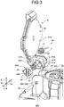
- FIG. 3 is an exploded perspective view that illustrates a schematic configuration of the cap opening and closing structure according to the first embodiment.
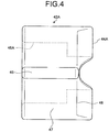
- FIG. 4 is a side view that illustrates a schematic configuration of an inlet damper in the cap opening and closing structure according to the first embodiment.
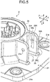
- FIG. 5 is a partial perspective view that illustrates a schematic configuration of an inlet damper supporting unit in the cap opening and closing structure according to the first embodiment.
- FIG. 6 is a sectional view of FIG. 1 along line A-A.
- FIG. 7 is a partial sectional view that illustrates a schematic configuration of the cap opening and closing structure according to the first embodiment.
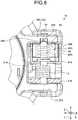
- FIG. 8 is a partial sectional view that illustrates a schematic configuration of the cap opening and closing structure according to the first embodiment.
- FIG. 9 is a schematic view that illustrates engagement operation between a convex portion and a concave portion in the cap opening and closing structure.
- FIG. 1 illustrates a state with the cap in an open position
- FIG. 2 illustrates a state with the cap in a closed position.
- FIG. 1 illustrates a state with the cap in an open position
- FIG. 2 illustrates a state with the cap in a closed position.
- FIG. 1 illustrates a state with the cap in an open position
- FIG. 2 illustrate
- FIG. 5 illustrates a cap supporting unit of a housing supporting the cap.
- FIG. 6 illustrates a sectional surface of a rotation supporting section of a cap in the charging connector with the cap opened.
- FIG. 7 illustrates a state with the cap in the closed position, whereas FIG. 8 illustrates a state with the cap in the open position.
- an X direction in the drawings corresponds to a width direction of the charging connector in the embodiment and also a direction perpendicular to a direction of a rotation axis of the cap.
- a Y direction corresponds to the direction of the rotation axis of the cap in the charging connector in the embodiment and also a direction perpendicular to the X direction.
- a Z direction corresponds to a height direction of the charging connector in the embodiment and also a direction perpendicular to the X direction and the Y direction.
- the Z direction is a height direction of the charging connector and is not limited to a vertical direction.
- a charging connector 100 to which a cap opening and closing structure 1A according to the first embodiment is applied will now be described.
- the charging connector 100 in FIGS. 1 and 2 is installed to a vehicle such as an electric vehicle (EV) and a plug-in hybrid electric vehicle (PHEV) and is electrically connected with a charging connector outside the vehicle to charge a battery mounted on the vehicle.
- the charging connector 100 is fixed to, for example, a body panel of the vehicle.
- the cap opening and closing structure 1A is provided with a housing 2, a torsion spring 3, and a cap 4.
- the housing 2 has a connection part 22b electrically connected with a connection object outside the vehicle through openings 22a.
- the connection object outside the vehicle is a charging connector.
- the housing 2 includes a vehicle body installation unit 21, a housing body 22, a hood unit 23, a hinge pin 24, a cap supporting unit 25, and a cap lock unit 28.
- the vehicle body installation unit 21 is configured by a substantially rectangular plate member made from a synthetic resin.
- the vehicle body installation unit 21 is provided with through-holes 21a serving as mounting holes to a vehicle body panel (not illustrated) at the four corners thereof.
- the vehicle body installation unit 21 is fixed to the vehicle body panel with bolts (not illustrated) passed into the four through-holes 21a and fastened to the vehicle body panel.
- the housing body 22 is configured by a cylindrical member made of a synthetic resin and extends from a substantially center part of the vehicle body installation unit 21 in the height direction.
- the housing body 22 includes the connection part 22b having the openings 22a in the upward direction toward the outside of the vehicle.
- the connection part 22b is electrically connected with the charging connector outside the vehicle through the openings 22a.
- the connection part 22b accommodates inside thereof a terminal fitting (not illustrated) connected to an electric wire (not illustrated) extending from a battery (not illustrated) inside the vehicle.
- the hood unit 23 is made of a synthetic resin and is in a substantially cylindrical shape.
- the hood unit 23 is disposed above the vehicle body installation unit 21 in the Z direction in a manner covering the connection part 22b from the outer periphery thereof.
- the hood unit 23 is provided with the cap supporting unit 25 and the cap lock unit 28 on the outer peripheral surface.
- the hinge pin 24 is an elongated metal rod member and is passed into the torsion spring 3 and the cap 4 in the Y direction, which is the rotation axis direction of the cap 4, through the cap supporting unit 25.
- the hinge pin 24 has the cap 4 rotate with respect to the housing 2 around the rotation axis.
- the cap supporting unit 25 rotatably supports the cap 4 using the hinge pin 24.
- the cap supporting unit 25 is configured with a pair of first supporting unit 26A and second supporting units 27 facing each other with a certain distance interposed therebetween.
- the first supporting unit 26A and the second supporting unit 27 sandwich the cap 4 from the rotation axis direction.
- the first supporting unit 26A has a through-hole 26a into which the hinge pin 24 is passed and a concave portion 29A, on a side surface 30A facing the second supporting unit 27.
- the second supporting unit 27 has a through-hole 27a into which the hinge pin 24 is passed.
- the concave portion 29A corresponds to either a first engagement portion or a second engagement portion and is formed in a groove concaved in the rotation axis direction of the cap 4 and extending in the height direction (the Z direction) perpendicular to the rotation axis direction.
- the concave portion 29A is configured with a bottom surface 290, a pair of ends 290a, a pair of inner side surfaces 291 vertically arranged from the respective ends 290a of the bottom surface 290, and a pair of ends 292A.
- the bottom surface 290 is formed between the ends 290a facing each other in the rotation direction.
- the end 292A is formed at a position where the inner side surface 291 and the side surface 30A perpendicularly contact each other.
- the cap lock unit 28 is a lock mechanism provided on the outer peripheral surface of the hood unit 23 on an opposite side to the cap supporting unit 25 and locking the cap 4 in the closed position.
- the torsion spring 3 is a first biasing member, examples of which include a metallic torsion coil spring.
- the torsion spring 3 biases the cap 4 in a manner having the cap 4 rotate around the rotation axis in a direction from the closed position toward the open position.
- the torsion spring 3 is disposed between the first supporting unit 26A and the second supporting unit 27 along with a rotation supporting section 41b of the cap 4 and has the hinge pin 24 passed on the inner peripheral side thereof.
- the torsion spring 3 has an end locked to an outer peripheral surface 31A of the hood unit 23 of the housing 2 illustrated in FIGS. 5 to 8 and has the other end locked to an outer side surface 41d of the rotation supporting section 41b of the cap 4.
- the cap 4 closes the openings 22a in the closed position and has the connection part 22b exposed outside the vehicle through the openings 22a in the open position.
- the cap 4 is configured with a cap body 41 made from a synthetic resin, an inlet damper 42A made of a synthetic resin, and a metallic inlet damper spring 43A.
- the cap body 41 includes a cover 41a, a rotation supporting section 41b, an accommodation unit 41c, the outer side surface 41d facing the housing 2, and a rotation stop unit 41e.
- the cover 41a is formed by a substantially circular plate member.
- the cover 41a closes the openings 22a in a manner covering the openings 22a when the cap 4 is in the closed position.
- the cover 41a has the connection part 22b exposed through the openings 22a when the cap 4 is in the open position.
- the rotation supporting section 41b is provided on an end of the cover 41a and is rotatably supported with respect to the housing 2.
- the accommodation unit 41c opens in the rotation axis direction of the rotation supporting section 41b, accommodates the inlet damper spring 43A and the inlet damper 42A in order from an opening side, and has the hinge pin 24 passed into the accommodation unit 41c from the other opening side.
- the outer side surface 41d is curved in a circular arc along the rotation direction of the rotation supporting section 41b, in other words, curved along a circular arc (a circular arc surface) having the rotation axis of the cap 4 as the center.
- the rotation stop unit 41e is a projection formed on the outer side surface 41d of the rotation supporting section 41b and extending in the rotation axis direction. When the cap 4 is arranged in the open position, the rotation stop unit 41e comes in contact with the outer peripheral surface 31A of the hood unit 23 and prevents the cap 4 from rotating.
- the inlet damper 42A is movably supported in the rotation axis direction with respect to the rotation supporting section 41b of the cap 4.
- the inlet damper 42A is in a cylindrical shape and is accommodated in the accommodation unit 41c of the rotation supporting section 41b with the inlet damper spring 43A accommodated in the inlet damper 42A.
- the inlet damper 42A is pressed by the inlet damper spring 43A in the rotation axis direction.
- the inlet damper 42A includes a convex portion 44A, a rotation stop projection 45, and a through-hole 46A as illustrated in FIGS. 3 and 4 .
- the convex portion 44A is either a first engagement portion or a second engagement portion, projects from a surface 48 of the inlet damper 42A in the rotation axis direction, and extends in the radius direction perpendicular to the rotation axis direction.
- the surface 48 is a surface facing the side surface 30A of the first supporting unit 26A. More specifically, the surface 48 of the inlet damper 42A and the side surface 30A of the first supporting unit 26A face each other in the rotation axis direction.
- the convex portion 44A is engaged with the concave portion 29A provided on the side surface 30A in the open position of the cap 4. As illustrated in FIG.
- the convex portion 44A has a top surface 440, a pair of closely located ends 441a, two inclined surfaces 441, and a pair of distanced ends 442A.
- the top surface 440 is formed between the closely located ends 441a closely facing each other in the rotation direction.
- the two inclined surfaces 441 are each formed in a manner stretching in the engagement direction from the closely located ends 441a disposed in respective ends of the top surface 440 in the rotation direction toward the pair of distanced ends 442A distantly facing each other in the rotation direction.
- the two inclined surfaces 441 are inclined in a manner widening from the top surface 440 toward the engagement direction (the direction in the dotted allow in FIG. 9 ).
- the two inclined surfaces 441 are formed in a manner having the convex portion 44A engaged with the concave portion 29A in the open position of the cap 4 with the top surface 440 not contacting the bottom surface 290. Engagement between the convex portion 44A and the concave portion 29A indicates a state in which the pair of ends 292A contacts respective two inclined surfaces 441, and this state will be referred to as an engagement state.
- the rotation stop projection 45 is formed on an outer peripheral surface 47 in a manner extending in the rotation axis direction.
- the rotation stop projection 45 is engaged with a concave portion formed on the inner peripheral surface of the accommodation unit 41c when the accommodation unit 41c accommodates the inlet damper 42A.
- the through-hole 46A penetrates in the rotation axis direction and is in a stepped shape in which a part has a smaller inner diameter than the inner diameter of the other part in the rotation axis direction.
- the through-hole 46A accommodates the inlet damper spring 43A and has the hinge pin 24 passed thereinto.
- the inlet damper spring 43A is a second biasing member, examples of which include a metallic compression coil spring.
- the inlet damper spring 43A is accommodated in the accommodation unit 41c coaxially with the rotation axis of the cap 4 along with the inlet damper 42A and has the hinge pin 24 passed on the inner peripheral side.
- the inlet damper spring 43A is provided between the rotation supporting section 41b and the inlet damper 42A and biases the surface 48 of the inlet damper 42A in a rotation axis direction toward the side surface 30A of the first supporting unit 26A of the rotation axis direction. In other words, the inlet damper spring 43A biases the surface 48 in the engagement direction.
- the engagement direction is a direction in which the convex portion 44A and the concave portion 29A as two engagement portions are engaged with each other in the open position of the cap 4.
- the cap 4 and the housing 2 have the surface 48 of the inlet damper 42A in the rotation axis direction and the side surface 30A of the first supporting unit 26A face each other in the rotation axis direction in the closed position of the cap 4.
- the surface 48 is pressed by the inlet damper spring 43A in the rotation axis direction.
- the convex portion 44A of the surface 48 and the concave portion 29A of the side surface 30A are in a non-engagement state.
- the non-engagement state is a state in which neither of the pair of ends 292A of the concave portion 29A contacts with two inclined surfaces 441 of the convex portion 44A.
- the convex portion 44A is pressed by the inlet damper spring 43A in the rotation axis direction and contacts the side surface 30A of the first supporting unit 26A.
- the inlet damper 42A starts rotating around the rotation axis. While the cap 4 rotates, the surface 48 of the inlet damper 42A in the rotation axis direction and the side surface 30A of the first supporting unit 26A keep facing each other. The convex portion 44A slides while keeping the non-engagement state with the concave portion 29A and contacting the side surface 30A of the first supporting unit 26A by the pressing force of the inlet damper spring 43A.
- the convex portion 44A starts engaging with the concave portion 29A and changes from the non-engagement state to the engagement state with the surface 48 and the side surface 30A keeping facing each other in the rotation axis direction.
- the convex portion 44A starts engaging with the concave portion 29A with the top surface 440 sliding on the side surface 30A and approaching the concave portion 29A and with one inclined surface 441 facing opposite to the rotating direction sliding to the corresponding end 292A of the concave portion 29A by means of the pressing force of the inlet damper spring 43A (a half-engagement state).
- the top surface 440 of the convex portion 44A and the bottom surface 290 of the concave portion 29A gradually come closer to each other.
- the half-engagement state is a state in which one of the pair of ends 292A of the concave portion 29A is in contact with one of two inclined surfaces 441 of the convex portion 44A.
- both inclined surfaces 441 contact respective two ends 292A of the concave portion 29A, and the convex portion 44A is pressed in the engagement direction by the inlet damper spring 43A.
- the surface 48 of the inlet damper 42A in the rotation axis direction and the side surface 30A of the first supporting unit 26A keep facing each other in the rotation axis direction without contacting each other.
- the top surface 440 of the convex portion 44A and the bottom surface 290 of the concave portion 29A are positioned closest to each other.
- the convex portion 44A and the concave portion 29A are engaged with each other in the open position of the cap 4 in a manner having the convex portion 44A pressed against the concave portion 29A.
- This configuration can prevent the cap 4 from fluttering when the cap 4 is completely opened.
- the convex portion 44A is pressed to come into contact with the side surface 30A facing the convex portion 44A.
- the convex portion 44A slides in contact with the side surface 30A, which can control the force for opening the cap 4.
- a simple configuration constituted by only resin members and springs is advantageous in reducing the cost.
- the metallic inlet damper spring 43A configured in a manner not exposed outside can keep liquid such as water from entering and prevent a decrease in durability due to, for example, freezing.
- FIGS. 10 and 11 are schematic views that illustrates a schematic configuration of the cap opening and closing structure according to the second embodiment.
- FIG. 12 is a side view that illustrates a schematic configuration of an inlet damper in the cap opening and closing structure according to the second embodiment.
- FIG. 13 is a side view that illustrates a schematic configuration of a first supporting unit of a housing according to the second embodiment.
- FIG. 10 illustrates a state with the cap in a closed position
- FIG. 11 illustrates a state with the cap in an open position.
- FIG. 12 illustrates the rotation supporting section viewed from a rotation axis direction.
- FIG. 13 illustrates the first supporting unit of the housing viewed from the rotation axis direction.
- a first supporting unit 26B has the through-hole 26a into which the hinge pin 24 is passed and a concave portion 29B on a side surface 30B facing the second supporting unit 27.
- the concave portion 29B is either a first engagement portion or a second engagement portion and is formed in a manner concaved in the rotation axis direction of the cap 4.
- the concave portion 29B is configured with the bottom surface 290, the inner side surfaces 291, and the ends 292A as illustrated in FIG. 9 .
- a rotation supporting section 410A is integrally configured with the rotation supporting section 41b.
- the rotation supporting section 410A is accommodated in the accommodation unit 41c of the rotation supporting section 41b.
- the rotation supporting section 410A includes an accommodation unit 410c, an inlet damper spring 43B, an inlet damper 42B, the rotation stop projection 45, and a through-hole 46B.
- the accommodation unit 410c is provided at a position in the radius direction directed outward from the rotation axis and opens in the rotation axis direction from the surface 48 of the rotation supporting section 410A.
- the accommodation unit 410c accommodates the inlet damper spring 43B and the inlet damper 42B and locks them by a known configuration so as not to protrude outside.
- the accommodation unit 410c is configured such that a convex portion 44B of the inlet damper 42B projects from the surface 48 by means of the pressing force of the inlet damper spring 43B.
- the inlet damper spring 43B is a second biasing member, examples of which include a metallic compression coil spring having a small diameter.
- the inlet damper spring 43B is accommodated in the accommodation unit 410c along with the inlet damper 42B.
- the inlet damper spring 43B is provided between the inlet damper 42B and the rotation supporting section 410A and biases the surface 48 of the rotation supporting section 410A in the rotation axis direction toward the side surface 30B of the first supporting unit 26B of the rotation axis direction.
- the inlet damper spring 43B biases the inlet damper 42B in an engagement direction in which the convex portion 44B and the concave portion 29B are engaged with each other in the open position of the cap 4.
- the engagement direction is a direction in which the convex portion 44B and the concave portion 29B as two engagement portions can be engaged with each other in the open position of the cap 4.
- the inlet damper 42B is movably supported in the rotation axis direction with respect to the rotation supporting section 410A.
- the inlet damper 42B is in a cylindrical shape and is accommodated in the accommodation unit 410c of the rotation supporting section 410A.
- the inlet damper 42B has the convex portion 44B at an end thereof.
- the convex portion 44B is either a first engagement portion or a second engagement portion and projects from the surface 48 of the rotation supporting section 410A in the rotation axis direction.
- the surface 48 is a surface facing the side surface 30B of the first supporting unit 26B. More specifically, the surface 48 of the rotation supporting section 410A and the side surface 30B of the first supporting unit 26B face each other in the rotation axis direction.
- the convex portion 44B is engaged with the concave portion 29B provided on the side surface 30B in the open position of the cap 4. As illustrated in FIG. 9 , the convex portion 44B is configured with the top surface 440 and two inclined surfaces 441.
- the through-hole 46B penetrates in the rotation axis direction and has the same inner diameter between a part and the other part in the rotation axis direction.
- the through-hole 46B has the hinge pin 24 passed thereinto.
- the cap 4 and the housing 2 have the surface 48 of the rotation supporting section 410A in the rotation axis direction and the side surface 30B of the first supporting unit 26B face each other in the rotation axis direction in the closed position of the cap 4.
- the inlet damper 42B is pressed by the inlet damper spring 43B in the rotation axis direction.
- the convex portion 44B of the inlet damper 42B and the concave portion 29B of the side surface 30B are in a non-engagement state.
- the non-engagement state is a state in which neither of the pair of ends 292A of the concave portion 29B contacts two inclined surfaces 441 of the convex portion 44B.
- the convex portion 44B is pressed by the inlet damper spring 43B in the rotation axis direction and contacts the side surface 30B of the first supporting unit 26B.
- the rotation supporting section 410A starts rotating around the rotation axis. While the cap 4 rotates, the surface 48 of the rotation supporting section 410A in the rotation axis direction and the side surface 30B of the first supporting unit 26B keep facing each other. The convex portion 44B slides while keeping the non-engagement state with the concave portion 29B and contacting the side surface 30B of the first supporting unit 26B by means of the pressing force of the inlet damper spring 43B.
- the convex portion 44B starts engaging with the concave portion 29B and changes from the non-engagement state to the engagement state with the surface 48 and the side surface 30B keeping facing each other in the rotation axis direction.
- the convex portion 44B starts engaging with the concave portion 29B with the top surface 440 sliding on the side surface 30B and approaching the concave portion 29B and with one inclined surface 441 facing opposite to the rotation direction sliding to the corresponding end 292A of the concave portion 29B by means of the pressing force of the inlet damper spring 43B (a half-engagement state).
- the top surface 440 of the convex portion 44B and the bottom surface 290 of the concave portion 29B gradually come closer to each other.
- the half-engagement state is a state in which one of the pair of ends 292A of the concave portion 29B is in contact with one of two inclined surfaces 441 of the convex portion 44B.
- the convex portion 44B is pressed in the engagement direction by the inlet damper spring 43B with both inclined surfaces 441 contacting respective two ends 292A of the concave portion 29B.
- the surface 48 of the rotation supporting section 410A and the side surface 30B of the first supporting unit 26B keep facing each other in the rotation axis direction without contacting each other.
- the top surface 440 of the convex portion 44B and the bottom surface 290 of the concave portion 29B are positioned closest to each other.
- the convex portion 44B and the concave portion 29B are engaged with each other in the open position of the cap 4 in a manner having the convex portion 44B pressed against the concave portion 29B.
- This configuration can prevent the cap 4 from fluttering when the cap 4 is completely opened.
- the convex portion 44B is pressed to contact the side surface 30B facing the convex portion 44B.
- the convex portion 44B slides in contact with the side surface 30B, thereby enabling the force opening the cap 4 to control.
- a simple configuration constituted by only resin members and springs is advantageous in reducing the cost.
- the metallic inlet damper spring 43B configured in a manner not exposed outside can keep liquid such as water from entering and prevent a decrease in durability due to, for example, freezing.
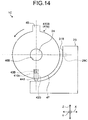
- FIG. 14 is a schematic view that illustrates a schematic configuration of the cap opening and closing structure according to the third embodiment.
- FIG. 15 is another schematic view that illustrates a schematic configuration of the cap opening and closing structure according to the third embodiment.
- FIG. 14 illustrates a state with the cap in the closed position
- FIG. 15 illustrates a state with the cap in the open position.
- the hood unit 23 has a side surface 31B facing the outer peripheral surface 47 of a rotation supporting section 410B of the cap 4 and a concave portion 29C formed on the side surface 31B.
- the side surface 31B is curved in a circular arc along the rotation direction of the rotation supporting section 410B.
- the side surface 31B is formed in a manner keeping facing the outer peripheral surface 47 of the rotation supporting section 410B while the cap 4 rotates.
- the side surface 31B and the outer peripheral surface 47 face each other in the radius direction of the rotation supporting section 410B.
- the concave portion 29C is either a first engagement portion or a second engagement portion and is concaved outward from the side surface 31B in the radius direction of the rotation supporting section 410B.
- the concave portion 29C is configured with the bottom surface 290, the inner side surfaces 291, and the ends 292A as illustrated in FIG. 9 .
- the rotation supporting section 410B is integrally configured with the rotation supporting section 41b.
- the rotation supporting section 410B is accommodated in the accommodation unit 41c of the rotation supporting section 41b.
- the rotation supporting section 410B includes the accommodation unit 410c, the inlet damper spring 43B, the inlet damper 42B, the rotation stop projection 45, and the through-hole 46B.
- the accommodation unit 410c opens from the outer peripheral surface 47 of the rotation supporting section 410B in the radius direction.
- the accommodation unit 410c accommodates the inlet damper spring 43B and the inlet damper 42B and locks them by a known configuration so as not to protrude outside.
- the accommodation unit 410c is configured such that the convex portion 44B of the inlet damper 42B projects from the outer peripheral surface 47 by means of the pressing force of the inlet damper spring 43B.
- the inlet damper spring 43B is provided between the rotation supporting section 410B and the inlet damper 42B and biases the inlet damper 42B outward in the radius direction.
- the inlet damper spring 43B biases the inlet damper 42B in an engagement direction in which the convex portion 44B and the concave portion 29C are engaged with each other in the open position of the cap 4.
- the engagement direction is a direction in which the convex portion 44B and the concave portion 29C can be engaged with each other in the open position of the cap 4.
- the inlet damper 42B is movably supported in the radius direction with respect to the rotation supporting section 410B.
- the convex portion 44B is either a first engagement portion or a second engagement portion and projects from the outer peripheral surface 47 of the rotation supporting section 410B.
- the outer peripheral surface 47 is a surface facing the side surface 31B of the hood unit 23. More specifically, the outer peripheral surface 47 of the rotation supporting section 410B and the side surface 31B of the hood unit 23 face each other in the radius direction.
- the convex portion 44B is engaged with the concave portion 29C provided on the side surface 31B in the open position of the cap 4.
- the cap 4 and the housing 2 have the outer peripheral surface 47 of the rotation supporting section 410B and the side surface 31B of the hood unit 23 face each other in the radius direction in the closed position of the cap 4.
- the inlet damper 42B is pressed by the inlet damper spring 43B in the radius direction.
- the convex portion 44B of the inlet damper 42B and the concave portion 29C of the side surface 31B are in a non-engagement state.
- the non-engagement state is a state in which neither of the pair of ends 292A of the concave portion 29C contacts two inclined surfaces 441 of the convex portion 44B.
- the convex portion 44B is pressed by the inlet damper spring 43B in the radius direction and contacts the side surface 31B of the hood unit 23.
- the rotation supporting section 410B starts rotating around the rotation axis. While the cap 4 rotates, the outer peripheral surface 47 of the rotation supporting section 410B and the side surface 31B of the hood unit 23 keep facing each other.
- the convex portion 44B slides while keeping the non-engagement state with the concave portion 29C and contacting the side surface 31B of the hood unit 23 by means of the pressing force of the inlet damper spring 43B.
- the convex portion 44B starts engaging with the concave portion 29C and changes from the non-engagement state to the engagement state with the outer peripheral surface 47 and the side surface 31B keeping facing each other in the radius direction.
- the convex portion 44B starts engaging with the concave portion 29C with the top surface 440 sliding on the side surface 31B and approaching the concave portion 29C and with one inclined surface 441 facing opposite to the rotation direction sliding to the corresponding end 292A of the concave portion 29C by means of the pressing force of the inlet damper spring 43B (a half-engagement state).
- the top surface 440 of the convex portion 44B and the bottom surface 290 of the concave portion 29C gradually come closer to each other.
- the half-engagement state is a state in which one of the pair of ends 292A of the concave portion 29C is in contact with one of two inclined surfaces 441 of the convex portion 44B.
- the convex portion 44B is pressed in the engagement direction by the inlet damper spring 43B with both inclined surfaces 441 contacting respective two ends 292A of the concave portion 29C.
- the outer peripheral surface 47 of the rotation supporting section 410B and the side surface 31B of the hood unit 23 keep facing each other in the radius direction without contacting each other.
- the top surface 440 of the convex portion 44B and the bottom surface 290 of the concave portion 29C are positioned closest to each other.
- the convex portion 44B and the concave portion 29C are engaged with each other in the open position of the cap 4 in a manner having the convex portion 44B pressed against the concave portion 29C.
- This configuration can prevent the cap 4 from fluttering when the cap 4 is completely opened.
- the convex portion 44B is pressed to contact the side surface 31B facing the convex portion 44B.
- the convex portion 44B slides in contact with the side surface 31B, which can control the force for opening the cap 4.
- Such a simple configuration is advantageous in reducing the cost.
- the configuration can keep liquid such as water from entering, and prevent a decrease in durability due to, for example, freezing.
- FIG. 16 is a schematic view that illustrates a schematic configuration of the cap opening and closing structure according to the fourth embodiment.
- FIG. 17 is another schematic view that illustrates a schematic configuration of the cap opening and closing structure according to the fourth embodiment.
- FIG. 16 illustrates a state with the cap 4 in the closed position
- FIG. 17 illustrates a state with the cap 4 in the open position.
- a cap opening and closing structure 1D and the charging connector 100 according to the fourth embodiment as illustrated in FIGS. 16 and 17 , configurations of a rotation supporting section and a cap supporting unit are different from those of the first embodiment.
- the hood unit 23 has a side surface 31C facing the outer peripheral surface 47 of a rotation supporting section 410C of the cap 4 and a convex portion 29D formed on the side surface 31C.
- the side surface 31C is curved in a circular arc along the rotation direction of the rotation supporting section 410C.
- the side surface 31C is formed in a manner keeping facing the outer peripheral surface 47 of the rotation supporting section 410C while the cap 4 rotates.
- the side surface 31C and the outer peripheral surface 47 face each other in the radius direction of the rotation supporting section 410C.
- the convex portion 29D is either a first engagement portion or a second engagement portion and projects outward from the side surface 31C in the radius direction of the rotation supporting section 410C. As illustrated in FIG. 9 , the convex portion 29D is configured with the top surface 440 and two inclined surfaces 441.
- the rotation supporting section 410C is integrally configured with the rotation supporting section 41b.
- the rotation supporting section 410C is accommodated in the accommodation unit 41c of the rotation supporting section 41b.
- the rotation supporting section 410C includes the accommodation unit 410c, the inlet damper spring 43B, an inlet damper 42C, the rotation stop projection 45, and the through-hole 46B.
- the accommodation unit 410c opens outward from the outer peripheral surface 47 of the rotation supporting section 410C in the radius direction.
- the accommodation unit 410c accommodates the inlet damper spring 43B and the inlet damper 42C and locks them by a known configuration so as not to protrude outside.
- the accommodation unit 410c is configured such that a concave portion 44C of the inlet damper 42C projects from the outer peripheral surface 47 by means of the pressing force of the inlet damper spring 43B.
- the inlet damper spring 43B is provided between the rotation supporting section 410C and the inlet damper 42C and presses the inlet damper 42C outward in the radius direction.
- the inlet damper spring 43B presses the inlet damper 42C in an engagement direction in which the concave portion 44C and the convex portion 29D are engaged with each other in the open position of the cap 4.
- the engagement direction is a direction in which the concave portion 44C and the convex portion 29D can be engaged with each other in the open position of the cap 4.
- the inlet damper 42C is movably supported in the radius direction with respect to the rotation supporting section 410C.
- the convex portion 44C is either a first engagement portion or a second engagement portion and projects from the outer peripheral surface 47 of the rotation supporting section 410C.
- the outer peripheral surface 47 is a surface facing the side surface 31C of the hood unit 23. More specifically, the outer peripheral surface 47 of the rotation supporting section 410C and the side surface 31C of the hood unit 23 face each other in the radius direction.
- the concave portion 44C is engaged with the convex portion 29D provided on the side surface 31C in the open position of the cap 4.
- the concave portion 44C has a substantially U-shaped sectional surface opening in the radius direction when viewed from the rotation axis direction.
- the concave portion 44C has two front ends 44Ca and 44Cb at the opening. Of the front ends 44Ca and 44Cb, the front end 44Ca on the rotation direction side from the closed position toward the open position has a diagonally cut shape.
- the front end 44Ca has the cut surface facing toward the rotation direction side.
- the front end 44Ca has the length in the radius direction smaller than the length of the front end 44Cb.
- the concave portion 44C is preferably made from a hard-to-break flexible metal.
- the corners of the front ends 44Ca and 44Cb are preferably chamfered.
- the cap 4 and the housing 2 have the outer peripheral surface 47 of the rotation supporting section 410C and the side surface 31C of the hood unit 23 face each other in the radius direction in the closed position of the cap 4.
- the inlet damper 42C is pressed by the inlet damper spring 43B in the radius direction.
- the concave portion 44C of the inlet damper 42C and the convex portion 29D of the side surface 31C are in a non-engagement state.
- the non-engagement state is a state in which neither front end 44Ca nor 44Cb of the concave portion 44C contacts two inclined surfaces 441 of the convex portion 29D.
- the concave portion 44C is pressed by the inlet damper spring 43B in the radius direction and brings the front end 44Cb into contact with the side surface 31C of the hood unit 23.
- the rotation supporting section 410C starts rotating around the rotation axis. While the cap 4 rotates, the outer peripheral surface 47 of the rotation supporting section 410C and the side surface 31C of the hood unit 23 keep facing each other.
- the concave portion 44C slides while keeping the non-engagement state with the convex portion 29D and bringing the front end 44Cb into contact with the side surface 31C of the hood unit 23 by means of the pressing force of the inlet damper spring 43B.
- the concave portion 44C starts engaging with the convex portion 29D and changes from the non-engagement state to the engagement state with the outer peripheral surface 47 and the side surface 31C keeping facing each other in the radius direction.
- the concave portion 44C starts engaging with the convex portion 29D with the front end 44Cb sliding on the side surface 31C and approaching the convex portion 29D and with the front end 44Ca sliding on the inclined surface 441 facing opposite to the rotation direction, of two inclined surfaces 441 of the convex portion 29D, by means of the pressing force of the inlet damper spring 43B (a half-engagement state).
- the half-engagement state is a state in which the front end 44Ca of the concave portion 44C is in contact with one of two inclined surfaces 441 of the convex portion 29D.
- the front end 44Ca climbs over the top surface 440 of the convex portion 29D
- the front end 44Cb approaches the inclined surface 441 of the convex portion 29D facing opposite to the rotation direction.
- the bottom surface 290 of the concave portion 44C and the top surface 440 of the convex portion 29D gradually come closer to each other.
- the concave portion 44C is pressed in the engagement direction by the inlet damper spring 43B with the two front ends 44Ca and 44Cb contacting respective inclined surfaces 441 of the convex portion 29D.
- the outer peripheral surface 47 of the rotation supporting section 410C and the side surface 31C of the hood unit 23 keep facing each other in the radius direction without contacting each other.
- the bottom surface 290 of the concave portion 44C and the top surface 440 of the convex portion 29D are positioned closest to each other.
- the concave portion 44C pressed by the inlet damper spring 43B is provided on the outer peripheral surface 47 of the rotation supporting section 410C
- the convex portion 29D is provided on the side surface 31C of the hood unit 23.
- the concave portion 44C is used as the engagement portion on the rotation supporting section side instead of the convex portion 44B
- the convex portion 29D is used as the engagement portion on the hood unit 23 side instead of the concave portion 29C.
- the opening and closing structure 1D and the charging connector 100 can therefore obtain the same advantageous effects as those of the opening and closing structure 1C and the charging connector 100 in the third embodiment.
- FIGS. 18 and 19 are schematic views that illustrates a schematic configuration of a cap opening and closing structure according to a first modification of the third embodiment.
- FIG. 18 illustrates a state with the cap in the closed position
- FIG. 19 illustrates a state with the cap in the open position.
- An opening and closing structure 1E of the cap 4 and the charging connector 100 according to the first modification of the third embodiment are different from the counterparts in the third embodiment in that, as illustrated in FIGS. 18 and 19 , the convex portion 44B is prevented from contacting a side surface 31D of the hood unit 23 when the cap 4 is in the closed position and when the cap 4 is rotating.
- the hood unit 23 has a side surface 31D, a side surface 31Da, an inclined surface 31Db, and a concave portion 29C formed on the side surface 31D.
- the side surface 31D is a surface facing the outer peripheral surface 47 of the rotation supporting section 410B in a position right before the open position of the cap 4 and in the open position of the cap 4.
- the side surface 31D and the outer peripheral surface 47 face each other in the radius direction of the rotation supporting section 410B.
- the side surface 31D connects to at least the inner side surface 291 facing opposite to the rotation direction, of two inner side surfaces 291 of the concave portion 29C.
- the side surface 31Da is curved in a circular arc at least from a position facing the convex portion 44B in the closed position to a position in front of the concave portion 29C along the rotation direction of the rotation supporting section 410B.
- the side surface 31Da and the outer peripheral surface 47 of the rotation supporting section 410B are separated from each other in the radius direction of the rotation supporting section 410B from the open position toward the closed position in the rotation direction.
- a direction from the open position toward the closed position is referred to as a closing direction
- a direction from the closed position toward the open position is referred as an opening direction.
- the side surface 31Da and the outer peripheral surface 47 of the rotation supporting section 410B facing each other are separated from each other in the radius direction of the rotation supporting section 410B toward the closing direction.
- the side surface 31Da is connected to the inclined surface 31Db in front of the concave portion 29C.
- the inclined surface 31Db is connected to the side surface 31D in a manner gradually reducing the distance from the outer peripheral surface 47 along the rotation direction.
- the distance between the side surface 31D and the outer peripheral surface 47 is shorter than the distance between the side surface 31Da and the outer peripheral surface 47.
- the cap 4 and the housing 2 have the outer peripheral surface 47 of the rotation supporting section 410B and the side surface 31D of the hood unit 23 face each other in the radius direction in the closed position of the cap 4.
- the inlet damper 42B is pressed by the inlet damper spring 43B in the radius direction of the rotation supporting section 410B.
- the convex portion 44B of the inlet damper 42B and the concave portion 29C of the side surface 31D are in a non-engagement state.
- the non-engagement state is a state in which neither of the pair of ends 292A of the concave portion 29C contacts two inclined surfaces 441 of the convex portion 44B.
- the convex portion 44B is pressed in the radius direction by the inlet damper spring 43B without contacting the side surface 31Da of the hood unit 23.
- the rotation supporting section 410B starts rotating around the rotation axis. While the cap 4 rotates, the outer peripheral surface 47 of the rotation supporting section 410B and the side surface 31D of the hood unit 23 keep facing each other.
- the convex portion 44B is separated from the concave portion 29C and remains in the non-engagement state without contacting or sliding on the side surface 31Da of the hood unit 23.
- the convex portion 44B slides on the inclined surface 31Db in contact with the inclined surface 31Db by the pressing force of the inlet damper spring 43B and starts engaging with the concave portion 29C.
- the convex portion 44B approaches the concave portion 29C with the top surface 440 sliding on the inclined surface 31Db and the side surface 31D.
- the convex portion 44B starts engaging with the concave portion 29C with the inclined surface 441 facing opposite to the rotation direction sliding to the corresponding end 292A of the concave portion 29C by the pressing force of the inlet damper spring 43B.
- the top surface 440 of the convex portion 44B and the bottom surface 290 of the concave portion 29C gradually come closer to each other.
- the convex portion 44B is pressed in the engagement direction by the inlet damper spring 43B with two inclined surfaces 441 contacting respective two ends 292A of the concave portion 29C.
- the outer peripheral surface 47 of the rotation supporting section 410B and the side surface 31D of the hood unit 23 keep facing each other in the radius direction without contacting each other.
- the top surface 440 of the convex portion 44B and the bottom surface 290 of the concave portion 29C are positioned closest to each other.
- the inlet damper spring 43B biases the convex portion 44B in a manner separated from the side surface 31D facing the convex portion 44B in the non-engagement state between the convex portion 44B and the concave portion 29C.
- This configuration can prevent the convex portion 44B from contacting the side surface 31D of the hood unit 23 when the cap 4 is in the closed position and when the cap 4 is rotating.
- This configuration makes it possible to reduce abrasion of the convex portion 44B caused in contact with the side surface 31D sliding on the side surface 31D.
- FIGS. 20 and 21 are schematic views that illustrates a schematic configuration of a cap opening and closing structure according to a second modification of the third embodiment.
- FIG. 20 illustrates a state with the cap in the closed position
- FIG. 21 illustrates a state with the cap in the open position.
- An opening and closing structure 1F of the cap 4 according to the second modification of the third embodiment is different from the cap opening and closing structure in the third embodiment in that, as illustrated in FIGS. 20 and 21 , the convex portion 44B is prevented from contacting the outer peripheral surface 47 of a rotation supporting section 410D when the cap 4 is in the closed position and when the cap 4 is rotating.
- the opening and closing structure 1E of the cap 4 according to the first modification has the setting positions of a structural unit including the convex portion 44B and a structural unit including a concave portion 44D replacing with each other.
- the hood unit 23 includes the side surface 31B, the accommodation unit 410c, the inlet damper spring 43B, and the inlet damper 42B.
- the side surface 31B is curved in a circular arc along the rotation direction of the rotation supporting section 410D of the cap 4 and faces the outer peripheral surface 47 of the rotation supporting section 410D.
- the side surface 31B is formed in a manner keeping facing the outer peripheral surface 47 of the rotation supporting section 410D while the cap 4 rotates.
- the side surface 31B and the outer peripheral surface 47 face each other in the radius direction of the rotation supporting section 410D.
- the accommodation unit 410c opens from the side surface 31B of the hood unit 23 toward the rotation axis of the rotation supporting section 410D.
- the accommodation unit 410c accommodates the inlet damper spring 43B and the inlet damper 42B and locks them by a known configuration so as not to protrude outside.
- the accommodation unit 410c is configured such that the convex portion 44B of the inlet damper 42B projects from the side surface 31B by means of the pressing force of the inlet damper spring 43B.
- the inlet damper spring 43B is provided between the hood unit 23 and the inlet damper 42B.
- the inlet damper spring 43B biases the inlet damper 42B toward the rotation axis of the rotation supporting section 410D and further biases the inlet damper 42B in an engagement direction in which the convex portion 44B and the concave portion 44D are engaged with each other in the open position of the cap 4.
- the engagement direction is a direction in which the convex portion 44B and the concave portion 44D can be engaged with each other in the open position of the cap 4.
- the inlet damper 42B is movably supported in a direction toward the rotation axis of the rotation supporting section 410D with respect to the hood unit 23.
- the convex portion 44B is either a first engagement portion or a second engagement portion and projects from the side surface 31B of the hood unit 23.
- the rotation supporting section 410D is integrally configured with the rotation supporting section 41b.
- the rotation supporting section 410D is accommodated in the accommodation unit 41c of the rotation supporting section 41b.
- the rotation supporting section 410D includes the concave portion 44D, the rotation stop projection 45, the through-hole 46B, the outer peripheral surface 47, a partial outer peripheral surface 47a, and an inclined surface 47b.
- the concave portion 44D is either a first engagement portion or a second engagement portion and opens outward from the outer peripheral surface 47 of the rotation supporting section 410D in the radius direction.
- the concave portion 44D is engaged with the convex portion 44B of the inlet damper 42B provided on the side surface 31B of the hood unit 23 in the open position of the cap 4.
- the outer peripheral surface 47 is a surface facing the side surface 31B of the hood unit 23 in a position right before the open position of the cap 4 and in the open position of the cap 4.
- the outer peripheral surface 47 and the side surface 31B face each other in the radius direction of the rotation supporting section 410D.
- the outer peripheral surface 47 connects to at least the inner side surface 291 facing opposite to the rotation direction, of the two inner side surfaces 291 of the concave portion 44D.
- the partial outer peripheral surface 47a is curved in a circular arc at least from a position facing the convex portion 44B in the closed position to a position in front of the concave portion 44D along the rotation direction of the rotation supporting section 410D.
- the partial outer peripheral surface 47a and the side surface 31B are separated from each other in the radius direction of the rotation supporting section 410D from the open position toward the closed position in the rotation direction.
- a direction from the open position toward the closed position is referred to as a closing direction
- a direction from the closed position toward the open position is referred as an opening direction.
- the partial outer peripheral surface 47a and the side surface 31B are separated from each other in the radius direction of the rotation supporting section 410D toward the closing direction.
- the partial outer peripheral surface 47a connects to the inclined surface 47b in front of the concave portion 44D.
- the inclined surface 47b is connected to the outer peripheral surface 47 in a manner gradually reducing the distance from the side surface 31B along the rotation direction.
- the distance between the outer peripheral surface 47 and the side surface 31B is smaller than a distance between the partial outer peripheral surface 47a and the side surface 31B.
- the cap 4 and the housing 2 have the outer peripheral surface 47 of the rotation supporting section 410D and the side surface 31B of the hood unit 23 face each other in the radius direction in the closed position of the cap 4.
- the inlet damper 42B is pressed by the inlet damper spring 43B toward the rotation axis of the rotation supporting section 410D.
- the convex portion 44B of the side surface 31B and the concave portion 44D of the rotation supporting section 410D are in a non-engagement state.
- the non-engagement state is a state in which neither the pair of ends 292A of the concave portion 44D contacts two inclined surfaces 441 of the convex portion 44B.
- the convex portion 44B is pressed in the radius direction by the inlet damper spring 43B without contacting the partial outer peripheral surface 47a of the rotation supporting section 410D.
- the rotation supporting section 410D starts rotating around the rotation axis. While the cap 4 rotates, the outer peripheral surface 47 of the rotation supporting section 410D and the side surface 31B of the hood unit 23 keep facing each other.
- the convex portion 44B is separated from the concave portion 44D and remains in the non-engagement state without contacting or sliding on the partial outer peripheral surface 47a of the rotation supporting section 410D.
- the convex portion 44B contacts the inclined surface 47b and slides thereon by the pressing force of the inlet damper spring 43B and starts engaging with the concave portion 44D.
- the convex portion 44B approaches the concave portion 44D with the top surface 440 sliding on the inclined surface 47b and the outer peripheral surface 47.
- the convex portion 44B starts engaging with the concave portion 44D with the inclined surface 441 facing opposite to the rotation direction sliding to the corresponding end 292A of the concave portion 44D by means of the pressing force of the inlet damper spring 43B.
- the top surface 440 of the convex portion 44B and the bottom surface 290 of the concave portion 44D gradually come closer to each other.
- the convex portion 44B is pressed in the engagement direction by the inlet damper spring 43B with two inclined surfaces 441 contacting respective two ends 292A of the concave portion 44D.
- the outer peripheral surface 47 of the rotation supporting section 410D and the side surface 31B of the hood unit 23 keep facing each other in the radius direction without contacting each other.
- the top surface 440 of the convex portion 44B and the bottom surface 290 of the concave portion 44D are positioned closest to each other.
- the opening and closing structure 1F of the cap 4 and the charging connector 100 configured as described above can obtain the same advantageous effects as those of the above-described cap opening and closing structure 1E.
- the convex portion has inclined surfaces, however, the embodiments are not limited to this configuration.
- the concave portion may have inclined surfaces.
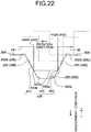
- a convex portion 44E having no inclined surfaces and a concave portion 29E having inclined surfaces may be used as engagement portions.
- the convex portion 44E has the top surface 440, a pair of ends 443a, non-inclined two outer side surfaces 443, and a pair of ends 442B.
- the distance between the ends of the top surface 440 in the rotation direction, which is the distance between the pair of ends 443a, is the same as the distance between the pair of ends 442B.
- the concave portion 29E is configured with the bottom surface 290, a pair of closely located ends 293a, two inclined surfaces 293, and a pair of distanced ends 292B.
- the bottom surface 290 is formed between the closely located ends 293a closely facing each other in the rotation direction.
- the two inclined surfaces 293 each are formed in a manner stretching in the engagement direction from the closely located ends 293a disposed in respective ends of the bottom surface 290 in the rotation direction toward the pair of distanced ends 292B distantly facing each other in the rotation direction.
- the two inclined surfaces 293 are inclined in a manner widening from the bottom surface 290 toward the engagement direction (the direction in the dotted allow in FIG. 22 ).
- the two inclined surfaces 293 are formed such that the convex portion 44E is engaged with the concave portion 29E in the open position of the cap 4 with the bottom surface 290 not contacting the top surface 440.
- the rotation supporting section 41b includes the inlet damper 42A having the convex portion 44A and the inlet damper spring 43A pressing the inlet damper 42A and is engaged with the concave portion 29A included in the first supporting unit 26A, however, the embodiments are not limited to this configuration.
- the first supporting unit 26A may include an inlet damper having a convex portion and an inlet damper spring biasing the inlet damper and is engaged with a concave portion included in the rotation supporting section 41b.
- the concave portion may be provided on the rotation supporting section 41b side, whereas the convex portion may be provided on the first supporting unit 26A side.
- the cap opening and closing structure is applied to a vehicle charging connector.
- the cap opening and closing structure may be applied to a vehicle power supply connector.
- a dual-purpose connector may be used for power supply and charging or separate connectors may be used for respective purposes.
- the ends 292A and 442B are formed at a right angle, however, those ends may be chamfered.
- a pair of inclined surfaces of a convex portion or a concave portion is not limited to plane surfaces but may be symmetric spherical surfaces.
- the convex portion may be hemispherical or may have a semicircle sectional surface.
- the front end 44Ca has a cut surface facing toward the rotation direction side; however, the embodiment is not limited to this configuration. Another cut surface may be formed on the opposite side to the rotation direction side.
- the side surface 31Da may not be necessarily formed in a manner facing the outer peripheral surface 47 of the rotation supporting section 410B.
- the partial outer peripheral surface 47a is not necessarily formed in a manner facing the side surface 31B of the hood unit 23.
Landscapes
- Engineering & Computer Science (AREA)
- Mechanical Engineering (AREA)
- Transportation (AREA)
- Power Engineering (AREA)
- Sustainable Energy (AREA)
- Life Sciences & Earth Sciences (AREA)
- Sustainable Development (AREA)
- Chemical & Material Sciences (AREA)
- Combustion & Propulsion (AREA)
- Connector Housings Or Holding Contact Members (AREA)
- Cooling, Air Intake And Gas Exhaust, And Fuel Tank Arrangements In Propulsion Units (AREA)
- Electric Propulsion And Braking For Vehicles (AREA)
- Arrangement Or Mounting Of Propulsion Units For Vehicles (AREA)
Abstract
Description
- The present invention relates to a cap opening and closing structure and a charging connector.
- Conventional vehicle charging connectors having an openable and closable cap provided in a manner covering a connection part connected with a charging connector are used for vehicles such as an electric vehicle (EV) and a plug-in hybrid electric vehicle (PHEV). In such vehicle charging connectors, a biasing member such as a spring biases the cap toward a direction opening the cap. The cap is locked to a housing when the cap is in a closed state on the housing against a pressing (biasing) force of the spring. When an operator releases the lock, the cap is opened by the pressing force of the biasing member.
- In the vehicle charging connectors, the setting of an excessively large pressing force for pressing the cap causes the cap to burst open, which may decrease the durability of the cap and the opening and closing structure of the cap. To overcome the problem, an opening and closing structure making a smoother motion of the cap has been developed (for example, see Patent Literature 1-4). Citation List
-
- Patent Literature 1: Japanese Patent Application Laid-open No.
2015-115123 - Patent Literature 2: Japanese Patent Application Laid-open No.
2012-221611 - Patent Literature 3: Japanese Patent Application Laid-open No.
2012-18838 - Patent Literature 4: Japanese Patent Application Laid-open No.
2012-15058 - In the vehicle charging connectors described in Patent Literature 1-4, force for opening the cap can be controlled without using an expensive rotary oil dumper, however, the vehicle charging connectors have complicated structures for opening the cap in a smooth motion and therefore need to be further improved.
- An object of the present invention is to provide an opening and closing structure of a cap and a charging connector capable of relieving a force for opening the cap and preventing the cap from fluttering when completely opened in simple configurations.
- In order to achieve the above mentioned object, a cap opening and closing structure according to the present invention includes a housing that is provided with a connection part electrically connected with a connection object outside a vehicle through an opening, a cap that is rotatably supported with respect to the housing in a rotation supporting section provided at an end, closes the opening in a closed position, and exposes the connection part outside the vehicle through the opening in an open position, a first biasing member that biases the cap such that the cap rotates around a rotation axis heading to the open position from the closed position, a pair of a first facing surface and a second facing surface that are formed on the housing and the cap, respectively, and keep facing each other while the cap rotates, a first engagement portion and a second engagement portion that are provided on the first facing surface and the second facing surface, respectively, and a second biasing member that biases one of the first engagement portion and the second engagement portion in an engagement direction where the one engagement portion and the other engagement portion are capable of being engaged with each other in the open position, wherein one of the first engagement portion and the second engagement portion has a convex portion, and the other engagement portion has a concave portion with which the convex portion is engaged by the second biasing member in the open position, at least one of the convex portion and the concave portion has two inclined surfaces facing each other in a rotation direction, and the two inclined surfaces are formed in a manner stretching in the engagement direction from closely located ends closely facing each other toward distanced ends distantly facing each other of the convex portion and the concave portion in the open position.
- In the cap opening and closing structure, the two inclined surfaces may be formed such that the convex portion is engaged with the concave portion with the closely located ends kept in a non-contact state in the open position.
- In the cap opening and closing structure, the first facing surface and the second facing surface may face each other in a rotation axis, one of the engagement portions may be movably supported with respect to the rotation supporting section in a rotation axis direction, and the second biasing member may be provided between one of the engagement portions and the rotation supporting section and may bias the one engagement portion toward the second facing surface side of the rotation axis direction.
- In the cap opening and closing structure, the first facing surface and the second facing surface may face each other in a radius direction of the rotation supporting section, one of the engagement portions may be movably supported with respect to the rotation supporting section in the radius direction, and the second biasing member may be provided between one of the engagement portions and the rotation supporting section or the housing and may bias the one engagement portion toward the first facing surface side or the second facing surface side of the radius directions.
- In the cap opening and closing structure, in a non-engagement state between the first engagement portion and the second engagement portion, the second biasing member may bring one of the engagement portions into contact with the facing surface facing the engagement portion.
- In the cap opening and closing structure, the first facing surface and the second facing surface may be separated from each other in the radius direction of the rotation supporting section from the open position toward the closed position in the rotation direction.
- In order to achieve the above mentioned object, a charging connector according to the present invention includes the cap opening and closing structure and a connection part electrically connected between the cap opening and closing structure and a charging connector outside a vehicle.
- According to the present invention, the force for opening a cap is suitably controlled, and the cap is prevented from fluttering when completely opened.
-
-
FIG. 1 is a perspective view that illustrates a schematic configuration of a charging connector to which a cap opening and closing structure according to a first embodiment is adapted. -
FIG. 2 is a side view that illustrates a schematic configuration of the charging connector to which the cap opening and closing structure according to the first embodiment is adapted. -
FIG. 3 is an exploded perspective view that illustrates a schematic configuration of the cap opening and closing structure according to the first embodiment. -
FIG. 4 is a side view that illustrates a schematic configuration of an inlet damper in the cap opening and closing structure according to the first embodiment. -
FIG. 5 is a partial perspective view that illustrates a schematic configuration of an inlet damper supporting unit in the cap opening and closing structure according to the first embodiment. -
FIG. 6 is a sectional view ofFIG. 1 along A-A. -
FIG. 7 is a partial sectional view that illustrates a schematic configuration of the cap opening and closing structure according to the first embodiment. -
FIG. 8 is a partial sectional view that illustrates a schematic configuration of the cap opening and closing structure according to the first embodiment. -
FIG. 9 is a schematic view that illustrates engagement operation between a convex portion and a concave portion in the cap opening and closing structure. -
FIG. 10 is a schematic view that illustrates a schematic configuration of a cap opening and closing structure according to a second embodiment. -
FIG. 11 is a schematic view that illustrates a schematic configuration of the cap opening and closing structure according to the second embodiment. -
FIG. 12 is a side view that illustrates a schematic configuration of an inlet damper in the cap opening and closing structure according to the second embodiment. -
FIG. 13 is a side view that illustrates a schematic configuration of a first supporting unit of a housing according to the second embodiment. -
FIG. 14 is a schematic view that illustrates a schematic configuration of a cap opening and closing structure according to a third embodiment. -
FIG. 15 is a schematic view that illustrates a schematic configuration of the cap opening and closing structure according to the third embodiment. -
FIG. 16 is a schematic view that illustrates a schematic configuration of a cap opening and closing structure according to a fourth embodiment. -
FIG. 17 is a schematic view that illustrates a schematic configuration of the cap opening and closing structure according to the fourth embodiment. -
FIG. 18 is a schematic view that illustrates a schematic configuration of a cap opening and closing structure according to a first modification of the third embodiment. -
FIG. 19 is a schematic view that illustrates a schematic configuration of the cap opening and closing structure according to the first modification of the third embodiment. -
FIG. 20 is a schematic view that illustrates a schematic configuration of a cap opening and closing structure according to a second modification of the third embodiment. -
FIG. 21 is a schematic view that illustrates a schematic configuration of the cap opening and closing structure according to the second modification of the third embodiment. -
FIG. 22 is a schematic view that illustrates another example of engagement operation of a convex portion and a concave portion in the cap opening and closing structure. - Embodiments according to the present invention will now be described hereinafter in detail with reference to the drawings. It should be noted that the embodiments are not intended to limit the scope of the present invention. Components in the following embodiments include what the skilled person in the art could easily replace with and what are substantially the same. Various omissions, modifications, and changes can be made on the components in the embodiments without departing from the spirit of the present invention.
- A cap opening and closing structure and a charging connector according to a first embodiment will now be described with reference to
FIGS. 1 to 9 .FIG. 1 is a perspective view that illustrates a schematic configuration of the charging connector to which the cap opening and closing structure according to the first embodiment is adapted.FIG. 2 is a side view that illustrates a schematic configuration of the charging connector to which the cap opening and closing structure according to the first embodiment is adapted.FIG. 3 is an exploded perspective view that illustrates a schematic configuration of the cap opening and closing structure according to the first embodiment.FIG. 4 is a side view that illustrates a schematic configuration of an inlet damper in the cap opening and closing structure according to the first embodiment.FIG. 5 is a partial perspective view that illustrates a schematic configuration of an inlet damper supporting unit in the cap opening and closing structure according to the first embodiment.FIG. 6 is a sectional view ofFIG. 1 along line A-A.FIG. 7 is a partial sectional view that illustrates a schematic configuration of the cap opening and closing structure according to the first embodiment.FIG. 8 is a partial sectional view that illustrates a schematic configuration of the cap opening and closing structure according to the first embodiment.FIG. 9 is a schematic view that illustrates engagement operation between a convex portion and a concave portion in the cap opening and closing structure.FIG. 1 illustrates a state with the cap in an open position, whereasFIG. 2 illustrates a state with the cap in a closed position.FIG. 5 illustrates a cap supporting unit of a housing supporting the cap.FIG. 6 illustrates a sectional surface of a rotation supporting section of a cap in the charging connector with the cap opened.FIG. 7 illustrates a state with the cap in the closed position, whereasFIG. 8 illustrates a state with the cap in the open position. - In the following description, an X direction in the drawings corresponds to a width direction of the charging connector in the embodiment and also a direction perpendicular to a direction of a rotation axis of the cap. A Y direction corresponds to the direction of the rotation axis of the cap in the charging connector in the embodiment and also a direction perpendicular to the X direction. A Z direction corresponds to a height direction of the charging connector in the embodiment and also a direction perpendicular to the X direction and the Y direction. The Z direction is a height direction of the charging connector and is not limited to a vertical direction.
- A charging
connector 100 to which a cap opening andclosing structure 1A according to the first embodiment is applied will now be described. The chargingconnector 100 inFIGS. 1 and2 is installed to a vehicle such as an electric vehicle (EV) and a plug-in hybrid electric vehicle (PHEV) and is electrically connected with a charging connector outside the vehicle to charge a battery mounted on the vehicle. The chargingconnector 100 is fixed to, for example, a body panel of the vehicle. The cap opening andclosing structure 1A is provided with ahousing 2, atorsion spring 3, and acap 4. - The
housing 2 has aconnection part 22b electrically connected with a connection object outside the vehicle throughopenings 22a. As an example, the connection object outside the vehicle is a charging connector. More specifically, thehousing 2 includes a vehiclebody installation unit 21, ahousing body 22, ahood unit 23, ahinge pin 24, acap supporting unit 25, and acap lock unit 28. - The vehicle
body installation unit 21 is configured by a substantially rectangular plate member made from a synthetic resin. The vehiclebody installation unit 21 is provided with through-holes 21a serving as mounting holes to a vehicle body panel (not illustrated) at the four corners thereof. The vehiclebody installation unit 21 is fixed to the vehicle body panel with bolts (not illustrated) passed into the four through-holes 21a and fastened to the vehicle body panel. - The
housing body 22 is configured by a cylindrical member made of a synthetic resin and extends from a substantially center part of the vehiclebody installation unit 21 in the height direction. Thehousing body 22 includes theconnection part 22b having theopenings 22a in the upward direction toward the outside of the vehicle. Theconnection part 22b is electrically connected with the charging connector outside the vehicle through theopenings 22a. Theconnection part 22b accommodates inside thereof a terminal fitting (not illustrated) connected to an electric wire (not illustrated) extending from a battery (not illustrated) inside the vehicle. - The
hood unit 23 is made of a synthetic resin and is in a substantially cylindrical shape. Thehood unit 23 is disposed above the vehiclebody installation unit 21 in the Z direction in a manner covering theconnection part 22b from the outer periphery thereof. Thehood unit 23 is provided with thecap supporting unit 25 and thecap lock unit 28 on the outer peripheral surface. - The
hinge pin 24 is an elongated metal rod member and is passed into thetorsion spring 3 and thecap 4 in the Y direction, which is the rotation axis direction of thecap 4, through thecap supporting unit 25. Thehinge pin 24 has thecap 4 rotate with respect to thehousing 2 around the rotation axis. - The
cap supporting unit 25 rotatably supports thecap 4 using thehinge pin 24. Thecap supporting unit 25 is configured with a pair of first supportingunit 26A and second supportingunits 27 facing each other with a certain distance interposed therebetween. In thecap supporting unit 25, the first supportingunit 26A and the second supportingunit 27 sandwich thecap 4 from the rotation axis direction. The first supportingunit 26A has a through-hole 26a into which thehinge pin 24 is passed and aconcave portion 29A, on aside surface 30A facing the second supportingunit 27. The second supportingunit 27 has a through-hole 27a into which thehinge pin 24 is passed. - The
concave portion 29A corresponds to either a first engagement portion or a second engagement portion and is formed in a groove concaved in the rotation axis direction of thecap 4 and extending in the height direction (the Z direction) perpendicular to the rotation axis direction. As illustrated inFIG. 9 , theconcave portion 29A is configured with abottom surface 290, a pair ofends 290a, a pair of inner side surfaces 291 vertically arranged from the respective ends 290a of thebottom surface 290, and a pair ofends 292A. Thebottom surface 290 is formed between theends 290a facing each other in the rotation direction. Theend 292A is formed at a position where theinner side surface 291 and theside surface 30A perpendicularly contact each other. - The
cap lock unit 28 is a lock mechanism provided on the outer peripheral surface of thehood unit 23 on an opposite side to thecap supporting unit 25 and locking thecap 4 in the closed position. - The
torsion spring 3 is a first biasing member, examples of which include a metallic torsion coil spring. Thetorsion spring 3 biases thecap 4 in a manner having thecap 4 rotate around the rotation axis in a direction from the closed position toward the open position. Thetorsion spring 3 is disposed between the first supportingunit 26A and the second supportingunit 27 along with arotation supporting section 41b of thecap 4 and has thehinge pin 24 passed on the inner peripheral side thereof. Thetorsion spring 3 has an end locked to an outerperipheral surface 31A of thehood unit 23 of thehousing 2 illustrated inFIGS. 5 to 8 and has the other end locked to anouter side surface 41d of therotation supporting section 41b of thecap 4. - The
cap 4 closes theopenings 22a in the closed position and has theconnection part 22b exposed outside the vehicle through theopenings 22a in the open position. Thecap 4 is configured with acap body 41 made from a synthetic resin, aninlet damper 42A made of a synthetic resin, and a metallicinlet damper spring 43A. - The
cap body 41 includes acover 41a, arotation supporting section 41b, anaccommodation unit 41c, theouter side surface 41d facing thehousing 2, and arotation stop unit 41e. Thecover 41a is formed by a substantially circular plate member. Thecover 41a closes theopenings 22a in a manner covering theopenings 22a when thecap 4 is in the closed position. Thecover 41a has theconnection part 22b exposed through theopenings 22a when thecap 4 is in the open position. Therotation supporting section 41b is provided on an end of thecover 41a and is rotatably supported with respect to thehousing 2. Theaccommodation unit 41c opens in the rotation axis direction of therotation supporting section 41b, accommodates theinlet damper spring 43A and theinlet damper 42A in order from an opening side, and has thehinge pin 24 passed into theaccommodation unit 41c from the other opening side. Theouter side surface 41d is curved in a circular arc along the rotation direction of therotation supporting section 41b, in other words, curved along a circular arc (a circular arc surface) having the rotation axis of thecap 4 as the center. Therotation stop unit 41e is a projection formed on theouter side surface 41d of therotation supporting section 41b and extending in the rotation axis direction. When thecap 4 is arranged in the open position, therotation stop unit 41e comes in contact with the outerperipheral surface 31A of thehood unit 23 and prevents thecap 4 from rotating. - The
inlet damper 42A is movably supported in the rotation axis direction with respect to therotation supporting section 41b of thecap 4. Theinlet damper 42A is in a cylindrical shape and is accommodated in theaccommodation unit 41c of therotation supporting section 41b with theinlet damper spring 43A accommodated in theinlet damper 42A. Theinlet damper 42A is pressed by theinlet damper spring 43A in the rotation axis direction. Theinlet damper 42A includes aconvex portion 44A, arotation stop projection 45, and a through-hole 46A as illustrated inFIGS. 3 and4 . - The
convex portion 44A is either a first engagement portion or a second engagement portion, projects from asurface 48 of theinlet damper 42A in the rotation axis direction, and extends in the radius direction perpendicular to the rotation axis direction. Thesurface 48 is a surface facing theside surface 30A of the first supportingunit 26A. More specifically, thesurface 48 of theinlet damper 42A and theside surface 30A of the first supportingunit 26A face each other in the rotation axis direction. Theconvex portion 44A is engaged with theconcave portion 29A provided on theside surface 30A in the open position of thecap 4. As illustrated inFIG. 9 , theconvex portion 44A has atop surface 440, a pair of closely located ends 441a, twoinclined surfaces 441, and a pair of distanced ends 442A. Thetop surface 440 is formed between the closely located ends 441a closely facing each other in the rotation direction. The twoinclined surfaces 441 are each formed in a manner stretching in the engagement direction from the closely located ends 441a disposed in respective ends of thetop surface 440 in the rotation direction toward the pair of distanced ends 442A distantly facing each other in the rotation direction. The twoinclined surfaces 441 are inclined in a manner widening from thetop surface 440 toward the engagement direction (the direction in the dotted allow inFIG. 9 ). The twoinclined surfaces 441 are formed in a manner having theconvex portion 44A engaged with theconcave portion 29A in the open position of thecap 4 with thetop surface 440 not contacting thebottom surface 290. Engagement between theconvex portion 44A and theconcave portion 29A indicates a state in which the pair ofends 292A contacts respective twoinclined surfaces 441, and this state will be referred to as an engagement state. - The
rotation stop projection 45 is formed on an outerperipheral surface 47 in a manner extending in the rotation axis direction. Therotation stop projection 45 is engaged with a concave portion formed on the inner peripheral surface of theaccommodation unit 41c when theaccommodation unit 41c accommodates theinlet damper 42A. - The through-
hole 46A penetrates in the rotation axis direction and is in a stepped shape in which a part has a smaller inner diameter than the inner diameter of the other part in the rotation axis direction. The through-hole 46A accommodates theinlet damper spring 43A and has thehinge pin 24 passed thereinto. - The
inlet damper spring 43A is a second biasing member, examples of which include a metallic compression coil spring. Theinlet damper spring 43A is accommodated in theaccommodation unit 41c coaxially with the rotation axis of thecap 4 along with theinlet damper 42A and has thehinge pin 24 passed on the inner peripheral side. Theinlet damper spring 43A is provided between therotation supporting section 41b and theinlet damper 42A and biases thesurface 48 of theinlet damper 42A in a rotation axis direction toward theside surface 30A of the first supportingunit 26A of the rotation axis direction. In other words, theinlet damper spring 43A biases thesurface 48 in the engagement direction. The engagement direction is a direction in which theconvex portion 44A and theconcave portion 29A as two engagement portions are engaged with each other in the open position of thecap 4. - The opening operation leading a cap from the closed position to the open position in the opening and
closing structure 1A of thecap 4 will now be described. As illustrated inFIG. 7 , thecap 4 and thehousing 2 have thesurface 48 of theinlet damper 42A in the rotation axis direction and theside surface 30A of the first supportingunit 26A face each other in the rotation axis direction in the closed position of thecap 4. Thesurface 48 is pressed by theinlet damper spring 43A in the rotation axis direction. Theconvex portion 44A of thesurface 48 and theconcave portion 29A of theside surface 30A are in a non-engagement state. The non-engagement state is a state in which neither of the pair ofends 292A of theconcave portion 29A contacts with twoinclined surfaces 441 of theconvex portion 44A. Theconvex portion 44A is pressed by theinlet damper spring 43A in the rotation axis direction and contacts theside surface 30A of the first supportingunit 26A. - With the
cap lock unit 28 releasing its locking and thecap 4 starting to rotate around the rotation axis from the closed position toward the open position by the pressing force of thetorsion spring 3, theinlet damper 42A starts rotating around the rotation axis. While thecap 4 rotates, thesurface 48 of theinlet damper 42A in the rotation axis direction and theside surface 30A of the first supportingunit 26A keep facing each other. Theconvex portion 44A slides while keeping the non-engagement state with theconcave portion 29A and contacting theside surface 30A of the first supportingunit 26A by the pressing force of theinlet damper spring 43A. - When the
cap 4 comes closer to the open position, theconvex portion 44A starts engaging with theconcave portion 29A and changes from the non-engagement state to the engagement state with thesurface 48 and theside surface 30A keeping facing each other in the rotation axis direction. As illustrated inFIG. 9 , theconvex portion 44A starts engaging with theconcave portion 29A with thetop surface 440 sliding on theside surface 30A and approaching theconcave portion 29A and with oneinclined surface 441 facing opposite to the rotating direction sliding to thecorresponding end 292A of theconcave portion 29A by means of the pressing force of theinlet damper spring 43A (a half-engagement state). Thetop surface 440 of theconvex portion 44A and thebottom surface 290 of theconcave portion 29A gradually come closer to each other. The half-engagement state is a state in which one of the pair ofends 292A of theconcave portion 29A is in contact with one of twoinclined surfaces 441 of theconvex portion 44A. - When the
cap 4 reaches the open position, as illustrated inFIG. 9 , both inclinedsurfaces 441 contact respective twoends 292A of theconcave portion 29A, and theconvex portion 44A is pressed in the engagement direction by theinlet damper spring 43A. When thecap 4 is in the closed position, thesurface 48 of theinlet damper 42A in the rotation axis direction and theside surface 30A of the first supportingunit 26A keep facing each other in the rotation axis direction without contacting each other. In the foregoing state, thetop surface 440 of theconvex portion 44A and thebottom surface 290 of theconcave portion 29A are positioned closest to each other. - With the above-described opening and
closing structure 1A of thecap 4 and the chargingconnector 100, theconvex portion 44A and theconcave portion 29A are engaged with each other in the open position of thecap 4 in a manner having theconvex portion 44A pressed against theconcave portion 29A. This configuration can prevent thecap 4 from fluttering when thecap 4 is completely opened. In the non-engagement state with theconcave portion 29A, theconvex portion 44A is pressed to come into contact with theside surface 30A facing theconvex portion 44A. With this configuration, theconvex portion 44A slides in contact with theside surface 30A, which can control the force for opening thecap 4. Furthermore, such a simple configuration constituted by only resin members and springs is advantageous in reducing the cost. The metallicinlet damper spring 43A configured in a manner not exposed outside can keep liquid such as water from entering and prevent a decrease in durability due to, for example, freezing. - A cap opening and closing structure and the charging
connector 100 according to a second embodiment will now be described with reference toFIGS. 10 to 13 . Each ofFIGS. 10 and11 is a schematic view that illustrates a schematic configuration of the cap opening and closing structure according to the second embodiment.FIG. 12 is a side view that illustrates a schematic configuration of an inlet damper in the cap opening and closing structure according to the second embodiment.FIG. 13 is a side view that illustrates a schematic configuration of a first supporting unit of a housing according to the second embodiment.FIG. 10 illustrates a state with the cap in a closed position, whereasFIG. 11 illustrates a state with the cap in an open position.FIG. 12 illustrates the rotation supporting section viewed from a rotation axis direction.FIG. 13 illustrates the first supporting unit of the housing viewed from the rotation axis direction. - In an opening and
closing structure 1B of thecap 4 and the chargingconnector 100 according to the second embodiment, as illustrated inFIGS. 10 to 13 , configurations of a rotation supporting section and a cap supporting unit are different from those of the first embodiment. Like numerals indicate like components in the above-described first embodiment, and duplicated descriptions of the same configurations, actions, and effects will be omitted as much as possible (which applies to the subsequent embodiments). - In the
housing 2, a first supportingunit 26B has the through-hole 26a into which thehinge pin 24 is passed and aconcave portion 29B on aside surface 30B facing the second supportingunit 27. - The
concave portion 29B is either a first engagement portion or a second engagement portion and is formed in a manner concaved in the rotation axis direction of thecap 4. Theconcave portion 29B is configured with thebottom surface 290, the inner side surfaces 291, and theends 292A as illustrated inFIG. 9 . - In the
cap 4, arotation supporting section 410A is integrally configured with therotation supporting section 41b. Therotation supporting section 410A is accommodated in theaccommodation unit 41c of therotation supporting section 41b. Therotation supporting section 410A includes anaccommodation unit 410c, aninlet damper spring 43B, aninlet damper 42B, the rotation stopprojection 45, and a through-hole 46B. - The
accommodation unit 410c is provided at a position in the radius direction directed outward from the rotation axis and opens in the rotation axis direction from thesurface 48 of therotation supporting section 410A. Theaccommodation unit 410c accommodates theinlet damper spring 43B and theinlet damper 42B and locks them by a known configuration so as not to protrude outside. Theaccommodation unit 410c is configured such that aconvex portion 44B of theinlet damper 42B projects from thesurface 48 by means of the pressing force of theinlet damper spring 43B. - The
inlet damper spring 43B is a second biasing member, examples of which include a metallic compression coil spring having a small diameter. Theinlet damper spring 43B is accommodated in theaccommodation unit 410c along with theinlet damper 42B. Theinlet damper spring 43B is provided between theinlet damper 42B and therotation supporting section 410A and biases thesurface 48 of therotation supporting section 410A in the rotation axis direction toward theside surface 30B of the first supportingunit 26B of the rotation axis direction. Theinlet damper spring 43B biases theinlet damper 42B in an engagement direction in which theconvex portion 44B and theconcave portion 29B are engaged with each other in the open position of thecap 4. The engagement direction is a direction in which theconvex portion 44B and theconcave portion 29B as two engagement portions can be engaged with each other in the open position of thecap 4. - The
inlet damper 42B is movably supported in the rotation axis direction with respect to therotation supporting section 410A. Theinlet damper 42B is in a cylindrical shape and is accommodated in theaccommodation unit 410c of therotation supporting section 410A. Theinlet damper 42B has theconvex portion 44B at an end thereof. - The
convex portion 44B is either a first engagement portion or a second engagement portion and projects from thesurface 48 of therotation supporting section 410A in the rotation axis direction. Thesurface 48 is a surface facing theside surface 30B of the first supportingunit 26B. More specifically, thesurface 48 of therotation supporting section 410A and theside surface 30B of the first supportingunit 26B face each other in the rotation axis direction. Theconvex portion 44B is engaged with theconcave portion 29B provided on theside surface 30B in the open position of thecap 4. As illustrated inFIG. 9 , theconvex portion 44B is configured with thetop surface 440 and twoinclined surfaces 441. - The through-
hole 46B penetrates in the rotation axis direction and has the same inner diameter between a part and the other part in the rotation axis direction. The through-hole 46B has thehinge pin 24 passed thereinto. - The opening operation leading the cap from the closed position to the open position in the opening and
closing structure 1B of thecap 4 will now be described. As illustrated inFIG. 10 , thecap 4 and thehousing 2 have thesurface 48 of therotation supporting section 410A in the rotation axis direction and theside surface 30B of the first supportingunit 26B face each other in the rotation axis direction in the closed position of thecap 4. Theinlet damper 42B is pressed by theinlet damper spring 43B in the rotation axis direction. Theconvex portion 44B of theinlet damper 42B and theconcave portion 29B of theside surface 30B are in a non-engagement state. The non-engagement state is a state in which neither of the pair ofends 292A of theconcave portion 29B contacts twoinclined surfaces 441 of theconvex portion 44B. Theconvex portion 44B is pressed by theinlet damper spring 43B in the rotation axis direction and contacts theside surface 30B of the first supportingunit 26B. - With the
cap lock unit 28 releasing locking and thecap 4 starting rotating around the rotation axis from the closed position toward the open position by the pressing force of thetorsion spring 3, therotation supporting section 410A starts rotating around the rotation axis. While thecap 4 rotates, thesurface 48 of therotation supporting section 410A in the rotation axis direction and theside surface 30B of the first supportingunit 26B keep facing each other. Theconvex portion 44B slides while keeping the non-engagement state with theconcave portion 29B and contacting theside surface 30B of the first supportingunit 26B by means of the pressing force of theinlet damper spring 43B. - When the
cap 4 comes closer to the open position, theconvex portion 44B starts engaging with theconcave portion 29B and changes from the non-engagement state to the engagement state with thesurface 48 and theside surface 30B keeping facing each other in the rotation axis direction. As illustrated inFIG. 9 , theconvex portion 44B starts engaging with theconcave portion 29B with thetop surface 440 sliding on theside surface 30B and approaching theconcave portion 29B and with oneinclined surface 441 facing opposite to the rotation direction sliding to thecorresponding end 292A of theconcave portion 29B by means of the pressing force of theinlet damper spring 43B (a half-engagement state). Thetop surface 440 of theconvex portion 44B and thebottom surface 290 of theconcave portion 29B gradually come closer to each other. The half-engagement state is a state in which one of the pair ofends 292A of theconcave portion 29B is in contact with one of twoinclined surfaces 441 of theconvex portion 44B. - When the
cap 4 reaches the open position, as illustrated inFIG. 11 , theconvex portion 44B is pressed in the engagement direction by theinlet damper spring 43B with bothinclined surfaces 441 contacting respective twoends 292A of theconcave portion 29B. When thecap 4 is in the closed position, thesurface 48 of therotation supporting section 410A and theside surface 30B of the first supportingunit 26B keep facing each other in the rotation axis direction without contacting each other. In this state, thetop surface 440 of theconvex portion 44B and thebottom surface 290 of theconcave portion 29B are positioned closest to each other. - With the above-described opening and
closing structure 1B of thecap 4 and the chargingconnector 100, theconvex portion 44B and theconcave portion 29B are engaged with each other in the open position of thecap 4 in a manner having theconvex portion 44B pressed against theconcave portion 29B. This configuration can prevent thecap 4 from fluttering when thecap 4 is completely opened. In the non-engagement state with theconcave portion 29B, theconvex portion 44B is pressed to contact theside surface 30B facing theconvex portion 44B. With this configuration, theconvex portion 44B slides in contact with theside surface 30B, thereby enabling the force opening thecap 4 to control. Furthermore, such a simple configuration constituted by only resin members and springs is advantageous in reducing the cost. The metallicinlet damper spring 43B configured in a manner not exposed outside can keep liquid such as water from entering and prevent a decrease in durability due to, for example, freezing. - A cap opening and closing structure according to a third embodiment will now be described with reference to
FIGS. 14 and15 .FIG. 14 is a schematic view that illustrates a schematic configuration of the cap opening and closing structure according to the third embodiment.FIG. 15 is another schematic view that illustrates a schematic configuration of the cap opening and closing structure according to the third embodiment.FIG. 14 illustrates a state with the cap in the closed position, whereasFIG. 15 illustrates a state with the cap in the open position. - In an opening and
closing structure 1C of thecap 4 and the chargingconnector 100 according to the third embodiment, as illustrated inFIGS. 14 and15 , configurations of a rotation supporting section and a cap supporting unit are different from those of the first embodiment. - In the
housing 2, thehood unit 23 has aside surface 31B facing the outerperipheral surface 47 of arotation supporting section 410B of thecap 4 and aconcave portion 29C formed on theside surface 31B. Theside surface 31B is curved in a circular arc along the rotation direction of therotation supporting section 410B. Theside surface 31B is formed in a manner keeping facing the outerperipheral surface 47 of therotation supporting section 410B while thecap 4 rotates. Theside surface 31B and the outerperipheral surface 47 face each other in the radius direction of therotation supporting section 410B. - The
concave portion 29C is either a first engagement portion or a second engagement portion and is concaved outward from theside surface 31B in the radius direction of therotation supporting section 410B. Theconcave portion 29C is configured with thebottom surface 290, the inner side surfaces 291, and theends 292A as illustrated inFIG. 9 . - In the
cap 4, therotation supporting section 410B is integrally configured with therotation supporting section 41b. Therotation supporting section 410B is accommodated in theaccommodation unit 41c of therotation supporting section 41b. Therotation supporting section 410B includes theaccommodation unit 410c, theinlet damper spring 43B, theinlet damper 42B, the rotation stopprojection 45, and the through-hole 46B. - The
accommodation unit 410c opens from the outerperipheral surface 47 of therotation supporting section 410B in the radius direction. Theaccommodation unit 410c accommodates theinlet damper spring 43B and theinlet damper 42B and locks them by a known configuration so as not to protrude outside. Theaccommodation unit 410c is configured such that theconvex portion 44B of theinlet damper 42B projects from the outerperipheral surface 47 by means of the pressing force of theinlet damper spring 43B. - The
inlet damper spring 43B is provided between therotation supporting section 410B and theinlet damper 42B and biases theinlet damper 42B outward in the radius direction. Theinlet damper spring 43B biases theinlet damper 42B in an engagement direction in which theconvex portion 44B and theconcave portion 29C are engaged with each other in the open position of thecap 4. The engagement direction is a direction in which theconvex portion 44B and theconcave portion 29C can be engaged with each other in the open position of thecap 4. - The
inlet damper 42B is movably supported in the radius direction with respect to therotation supporting section 410B. Theconvex portion 44B is either a first engagement portion or a second engagement portion and projects from the outerperipheral surface 47 of therotation supporting section 410B. The outerperipheral surface 47 is a surface facing theside surface 31B of thehood unit 23. More specifically, the outerperipheral surface 47 of therotation supporting section 410B and theside surface 31B of thehood unit 23 face each other in the radius direction. Theconvex portion 44B is engaged with theconcave portion 29C provided on theside surface 31B in the open position of thecap 4. - The opening operation leading the cap from the closed position to the open position in the opening and
closing structure 1C of thecap 4 will now be described. As illustrated inFIG. 14 , thecap 4 and thehousing 2 have the outerperipheral surface 47 of therotation supporting section 410B and theside surface 31B of thehood unit 23 face each other in the radius direction in the closed position of thecap 4. Theinlet damper 42B is pressed by theinlet damper spring 43B in the radius direction. Theconvex portion 44B of theinlet damper 42B and theconcave portion 29C of theside surface 31B are in a non-engagement state. The non-engagement state is a state in which neither of the pair ofends 292A of theconcave portion 29C contacts twoinclined surfaces 441 of theconvex portion 44B. Theconvex portion 44B is pressed by theinlet damper spring 43B in the radius direction and contacts theside surface 31B of thehood unit 23. - With the
cap lock unit 28 releasing locking and thecap 4 starting rotating around the rotation axis from the closed position toward the open position by means of the pressing force of thetorsion spring 3, therotation supporting section 410B starts rotating around the rotation axis. While thecap 4 rotates, the outerperipheral surface 47 of therotation supporting section 410B and theside surface 31B of thehood unit 23 keep facing each other. Theconvex portion 44B slides while keeping the non-engagement state with theconcave portion 29C and contacting theside surface 31B of thehood unit 23 by means of the pressing force of theinlet damper spring 43B. - When the
cap 4 comes closer to the open position, theconvex portion 44B starts engaging with theconcave portion 29C and changes from the non-engagement state to the engagement state with the outerperipheral surface 47 and theside surface 31B keeping facing each other in the radius direction. As illustrated inFIG. 9 , theconvex portion 44B starts engaging with theconcave portion 29C with thetop surface 440 sliding on theside surface 31B and approaching theconcave portion 29C and with oneinclined surface 441 facing opposite to the rotation direction sliding to thecorresponding end 292A of theconcave portion 29C by means of the pressing force of theinlet damper spring 43B (a half-engagement state). Thetop surface 440 of theconvex portion 44B and thebottom surface 290 of theconcave portion 29C gradually come closer to each other. The half-engagement state is a state in which one of the pair ofends 292A of theconcave portion 29C is in contact with one of twoinclined surfaces 441 of theconvex portion 44B. - When the
cap 4 reaches the open position, as illustrated inFIGS. 15 and9 , theconvex portion 44B is pressed in the engagement direction by theinlet damper spring 43B with bothinclined surfaces 441 contacting respective twoends 292A of theconcave portion 29C. When thecap 4 is in the closed position, the outerperipheral surface 47 of therotation supporting section 410B and theside surface 31B of thehood unit 23 keep facing each other in the radius direction without contacting each other. In this state, thetop surface 440 of theconvex portion 44B and thebottom surface 290 of theconcave portion 29C are positioned closest to each other. - With the above-described opening and
closing structure 1C of thecap 4 and the chargingconnector 100, theconvex portion 44B and theconcave portion 29C are engaged with each other in the open position of thecap 4 in a manner having theconvex portion 44B pressed against theconcave portion 29C. This configuration can prevent thecap 4 from fluttering when thecap 4 is completely opened. In the non-engagement state with theconcave portion 29C, theconvex portion 44B is pressed to contact theside surface 31B facing theconvex portion 44B. With this configuration, theconvex portion 44B slides in contact with theside surface 31B, which can control the force for opening thecap 4. Furthermore, such a simple configuration is advantageous in reducing the cost. The configuration can keep liquid such as water from entering, and prevent a decrease in durability due to, for example, freezing. - A cap opening and closing structure and the charging
connector 100 according to a fourth embodiment will now be described with reference toFIGS. 16 and17 .FIG. 16 is a schematic view that illustrates a schematic configuration of the cap opening and closing structure according to the fourth embodiment.FIG. 17 is another schematic view that illustrates a schematic configuration of the cap opening and closing structure according to the fourth embodiment.FIG. 16 illustrates a state with thecap 4 in the closed position, whereasFIG. 17 illustrates a state with thecap 4 in the open position. - In a cap opening and
closing structure 1D and the chargingconnector 100 according to the fourth embodiment, as illustrated inFIGS. 16 and17 , configurations of a rotation supporting section and a cap supporting unit are different from those of the first embodiment. - In the
housing 2, thehood unit 23 has aside surface 31C facing the outerperipheral surface 47 of arotation supporting section 410C of thecap 4 and aconvex portion 29D formed on theside surface 31C. Theside surface 31C is curved in a circular arc along the rotation direction of therotation supporting section 410C. Theside surface 31C is formed in a manner keeping facing the outerperipheral surface 47 of therotation supporting section 410C while thecap 4 rotates. The side surface 31C and the outerperipheral surface 47 face each other in the radius direction of therotation supporting section 410C. - The
convex portion 29D is either a first engagement portion or a second engagement portion and projects outward from theside surface 31C in the radius direction of therotation supporting section 410C. As illustrated inFIG. 9 , theconvex portion 29D is configured with thetop surface 440 and twoinclined surfaces 441. - In the
cap 4, therotation supporting section 410C is integrally configured with therotation supporting section 41b. Therotation supporting section 410C is accommodated in theaccommodation unit 41c of therotation supporting section 41b. Therotation supporting section 410C includes theaccommodation unit 410c, theinlet damper spring 43B, aninlet damper 42C, the rotation stopprojection 45, and the through-hole 46B. - The
accommodation unit 410c opens outward from the outerperipheral surface 47 of therotation supporting section 410C in the radius direction. Theaccommodation unit 410c accommodates theinlet damper spring 43B and theinlet damper 42C and locks them by a known configuration so as not to protrude outside. Theaccommodation unit 410c is configured such that aconcave portion 44C of theinlet damper 42C projects from the outerperipheral surface 47 by means of the pressing force of theinlet damper spring 43B. - The
inlet damper spring 43B is provided between therotation supporting section 410C and theinlet damper 42C and presses theinlet damper 42C outward in the radius direction. Theinlet damper spring 43B presses theinlet damper 42C in an engagement direction in which theconcave portion 44C and theconvex portion 29D are engaged with each other in the open position of thecap 4. The engagement direction is a direction in which theconcave portion 44C and theconvex portion 29D can be engaged with each other in the open position of thecap 4. - The
inlet damper 42C is movably supported in the radius direction with respect to therotation supporting section 410C. Theconvex portion 44C is either a first engagement portion or a second engagement portion and projects from the outerperipheral surface 47 of therotation supporting section 410C. The outerperipheral surface 47 is a surface facing theside surface 31C of thehood unit 23. More specifically, the outerperipheral surface 47 of therotation supporting section 410C and theside surface 31C of thehood unit 23 face each other in the radius direction. - The
concave portion 44C is engaged with theconvex portion 29D provided on theside surface 31C in the open position of thecap 4. Theconcave portion 44C has a substantially U-shaped sectional surface opening in the radius direction when viewed from the rotation axis direction. Theconcave portion 44C has two front ends 44Ca and 44Cb at the opening. Of the front ends 44Ca and 44Cb, the front end 44Ca on the rotation direction side from the closed position toward the open position has a diagonally cut shape. The front end 44Ca has the cut surface facing toward the rotation direction side. The front end 44Ca has the length in the radius direction smaller than the length of the front end 44Cb. Theconcave portion 44C is preferably made from a hard-to-break flexible metal. The corners of the front ends 44Ca and 44Cb are preferably chamfered. - The opening operation leading the cap from the closed position to the open position in the opening and
closing structure 1D of thecap 4 will now be described. As illustrated inFIG. 16 , thecap 4 and thehousing 2 have the outerperipheral surface 47 of therotation supporting section 410C and theside surface 31C of thehood unit 23 face each other in the radius direction in the closed position of thecap 4. Theinlet damper 42C is pressed by theinlet damper spring 43B in the radius direction. Theconcave portion 44C of theinlet damper 42C and theconvex portion 29D of theside surface 31C are in a non-engagement state. The non-engagement state is a state in which neither front end 44Ca nor 44Cb of theconcave portion 44C contacts twoinclined surfaces 441 of theconvex portion 29D. Theconcave portion 44C is pressed by theinlet damper spring 43B in the radius direction and brings the front end 44Cb into contact with theside surface 31C of thehood unit 23. - With the
cap lock unit 28 releasing locking and thecap 4 starting rotating around the rotation axis from the closed position toward the open position by means of the pressing force of thetorsion spring 3, therotation supporting section 410C starts rotating around the rotation axis. While thecap 4 rotates, the outerperipheral surface 47 of therotation supporting section 410C and theside surface 31C of thehood unit 23 keep facing each other. Theconcave portion 44C slides while keeping the non-engagement state with theconvex portion 29D and bringing the front end 44Cb into contact with theside surface 31C of thehood unit 23 by means of the pressing force of theinlet damper spring 43B. - When the
cap 4 comes closer to the open position, theconcave portion 44C starts engaging with theconvex portion 29D and changes from the non-engagement state to the engagement state with the outerperipheral surface 47 and theside surface 31C keeping facing each other in the radius direction. Theconcave portion 44C starts engaging with theconvex portion 29D with the front end 44Cb sliding on theside surface 31C and approaching theconvex portion 29D and with the front end 44Ca sliding on theinclined surface 441 facing opposite to the rotation direction, of twoinclined surfaces 441 of theconvex portion 29D, by means of the pressing force of theinlet damper spring 43B (a half-engagement state). The half-engagement state is a state in which the front end 44Ca of theconcave portion 44C is in contact with one of twoinclined surfaces 441 of theconvex portion 29D. In theconcave portion 44C, when the front end 44Ca climbs over thetop surface 440 of theconvex portion 29D, the front end 44Cb approaches theinclined surface 441 of theconvex portion 29D facing opposite to the rotation direction. Thebottom surface 290 of theconcave portion 44C and thetop surface 440 of theconvex portion 29D gradually come closer to each other. - When the
cap 4 reaches the open position, theconcave portion 44C is pressed in the engagement direction by theinlet damper spring 43B with the two front ends 44Ca and 44Cb contacting respectiveinclined surfaces 441 of theconvex portion 29D. When thecap 4 is in the closed position, the outerperipheral surface 47 of therotation supporting section 410C and theside surface 31C of thehood unit 23 keep facing each other in the radius direction without contacting each other. In this state, thebottom surface 290 of theconcave portion 44C and thetop surface 440 of theconvex portion 29D are positioned closest to each other. - In the above-described opening and
closing structure 1D of thecap 4 and the chargingconnector 100, theconcave portion 44C pressed by theinlet damper spring 43B is provided on the outerperipheral surface 47 of therotation supporting section 410C, and theconvex portion 29D is provided on theside surface 31C of thehood unit 23. For the above-described opening andclosing structure 1C and the chargingconnector 100, in this embodiment, theconcave portion 44C is used as the engagement portion on the rotation supporting section side instead of theconvex portion 44B, and theconvex portion 29D is used as the engagement portion on thehood unit 23 side instead of theconcave portion 29C. The opening andclosing structure 1D and the chargingconnector 100 can therefore obtain the same advantageous effects as those of the opening andclosing structure 1C and the chargingconnector 100 in the third embodiment. - Each of
FIGS. 18 and19 is a schematic view that illustrates a schematic configuration of a cap opening and closing structure according to a first modification of the third embodiment.FIG. 18 illustrates a state with the cap in the closed position, whereasFIG. 19 illustrates a state with the cap in the open position. - An opening and
closing structure 1E of thecap 4 and the chargingconnector 100 according to the first modification of the third embodiment are different from the counterparts in the third embodiment in that, as illustrated inFIGS. 18 and19 , theconvex portion 44B is prevented from contacting aside surface 31D of thehood unit 23 when thecap 4 is in the closed position and when thecap 4 is rotating. - In the
housing 2, thehood unit 23 has aside surface 31D, a side surface 31Da, an inclined surface 31Db, and aconcave portion 29C formed on theside surface 31D. Theside surface 31D is a surface facing the outerperipheral surface 47 of therotation supporting section 410B in a position right before the open position of thecap 4 and in the open position of thecap 4. Theside surface 31D and the outerperipheral surface 47 face each other in the radius direction of therotation supporting section 410B. Theside surface 31D connects to at least theinner side surface 291 facing opposite to the rotation direction, of two inner side surfaces 291 of theconcave portion 29C. The side surface 31Da is curved in a circular arc at least from a position facing theconvex portion 44B in the closed position to a position in front of theconcave portion 29C along the rotation direction of therotation supporting section 410B. The side surface 31Da and the outerperipheral surface 47 of therotation supporting section 410B are separated from each other in the radius direction of therotation supporting section 410B from the open position toward the closed position in the rotation direction. Of the rotation directions, a direction from the open position toward the closed position is referred to as a closing direction, whereas a direction from the closed position toward the open position is referred as an opening direction. In other words, the side surface 31Da and the outerperipheral surface 47 of therotation supporting section 410B facing each other are separated from each other in the radius direction of therotation supporting section 410B toward the closing direction. The side surface 31Da is connected to the inclined surface 31Db in front of theconcave portion 29C. The inclined surface 31Db is connected to theside surface 31D in a manner gradually reducing the distance from the outerperipheral surface 47 along the rotation direction. The distance between theside surface 31D and the outerperipheral surface 47 is shorter than the distance between the side surface 31Da and the outerperipheral surface 47. - The opening operation leading the cap from the closed position to the open position in the opening and
closing structure 1E of thecap 4 will now be described. As illustrated inFIG. 18 , thecap 4 and thehousing 2 have the outerperipheral surface 47 of therotation supporting section 410B and theside surface 31D of thehood unit 23 face each other in the radius direction in the closed position of thecap 4. Theinlet damper 42B is pressed by theinlet damper spring 43B in the radius direction of therotation supporting section 410B. Theconvex portion 44B of theinlet damper 42B and theconcave portion 29C of theside surface 31D are in a non-engagement state. The non-engagement state is a state in which neither of the pair ofends 292A of theconcave portion 29C contacts twoinclined surfaces 441 of theconvex portion 44B. Theconvex portion 44B is pressed in the radius direction by theinlet damper spring 43B without contacting the side surface 31Da of thehood unit 23. - With the
cap lock unit 28 releasing locking and thecap 4 starting rotating around the rotation axis from the closed position toward the open position by the pressing force of thetorsion spring 3, therotation supporting section 410B starts rotating around the rotation axis. While thecap 4 rotates, the outerperipheral surface 47 of therotation supporting section 410B and theside surface 31D of thehood unit 23 keep facing each other. Theconvex portion 44B is separated from theconcave portion 29C and remains in the non-engagement state without contacting or sliding on the side surface 31Da of thehood unit 23. - When the
cap 4 comes closer to the open position, theconvex portion 44B slides on the inclined surface 31Db in contact with the inclined surface 31Db by the pressing force of theinlet damper spring 43B and starts engaging with theconcave portion 29C. Theconvex portion 44B approaches theconcave portion 29C with thetop surface 440 sliding on the inclined surface 31Db and theside surface 31D. Theconvex portion 44B starts engaging with theconcave portion 29C with theinclined surface 441 facing opposite to the rotation direction sliding to thecorresponding end 292A of theconcave portion 29C by the pressing force of theinlet damper spring 43B. Thetop surface 440 of theconvex portion 44B and thebottom surface 290 of theconcave portion 29C gradually come closer to each other. - When the
cap 4 reaches the open position, as illustrated inFIGS. 19 and9 , theconvex portion 44B is pressed in the engagement direction by theinlet damper spring 43B with twoinclined surfaces 441 contacting respective twoends 292A of theconcave portion 29C. When thecap 4 is in the closed position, the outerperipheral surface 47 of therotation supporting section 410B and theside surface 31D of thehood unit 23 keep facing each other in the radius direction without contacting each other. In this state, thetop surface 440 of theconvex portion 44B and thebottom surface 290 of theconcave portion 29C are positioned closest to each other. - In the opening and
closing structure 1E of thecap 4 and the chargingconnector 100 configured as described above, theinlet damper spring 43B biases theconvex portion 44B in a manner separated from theside surface 31D facing theconvex portion 44B in the non-engagement state between theconvex portion 44B and theconcave portion 29C. This configuration can prevent theconvex portion 44B from contacting theside surface 31D of thehood unit 23 when thecap 4 is in the closed position and when thecap 4 is rotating. This configuration makes it possible to reduce abrasion of theconvex portion 44B caused in contact with theside surface 31D sliding on theside surface 31D. - Each of
FIGS. 20 and21 is a schematic view that illustrates a schematic configuration of a cap opening and closing structure according to a second modification of the third embodiment.FIG. 20 illustrates a state with the cap in the closed position, whereasFIG. 21 illustrates a state with the cap in the open position. - An opening and
closing structure 1F of thecap 4 according to the second modification of the third embodiment is different from the cap opening and closing structure in the third embodiment in that, as illustrated inFIGS. 20 and21 , theconvex portion 44B is prevented from contacting the outerperipheral surface 47 of arotation supporting section 410D when thecap 4 is in the closed position and when thecap 4 is rotating. For the opening andclosing structure 1E of thecap 4 according to the first modification, the opening andclosing structure 1F of thecap 4 according to the second modification has the setting positions of a structural unit including theconvex portion 44B and a structural unit including aconcave portion 44D replacing with each other. - In the
housing 2, thehood unit 23 includes theside surface 31B, theaccommodation unit 410c, theinlet damper spring 43B, and theinlet damper 42B. Theside surface 31B is curved in a circular arc along the rotation direction of therotation supporting section 410D of thecap 4 and faces the outerperipheral surface 47 of therotation supporting section 410D. Theside surface 31B is formed in a manner keeping facing the outerperipheral surface 47 of therotation supporting section 410D while thecap 4 rotates. Theside surface 31B and the outerperipheral surface 47 face each other in the radius direction of therotation supporting section 410D. - The
accommodation unit 410c opens from theside surface 31B of thehood unit 23 toward the rotation axis of therotation supporting section 410D. Theaccommodation unit 410c accommodates theinlet damper spring 43B and theinlet damper 42B and locks them by a known configuration so as not to protrude outside. Theaccommodation unit 410c is configured such that theconvex portion 44B of theinlet damper 42B projects from theside surface 31B by means of the pressing force of theinlet damper spring 43B. - The
inlet damper spring 43B is provided between thehood unit 23 and theinlet damper 42B. Theinlet damper spring 43B biases theinlet damper 42B toward the rotation axis of therotation supporting section 410D and further biases theinlet damper 42B in an engagement direction in which theconvex portion 44B and theconcave portion 44D are engaged with each other in the open position of thecap 4. The engagement direction is a direction in which theconvex portion 44B and theconcave portion 44D can be engaged with each other in the open position of thecap 4. - The
inlet damper 42B is movably supported in a direction toward the rotation axis of therotation supporting section 410D with respect to thehood unit 23. Theconvex portion 44B is either a first engagement portion or a second engagement portion and projects from theside surface 31B of thehood unit 23. - In the
cap 4, therotation supporting section 410D is integrally configured with therotation supporting section 41b. Therotation supporting section 410D is accommodated in theaccommodation unit 41c of therotation supporting section 41b. Therotation supporting section 410D includes theconcave portion 44D, the rotation stopprojection 45, the through-hole 46B, the outerperipheral surface 47, a partial outerperipheral surface 47a, and aninclined surface 47b. - The
concave portion 44D is either a first engagement portion or a second engagement portion and opens outward from the outerperipheral surface 47 of therotation supporting section 410D in the radius direction. Theconcave portion 44D is engaged with theconvex portion 44B of theinlet damper 42B provided on theside surface 31B of thehood unit 23 in the open position of thecap 4. - The outer
peripheral surface 47 is a surface facing theside surface 31B of thehood unit 23 in a position right before the open position of thecap 4 and in the open position of thecap 4. The outerperipheral surface 47 and theside surface 31B face each other in the radius direction of therotation supporting section 410D. The outerperipheral surface 47 connects to at least theinner side surface 291 facing opposite to the rotation direction, of the two inner side surfaces 291 of theconcave portion 44D. The partial outerperipheral surface 47a is curved in a circular arc at least from a position facing theconvex portion 44B in the closed position to a position in front of theconcave portion 44D along the rotation direction of therotation supporting section 410D. The partial outerperipheral surface 47a and theside surface 31B are separated from each other in the radius direction of therotation supporting section 410D from the open position toward the closed position in the rotation direction. Of the rotation directions, a direction from the open position toward the closed position is referred to as a closing direction, whereas a direction from the closed position toward the open position is referred as an opening direction. In other words, the partial outerperipheral surface 47a and theside surface 31B are separated from each other in the radius direction of therotation supporting section 410D toward the closing direction. The partial outerperipheral surface 47a connects to theinclined surface 47b in front of theconcave portion 44D. Theinclined surface 47b is connected to the outerperipheral surface 47 in a manner gradually reducing the distance from theside surface 31B along the rotation direction. The distance between the outerperipheral surface 47 and theside surface 31B is smaller than a distance between the partial outerperipheral surface 47a and theside surface 31B. - The opening operation leading the cap from the closed position to the open position in the opening and
closing structure 1F of thecap 4 will now be described. As illustrated inFIG. 20 , thecap 4 and thehousing 2 have the outerperipheral surface 47 of therotation supporting section 410D and theside surface 31B of thehood unit 23 face each other in the radius direction in the closed position of thecap 4. Theinlet damper 42B is pressed by theinlet damper spring 43B toward the rotation axis of therotation supporting section 410D. Theconvex portion 44B of theside surface 31B and theconcave portion 44D of therotation supporting section 410D are in a non-engagement state. The non-engagement state is a state in which neither the pair ofends 292A of theconcave portion 44D contacts twoinclined surfaces 441 of theconvex portion 44B. Theconvex portion 44B is pressed in the radius direction by theinlet damper spring 43B without contacting the partial outerperipheral surface 47a of therotation supporting section 410D. - With the
cap lock unit 28 releasing locking and thecap 4 starting rotating around the rotation axis from the closed position toward the open position by means of the pressing force of thetorsion spring 3, therotation supporting section 410D starts rotating around the rotation axis. While thecap 4 rotates, the outerperipheral surface 47 of therotation supporting section 410D and theside surface 31B of thehood unit 23 keep facing each other. Theconvex portion 44B is separated from theconcave portion 44D and remains in the non-engagement state without contacting or sliding on the partial outerperipheral surface 47a of therotation supporting section 410D. - When the
cap 4 comes closer to the open position, theconvex portion 44B contacts theinclined surface 47b and slides thereon by the pressing force of theinlet damper spring 43B and starts engaging with theconcave portion 44D. Theconvex portion 44B approaches theconcave portion 44D with thetop surface 440 sliding on theinclined surface 47b and the outerperipheral surface 47. Theconvex portion 44B starts engaging with theconcave portion 44D with theinclined surface 441 facing opposite to the rotation direction sliding to thecorresponding end 292A of theconcave portion 44D by means of the pressing force of theinlet damper spring 43B. Thetop surface 440 of theconvex portion 44B and thebottom surface 290 of theconcave portion 44D gradually come closer to each other. - When the
cap 4 reaches the open position, as illustrated inFIGS. 21 and9 , theconvex portion 44B is pressed in the engagement direction by theinlet damper spring 43B with twoinclined surfaces 441 contacting respective twoends 292A of theconcave portion 44D. When thecap 4 is in the closed position, the outerperipheral surface 47 of therotation supporting section 410D and theside surface 31B of thehood unit 23 keep facing each other in the radius direction without contacting each other. In this state, thetop surface 440 of theconvex portion 44B and thebottom surface 290 of theconcave portion 44D are positioned closest to each other. - The opening and
closing structure 1F of thecap 4 and the chargingconnector 100 configured as described above can obtain the same advantageous effects as those of the above-described cap opening andclosing structure 1E. - In the above-described first to fourth embodiments and the modifications, the convex portion has inclined surfaces, however, the embodiments are not limited to this configuration. The concave portion may have inclined surfaces. As an exemplary combination, as illustrated in
FIG. 22 , aconvex portion 44E having no inclined surfaces and aconcave portion 29E having inclined surfaces may be used as engagement portions. Theconvex portion 44E has thetop surface 440, a pair ofends 443a, non-inclined two outer side surfaces 443, and a pair ofends 442B. The distance between the ends of thetop surface 440 in the rotation direction, which is the distance between the pair ofends 443a, is the same as the distance between the pair ofends 442B. Theconcave portion 29E is configured with thebottom surface 290, a pair of closely located ends 293a, twoinclined surfaces 293, and a pair of distanced ends 292B. Thebottom surface 290 is formed between the closely located ends 293a closely facing each other in the rotation direction. The twoinclined surfaces 293 each are formed in a manner stretching in the engagement direction from the closely located ends 293a disposed in respective ends of thebottom surface 290 in the rotation direction toward the pair of distanced ends 292B distantly facing each other in the rotation direction. In other words, the twoinclined surfaces 293 are inclined in a manner widening from thebottom surface 290 toward the engagement direction (the direction in the dotted allow inFIG. 22 ). The twoinclined surfaces 293 are formed such that theconvex portion 44E is engaged with theconcave portion 29E in the open position of thecap 4 with thebottom surface 290 not contacting thetop surface 440. - In the above-described embodiments, the
rotation supporting section 41b includes theinlet damper 42A having theconvex portion 44A and theinlet damper spring 43A pressing theinlet damper 42A and is engaged with theconcave portion 29A included in the first supportingunit 26A, however, the embodiments are not limited to this configuration. Instead of this configuration, the first supportingunit 26A may include an inlet damper having a convex portion and an inlet damper spring biasing the inlet damper and is engaged with a concave portion included in therotation supporting section 41b. The concave portion may be provided on therotation supporting section 41b side, whereas the convex portion may be provided on the first supportingunit 26A side. - In the above-described first to fourth embodiments and modifications, the cap opening and closing structure is applied to a vehicle charging connector. As another exemplary application, the cap opening and closing structure may be applied to a vehicle power supply connector. In this case, a dual-purpose connector may be used for power supply and charging or separate connectors may be used for respective purposes.
- In the above-described first to fourth embodiments and modifications, the
ends - In the above-described first to fourth embodiments and modifications, a pair of inclined surfaces of a convex portion or a concave portion is not limited to plane surfaces but may be symmetric spherical surfaces. For example, the convex portion may be hemispherical or may have a semicircle sectional surface.
- In the fourth embodiment, the front end 44Ca has a cut surface facing toward the rotation direction side; however, the embodiment is not limited to this configuration. Another cut surface may be formed on the opposite side to the rotation direction side.
- In the first and second modifications, the side surface 31Da may not be necessarily formed in a manner facing the outer
peripheral surface 47 of therotation supporting section 410B. The partial outerperipheral surface 47a is not necessarily formed in a manner facing theside surface 31B of thehood unit 23. - 1A, 1B, 1C, 1D, 1E, 1F CAP OPENING AND CLOSING
-
- 2
- HOUSING
- 3
- TORSION SPRING
- 4
- CAP
- 21
- VEHICLE BODY INSTALLATION UNIT
- 21a
- THROUGH-HOLE
- 22
- HOUSING BODY
- 22a
- OPENING
- 22b
- CONNECTION PART
- 23
- HOOD UNIT
- 24
- HINGE PIN
- 25
- CAP SUPPORTING UNIT
- 26A, 26B
- FIRST SUPPORTING UNIT
- 26a, 46A, 46B
- THROUGH-HOLE
- 27
- SECOND SUPPORTING UNIT
- 27a
- THROUGH-HOLE
- 28
- CAP LOCK UNIT
- 29A, 29B, 29C, 29E, 44C, 44d
- CONCAVE PORTION
- 29D, 44A, 44B, 44E
- CONVEX PORTION
- 290
- BOTTOM SURFACE
- 291
- INNER SIDE SURFACES
- 293a, 441a
- CLOSELY LOCATED END
- 290a, 292A, 442B, 443a
- END
- 292B, 442A
- DISTANCED END
- 293, 441
- INCLINED SURFACE
- 30A, 30B, 31B, 31C, 31D, 31Da
- SIDE SURFACE
- 31A, 47
- OUTER PERIPHERAL SURFACE
- 41
- CAP BODY
- 41a
- COVER
- 41b, 410A, 410B, 410D
- ROTATION SUPPORTING SECTION
- 41c, 410c
- ACCOMMODATION UNIT
- 41d, 443
- OUTER SIDE SURFACE
- 41e
- ROTATION STOP UNIT
- 42A, 42B, 42C
- INLET DAMPER
- 43A, 43B
- INLET DAMPER SPRING
- 44Ca, 44Cb
- FRONT ENDS
- 45
- ROTATION STOP PROJECTION
- 440
- TOP SURFACE
- 48
- SURFACE
- 100
- CHARGING CONNECTOR
Claims (7)
- A cap opening and closing structure, comprising:a housing that is provided with a connection part electrically connected with a connection object outside a vehicle through an opening;a cap that is rotatably supported with respect to the housing in a rotation supporting section provided at an end, closes the opening in a closed position, and exposes the connection part outside the vehicle through the opening in an open position;a first biasing member that biases the cap such that the cap rotates around a rotation axis heading to the open position from the closed position;a pair of a first facing surface and a second facing surface that are formed on the housing and the cap, respectively, and keep facing each other while the cap rotates;a first engagement portion and a second engagement portion that are provided on the first facing surface and the second facing surface, respectively; anda second biasing member that biases one of the first engagement portion and the second engagement portion in an engagement direction where the one engagement portion and the other engagement portion are capable of being engaged with each other in the open position, whereinone of the first engagement portion and the second engagement portion has a convex portion, and the other engagement portion has a concave portion with which the convex portion is engaged by the second biasing member in the open position,at least one of the convex portion and the concave portion has two inclined surfaces facing each other in a rotation direction, andthe two inclined surfaces are formed in a manner stretching in the engagement direction from closely located ends closely facing each other toward distanced ends distantly facing each other of the convex portion and the concave portion in the open position.
- The cap opening and closing structure according to claim 1, wherein
the two inclined surfaces are formed such that the convex portion is engaged with the concave portion with the closely located ends kept in a non-contact state in the open position. - The cap opening and closing structure according to claim 1 or 2, wherein
the first facing surface and the second facing surface face each other in a rotation axis,
one of the engagement portions is movably supported with respect to the rotation supporting section in a rotation axis direction, and
the second biasing member is provided between one of the engagement portions and the rotation supporting section and biases the one engagement portion toward the second facing surface side of the rotation axis direction. - The cap opening and closing structure according to claim 1 or 2, wherein
the first facing surface and the second facing surface face each other in a radius direction of the rotation supporting section,
one of the engagement portions is movably supported with respect to the rotation supporting section in the radius direction, and
the second biasing member is provided between one of the engagement portions and the rotation supporting section or the housing and biases the one engagement portion toward the first facing surface side or the second facing surface side of the radius directions. - The cap opening and closing structure according to any one of claims 1 to 4, wherein
in a non-engagement state between the first engagement portion and the second engagement portion, the second biasing member brings one of the engagement portions into contact with the facing surface facing the engagement portion. - The cap opening and closing structure according to claim 5, wherein
the first facing surface and the second facing surface are separated from each other in the radius direction of the rotation supporting section from the open position toward the closed position in the rotation direction. - A charging connector comprising:the cap opening and closing structure according to any one of claims 1 to 6; anda connection part electrically connected with a charging connector outside a vehicle.
Applications Claiming Priority (2)
| Application Number | Priority Date | Filing Date | Title |
|---|---|---|---|
| JP2016247166A JP6482521B2 (en) | 2016-12-20 | 2016-12-20 | Cap opening and closing structure and charging connector |
| PCT/JP2017/045373 WO2018117042A1 (en) | 2016-12-20 | 2017-12-18 | Cap opening and closing structure and connector for charging |
Publications (2)
| Publication Number | Publication Date |
|---|---|
| EP3561963A1 true EP3561963A1 (en) | 2019-10-30 |
| EP3561963A4 EP3561963A4 (en) | 2019-12-25 |
Family
ID=62626425
Family Applications (1)
| Application Number | Title | Priority Date | Filing Date |
|---|---|---|---|
| EP17883270.5A Withdrawn EP3561963A4 (en) | 2016-12-20 | 2017-12-18 | HOOD OPENING AND CLOSING STRUCTURE AND CHARGE CONNECTOR |
Country Status (5)
| Country | Link |
|---|---|
| US (1) | US20190267741A1 (en) |
| EP (1) | EP3561963A4 (en) |
| JP (1) | JP6482521B2 (en) |
| CN (1) | CN109964373B (en) |
| WO (1) | WO2018117042A1 (en) |
Cited By (1)
| Publication number | Priority date | Publication date | Assignee | Title |
|---|---|---|---|---|
| DE102021112936A1 (en) | 2021-05-19 | 2022-11-24 | Lisa Dräxlmaier GmbH | DEVICE FOR OPENING AND CLOSING A CHARGING SOCKET |
Families Citing this family (16)
| Publication number | Priority date | Publication date | Assignee | Title |
|---|---|---|---|---|
| JP6922717B2 (en) * | 2017-12-18 | 2021-08-18 | トヨタ自動車株式会社 | Fuel lid structure |
| JP7087961B2 (en) * | 2018-11-28 | 2022-06-21 | 住友電装株式会社 | Vehicle connector |
| USD950493S1 (en) * | 2019-06-05 | 2022-05-03 | Sumitomo Wiring Systems, Ltd. | Automotive charging connector cap |
| JP7312520B2 (en) * | 2019-08-02 | 2023-07-21 | 株式会社Fts | Lid mounting structure |
| CN111596949B (en) * | 2020-04-09 | 2021-06-04 | 北京五八信息技术有限公司 | Method and device for developing application program |
| JP7476705B2 (en) * | 2020-07-27 | 2024-05-01 | I-Pex株式会社 | Housings and Connectors |
| DE102020128203A1 (en) | 2020-10-27 | 2022-04-28 | Bayerische Motoren Werke Aktiengesellschaft | Loading flap system for electrically powered vehicles |
| CN112172581A (en) * | 2020-11-10 | 2021-01-05 | 李明娟 | New energy automobile fills electric pile |
| JP7649098B2 (en) * | 2021-01-28 | 2025-03-19 | 株式会社Fts | Lid mounting structure |
| JP7649097B2 (en) * | 2021-01-28 | 2025-03-19 | 株式会社Fts | Lid mounting structure |
| WO2022175591A1 (en) * | 2021-02-17 | 2022-08-25 | Mikko Kalervo Vaananen | Method and means for electric vehicle battery charging |
| DE102021104304A1 (en) * | 2021-02-23 | 2022-08-25 | Illinois Tool Works Inc. | DEVICE FOR SWITCHING AND ACTIVATING SEVERAL FUNCTIONS OF A LOADING AND/OR FUEL TANK COMPARTMENT SYSTEM OF A VEHICLE, AND LOADING AND/OR FUEL TANK COMPARTMENT SYSTEM WITH SUCH A DEVICE |
| JP7258934B2 (en) * | 2021-03-17 | 2023-04-17 | 本田技研工業株式会社 | Vehicle opening/closing structure |
| US11735863B2 (en) * | 2021-10-19 | 2023-08-22 | Deere & Company | Electrical connector with automatic latching and slidable lock |
| JP7601831B2 (en) | 2022-07-27 | 2024-12-17 | 矢崎総業株式会社 | Cap opening and closing structure and charging connector |
| JP2026044968A (en) * | 2024-08-30 | 2026-03-12 | 東洋電装株式会社 | Cap structure of the electrical connection part |
Family Cites Families (13)
| Publication number | Priority date | Publication date | Assignee | Title |
|---|---|---|---|---|
| JP2733896B2 (en) * | 1993-12-27 | 1998-03-30 | 矢崎総業株式会社 | Charging connector |
| CN201138702Y (en) * | 2008-01-02 | 2008-10-22 | 陈耀华 | Connecting structure of water-proof cap and upper cover of water-proof plug and plug seat |
| JP2012015058A (en) | 2010-07-05 | 2012-01-19 | Sumitomo Wiring Syst Ltd | Vehicle side connector |
| JP2012018838A (en) | 2010-07-08 | 2012-01-26 | Sumitomo Wiring Syst Ltd | Vehicle side connector |
| CN201829657U (en) * | 2010-08-11 | 2011-05-11 | 杭州安费诺飞凤通信部品有限公司 | USB connector capable of opening automatically |
| US8888515B2 (en) * | 2010-08-11 | 2014-11-18 | Erich Jaeger Gmbh + Co. Kg | Socket |
| JP2012221611A (en) * | 2011-04-05 | 2012-11-12 | Sumitomo Wiring Syst Ltd | Vehicle side connector |
| JP5732319B2 (en) * | 2011-06-02 | 2015-06-10 | 矢崎総業株式会社 | connector |
| CN202712545U (en) * | 2012-01-13 | 2013-01-30 | 深圳巴斯巴科技发展有限公司 | Electric automobile charging socket |
| JP6215519B2 (en) * | 2012-08-06 | 2017-10-18 | 矢崎総業株式会社 | Charging inlet device |
| JP5931640B2 (en) * | 2012-08-06 | 2016-06-08 | 矢崎総業株式会社 | Spring retaining structure |
| JP2015115123A (en) * | 2013-12-10 | 2015-06-22 | 株式会社フジクラ | Charging connector and cover structure |
| JP2016149222A (en) * | 2015-02-10 | 2016-08-18 | 株式会社フジクラ | connector |
-
2016
- 2016-12-20 JP JP2016247166A patent/JP6482521B2/en not_active Expired - Fee Related
-
2017
- 2017-12-18 EP EP17883270.5A patent/EP3561963A4/en not_active Withdrawn
- 2017-12-18 CN CN201780071617.4A patent/CN109964373B/en not_active Expired - Fee Related
- 2017-12-18 WO PCT/JP2017/045373 patent/WO2018117042A1/en not_active Ceased
-
2019
- 2019-05-08 US US16/406,638 patent/US20190267741A1/en not_active Abandoned
Cited By (2)
| Publication number | Priority date | Publication date | Assignee | Title |
|---|---|---|---|---|
| DE102021112936A1 (en) | 2021-05-19 | 2022-11-24 | Lisa Dräxlmaier GmbH | DEVICE FOR OPENING AND CLOSING A CHARGING SOCKET |
| US12090871B2 (en) | 2021-05-19 | 2024-09-17 | Lisa Draexlmaier Gmbh | Device for opening and closing a charging socket |
Also Published As
| Publication number | Publication date |
|---|---|
| WO2018117042A1 (en) | 2018-06-28 |
| US20190267741A1 (en) | 2019-08-29 |
| EP3561963A4 (en) | 2019-12-25 |
| JP2018101547A (en) | 2018-06-28 |
| CN109964373A (en) | 2019-07-02 |
| CN109964373B (en) | 2020-10-27 |
| JP6482521B2 (en) | 2019-03-13 |
Similar Documents
| Publication | Publication Date | Title |
|---|---|---|
| EP3561963A1 (en) | Cap opening and closing structure and connector for charging | |
| US9534429B2 (en) | Latch apparatus | |
| US10118496B2 (en) | Waterproofing members integrally formed with elements of a charging coupler | |
| JP6215519B2 (en) | Charging inlet device | |
| JP5625031B2 (en) | Charging port structure | |
| CN108269703B (en) | External operating handle | |
| KR101163703B1 (en) | Car Charging Plug Fixture | |
| US6921293B2 (en) | Connector structure | |
| JP2012018838A (en) | Vehicle side connector | |
| CN103774937A (en) | Internal latch camming wedges for closure assembly lateral constraint | |
| JP2002359036A (en) | Lever connector | |
| US20240229529A9 (en) | Open-and-close structure for cap and charging connector | |
| KR101556766B1 (en) | Hinge apparatus for container of car | |
| JP4840253B2 (en) | Lever type connector | |
| JP7368437B2 (en) | connector | |
| JP7023883B2 (en) | Pushbutton switch device for vehicles | |
| CN103732435B (en) | Locking device for motor vehicle and installation method | |
| JPH10246052A (en) | Door check device | |
| JP7023884B2 (en) | Pushbutton switch device for vehicles | |
| JP5125492B2 (en) | Vehicle door support device | |
| US20200059040A1 (en) | Lever type connector | |
| JP7368436B2 (en) | connector | |
| CN109373686B (en) | Refrigerator with a door | |
| JP2006298301A (en) | Movable storing pocket | |
| JPS59976Y2 (en) | Safety devices for sliding roofs of vehicles, ships, etc. |
Legal Events
| Date | Code | Title | Description |
|---|---|---|---|
| STAA | Information on the status of an ep patent application or granted ep patent |
Free format text: STATUS: THE INTERNATIONAL PUBLICATION HAS BEEN MADE |
|
| PUAI | Public reference made under article 153(3) epc to a published international application that has entered the european phase |
Free format text: ORIGINAL CODE: 0009012 |
|
| STAA | Information on the status of an ep patent application or granted ep patent |
Free format text: STATUS: REQUEST FOR EXAMINATION WAS MADE |
|
| 17P | Request for examination filed |
Effective date: 20190515 |
|
| AK | Designated contracting states |
Kind code of ref document: A1 Designated state(s): AL AT BE BG CH CY CZ DE DK EE ES FI FR GB GR HR HU IE IS IT LI LT LU LV MC MK MT NL NO PL PT RO RS SE SI SK SM TR |
|
| AX | Request for extension of the european patent |
Extension state: BA ME |
|
| A4 | Supplementary search report drawn up and despatched |
Effective date: 20191121 |
|
| RIC1 | Information provided on ipc code assigned before grant |
Ipc: B60K 1/04 20190101ALI20191115BHEP Ipc: B60R 16/04 20060101ALI20191115BHEP Ipc: B60K 15/05 20060101ALI20191115BHEP Ipc: E05B 83/34 20140101ALI20191115BHEP Ipc: H01R 13/52 20060101AFI20191115BHEP |
|
| DAV | Request for validation of the european patent (deleted) | ||
| DAX | Request for extension of the european patent (deleted) | ||
| GRAP | Despatch of communication of intention to grant a patent |
Free format text: ORIGINAL CODE: EPIDOSNIGR1 |
|
| STAA | Information on the status of an ep patent application or granted ep patent |
Free format text: STATUS: GRANT OF PATENT IS INTENDED |
|
| INTG | Intention to grant announced |
Effective date: 20200908 |
|
| STAA | Information on the status of an ep patent application or granted ep patent |
Free format text: STATUS: THE APPLICATION IS DEEMED TO BE WITHDRAWN |
|
| 18D | Application deemed to be withdrawn |
Effective date: 20210119 |