EP3561819A1 - Bushing equipped with an optical fibre - Google Patents
Bushing equipped with an optical fibre Download PDFInfo
- Publication number
- EP3561819A1 EP3561819A1 EP18169562.8A EP18169562A EP3561819A1 EP 3561819 A1 EP3561819 A1 EP 3561819A1 EP 18169562 A EP18169562 A EP 18169562A EP 3561819 A1 EP3561819 A1 EP 3561819A1
- Authority
- EP
- European Patent Office
- Prior art keywords
- bushing
- fibre
- conductor
- condenser core
- foil
- Prior art date
- Legal status (The legal status is an assumption and is not a legal conclusion. Google has not performed a legal analysis and makes no representation as to the accuracy of the status listed.)
- Granted
Links
Images



Classifications
-
- H—ELECTRICITY
- H01—ELECTRIC ELEMENTS
- H01B—CABLES; CONDUCTORS; INSULATORS; SELECTION OF MATERIALS FOR THEIR CONDUCTIVE, INSULATING OR DIELECTRIC PROPERTIES
- H01B17/00—Insulators or insulating bodies characterised by their form
- H01B17/005—Insulators structurally associated with built-in electrical equipment
-
- G—PHYSICS
- G01—MEASURING; TESTING
- G01K—MEASURING TEMPERATURE; MEASURING QUANTITY OF HEAT; THERMALLY-SENSITIVE ELEMENTS NOT OTHERWISE PROVIDED FOR
- G01K11/00—Measuring temperature based upon physical or chemical changes not covered by groups G01K3/00, G01K5/00, G01K7/00 or G01K9/00
- G01K11/32—Measuring temperature based upon physical or chemical changes not covered by groups G01K3/00, G01K5/00, G01K7/00 or G01K9/00 using changes in transmittance, scattering or luminescence in optical fibres
-
- G—PHYSICS
- G01—MEASURING; TESTING
- G01R—MEASURING ELECTRIC VARIABLES; MEASURING MAGNETIC VARIABLES
- G01R31/00—Arrangements for testing electric properties; Arrangements for locating electric faults; Arrangements for electrical testing characterised by what is being tested not provided for elsewhere
- G01R31/12—Testing dielectric strength or breakdown voltage ; Testing or monitoring effectiveness or level of insulation, e.g. of a cable or of an apparatus, for example using partial discharge measurements; Electrostatic testing
- G01R31/1227—Testing dielectric strength or breakdown voltage ; Testing or monitoring effectiveness or level of insulation, e.g. of a cable or of an apparatus, for example using partial discharge measurements; Electrostatic testing of components, parts or materials
- G01R31/1245—Testing dielectric strength or breakdown voltage ; Testing or monitoring effectiveness or level of insulation, e.g. of a cable or of an apparatus, for example using partial discharge measurements; Electrostatic testing of components, parts or materials of line insulators or spacers, e.g. ceramic overhead line cap insulators; of insulators in HV bushings
-
- H—ELECTRICITY
- H01—ELECTRIC ELEMENTS
- H01B—CABLES; CONDUCTORS; INSULATORS; SELECTION OF MATERIALS FOR THEIR CONDUCTIVE, INSULATING OR DIELECTRIC PROPERTIES
- H01B17/00—Insulators or insulating bodies characterised by their form
- H01B17/56—Insulating bodies
- H01B17/58—Tubes, sleeves, beads, or bobbins through which the conductor passes
- H01B17/583—Grommets; Bushings
-
- G—PHYSICS
- G01—MEASURING; TESTING
- G01R—MEASURING ELECTRIC VARIABLES; MEASURING MAGNETIC VARIABLES
- G01R29/00—Arrangements for measuring or indicating electric quantities not covered by groups G01R19/00 - G01R27/00
- G01R29/08—Measuring electromagnetic field characteristics
- G01R29/0864—Measuring electromagnetic field characteristics characterised by constructional or functional features
- G01R29/0878—Sensors; antennas; probes; detectors
- G01R29/0885—Sensors; antennas; probes; detectors using optical probes, e.g. electro-optical, luminescent, glow discharge, or optical interferometers
-
- H—ELECTRICITY
- H01—ELECTRIC ELEMENTS
- H01B—CABLES; CONDUCTORS; INSULATORS; SELECTION OF MATERIALS FOR THEIR CONDUCTIVE, INSULATING OR DIELECTRIC PROPERTIES
- H01B17/00—Insulators or insulating bodies characterised by their form
- H01B17/26—Lead-in insulators; Lead-through insulators
- H01B17/28—Capacitor type
-
- H—ELECTRICITY
- H02—GENERATION; CONVERSION OR DISTRIBUTION OF ELECTRIC POWER
- H02G—INSTALLATION OF ELECTRIC CABLES OR LINES, OR OF COMBINED OPTICAL AND ELECTRIC CABLES OR LINES
- H02G15/00—Cable fittings
- H02G15/02—Cable terminations
- H02G15/06—Cable terminating boxes, frames or other structures
- H02G15/064—Cable terminating boxes, frames or other structures with devices for relieving electrical stress
- H02G15/072—Cable terminating boxes, frames or other structures with devices for relieving electrical stress of the condenser type
Definitions
- the present invention generally relates to high voltage equipment. More particularly the present invention relates to a bushing for high voltage applications as well as to a bushing arrangement comprising such a bushing.
- the health and status of bushings for instance a condenser core of a bushing is important in many power systems such as for detecting ageing and degrading of insulation material used in the bushing.
- Such health and status is typically determined through offline or online measurements of the change in capacitance and change in tan d.
- Ageing or degrading of solid insulation is traditionally determined by measuring capacitance or losses (tan d) with online or offline measuring equipment. In this case either a capacitance deviation occurring after break down between the foil insert is detected or an increase in losses (moisture content) using tan d is detected. Increased losses will increase the heat and continue to escalate until there is a thermal runaway.
- WO 2017/152985 describes one bushing where such a central conductor temperature is measured.
- an optical waveguide is placed on and along a conductor of such a bushing for measuring the conductor temperature.
- the waveguide can also be placed in a solid insulating member in one surrounding insulating layer or in a surrounding metal foil, for instance at a distance of less than 2 centimeters from the central conductor.
- the optical waveguide may also be placed in additional insulation that is gaseous, porous or foam-like surrounding the solid body.
- One object of the present invention is to provide a bushing that addresses the problem of improving the health determination of the bushing.
- This object is according to a first aspect obtained through a bushing for high voltage applications comprising a conductor defining a longitudinal axis through the bushing, the bushing having a central section and a first and a second peripheral section on opposite sides of the central section along the longitudinal axis, and comprising an optical fibre with a first part stretching through the central section, the fibre being adapted to detect physical properties influenced or caused by the operation of the bushing.
- the first part of the optical fibre may be placed inside the bushing.
- the physical properties are properties indicative of the health of the bushing.
- the physical properties may furthermore comprise temperature and/or electrical field strength.
- the object is according to a second aspect achieved through a bushing arrangement comprising the bushing according to the first aspect and at least one detector configured to detect physical properties of the bushing influenced or caused by the operation of the bushing.
- the bushing may furthermore comprise a condenser core that surrounds the conductor.
- the sections may furthermore be sections of the condenser core.
- the condenser core may furthermore be a solid condenser core. Additionally the optical fibre may be placed inside the condenser core.
- the physical properties being detected may be physical properties of the condenser core that are influenced or caused by the operation of the bushing, which physical properties are properties indicative of the condenser core health.
- the physical properties may furthermore comprise condenser core temperature and/or electrical field strength.
- the first peripheral and central sections are adapted to be inserted into a piece of high-voltage equipment for being surrounded by insulating fluid and the second peripheral section is adapted to project out from the piece of equipment for being surrounded by air.
- the fibre exits the bushing via a flange surrounding the central section, which flange may be grounded.
- the bushing comprises a solid condenser core
- the enclosure comprises an interior volume having an inner surface comprising at least one point at a maximum radial distance from the longitudinal axis.
- the enclosure also comprises a distancing element keeping the length of fibre at a pre-determined distance from the above-mentioned point.
- the interior volume of the enclosure may comprise a first chamber for the length of fibre as well as a second auxiliary chamber, where the second chamber is radially further away from the longitudinal axis than the first chamber.
- the distancing element may be a wall separating the first chamber from the second chamber and the inner surface may be an inner surface of the second chamber.
- the first chamber may have a fibre entry area having a tight seal around the fibre and a fluid exhaust area that is sealed with a unidirectional valve.
- the enclosure may be formed as a hose or as a box.
- the distancing element may alternatively be a disc or plate, placed between the inner surface of the interior volume and the length of fibre.
- the second peripheral section comprises a first end joined to the central section and a second end defining an end of the bushing through which the central conductor exits and the fibre comprises a second part with at least one first straight segment stretching outside of the condenser core along the condenser core surface between the first and second ends of the second peripheral section.
- the second peripheral section is surrounded by a solid isolator, in which case the second part of the fibre stretches in a gap between the condenser core and the solid isolator, where the gap may be filled with fluid insulation
- the first straight segment may stretch all the way between the first and second ends of the second peripheral section. Alternatively, it may start at the first end of the second peripheral section, stretch a length along the condenser core surface and be joined with a second straight segment that returns back to the first end of the second peripheral section.
- the condenser core comprises a number of foils of conductive material, wound around and coaxial with the conductor, where the length in the longitudinal direction of any foil on a radial distance from the conductor is shorter than the foil length of any neighboring foil on a lower radial distance from the conductor.
- the cross-sectional area of the central section may be even. It is additionally possible that the cross-sectional areas of the first and second peripheral sections decrease along the longitudinal axis away from the central section for adapting the size of the section to the varying lengths of the foils.
- the first part of the fibre comprises a number of turns of fibre wound around the central conductor between different foils of the central section.
- the radial distance of the turns increase from a first end of the first part in a first area where the central section joins the first peripheral section towards a second end of the first part in a second area where the central section joins the second peripheral section. It is here also possible that the first part is wound so that it has a funnel shape. It is moreover possible that the first part stretches from being placed between an innermost foil and the conductor to being placed between an outermost foil and the condenser core surface.
- each turn encircles an area that is angled in relation to the longitudinal axis of the conductor so that one point of a turn is closest to the second peripheral section and an opposite point of the same turn is closest to the first peripheral section.
- the first part of the fibre comprises turns having the same radius and being placed between the innermost foil and the conductor.
- the fibre comprises a third part in the first peripheral section joined with the first part, where the third part has turns with the same radius and is placed between the innermost foil and the conductor.
- the fibre comprises a fourth part in the second peripheral section joined with the first part, where the fourth part has turns with the same radius and is placed between the innermost foil and the conductor.
- the present invention has a number of advantages. It allows the health of the bushing such as the health of the condenser core to be determined in a good way before failure. This health determination can also be used in diagnosing defects in the environment of the bushing.
- the present invention concerns a bushing for use in high voltage applications, such as high voltage power transmission systems as well as a bushing arrangement comprising a bushing and a detector.
- a bushing may as an example be provided for use in high voltage equipment, such as reactive high voltage equipment, like transformers.
- a bushing is a type of apparatus that may be used for measuring electrical properties such as voltages of pieces electrical high-voltage equipment, for instance reactive high-voltage equipment.
- equipment include conductors, power lines, cable terminations, inductively operating elements such as reactors and transformers, for instance instrument transformers, and capacitive elements such as capacitors and capacitive voltage dividers.
- a bushing may also be provided for a dead tank breaker.
- a high voltage may in this regard be a voltage of around or above 100 kV.
- the functioning of it does therefore often have to be diagnosed, i.e. the health of the bushing has to be determined.
- the present invention is directed towards providing such diagnosis.
- This type of diagnosis may be provided for determining the health of the bushing, such as to determine ageing and predicting when it may fail.
- Such diagnosis may also be of interest for assessing the environment of the bushing.
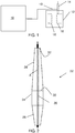
- Fig. 1 schematically shows a detector 10 connected to a bushing 14.
- the detector and bushing together form a bushing arrangement.
- the detector 10 is connected to the bushing via an optical fibre 19.
- the bushing 14 is also attached to a piece of electrical high-voltage equipment.
- the piece of equipment is a transformer 12 provided in a transformer tank filled with an insulating fluid, in the form of transformer oil.
- This transformer 12 has a first and a second winding 16 and 18.
- the bushing 14 is attached to the transformer 12 and as an example to the second winding 18 of the transformer 12. It should here be realized that it may as an alternative be connected to the first winding instead.
- the bushing 14 is according to some variations a condenser core bushing. Therefore, the bushing in fig. 1 comprises a condenser core that surrounds a central conductor.
- the exemplifying condenser core is more particularly a solid condenser core. This also means that it has a surface that faces away from the central conductor 20.
- Fig. 2 schematically shows one type of such condenser core 22 surrounding a conductor 20.
- the condenser core comprises a central section 24 as well as a first and a second peripheral section 26 and 28, where the first and second peripheral sections 26 and 28 are placed on opposite sides of the central section 24.
- the conductor 20 defines a longitudinal axis A through the bushing 14 and the different sections are placed around the conductor 20 along this longitudinal axis A. Thereby the first and second peripheral sections 26 and 28 are placed on opposite sides of the central section 24 along the longitudinal axis A.
- the second peripheral section 28 also has a first end 30 connecting to or being joined to the central section 24 and a second end 32 defining an end of the bushing. This second end 32 also provides an output of the bushing 14, which is an end via which the conductor 20 leaves or exits the bushing 14.
- the first peripheral and central sections 24 and 26 of the condenser core 22 are typically provided or adapted for being inserted into a piece of high-voltage equipment, such as reactive power equipment like a transformer.
- a transformer it may be inserted in the transformer tank in order to be surrounded by insulating fluid of the tank, such as transformer oil, while the second peripheral section 28 is adapted to project out from the piece of equipment for being surrounded by air.
- the central section 24 has an even cross-section along the longitudinal axis A.
- the cross-sectional area is therefore even or the same along the longitudinal axis A.
- the area may be circular and in this case the radius is the same along the longitudinal axis.
- the first and second peripheral sections 26 and 28 have cross-sections that diminish along the longitudinal axis in a direction away from the central section 24. They thus have tapering cross-sections along the longitudinal axis away from the central section. These two sections 26 and 28 thus have cross-sectional areas that grow smaller away from the central section 24 along the longitudinal axis. They thus have diminishing radii.
- the cross-sections discussed above are all taken at right angles to the longitudinal axis A. It should here be realized that it is possible with other shapes of the sections.
- the first and/or the second peripheral section may for instance be cylindrical. Such a cylindrical peripheral section may then also have a cross-section that is the same as or different from the cross-section of the central section. It is also possible that the cross-section of the central section varies. Parts of it may for instance have lower diameters than the rest, for instance for the purpose of mounting to the flange.
- the condenser core 22 typically comprises insulation made of paper and between these papers there is provided foils of electrically conducting material, such as metal, for voltage control purposes. These foils and insulation encircle the conductor 20.
- the paper may be cellulose or synthetic, such as thermoplastic.
- the condenser core may further be solidified using a resin, such as an epoxy resin.
- Fig. 3 shows some more details of the bushing 14, with an optical fibre being placed in a first way in the bushing 14.
- the main conductor 20 is radially surrounded by a number of foils F1, F2, F3, F4, F5, F6, F7 and F8 of electrically conducting material, which are the above-mentioned foils in the interior of the condenser core.
- F1, F2, F3, F4, F5, F6, F7 and F8 of electrically conducting material which are the above-mentioned foils in the interior of the condenser core.
- a first innermost foil F1 which surrounds the main conductor 20.
- a second foil F2 in turn surrounds the first foil F1.
- a fourth foil F4 surrounds the third foil F3.
- a fifth foil F5 surrounds the fourth foil F4
- a sixth foil F6 surrounds the fifth foil F5
- a seventh foil F7 surrounds the sixth foil F6
- an eighth outermost foil F8 surrounds the seventh foil F7. It should also be realized that the number of foils shown is merely an example.
- the foils are more particularly being wound around and coaxial with the central conductor 20.
- the foils are also spaced from each other in a direction that is perpendicular to the longitudinal axis A of the conductor 20. This direction that is perpendicular to the longitudinal axis A is in this embodiment a radial direction.
- Each foil which as an example may be an aluminum or copper foil, is as an example formed as a hollow cylinder, with each foil having an increased diameter in relation to the previous foil closer to the main conductor 20 in the radial direction.
- a foil that is closer than a neighboring foil to the main conductor 20 in the radial direction furthermore has a longer extension along the longitudinal axis A than this neighboring foil.
- the diameter and length may be selected so that each foil should cover the same area.
- the lengths of the foils along the longitudinal axis A decrease with the distance, here radial, to this axis A. It can thus be seen that the foil length of any outer foil is lower than any inner foil that it surrounds or put differently, the foil length in the longitudinal direction of any foil on a radial distance from the conductor is shorter than the foil length of any neighboring foil on a lower radial distance from the conductor.
- the central section 24 is also connected to a flange 34 for grounding purposes. It can also be seen that the second peripheral section 28 is surrounded by a solid isolator 36, which may be ceramic. There may here be a gap between the second peripheral section 28 of the condenser core 22 and the solid isolator 36 and this gap may be filled with fluid insulation.
- the optical fibre 19 is also provided in the bushing 14.
- the optical fibre comprises a first part P1 that is placed in the condenser core 22 and that stretches through the central section 24 of the condenser core 22. The first part is thus placed in the interior of the solid condenser core.
- the fibre also comprises a second part provided adjacent the surface of the second peripheral section 28.
- the second part comprises at least one first straight segment stretching along and in parallel with the condenser core surface between the first and second ends 30, 32 of the second peripheral section 28.
- the second part comprises a first and a second such segment P2A, P2B.
- first segment P2A starts at the first end 30 of the second peripheral section 28, stretches a length along the condenser core surface of the second peripheral section 28 and is joined with the second straight segment P2B that returns back to the first end 30 of the second peripheral section 28 along the condenser core surface. It can also be seen that both segments are placed in the gap between the solid condenser core and the solid isolator 36. They may thereby also be surrounded by the fluid insulation in this gap.
- the first part P1 of the fibre comprises a number of turns of fibre wound around the central conductor 20 between different foils F1, F2, F3, F4, F5, F6, F7 and F8 of the central section 24,
- the first part P1, which in this case may actually start in the first peripheral section 26, is more particularly shaped as a funnel where the radial distance of the turns increase from adjacent a first end of the first part P1 in a first area of the condenser core 22 where the central section 24 joins the first peripheral section 26 towards a second end of the first part P1 in a second area of the condenser core 22 where the central section 24 joins the second peripheral section 28, which is at the first end 30 of the second peripheral section 28.
- each turn encircles an area that is angled in relation to the longitudinal axis A of the conductor 20 so that one point of a turn is closest to the second peripheral section and an opposite point of the same turn is closest to the first peripheral section.
- the normal of such an area defined or encircled by a turn may thus be offset from the longitudinal axis A by an angle. All the turns may furthermore be angled with the same angle to the longitudinal axis A.
- the optical fibre also exits the condenser core at the flange 34.
- the first segment P2A of the second part of the fibre is here joined to the end of the first part P1 of the fibre that has the highest turn radius, which is where the central section 24 joins the second peripheral section 28.
- the second segment P2B is in turn joined to the part of the fibre that exits the bushing at the flange 34.
- the optical fibre is adapted to detect physical properties of the bushing condenser core that are influenced or caused by its operation. These detected physical properties are indicative of the health of the bushing.
- the properties may furthermore be the properties of the condensers core, in which case they may also be indicative of condenser core health.
- an optical fibre is introduced inside and on the outer surface of the condenser core 22 in an electric field to measure physical properties of the condenser core influenced or caused by the use of the bushing. These physical properties are measured directly in the solid material of the condenser core, which material may be epoxy or thermoplastics. Physical properties caused and/or changed by the influences, such as temperature and electrical field strength, will thus be obtained directly from inside he the insulation material of the condenser core and optionally also from the condenser core surface.
- the capacitive condenser core It is in this way possible to measure online the status and health of the capacitive condenser core and thereby also of the bushing. It is for instance possible to detect hot spots of the solid condenser core, i.e. areas where the temperature is significantly higher than in other parts of the condenser core. It is more particularly possible to measure the deviation of real time temperature in C° at a hot spot inside the solid insulation material as the bushing is being used. It is also possible to detect real time electrical stress kV/mm inside the solid insulation material at the most stressed area of the condenser core, which is typically between edges of neighboring foils. In this regard the first part of the fibre may contribute more to the hot spot measurements, while the second part may contribute more to the electrical stress measurements.
- the fact that the fibre is wound inside the condenser core in between the foil inserts may simplify detecting the temperature deviation of the hot spots and possibly also voltage stress. Thereby it is possible to obtain earlier warnings than if a deviation in capacitance and tan d measurements are being made since such deviations have already occurred after breakdown. It is also possible to measure transient stresses inside the condenser core and if the equipment is a part of an electrical grid, to give information to the grid operator, about the health of the bushing. It is also possible to conduct diagnostic on a bushing prepared with the sensors in real time in service.
- the bushing arrangement therefore detects physical properties of the condenser core being caused or influenced by the operation of the bushing, which properties comprise condenser core temperature and/or electrical field strength, which electrical field strength measurements may be used to determine the electrical field stress between foil edges.
- the detector may comprise an opto/electrical transducer for converting an optical signal into the electrical domain and vice versa. It may also comprise circuitry for generating light pulses and for evaluating returned light.t may also comprise sampling circuitry.
- the evaluating circuitry may be implemented using software running on a processor.
- the detector is capable of detecting high electrical fields. It can also detect overvoltages coming from transients, very fast transient or harmonics, such as in High Voltage Direct Current (HVDC) applications. Thereby, it is possible to measure high electrical fields and to collect the information and in the long term identify ageing or overstress of the insulation material.
- HVDC High Voltage Direct Current
- An unhealthy bushing may thus indicate a defect or a problem in the environment in which the bushing is placed. It may as an example be indicative of a leakage in the previously disclosed tank. It may also or alternatively be indicative of imbalances in an electrical grid to which the piece of high voltage equipment is connected.
- the temperature and voltage stress experienced by the foil edges are measured on the oil side of the bushing, which oil side is typically made up of the central and first peripheral sections 24 and 26 of the condenser core.
- Fig. 4 shows a realization with the optical fibre being placed in a second way in the bushing. This realization is suitable for measuring the temperature of the bushing along the conductor together with detecting the electrical field stress on the air side of the bushing 14, which air side is typically made up of the second peripheral section 20.
- the first part P1 of the fibre is only placed in the central section 24. It more particularly comprises turns having the same radius and being placed between the innermost foil F1 and the conductor 20. There is also a third part P3 of the fibre in the first peripheral section 26 with turns having the same radius and being placed between the innermost foil F1 and the conductor 20 as well as a fourth part P4 in the second peripheral section 28 with turns having the same radius and being placed between the innermost foil F1 and the conductor 20.
- the radius of the turns of the first, third and fourth parts P1, P3, P4 of the fibre is here the same for all parts. These turns are also all angled to the longitudinal axis A, which may be an angling in the same way and using the same angle as in fig. 3 .
- the third part P3 is in this case connected to or joined with the first part P1, which in turn is connected to or joined with the fourth part P4, which exits the condenser core 22, but not the bushing 14, at the second end 32.
- a first straight segment P2A of the second part is connected to the end of the fourth part P4 exiting the condenser core 22.
- the first straight segment P2A then stretches all the way between the first and second ends 30, 32 of the second peripheral section 28.
- the first segment P2A thus starts at the second end 32 of the second peripheral section 28 and then ends at the first end 30, where it is connected to the part of the fibre that again exits the bushing via the flange 34 at the central section 24.
- the fibre comprises the first part P1 having the same type of realization as in fig. 4 .
- the first part P1 is connected to the fibre part that exits the bushing at the flange 34.
- the first part thus ends before the second peripheral section 28 is reached.
- the previously described third part P3 with an even turns radius in the first peripheral section 26 and being connected to the first part.
- All turns may also here be angled to the longitudinal axis A in the same way and using the same angle as in fig. 3 .
- the connectivity problem is addressed through providing an enclosure for the part of the fibre that is to be connected to the detector.
- Such an enclosure may be provided in the condenser core at the flange.
- the enclosure may surround a length of the fibre that is to be drawn out of the condenser core for connection to the detector via the flange.
- the enclosure may comprise an interior volume having an inner surface, which inner surface has at least one point at a maximum radial distance from the longitudinal axis.
- the volume may also comprise a distancing element keeping the length of fibre at a pre-determined distance from the above-mentioned point on the inner surface.
- the enclosure may comprise a first and second chamber, where the first chamber comprises the length of fibre that is to be used for interconnection with the detector and the second chamber is an auxiliary chamber that is essentially empty.
- the second chamber is also radially further away from the longitudinal axis than the first chamber. Put differently, the whole of the first chamber is closer to the longitudinal axis than the second chamber.
- the distancing element may be a wall separating the first chamber from the second chamber and the inner surface may be an inner surface of the second chamber.
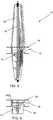
- Fig. 6 schematically shows the central section 24 of the condenser core from fig. 5 , but where the length of the fibre provided for interconnection is enclosed by a first type of enclosure in the form of a hose 40A in the condenser core, such as a Silicone hose, that protects the fibre.
- the hose 40A is embedded in the condenser core just underneath its surface and stretches around the longitudinal axis, for instance radially.
- Fig. 7 schematically shows how the hose 40A is placed inside the condenser core and its two chambers; a first chamber 44A comprising the fibre 19 and a second auxiliary chamber 1A that is empty, where the first chamber 44A is separated from the second chamber 46A by a central wall 42A, which thus forms the distancing element.
- the inner surface having a point P at a maximum radial distance to the longitudinal axis is an inner surface 41A of the second chamber 46A.
- the pre-determined distance D of the distancing element 42A to this point P is shown.
- the hose 40A is initially totally buried inside the condenser core adjacent the surface.
- material is removed from the condenser core surface and perhaps only from the central section of the condenser core surface in a final material removal step.
- This material removal which may be made in a radial direction towards the longitudinal axis, may involve cutting away material from the surface, for instance using knives. This material removal is carried out until the hose 40A is located. Material removal is thus ended as soon as the hose 40A has been discovered.
- the pre-determined distance D may also correspond to a maximum allowed material removal depth.
- the first chamber 44A can in one end be sealed using a unidirectional valve 48 and sealed with a tight seal 50 in an opposite end, which ends forms a fluid exhaust area and a fibre entry area of the first chamber 44A.
- the unidirectional valve 48 is unidirectional in that it allows a unidirectional flow of fluid, such as air, from within the chamber 44A to the outside but stops fluid, such as epoxy, from flowing into it.
- the unidirectional valve 48 may be realized in a number of different ways where one is in the form of a Presta valve.
- the hose 40A may have different types of cross-sectional areas. It may for instance be elliptic, such as circular, or it may be rectangular, such as square.
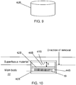
- Fig. 9 and 10 shows a second type of protective enclosure, in the form of a box 40B, which box may be cylindrical in shape.
- the box 40B may also be made of Silicone.
- This box 40B may be provided in a limited size area of the central section of the condenser core close to the outer surface of the core, such as in a sector of the central section of the condenser core, and buried just underneath the surface.
- the box 40B may have a first and a second chamber 44B and 46B separated by a wall 42B, where again the second chamber 46B is radially further away from the longitudinal axis than the first chamber 44B. In this case a number of turns of fibre 19 may be placed in the first chamber 44B.
- the wall 42B forms the distancing element distancing the length of fibre a pre-determined distance D from an inner surface 41B of the second chamber 46B, which inner surface has at least one point at a maximum radial distance from the longitudinal axis.
- the fibre 19 in the box 40B is accessed in the same way, through removing material from the condenser core surface in a radial direction towards the longitudinal axis until the box 40B is located. Any removal of material from the outer box wall will then be from the wall of the second chamber 46B that is empty. After the box 40B has been discovered the fibre windings may be drawn out from the first chamber 44B and connected to the detector via the flange.
- first chamber of the second type of enclosure may have a fibre entry area that has a tight seal and a gas exhaust area sealed with a unidirectional valve.
- the distancing element may be a disc or plate, placed between the inner surface of the interior volume and the length of fibre.
- the disc may as an example be a plastic disc. Material removal will then involve removing disc material, but not any fibre.
- the present invention can be varied in a multitude of ways. It is for instance possible that the bushing is a gas-filled bushing instead of a condenser core bushing.
Landscapes
- Physics & Mathematics (AREA)
- General Physics & Mathematics (AREA)
- Engineering & Computer Science (AREA)
- Electromagnetism (AREA)
- Power Engineering (AREA)
- Chemical & Material Sciences (AREA)
- Ceramic Engineering (AREA)
- Insulators (AREA)
- Measuring Instrument Details And Bridges, And Automatic Balancing Devices (AREA)
Abstract
Description
- The present invention generally relates to high voltage equipment. More particularly the present invention relates to a bushing for high voltage applications as well as to a bushing arrangement comprising such a bushing.
- The health and status of bushings for instance a condenser core of a bushing is important in many power systems such as for detecting ageing and degrading of insulation material used in the bushing.
- Such health and status is typically determined through offline or online measurements of the change in capacitance and change in tan d. Ageing or degrading of solid insulation is traditionally determined by measuring capacitance or losses (tan d) with online or offline measuring equipment. In this case either a capacitance deviation occurring after break down between the foil insert is detected or an increase in losses (moisture content) using tan d is detected. Increased losses will increase the heat and continue to escalate until there is a thermal runaway.
- As the health and status of a bushing is important, it is therefore of interest to improve the determination. Two properties that may be of interest in such improvement are the temperature variations of the insulation and the electrical field stresses experienced by foils of the condenser core.
- Temperature measurements have been known to be made in bushings, especially with regard to the central conductor that the condenser core surrounds.
-
WO 2017/152985 describes one bushing where such a central conductor temperature is measured. According to the document an optical waveguide is placed on and along a conductor of such a bushing for measuring the conductor temperature. The waveguide can also be placed in a solid insulating member in one surrounding insulating layer or in a surrounding metal foil, for instance at a distance of less than 2 centimeters from the central conductor. The optical waveguide may also be placed in additional insulation that is gaseous, porous or foam-like surrounding the solid body. - It would in view of what is disclosed above be of interest to obtain a bushing that is better adapted to measuring physical properties of the bushing in order to improve on the health determination of the bushing, which physical properties are properties being influenced or caused by the operation of the bushing. Examples of these physical properties are temperature and experienced electrical field strengths.
- One object of the present invention is to provide a bushing that addresses the problem of improving the health determination of the bushing.
- This object is according to a first aspect obtained through a bushing for high voltage applications comprising a conductor defining a longitudinal axis through the bushing,
the bushing having a central section and a first and a second peripheral section on opposite sides of the central section along the longitudinal axis, and comprising an optical fibre with a first part stretching through the central section, the fibre being adapted to detect physical properties influenced or caused by the operation of the bushing. - In this way the first part of the optical fibre may be placed inside the bushing.
- It is furthermore possible that the physical properties are properties indicative of the health of the bushing. The physical properties may furthermore comprise temperature and/or electrical field strength.
- The object is according to a second aspect achieved through a bushing arrangement comprising the bushing according to the first aspect and at least one detector configured to detect physical properties of the bushing influenced or caused by the operation of the bushing.
- The bushing may furthermore comprise a condenser core that surrounds the conductor. In this case the sections may furthermore be sections of the condenser core. The condenser core may furthermore be a solid condenser core. Additionally the optical fibre may be placed inside the condenser core.
- In this case the physical properties being detected may be physical properties of the condenser core that are influenced or caused by the operation of the bushing, which physical properties are properties indicative of the condenser core health. The physical properties may furthermore comprise condenser core temperature and/or electrical field strength.
- In a variation of the first and second aspects, the first peripheral and central sections are adapted to be inserted into a piece of high-voltage equipment for being surrounded by insulating fluid and the second peripheral section is adapted to project out from the piece of equipment for being surrounded by air.
- In another variation of the first and second aspects, the fibre exits the bushing via a flange surrounding the central section, which flange may be grounded.
- In a further variation of the first and second aspects where the bushing comprises a solid condenser core, there is an enclosure for a length of fibre that is to exit the bushing, which enclosure is buried in the central section adjacent the condenser core surface. The enclosure comprises an interior volume having an inner surface comprising at least one point at a maximum radial distance from the longitudinal axis. The enclosure also comprises a distancing element keeping the length of fibre at a pre-determined distance from the above-mentioned point.
- The interior volume of the enclosure may comprise a first chamber for the length of fibre as well as a second auxiliary chamber, where the second chamber is radially further away from the longitudinal axis than the first chamber. In this case the distancing element may be a wall separating the first chamber from the second chamber and the inner surface may be an inner surface of the second chamber.
- The first chamber may have a fibre entry area having a tight seal around the fibre and a fluid exhaust area that is sealed with a unidirectional valve.
- The enclosure may be formed as a hose or as a box.
- In the case of a box, it is also possible to omit the use of chambers. Instead the distancing element may alternatively be a disc or plate, placed between the inner surface of the interior volume and the length of fibre.
In another variation of the first and second aspects where the bushing comprises a solid condenser core, the second peripheral section comprises a first end joined to the central section and a second end defining an end of the bushing through which the central conductor exits and the fibre comprises a second part with at least one first straight segment stretching outside of the condenser core along the condenser core surface between the first and second ends of the second peripheral section. - It is possible that the second peripheral section is surrounded by a solid isolator, in which case the second part of the fibre stretches in a gap between the condenser core and the solid isolator, where the gap may be filled with fluid insulation
- The first straight segment may stretch all the way between the first and second ends of the second peripheral section. Alternatively, it may start at the first end of the second peripheral section, stretch a length along the condenser core surface and be joined with a second straight segment that returns back to the first end of the second peripheral section.
- In another variation of the first and second aspects, the condenser core comprises a number of foils of conductive material, wound around and coaxial with the conductor, where the length in the longitudinal direction of any foil on a radial distance from the conductor is shorter than the foil length of any neighboring foil on a lower radial distance from the conductor.
- The cross-sectional area of the central section may be even. It is additionally possible that the cross-sectional areas of the first and second peripheral sections decrease along the longitudinal axis away from the central section for adapting the size of the section to the varying lengths of the foils.
- In a further variation of the first and second aspects, the first part of the fibre comprises a number of turns of fibre wound around the central conductor between different foils of the central section.
- When the turns are being wound around different foils of the central section inside a condenser core, it is also possible that the radial distance of the turns increase from a first end of the first part in a first area where the central section joins the first peripheral section towards a second end of the first part in a second area where the central section joins the second peripheral section. It is here also possible that the first part is wound so that it has a funnel shape. It is moreover possible that the first part stretches from being placed between an innermost foil and the conductor to being placed between an outermost foil and the condenser core surface.
- In yet another variation of the first and second aspects, each turn encircles an area that is angled in relation to the longitudinal axis of the conductor so that one point of a turn is closest to the second peripheral section and an opposite point of the same turn is closest to the first peripheral section.
- In another variation the first part of the fibre comprises turns having the same radius and being placed between the innermost foil and the conductor.
- In yet another variation the fibre comprises a third part in the first peripheral section joined with the first part, where the third part has turns with the same radius and is placed between the innermost foil and the conductor.
- In still another variation the fibre comprises a fourth part in the second peripheral section joined with the first part, where the fourth part has turns with the same radius and is placed between the innermost foil and the conductor.
- The present invention has a number of advantages. It allows the health of the bushing such as the health of the condenser core to be determined in a good way before failure. This health determination can also be used in diagnosing defects in the environment of the bushing.
- The present invention will in the following be described with reference being made to the accompanying drawings, where
-
fig. 1 schematically shows a detector being connected to a bushing, which in turn is attached to a transformer, -
fig. 2 schematically shows a condenser core with a central as well as a first and second peripheral section, all surrounding a central conductor, -
fig.3 schematically shows the bushing comprising the condenser core, a flange, outer isolation on the second peripheral section as well as an optical fibre placed in a first way in the bushing, -
fig.4 schematically shows the bushing with the condenser core, flange, outer isolation and optical fibre placed in a second way in the bushing, and -
fig. 5 schematically shows the bushing with the condenser core, flange, outer isolation and optical fibre placed in a third way in the bushing, -
fig. 6 schematically shows the central section of the condenser core where a first type of protective enclosure surrounds the last part of the fibre before it enters the flange, -
fig. 7 schematically shows a cross-section through the first type of protective enclosure together with different levels of condenser core material before and after a final material removal step, -
fig. 8 schematically shows a cut through the first type of enclosure along parts of its length, -
fig. 9 schematically shows a second type of protective enclosure, and -
fig. 10 schematically shows a cross-section through the second type of enclosure together with different levels of condenser core material before and after a final material removal step. - The present invention concerns a bushing for use in high voltage applications, such as high voltage power transmission systems as well as a bushing arrangement comprising a bushing and a detector. A bushing may as an example be provided for use in high voltage equipment, such as reactive high voltage equipment, like transformers.
- Embodiments of the invention are discussed in detail below. In describing embodiments, specific terminology is employed for the sake of clarity. However, the invention is not intended to be limited to the specific terminology so selected. While specific exemplary embodiments are discussed, it should be understood that this is done for illustration purposes only. A person skilled in the relevant art will recognize that other components and configurations can be used without parting from the spirit and scope of the invention.
- A bushing is a type of apparatus that may be used for measuring electrical properties such as voltages of pieces electrical high-voltage equipment, for instance reactive high-voltage equipment. Examples of equipment include conductors, power lines, cable terminations, inductively operating elements such as reactors and transformers, for instance instrument transformers, and capacitive elements such as capacitors and capacitive voltage dividers. A bushing may also be provided for a dead tank breaker. A high voltage may in this regard be a voltage of around or above 100 kV.
- In order to provide correct measurement results, which are vital for the control and safety in high-voltage applications, there is a need for the bushing to function properly. The functioning of it does therefore often have to be diagnosed, i.e. the health of the bushing has to be determined. The present invention is directed towards providing such diagnosis. This type of diagnosis may be provided for determining the health of the bushing, such as to determine ageing and predicting when it may fail. Such diagnosis may also be of interest for assessing the environment of the bushing.
-
Fig. 1 schematically shows adetector 10 connected to abushing 14. The detector and bushing together form a bushing arrangement. Thedetector 10 is connected to the bushing via anoptical fibre 19. Thebushing 14 is also attached to a piece of electrical high-voltage equipment. In the example depicted infig. 1 , the piece of equipment is atransformer 12 provided in a transformer tank filled with an insulating fluid, in the form of transformer oil. Thistransformer 12 has a first and a second winding 16 and 18. Thebushing 14 is attached to thetransformer 12 and as an example to the second winding 18 of thetransformer 12. It should here be realized that it may as an alternative be connected to the first winding instead. - The
bushing 14 is according to some variations a condenser core bushing. Therefore, the bushing infig. 1 comprises a condenser core that surrounds a central conductor. The exemplifying condenser core is more particularly a solid condenser core. This also means that it has a surface that faces away from thecentral conductor 20. -
Fig. 2 schematically shows one type ofsuch condenser core 22 surrounding aconductor 20. The condenser core comprises acentral section 24 as well as a first and a secondperipheral section peripheral sections central section 24. Theconductor 20 defines a longitudinal axis A through thebushing 14 and the different sections are placed around theconductor 20 along this longitudinal axis A. Thereby the first and secondperipheral sections central section 24 along the longitudinal axis A. The secondperipheral section 28 also has afirst end 30 connecting to or being joined to thecentral section 24 and asecond end 32 defining an end of the bushing. Thissecond end 32 also provides an output of thebushing 14, which is an end via which theconductor 20 leaves or exits thebushing 14. - The first peripheral and
central sections condenser core 22 are typically provided or adapted for being inserted into a piece of high-voltage equipment, such as reactive power equipment like a transformer. In the case of a transformer, it may be inserted in the transformer tank in order to be surrounded by insulating fluid of the tank, such as transformer oil, while the secondperipheral section 28 is adapted to project out from the piece of equipment for being surrounded by air. - It can be seen that in the example given in the figures, the
central section 24 has an even cross-section along the longitudinal axis A. The cross-sectional area is therefore even or the same along the longitudinal axis A. The area may be circular and in this case the radius is the same along the longitudinal axis. It can also be seen that the first and secondperipheral sections central section 24. They thus have tapering cross-sections along the longitudinal axis away from the central section. These twosections central section 24 along the longitudinal axis. They thus have diminishing radii. This is done in order to adapt the size of these sections to varying lengths of foils described below. The cross-sections discussed above are all taken at right angles to the longitudinal axis A. It should here be realized that it is possible with other shapes of the sections. The first and/or the second peripheral section may for instance be cylindrical. Such a cylindrical peripheral section may then also have a cross-section that is the same as or different from the cross-section of the central section. It is also possible that the cross-section of the central section varies. Parts of it may for instance have lower diameters than the rest, for instance for the purpose of mounting to the flange. - The
condenser core 22 typically comprises insulation made of paper and between these papers there is provided foils of electrically conducting material, such as metal, for voltage control purposes. These foils and insulation encircle theconductor 20. The paper may be cellulose or synthetic, such as thermoplastic. The condenser core may further be solidified using a resin, such as an epoxy resin. -
Fig. 3 shows some more details of thebushing 14, with an optical fibre being placed in a first way in thebushing 14. As can be seen themain conductor 20 is radially surrounded by a number of foils F1, F2, F3, F4, F5, F6, F7 and F8 of electrically conducting material, which are the above-mentioned foils in the interior of the condenser core. In thisbushing 14 there is thus a first innermost foil F1, which surrounds themain conductor 20. A second foil F2 in turn surrounds the first foil F1. Thereafter follows a third foil F3 that surrounds the second foil F2. A fourth foil F4 surrounds the third foil F3. A fifth foil F5 surrounds the fourth foil F4, a sixth foil F6 surrounds the fifth foil F5, a seventh foil F7 surrounds the sixth foil F6 and finally an eighth outermost foil F8 surrounds the seventh foil F7. It should also be realized that the number of foils shown is merely an example. - The foils are more particularly being wound around and coaxial with the
central conductor 20. The foils are also spaced from each other in a direction that is perpendicular to the longitudinal axis A of theconductor 20. This direction that is perpendicular to the longitudinal axis A is in this embodiment a radial direction. Each foil, which as an example may be an aluminum or copper foil, is as an example formed as a hollow cylinder, with each foil having an increased diameter in relation to the previous foil closer to themain conductor 20 in the radial direction. A foil that is closer than a neighboring foil to themain conductor 20 in the radial direction furthermore has a longer extension along the longitudinal axis A than this neighboring foil. The diameter and length may be selected so that each foil should cover the same area. Therefore, the lengths of the foils along the longitudinal axis A decrease with the distance, here radial, to this axis A. It can thus be seen that the foil length of any outer foil is lower than any inner foil that it surrounds or put differently, the foil length in the longitudinal direction of any foil on a radial distance from the conductor is shorter than the foil length of any neighboring foil on a lower radial distance from the conductor. - The
central section 24 is also connected to aflange 34 for grounding purposes. It can also be seen that the secondperipheral section 28 is surrounded by asolid isolator 36, which may be ceramic. There may here be a gap between the secondperipheral section 28 of thecondenser core 22 and thesolid isolator 36 and this gap may be filled with fluid insulation. - As can be seen in
fig. 3 theoptical fibre 19 is also provided in thebushing 14. The optical fibre comprises a first part P1 that is placed in thecondenser core 22 and that stretches through thecentral section 24 of thecondenser core 22. The first part is thus placed in the interior of the solid condenser core. In the variation of the bushing shown infig. 3 , the fibre also comprises a second part provided adjacent the surface of the secondperipheral section 28. The second part comprises at least one first straight segment stretching along and in parallel with the condenser core surface between the first and second ends 30, 32 of the secondperipheral section 28. In the variation offig. 3 the second part comprises a first and a second such segment P2A, P2B. It can be seen that the first segment P2A starts at thefirst end 30 of the secondperipheral section 28, stretches a length along the condenser core surface of the secondperipheral section 28 and is joined with the second straight segment P2B that returns back to thefirst end 30 of the secondperipheral section 28 along the condenser core surface. It can also be seen that both segments are placed in the gap between the solid condenser core and thesolid isolator 36. They may thereby also be surrounded by the fluid insulation in this gap. - As can also be seen in
fig. 3 , the first part P1 of the fibre comprises a number of turns of fibre wound around thecentral conductor 20 between different foils F1, F2, F3, F4, F5, F6, F7 and F8 of thecentral section 24, The first part P1, which in this case may actually start in the firstperipheral section 26, is more particularly shaped as a funnel where the radial distance of the turns increase from adjacent a first end of the first part P1 in a first area of thecondenser core 22 where thecentral section 24 joins the firstperipheral section 26 towards a second end of the first part P1 in a second area of thecondenser core 22 where thecentral section 24 joins the secondperipheral section 28, which is at thefirst end 30 of the secondperipheral section 28. Thereby the fibre is wound between different foils in the central section and optionally also in a part of the firstperipheral section 26 in such a way that the turns stretch from being placed between an innermost foil F1 of thecondenser core 22 and theconductor 20 to being placed between an outermost foil F8 and the condenser core surface, i.e. to being placed inside thesolid condenser core 22 between the outermost foil and the outer surface of thecondenser core 22. Moreover, each turn encircles an area that is angled in relation to the longitudinal axis A of theconductor 20 so that one point of a turn is closest to the second peripheral section and an opposite point of the same turn is closest to the first peripheral section. The normal of such an area defined or encircled by a turn may thus be offset from the longitudinal axis A by an angle. All the turns may furthermore be angled with the same angle to the longitudinal axis A. - The optical fibre also exits the condenser core at the
flange 34. The first segment P2A of the second part of the fibre is here joined to the end of the first part P1 of the fibre that has the highest turn radius, which is where thecentral section 24 joins the secondperipheral section 28. The second segment P2B is in turn joined to the part of the fibre that exits the bushing at theflange 34. - The optical fibre is adapted to detect physical properties of the bushing condenser core that are influenced or caused by its operation. These detected physical properties are indicative of the health of the bushing. The properties may furthermore be the properties of the condensers core, in which case they may also be indicative of condenser core health.
- It can be seen that an optical fibre is introduced inside and on the outer surface of the
condenser core 22 in an electric field to measure physical properties of the condenser core influenced or caused by the use of the bushing. These physical properties are measured directly in the solid material of the condenser core, which material may be epoxy or thermoplastics. Physical properties caused and/or changed by the influences, such as temperature and electrical field strength, will thus be obtained directly from inside he the insulation material of the condenser core and optionally also from the condenser core surface. - It is in this way possible to measure online the status and health of the capacitive condenser core and thereby also of the bushing. It is for instance possible to detect hot spots of the solid condenser core, i.e. areas where the temperature is significantly higher than in other parts of the condenser core. It is more particularly possible to measure the deviation of real time temperature in C° at a hot spot inside the solid insulation material as the bushing is being used. It is also possible to detect real time electrical stress kV/mm inside the solid insulation material at the most stressed area of the condenser core, which is typically between edges of neighboring foils. In this regard the first part of the fibre may contribute more to the hot spot measurements, while the second part may contribute more to the electrical stress measurements. The fact that the fibre is wound inside the condenser core in between the foil inserts may simplify detecting the temperature deviation of the hot spots and possibly also voltage stress. Thereby it is possible to obtain earlier warnings than if a deviation in capacitance and tan d measurements are being made since such deviations have already occurred after breakdown. It is also possible to measure transient stresses inside the condenser core and if the equipment is a part of an electrical grid, to give information to the grid operator, about the health of the bushing. It is also possible to conduct diagnostic on a bushing prepared with the sensors in real time in service.
- The bushing arrangement therefore detects physical properties of the condenser core being caused or influenced by the operation of the bushing, which properties comprise condenser core temperature and/or electrical field strength, which electrical field strength measurements may be used to determine the electrical field stress between foil edges.
- The detector may comprise an opto/electrical transducer for converting an optical signal into the electrical domain and vice versa. It may also comprise circuitry for generating light pulses and for evaluating returned light.t may also comprise sampling circuitry. The evaluating circuitry may be implemented using software running on a processor.
- Through the bushing realization, the detector is capable of detecting high electrical fields. It can also detect overvoltages coming from transients, very fast transient or harmonics, such as in High Voltage Direct Current (HVDC) applications. Thereby, it is possible to measure high electrical fields and to collect the information and in the long term identify ageing or overstress of the insulation material.
- Depending on the frequency and/or speed of the sampling circuitry it is possible to provide a lower sampling possibility to only give warnings, not tripping, or to provide more advanced sampling equipment used to detect overvoltages or to perform failure investigations on bushings. This is possible if a bushing is prepared with optic sensors that can replace a failed bushing in a transformer. If such a prepared bushing is connected to the more advanced sampling equipment, it may then be possible to perform investigations in service mode with full voltage on.
- When the temperature and the electrical stresses that the insulation material is exposed to are monitored, it is possible to improve on the determination of the lifetime of the bushing, which is of advantage in maintenance situations and for diagnosing defects in the environment in which the bushing is provided.
- An unhealthy bushing may thus indicate a defect or a problem in the environment in which the bushing is placed. It may as an example be indicative of a leakage in the previously disclosed tank. It may also or alternatively be indicative of imbalances in an electrical grid to which the piece of high voltage equipment is connected.
- In the variation shown in
fig.3 the temperature and voltage stress experienced by the foil edges are measured on the oil side of the bushing, which oil side is typically made up of the central and firstperipheral sections -
Fig. 4 shows a realization with the optical fibre being placed in a second way in the bushing. This realization is suitable for measuring the temperature of the bushing along the conductor together with detecting the electrical field stress on the air side of thebushing 14, which air side is typically made up of the secondperipheral section 20. - As can be seen in
fig. 4 , the first part P1 of the fibre is only placed in thecentral section 24. It more particularly comprises turns having the same radius and being placed between the innermost foil F1 and theconductor 20. There is also a third part P3 of the fibre in the firstperipheral section 26 with turns having the same radius and being placed between the innermost foil F1 and theconductor 20 as well as a fourth part P4 in the secondperipheral section 28 with turns having the same radius and being placed between the innermost foil F1 and theconductor 20. The radius of the turns of the first, third and fourth parts P1, P3, P4 of the fibre is here the same for all parts. These turns are also all angled to the longitudinal axis A, which may be an angling in the same way and using the same angle as infig. 3 . - The third part P3 is in this case connected to or joined with the first part P1, which in turn is connected to or joined with the fourth part P4, which exits the
condenser core 22, but not thebushing 14, at thesecond end 32. A first straight segment P2A of the second part is connected to the end of the fourth part P4 exiting thecondenser core 22. - The first straight segment P2A then stretches all the way between the first and second ends 30, 32 of the second
peripheral section 28. The first segment P2A thus starts at thesecond end 32 of the secondperipheral section 28 and then ends at thefirst end 30, where it is connected to the part of the fibre that again exits the bushing via theflange 34 at thecentral section 24. - Another realization with the optical fibre placed in a third way is the bushing shown in
fig. 5 . This realization is suitable for measuring the condenser core temperature on the oil side of the bushing. - In this case the fibre comprises the first part P1 having the same type of realization as in
fig. 4 . However, it can be seen that the fibre does not reach all the way up to thefirst end 30 of the secondperipheral section 28. Instead the first part P1 is connected to the fibre part that exits the bushing at theflange 34. The first part thus ends before the secondperipheral section 28 is reached. It can be seen that there is also here the previously described third part P3 with an even turns radius in the firstperipheral section 26 and being connected to the first part. There is also no second part. All turns may also here be angled to the longitudinal axis A in the same way and using the same angle as infig. 3 . - It should be realized that it is possible to also add a second part of the fibre to the bushing in
fig. 5 , in the same way as is shown infig. 3 . It is also instead or additionally possible to add a fourth part to the bushing infig. 5 , in which case the fourth and second parts may be realized in the way shown infig. 4 , i.e. with the fourth part connected to the first part at the area where the central section joins the second peripheral section and the second part stretches along the condenser core surface between the second end of the second peripheral section and the flange at the central section. Alternatively it is possible to have also the fourth part of the second peripheral section shaped as a funnel and being wound around the central conductor between different foils. This latter variation is also possible to make in the realization shown infig. 4 - It is a bit tricky to produce the bushing due to the fact that the fibre and the condenser core material react differently to the application of heat in the production process. They shrink differently. The fibre is also sensitive to cuts and excessive bending. This may pose problems in the connection of the fibre to the detector. Some variations of the invention address this situation.
- The connectivity problem is addressed through providing an enclosure for the part of the fibre that is to be connected to the detector. Such an enclosure may be provided in the condenser core at the flange. The enclosure may surround a length of the fibre that is to be drawn out of the condenser core for connection to the detector via the flange. The enclosure may comprise an interior volume having an inner surface, which inner surface has at least one point at a maximum radial distance from the longitudinal axis. The volume may also comprise a distancing element keeping the length of fibre at a pre-determined distance from the above-mentioned point on the inner surface.
- The enclosure may comprise a first and second chamber, where the first chamber comprises the length of fibre that is to be used for interconnection with the detector and the second chamber is an auxiliary chamber that is essentially empty. The second chamber is also radially further away from the longitudinal axis than the first chamber. Put differently, the whole of the first chamber is closer to the longitudinal axis than the second chamber. In this case the distancing element may be a wall separating the first chamber from the second chamber and the inner surface may be an inner surface of the second chamber.
-
Fig. 6 schematically shows thecentral section 24 of the condenser core fromfig. 5 , but where the length of the fibre provided for interconnection is enclosed by a first type of enclosure in the form of ahose 40A in the condenser core, such as a Silicone hose, that protects the fibre. Thehose 40A is embedded in the condenser core just underneath its surface and stretches around the longitudinal axis, for instance radially. -
Fig. 7 schematically shows how thehose 40A is placed inside the condenser core and its two chambers; afirst chamber 44A comprising thefibre 19 and a second auxiliary chamber 1A that is empty, where thefirst chamber 44A is separated from thesecond chamber 46A by acentral wall 42A, which thus forms the distancing element. It can also be seen that the inner surface having a point P at a maximum radial distance to the longitudinal axis, is aninner surface 41A of thesecond chamber 46A. In the figure also the pre-determined distance D of thedistancing element 42A to this point P is shown. - As can be seen, the
hose 40A is initially totally buried inside the condenser core adjacent the surface. In order to access thefibre 19 for connection to the detector, material is removed from the condenser core surface and perhaps only from the central section of the condenser core surface in a final material removal step. This material removal, which may be made in a radial direction towards the longitudinal axis, may involve cutting away material from the surface, for instance using knives. This material removal is carried out until thehose 40A is located. Material removal is thus ended as soon as thehose 40A has been discovered. It is then likely that during the removal of material a part of the outer hose wall will be removed, which is then a part of the hose where also the point P of theinner surface 41A that is at the maximum radial distance to the longitudinal axis is provided. However, as the length of fibre is distanced the pre-determined distance D from the above-mentioned point P, the part of the outer wall of the hose that is being removed will be the outer wall of thesecond chamber 46A that is empty. No harm will be made to thefibre 19, as it is placed in thefirst chamber 44A. For this reason the pre-determined distance D may also correspond to a maximum allowed material removal depth. - It is then possible to draw out the length of
fibre 19 from thefirst chamber 44A and connect it to the detector via the flange. - As can be seen in
fig. 8 , thefirst chamber 44A can in one end be sealed using aunidirectional valve 48 and sealed with atight seal 50 in an opposite end, which ends forms a fluid exhaust area and a fibre entry area of thefirst chamber 44A. Theunidirectional valve 48 is unidirectional in that it allows a unidirectional flow of fluid, such as air, from within thechamber 44A to the outside but stops fluid, such as epoxy, from flowing into it. Theunidirectional valve 48 may be realized in a number of different ways where one is in the form of a Presta valve. - The
hose 40A may have different types of cross-sectional areas. It may for instance be elliptic, such as circular, or it may be rectangular, such as square. -
Fig. 9 and 10 shows a second type of protective enclosure, in the form of abox 40B, which box may be cylindrical in shape. Thebox 40B may also be made of Silicone. Thisbox 40B may be provided in a limited size area of the central section of the condenser core close to the outer surface of the core, such as in a sector of the central section of the condenser core, and buried just underneath the surface. Thebox 40B may have a first and asecond chamber wall 42B, where again thesecond chamber 46B is radially further away from the longitudinal axis than thefirst chamber 44B. In this case a number of turns offibre 19 may be placed in thefirst chamber 44B. Also in this case, thewall 42B forms the distancing element distancing the length of fibre a pre-determined distance D from aninner surface 41B of thesecond chamber 46B, which inner surface has at least one point at a maximum radial distance from the longitudinal axis. - The
fibre 19 in thebox 40B is accessed in the same way, through removing material from the condenser core surface in a radial direction towards the longitudinal axis until thebox 40B is located. Any removal of material from the outer box wall will then be from the wall of thesecond chamber 46B that is empty. After thebox 40B has been discovered the fibre windings may be drawn out from thefirst chamber 44B and connected to the detector via the flange. - Naturally also the first chamber of the second type of enclosure may have a fibre entry area that has a tight seal and a gas exhaust area sealed with a unidirectional valve.
- In the case of a box, it is also possible to omit the use of chambers. Instead the distancing element may be a disc or plate, placed between the inner surface of the interior volume and the length of fibre. The disc may as an example be a plastic disc. Material removal will then involve removing disc material, but not any fibre.
- From the foregoing discussion it is evident that the present invention can be varied in a multitude of ways. It is for instance possible that the bushing is a gas-filled bushing instead of a condenser core bushing.
- It shall consequently be realized that the present invention is only to be limited by the following claims.
Claims (15)
- A bushing (14) for high voltage applications comprising a conductor (20) defining a longitudinal axis (A) through the bushing (14), said bushing having a central section (24) and a first and a second peripheral section (26, 28) on opposite sides of the central section along the longitudinal axis (A), and
comprising an optical fibre (19) with a first part (Pi) stretching through the central section, said fibre being adapted to detect physical properties being influenced or caused by the operation of the bushing. - The bushing (14) according to claim 1, wherein the fibre (19) exits the bushing (14) via a flange (34) surrounding the central section (24).
- The bushing (14) according to claim 2, wherein the sections are sections of a solid condenser core (22) and further comprising an enclosure (40A; 40B) for a length of fibre (19) that is to exit the bushing, said enclosure being buried in the central section adjacent the surface of the condenser core and having an interior volume with an inner surface (41A, 41B) comprising at least one point (P) at a maximum radial distance from the longitudinal axis, said enclosure comprising a distancing element (42A, 42B) keeping the length of fibre at a pre-determined distance (D) from said point.
- The bushing (14) according to any previous claim, wherein the sections are sections of a solid condenser core (22), the second peripheral section (28) comprises a first end (30) joined to the central section and a second end (32) defining an end of the bushing through which the central conductor exits and said fibre comprising a second part with at least one first straight segment (P2A) stretching outside of the condenser core (22) along the condenser core surface between the first and second ends (30, 32) of the second peripheral section (28).
- The bushing (14) according to claim 4, wherein the first straight segment (P2A) stretches all the way between the first and second ends (30, 32) of the second peripheral section (28).
- The bushing (14) according to claim 4, wherein the first straight segment starts (P2A) at the first end (30) of the second peripheral section, stretches a length along the condenser core surface and is joined with a second straight segment (P2B) returning back to the first end (30) of the second peripheral section (28).
- The bushing (14) according to any previous claim, wherein the bushing comprises a number of foils (F1, F2, F3, F4, F5, F6, F7, F8) of conductive material, wound around and coaxial with the conductor (20), where the length in the longitudinal direction of any foil on a radial distance from the conductor is shorter than the foil length of any neighboring foil on a lower radial distance from the conductor.
- The bushing (14) according to claim 7, wherein the first part (Pi) of the fibre comprises a number of turns of fibre wound around the central conductor (20) between different foils (F1, F2, F3, F4, F5, F6, F7, F8) of the central section.
- The bushing (14) according to claim 8, wherein the radial distance of the turns increase from a first end of the first part in a first area where the central section joins the first peripheral section towards a second end of the first part in a second area where the central section joins the second peripheral section.
- The bushing (14) according to claim 9, wherein the sections are sections of a solid condenser core (22) and the turns in the first part (Pi) stretch from being placed between an innermost foil (F1) and the conductor (20) to being placed between an outermost foil (F8) and the condenser core surface.
- The bushing (14) according to claim 10, wherein each turn encircles an area that is angled in relation to the longitudinal axis (A) of the conductor so that one point of a turn is closest to the second peripheral section and an opposite point of the same turn is closest to the first peripheral section.
- The bushing (14) according to claim 7, wherein the first part (Pi) of the fibre comprises turns having the same radius and being placed between the innermost foil (F1) and the conductor (20).
- The bushing (14) according to any of claims 7 - 12, wherein the fibre comprises a third part (P3) in the first peripheral section (26) joined with the first part, said third part having turns with the same radius and being placed between the innermost foil (F1) and the conductor (20).
- The bushing (14) according to any of claims 7 - 13, wherein the fibre comprises a fourth part (P4) in the second peripheral section (28) joined with the first part, said fourth part having turns with the same radius and being placed between the innermost foil (F1) and the conductor (20).
- A bushing arrangement comprising the bushing (14) according to any previous claim and at least one detector (10) configured to detect physical physical properties of the bushing influenced or caused by the operation of the bushing.
Priority Applications (5)
| Application Number | Priority Date | Filing Date | Title |
|---|---|---|---|
| EP18169562.8A EP3561819B1 (en) | 2018-04-26 | 2018-04-26 | Bushing equipped with an optical fibre |
| KR1020207030701A KR102679295B1 (en) | 2018-04-26 | 2019-04-25 | Bushing with optical fiber |
| US17/050,446 US11831133B2 (en) | 2018-04-26 | 2019-04-25 | Bushing equipped with an optical fibre |
| PCT/EP2019/060669 WO2019207069A1 (en) | 2018-04-26 | 2019-04-25 | Bushing equipped with an optical fibre |
| CN201980036929.0A CN112219244B (en) | 2018-04-26 | 2019-04-25 | Ferrule equipped with optical fiber |
Applications Claiming Priority (1)
| Application Number | Priority Date | Filing Date | Title |
|---|---|---|---|
| EP18169562.8A EP3561819B1 (en) | 2018-04-26 | 2018-04-26 | Bushing equipped with an optical fibre |
Publications (2)
| Publication Number | Publication Date |
|---|---|
| EP3561819A1 true EP3561819A1 (en) | 2019-10-30 |
| EP3561819B1 EP3561819B1 (en) | 2022-01-26 |
Family
ID=62091696
Family Applications (1)
| Application Number | Title | Priority Date | Filing Date |
|---|---|---|---|
| EP18169562.8A Active EP3561819B1 (en) | 2018-04-26 | 2018-04-26 | Bushing equipped with an optical fibre |
Country Status (5)
| Country | Link |
|---|---|
| US (1) | US11831133B2 (en) |
| EP (1) | EP3561819B1 (en) |
| KR (1) | KR102679295B1 (en) |
| CN (1) | CN112219244B (en) |
| WO (1) | WO2019207069A1 (en) |
Cited By (2)
| Publication number | Priority date | Publication date | Assignee | Title |
|---|---|---|---|---|
| CN112420290A (en) * | 2020-10-12 | 2021-02-26 | 中国南方电网有限责任公司超高压输电公司贵阳局 | Integrated pure-dry high-voltage bushing with mounting flange insulation structure and manufacturing method thereof |
| PL447231A1 (en) * | 2023-12-22 | 2024-07-15 | Energotech Lublin Spółka Z Ograniczoną Odpowiedzialnością | Hanging bushing for use in fiber optic technology |
Families Citing this family (5)
| Publication number | Priority date | Publication date | Assignee | Title |
|---|---|---|---|---|
| EP4080526A1 (en) * | 2021-04-21 | 2022-10-26 | Hitachi Energy Switzerland AG | Bushing comprising a condenser body and electrical facility with bushing |
| EP4318503A1 (en) * | 2022-08-04 | 2024-02-07 | Hitachi Energy Ltd | Bushing and method for producing a bushing |
| DE102023204819A1 (en) * | 2023-05-24 | 2024-11-28 | Siemens Energy Global GmbH & Co. KG | Dead-tank high-voltage circuit breaker with electrode for measuring the voltage at its high-voltage terminal and method for measuring voltage with the electrode |
| KR20250128059A (en) | 2024-02-20 | 2025-08-27 | 김유비 | Portable line sensor |
| CN118523241A (en) * | 2024-07-19 | 2024-08-20 | 上海永锦电气技术股份有限公司 | A controllable anti-harmonic cable connector with stable connection and implementation method thereof |
Citations (6)
| Publication number | Priority date | Publication date | Assignee | Title |
|---|---|---|---|---|
| JPH02163917A (en) * | 1988-12-16 | 1990-06-25 | Sumitomo Electric Ind Ltd | Capacitor type voltage transformer with built-in optical fiber |
| JPH04296409A (en) * | 1991-03-25 | 1992-10-20 | Ngk Insulators Ltd | Optical fiber built-in bushing |
| WO2001059467A1 (en) * | 2000-02-08 | 2001-08-16 | Abb Technology Ag | Leadthrough with an optical sensor, for a high voltage device |
| US20020175001A1 (en) * | 2001-05-22 | 2002-11-28 | Sediver, Societe Europeenne D'isolateurs En Verre Et Composite | Composite electrical insulator including an integrated optical fiber sensor |
| US20110122654A1 (en) * | 2008-07-30 | 2011-05-26 | Abb Research Ltd. | High voltage ac/dc or dc/ac converter station with fiber-optic current sensor |
| WO2017152985A1 (en) | 2016-03-10 | 2017-09-14 | Siemens Aktiengesellschaft | High-voltage device featuring temperature measurement, and method for measuring the temperature of a high-voltage device |
Family Cites Families (17)
| Publication number | Priority date | Publication date | Assignee | Title |
|---|---|---|---|---|
| GB8312892D0 (en) * | 1983-05-11 | 1983-06-15 | Raychem Ltd | Electrical insulator |
| JPS61112521A (en) * | 1984-11-05 | 1986-05-30 | 中国電力株式会社 | Protective system of transmission line |
| US4810836A (en) * | 1987-06-03 | 1989-03-07 | Ngk Insulators, Ltd. | Optical fiber-containing insulators |
| JPH0664953B2 (en) * | 1988-08-10 | 1994-08-22 | 日本碍子株式会社 | Insulator with built-in optical fiber and manufacturing method thereof |
| JPH0628123B2 (en) * | 1990-03-27 | 1994-04-13 | 日本碍子株式会社 | Optical fiber composite insulator and method of manufacturing the same |
| JPH0664955B2 (en) * | 1990-03-28 | 1994-08-22 | 日本碍子株式会社 | Optical fiber composite insulator |
| FR2851686B1 (en) * | 2003-02-25 | 2006-03-03 | Cit Alcatel | ELECTRIC ISOLATOR |
| EP2053616A1 (en) * | 2007-10-26 | 2009-04-29 | ABB Research Ltd. | High-voltage outdoor bushing |
| EP2093777A1 (en) * | 2008-02-21 | 2009-08-26 | Abb Research Ltd. | A bushing for a main high voltage conductor |
| EP2131371A1 (en) * | 2008-06-03 | 2009-12-09 | ABB Technology Ltd | High voltage bushing, high voltage device comprising such bushing and method for cooling |
| CN101707343B (en) * | 2009-10-30 | 2011-11-23 | 上海波汇通信科技有限公司 | GIS terminal and method for leading optical fibers in high-voltage electric power cable to exterior of terminal |
| CN201773650U (en) * | 2009-12-14 | 2011-03-23 | 山西省电力公司晋中供电分公司 | A composite insulator capable of real-time monitoring of internal strain and temperature changes |
| DE102010005086B4 (en) * | 2010-01-15 | 2018-05-24 | Siemens Aktiengesellschaft | High-voltage bushing |
| WO2011154029A1 (en) * | 2010-06-07 | 2011-12-15 | Abb Research Ltd | High-voltage sensor with axially overlapping electrodes |
| JP5622307B2 (en) | 2010-07-05 | 2014-11-12 | 矢崎総業株式会社 | Shield connector |
| CN102522161B (en) | 2011-12-26 | 2013-07-31 | 张健 | Insulator with temperature monitoring function |
| US20180100878A1 (en) * | 2016-10-07 | 2018-04-12 | Cooper Technologies Company | Sensing device for an electrical system |
-
2018
- 2018-04-26 EP EP18169562.8A patent/EP3561819B1/en active Active
-
2019
- 2019-04-25 US US17/050,446 patent/US11831133B2/en active Active
- 2019-04-25 WO PCT/EP2019/060669 patent/WO2019207069A1/en not_active Ceased
- 2019-04-25 KR KR1020207030701A patent/KR102679295B1/en active Active
- 2019-04-25 CN CN201980036929.0A patent/CN112219244B/en active Active
Patent Citations (6)
| Publication number | Priority date | Publication date | Assignee | Title |
|---|---|---|---|---|
| JPH02163917A (en) * | 1988-12-16 | 1990-06-25 | Sumitomo Electric Ind Ltd | Capacitor type voltage transformer with built-in optical fiber |
| JPH04296409A (en) * | 1991-03-25 | 1992-10-20 | Ngk Insulators Ltd | Optical fiber built-in bushing |
| WO2001059467A1 (en) * | 2000-02-08 | 2001-08-16 | Abb Technology Ag | Leadthrough with an optical sensor, for a high voltage device |
| US20020175001A1 (en) * | 2001-05-22 | 2002-11-28 | Sediver, Societe Europeenne D'isolateurs En Verre Et Composite | Composite electrical insulator including an integrated optical fiber sensor |
| US20110122654A1 (en) * | 2008-07-30 | 2011-05-26 | Abb Research Ltd. | High voltage ac/dc or dc/ac converter station with fiber-optic current sensor |
| WO2017152985A1 (en) | 2016-03-10 | 2017-09-14 | Siemens Aktiengesellschaft | High-voltage device featuring temperature measurement, and method for measuring the temperature of a high-voltage device |
Cited By (3)
| Publication number | Priority date | Publication date | Assignee | Title |
|---|---|---|---|---|
| CN112420290A (en) * | 2020-10-12 | 2021-02-26 | 中国南方电网有限责任公司超高压输电公司贵阳局 | Integrated pure-dry high-voltage bushing with mounting flange insulation structure and manufacturing method thereof |
| PL447231A1 (en) * | 2023-12-22 | 2024-07-15 | Energotech Lublin Spółka Z Ograniczoną Odpowiedzialnością | Hanging bushing for use in fiber optic technology |
| PL247673B1 (en) * | 2023-12-22 | 2025-08-18 | Energotech Lublin Spolka Z Ograniczona Odpowiedzialnoscia | Hanging bushing for use in fiber optic technology |
Also Published As
| Publication number | Publication date |
|---|---|
| KR20210005023A (en) | 2021-01-13 |
| US20210143627A1 (en) | 2021-05-13 |
| CN112219244A (en) | 2021-01-12 |
| KR102679295B1 (en) | 2024-06-27 |
| CN112219244B (en) | 2022-11-15 |
| WO2019207069A1 (en) | 2019-10-31 |
| US11831133B2 (en) | 2023-11-28 |
| EP3561819B1 (en) | 2022-01-26 |
Similar Documents
| Publication | Publication Date | Title |
|---|---|---|
| EP3561819B1 (en) | Bushing equipped with an optical fibre | |
| US20040046568A1 (en) | Re-locatable partial discharge transducer head | |
| KR102532025B1 (en) | HVDC power cable accelerated aging monitoring system | |
| CN101515705B (en) | A bushing for a main high voltage conductor | |
| KR101886192B1 (en) | Apparatus for diagnosing a power transformer | |
| EP3764379B1 (en) | Instrument transformer and method to isolate parts | |
| Weissenberg et al. | On-site PD detection at cross-bonding links of HV cables | |
| Anglhuber et al. | Dispersing the clouds: Gain clear insight into your bushings using advanced diagnostic methods | |
| Arumugam et al. | Understanding partial discharges in low‐power relay and silicone cable modified to suit high‐voltage requirement of deep sea electrical system | |
| CA3122380C (en) | High-voltage lead-through device and arrangement for handling data of a high-voltage lead-through device | |
| CN116635957A (en) | Electrical installations including liquid-filled and cable boxes as well as current measuring devices | |
| CN221175944U (en) | Transformer bushing with optical fiber temperature measuring system | |
| Rao et al. | transformer Bushings: Current technology trends, developments & it’s relevance in Monitoring of Bushings in service | |
| Miyagi et al. | Interturn insulation characteristics for transformer windings using three ester types under lightning impulse voltage | |
| Bagheri | Transformer Winding Deformation and Insulation Characteristic Effects on Frequency Response Analysis | |
| KR20210092791A (en) | Current transformer modules for switchgear and corresponding switchgear | |
| Thakur et al. | A review on the relevance of standards for silicone insulating liquids used in cable sealing ends | |
| Sun et al. | Ground-wall insulation structure optimization method research based on composite material for stator bars | |
| Jha et al. | Transformer Bushing and Terminal Condition Assessment | |
| Passow et al. | Online and On-site Partial Discharge Measurement of Long Length Power Cables by Using Joints with Integrated PD Sensors | |
| Bosworth et al. | Cable accessory design utilizing new laboratory techniques | |
| Prasad et al. | PD Measurement of Rotating Machine for Condition Monitoring | |
| Gutten et al. | Analysis of the Temperature Dependences of Insulation Parameters for Oil High-Voltage Transformer Using the Method FDS | |
| WO2021063689A1 (en) | Curing investigating arrangement and method for controlling the curing of epoxy resin in the production of a high-voltage lead-through device | |
| KR101473238B1 (en) | Zig for inner arc test for termination of voltage power cable |
Legal Events
| Date | Code | Title | Description |
|---|---|---|---|
| PUAI | Public reference made under article 153(3) epc to a published international application that has entered the european phase |
Free format text: ORIGINAL CODE: 0009012 |
|
| STAA | Information on the status of an ep patent application or granted ep patent |
Free format text: STATUS: THE APPLICATION HAS BEEN PUBLISHED |
|
| AK | Designated contracting states |
Kind code of ref document: A1 Designated state(s): AL AT BE BG CH CY CZ DE DK EE ES FI FR GB GR HR HU IE IS IT LI LT LU LV MC MK MT NL NO PL PT RO RS SE SI SK SM TR |
|
| AX | Request for extension of the european patent |
Extension state: BA ME |
|
| STAA | Information on the status of an ep patent application or granted ep patent |
Free format text: STATUS: REQUEST FOR EXAMINATION WAS MADE |
|
| STAA | Information on the status of an ep patent application or granted ep patent |
Free format text: STATUS: EXAMINATION IS IN PROGRESS |
|
| 17P | Request for examination filed |
Effective date: 20200430 |
|
| RBV | Designated contracting states (corrected) |
Designated state(s): AL AT BE BG CH CY CZ DE DK EE ES FI FR GB GR HR HU IE IS IT LI LT LU LV MC MK MT NL NO PL PT RO RS SE SI SK SM TR |
|
| 17Q | First examination report despatched |
Effective date: 20200520 |
|
| RAP1 | Party data changed (applicant data changed or rights of an application transferred) |
Owner name: ABB POWER GRIDS SWITZERLAND AG |
|
| GRAP | Despatch of communication of intention to grant a patent |
Free format text: ORIGINAL CODE: EPIDOSNIGR1 |
|
| STAA | Information on the status of an ep patent application or granted ep patent |
Free format text: STATUS: GRANT OF PATENT IS INTENDED |
|
| RIC1 | Information provided on ipc code assigned before grant |
Ipc: G01R 29/08 20060101ALN20211005BHEP Ipc: H02G 15/072 20060101ALN20211005BHEP Ipc: G02B 6/44 20060101ALN20211005BHEP Ipc: H01B 17/28 20060101ALN20211005BHEP Ipc: G01R 31/12 20200101ALI20211005BHEP Ipc: H01B 17/00 20060101AFI20211005BHEP |
|
| INTG | Intention to grant announced |
Effective date: 20211022 |
|
| GRAS | Grant fee paid |
Free format text: ORIGINAL CODE: EPIDOSNIGR3 |
|
| GRAA | (expected) grant |
Free format text: ORIGINAL CODE: 0009210 |
|
| STAA | Information on the status of an ep patent application or granted ep patent |
Free format text: STATUS: THE PATENT HAS BEEN GRANTED |
|
| RAP3 | Party data changed (applicant data changed or rights of an application transferred) |
Owner name: HITACHI ENERGY SWITZERLAND AG |
|
| AK | Designated contracting states |
Kind code of ref document: B1 Designated state(s): AL AT BE BG CH CY CZ DE DK EE ES FI FR GB GR HR HU IE IS IT LI LT LU LV MC MK MT NL NO PL PT RO RS SE SI SK SM TR |
|
| REG | Reference to a national code |
Ref country code: GB Ref legal event code: FG4D |
|
| REG | Reference to a national code |
Ref country code: CH Ref legal event code: EP |
|
| REG | Reference to a national code |
Ref country code: AT Ref legal event code: REF Ref document number: 1465912 Country of ref document: AT Kind code of ref document: T Effective date: 20220215 |
|
| REG | Reference to a national code |
Ref country code: IE Ref legal event code: FG4D |
|
| REG | Reference to a national code |
Ref country code: DE Ref legal event code: R096 Ref document number: 602018029943 Country of ref document: DE |
|
| REG | Reference to a national code |
Ref country code: LT Ref legal event code: MG9D |
|
| REG | Reference to a national code |
Ref country code: NL Ref legal event code: MP Effective date: 20220126 |
|
| REG | Reference to a national code |
Ref country code: AT Ref legal event code: MK05 Ref document number: 1465912 Country of ref document: AT Kind code of ref document: T Effective date: 20220126 |
|
| PG25 | Lapsed in a contracting state [announced via postgrant information from national office to epo] |
Ref country code: NL Free format text: LAPSE BECAUSE OF FAILURE TO SUBMIT A TRANSLATION OF THE DESCRIPTION OR TO PAY THE FEE WITHIN THE PRESCRIBED TIME-LIMIT Effective date: 20220126 |
|
| PG25 | Lapsed in a contracting state [announced via postgrant information from national office to epo] |
Ref country code: SE Free format text: LAPSE BECAUSE OF FAILURE TO SUBMIT A TRANSLATION OF THE DESCRIPTION OR TO PAY THE FEE WITHIN THE PRESCRIBED TIME-LIMIT Effective date: 20220126 Ref country code: RS Free format text: LAPSE BECAUSE OF FAILURE TO SUBMIT A TRANSLATION OF THE DESCRIPTION OR TO PAY THE FEE WITHIN THE PRESCRIBED TIME-LIMIT Effective date: 20220126 Ref country code: PT Free format text: LAPSE BECAUSE OF FAILURE TO SUBMIT A TRANSLATION OF THE DESCRIPTION OR TO PAY THE FEE WITHIN THE PRESCRIBED TIME-LIMIT Effective date: 20220526 Ref country code: NO Free format text: LAPSE BECAUSE OF FAILURE TO SUBMIT A TRANSLATION OF THE DESCRIPTION OR TO PAY THE FEE WITHIN THE PRESCRIBED TIME-LIMIT Effective date: 20220426 Ref country code: LT Free format text: LAPSE BECAUSE OF FAILURE TO SUBMIT A TRANSLATION OF THE DESCRIPTION OR TO PAY THE FEE WITHIN THE PRESCRIBED TIME-LIMIT Effective date: 20220126 Ref country code: HR Free format text: LAPSE BECAUSE OF FAILURE TO SUBMIT A TRANSLATION OF THE DESCRIPTION OR TO PAY THE FEE WITHIN THE PRESCRIBED TIME-LIMIT Effective date: 20220126 Ref country code: ES Free format text: LAPSE BECAUSE OF FAILURE TO SUBMIT A TRANSLATION OF THE DESCRIPTION OR TO PAY THE FEE WITHIN THE PRESCRIBED TIME-LIMIT Effective date: 20220126 Ref country code: BG Free format text: LAPSE BECAUSE OF FAILURE TO SUBMIT A TRANSLATION OF THE DESCRIPTION OR TO PAY THE FEE WITHIN THE PRESCRIBED TIME-LIMIT Effective date: 20220426 |
|
| PG25 | Lapsed in a contracting state [announced via postgrant information from national office to epo] |
Ref country code: PL Free format text: LAPSE BECAUSE OF FAILURE TO SUBMIT A TRANSLATION OF THE DESCRIPTION OR TO PAY THE FEE WITHIN THE PRESCRIBED TIME-LIMIT Effective date: 20220126 Ref country code: LV Free format text: LAPSE BECAUSE OF FAILURE TO SUBMIT A TRANSLATION OF THE DESCRIPTION OR TO PAY THE FEE WITHIN THE PRESCRIBED TIME-LIMIT Effective date: 20220126 Ref country code: GR Free format text: LAPSE BECAUSE OF FAILURE TO SUBMIT A TRANSLATION OF THE DESCRIPTION OR TO PAY THE FEE WITHIN THE PRESCRIBED TIME-LIMIT Effective date: 20220427 Ref country code: FI Free format text: LAPSE BECAUSE OF FAILURE TO SUBMIT A TRANSLATION OF THE DESCRIPTION OR TO PAY THE FEE WITHIN THE PRESCRIBED TIME-LIMIT Effective date: 20220126 Ref country code: AT Free format text: LAPSE BECAUSE OF FAILURE TO SUBMIT A TRANSLATION OF THE DESCRIPTION OR TO PAY THE FEE WITHIN THE PRESCRIBED TIME-LIMIT Effective date: 20220126 |
|
| PG25 | Lapsed in a contracting state [announced via postgrant information from national office to epo] |
Ref country code: IS Free format text: LAPSE BECAUSE OF FAILURE TO SUBMIT A TRANSLATION OF THE DESCRIPTION OR TO PAY THE FEE WITHIN THE PRESCRIBED TIME-LIMIT Effective date: 20220526 |
|
| REG | Reference to a national code |
Ref country code: DE Ref legal event code: R097 Ref document number: 602018029943 Country of ref document: DE |
|
| PG25 | Lapsed in a contracting state [announced via postgrant information from national office to epo] |
Ref country code: SM Free format text: LAPSE BECAUSE OF FAILURE TO SUBMIT A TRANSLATION OF THE DESCRIPTION OR TO PAY THE FEE WITHIN THE PRESCRIBED TIME-LIMIT Effective date: 20220126 Ref country code: SK Free format text: LAPSE BECAUSE OF FAILURE TO SUBMIT A TRANSLATION OF THE DESCRIPTION OR TO PAY THE FEE WITHIN THE PRESCRIBED TIME-LIMIT Effective date: 20220126 Ref country code: RO Free format text: LAPSE BECAUSE OF FAILURE TO SUBMIT A TRANSLATION OF THE DESCRIPTION OR TO PAY THE FEE WITHIN THE PRESCRIBED TIME-LIMIT Effective date: 20220126 Ref country code: EE Free format text: LAPSE BECAUSE OF FAILURE TO SUBMIT A TRANSLATION OF THE DESCRIPTION OR TO PAY THE FEE WITHIN THE PRESCRIBED TIME-LIMIT Effective date: 20220126 Ref country code: DK Free format text: LAPSE BECAUSE OF FAILURE TO SUBMIT A TRANSLATION OF THE DESCRIPTION OR TO PAY THE FEE WITHIN THE PRESCRIBED TIME-LIMIT Effective date: 20220126 Ref country code: CZ Free format text: LAPSE BECAUSE OF FAILURE TO SUBMIT A TRANSLATION OF THE DESCRIPTION OR TO PAY THE FEE WITHIN THE PRESCRIBED TIME-LIMIT Effective date: 20220126 |
|
| PG25 | Lapsed in a contracting state [announced via postgrant information from national office to epo] |
Ref country code: AL Free format text: LAPSE BECAUSE OF FAILURE TO SUBMIT A TRANSLATION OF THE DESCRIPTION OR TO PAY THE FEE WITHIN THE PRESCRIBED TIME-LIMIT Effective date: 20220126 |
|
| PLBE | No opposition filed within time limit |
Free format text: ORIGINAL CODE: 0009261 |
|
| STAA | Information on the status of an ep patent application or granted ep patent |
Free format text: STATUS: NO OPPOSITION FILED WITHIN TIME LIMIT |
|
| GBPC | Gb: european patent ceased through non-payment of renewal fee |
Effective date: 20220426 |
|
| 26N | No opposition filed |
Effective date: 20221027 |
|
| REG | Reference to a national code |
Ref country code: BE Ref legal event code: MM Effective date: 20220430 |
|
| PG25 | Lapsed in a contracting state [announced via postgrant information from national office to epo] |
Ref country code: MC Free format text: LAPSE BECAUSE OF FAILURE TO SUBMIT A TRANSLATION OF THE DESCRIPTION OR TO PAY THE FEE WITHIN THE PRESCRIBED TIME-LIMIT Effective date: 20220126 Ref country code: LU Free format text: LAPSE BECAUSE OF NON-PAYMENT OF DUE FEES Effective date: 20220426 Ref country code: GB Free format text: LAPSE BECAUSE OF NON-PAYMENT OF DUE FEES Effective date: 20220426 |
|
| PG25 | Lapsed in a contracting state [announced via postgrant information from national office to epo] |
Ref country code: SI Free format text: LAPSE BECAUSE OF FAILURE TO SUBMIT A TRANSLATION OF THE DESCRIPTION OR TO PAY THE FEE WITHIN THE PRESCRIBED TIME-LIMIT Effective date: 20220126 Ref country code: BE Free format text: LAPSE BECAUSE OF NON-PAYMENT OF DUE FEES Effective date: 20220430 |
|
| PG25 | Lapsed in a contracting state [announced via postgrant information from national office to epo] |
Ref country code: IE Free format text: LAPSE BECAUSE OF NON-PAYMENT OF DUE FEES Effective date: 20220426 |
|
| P01 | Opt-out of the competence of the unified patent court (upc) registered |
Effective date: 20230527 |
|
| PG25 | Lapsed in a contracting state [announced via postgrant information from national office to epo] |
Ref country code: HU Free format text: LAPSE BECAUSE OF FAILURE TO SUBMIT A TRANSLATION OF THE DESCRIPTION OR TO PAY THE FEE WITHIN THE PRESCRIBED TIME-LIMIT; INVALID AB INITIO Effective date: 20180426 |
|
| REG | Reference to a national code |
Ref country code: DE Ref legal event code: R081 Ref document number: 602018029943 Country of ref document: DE Owner name: HITACHI ENERGY LTD, CH Free format text: FORMER OWNER: HITACHI ENERGY SWITZERLAND AG, BADEN, CH |
|
| PG25 | Lapsed in a contracting state [announced via postgrant information from national office to epo] |
Ref country code: MK Free format text: LAPSE BECAUSE OF FAILURE TO SUBMIT A TRANSLATION OF THE DESCRIPTION OR TO PAY THE FEE WITHIN THE PRESCRIBED TIME-LIMIT Effective date: 20220126 Ref country code: CY Free format text: LAPSE BECAUSE OF FAILURE TO SUBMIT A TRANSLATION OF THE DESCRIPTION OR TO PAY THE FEE WITHIN THE PRESCRIBED TIME-LIMIT Effective date: 20220126 |
|
| PG25 | Lapsed in a contracting state [announced via postgrant information from national office to epo] |
Ref country code: MT Free format text: LAPSE BECAUSE OF FAILURE TO SUBMIT A TRANSLATION OF THE DESCRIPTION OR TO PAY THE FEE WITHIN THE PRESCRIBED TIME-LIMIT Effective date: 20220126 |
|
| REG | Reference to a national code |
Ref country code: DE Ref legal event code: R082 Ref document number: 602018029943 Country of ref document: DE Representative=s name: DENNEMEYER & ASSOCIATES RECHTSANWALTSGESELLSCH, DE |
|
| PGFP | Annual fee paid to national office [announced via postgrant information from national office to epo] |
Ref country code: DE Payment date: 20250422 Year of fee payment: 8 |
|
| PGFP | Annual fee paid to national office [announced via postgrant information from national office to epo] |
Ref country code: IT Payment date: 20250424 Year of fee payment: 8 |
|
| PGFP | Annual fee paid to national office [announced via postgrant information from national office to epo] |
Ref country code: FR Payment date: 20250425 Year of fee payment: 8 |
|
| PGFP | Annual fee paid to national office [announced via postgrant information from national office to epo] |
Ref country code: CH Payment date: 20250501 Year of fee payment: 8 |
|
| PG25 | Lapsed in a contracting state [announced via postgrant information from national office to epo] |
Ref country code: TR Free format text: LAPSE BECAUSE OF FAILURE TO SUBMIT A TRANSLATION OF THE DESCRIPTION OR TO PAY THE FEE WITHIN THE PRESCRIBED TIME-LIMIT Effective date: 20220126 |
|
| REG | Reference to a national code |
Ref country code: CH Ref legal event code: U11 Free format text: ST27 STATUS EVENT CODE: U-0-0-U10-U11 (AS PROVIDED BY THE NATIONAL OFFICE) Effective date: 20260501 |