EP3561637B1 - Portable terminal - Google Patents
Portable terminal Download PDFInfo
- Publication number
- EP3561637B1 EP3561637B1 EP18215093.8A EP18215093A EP3561637B1 EP 3561637 B1 EP3561637 B1 EP 3561637B1 EP 18215093 A EP18215093 A EP 18215093A EP 3561637 B1 EP3561637 B1 EP 3561637B1
- Authority
- EP
- European Patent Office
- Prior art keywords
- region
- strap
- main body
- end portion
- attached
- Prior art date
- Legal status (The legal status is an assumption and is not a legal conclusion. Google has not performed a legal analysis and makes no representation as to the accuracy of the status listed.)
- Active
Links
Images




Classifications
-
- G—PHYSICS
- G06—COMPUTING OR CALCULATING; COUNTING
- G06K—GRAPHICAL DATA READING; PRESENTATION OF DATA; RECORD CARRIERS; HANDLING RECORD CARRIERS
- G06K7/00—Methods or arrangements for sensing record carriers, e.g. for reading patterns
- G06K7/10—Methods or arrangements for sensing record carriers, e.g. for reading patterns by electromagnetic radiation, e.g. optical sensing; by corpuscular radiation
- G06K7/10544—Methods or arrangements for sensing record carriers, e.g. for reading patterns by electromagnetic radiation, e.g. optical sensing; by corpuscular radiation by scanning of the records by radiation in the optical part of the electromagnetic spectrum
- G06K7/10712—Fixed beam scanning
- G06K7/10722—Photodetector array or CCD scanning
-
- G—PHYSICS
- G06—COMPUTING OR CALCULATING; COUNTING
- G06F—ELECTRIC DIGITAL DATA PROCESSING
- G06F1/00—Details not covered by groups G06F3/00 - G06F13/00 and G06F21/00
- G06F1/16—Constructional details or arrangements
- G06F1/1613—Constructional details or arrangements for portable computers
- G06F1/1632—External expansion units, e.g. docking stations
-
- G—PHYSICS
- G06—COMPUTING OR CALCULATING; COUNTING
- G06K—GRAPHICAL DATA READING; PRESENTATION OF DATA; RECORD CARRIERS; HANDLING RECORD CARRIERS
- G06K7/00—Methods or arrangements for sensing record carriers, e.g. for reading patterns
- G06K7/10—Methods or arrangements for sensing record carriers, e.g. for reading patterns by electromagnetic radiation, e.g. optical sensing; by corpuscular radiation
- G06K7/10544—Methods or arrangements for sensing record carriers, e.g. for reading patterns by electromagnetic radiation, e.g. optical sensing; by corpuscular radiation by scanning of the records by radiation in the optical part of the electromagnetic spectrum
- G06K7/10821—Methods or arrangements for sensing record carriers, e.g. for reading patterns by electromagnetic radiation, e.g. optical sensing; by corpuscular radiation by scanning of the records by radiation in the optical part of the electromagnetic spectrum further details of bar or optical code scanning devices
- G06K7/10831—Arrangement of optical elements, e.g. lenses, mirrors, prisms
-
- G—PHYSICS
- G06—COMPUTING OR CALCULATING; COUNTING
- G06F—ELECTRIC DIGITAL DATA PROCESSING
- G06F1/00—Details not covered by groups G06F3/00 - G06F13/00 and G06F21/00
- G06F1/16—Constructional details or arrangements
- G06F1/1613—Constructional details or arrangements for portable computers
- G06F1/1633—Constructional details or arrangements of portable computers not specific to the type of enclosures covered by groups G06F1/1615 - G06F1/1626
- G06F1/1635—Details related to the integration of battery packs and other power supplies such as fuel cells or integrated AC adapter
-
- G—PHYSICS
- G06—COMPUTING OR CALCULATING; COUNTING
- G06F—ELECTRIC DIGITAL DATA PROCESSING
- G06F1/00—Details not covered by groups G06F3/00 - G06F13/00 and G06F21/00
- G06F1/16—Constructional details or arrangements
- G06F1/1613—Constructional details or arrangements for portable computers
- G06F1/1633—Constructional details or arrangements of portable computers not specific to the type of enclosures covered by groups G06F1/1615 - G06F1/1626
- G06F1/1656—Details related to functional adaptations of the enclosure, e.g. to provide protection against EMI, shock, water, or to host detachable peripherals like a mouse or removable expansions units like PCMCIA cards, or to provide access to internal components for maintenance or to removable storage supports like CDs or DVDs, or to mechanically mount accessories
-
- G—PHYSICS
- G06—COMPUTING OR CALCULATING; COUNTING
- G06F—ELECTRIC DIGITAL DATA PROCESSING
- G06F1/00—Details not covered by groups G06F3/00 - G06F13/00 and G06F21/00
- G06F1/16—Constructional details or arrangements
- G06F1/1613—Constructional details or arrangements for portable computers
- G06F1/1633—Constructional details or arrangements of portable computers not specific to the type of enclosures covered by groups G06F1/1615 - G06F1/1626
- G06F1/1684—Constructional details or arrangements related to integrated I/O peripherals not covered by groups G06F1/1635 - G06F1/1675
- G06F1/1686—Constructional details or arrangements related to integrated I/O peripherals not covered by groups G06F1/1635 - G06F1/1675 the I/O peripheral being an integrated camera
-
- G—PHYSICS
- G06—COMPUTING OR CALCULATING; COUNTING
- G06K—GRAPHICAL DATA READING; PRESENTATION OF DATA; RECORD CARRIERS; HANDLING RECORD CARRIERS
- G06K7/00—Methods or arrangements for sensing record carriers, e.g. for reading patterns
- G06K7/10—Methods or arrangements for sensing record carriers, e.g. for reading patterns by electromagnetic radiation, e.g. optical sensing; by corpuscular radiation
- G06K7/10544—Methods or arrangements for sensing record carriers, e.g. for reading patterns by electromagnetic radiation, e.g. optical sensing; by corpuscular radiation by scanning of the records by radiation in the optical part of the electromagnetic spectrum
- G06K7/10821—Methods or arrangements for sensing record carriers, e.g. for reading patterns by electromagnetic radiation, e.g. optical sensing; by corpuscular radiation by scanning of the records by radiation in the optical part of the electromagnetic spectrum further details of bar or optical code scanning devices
- G06K7/10881—Methods or arrangements for sensing record carriers, e.g. for reading patterns by electromagnetic radiation, e.g. optical sensing; by corpuscular radiation by scanning of the records by radiation in the optical part of the electromagnetic spectrum further details of bar or optical code scanning devices constructional details of hand-held scanners
-
- G—PHYSICS
- G06—COMPUTING OR CALCULATING; COUNTING
- G06K—GRAPHICAL DATA READING; PRESENTATION OF DATA; RECORD CARRIERS; HANDLING RECORD CARRIERS
- G06K7/00—Methods or arrangements for sensing record carriers, e.g. for reading patterns
- G06K7/10—Methods or arrangements for sensing record carriers, e.g. for reading patterns by electromagnetic radiation, e.g. optical sensing; by corpuscular radiation
- G06K7/10544—Methods or arrangements for sensing record carriers, e.g. for reading patterns by electromagnetic radiation, e.g. optical sensing; by corpuscular radiation by scanning of the records by radiation in the optical part of the electromagnetic spectrum
- G06K7/10821—Methods or arrangements for sensing record carriers, e.g. for reading patterns by electromagnetic radiation, e.g. optical sensing; by corpuscular radiation by scanning of the records by radiation in the optical part of the electromagnetic spectrum further details of bar or optical code scanning devices
- G06K7/1098—Methods or arrangements for sensing record carriers, e.g. for reading patterns by electromagnetic radiation, e.g. optical sensing; by corpuscular radiation by scanning of the records by radiation in the optical part of the electromagnetic spectrum further details of bar or optical code scanning devices the scanning arrangement having a modular construction
-
- G—PHYSICS
- G06—COMPUTING OR CALCULATING; COUNTING
- G06K—GRAPHICAL DATA READING; PRESENTATION OF DATA; RECORD CARRIERS; HANDLING RECORD CARRIERS
- G06K7/00—Methods or arrangements for sensing record carriers, e.g. for reading patterns
- G06K7/10—Methods or arrangements for sensing record carriers, e.g. for reading patterns by electromagnetic radiation, e.g. optical sensing; by corpuscular radiation
- G06K7/14—Methods or arrangements for sensing record carriers, e.g. for reading patterns by electromagnetic radiation, e.g. optical sensing; by corpuscular radiation using light without selection of wavelength, e.g. sensing reflected white light
- G06K7/1404—Methods for optical code recognition
- G06K7/1408—Methods for optical code recognition the method being specifically adapted for the type of code
- G06K7/1413—1D bar codes
-
- H—ELECTRICITY
- H04—ELECTRIC COMMUNICATION TECHNIQUE
- H04N—PICTORIAL COMMUNICATION, e.g. TELEVISION
- H04N23/00—Cameras or camera modules comprising electronic image sensors; Control thereof
- H04N23/50—Constructional details
- H04N23/54—Mounting of pick-up tubes, electronic image sensors, deviation or focusing coils
-
- H—ELECTRICITY
- H01—ELECTRIC ELEMENTS
- H01M—PROCESSES OR MEANS, e.g. BATTERIES, FOR THE DIRECT CONVERSION OF CHEMICAL ENERGY INTO ELECTRICAL ENERGY
- H01M2220/00—Batteries for particular applications
- H01M2220/30—Batteries in portable systems, e.g. mobile phone, laptop
-
- H—ELECTRICITY
- H04—ELECTRIC COMMUNICATION TECHNIQUE
- H04M—TELEPHONIC COMMUNICATION
- H04M1/00—Substation equipment, e.g. for use by subscribers
- H04M1/02—Constructional features of telephone sets
- H04M1/0202—Portable telephone sets, e.g. cordless phones, mobile phones or bar type handsets
- H04M1/026—Details of the structure or mounting of specific components
- H04M1/0262—Details of the structure or mounting of specific components for a battery compartment
-
- H—ELECTRICITY
- H04—ELECTRIC COMMUNICATION TECHNIQUE
- H04M—TELEPHONIC COMMUNICATION
- H04M1/00—Substation equipment, e.g. for use by subscribers
- H04M1/02—Constructional features of telephone sets
- H04M1/0202—Portable telephone sets, e.g. cordless phones, mobile phones or bar type handsets
- H04M1/026—Details of the structure or mounting of specific components
- H04M1/0264—Details of the structure or mounting of specific components for a camera module assembly
-
- Y—GENERAL TAGGING OF NEW TECHNOLOGICAL DEVELOPMENTS; GENERAL TAGGING OF CROSS-SECTIONAL TECHNOLOGIES SPANNING OVER SEVERAL SECTIONS OF THE IPC; TECHNICAL SUBJECTS COVERED BY FORMER USPC CROSS-REFERENCE ART COLLECTIONS [XRACs] AND DIGESTS
- Y02—TECHNOLOGIES OR APPLICATIONS FOR MITIGATION OR ADAPTATION AGAINST CLIMATE CHANGE
- Y02E—REDUCTION OF GREENHOUSE GAS [GHG] EMISSIONS, RELATED TO ENERGY GENERATION, TRANSMISSION OR DISTRIBUTION
- Y02E60/00—Enabling technologies; Technologies with a potential or indirect contribution to GHG emissions mitigation
- Y02E60/10—Energy storage using batteries
Definitions
- the present invention relates to a portable terminal such as a tablet terminal.
- Electronic devices are known that are equipped with a barcode reader and can accommodate different directions (refer to JP-UM-A-3-100960 and JP-A-2002-109464 ).
- JP-UM-A-3-100960 discloses a hand-held data collection device equipped with a barcode reading means in which the barcode reading means provided in a first body can be connected to a second body rotatably, whereby a user can manipulate it with either of his or her left and right hands.
- JP-A-2002-109464 discloses a code reading device in which an optical mechanism for guiding reflection light coming from a reading target and input through a reading opening to a linear sensor is formed by plural optical-path-bending reflection mirrors. A traveling direction of the reflection light is changed by 180° by the plural reflection mirrors.
- This code reading device can be used as both of a straight-type device in which of the entire body of a device main body is straight and what is called a neck-bent-type device in which a reading head portion of the body is bent.
- EP 3 104 250 A1 provides a modular electronic device, in particular a handheld device comprising a chassis comprising a frame holding a computational module comprising a circuit board holding a data processor, and a display module comprising a planar display device having a viewing side and a rear side, further comprising an expansion port coupled to said circuit board and extending to said rear side for providing coupling at said rear side of said modular device.
- US 2015/0277503 A1 discloses modules and connections for modules to couple to a computing device.
- An example module includes a housing comprising an end to couple to a computing device, multiple capacitive pads that each include data contacts to enable data transfer, a power contact pad to provide or receive power, and a ground contact pad to couple to ground.
- the ground contact pad is larger in size than the power contact pad, and the ground contact pad is positioned closer than the power contact pad to the end of the housing configured to couple to the computing device.
- US 5,579,487 discloses a configurable electronic slate unit including a customizable array of data devices and input/output devices which are selectively integrated in a compact and highly ergonomic structure.
- Selectively integratable user interface components include a bar code scanner, RF modulator for radio frequency communication, modem, audio input/output, as well as the multi-purpose display.
- the present disclosure has been made in view of the above circumstances, and an object of this disclosure is therefore to provide a portable terminal that can be manipulated irrespective of whether the portable terminal is oriented vertically or horizontally.
- a portable terminal according to a specific embodiment of the present disclosure will be hereinafter described in detail with reference to the drawings when necessary. However, unnecessarily detailed descriptions will be avoided. For example, a detailed description of a well-known item or a redundant description of substantially the same constituent element as an already described one may be made. This is to prevent the following description from becoming unnecessarily redundant and facilitate understanding of those skilled in the art.
- the accompanying drawings and the following description are provided to allow those skilled in the art to understand the disclosure thoroughly and are not intended to restrict the subject matter disclosed in the claims.
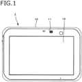
- Figs. 1 and 2 are a front view and a rear view, respectively, of a portable terminal 1 according to the embodiment of the disclosure.
- the portable terminal 1 is a smartphone or an electronic device such as a tablet terminal, a digital camera, a portable personal computer, or a radio device, for uses including personal and business uses.
- a typical example of the portable terminal 1 is a tablet portable terminal that is shock-resistant, vibration-resistant, splash-proof, dust-proof, and of like features, is to be used in business sites of a construction, public safety, transportation, or like compony, and is heavier than common portable terminals.
- the portable terminal 1 has a main body 10 which is mainly made of a resin or a metal and rectangular in a plan view, a display 12 such as a liquid crystal panel or an organic EL panel which is provided in a front surface 11 of the main body 10, and a back surface 13 opposite to the front surface 11.
- the back surface 13 has a terminal 14, a terminal cover 15 which covers the terminal 14, a camera 16, and a battery pack housing region 17.
- the display 12 is equipped with a touch panel that is approximately rectangular in a plan view.
- the display 12 has a UI (user interface) type display function capable of displaying icons, images, information/data, etc. and receiving manipulations.
- the terminal 14 enables electric connection to a barcode reader module 20 (described later).
- the camera 16 enables shooting in a state that the back surface 13 is directed to a target.
- the battery pack housing region 17 is a region for housing a battery pack.
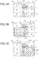
- Regions of the main body 10 will be described with reference to Figs. 3A to 3C .
- the main body 10 is divided into regions S1-S9 (nine divisional matrix regions) in a plan view by imaginary lines L (indicated by broken lines in Figs. 3A-3C ) that divide each of two orthogonal sides 10a and 10b of the main body 10 into three equal parts.
- the term "top side" is defined as one of the two sides 10a and 10b that is located at the top.
- the top side and the lateral side are defined as the longer side 10a and the shorter side 10b, respectively.
- the top side and the lateral side may be defined as the shorter side 10b and the longer side 10a, respectively. That is, the main body 10 may be divided into nine divisional matrix regions S1-S9 with the shorter side 10b as the top side.
- a first region S1, a second region S2, and a third region S3 are defined as the three regions that include the top side 10a and are arranged in this order from the left.
- a fourth region S4, a fifth region S5, and a sixth region S6 are defined as the three regions that are located under the first region S1, the second region S2, and the third region S3, respectively, and are arranged in this order from the left.
- a seventh region S7, an eighth region S8, and a ninth region S9 are defined as the three regions that are located under the fourth region S4, the fifth region S5, and the sixth region S6, respectively, and are arranged in this order from the left.
- a first combined region S10 (hatched in Fig. 3B ) is defined as a combined region of the fourth region S4, the fifth region S5, the seventh region S7, and the eighth region S8.
- a second combined region S20 (hatched in Fig. 3C ) is defined as a combined region of the fifth region S5, the sixth region S6, the eighth region S8, and the ninth region S9.
- the battery pack housing region 17 is provided in the second combined region S20 and the camera 16 is provided in the first region S1 (see Fig. 3C ), this arrangement can be changed.
- the camera 16 may be provided in the third region S3.
- Fig. 4 is an exploded perspective view including a first embodiment bar code reader module 20.
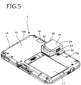
- Fig. 5 is a perspective view, as viewed from the back side, showing a state that the bar code reader module 20 shown in Fig. 4 is attached to the main body 10.
- the first embodiment bar code reader module 20 will be described below with reference to Figs. 4 and 5 .
- the first embodiment bar code reader module 20 is disposed in the second region and assumes a rectangular shape in a plan view.
- the bar code reader module 20 is equipped with a main body 21 and an attachment portion 22 which projects sideways from the main body 21.
- the main body 21 is equipped with a reader camera 23 for reading a barcode, a switch 24 for manipulation for reading by the reader camera 23, a module-side terminal 25 for electric connection to the terminal 14, and a support portion 26 for supporting one end portion of a strap 30 (described later).
- the attachment portion 22 is formed with an insertion hole 28 into which a screw 27 is to be inserted.
- the switch 24 is provided on one side surface of the main body 21, two switches may be provided on two respective side surfaces of the main body 21.
- the barcode reader module 20 is attached to the main body 10 according to the following procedure. First, the terminal cover 15 is removed from the back surface 13 by disengaging the screws that have fixed the terminal cover 15 to the main body 10 and the module-side terminal 25 of the bar code reader module 20 is electrically connected to the terminal 14. Then the barcode reader module 20 is fixed to the back surface 13 by inserting the screw 27 into the insertion hole 28 of the attachment portion 22 and engaging the screw 27 with a screw hole 13a of the main body 10.
- Fig. 6 is an exploded perspective view including a second embodiment bar code reader module 20.
- Fig. 7 is a perspective view, as viewed from the back side, showing a state that the bar code reader module 20 shown in Fig. 6 is attached to the main body 10.
- the second embodiment bar code reader module 20 will be described below with reference to Figs. 6 and 7 .
- the second embodiment bar code reader module 20 is L-shaped in a plan view because the attachment portion 22 extends sideways long from the main body 21.
- the module terminal 25 is provided in the attachment portion 22.
- the reader camera 23 is directed to the outside of the top side 10a because the portable terminal 1 is to be used being oriented horizontally
- the reader camera 23 is directed to the outside of the lateral side 10a because the portable terminal 1 is to be used being oriented vertically.
- the main body 21 of the bar code reader module 20 is disposed in the fourth region S4.
- the second embodiment bar code reader module 20 can be attached to the back surface 13 by removing the terminal cover 15 and then fixing the attachment portion 22 to the back surface 13.
- the user can grip the main body 10 of the portable terminal 1 stably because the heavy battery pack housing region 17 is always located at a low position in the main body 10. Furthermore, whether the main body 10 is used being oriented vertically or horizontally, since the camera 16 is always located at a high position in the back surface 13 of the main body 10, an event that the camera 16 is obstructed by a hand of the user can be avoided. Still further, since a region where to dispose the barcode reader module 20 can always be secured at a high position in the back surface 13 of the main body 10, the user can use the barcode reader module 20 conveniently.
- Fig. 8B shows a first example strap 30 attached to the main body 10 of the portable terminal 1 according to the embodiment
- Fig. 8A is a front view of the first example strap 30
- Fig. 8B is a conceptual diagram showing a state that the first example strap 30 is attached to the main body 10.
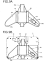
- Fig. 9B shows a second example strap 30 attached to the main body 10 of the portable terminal 1 according to the embodiment;
- Fig. 9A is a front view of the second example strap 30 and
- Fig. 9B is a conceptual diagram showing a state that the second example strap 30 is attached to the main body 10.
- the two kinds of straps 30 will be described below with reference to Figs. 8A and 8B and Figs. 9A and 9B .
- Each of the two kinds of straps 30 for gripping which are made of leather or cloth, are belt-shaped, and are deformable can be attached to the back surface 13 of the main body 10.
- Each kind of straps 30 is equipped with a first member 31 and a second member 32 which is disposed over and connected to the first member 31. A space into which a finger(s) can be inserted to grip the strap 30 is formed between the first member 31 and the second member 32.
- Each kind of straps 30 has three end portions 33 so as to be attached to the back surface 13 of the main body 10 at three positions.
- a first end portion 33a is attached to the main body 21 of the bar code reader module 20, and a second end portion 33b and a third end portion 33c are attached to respective corners of the main body 10 of the portable terminal 1.
- the second end portion 33b and the third end portion 33c are attached to the ninth region S9 and the third region S3 of the main body 10, respectively.
- the second end portion 33b and the third end portion 33c are attached to the seventh region S7 and the ninth region S9 of the main body 10, respectively.
- the first end portion 33a is attached to the support portion 26 of the main body 21 of the bar code reader module 20 by a metal fitting, a thin cord, or the like.
- each of the second end portion 33b and the third end portion 33c is provided with an engagement piece 34 and is attached to the main body 10 by engaging the engagement piece 34 with a lock portion 35 which is attached to the corner of the main body 10 by a known thin cord or the like.
- the second end portion 33b is attached to the main body 10 by hooking, on a metal fitting or the like, a thin cord that is provided on the back side of the second end portion 33b.
- the third end portion 33c is attached to the main body 10 by engaging an engagement piece 34 provided on the third end portion 33c with a lock portion 35 which is attached to the corner of the main body 10.
- the first example strap 3 is attached to the portable terminal 1 with the second embodiment barcode reader module 20 and the second example strap 3 is attached to the portable terminal 1 with the first embodiment barcode reader module 20.
- the example straps 30 that are Y-shaped in a plan view have been described above, I-shaped or X-shaped straps may also be employed. In the case of an I-shaped strap, one end portion 33 is attached to the eighth region S8.
- the second member 32 may be attached to the first member 31 rotatably.
- each of the example straps 30 can protect the main body 10 and is suitable for heavy portable terminals 1 for, for example, business use.
- the bar code reader module 20 can be used stably and the camera 16 that is disposed in the first region S1 or the third region S3 is not obstructed.
- the portable terminal according to the disclosure is useful when applied to fields in which it is equipped with a barcode reader module capable of being used irrespective of whether it is oriented vertically or horizontally.
Landscapes
- Engineering & Computer Science (AREA)
- Physics & Mathematics (AREA)
- Theoretical Computer Science (AREA)
- Electromagnetism (AREA)
- General Physics & Mathematics (AREA)
- Computer Hardware Design (AREA)
- Toxicology (AREA)
- Computer Vision & Pattern Recognition (AREA)
- Artificial Intelligence (AREA)
- General Health & Medical Sciences (AREA)
- Health & Medical Sciences (AREA)
- General Engineering & Computer Science (AREA)
- Human Computer Interaction (AREA)
- Multimedia (AREA)
- Signal Processing (AREA)
- Power Engineering (AREA)
- Telephone Set Structure (AREA)
- Casings For Electric Apparatus (AREA)
Description
- The present invention relates to a portable terminal such as a tablet terminal.
- Electronic devices are known that are equipped with a barcode reader and can accommodate different directions (refer to
JP-UM-A-3-100960 JP-A-2002-109464 -
JP-UM-A-3-100960 -
JP-A-2002-109464 - However, a problem remains that although it is desired to enable manipulations irrespective of whether a device is oriented in any direction when a barcode reader is used, at present there exists no portable terminal that satisfies this desire.
-
EP 3 104 250 A1 provides a modular electronic device, in particular a handheld device comprising a chassis comprising a frame holding a computational module comprising a circuit board holding a data processor, and a display module comprising a planar display device having a viewing side and a rear side, further comprising an expansion port coupled to said circuit board and extending to said rear side for providing coupling at said rear side of said modular device. -
US 2015/0277503 A1 discloses modules and connections for modules to couple to a computing device. An example module includes a housing comprising an end to couple to a computing device, multiple capacitive pads that each include data contacts to enable data transfer, a power contact pad to provide or receive power, and a ground contact pad to couple to ground. The ground contact pad is larger in size than the power contact pad, and the ground contact pad is positioned closer than the power contact pad to the end of the housing configured to couple to the computing device. -
US 5,579,487 discloses a configurable electronic slate unit including a customizable array of data devices and input/output devices which are selectively integrated in a compact and highly ergonomic structure. Selectively integratable user interface components include a bar code scanner, RF modulator for radio frequency communication, modem, audio input/output, as well as the multi-purpose display. - The present disclosure has been made in view of the above circumstances, and an object of this disclosure is therefore to provide a portable terminal that can be manipulated irrespective of whether the portable terminal is oriented vertically or horizontally.
- The invention is defined in the appended claims.
-
-
Fig. 1 is a front view of a portable terminal according to an embodiment of the present invention. -
Fig. 2 is a rear view of the portable terminal shown inFig. 1 . -
Figs. 3A to 3C show regions of the portable terminal according to the embodiment;Fig. 3A shows first to ninth regions,Fig. 3B shows a first combined region, andFig. 3C shows a second combined region. -
Fig. 4 is an exploded perspective view including a first embodiment bar code reader module. -
Fig. 5 is a perspective view showing a state that the bar code reader module shown inFig. 4 is attached to a main body of the portable terminal according to the embodiment. -
Fig. 6 is an exploded perspective view of a second embodiment bar code reader module. -
Fig. 7 is a perspective view showing a state that the bar code reader module shown inFig. 6 is attached to the main body of the portable terminal according to the embodiment. -
Figs. 8A and 8B show a first example strap;Fig. 8A is a front view of the first example strap andFig. 8B is a conceptual diagram showing a state that the first example strap is attached to the portable terminal according to the embodiment. -
Figs. 9A and 9B show a second example strap;Fig. 9A is a front view of the second example strap andFig. 9B is a conceptual diagram showing a state that the second example strap is attached to the portable terminal according to the embodiment. - A portable terminal according to a specific embodiment of the present disclosure will be hereinafter described in detail with reference to the drawings when necessary. However, unnecessarily detailed descriptions will be avoided. For example, a detailed description of a well-known item or a redundant description of substantially the same constituent element as an already described one may be made. This is to prevent the following description from becoming unnecessarily redundant and facilitate understanding of those skilled in the art. The accompanying drawings and the following description are provided to allow those skilled in the art to understand the disclosure thoroughly and are not intended to restrict the subject matter disclosed in the claims.
- The embodiment that is suitable for practice of the disclosure will be hereinafter described in detail with reference to the drawings.
-
Figs. 1 and2 are a front view and a rear view, respectively, of aportable terminal 1 according to the embodiment of the disclosure. - The
portable terminal 1 is a smartphone or an electronic device such as a tablet terminal, a digital camera, a portable personal computer, or a radio device, for uses including personal and business uses. A typical example of theportable terminal 1 is a tablet portable terminal that is shock-resistant, vibration-resistant, splash-proof, dust-proof, and of like features, is to be used in business sites of a construction, public safety, transportation, or like compony, and is heavier than common portable terminals. - The
portable terminal 1 has amain body 10 which is mainly made of a resin or a metal and rectangular in a plan view, adisplay 12 such as a liquid crystal panel or an organic EL panel which is provided in afront surface 11 of themain body 10, and aback surface 13 opposite to thefront surface 11. Theback surface 13 has aterminal 14, aterminal cover 15 which covers theterminal 14, acamera 16, and a batterypack housing region 17. - The
display 12 is equipped with a touch panel that is approximately rectangular in a plan view. Thedisplay 12 has a UI (user interface) type display function capable of displaying icons, images, information/data, etc. and receiving manipulations. Theterminal 14 enables electric connection to a barcode reader module 20 (described later). Thecamera 16 enables shooting in a state that theback surface 13 is directed to a target. The batterypack housing region 17 is a region for housing a battery pack. - Regions of the
main body 10 will be described with reference toFigs. 3A to 3C . - The
main body 10 is divided into regions S1-S9 (nine divisional matrix regions) in a plan view by imaginary lines L (indicated by broken lines inFigs. 3A-3C ) that divide each of twoorthogonal sides main body 10 into three equal parts. The term "top side" is defined as one of the twosides longer side 10a and theshorter side 10b, respectively. (Alternatively, the top side and the lateral side may be defined as theshorter side 10b and thelonger side 10a, respectively. That is, themain body 10 may be divided into nine divisional matrix regions S1-S9 with theshorter side 10b as the top side.) - As shown in
Fig. 3A , a first region S1, a second region S2, and a third region S3 are defined as the three regions that include thetop side 10a and are arranged in this order from the left. A fourth region S4, a fifth region S5, and a sixth region S6 are defined as the three regions that are located under the first region S1, the second region S2, and the third region S3, respectively, and are arranged in this order from the left. A seventh region S7, an eighth region S8, and a ninth region S9 are defined as the three regions that are located under the fourth region S4, the fifth region S5, and the sixth region S6, respectively, and are arranged in this order from the left. - A first combined region S10 (hatched in
Fig. 3B ) is defined as a combined region of the fourth region S4, the fifth region S5, the seventh region S7, and the eighth region S8. A second combined region S20 (hatched inFig. 3C ) is defined as a combined region of the fifth region S5, the sixth region S6, the eighth region S8, and the ninth region S9. - Although in the embodiment the battery
pack housing region 17 is provided in the second combined region S20 and thecamera 16 is provided in the first region S1 (seeFig. 3C ), this arrangement can be changed. For example, as shown inFig. 3B , where the batterypack housing region 17 is located in the first combined region S10, thecamera 16 may be provided in the third region S3. These arrangements can prevent an event that thecamera 16 is obstructed by a hand of the user irrespective of whether themain body 10 is oriented vertically or horizontally. -
Fig. 4 is an exploded perspective view including a first embodiment barcode reader module 20.Fig. 5 is a perspective view, as viewed from the back side, showing a state that the barcode reader module 20 shown inFig. 4 is attached to themain body 10. The first embodiment barcode reader module 20 will be described below with reference toFigs. 4 and5 . - The first embodiment bar
code reader module 20 is disposed in the second region and assumes a rectangular shape in a plan view. The barcode reader module 20 is equipped with amain body 21 and anattachment portion 22 which projects sideways from themain body 21. Themain body 21 is equipped with areader camera 23 for reading a barcode, aswitch 24 for manipulation for reading by thereader camera 23, a module-side terminal 25 for electric connection to the terminal 14, and asupport portion 26 for supporting one end portion of a strap 30 (described later). Theattachment portion 22 is formed with aninsertion hole 28 into which ascrew 27 is to be inserted. Although theswitch 24 is provided on one side surface of themain body 21, two switches may be provided on two respective side surfaces of themain body 21. - The
barcode reader module 20 is attached to themain body 10 according to the following procedure. First, theterminal cover 15 is removed from theback surface 13 by disengaging the screws that have fixed theterminal cover 15 to themain body 10 and the module-side terminal 25 of the barcode reader module 20 is electrically connected to the terminal 14. Then thebarcode reader module 20 is fixed to theback surface 13 by inserting thescrew 27 into theinsertion hole 28 of theattachment portion 22 and engaging thescrew 27 with ascrew hole 13a of themain body 10. -
Fig. 6 is an exploded perspective view including a second embodiment barcode reader module 20.Fig. 7 is a perspective view, as viewed from the back side, showing a state that the barcode reader module 20 shown inFig. 6 is attached to themain body 10. The second embodiment barcode reader module 20 will be described below with reference toFigs. 6 and7 . - The second embodiment bar
code reader module 20 is L-shaped in a plan view because theattachment portion 22 extends sideways long from themain body 21. Themodule terminal 25 is provided in theattachment portion 22. Whereas in the first embodiment thereader camera 23 is directed to the outside of thetop side 10a because theportable terminal 1 is to be used being oriented horizontally, in the second embodiment thereader camera 23 is directed to the outside of thelateral side 10a because theportable terminal 1 is to be used being oriented vertically. Themain body 21 of the barcode reader module 20 is disposed in the fourth region S4. - Like the first embodiment the
reader camera 23, the second embodiment barcode reader module 20 can be attached to theback surface 13 by removing theterminal cover 15 and then fixing theattachment portion 22 to theback surface 13. - Whether the
main body 10 is used being oriented vertically or horizontally, the user can grip themain body 10 of theportable terminal 1 stably because the heavy batterypack housing region 17 is always located at a low position in themain body 10. Furthermore, whether themain body 10 is used being oriented vertically or horizontally, since thecamera 16 is always located at a high position in theback surface 13 of themain body 10, an event that thecamera 16 is obstructed by a hand of the user can be avoided. Still further, since a region where to dispose thebarcode reader module 20 can always be secured at a high position in theback surface 13 of themain body 10, the user can use thebarcode reader module 20 conveniently. -
Fig. 8B shows afirst example strap 30 attached to themain body 10 of theportable terminal 1 according to the embodiment;Fig. 8A is a front view of thefirst example strap 30 andFig. 8B is a conceptual diagram showing a state that thefirst example strap 30 is attached to themain body 10.Fig. 9B shows asecond example strap 30 attached to themain body 10 of theportable terminal 1 according to the embodiment;Fig. 9A is a front view of thesecond example strap 30 andFig. 9B is a conceptual diagram showing a state that thesecond example strap 30 is attached to themain body 10. The two kinds ofstraps 30 will be described below with reference toFigs. 8A and 8B andFigs. 9A and 9B . - Each of the two kinds of
straps 30 for gripping which are made of leather or cloth, are belt-shaped, and are deformable can be attached to theback surface 13 of themain body 10. - Each kind of
straps 30 is equipped with afirst member 31 and asecond member 32 which is disposed over and connected to thefirst member 31. A space into which a finger(s) can be inserted to grip thestrap 30 is formed between thefirst member 31 and thesecond member 32. - Each kind of
straps 30 has three end portions 33 so as to be attached to theback surface 13 of themain body 10 at three positions. Afirst end portion 33a is attached to themain body 21 of the barcode reader module 20, and asecond end portion 33b and athird end portion 33c are attached to respective corners of themain body 10 of theportable terminal 1. - In the
first example strap 30, thesecond end portion 33b and thethird end portion 33c are attached to the ninth region S9 and the third region S3 of themain body 10, respectively. In thesecond example strap 30, thesecond end portion 33b and thethird end portion 33c are attached to the seventh region S7 and the ninth region S9 of themain body 10, respectively. - Examples of various attachment structures will be described below with reference to
Figs. 8 and9 . Thefirst end portion 33a is attached to thesupport portion 26 of themain body 21 of the barcode reader module 20 by a metal fitting, a thin cord, or the like. - In the
first example strap 30, each of thesecond end portion 33b and thethird end portion 33c is provided with anengagement piece 34 and is attached to themain body 10 by engaging theengagement piece 34 with alock portion 35 which is attached to the corner of themain body 10 by a known thin cord or the like. - In the
second example strap 30, thesecond end portion 33b is attached to themain body 10 by hooking, on a metal fitting or the like, a thin cord that is provided on the back side of thesecond end portion 33b. Thethird end portion 33c is attached to themain body 10 by engaging anengagement piece 34 provided on thethird end portion 33c with alock portion 35 which is attached to the corner of themain body 10. - There are no limitations on the structures for attaching the end portions 33 to the
main bodies - As described above, the first example strap 3 is attached to the
portable terminal 1 with the second embodimentbarcode reader module 20 and the second example strap 3 is attached to theportable terminal 1 with the first embodimentbarcode reader module 20. Although the example straps 30 that are Y-shaped in a plan view have been described above, I-shaped or X-shaped straps may also be employed. In the case of an I-shaped strap, one end portion 33 is attached to the eighth region S8. - There are no particular limitations on the plan-view shape of the
strap 30. Thesecond member 32 may be attached to thefirst member 31 rotatably. - Covering the
back surface 13 of themain body 10 over a wide area, each of the example straps 30 can protect themain body 10 and is suitable for heavyportable terminals 1 for, for example, business use. When either of the example straps 30 is used, the barcode reader module 20 can be used stably and thecamera 16 that is disposed in the first region S1 or the third region S3 is not obstructed. - Although the portable terminal according to the embodiment of the disclosure has been described above with reference to the drawings, it goes without saying that the disclosure is not limited to the embodiment. It is apparent that those skilled in the art would conceive various changes, modifications, replacements, additions, deletions, or equivalents within the confines of the claims. And such changes etc. should naturally be construed as being included in the technical scope of the disclosure.
- The portable terminal according to the disclosure is useful when applied to fields in which it is equipped with a barcode reader module capable of being used irrespective of whether it is oriented vertically or horizontally.
Claims (11)
- A portable terminal (1) for use in a vertical and a horizontal orientation comprising:a main body (10) that has a first surface (11) provided with a display (12) and a second surface (13) opposite to the first surface (11) being a back surface (13) of the main body (10), and has a rectangular shape in a plan view;a battery pack housing region (17) configured to house a battery pack;a first camera (16) configured to shoot a target in a state that the second surface (13) is directed to the target, wherein:the first camera (16) is always located at a high position in the second surface (13) of the main body (10) and the battery pack housing region (17) is always located at a low position in the main body (10) irrespective of whether the main body (10) is used in the vertical orientation or the horizontal orientation;the main body (10) is divided into nine divisional matrix regions by drawing imaginary lines (L) that divide each of two sides (10a, 10b) being orthogonal to each other among four sides of the second surface (13) into three equal parts;a top side (10a) is defined as either the longer side (10a) or the shorter side (10b) of the main body (10) that is located at the top of the main body (10) when the main body (10) is used in the vertical orientation and the horizontal orientation, respectively, and a first region (S1), a second region (S2), and a third region (S3) of the main body (10) are defined as three regions including the top side (10a) arranged in this order from the left of the main body (10);a fourth region (S4), a fifth region (S5), and a sixth region (S6) of the main body (10) are defined as three regions that are located under the first region (S1), the second region (S2), and the third region (S3), respectively, and arranged in this order from the left;a seventh region (S7), an eighth region (S8), and a ninth region (S9) of the main body (10) are defined as three regions that are located under the fourth region (S4), the fifth region (S5), and the sixth region (S6), respectively, and are arranged in this order from the left;a first combined region (S10) is defined as a region in which the fourth region (S4), the fifth region (S5), the seventh region (S7), and the eighth region (S8) are combined;a second combined region (S20) is defined as a region in which the fifth region (S5), the sixth region (S6), the eighth region (S8), and the ninth region (S9) are combined;the battery pack housing region (17) is provided in the first combined region (S10) or the second combined region (S20);the first camera (16) is provided in the third region (S3) in a case where the battery pack housing region (17) is located in the first combined region (S10), and the first camera (16) is provided in the first region (S1) in a case where the battery pack housing region (17) is located in the second combined region (S20);characterized in thatthe portable terminal further comprises a barcode reader module (20) being attachable to the second surface (13); whereinthe barcode reader module (20) has a second camera (23) for reading a barcode; whereina switch (24) for manipulation for reading by the second camera (23), is provided on a side surface of the bar code reader module (20);when the barcode reader module (20) is attached to the second surface (13), the second camera (23) is configured to read the barcode in a state that the second surface is directed to the barcode and the second camera is located in the second region of the second surface; andthe barcode reader module (20) having a support portion to which a first end portion (33a) of a strap (30) is attached, wherein the strap (30) is Y-shaped in a plan view having the first end portion (33a), a second end portion (33b) and a third end portion (33c), wherein the second end portion (33b) and the third end portion (33c) are attached to respective corners of the second surface (13) of the main body (10) of the portable terminal (1);and, when the barcode reader module is attached to the second surface, the second camera and the support portion are located in the second region of the second surface.
- The portable terminal (1) according to claim 1, wherein:
the support portion (26) of the barcode reader module (20) is a strap hole and the one end portion (33a) of the strap (30) is bounded to the strap hole. - The portable terminal (1) according to claim 1, wherein:
the one end portion (33a) of the strap (30) is attached to the support portion (26) of the barcode reader module (20) and other end portion (33b) of the strap (30) is attached to the main body (10) so that the strap (30) straddles over the battery pack housing region (17). - The portable terminal (1) according to claim 1, further comprising:
an electric connection terminal (14), configured to conduct electric connection to the barcode reader module (20), which is provided in the second region (S2) of the second surface (13). - The portable terminal (1) according to claim 4, wherein:the barcode reader module (20) has a support portion (26) to which one end portion (33) of a strap (30) is attached; andthe one end portion (33) of the strap (30) is attached to the support portion (26) of the barcode reader module (20) which is attached to the electric connection terminal (14).
- The portable terminal (1) according to claim 5, wherein:
the support portion (26) is a strap hole and the one end portion (33a) of the strap (30) is bounded to the strap hole. - The portable terminal (1) according to claim 5, wherein:
the one end portion (33a) of the strap (30) is attached to the support portion (26) of the barcode reader module (20) and other end portion (33b) of the strap (30) is attached to the main body (10) so that the strap (30) straddles over the battery pack housing region (17). - The portable terminal (1) according to claim 4, wherein:
the barcode reader module (20) is attached to the electric connection terminal (14). - The portable terminal (1) according to claim 8, wherein:the barcode reader module (20) has a support portion (26) to which one end portion (33) of a strap (30) is attached; andthe one end portion (33) of the strap (30) is attached to the support portion (26) of the barcode reader module (20) which is attached to the electric connection terminal (14).
- The portable terminal (1) according to claim 9, wherein:
the support portion (26) is a strap hole and the one end portion (33a) of the strap (30) is bounded to the strap hole. - The portable terminal (1) according to claim 9, wherein:
the one end portion (33a) of the strap (30) is attached to the support portion (26) of the barcode reader module (20) and other end portion (33b) of the strap (30) is attached to the main body (10) so that the strap (30) straddles over the battery pack housing region (17).
Applications Claiming Priority (1)
| Application Number | Priority Date | Filing Date | Title |
|---|---|---|---|
| JP2018085073A JP6365962B1 (en) | 2018-04-26 | 2018-04-26 | Mobile device |
Publications (3)
| Publication Number | Publication Date |
|---|---|
| EP3561637A2 EP3561637A2 (en) | 2019-10-30 |
| EP3561637A3 EP3561637A3 (en) | 2019-11-27 |
| EP3561637B1 true EP3561637B1 (en) | 2025-04-23 |
Family
ID=63036654
Family Applications (1)
| Application Number | Title | Priority Date | Filing Date |
|---|---|---|---|
| EP18215093.8A Active EP3561637B1 (en) | 2018-04-26 | 2018-12-21 | Portable terminal |
Country Status (4)
| Country | Link |
|---|---|
| US (1) | US10528779B2 (en) |
| EP (1) | EP3561637B1 (en) |
| JP (1) | JP6365962B1 (en) |
| CN (1) | CN110414285B (en) |
Families Citing this family (5)
| Publication number | Priority date | Publication date | Assignee | Title |
|---|---|---|---|---|
| JP6844594B2 (en) * | 2018-08-27 | 2021-03-17 | カシオ計算機株式会社 | Hand belt and mobile terminal with hand belt |
| JP6534109B1 (en) | 2018-12-25 | 2019-06-26 | パナソニックIpマネジメント株式会社 | strap |
| JP6748881B1 (en) * | 2019-11-20 | 2020-09-02 | パナソニックIpマネジメント株式会社 | Wireless communication terminal |
| JP6709975B1 (en) * | 2019-11-26 | 2020-06-17 | パナソニックIpマネジメント株式会社 | Wireless communication terminal |
| WO2021215102A1 (en) * | 2020-04-24 | 2021-10-28 | パナソニックIpマネジメント株式会社 | Mobile terminal |
Family Cites Families (30)
| Publication number | Priority date | Publication date | Assignee | Title |
|---|---|---|---|---|
| JP2965584B2 (en) | 1989-09-12 | 1999-10-18 | 富士通株式会社 | Library device |
| US5579487A (en) * | 1992-10-02 | 1996-11-26 | Teletransaction, Inc. | Portable work slate computer with multiple docking positions for interchangeably receiving removable modules |
| JP3183056B2 (en) * | 1994-08-26 | 2001-07-03 | 株式会社日立製作所 | Imaging device |
| JPH10155165A (en) * | 1996-11-20 | 1998-06-09 | Hideo Tamura | Stereoscopic video camera recorder |
| JP2002353715A (en) * | 1998-02-02 | 2002-12-06 | Seiko Epson Corp | Portable information processing device |
| US20020040934A1 (en) | 2000-09-27 | 2002-04-11 | Kunihiko Itou | Compact and low cost manufactured structure of information code reader |
| JP4273649B2 (en) | 2000-09-27 | 2009-06-03 | 株式会社デンソー | Information code reader |
| JP2002164989A (en) * | 2000-11-24 | 2002-06-07 | Olympus Optical Co Ltd | Mobile phone system |
| JP2007158799A (en) * | 2005-12-06 | 2007-06-21 | Sony Corp | Imaging device |
| JP2010081409A (en) * | 2008-09-26 | 2010-04-08 | Toshiba Corp | Mobile terminal |
| JP2010109943A (en) * | 2008-10-31 | 2010-05-13 | Sony Corp | Digital camera |
| JP2010171731A (en) * | 2009-01-22 | 2010-08-05 | Kyocera Corp | Mobile electronic equipment |
| IT1397388B1 (en) * | 2009-12-29 | 2013-01-10 | Datalogic Mobile S R L | PORTABLE DEVICE AND METHOD FOR READING CODIFIED INFORMATION |
| US20120113572A1 (en) * | 2010-06-07 | 2012-05-10 | 360 Mobility Solutions, Llc | Method and system for electronic device cases |
| JP5647819B2 (en) * | 2010-06-11 | 2015-01-07 | 任天堂株式会社 | Portable electronic devices |
| KR101733806B1 (en) * | 2010-08-05 | 2017-05-08 | 삼성전자주식회사 | Portable terminal |
| US8831677B2 (en) * | 2010-11-17 | 2014-09-09 | Antony-Euclid C. Villa-Real | Customer-controlled instant-response anti-fraud/anti-identity theft devices (with true-personal identity verification), method and systems for secured global applications in personal/business e-banking, e-commerce, e-medical/health insurance checker, e-education/research/invention, e-disaster advisor, e-immigration, e-airport/aircraft security, e-military/e-law enforcement, with or without NFC component and system, with cellular/satellite phone/internet/multi-media functions |
| US20160012445A1 (en) * | 2011-11-10 | 2016-01-14 | Antony-Euclid C. Villa-Real | Customer-controlled instant-response anti-fraud/anti-identity theft devices (with true-personal identity verification), methods and systems for secured global applications in personal/business e-banking, e-commerce, e-medical/health insurance checker, e-education/research/invention, e-disaster advisor, e-immigration, e-airport/aircraft security, e-military/e-law enforcement, with or without nfc component and system, with cellular/satellite phone/internet/multi-media functions |
| KR20130098053A (en) * | 2012-02-27 | 2013-09-04 | 엘지전자 주식회사 | Mobile terminal |
| JP2014045251A (en) * | 2012-08-24 | 2014-03-13 | Sanyo Electric Co Ltd | Portable information terminal device |
| US8844817B2 (en) * | 2013-01-05 | 2014-09-30 | Otter Products, Llc | Electronic device case for mobile point of sale |
| JP5541430B1 (en) * | 2013-08-19 | 2014-07-09 | ソニー株式会社 | Imaging unit, mounting device |
| US9823703B2 (en) * | 2014-03-27 | 2017-11-21 | Google Inc. | Modules and connections for modules to couple to a computing device |
| EP3104250A1 (en) * | 2015-06-10 | 2016-12-14 | FairPhone B.V. | Modular electronic device |
| CN106559524A (en) * | 2015-09-28 | 2017-04-05 | 杨挺 | Modularized splice smart mobile phone |
| KR102483377B1 (en) * | 2015-11-30 | 2023-01-02 | 삼성전자주식회사 | Electronic device and method of manufacturing the same |
| KR102419624B1 (en) * | 2016-01-21 | 2022-07-11 | 삼성전자 주식회사 | Arrangement structure of sensor of electronic apparatus |
| WO2017125982A1 (en) * | 2016-01-21 | 2017-07-27 | パナソニックIpマネジメント株式会社 | Electronic apparatus |
| JP6300133B1 (en) * | 2017-08-10 | 2018-03-28 | パナソニックIpマネジメント株式会社 | Electronics |
| CN107908995A (en) * | 2017-12-13 | 2018-04-13 | 成都合能创越软件有限公司 | Multi-functional law enforcement terminal |
-
2018
- 2018-04-26 JP JP2018085073A patent/JP6365962B1/en active Active
- 2018-12-21 EP EP18215093.8A patent/EP3561637B1/en active Active
- 2018-12-27 US US16/234,024 patent/US10528779B2/en active Active
- 2018-12-27 CN CN201811608083.7A patent/CN110414285B/en active Active
Also Published As
| Publication number | Publication date |
|---|---|
| JP2019193136A (en) | 2019-10-31 |
| JP6365962B1 (en) | 2018-08-01 |
| CN110414285B (en) | 2024-07-19 |
| EP3561637A3 (en) | 2019-11-27 |
| US20190332836A1 (en) | 2019-10-31 |
| US10528779B2 (en) | 2020-01-07 |
| EP3561637A2 (en) | 2019-10-30 |
| CN110414285A (en) | 2019-11-05 |
Similar Documents
| Publication | Publication Date | Title |
|---|---|---|
| EP3561637B1 (en) | Portable terminal | |
| US6788529B2 (en) | Portable computer having multiport bay | |
| US9274557B2 (en) | Stand for electronic device and electronic device | |
| US7337257B2 (en) | Adapter unit for a personal digital assistant having automatically configurable application buttons | |
| US6525928B1 (en) | Case with communication module having a latching connector for a handheld computer system | |
| US6820813B2 (en) | Adapter unit having an ergonomic grip for a personal digital assistant | |
| KR100655549B1 (en) | Portable hybrid computer | |
| US8570226B2 (en) | Portable electronic device with near field communication function | |
| US8971049B1 (en) | Portable electronic device having integrated peripheral expansion module | |
| US20160179143A1 (en) | Tablet computer with interface channels | |
| US8199524B2 (en) | Electronic device and metal plate member | |
| KR101164098B1 (en) | Mobile terminal | |
| US20070038517A1 (en) | Point-of-sale terminal | |
| US20140355210A1 (en) | Stand for electronic device and electronic device | |
| JP2008500613A (en) | Peripheral devices suitable for portable host devices of different sizes | |
| US7515425B2 (en) | Electronic device and cooling unit | |
| JP7780748B2 (en) | Mobile devices | |
| US7876568B2 (en) | Electronic device | |
| US20080018552A1 (en) | Electronic apparatus | |
| EP1434410B1 (en) | Telephone set attaching member and portable telephone set | |
| US9107288B2 (en) | Electronic apparatus | |
| KR200471353Y1 (en) | Case for portable electronic device | |
| JP2019192187A (en) | Portable terminal | |
| JP3897166B2 (en) | Portable information terminal | |
| JP2006235844A (en) | Portable electronic devices |
Legal Events
| Date | Code | Title | Description |
|---|---|---|---|
| PUAI | Public reference made under article 153(3) epc to a published international application that has entered the european phase |
Free format text: ORIGINAL CODE: 0009012 |
|
| STAA | Information on the status of an ep patent application or granted ep patent |
Free format text: STATUS: THE APPLICATION HAS BEEN PUBLISHED |
|
| PUAL | Search report despatched |
Free format text: ORIGINAL CODE: 0009013 |
|
| AK | Designated contracting states |
Kind code of ref document: A2 Designated state(s): AL AT BE BG CH CY CZ DE DK EE ES FI FR GB GR HR HU IE IS IT LI LT LU LV MC MK MT NL NO PL PT RO RS SE SI SK SM TR |
|
| AX | Request for extension of the european patent |
Extension state: BA ME |
|
| AK | Designated contracting states |
Kind code of ref document: A3 Designated state(s): AL AT BE BG CH CY CZ DE DK EE ES FI FR GB GR HR HU IE IS IT LI LT LU LV MC MK MT NL NO PL PT RO RS SE SI SK SM TR |
|
| AX | Request for extension of the european patent |
Extension state: BA ME |
|
| RIC1 | Information provided on ipc code assigned before grant |
Ipc: H04M 1/02 20060101ALI20191022BHEP Ipc: G06F 1/16 20060101AFI20191022BHEP |
|
| STAA | Information on the status of an ep patent application or granted ep patent |
Free format text: STATUS: REQUEST FOR EXAMINATION WAS MADE |
|
| 17P | Request for examination filed |
Effective date: 20200527 |
|
| RBV | Designated contracting states (corrected) |
Designated state(s): AL AT BE BG CH CY CZ DE DK EE ES FI FR GB GR HR HU IE IS IT LI LT LU LV MC MK MT NL NO PL PT RO RS SE SI SK SM TR |
|
| STAA | Information on the status of an ep patent application or granted ep patent |
Free format text: STATUS: EXAMINATION IS IN PROGRESS |
|
| 17Q | First examination report despatched |
Effective date: 20201014 |
|
| GRAP | Despatch of communication of intention to grant a patent |
Free format text: ORIGINAL CODE: EPIDOSNIGR1 |
|
| STAA | Information on the status of an ep patent application or granted ep patent |
Free format text: STATUS: GRANT OF PATENT IS INTENDED |
|
| INTG | Intention to grant announced |
Effective date: 20241209 |
|
| RIN1 | Information on inventor provided before grant (corrected) |
Inventor name: TANAKA, YASUYUKI Inventor name: MOCHIZUKI, KENICHI |
|
| GRAS | Grant fee paid |
Free format text: ORIGINAL CODE: EPIDOSNIGR3 |
|
| GRAA | (expected) grant |
Free format text: ORIGINAL CODE: 0009210 |
|
| STAA | Information on the status of an ep patent application or granted ep patent |
Free format text: STATUS: THE PATENT HAS BEEN GRANTED |
|
| AK | Designated contracting states |
Kind code of ref document: B1 Designated state(s): AL AT BE BG CH CY CZ DE DK EE ES FI FR GB GR HR HU IE IS IT LI LT LU LV MC MK MT NL NO PL PT RO RS SE SI SK SM TR |
|
| REG | Reference to a national code |
Ref country code: GB Ref legal event code: FG4D |
|
| REG | Reference to a national code |
Ref country code: CH Ref legal event code: EP |
|
| REG | Reference to a national code |
Ref country code: DE Ref legal event code: R096 Ref document number: 602018081269 Country of ref document: DE |
|
| REG | Reference to a national code |
Ref country code: IE Ref legal event code: FG4D |
|
| REG | Reference to a national code |
Ref country code: NL Ref legal event code: MP Effective date: 20250423 |
|
| PG25 | Lapsed in a contracting state [announced via postgrant information from national office to epo] |
Ref country code: NL Free format text: LAPSE BECAUSE OF FAILURE TO SUBMIT A TRANSLATION OF THE DESCRIPTION OR TO PAY THE FEE WITHIN THE PRESCRIBED TIME-LIMIT Effective date: 20250423 |
|
| REG | Reference to a national code |
Ref country code: AT Ref legal event code: MK05 Ref document number: 1788379 Country of ref document: AT Kind code of ref document: T Effective date: 20250423 |
|
| PG25 | Lapsed in a contracting state [announced via postgrant information from national office to epo] |
Ref country code: FI Free format text: LAPSE BECAUSE OF FAILURE TO SUBMIT A TRANSLATION OF THE DESCRIPTION OR TO PAY THE FEE WITHIN THE PRESCRIBED TIME-LIMIT Effective date: 20250423 Ref country code: ES Free format text: LAPSE BECAUSE OF FAILURE TO SUBMIT A TRANSLATION OF THE DESCRIPTION OR TO PAY THE FEE WITHIN THE PRESCRIBED TIME-LIMIT Effective date: 20250423 Ref country code: PT Free format text: LAPSE BECAUSE OF FAILURE TO SUBMIT A TRANSLATION OF THE DESCRIPTION OR TO PAY THE FEE WITHIN THE PRESCRIBED TIME-LIMIT Effective date: 20250825 |
|
| REG | Reference to a national code |
Ref country code: LT Ref legal event code: MG9D |
|
| PG25 | Lapsed in a contracting state [announced via postgrant information from national office to epo] |
Ref country code: NO Free format text: LAPSE BECAUSE OF FAILURE TO SUBMIT A TRANSLATION OF THE DESCRIPTION OR TO PAY THE FEE WITHIN THE PRESCRIBED TIME-LIMIT Effective date: 20250723 Ref country code: GR Free format text: LAPSE BECAUSE OF FAILURE TO SUBMIT A TRANSLATION OF THE DESCRIPTION OR TO PAY THE FEE WITHIN THE PRESCRIBED TIME-LIMIT Effective date: 20250724 |
|
| PG25 | Lapsed in a contracting state [announced via postgrant information from national office to epo] |
Ref country code: PL Free format text: LAPSE BECAUSE OF FAILURE TO SUBMIT A TRANSLATION OF THE DESCRIPTION OR TO PAY THE FEE WITHIN THE PRESCRIBED TIME-LIMIT Effective date: 20250423 |
|
| PG25 | Lapsed in a contracting state [announced via postgrant information from national office to epo] |
Ref country code: BG Free format text: LAPSE BECAUSE OF FAILURE TO SUBMIT A TRANSLATION OF THE DESCRIPTION OR TO PAY THE FEE WITHIN THE PRESCRIBED TIME-LIMIT Effective date: 20250423 |
|
| PG25 | Lapsed in a contracting state [announced via postgrant information from national office to epo] |
Ref country code: HR Free format text: LAPSE BECAUSE OF FAILURE TO SUBMIT A TRANSLATION OF THE DESCRIPTION OR TO PAY THE FEE WITHIN THE PRESCRIBED TIME-LIMIT Effective date: 20250423 |
|
| PG25 | Lapsed in a contracting state [announced via postgrant information from national office to epo] |
Ref country code: AT Free format text: LAPSE BECAUSE OF FAILURE TO SUBMIT A TRANSLATION OF THE DESCRIPTION OR TO PAY THE FEE WITHIN THE PRESCRIBED TIME-LIMIT Effective date: 20250423 |
|
| PG25 | Lapsed in a contracting state [announced via postgrant information from national office to epo] |
Ref country code: RS Free format text: LAPSE BECAUSE OF FAILURE TO SUBMIT A TRANSLATION OF THE DESCRIPTION OR TO PAY THE FEE WITHIN THE PRESCRIBED TIME-LIMIT Effective date: 20250723 |
|
| PG25 | Lapsed in a contracting state [announced via postgrant information from national office to epo] |
Ref country code: IS Free format text: LAPSE BECAUSE OF FAILURE TO SUBMIT A TRANSLATION OF THE DESCRIPTION OR TO PAY THE FEE WITHIN THE PRESCRIBED TIME-LIMIT Effective date: 20250823 |
|
| PG25 | Lapsed in a contracting state [announced via postgrant information from national office to epo] |
Ref country code: LV Free format text: LAPSE BECAUSE OF FAILURE TO SUBMIT A TRANSLATION OF THE DESCRIPTION OR TO PAY THE FEE WITHIN THE PRESCRIBED TIME-LIMIT Effective date: 20250423 |
|
| PGFP | Annual fee paid to national office [announced via postgrant information from national office to epo] |
Ref country code: GB Payment date: 20251219 Year of fee payment: 8 |
|
| PG25 | Lapsed in a contracting state [announced via postgrant information from national office to epo] |
Ref country code: SM Free format text: LAPSE BECAUSE OF FAILURE TO SUBMIT A TRANSLATION OF THE DESCRIPTION OR TO PAY THE FEE WITHIN THE PRESCRIBED TIME-LIMIT Effective date: 20250423 Ref country code: DK Free format text: LAPSE BECAUSE OF FAILURE TO SUBMIT A TRANSLATION OF THE DESCRIPTION OR TO PAY THE FEE WITHIN THE PRESCRIBED TIME-LIMIT Effective date: 20250423 |
|
| PG25 | Lapsed in a contracting state [announced via postgrant information from national office to epo] |
Ref country code: CZ Free format text: LAPSE BECAUSE OF FAILURE TO SUBMIT A TRANSLATION OF THE DESCRIPTION OR TO PAY THE FEE WITHIN THE PRESCRIBED TIME-LIMIT Effective date: 20250423 |
|
| PG25 | Lapsed in a contracting state [announced via postgrant information from national office to epo] |
Ref country code: EE Free format text: LAPSE BECAUSE OF FAILURE TO SUBMIT A TRANSLATION OF THE DESCRIPTION OR TO PAY THE FEE WITHIN THE PRESCRIBED TIME-LIMIT Effective date: 20250423 |
|
| REG | Reference to a national code |
Ref country code: DE Ref legal event code: R097 Ref document number: 602018081269 Country of ref document: DE |
|
| PG25 | Lapsed in a contracting state [announced via postgrant information from national office to epo] |
Ref country code: SK Free format text: LAPSE BECAUSE OF FAILURE TO SUBMIT A TRANSLATION OF THE DESCRIPTION OR TO PAY THE FEE WITHIN THE PRESCRIBED TIME-LIMIT Effective date: 20250423 Ref country code: RO Free format text: LAPSE BECAUSE OF FAILURE TO SUBMIT A TRANSLATION OF THE DESCRIPTION OR TO PAY THE FEE WITHIN THE PRESCRIBED TIME-LIMIT Effective date: 20250423 |
|
| PG25 | Lapsed in a contracting state [announced via postgrant information from national office to epo] |
Ref country code: IT Free format text: LAPSE BECAUSE OF FAILURE TO SUBMIT A TRANSLATION OF THE DESCRIPTION OR TO PAY THE FEE WITHIN THE PRESCRIBED TIME-LIMIT Effective date: 20250423 |
|
| PLBE | No opposition filed within time limit |
Free format text: ORIGINAL CODE: 0009261 |
|
| STAA | Information on the status of an ep patent application or granted ep patent |
Free format text: STATUS: NO OPPOSITION FILED WITHIN TIME LIMIT |
|
| REG | Reference to a national code |
Ref country code: CH Ref legal event code: L10 Free format text: ST27 STATUS EVENT CODE: U-0-0-L10-L00 (AS PROVIDED BY THE NATIONAL OFFICE) Effective date: 20260304 |
|
| 26N | No opposition filed |
Effective date: 20260126 |