EP3561562A1 - Cleaning device for optical connector - Google Patents
Cleaning device for optical connector Download PDFInfo
- Publication number
- EP3561562A1 EP3561562A1 EP17895789.0A EP17895789A EP3561562A1 EP 3561562 A1 EP3561562 A1 EP 3561562A1 EP 17895789 A EP17895789 A EP 17895789A EP 3561562 A1 EP3561562 A1 EP 3561562A1
- Authority
- EP
- European Patent Office
- Prior art keywords
- reel
- take
- cleaning unit
- cleaning
- head
- Prior art date
- Legal status (The legal status is an assumption and is not a legal conclusion. Google has not performed a legal analysis and makes no representation as to the accuracy of the status listed.)
- Withdrawn
Links
- 238000004140 cleaning Methods 0.000 title claims abstract description 251
- 230000003287 optical effect Effects 0.000 title claims abstract description 24
- 230000033001 locomotion Effects 0.000 claims description 36
- 230000032258 transport Effects 0.000 claims description 23
- 238000006243 chemical reaction Methods 0.000 claims description 14
- 238000011144 upstream manufacturing Methods 0.000 claims description 7
- 238000005549 size reduction Methods 0.000 abstract description 13
- 230000005540 biological transmission Effects 0.000 description 30
- 238000010586 diagram Methods 0.000 description 19
- 230000000052 comparative effect Effects 0.000 description 7
- 210000003813 thumb Anatomy 0.000 description 2
- 238000006073 displacement reaction Methods 0.000 description 1
- 230000000694 effects Effects 0.000 description 1
- 210000003811 finger Anatomy 0.000 description 1
Images


Classifications
-
- G—PHYSICS
- G02—OPTICS
- G02B—OPTICAL ELEMENTS, SYSTEMS OR APPARATUS
- G02B6/00—Light guides; Structural details of arrangements comprising light guides and other optical elements, e.g. couplings
- G02B6/24—Coupling light guides
- G02B6/36—Mechanical coupling means
- G02B6/38—Mechanical coupling means having fibre to fibre mating means
- G02B6/3807—Dismountable connectors, i.e. comprising plugs
- G02B6/3833—Details of mounting fibres in ferrules; Assembly methods; Manufacture
- G02B6/3866—Devices, tools or methods for cleaning connectors
-
- B08B1/10—
-
- B08B1/30—
-
- B08B1/32—
-
- B—PERFORMING OPERATIONS; TRANSPORTING
- B08—CLEANING
- B08B—CLEANING IN GENERAL; PREVENTION OF FOULING IN GENERAL
- B08B2240/00—Type of materials or objects being cleaned
- B08B2240/02—Optical fibers or optical fiber connectors
-
- B—PERFORMING OPERATIONS; TRANSPORTING
- B08—CLEANING
- B08B—CLEANING IN GENERAL; PREVENTION OF FOULING IN GENERAL
- B08B7/00—Cleaning by methods not provided for in a single other subclass or a single group in this subclass
- B08B7/0028—Cleaning by methods not provided for in a single other subclass or a single group in this subclass by adhesive surfaces
Definitions
- the present invention relates to a cleaning tool for an optical connector.
- Patent Literatures 1 and 2 describe a cleaning tool that cleans a bonding endface of an optical connector by pressing a cleaning tape (cleaning unit) wound around a pressing surface of a head against the bonding endface of the optical connector.
- the cleaning tape is taken up to a take-up reel, and the cleaning tape is also supplied from a supply reel.
- Patent Literatures 4 and 5 describe that a board to which the cleaning tool is attached is slid into a guide groove when an optical connector (backplane connector) attached to a backplane board located at the back of a plug-in unit is cleaned (cf. Fig. 5 in Patent Literature 4, for example).
- An objective of the present invention is to achieve size reduction of a cleaning tool.
- a main aspect of the invention to achieve the above objective is a cleaning tool for cleaning an optical connector, the cleaning tool including: a head that presses a cleaning unit against the optical connector; a supply reel that supplies the cleaning unit to the head; and a take-up reel that takes up the cleaning unit collected from the head, wherein the supply reel and the take-up reel are arranged rotatably about a common rotation shaft.
- a cleaning tool for cleaning an optical connector will become clear, the cleaning tool including: a head that presses a cleaning unit against the optical connector; a supply reel that supplies the cleaning unit to the head; and a take-up reel that takes up the cleaning unit collected from the head, wherein the supply reel and the take-up reel are arranged rotatably about a common rotation shaft.
- the cleaning tool preferably, further including: a guiding section that keeps a position of the cleaning unit in a width direction on an upstream side of the head to be aligned with a position of the cleaning unit in the width direction on a downstream side of the head.
- a guiding section that keeps a position of the cleaning unit in a width direction on an upstream side of the head to be aligned with a position of the cleaning unit in the width direction on a downstream side of the head.
- a driven roller that transports the cleaning unit in a transport path from the supply reel to the guiding section and a driven roller that transports the cleaning unit in a transport path from the guiding section to the take-up reel are arranged rotatably about a common rotation shaft. In this way, size reduction of the cleaning tool can be achieved.
- the driven roller includes a shaft section and a pair of flange sections protruding from the shaft section on both ends of the shaft section; and an inner surface of each of the flange sections is a tapered surface having a diameter gradually increased toward the outside in a width direction.
- an inner surface of each of the flange sections is a tapered surface having a diameter gradually increased toward the outside in a width direction.
- the cleaning tool preferably further including: a conversion mechanism for converting a linear motion in a cleaning operation to a rotary motion; and a clutch mechanism for rotating the take-up reel in a take-up direction by the rotary motion generated by conversion with the conversion mechanism by restricting a rotation direction of the take-up reel to one direction.
- a conversion mechanism for converting a linear motion in a cleaning operation to a rotary motion preferably further including: a conversion mechanism for converting a linear motion in a cleaning operation to a rotary motion; and a clutch mechanism for rotating the take-up reel in a take-up direction by the rotary motion generated by conversion with the conversion mechanism by restricting a rotation direction of the take-up reel to one direction.
- the conversion mechanism includes a rack that makes the linear motion, and a pinion that makes the rotary motion by the linear motion of the rack; and the pinion is arranged rotatably about the common rotation shaft shared by the supply reel and the take-up reel. In this way, size reduction of the cleaning tool can be achieved.
- the cleaning tool includes a plurality of the take-up reels; a plurality of the pinions are provided for the rack; and the take-up reels are provided for the respective pinions.
- the cleaning unit can be taken up to the plurality of take-up reels by using the linear motion in the cleaning operation.
- Fig. 1A is a partial cross-sectional view of a cleaning tool 10 according to a first embodiment.
- An upper diagram in Fig. 1A is a partial cross-sectional view when seen from a side surface.
- a lower diagram in Fig. 1A is a partial cross-sectional view when seen from an upper surface.
- a direction in which the cleaning tool 10 is brought close to and away from an optical connector (not illustrated) to be cleaned is a "front-rear direction", an optical connector side when seen from the cleaning tool 10 is "front”, and an opposite side is “rear”.
- the front-rear direction is a direction perpendicular to a width direction of a cleaning unit 1, and is a direction perpendicular to a rotation shaft 15 of a take-up reel 13 and a supply reel 12.
- the cleaning tool 10 is a tool used for cleaning an optical connector.
- the cleaning tool 10 includes a head 11, the supply reel 12, and the take-up reel 13.
- the head 11 is a member for pressing the cleaning unit 1 against a connecting end face of an optical connector (ferrule endface) (not illustrated) to be cleaned.
- An endface of the head 11 is a pressing surface for pressing the cleaning unit 1 against the connecting end face of the optical connector.
- the cleaning unit 1 is put around the pressing surface (endface of the head 11).
- An unused cleaning unit 1 is supplied from an upstream side of the pressing surface, and a used cleaning unit 1 is also fed to a downstream side of the pressing surface.
- the supply reel 12 is a reel (cylindrical spool) for supplying the cleaning unit 1.
- the unused cleaning unit 1 is previously wound around the supply reel 12.
- the supply reel 12 is rotatably supported by the rotation shaft 15 in a housing 21. When the cleaning unit 1 is pulled from a head 11 side, the supply reel 12 is rotated by tension of the cleaning unit 1, and the cleaning unit 1 is supplied from the supply reel 12.
- the take-up reel 13 is a reel for taking up the cleaning unit 1.
- the used cleaning unit 1 is taken up to the take-up reel 13.
- the take-up reel 13 is rotatably supported by the rotation shaft 15 in the housing 21. When the take-up reel 13 is rotated, the cleaning unit 1 is taken up to the take-up reel 13.
- the supply reel 12 and the take-up reel 13 are housed in the housing 21.
- the housing 21 is a member (cover) for housing the supply reel 12 and the take-up reel 13.
- the housing 21 is provided with the rotation shaft 15 that rotatably supports the supply reel 12 and the take-up reel 13.
- the rotation shaft 15 is arranged in parallel with the width direction of the cleaning unit 1, and the supply reel 12 and the take-up reel 13 are aligned in the width direction of the cleaning unit 1 and housed in the housing 21.
- the housing 21 is provided with a guiding section 23.
- the guiding section 23 is a section for guiding the cleaning unit 1 in the front-rear direction while restricting movement of the cleaning unit 1 in the width direction during transportation.
- the guiding section 23 is configured to be narrower in the width direction than a section (housing section) for housing the supply reel 12 and the take-up reel 13. In this way, the guiding section 23 can keep a position of the cleaning unit 1 in the width direction on the upstream side of the head 11 to be aligned with a position of the cleaning unit 1 in the width direction on the downstream side of the head 11.
- a position in which the cleaning unit 1 is supplied from the supply reel 12 and a position in which the cleaning unit 1 is taken up to the take-up reel 13 are different positions in the width direction (because the supply reel 12 and the take-up reel 13 are arranged rotatably about the common rotation shaft 15), but misalignment of the cleaning unit 1 in the width direction put around the pressing surface of the head 11 can be suppressed by providing the cleaning tool 10 with the guiding section 23.
- an operation dial 31 is provided as a mechanism for rotating the take-up reel 13.
- the operation dial 31 is a disk-shaped section rotating integrally with the take-up reel 13. A part of the operation dial 31 is exposed from the housing 21, and operable with a thumb or a finger(s) by an operator.
- the operator When an optical connector is cleaned by using the cleaning tool 10, the operator holds the cleaning tool 10 over the housing 21, presses the cleaning tool 1 of the head 11 against the optical connector, and rotates the operation dial 31 with a thumb in this state.
- the take-up reel 13 When a rotation operation is performed on the operation dial 31, the take-up reel 13 is rotated in a take-up direction, which causes the used cleaning unit 1 to be taken up to the take-up reel 13 and also causes the unused cleaning unit 1 having a length corresponding to a take-up length to be supplied from the supply reel 12.
- Fig. 1B is a partial cross-sectional view of a cleaning tool 10 according to a comparative example.
- a rotation shaft of a take-up reel 13 and a rotation shaft of a supply reel 12 are separately provided.
- an area of the cleaning tool 10 occupied in a plane perpendicular to the rotation shaft is larger.
- the supply reel 12 and the take-up reel 13 are arranged rotatably about the common rotation shaft 15 in this embodiment.
- an area of the cleaning tool 10 occupied in the plane perpendicular to the rotation shaft 15 can be reduced than that in the comparative example (cf. upper diagram of Fig. 1A ), and size reduction of the cleaning tool 10 can be achieved.
- Fig. 2A is a perspective view of a cleaning tool 10 according to a second embodiment.
- Fig. 2B is a perspective view of the cleaning tool 10 according to the second embodiment in a state where a body housing 21A is removed.
- the cleaning tool 10 includes a head 11, a supply reel 12, and a take-up reel 13.
- a cleaning unit 1 is put around a pressing surface of the head 11 (front endface of the head 11).
- An unused cleaning unit 1 is supplied from an upstream side of the pressing surface, and a used cleaning unit 1 is also fed to a downstream side of the pressing surface.
- the unused cleaning unit 1 is wound around the supply reel 12, and the supply reel 12 is rotatably supported by a rotation shaft 15 of the body housing 21A.
- the take-up reel 13 is rotatably supported by the rotation shaft 15 of the body housing 21A.
- the supply reel 12 and the take-up reel 13 are arranged rotatably about the common rotation shaft 15. When the take-up reel 13 is rotated, the cleaning unit 1 is taken up to the take-up reel 13. A mechanism for rotating the take-up reel 13 will be described later.
- the cleaning tool 10 in the second embodiment includes a tool body 41 and an extending section 43.
- the tool body 41 is a member that houses the supply reel 12 and the take-up reel 13.
- the tool body 41 includes the supply reel 12 and the take-up reel 13, and also includes the body housing 21A (reel housing, reel cover).
- the body housing 21A is a member that houses the supply reel 12 and the take-up reel 13.
- the body housing 21A includes the rotation shaft 15 that rotatably supports the supply reel 12 and the take-up reel 13.
- the extending section 43 is a member extending from the tool body 41 toward the front and a member that houses the head 11.
- the extending section 43 is movable (extendable) in the front-rear direction with respect to the tool body 41.
- the extending section 43 includes the head 11 and also includes a head housing 21B.
- the head housing 21B is a member (head cover) that houses the head 11 while exposing the head 11 from the front side.
- the head housing 21B is a tubular member.
- the head 11 (and the cleaning unit 1) is exposed from a front opening of the tubular head housing 21B.
- a rear opening of the tubular head housing 21B is arranged inside the tool body 41. Through the rear opening of the tubular head housing 21B, the unused cleaning unit 1 is supplied from the supply reel 12, and the used cleaning unit 1 is also fed to the take-up reel 13.
- the head housing 21B is provided with a guiding section 23.
- the guiding section 23 is a section for guiding the cleaning unit 1 in the front-rear direction while restricting movement of the cleaning unit 1 in the width direction during transportation.
- a groove part is formed in each of upper and lower surfaces of the guiding section 23 along the front-rear direction (the groove part in the lower surface is not illustrated), and a movement range of the cleaning unit 1 in the width direction is restricted by transporting the cleaning unit 1 in the groove parts.
- the groove parts in the upper and lower surfaces of the guiding section 23 are formed in substantially the same positions in the width direction.
- the guiding section 23 can keep a position of the cleaning unit 1 in the width direction on the upstream side of the head 11 to be aligned with a position of the cleaning unit 1 in the width direction on the downstream side of the head 11.
- the supply reel 12 and the take-up reel 13 are arranged rotatably about the common rotation shaft 15, a position in which the cleaning unit 1 is supplied from the supply reel 12 and a position in which the cleaning unit 1 is taken up to the take-up reel 13 are different positions in the width direction.
- misalignment, in the width direction, of the cleaning unit 1 put around the pressing surface of the head 11 can be suppressed by providing the cleaning tool 10 with the guiding section 23.
- the guiding section 23 is also a member that guides the head 11 in the front-rear direction (a section that guides the head 11 in the front-rear direction is not illustrated).
- Figs. 3A and 3B are explanatory diagrams for illustrating an operation in a cleaning operation in the second embodiment, and are also explanatory diagrams for illustrating a take-up mechanism.
- Fig. 3A is an explanatory diagram for illustrating a situation in a push operation.
- Fig. 3B is an explanatory diagram for illustrating a situation in a pull operation.
- the tool body 41 and the extending section 43 make a relative movement (linear movement) in the front-rear direction by the push operation and the pull operation performed on the cleaning tool 10 by the operator in the cleaning operation.
- the cleaning tool 10 in the second embodiment uses this relative movement to rotate the take-up reel 13 in the take-up direction, which causes the used cleaning unit 1 to be taken up to the take-up reel 13 and also causes the unused cleaning unit 1 having a length corresponding to a take-up length to be supplied from the supply reel 12.
- the cleaning tool 10 includes, as the take-up mechanism for taking up the cleaning unit 1, a conversion mechanism 51 and a clutch mechanism 53.
- the conversion mechanism 51 is a mechanism for converting the relative linear motion of the tool body 41 and the extending section 43 to a rotary motion.
- the conversion mechanism 51 is constituted by a rack-and-pinion mechanism, and includes a rack 51A and a pinion 51B.
- the rack 51A is a linear gear provided on an extending section 43 side, and makes a reciprocating motion linearly along the front-rear direction with respect to the tool body 41 (cf. Figs. 3A and 3B ).
- the pinion 51B is a circular gear provided on a tool body 41 side.
- the pinion 51B is provided on a transmission wheel 17, and the transmission wheel 17 is arranged rotatably about the rotation shaft 15 shared by the supply reel 12 and the take-up reel 13.
- the pinion 51B (transmission wheel 17) makes a reciprocating motion (swing motion) along the rotation direction with the rotation shaft 15 as the center ( Figs. 3A and 3B ) .
- the clutch mechanism 53 is a mechanism for restricting the rotation direction of the take-up reel 13 to one direction (take-up direction of the cleaning unit 1).
- the clutch mechanism 53 is constituted by a friction transmission mechanism 531 and a reverse rotation preventing mechanism 532.
- the friction transmission mechanism 531 is a mechanism for transmitting force by frictional force.
- the friction transmission mechanism 531 includes a friction plate 531A provided on the transmission wheel 17 and a friction surface 531B provided on the take-up reel 13.
- the reverse rotation preventing mechanism 532 is a mechanism for preventing the take-up reel 13 from rotating in a reverse direction to the take-up direction in which the cleaning unit 1 is taken up.
- the reverse rotation preventing mechanism 532 is constituted by a ratchet mechanism, and includes a non-return pawl 532B attached to the body housing 21A of the tool body 41 and a ratchet wheel 532A (ratchet) provided on the take-up reel 13.
- the reverse rotation preventing mechanism 532 in this embodiment is constituted by an internal gear ratchet mechanism, but the reverse rotation preventing mechanism 532 may be an external gear ratchet mechanism or a mechanism other than the ratchet mechanism as long as the reverse rotation preventing mechanism 532 is a mechanism capable of preventing a reverse rotation of the take-up reel 13.
- the cleaning tool 10 in this embodiment includes, as a take-up mechanism for taking up the cleaning unit 1 to the take-up reel 13, the rack 51A, the transmission wheel 17 including the pinion 51B and the friction plate 531A, and the take-up reel 13 including the friction surface 531B and the ratchet wheel 532A (ratchet) .
- the transmission wheel 17 (pinion 51B) is arranged rotatably about the rotation shaft 15 shared by the supply reel 12 and the take-up reel 13.
- the rotation shaft 15 is shared by the supply reel 12 and the take-up reel 13, and the rotation shaft 15 is also shared by the transmission wheel 17 (pinion 51B), and thus an area of the cleaning tool 10 occupied in the plane perpendicular to the rotation shaft 15 can be reduced, and size reduction of the cleaning tool 10 can be achieved.
- the rack 51A of the extending section 43 moves toward the front with respect to the pinion 51B, and the transmission wheel 17 (pinion 51B) rotates clockwise in Fig. 3B .
- the ratchet mechanism allows a clockwise rotation (rotation in the take-up direction) of the take-up reel 13, and thus rotary force of the transmission wheel 17 is transmitted to the take-up reel 13, and the take-up reel 13 rotates in the take-up direction.
- the used cleaning unit 1 is taken up to the take-up reel 13, and the unused cleaning unit 1 having a length corresponding to a take-up length is also supplied from the supply reel 12.
- the supply reel 12 and the take-up reel 13 are arranged rotatably about the common rotation shaft 15. In this way, also in the cleaning tool 10 in the second embodiment, an area of the cleaning tool 10 occupied in the plane perpendicular to the rotation shaft 15 can be reduced, and size reduction of the cleaning tool 10 can be achieved.
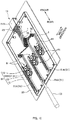
- Fig. 4 is a perspective view of a cleaning tool 10 according to a third embodiment in a state where a cover of a body housing 21A is removed.
- the cleaning tool 10 in the third embodiment is a tool used for cleaning a backplane connector attached to a connector wall (midplane or backplane board) located at the back of a plug-in unit.
- An operator holds an operation lever 32 of the cleaning tool 10, slides a board 33 to which the cleaning tool 10 is attached into a guide groove for a printed board, and presses a cleaning unit 1 against a backplane connector by a head 11 of the cleaning tool 10.
- a plurality of (here, six) connecting end faces (ferrule endfaces) are arranged on the backplane connector.
- the cleaning tool 10 includes a plurality of heads 11 (here, six heads 11, not illustrated) corresponding to the plurality of respective connecting end faces of the backplane connector, and the cleaning unit 1 is supplied to and collected from each of the heads 11.
- the cleaning tool 10 in the third embodiment includes the six heads 11 and six reel units 61.
- the reel units 61 are provided to correspond to the six respective heads 11, and are each a unit for supplying and collecting the cleaning unit 1 in each of the heads 11.
- Each of the reel units 61 includes a supply reel 12 and a take-up reel 13 rotatable about a common rotation shaft 15.
- the supply reel 12 and the take-up reel 13 of each of the reel units 61 are arranged rotatably about the common rotation shaft 15 in the present embodiment.
- an area of the cleaning tool 10 occupied in a plane perpendicular to the rotation shaft 15 can be reduced than that when a rotation shaft of the take-up reel 13 and a rotation shaft of the supply reel 12 of each of the reel units 61 are separately provided, and size reduction of the cleaning tool 10 can be achieved.
- Fig. 5 is a perspective view of each reel unit 61.
- Figs. 6A and 6B are exploded perspective views of the reel unit 61.
- Fig. 6A is an exploded perspective view of the reel unit 61 when seen from a pinion 51B side.
- Fig. 6B is an exploded perspective view of the reel unit 61 when seen from a supply reel 12 side.
- the cleaning tool 10 includes, as a take-up mechanism for taking up the cleaning unit 1, a conversion mechanism 51 and a clutch mechanism (one-way clutch 54).
- the conversion mechanism 51 is constituted by a rack-and-pinion mechanism, and includes a rack 51A and pinions 51B.
- the rack 51A is a linear gear provided on the operation lever 32, and makes a reciprocating motion linearly along the front-rear direction with respect to a tool body 41.
- Each pinion 51B is a circular gear provided on a tool body 41 side.
- the pinion 51B is provided on a transmission wheel 17 and arranged rotatably about the rotation shaft 15 shared by the supply reel 12 and the take-up reel 13.
- a plurality of (here, six) pinions 51B are arranged for one rack 51A.
- rotary motions of the plurality of (here, six) pinions 51B can be generated from a linear motion of one rack 51A.
- the plurality of (here, six) pinions 51B are arranged in series for one rack 51A.
- a clutch mechanism in the third embodiment is constituted by the one-way clutch 54 and a reverse rotation preventing mechanism 55.
- the one-way clutch 54 is a mechanism for transmitting rotary force in one direction only.
- the one-way clutch 54 is constituted by an internal gear ratchet mechanism, and includes a ratchet internal gear 54A provided on the transmission wheel 17 and a pawl member 54B provided on the take-up reel 13.
- the ratchet internal gear 54A is a ratchet provided on an inner circumference of the transmission wheel 17.
- the pawl member 54B includes a pawl part (s) 541B and a spring part (s) 542B.
- the pawl part 541B is a pawl-shaped section (ratchet pawl) inscribed in the ratchet internal gear 54A.
- the spring part 542B is an elastic member that presses the pawl part 541B against the ratchet internal gear 54A and inscribes the pawl part 541B in the ratchet internal gear 54A while allowing displacement of the pawl part 541B.
- Figs. 7A and 7B are explanatory diagrams for illustrating an operation of the one-way clutch 54.
- Figs. 7A and 7B illustrate an internal situation through the transmission wheel, and an internal structure is illustrated by thin lines.
- the reverse rotation preventing mechanism 55 (cf. Fig. 5 ) is provided in order to prevent such a reverse rotation of the take-up reel 13.
- the reverse rotation preventing mechanism 55 may not be needed.
- the reverse rotation preventing mechanism 55 is constituted by a ratchet mechanism, and includes, as illustrated in Fig. 5 , a non-return pawl 55B attached to the body housing 21A and a ratchet wheel 55A (ratchet) provided on the take-up reel 13.
- the reverse rotation preventing mechanism 55 in the third embodiment is constituted by an external gear ratchet mechanism.
- the reverse rotation preventing mechanism 55 is not limited to an internal gear ratchet mechanism as long as the reverse rotation preventing mechanism 55 is a mechanism for preventing a reverse rotation of the take-up reel 13, and may be an external gear ratchet mechanism.
- a rotation preventing mechanism 56 is provided in order to prevent excessive rotation of the supply reel 12 in the third embodiment.
- the rotation preventing mechanism 56 includes engagement teeth 56A provided on an outer ring of the supply reel 12 and a catch pawl 56B that is attached to the body housing 21A and engages with the engagement teeth 56A.
- the rotation preventing mechanism 56 is not limited to this configuration as long as the rotation preventing mechanism 56 is a mechanism capable of preventing excessive rotation of the supply reel 12.
- the cleaning tool 10 in the third embodiment includes, as a take-up mechanism for taking up the cleaning unit 1 to the take-up reel 13, the rack 51A, the transmission wheel 17 including the pinion 51B and the ratchet internal gear 54A, and the take-up reel 13 including the pawl member 54B and the ratchet wheel 55A (ratchet). Also in this embodiment, the transmission wheel 17 (pinion 51B) is supported rotatably by the rotation shaft 15 shared by the supply reel 12 and the take-up reel 13.
- the cleaning tool 10 in the third embodiment includes the plurality of (here, six) take-up reels 13, and the plurality of (here, six) pinions 51B are provided for one rack 51A, and the take-up reels 13 are provided for the respective pinions 51B.
- the used cleaning unit 1 can be taken up to the take-up reel 13 by using the linear motion of the rack 51A in a cleaning operation and rotating each of the take-up reels 13 in the take-up direction.
- Fig. 8 is an enlarged diagram of a vicinity of a head housing 21B.
- the six heads 11 (not illustrated) are housed in the head housing 21B.
- the cleaning unit 1 supplied from and to be collected to each of the reel units 61 is put around a pressing surface of each of the heads 11.
- the head housing 21B is provided with, as guiding sections, 12 openings 23A being a supply port or a collection port of the cleaning unit 1.
- the 12 openings 23A (guiding sections) each restrict a movement range of the cleaning unit 1 in the width direction.
- the 12 openings 23A are formed such that positions in the width direction are aligned. In this way, the openings 23A can keep a position of the cleaning unit 1 in the width direction on the upstream side of the head 11 to be aligned with a position of the cleaning unit 1 in the width direction on the downstream side of the head 11.
- the supply reel 12 and the take-up reel 13 are arranged rotatably about the common rotation shaft 15, a position in which the cleaning unit 1 is supplied from the supply reel 12 and a position in which the cleaning unit 1 is taken up to the take-up reel 13 are different positions in the width direction, but misalignment in the width direction of the cleaning unit 1 put around the pressing surfaces of the heads 11 can be suppressed by providing the cleaning tool 10 with the guiding sections (12 openings 23A of the head housing 21B).
- driven rollers 70 are arranged in a transport path of the cleaning unit 1.
- Each of the driven rollers 70 is a roller provided in the transport path of the cleaning unit 1, and is a roller that leads the cleaning unit 1 while being driven and rotated.
- the driven roller 70 includes a shaft section 71 and a pair of flange sections 72.
- the shaft section 71 is a section that contacts the cleaning unit 1.
- Each of the flange sections 72 is an edge part (flange part) protruding from the shaft section 71 on both ends of the shaft section 71. Detachment of the cleaning unit 1 from the shaft section 71 can be suppressed by providing the flange sections 72 in the driven roller 70.
- the driven roller 70 that transports the cleaning unit 1 in the transport path (supply path) from the supply reel 12 to the head 11 and the driven roller 70 that transports the cleaning unit 1 in the transport path (collection path) from the head 11 to the take-up reel 13 are provided.
- the supply reel 12 and the take-up reel 13 are arranged rotatably about the common rotation shaft 15, a position in which the cleaning unit 1 is supplied from the supply reel 12 and a position in which the cleaning unit 1 is taken up to the take-up reel 13 are different positions in the width direction.
- the driven roller 70 in the supply path transport path in which the cleaning unit 1 is transported from the supply reel 12 to the head 11
- the driven roller 70 in the collection path transport path in which the cleaning unit 1 is transported from the head 11 to the take-up reel 13
- the cleaning unit 1 is transported while a position in the width direction is gradually adjusted (cf. Fig. 8 ).
- the cleaning unit 1 is more likely to be misaligned in the width direction with respect to the driven roller 70 in this embodiment.
- Fig. 9A is an explanatory diagram for illustrating the driven roller 70 according to this embodiment.
- Fig. 9B is an explanatory diagram for illustrating a driven roller 70 according to a comparative example.
- an inner surface of the flange section 72 of the driven roller 70 is a tapered surface having a diameter gradually increased toward the outside in the width direction.
- the driven roller 70 in the supply path transport path in which the cleaning unit 1 is transported from the supply reel 12 to the head 11
- the driven roller 70 in the collection path transport path in which the cleaning unit 1 is transported from the head 11 to the take-up reel 13
- the driven roller 70 in the collection path transport path in which the cleaning unit 1 is transported from the head 11 to the take-up reel 13
- an area of the transport path of the cleaning unit 1 occupied in a plane perpendicular to the rotation shaft of the driven roller 70 can be reduced, and size reduction of the cleaning tool 10 can be achieved.
- the driven roller 70 in the supply path transport path in which the cleaning unit 1 is transported from the supply reel 12 to the head 11
- the driven roller 70 in the collection path transport path in which the cleaning unit 1 is transported from the head 11 to the take-up reel 13
- the cleaning unit 1 in the supply path and the cleaning unit 1 in the collection path are transported while being aligned in the width direction in the supply path and the collection path between the driven roller 70 and the driven roller 70.
- an area of the transport path of the cleaning unit 1 occupied in the plane perpendicular to the rotation shaft of the driven roller 70 can be reduced, and size reduction of the cleaning tool 10 can be achieved.
- the cleaning unit 1 in the supply path and the cleaning unit 1 in the collection path are transported while being aligned in the width direction, and an area of the transport path of the cleaning unit 1 can be reduced, which is particularly advantageous.
- Fig. 10 is a perspective view of a cleaning tool 10 according to a modified example of the third embodiment.
- An operation lever 32 of the cleaning tool 10 in the modified example is attached with three branched racks 51A, and respective pinions 51B of two reel units 61 are arranged for each of the racks 51A.
- the six pinions 51B are arranged in a parallel manner instead of being arranged in series in the cleaning tool 10 in the modified example.
- a used cleaning unit 1 can be taken up to the take-up reel 13 by using a linear motion of the racks 51A in the cleaning operation and rotating each of the take-up reels 13 in the take-up direction.
Abstract
Description
- The present invention relates to a cleaning tool for an optical connector.
- A cleaning tool is known that cleans a connecting end face of an optical connector (endface of a ferrule) . For example,
Patent Literatures 1 and 2 describe a cleaning tool that cleans a bonding endface of an optical connector by pressing a cleaning tape (cleaning unit) wound around a pressing surface of a head against the bonding endface of the optical connector. In the cleaning tool described inPatent Literature 1, by performing a rotation operation on an operation dial, the cleaning tape is taken up to a take-up reel, and the cleaning tape is also supplied from a supply reel. In the cleaning tool described in Patent Literature 2, by using a relative movement of a tool body and an extending section extending from the tool body when a cleaning tool body is moved toward the extending section while a head at a tip of the extending section presses a cleaning unit against an optical connector, the cleaning unit is taken up to a take-up reel by rotation of the take-up reel, and the cleaning tape is also supplied from a supply reel. - It is also known that working efficiency can be increased by simultaneously cleaning endfaces of a plurality of ferrules. In a cleaning tool described in Patent Literature 3, two head members are provided, and endfaces of a plurality of ferrules are cleaned simultaneously. Further, in a cleaning tool described in Patent Literature 4, endfaces of a plurality of ferrules are cleaned simultaneously.
- Note that, Patent Literatures 4 and 5 describe that a board to which the cleaning tool is attached is slid into a guide groove when an optical connector (backplane connector) attached to a backplane board located at the back of a plug-in unit is cleaned (cf.
Fig. 5 in Patent Literature 4, for example). -
- Patent Literature 1:
JP 4870006B - Patent Literature 2:
JP 2014-35489A - Patent Literature 3:
JP 5238873B - Patent Literature 4:
JP 4101486B - Patent Literature 5:
JP 2009-229843A - In the cleaning tool in any of
Patent Literatures 1 to 5, a rotation shaft of the take-up reel and a rotation shaft of the supply reel are separately provided. As a result, an area of the cleaning tool occupied in a plane perpendicular to the rotation shaft tends to be large, and size reduction of the cleaning tool is difficult. - An objective of the present invention is to achieve size reduction of a cleaning tool.
- A main aspect of the invention to achieve the above objective is a cleaning tool for cleaning an optical connector, the cleaning tool including: a head that presses a cleaning unit against the optical connector; a supply reel that supplies the cleaning unit to the head; and a take-up reel that takes up the cleaning unit collected from the head, wherein the supply reel and the take-up reel are arranged rotatably about a common rotation shaft.
- Other features of the invention are made clear by the following description and the drawings.
- With the present invention, it is possible to achieve size reduction of a cleaning tool.
-
-
Fig. 1A is a partial cross-sectional view of acleaning tool 10 according to a first embodiment.Fig. 1B is a partial cross-sectional view of acleaning tool 10 according to a comparative example. -
Fig. 2A is a perspective view of acleaning tool 10 according to a second embodiment.Fig. 2B is a perspective view of thecleaning tool 10 according to the second embodiment in a state where abody housing 21A is removed. -
Figs. 3A and 3B are explanatory diagrams for illustrating an operation in a cleaning operation in the second embodiment, and are also explanatory diagrams for illustrating a take-up mechanism.Fig. 3A is an explanatory diagram for illustrating a situation in a push operation.Fig. 3B is an explanatory diagram for illustrating a situation in a pull operation. -
Fig. 4 is a perspective view of acleaning tool 10 according to a third embodiment in a state where a cover of abody housing 21A is removed. -
Fig. 5 is a perspective view of areel unit 61. -
Figs. 6A and 6B are exploded perspective views of thereel unit 61. -
Figs. 7A and 7B are explanatory diagrams for illustrating an operation of a one-way clutch 54. -
Fig. 8 is an enlarged diagram of a vicinity of ahead housing 21B. -
Fig. 9A is an explanatory diagram for illustrating a drivenroller 70 according to the present embodiment.Fig. 9B is an explanatory diagram for illustrating a drivenroller 70 according to a comparative example. -
Fig. 10 is a perspective view of acleaning tool 10 according to a modified example. - At least the following matters are made clear from the following description and the drawings.
- A cleaning tool for cleaning an optical connector will become clear, the cleaning tool including: a head that presses a cleaning unit against the optical connector; a supply reel that supplies the cleaning unit to the head; and a take-up reel that takes up the cleaning unit collected from the head, wherein the supply reel and the take-up reel are arranged rotatably about a common rotation shaft. With such a cleaning tool, it is possible to reduce an area of the cleaning tool occupied in a plane perpendicular to the rotation shaft and achieve size reduction of the cleaning tool.
- The cleaning tool preferably, further including: a guiding section that keeps a position of the cleaning unit in a width direction on an upstream side of the head to be aligned with a position of the cleaning unit in the width direction on a downstream side of the head. In this way, misalignment in the width direction of the cleaning unit put around a pressing surface of the head can be suppressed. Note that, under circumstances where the supply reel and the take-up reel are arranged rotatably about the common rotation shaft, a position in which the cleaning unit is supplied from the supply reel and a position in which the cleaning unit is taken up to the take-up reel are different positions in the width direction. Thus, providing the guiding section is particularly advantageous.
- Preferably, a driven roller that transports the cleaning unit in a transport path from the supply reel to the guiding section and a driven roller that transports the cleaning unit in a transport path from the guiding section to the take-up reel are arranged rotatably about a common rotation shaft. In this way, size reduction of the cleaning tool can be achieved.
- Preferably, the driven roller includes a shaft section and a pair of flange sections protruding from the shaft section on both ends of the shaft section; and an inner surface of each of the flange sections is a tapered surface having a diameter gradually increased toward the outside in a width direction. In this way, a bend in an edge of the cleaning unit can be suppressed while the cleaning unit is restored to a normal position in the width direction. Note that, when the supply reel and the take-up reel are arranged rotatably about the common rotation shaft, the cleaning unit is more likely to be misaligned in the width direction with respect to the driven roller. Thus, providing the inner surface of the flange section of the driven roller as the tapered surface is particularly advantageous.
- The cleaning tool, preferably further including: a conversion mechanism for converting a linear motion in a cleaning operation to a rotary motion; and a clutch mechanism for rotating the take-up reel in a take-up direction by the rotary motion generated by conversion with the conversion mechanism by restricting a rotation direction of the take-up reel to one direction. In this way, the cleaning unit can be taken up to the take-up reel by using the linear motion in the cleaning operation.
- Preferably, the conversion mechanism includes a rack that makes the linear motion, and a pinion that makes the rotary motion by the linear motion of the rack; and the pinion is arranged rotatably about the common rotation shaft shared by the supply reel and the take-up reel. In this way, size reduction of the cleaning tool can be achieved.
- Preferably, the cleaning tool includes a plurality of the take-up reels; a plurality of the pinions are provided for the rack; and the take-up reels are provided for the respective pinions. In this way, the cleaning unit can be taken up to the plurality of take-up reels by using the linear motion in the cleaning operation.
-
Fig. 1A is a partial cross-sectional view of acleaning tool 10 according to a first embodiment. An upper diagram inFig. 1A is a partial cross-sectional view when seen from a side surface. A lower diagram inFig. 1A is a partial cross-sectional view when seen from an upper surface. - In the following description, as illustrated in
Fig. 1A , a direction in which thecleaning tool 10 is brought close to and away from an optical connector (not illustrated) to be cleaned is a "front-rear direction", an optical connector side when seen from thecleaning tool 10 is "front", and an opposite side is "rear". Note that the front-rear direction is a direction perpendicular to a width direction of acleaning unit 1, and is a direction perpendicular to arotation shaft 15 of a take-up reel 13 and asupply reel 12. - The
cleaning tool 10 is a tool used for cleaning an optical connector. Thecleaning tool 10 includes ahead 11, thesupply reel 12, and the take-up reel 13. - The
head 11 is a member for pressing thecleaning unit 1 against a connecting end face of an optical connector (ferrule endface) (not illustrated) to be cleaned. An endface of thehead 11 is a pressing surface for pressing thecleaning unit 1 against the connecting end face of the optical connector. Thecleaning unit 1 is put around the pressing surface (endface of the head 11). Anunused cleaning unit 1 is supplied from an upstream side of the pressing surface, and a usedcleaning unit 1 is also fed to a downstream side of the pressing surface. - The
supply reel 12 is a reel (cylindrical spool) for supplying thecleaning unit 1. Theunused cleaning unit 1 is previously wound around thesupply reel 12. Thesupply reel 12 is rotatably supported by therotation shaft 15 in ahousing 21. When thecleaning unit 1 is pulled from ahead 11 side, thesupply reel 12 is rotated by tension of thecleaning unit 1, and thecleaning unit 1 is supplied from thesupply reel 12. - The take-
up reel 13 is a reel for taking up thecleaning unit 1. The usedcleaning unit 1 is taken up to the take-up reel 13. The take-up reel 13 is rotatably supported by therotation shaft 15 in thehousing 21. When the take-up reel 13 is rotated, thecleaning unit 1 is taken up to the take-up reel 13. - The
supply reel 12 and the take-up reel 13 are housed in thehousing 21. Thehousing 21 is a member (cover) for housing thesupply reel 12 and the take-up reel 13. Thehousing 21 is provided with therotation shaft 15 that rotatably supports thesupply reel 12 and the take-up reel 13. Therotation shaft 15 is arranged in parallel with the width direction of thecleaning unit 1, and thesupply reel 12 and the take-up reel 13 are aligned in the width direction of thecleaning unit 1 and housed in thehousing 21. - The
housing 21 is provided with a guidingsection 23. The guidingsection 23 is a section for guiding thecleaning unit 1 in the front-rear direction while restricting movement of thecleaning unit 1 in the width direction during transportation. In the present embodiment, the guidingsection 23 is configured to be narrower in the width direction than a section (housing section) for housing thesupply reel 12 and the take-up reel 13. In this way, the guidingsection 23 can keep a position of thecleaning unit 1 in the width direction on the upstream side of thehead 11 to be aligned with a position of thecleaning unit 1 in the width direction on the downstream side of thehead 11. In this embodiment, a position in which thecleaning unit 1 is supplied from thesupply reel 12 and a position in which thecleaning unit 1 is taken up to the take-up reel 13 are different positions in the width direction (because thesupply reel 12 and the take-up reel 13 are arranged rotatably about the common rotation shaft 15), but misalignment of thecleaning unit 1 in the width direction put around the pressing surface of thehead 11 can be suppressed by providing thecleaning tool 10 with the guidingsection 23. - In this embodiment, an
operation dial 31 is provided as a mechanism for rotating the take-up reel 13. Theoperation dial 31 is a disk-shaped section rotating integrally with the take-up reel 13. A part of theoperation dial 31 is exposed from thehousing 21, and operable with a thumb or a finger(s) by an operator. - When an optical connector is cleaned by using the
cleaning tool 10, the operator holds thecleaning tool 10 over thehousing 21, presses thecleaning tool 1 of thehead 11 against the optical connector, and rotates theoperation dial 31 with a thumb in this state. When a rotation operation is performed on theoperation dial 31, the take-up reel 13 is rotated in a take-up direction, which causes the usedcleaning unit 1 to be taken up to the take-up reel 13 and also causes theunused cleaning unit 1 having a length corresponding to a take-up length to be supplied from thesupply reel 12. -
Fig. 1B is a partial cross-sectional view of acleaning tool 10 according to a comparative example. In the comparative example, a rotation shaft of a take-up reel 13 and a rotation shaft of asupply reel 12 are separately provided. As a result, an area of thecleaning tool 10 occupied in a plane perpendicular to the rotation shaft is larger. - On the other hand, the
supply reel 12 and the take-up reel 13 are arranged rotatably about thecommon rotation shaft 15 in this embodiment. In this way, in thecleaning tool 10 in this embodiment, an area of thecleaning tool 10 occupied in the plane perpendicular to therotation shaft 15 can be reduced than that in the comparative example (cf. upper diagram ofFig. 1A ), and size reduction of thecleaning tool 10 can be achieved. -
Fig. 2A is a perspective view of acleaning tool 10 according to a second embodiment.Fig. 2B is a perspective view of thecleaning tool 10 according to the second embodiment in a state where abody housing 21A is removed. - Also in the second embodiment, the
cleaning tool 10 includes ahead 11, asupply reel 12, and a take-up reel 13. Also in the second embodiment, acleaning unit 1 is put around a pressing surface of the head 11 (front endface of the head 11). Anunused cleaning unit 1 is supplied from an upstream side of the pressing surface, and a usedcleaning unit 1 is also fed to a downstream side of the pressing surface. Theunused cleaning unit 1 is wound around thesupply reel 12, and thesupply reel 12 is rotatably supported by arotation shaft 15 of thebody housing 21A. The take-up reel 13 is rotatably supported by therotation shaft 15 of thebody housing 21A. In other words, also in the second embodiment, thesupply reel 12 and the take-up reel 13 are arranged rotatably about thecommon rotation shaft 15. When the take-up reel 13 is rotated, thecleaning unit 1 is taken up to the take-up reel 13. A mechanism for rotating the take-up reel 13 will be described later. - The
cleaning tool 10 in the second embodiment includes atool body 41 and an extendingsection 43. - The
tool body 41 is a member that houses thesupply reel 12 and the take-up reel 13. Thetool body 41 includes thesupply reel 12 and the take-up reel 13, and also includes thebody housing 21A (reel housing, reel cover). Thebody housing 21A is a member that houses thesupply reel 12 and the take-up reel 13. Thebody housing 21A includes therotation shaft 15 that rotatably supports thesupply reel 12 and the take-up reel 13. - The extending
section 43 is a member extending from thetool body 41 toward the front and a member that houses thehead 11. The extendingsection 43 is movable (extendable) in the front-rear direction with respect to thetool body 41. The extendingsection 43 includes thehead 11 and also includes ahead housing 21B. - The
head housing 21B is a member (head cover) that houses thehead 11 while exposing thehead 11 from the front side. Thehead housing 21B is a tubular member. The head 11 (and the cleaning unit 1) is exposed from a front opening of thetubular head housing 21B. A rear opening of thetubular head housing 21B is arranged inside thetool body 41. Through the rear opening of thetubular head housing 21B, theunused cleaning unit 1 is supplied from thesupply reel 12, and the usedcleaning unit 1 is also fed to the take-up reel 13. - The
head housing 21B is provided with a guidingsection 23. The guidingsection 23 is a section for guiding thecleaning unit 1 in the front-rear direction while restricting movement of thecleaning unit 1 in the width direction during transportation. In the second embodiment, a groove part is formed in each of upper and lower surfaces of the guidingsection 23 along the front-rear direction (the groove part in the lower surface is not illustrated), and a movement range of thecleaning unit 1 in the width direction is restricted by transporting thecleaning unit 1 in the groove parts. The groove parts in the upper and lower surfaces of the guidingsection 23 are formed in substantially the same positions in the width direction. In this way, the guidingsection 23 can keep a position of thecleaning unit 1 in the width direction on the upstream side of thehead 11 to be aligned with a position of thecleaning unit 1 in the width direction on the downstream side of thehead 11. Also in the second embodiment, because thesupply reel 12 and the take-up reel 13 are arranged rotatably about thecommon rotation shaft 15, a position in which thecleaning unit 1 is supplied from thesupply reel 12 and a position in which thecleaning unit 1 is taken up to the take-up reel 13 are different positions in the width direction. However, misalignment, in the width direction, of thecleaning unit 1 put around the pressing surface of thehead 11 can be suppressed by providing thecleaning tool 10 with the guidingsection 23. - Note that a spring (not illustrated) is arranged between the guiding
section 23 and thehead 11, and thehead 11 is pressed toward the front with this spring, and the guidingsection 23 guides thehead 11 such that thehead 11 can move back while restricting coming off of thehead 11 from the front. Thus, the guidingsection 23 is also a member that guides thehead 11 in the front-rear direction (a section that guides thehead 11 in the front-rear direction is not illustrated). -
Figs. 3A and 3B are explanatory diagrams for illustrating an operation in a cleaning operation in the second embodiment, and are also explanatory diagrams for illustrating a take-up mechanism.Fig. 3A is an explanatory diagram for illustrating a situation in a push operation.Fig. 3B is an explanatory diagram for illustrating a situation in a pull operation. - When an optical connector (not illustrated) is cleaned by using the
cleaning tool 10, the operator holds thecleaning tool 10 over thebody housing 21A, presses thecleaning tool 1 of thehead 11 against the optical connector, and moves thetool body 41 toward the front in this state (push operation) . At this time, a rear part of the extendingsection 43 gets into thetool body 41. Next, the operator moves thetool body 41 toward the rear to separate thehead 11 from the optical connector (pull operation) . At this time, the extendingsection 43 getting into thetool body 41 returns to the original position by a coil spring (not illustrated) arranged between thetool body 41 and the extendingsection 43. Thetool body 41 and the extendingsection 43 make a relative movement (linear movement) in the front-rear direction by the push operation and the pull operation performed on thecleaning tool 10 by the operator in the cleaning operation. Thecleaning tool 10 in the second embodiment uses this relative movement to rotate the take-up reel 13 in the take-up direction, which causes the usedcleaning unit 1 to be taken up to the take-up reel 13 and also causes theunused cleaning unit 1 having a length corresponding to a take-up length to be supplied from thesupply reel 12. - Next, a take-up mechanism for taking up the
cleaning unit 1 to the take-up reel 13 in the second embodiment will be described. Thecleaning tool 10 includes, as the take-up mechanism for taking up thecleaning unit 1, aconversion mechanism 51 and aclutch mechanism 53. - The
conversion mechanism 51 is a mechanism for converting the relative linear motion of thetool body 41 and the extendingsection 43 to a rotary motion. In the present embodiment, theconversion mechanism 51 is constituted by a rack-and-pinion mechanism, and includes arack 51A and apinion 51B. Therack 51A is a linear gear provided on an extendingsection 43 side, and makes a reciprocating motion linearly along the front-rear direction with respect to the tool body 41 (cf.Figs. 3A and 3B ). Thepinion 51B is a circular gear provided on atool body 41 side. In this embodiment, thepinion 51B is provided on atransmission wheel 17, and thetransmission wheel 17 is arranged rotatably about therotation shaft 15 shared by thesupply reel 12 and the take-up reel 13. When therack 51A makes the reciprocating motion along the front-rear direction, thepinion 51B (transmission wheel 17) makes a reciprocating motion (swing motion) along the rotation direction with therotation shaft 15 as the center (Figs. 3A and 3B ) . - The
clutch mechanism 53 is a mechanism for restricting the rotation direction of the take-up reel 13 to one direction (take-up direction of the cleaning unit 1). In the second embodiment, theclutch mechanism 53 is constituted by afriction transmission mechanism 531 and a reverserotation preventing mechanism 532. - The
friction transmission mechanism 531 is a mechanism for transmitting force by frictional force. In this embodiment, thefriction transmission mechanism 531 includes afriction plate 531A provided on thetransmission wheel 17 and afriction surface 531B provided on the take-up reel 13. - The reverse
rotation preventing mechanism 532 is a mechanism for preventing the take-up reel 13 from rotating in a reverse direction to the take-up direction in which thecleaning unit 1 is taken up. In this embodiment, the reverserotation preventing mechanism 532 is constituted by a ratchet mechanism, and includes anon-return pawl 532B attached to thebody housing 21A of thetool body 41 and aratchet wheel 532A (ratchet) provided on the take-up reel 13. Note that the reverserotation preventing mechanism 532 in this embodiment is constituted by an internal gear ratchet mechanism, but the reverserotation preventing mechanism 532 may be an external gear ratchet mechanism or a mechanism other than the ratchet mechanism as long as the reverserotation preventing mechanism 532 is a mechanism capable of preventing a reverse rotation of the take-up reel 13. - The
cleaning tool 10 in this embodiment includes, as a take-up mechanism for taking up thecleaning unit 1 to the take-up reel 13, therack 51A, thetransmission wheel 17 including thepinion 51B and thefriction plate 531A, and the take-up reel 13 including thefriction surface 531B and theratchet wheel 532A (ratchet) . Then, in this embodiment, the transmission wheel 17 (pinion 51B) is arranged rotatably about therotation shaft 15 shared by thesupply reel 12 and the take-up reel 13. Therotation shaft 15 is shared by thesupply reel 12 and the take-up reel 13, and therotation shaft 15 is also shared by the transmission wheel 17 (pinion 51B), and thus an area of thecleaning tool 10 occupied in the plane perpendicular to therotation shaft 15 can be reduced, and size reduction of thecleaning tool 10 can be achieved. - As illustrated in
Fig. 3A , in the push operation during cleaning, therack 51A of the extendingsection 43 moves toward the rear with respect to thepinion 51B, and the transmission wheel 17 (pinion 51B) rotates counterclockwise inFig. 3A . At this time, a counterclockwise rotation of the take-up reel 13 is restricted by the reverserotation preventing mechanism 532, and thus sliding occurs between thefriction plate 531A and thefriction surface 531B of thefriction transmission mechanism 531. This causes thetransmission wheel 17 to idle, and thus the take-up reel 13 does not rotate. - On the other hand, as illustrated in
Fig. 3B , in the pull operation during cleaning, therack 51A of the extendingsection 43 moves toward the front with respect to thepinion 51B, and the transmission wheel 17 (pinion 51B) rotates clockwise inFig. 3B . The ratchet mechanism allows a clockwise rotation (rotation in the take-up direction) of the take-up reel 13, and thus rotary force of thetransmission wheel 17 is transmitted to the take-up reel 13, and the take-up reel 13 rotates in the take-up direction. In this way, the usedcleaning unit 1 is taken up to the take-up reel 13, and theunused cleaning unit 1 having a length corresponding to a take-up length is also supplied from thesupply reel 12. - Also in the
cleaning tool 10 in the second embodiment described above, thesupply reel 12 and the take-up reel 13 are arranged rotatably about thecommon rotation shaft 15. In this way, also in thecleaning tool 10 in the second embodiment, an area of thecleaning tool 10 occupied in the plane perpendicular to therotation shaft 15 can be reduced, and size reduction of thecleaning tool 10 can be achieved. -
Fig. 4 is a perspective view of acleaning tool 10 according to a third embodiment in a state where a cover of abody housing 21A is removed. - The
cleaning tool 10 in the third embodiment is a tool used for cleaning a backplane connector attached to a connector wall (midplane or backplane board) located at the back of a plug-in unit. An operator holds anoperation lever 32 of thecleaning tool 10, slides aboard 33 to which thecleaning tool 10 is attached into a guide groove for a printed board, and presses acleaning unit 1 against a backplane connector by ahead 11 of thecleaning tool 10. A plurality of (here, six) connecting end faces (ferrule endfaces) are arranged on the backplane connector. Thecleaning tool 10 includes a plurality of heads 11 (here, sixheads 11, not illustrated) corresponding to the plurality of respective connecting end faces of the backplane connector, and thecleaning unit 1 is supplied to and collected from each of theheads 11. - The
cleaning tool 10 in the third embodiment includes the sixheads 11 and sixreel units 61. Thereel units 61 are provided to correspond to the sixrespective heads 11, and are each a unit for supplying and collecting thecleaning unit 1 in each of theheads 11. Each of thereel units 61 includes asupply reel 12 and a take-up reel 13 rotatable about acommon rotation shaft 15. Thesupply reel 12 and the take-up reel 13 of each of thereel units 61 are arranged rotatably about thecommon rotation shaft 15 in the present embodiment. In this way, an area of thecleaning tool 10 occupied in a plane perpendicular to therotation shaft 15 can be reduced than that when a rotation shaft of the take-up reel 13 and a rotation shaft of thesupply reel 12 of each of thereel units 61 are separately provided, and size reduction of thecleaning tool 10 can be achieved. -
Fig. 5 is a perspective view of eachreel unit 61.Figs. 6A and 6B are exploded perspective views of thereel unit 61.Fig. 6A is an exploded perspective view of thereel unit 61 when seen from apinion 51B side.Fig. 6B is an exploded perspective view of thereel unit 61 when seen from asupply reel 12 side. - Also in the third embodiment, the
cleaning tool 10 includes, as a take-up mechanism for taking up thecleaning unit 1, aconversion mechanism 51 and a clutch mechanism (one-way clutch 54). - Also in the third embodiment, the
conversion mechanism 51 is constituted by a rack-and-pinion mechanism, and includes arack 51A and pinions 51B. Therack 51A is a linear gear provided on theoperation lever 32, and makes a reciprocating motion linearly along the front-rear direction with respect to atool body 41. Eachpinion 51B is a circular gear provided on atool body 41 side. Also in the third embodiment, thepinion 51B is provided on atransmission wheel 17 and arranged rotatably about therotation shaft 15 shared by thesupply reel 12 and the take-up reel 13. When therack 51A makes the reciprocating motion along the front-rear direction, thepinion 51B (transmission wheel 17) makes a reciprocating motion (swing motion) along the rotation direction with therotation shaft 15 as the center. - In the third embodiment, a plurality of (here, six)
pinions 51B are arranged for onerack 51A. In this way, rotary motions of the plurality of (here, six)pinions 51B can be generated from a linear motion of onerack 51A. Here, the plurality of (here, six)pinions 51B are arranged in series for onerack 51A. - A clutch mechanism in the third embodiment is constituted by the one-way clutch 54 and a reverse
rotation preventing mechanism 55. - The one-way clutch 54 is a mechanism for transmitting rotary force in one direction only. In this embodiment, the one-way clutch 54 is constituted by an internal gear ratchet mechanism, and includes a ratchet
internal gear 54A provided on thetransmission wheel 17 and apawl member 54B provided on the take-up reel 13. The ratchetinternal gear 54A is a ratchet provided on an inner circumference of thetransmission wheel 17. Thepawl member 54B includes a pawl part (s) 541B and a spring part (s) 542B. Thepawl part 541B is a pawl-shaped section (ratchet pawl) inscribed in the ratchetinternal gear 54A. The spring part 542B is an elastic member that presses thepawl part 541B against the ratchetinternal gear 54A and inscribes thepawl part 541B in the ratchetinternal gear 54A while allowing displacement of thepawl part 541B. -
Figs. 7A and 7B are explanatory diagrams for illustrating an operation of the one-way clutch 54.Figs. 7A and 7B illustrate an internal situation through the transmission wheel, and an internal structure is illustrated by thin lines. - As illustrated in
Fig. 7A , when thetransmission wheel 17 rotates in a predetermined direction (arrow direction inFig. 7A ), the ratchetinternal gear 54A of thetransmission wheel 17 and thepawl part 541B of the take-up reel 13 engage with each other, and thus the one-way clutch 54 transmits rotary force of thepinion 51B to the take-up reel 13. On the other hand, as illustrated inFig. 7B , when thetransmission wheel 17 rotates in a reverse direction (arrow direction inFig. 7B ), thepawl part 541B of the take-up reel 13 does not engage with the ratchetinternal gear 54A of thetransmission wheel 17, and thus the one-way clutch 54 is in a disengaged state. - As illustrated in
Fig. 7B , even in a state where thepawl part 541B of the take-up reel 13 does not engage with the ratchetinternal gear 54A of the transmission wheel 17 (even in a state where the one-way clutch 54 is disengaged), relatively weak force may be transmitted to the take-up reel 13 when thepawl part 541B gets over a tooth of the ratchetinternal gear 54A. As a result, the take-up reel 13 may rotate reversely. Thus, in the third embodiment, the reverse rotation preventing mechanism 55 (cf.Fig. 5 ) is provided in order to prevent such a reverse rotation of the take-up reel 13. However, in a case where rotary force of thetransmission wheel 17 is not transmitted to the take-up reel 13 and the take-up reel 13 does not rotate reversely when the one-way clutch 54 is disengaged (cf.Fig. 7B ), the reverserotation preventing mechanism 55 may not be needed. - Also in the third embodiment, the reverse
rotation preventing mechanism 55 is constituted by a ratchet mechanism, and includes, as illustrated inFig. 5 , anon-return pawl 55B attached to thebody housing 21A and aratchet wheel 55A (ratchet) provided on the take-up reel 13. The reverserotation preventing mechanism 55 in the third embodiment is constituted by an external gear ratchet mechanism. The reverserotation preventing mechanism 55 is not limited to an internal gear ratchet mechanism as long as the reverserotation preventing mechanism 55 is a mechanism for preventing a reverse rotation of the take-up reel 13, and may be an external gear ratchet mechanism. - Note that the
cleaning unit 1 may slacken due to excessive rotation of thesupply reel 12 when thecleaning unit 1 is supplied from thesupply reel 12. Thus, as illustrated inFig. 5 , arotation preventing mechanism 56 is provided in order to prevent excessive rotation of thesupply reel 12 in the third embodiment. Therotation preventing mechanism 56 includesengagement teeth 56A provided on an outer ring of thesupply reel 12 and acatch pawl 56B that is attached to thebody housing 21A and engages with theengagement teeth 56A. Note that therotation preventing mechanism 56 is not limited to this configuration as long as therotation preventing mechanism 56 is a mechanism capable of preventing excessive rotation of thesupply reel 12. - As described above, the
cleaning tool 10 in the third embodiment includes, as a take-up mechanism for taking up thecleaning unit 1 to the take-up reel 13, therack 51A, thetransmission wheel 17 including thepinion 51B and the ratchetinternal gear 54A, and the take-up reel 13 including thepawl member 54B and theratchet wheel 55A (ratchet). Also in this embodiment, the transmission wheel 17 (pinion 51B) is supported rotatably by therotation shaft 15 shared by thesupply reel 12 and the take-up reel 13. - Further, as described above, the
cleaning tool 10 in the third embodiment includes the plurality of (here, six) take-upreels 13, and the plurality of (here, six)pinions 51B are provided for onerack 51A, and the take-upreels 13 are provided for therespective pinions 51B. With such a configuration, the usedcleaning unit 1 can be taken up to the take-up reel 13 by using the linear motion of therack 51A in a cleaning operation and rotating each of the take-upreels 13 in the take-up direction. -
Fig. 8 is an enlarged diagram of a vicinity of ahead housing 21B. - The six heads 11 (not illustrated) are housed in the
head housing 21B. Thecleaning unit 1 supplied from and to be collected to each of thereel units 61 is put around a pressing surface of each of theheads 11. - The
head housing 21B is provided with, as guiding sections, 12openings 23A being a supply port or a collection port of thecleaning unit 1. The 12openings 23A (guiding sections) each restrict a movement range of thecleaning unit 1 in the width direction. In this embodiment, the 12openings 23A are formed such that positions in the width direction are aligned. In this way, theopenings 23A can keep a position of thecleaning unit 1 in the width direction on the upstream side of thehead 11 to be aligned with a position of thecleaning unit 1 in the width direction on the downstream side of thehead 11. Also in this embodiment, because thesupply reel 12 and the take-up reel 13 are arranged rotatably about thecommon rotation shaft 15, a position in which thecleaning unit 1 is supplied from thesupply reel 12 and a position in which thecleaning unit 1 is taken up to the take-up reel 13 are different positions in the width direction, but misalignment in the width direction of thecleaning unit 1 put around the pressing surfaces of theheads 11 can be suppressed by providing thecleaning tool 10 with the guiding sections (12openings 23A of thehead housing 21B). - As illustrated in
Fig. 8 (andFig. 4 ), drivenrollers 70 are arranged in a transport path of thecleaning unit 1. Each of the drivenrollers 70 is a roller provided in the transport path of thecleaning unit 1, and is a roller that leads thecleaning unit 1 while being driven and rotated. The drivenroller 70 includes ashaft section 71 and a pair offlange sections 72. Theshaft section 71 is a section that contacts thecleaning unit 1. Each of theflange sections 72 is an edge part (flange part) protruding from theshaft section 71 on both ends of theshaft section 71. Detachment of thecleaning unit 1 from theshaft section 71 can be suppressed by providing theflange sections 72 in the drivenroller 70. - As illustrated in
Fig. 8 , the drivenroller 70 that transports thecleaning unit 1 in the transport path (supply path) from thesupply reel 12 to thehead 11 and the drivenroller 70 that transports thecleaning unit 1 in the transport path (collection path) from thehead 11 to the take-up reel 13 are provided. In this embodiment, because thesupply reel 12 and the take-up reel 13 are arranged rotatably about thecommon rotation shaft 15, a position in which thecleaning unit 1 is supplied from thesupply reel 12 and a position in which thecleaning unit 1 is taken up to the take-up reel 13 are different positions in the width direction. As a result, the drivenroller 70 in the supply path (transport path in which thecleaning unit 1 is transported from thesupply reel 12 to the head 11) and the drivenroller 70 in the collection path (transport path in which thecleaning unit 1 is transported from thehead 11 to the take-up reel 13) are arranged in different positions in the width direction, and thecleaning unit 1 is transported while a position in the width direction is gradually adjusted (cf.Fig. 8 ). Thus, thecleaning unit 1 is more likely to be misaligned in the width direction with respect to the drivenroller 70 in this embodiment. -
Fig. 9A is an explanatory diagram for illustrating the drivenroller 70 according to this embodiment.Fig. 9B is an explanatory diagram for illustrating a drivenroller 70 according to a comparative example. - In this embodiment, as illustrated in
Fig. 9A , an inner surface of theflange section 72 of the drivenroller 70 is a tapered surface having a diameter gradually increased toward the outside in the width direction. In this way, when thecleaning unit 1 is misaligned in the width direction with respect to the drivenroller 70, a bend in an edge of thecleaning unit 1 can be suppressed while thecleaning unit 1 is restored to a normal position in the width direction. Note that, with an inner surface of theflange section 72 being perpendicular to theshaft section 71 as in the drivenroller 70 in the comparative example illustrated inFig. 9B , when thecleaning unit 1 is misaligned in the width direction with respect to the drivenroller 70, an edge of thecleaning unit 1 is more likely to be bent (thecleaning unit 1 is folded). - In the third embodiment, the driven
roller 70 in the supply path (transport path in which thecleaning unit 1 is transported from thesupply reel 12 to the head 11) and the drivenroller 70 in the collection path (transport path in which thecleaning unit 1 is transported from thehead 11 to the take-up reel 13) are aligned in the width direction of thecleaning unit 1, and arranged rotatably about a common rotation shaft. In this way, in this embodiment, an area of the transport path of thecleaning unit 1 occupied in a plane perpendicular to the rotation shaft of the drivenroller 70 can be reduced, and size reduction of thecleaning tool 10 can be achieved. - Further, in the third embodiment, because the driven
roller 70 in the supply path (transport path in which thecleaning unit 1 is transported from thesupply reel 12 to the head 11) and the drivenroller 70 in the collection path (transport path in which thecleaning unit 1 is transported from thehead 11 to the take-up reel 13) are aligned in the width direction of thecleaning unit 1, thecleaning unit 1 in the supply path and thecleaning unit 1 in the collection path are transported while being aligned in the width direction in the supply path and the collection path between the drivenroller 70 and the drivenroller 70. In this way, an area of the transport path of thecleaning unit 1 occupied in the plane perpendicular to the rotation shaft of the drivenroller 70 can be reduced, and size reduction of thecleaning tool 10 can be achieved. When thecleaning unit 1 is transported between the plurality ofreel units 61 and the plurality ofheads 11 as in the third embodiment, thecleaning unit 1 in the supply path and thecleaning unit 1 in the collection path are transported while being aligned in the width direction, and an area of the transport path of thecleaning unit 1 can be reduced, which is particularly advantageous. -
Fig. 10 is a perspective view of acleaning tool 10 according to a modified example of the third embodiment. - An
operation lever 32 of thecleaning tool 10 in the modified example is attached with three branchedracks 51A, andrespective pinions 51B of tworeel units 61 are arranged for each of theracks 51A. In other words, the sixpinions 51B are arranged in a parallel manner instead of being arranged in series in thecleaning tool 10 in the modified example. Also in such a modified example, a usedcleaning unit 1 can be taken up to the take-up reel 13 by using a linear motion of theracks 51A in the cleaning operation and rotating each of the take-upreels 13 in the take-up direction. - The foregoing embodiments are for facilitating the understanding of the present invention, and are not to be construed as limiting the present invention. The present invention may be modified and/or improved without departing from the gist thereof, and it goes without saying that the present invention encompasses any equivalents thereof.
-
- 1: Cleaning unit;
- 10: Cleaning tool;
- 11: Head;
- 12: Supply reel;
- 13: Take-up reel;
- 15: Rotation shaft;
- 17: Transmission wheel;
- 21: Housing;
- 21A: Body housing;
- 21B: Head housing;
- 23: Guiding section;
- 23A: Opening;
- 31: Operation dial;
- 32: Operation lever;
- 33: Board;
- 41: Tool body;
- 43: Extending section;
- 51: Conversion mechanism (rack-and-pinion mechanism);
- 51A: Rack;
- 51B: Pinion;
- 53: Clutch mechanism;
- 531: Friction transmission mechanism;
- 531A: Friction plate;
- 531B: Friction surface;
- 532: Reverse rotation preventing mechanism (internal gear ratchet mechanism);
- 532A: Ratchet wheel;
- 532B: Non-return pawl;
- 54: One-way clutch (ratchet mechanism);
- 54A: Ratchet internal gear;
- 54B: Pawl member;
- 541B: Pawl part;
- 542B: Spring part;
- 55: Reverse rotation preventing mechanism (external gear ratchet mechanism);
- 55A: Ratchet wheel;
- 55B: Non-return pawl;
- 56: Rotation preventing mechanism;
- 56A: Engagement teeth;
- 56B: Catch pawl;
- 61: Reel unit;
- 70: Driven roller;
- Shaft section;
- Flange section.
Claims (7)
- A cleaning tool for cleaning an optical connector, the cleaning tool comprising:a head that presses a cleaning unit against the optical connector;a supply reel that supplies the cleaning unit to the head; anda take-up reel that takes up the cleaning unit collected from the head, whereinthe supply reel and the take-up reel are arranged rotatably about a common rotation shaft.
- The cleaning tool according to claim 1, further comprising:
a guiding section that keeps a position of the cleaning unit in a width direction on an upstream side of the head to be aligned with a position of the cleaning unit in the width direction on a downstream side of the head. - The cleaning tool according to claim 2, wherein a driven roller that transports the cleaning unit in a transport path from the supply reel to the guiding section and a driven roller that transports the cleaning unit in a transport path from the guiding section to the take-up reel are arranged rotatably about a common rotation shaft.
- The cleaning tool according to claim 3, wherein:the driven roller includes a shaft section and a pair of flange sections protruding from the shaft section on both ends of the shaft section; andan inner surface of each of the flange sections is a tapered surface having a diameter gradually increased toward the outside in a width direction.
- The cleaning tool according to any one of claims 1 to 4, further comprising:a conversion mechanism for converting a linear motion in a cleaning operation to a rotary motion; anda clutch mechanism for rotating the take-up reel in a take-up direction by the rotary motion generated by conversion with the conversion mechanism by restricting a rotation direction of the take-up reel to one direction.
- The cleaning tool according to claim 5, wherein:the conversion mechanism includes a rack that makes the linear motion, and a pinion that makes the rotary motion by the linear motion of the rack; andthe pinion is arranged rotatably about the common rotation shaft shared by the supply reel and the take-up reel.
- The cleaning tool according to claim 6, wherein:the cleaning tool includes a plurality of the take-up reels;a plurality of the pinions are provided for the rack; andthe take-up reels are provided for the respective pinions.
Applications Claiming Priority (2)
| Application Number | Priority Date | Filing Date | Title |
|---|---|---|---|
| JP2017022110A JP6912216B2 (en) | 2017-02-09 | 2017-02-09 | Optical connector cleaning tool |
| PCT/JP2017/046668 WO2018146969A1 (en) | 2017-02-09 | 2017-12-26 | Cleaning device for optical connector |
Publications (2)
| Publication Number | Publication Date |
|---|---|
| EP3561562A1 true EP3561562A1 (en) | 2019-10-30 |
| EP3561562A4 EP3561562A4 (en) | 2020-08-05 |
Family
ID=63107399
Family Applications (1)
| Application Number | Title | Priority Date | Filing Date |
|---|---|---|---|
| EP17895789.0A Withdrawn EP3561562A4 (en) | 2017-02-09 | 2017-12-26 | Cleaning device for optical connector |
Country Status (5)
| Country | Link |
|---|---|
| US (1) | US10802227B2 (en) |
| EP (1) | EP3561562A4 (en) |
| JP (1) | JP6912216B2 (en) |
| CN (1) | CN109906394A (en) |
| WO (1) | WO2018146969A1 (en) |
Families Citing this family (5)
| Publication number | Priority date | Publication date | Assignee | Title |
|---|---|---|---|---|
| JP6889333B2 (en) * | 2019-02-20 | 2021-06-18 | エヌ・ティ・ティ・アドバンステクノロジ株式会社 | Cleaning tool for optical connector |
| JP2020187189A (en) * | 2019-05-10 | 2020-11-19 | 株式会社フジクラ | Cleaning tool and method for manufacturing cleaning tool |
| JP6886997B2 (en) * | 2019-05-10 | 2021-06-16 | 株式会社フジクラ | Cleaning tool |
| CN114040819B (en) * | 2019-10-01 | 2023-05-02 | 株式会社藤仓 | Cleaning tool |
| WO2023234180A1 (en) * | 2022-06-03 | 2023-12-07 | 株式会社フジクラ | Cleaning tool |
Family Cites Families (13)
| Publication number | Priority date | Publication date | Assignee | Title |
|---|---|---|---|---|
| JPS5238873B2 (en) | 1974-02-08 | 1977-10-01 | ||
| JP4101486B2 (en) | 2001-08-07 | 2008-06-18 | 株式会社フジクラ | Optical connector end face cleaning tool |
| JP2003311222A (en) * | 2002-04-18 | 2003-11-05 | Fujikura Ltd | Tool for cleaning optical connector |
| WO2005017590A1 (en) * | 2003-08-13 | 2005-02-24 | Seikoh Giken Co., Ltd. | Optical fiber connector cleaner, and method of cleaning optical fiber connector connection surface |
| JP4870006B2 (en) | 2007-03-28 | 2012-02-08 | 株式会社フジクラ | Optical connector cleaning tool |
| JP5309281B2 (en) | 2008-03-24 | 2013-10-09 | 独立行政法人産業技術総合研究所 | Backplane optical connector cleaning tool |
| JP5238873B2 (en) | 2011-12-05 | 2013-07-17 | 株式会社フジクラ | Optical connector cleaning tool |
| EP2746829B1 (en) | 2012-08-09 | 2019-10-02 | Fujikura Ltd. | Optical connector cleaning tool and optical connector cleaning method |
| JP5439557B2 (en) | 2012-08-09 | 2014-03-12 | 株式会社フジクラ | Optical connector cleaning tool and optical connector cleaning method |
| TWI457629B (en) * | 2013-03-18 | 2014-10-21 | Hobbes & Co Ltd | Cleaning apparatus for optical fiber |
| JP6231440B2 (en) | 2014-06-13 | 2017-11-15 | 株式会社フジクラ | Optical connector cleaning tool |
| JP2016078003A (en) * | 2014-10-21 | 2016-05-16 | 禾普股▲ふん▼有限公司 | Optic fiber connector cleaning tape set |
| US9910227B2 (en) * | 2014-12-11 | 2018-03-06 | Illinois Tool Works Inc. | Oscillating fiber optic cleaning tool |
-
2017
- 2017-02-09 JP JP2017022110A patent/JP6912216B2/en active Active
- 2017-12-26 CN CN201780068180.9A patent/CN109906394A/en active Pending
- 2017-12-26 EP EP17895789.0A patent/EP3561562A4/en not_active Withdrawn
- 2017-12-26 WO PCT/JP2017/046668 patent/WO2018146969A1/en unknown
- 2017-12-26 US US16/464,048 patent/US10802227B2/en active Active
Also Published As
| Publication number | Publication date |
|---|---|
| JP6912216B2 (en) | 2021-08-04 |
| JP2018128598A (en) | 2018-08-16 |
| EP3561562A4 (en) | 2020-08-05 |
| US10802227B2 (en) | 2020-10-13 |
| US20190384012A1 (en) | 2019-12-19 |
| WO2018146969A1 (en) | 2018-08-16 |
| CN109906394A (en) | 2019-06-18 |
Similar Documents
| Publication | Publication Date | Title |
|---|---|---|
| US10802227B2 (en) | Cleaning tool for optical connector | |
| US10634857B2 (en) | Cleaning tool of optical connector | |
| US8397337B2 (en) | Optical connector cleaning tool | |
| JP5419574B2 (en) | Electronic component feeder | |
| EP2746829B1 (en) | Optical connector cleaning tool and optical connector cleaning method | |
| JP5779067B2 (en) | Electronic component feeder | |
| JP4852383B2 (en) | Component supply device, surface mounter, and reel holding method in component supply device | |
| KR20060083919A (en) | Cleaner for an optical fiber connector | |
| US20140259481A1 (en) | Optical connector cleaning tool | |
| JP2014206733A (en) | Cleaner for cleaning optical fiber connector | |
| US20130185883A1 (en) | Optical connector cleaner | |
| US11226454B2 (en) | Cleaning tool for optical connector | |
| JP2018083715A (en) | Sheet sorting device, sheet post-processing device and image formation apparatus | |
| WO2012029196A1 (en) | Optical connector cleaning tool | |
| CN106142936B (en) | Coating film transfer tool | |
| JP2016078003A (en) | Optic fiber connector cleaning tape set | |
| JP2013140221A (en) | Optical connector cleaning tool | |
| JP2009199033A (en) | Cleaner for optical fiber connector, cleaning method of ferrule end surface of optical fiber connector | |
| JP2012232462A (en) | Tape cassette | |
| JP2014154574A (en) | Tape feeder | |
| US20220187545A1 (en) | Cleaning tool and method for manufacturing cleaning tool | |
| JP2020187189A (en) | Cleaning tool and method for manufacturing cleaning tool | |
| KR200486689Y1 (en) | Anti-reversal structure of tape conveying module | |
| CN113753645A (en) | Belt recoiling device | |
| JP2023016161A (en) | Sheet transport device and image formation device |
Legal Events
| Date | Code | Title | Description |
|---|---|---|---|
| STAA | Information on the status of an ep patent application or granted ep patent |
Free format text: STATUS: THE INTERNATIONAL PUBLICATION HAS BEEN MADE |
|
| PUAI | Public reference made under article 153(3) epc to a published international application that has entered the european phase |
Free format text: ORIGINAL CODE: 0009012 |
|
| STAA | Information on the status of an ep patent application or granted ep patent |
Free format text: STATUS: REQUEST FOR EXAMINATION WAS MADE |
|
| 17P | Request for examination filed |
Effective date: 20190722 |
|
| AK | Designated contracting states |
Kind code of ref document: A1 Designated state(s): AL AT BE BG CH CY CZ DE DK EE ES FI FR GB GR HR HU IE IS IT LI LT LU LV MC MK MT NL NO PL PT RO RS SE SI SK SM TR |
|
| AX | Request for extension of the european patent |
Extension state: BA ME |
|
| DAV | Request for validation of the european patent (deleted) | ||
| DAX | Request for extension of the european patent (deleted) | ||
| A4 | Supplementary search report drawn up and despatched |
Effective date: 20200707 |
|
| RIC1 | Information provided on ipc code assigned before grant |
Ipc: B08B 1/00 20060101AFI20200701BHEP Ipc: G02B 6/38 20060101ALI20200701BHEP |
|
| STAA | Information on the status of an ep patent application or granted ep patent |
Free format text: STATUS: EXAMINATION IS IN PROGRESS |
|
| 17Q | First examination report despatched |
Effective date: 20220712 |
|
| STAA | Information on the status of an ep patent application or granted ep patent |
Free format text: STATUS: THE APPLICATION HAS BEEN WITHDRAWN |
|
| 18W | Application withdrawn |
Effective date: 20220825 |