EP3561498B1 - Method for a printed electrochemical gas sensor - Google Patents
Method for a printed electrochemical gas sensor Download PDFInfo
- Publication number
- EP3561498B1 EP3561498B1 EP19168283.0A EP19168283A EP3561498B1 EP 3561498 B1 EP3561498 B1 EP 3561498B1 EP 19168283 A EP19168283 A EP 19168283A EP 3561498 B1 EP3561498 B1 EP 3561498B1
- Authority
- EP
- European Patent Office
- Prior art keywords
- electrodes
- electrolyte
- electrode
- transition layer
- substrate
- Prior art date
- Legal status (The legal status is an assumption and is not a legal conclusion. Google has not performed a legal analysis and makes no representation as to the accuracy of the status listed.)
- Active
Links
Images
Classifications
-
- G—PHYSICS
- G01—MEASURING; TESTING
- G01N—INVESTIGATING OR ANALYSING MATERIALS BY DETERMINING THEIR CHEMICAL OR PHYSICAL PROPERTIES
- G01N27/00—Investigating or analysing materials by the use of electric, electrochemical, or magnetic means
- G01N27/26—Investigating or analysing materials by the use of electric, electrochemical, or magnetic means by investigating electrochemical variables; by using electrolysis or electrophoresis
- G01N27/403—Cells and electrode assemblies
- G01N27/404—Cells with anode, cathode and cell electrolyte on the same side of a permeable membrane which separates them from the sample fluid, e.g. Clark-type oxygen sensors
-
- G—PHYSICS
- G01—MEASURING; TESTING
- G01N—INVESTIGATING OR ANALYSING MATERIALS BY DETERMINING THEIR CHEMICAL OR PHYSICAL PROPERTIES
- G01N27/00—Investigating or analysing materials by the use of electric, electrochemical, or magnetic means
- G01N27/26—Investigating or analysing materials by the use of electric, electrochemical, or magnetic means by investigating electrochemical variables; by using electrolysis or electrophoresis
- G01N27/403—Cells and electrode assemblies
- G01N27/406—Cells and probes with solid electrolytes
- G01N27/407—Cells and probes with solid electrolytes for investigating or analysing gases
- G01N27/4075—Composition or fabrication of the electrodes and coatings thereon, e.g. catalysts
-
- G—PHYSICS
- G01—MEASURING; TESTING
- G01N—INVESTIGATING OR ANALYSING MATERIALS BY DETERMINING THEIR CHEMICAL OR PHYSICAL PROPERTIES
- G01N27/00—Investigating or analysing materials by the use of electric, electrochemical, or magnetic means
- G01N27/26—Investigating or analysing materials by the use of electric, electrochemical, or magnetic means by investigating electrochemical variables; by using electrolysis or electrophoresis
-
- H—ELECTRICITY
- H01—ELECTRIC ELEMENTS
- H01M—PROCESSES OR MEANS, e.g. BATTERIES, FOR THE DIRECT CONVERSION OF CHEMICAL ENERGY INTO ELECTRICAL ENERGY
- H01M4/00—Electrodes
- H01M4/86—Inert electrodes with catalytic activity, e.g. for fuel cells
- H01M4/8663—Selection of inactive substances as ingredients for catalytic active masses, e.g. binders, fillers
- H01M4/8668—Binders
-
- H—ELECTRICITY
- H01—ELECTRIC ELEMENTS
- H01M—PROCESSES OR MEANS, e.g. BATTERIES, FOR THE DIRECT CONVERSION OF CHEMICAL ENERGY INTO ELECTRICAL ENERGY
- H01M4/00—Electrodes
- H01M4/86—Inert electrodes with catalytic activity, e.g. for fuel cells
- H01M4/88—Processes of manufacture
- H01M4/8803—Supports for the deposition of the catalytic active composition
- H01M4/8807—Gas diffusion layers
-
- H—ELECTRICITY
- H01—ELECTRIC ELEMENTS
- H01M—PROCESSES OR MEANS, e.g. BATTERIES, FOR THE DIRECT CONVERSION OF CHEMICAL ENERGY INTO ELECTRICAL ENERGY
- H01M4/00—Electrodes
- H01M4/86—Inert electrodes with catalytic activity, e.g. for fuel cells
- H01M4/88—Processes of manufacture
- H01M4/8825—Methods for deposition of the catalytic active composition
- H01M4/8828—Coating with slurry or ink
-
- H—ELECTRICITY
- H01—ELECTRIC ELEMENTS
- H01M—PROCESSES OR MEANS, e.g. BATTERIES, FOR THE DIRECT CONVERSION OF CHEMICAL ENERGY INTO ELECTRICAL ENERGY
- H01M4/00—Electrodes
- H01M4/86—Inert electrodes with catalytic activity, e.g. for fuel cells
- H01M4/88—Processes of manufacture
- H01M4/8878—Treatment steps after deposition of the catalytic active composition or after shaping of the electrode being free-standing body
- H01M4/8882—Heat treatment, e.g. drying, baking
-
- H—ELECTRICITY
- H01—ELECTRIC ELEMENTS
- H01M—PROCESSES OR MEANS, e.g. BATTERIES, FOR THE DIRECT CONVERSION OF CHEMICAL ENERGY INTO ELECTRICAL ENERGY
- H01M4/00—Electrodes
- H01M4/86—Inert electrodes with catalytic activity, e.g. for fuel cells
- H01M4/90—Selection of catalytic material
- H01M4/92—Metals of platinum group
- H01M4/925—Metals of platinum group supported on carriers, e.g. powder carriers
- H01M4/926—Metals of platinum group supported on carriers, e.g. powder carriers on carbon or graphite
-
- Y—GENERAL TAGGING OF NEW TECHNOLOGICAL DEVELOPMENTS; GENERAL TAGGING OF CROSS-SECTIONAL TECHNOLOGIES SPANNING OVER SEVERAL SECTIONS OF THE IPC; TECHNICAL SUBJECTS COVERED BY FORMER USPC CROSS-REFERENCE ART COLLECTIONS [XRACs] AND DIGESTS
- Y02—TECHNOLOGIES OR APPLICATIONS FOR MITIGATION OR ADAPTATION AGAINST CLIMATE CHANGE
- Y02E—REDUCTION OF GREENHOUSE GAS [GHG] EMISSIONS, RELATED TO ENERGY GENERATION, TRANSMISSION OR DISTRIBUTION
- Y02E60/00—Enabling technologies; Technologies with a potential or indirect contribution to GHG emissions mitigation
- Y02E60/30—Hydrogen technology
- Y02E60/50—Fuel cells
Definitions
- Electrochemical gas sensors are well known for detecting and quantifying toxic gases such as carbon monoxide, oxygen and the like. Such sensors can be implemented using electrochemical cells. Electrochemical sensors traditionally comprise a gas diffusion working (or sensing) electrode, often based on a platinum or graphite/platinum catalyst dispersed on polytetrafluorethylene (PTFE) tape. The target gas is reacted at this electrode while a balancing reaction takes place at the counter electrode.
- the electrodes are contained within an outer housing which contains a liquid electrolyte, such as sulfuric acid.
- the gas typically enters the housing through a controlled diffusion access port, which regulates the ingress of target gas into the cell. The gas reacts at the electrode and affects the electrical output of the sensor.
- US 2014/0311905 relates to a printed gas sensor.
- US 8,840,765 relates to an oxygen sensor with microporous electrolyte layer and partially open cover membrane.
- EP 2950090 relates to an electrochemical gas sensor including a plurality of electrodes at least one of which is formed of a catalyst/binder slurry which is halftone printed onto a substrate, the composite printed element and substrate are sintered to form the electrode.
- component or feature may,” 29 “can,” “could,” “should,” “would,” “preferably,” “possibly,” “typically,” “optionally,” “for example,” “often,” or “might” (or other such language) be included or have a characteristic, that particular component or feature is not required to be included or to have the characteristic. Such component or feature may be optionally included, or it may be excluded.
- Embodiments may reduce electrolyte leakage within an electrochemical sensor and/or improve contact between the electrolyte and a plurality of electrodes.
- the electrodes are formed on a substrate and may contact ambient gas via diffusion holes through the substrate.
- the electrodes in the sensor may participate in electrochemical reactions via contact with the electrolyte, and may also prevent electrolyte leaking from the diffusion holes.
- the electrodes may not be robust enough to prevent electrolyte leakage through the diffusion holes, particularly during high humidity (e.g., more than 95% relative humidity (RH)).
- the preparation of the catalyst paste for forming the electrode(s) may easily introduce moisture into the electrochemical sensor, which may have a negative effect on the printing process, and may lead to the electrodes connecting during the printing formation process (and may result in a short out within the sensor).
- the electrolyte When traditionally printing (or otherwise applying) the electrolyte on the electrode(s), there may be a high rate of failure because the electrode comprises a hydrophobic material, while the electrolyte is hydrophilic. For effective functioning of the electrochemical sensor, the electrolyte must contact the electrode, and in some cases permeate and/or wet the electrode material.
- Embodiments comprise preparing a homogenous catalyst paste for forming an electrode on a substrate which can remove and/or prevent moisture from pervading the electrode and may result in a robust electrode with resistance to leakage through the diffusion holes during high humidity (more than 95% RH). Additionally, embodiments comprise changing the concentration of the mixture of the perfluorinated ion solution and a catalyst (Pt, Au, Ru, Ir, Ag powder, carbon black, graphite, and/or a combination thereof) and solve the problem of leakage from the diffusion holes during high humidity.
- a catalyst Pt, Au, Ru, Ir, Ag powder, carbon black, graphite, and/or a combination thereof
- embodiments comprise printing a transition layer between the electrodes and the electrolyte, where the transition layer may facilitate contact between the electrodes and the electrolyte.
- the transition layer comprises a thin, hydrophilic material. The transition layer is applied to the electrodes before the electrolyte is applied to the electrodes.
- a perfluorinated ion solution (e.g., GEFC, 5 wt% in DMF, Golden Energy Fuel Cell Co., Ltd.) is used as a binder in a catalyst paste which is printed onto a substrate to form electrodes through annealing.
- the method comprises mixing the perfluorinated ion solution with a catalyst (e.g., Pt, Au, Ru, Ir, Ag powder, carbon black, graphite, and/or a combination thereof). Then, the mixture is concentrated to make a paste with a suitable viscosity for printing.
- the paste is printed on to a substrate comprising diffusion holes to form electrodes through annealing. The diffusion holes are formed into the substrate and extend through the substrate thickness.
- the mixing process and/or printing process may be performed in an open system where the mixture may be exposed to an ambient environment, which may allow moisture from the ambient air to penetrate the electrodes and/or other elements of the sensor during printing.
- the mixing process and optionally the printing process are completed under a vacuum, to prevent moisture and/or other substances from the ambient environment from penetrating the materials of the layers of the electrochemical sensor.
- concentrating of the perfluorinated ion solution and subsequent mixing with a catalyst are combined into a single step. These processes are completed using ultrasonication to generate a slurry made of the perfluorinated ion solution and catalyst powder in a homogenous suspension. Additionally, the preparation is performed by vacuum distillation in a relatively closed system with negative-pressure condition. In particular, the process conditions are approximately 200-300 Pa (2-3 mbar) and approximately 40-50°C. The viscosity of the mixture may be controlled by monitoring the rotation speed of a magnetic stirrer.
- the lower temperature (e.g., 40-50°C) of the method may not cause undesirable binding of the perfluorinated ion solution. Additionally, the concentrating process may produce more interaction between the perfluorinated ion solution binder and the catalyst particles than traditional simple mixing of concentrated perfluorinated ion solution and catalyst powder, where the interaction contributes to the strength and robustness of the electrodes and may prevent electrolyte leakage in the final sensor.
- the method facilitates the printing of a hydrophilic electrolyte onto hydrophobic electrodes.
- the method comprises printing a transition layer onto the electrodes before applying an electrolyte.
- the transition layer comprises a water-immiscible solvent and a hydrophilic, inert powder.
- the added transition layer may not significantly thicken the electrode(s), because the same stencil and/or template may be used during printing of the electrode and printing of the transition layer, and the printed hydrophilic particles of the transition layer may disperse or otherwise fit into holes and/or spaces created on the surface of the electrodes by the catalyst of the electrodes.
- the surface of the electrodes may become more hydrophilic, and the electrolyte can be more easily printed onto the electrodes.
- the transition layer may be thin enough to not interfere with interaction between the electrodes and the electrolyte.
- the transition layer may comprise conductive properties configured to allow for electric communication between the electrodes and the electrolyte.
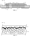
- an ultrathin electrochemical (EC) sensor 100 is made by printing technology.
- the sensor 100 comprises electrodes 106, 108 and 110, an electrolyte 112 (wherein the electrolyte typically contacts and provides electrical interaction between all the electrodes), and optionally an encapsulation layer 114, which may be printed layer by layer onto a substrate 102.
- the substrate 102 comprises a plurality of diffusion holes 104, wherein the electrodes 106, 108, and 110 are printed over the diffusion holes 104 (for example, with each electrode having at least one diffusion hole underlying it).
- the diffusion holes 104 may comprise a size, shape, a first diameter, a second diameter, and/or length that causes a capillary effect within the diffusion holes 104.
- the electrolyte 112 may be printed or otherwise applied over the electrodes 106, 108, and 110.
- the electrodes may comprise a sensing electrode 106, a reference electrode 108, and a counter electrode 110.
- the encapsulation layer 114 can be used to seal the electrolyte 112 (e.g. creating an envelope applied to the substrates which seals the electrolyte and underlying electrodes).
- the encapsulation layer 114 can comprise any material suitable for bonding to the substrate 102 and retaining the electrolyte 112 in position on the substrate 102. Any of the materials described herein can be used for the encapsulation layer 114. Additional materials such as silicone rubber or other polymeric materials can also be used as the encapsulation layer 114.
- the encapsulation layer 114 may comprise a silicon or silicone material.
- the encapsulation layer 114 may serve as a water vapor diffusion barrier to seal the electrolyte 112 from the external environment.
- the encapsulation layer 114 may be flexible to allow the volume of the electrolyte 112 to change over time, for example, in response to a gain or loss of water in a hygroscopic electrolyte.
- a solution of perfluorinated ion electrolyte solution (GEFC-IES the copolymer of perfluorosulfonic acid and PTFE) commercially available from Golden Energy Fuel Cell Co., Ltd. or Nafion ® (copolymer of tetrafluoroethylene (Teflon ® ) and perfluoro-3,6-dioxa-4-methyl-7-octene-sulfonic acid) commercially available from DupontTM, is used as a binder.
- the catalyst (as described above) may be Pt, Au, Ru, Ir, Ag powder, carbon black, graphite, and/or a combination thereof.
- Glycol or other similar chemicals can be used as a diluent to form a catalyst slurry, recipe or catalyst system, which can be printed on a PTFE membrane by a printer.
- the printed element is sintered at an elevated temperature to form an electrode which can be used in an electrochemical sensor.
- the sensing electrode 106, the reference electrode 108, and the counter electrode 110 can be arranged in a co-planar, non-overlapping arrangement on the surface of the substrate 102. While shown in FIG. 1 as having three electrodes, the sensor 100 can also be used with only two electrodes, for example including the sensing electrode 106 and the counter electrode 110. Four or more electrodes may also be present. For example, two or more sensing electrodes can be present and each sensing electrode may operate at a different potential to enable the detection of more than one target gas. Alternatively, four or more electrodes may be present to enable diagnostic tests to be conducted during operation of the sensor 100, continuously, periodically, or aperiodically. In some contexts, the sensing electrode 106 may also be referred to as a working electrode.
- composition, size, and configuration of the electrodes 106, 108, 110 can depend on the specific species of target gas or gasses being detected by the sensor 100.
- One or more (or all) of the electrodes 106, 108, 110 can comprise a porous, gas permeable membrane.
- the electrode e.g., the sensing electrode 106
- the electrode may be placed over the aperture or capillary (which may also be called a diffusion hole 104).
- the gas diffusing through the capillary 104 may then contact and diffuse through the permeable membrane to react with the electrolyte 112 at the opposite surface of the electrode.
- Such an electrode can be formed of any of the materials described herein.
- various hydrophobic components such as PTFE can be combined with the electrode material and/or used as a backing layer ( e.g., as a tape or support) for the electrode on the substrate 102.
- sensing electrode 106 can comprise a catalyst such as platinum or carbon, supported on a PTFE membrane.
- the counter electrode 110 may comprise a catalyst mounted on a PTFE backing tape, in the same manner as the gas sensing electrode 106.
- the electrodes comprise hydrophobic materials.
- Various coatings such as PTFE coatings can be used to provide a hydrophobic surface while maintaining a degree of porosity for gas diffusion of the target gas.
- the electrode material can be formed to exhibit hydrophobicity or super-hydrophobicity.
- the electrode material can be formed using a template material to form a patterned surface for the electrode, where the pattern may impart hydrophobic properties to the electrode.
- the patterning material can include any suitable material that can be removed once the electrode is formed.
- Nanosized polymer spheres e.g., nanosized latex spheres-which are commercially available
- a suitable sacrificial substrate e.g., a metal such as copper.
- Electrodes can then be electroplated around the assembled spheres to produce a suitable hydrophobic surface.
- the resulting electrode surface may also have porosity for gas diffusibility.
- Plating bath additives may be added as appropriate.
- other templating techniques such as self-assembled surfactant molecules can be used.
- the templating material can then be subsequently removed, for example by dissolution, heat, or the like.
- the resulting electrode material can then be used for one or more of the electrodes 106, 108, 110 while exhibiting hydrophobic properties. Electrodes may be formed using one or more of the methods/processes described herein.
- the electrodes 106, 108, 110 may be at least partially covered by or in contact with the electrolyte 112 (and typically might all be entirely covered by the electrolyte. Electrical contact can be made with an external contact lead through one or more electrical conductors such as wires 116.
- the wires 116 can comprise foils, wires, or deposited materials on the substrate 102.
- the electrical conductors may comprise noble metals ( e.g., platinum), such as by being formed from noble metals or coated with noble metals if the conductors are in contact with the electrolyte 112. The electrical conductors may not be formed from noble metals if the electrical conductors are not in contact with the electrolyte 112.
- the electrolyte 112 may comprise any material capable of providing an electrically conductive pathway between the electrodes 106, 108, 110.
- the electrolyte 112 may be non-reactive with the substrate 102 material. If the electrolyte 112 and the substrate 102 can react, an insulting, non-reactive layer may be placed over the substrate prior to disposition of the electrodes 106, 108, 110 and the electrolyte 112.
- the electrolyte 112 can comprise a liquid electrolyte, a gelled electrolyte, a solid electrolyte, or the like.
- the electrolyte 112 can be contained in or retained by a porous or absorbent material.
- the electrolyte 112 comprises an aqueous electrolyte in particular a solution of acid.
- the electrolyte can comprise a hygroscopic acid such as sulfuric acid for use in an oxygen sensor.
- the electrolyte can comprise sulfuric acid having a molar concentration between about 3 M to about 10 M. Since sulfuric acid is hygroscopic, the concentration can vary from about 10 to about 70 wt% (1 to 11.5 molar) over a relative humidity (RH) range of the environment of about 3 to about 95%.
- ionic liquid electrolytes can also be used to detect certain gases.
- the ionic liquids may have a greater viscosity than a corresponding aqueous electrolyte.
- a viscosifier may be added to provide an increased viscosity, which may aid in retaining the electrolyte in contact with the electrolytes.
- the electrolyte can be present in the form of a gel or a semi-solid.
- the electrolyte 112 can comprise a solid electrolyte.
- Solid electrolytes can include electrolytes adsorbed or absorbed into a solid structure such as a solid porous material and/or materials that allow protonic and or electronic conduction as formed.
- the solid electrolyte can be a protonic conductive electrolyte membrane.
- the solid electrolyte can be a perfluorinated ionexchange polymer such as Nafion or a protonic conductive polymer such as poly(ethylene glycol), poly(ethylene oxide), poly(propylene carbonate).
- Nafion is a hydrated copolymer of polytretafluoroethylene and polysulfonyl fluoride vinyl ether containing pendant sulfuric acid groups.
- a Nafion membrane When used, a Nafion membrane can optionally be treated with an acid such as H3PQ4, sulfuric acid, or the like, which improves the moisture retention characteristics of Nafion and the conductivity of hydrogen ions through the Nafion membrane.
- the sensing, counter and reference electrodes can be hot-pressed onto the Nafion membrane to provide a high conductivity between the electrodes and the solid electrolyte.
- the electrolyte 112 can be disposed on the substrate 102 as a drop or in a solid form so that the electrolyte is in electrical contact with the electrodes 106, 108, 110.
- the electrochemical sensor 100 also comprises a transition layer 120 positioned between the hydrophobic electrode(s) 106 (which may be similar to those described in FIG. 1 ) and the electrolyte 112.
- Electrode 106, 108 and/or 110 formed using a method as described herein may comprise increased hydrophobic characteristics when compared to traditional electrodes. In this case, the possibility of issues when applying the electrolyte to the electrode(s) may be increased as well. Therefore, a transition layer 120 is applied between the electrode(s) and electrolyte to allow contact between the two.
- the sensing electrode 106 is shown, but the transition layer 120 may be applied to any or all of the electrodes 106, 108, and 110 (e.g. of FIG. 1 ).
- the transition layer 120 facilitates contact between the electrode(s) 106 and the electrolyte 112.
- the transition layer 120 comprises a thin, hydrophilic material. The transition layer 120 is applied to the electrode 106 before the electrolyte 112 is applied to the electrode 106.
- the transition layer 120 comprises a water-immiscible solvent and a hydrophilic, inert powder.
- the transition layer 120 may comprise a perfluorinated ion solution and an inert silicon dioxide (SiO 2 ) powder.
- the hydrophilic particles of the transition layer 120 may dispense into spaces fabricated by the catalyst of the electrode(s) 106, wherein the electrode(s) 106 may comprise approximately spherical material in the example shown in FIG. 2 .
- a top surface of the electrode(s) 106 may become more hydrophilic, and the electrolyte 112 can be more easily printed onto (e.g. atop) the electrode(s) 106 (e.g. on the surface opposite that contacting the substrate).
- the transition layer 120 may be thin enough to not interfere with interaction between the electrode(s) 106 and the electrolyte 112.
- the method may comprise mixing approximately 19 grams (g) of perfluorinated ion solution (e.g., 5 wt% GEFC) and approximately 5 g of catalyst (e.g. one of the catalyst materials described above) to obtain a slurry.
- the slurry is treated with ultrasonication, e.g., for approximately 10-15 minutes, where the slurry is mixed under vacuum distillation.
- the temperature may be controlled to be approximately 50°C, and the pressure is approximately 200-300 Pa (2-3 mbar).
- the rotation speed of a magnetic stirrer may be set to approximately 500 rpm. As the mixture thickness, the rotation speed may decrease due to the increased thickness.
- the paste is printed onto a substrate to form the electrode(s).
- a stencil may be placed onto and/or above the substrate, and the paste may be applied over the stencil to form the electrode(s).
- the paste may be applied under a vacuum (as described above).
- the paste is applied over diffusion holes that extends through the substrate.
- Forming the transition layer may comprise mixing approximately 4 g of perfluorinated ion solution (15 wt% GEFC) and approximately 4 g of inert SiO2 powder (e.g., AEROSIL ® 200).
- the mixture may comprise 1 part perfluorinated ion solution to 1 part inert powder.
- the mixture may be rested until bubbles disappear.
- the mixture may be printed to form the transition layer with the same stencil as that used in printing the electrode onto the substrate.
- the transition layer may be heated at approximately 40-50°C for approximately 10 to 15 minutes. The heating temperature and time may be determined to maintain the hydrophilicity of the transition layer.
- the electrolyte may be applied (e.g., printed) onto the electrode(s) comprising the transition layer. This method of forming a transition layer may also be used on electrodes formed using the above method of forming electrodes.
Landscapes
- Chemical & Material Sciences (AREA)
- Electrochemistry (AREA)
- Chemical Kinetics & Catalysis (AREA)
- Life Sciences & Earth Sciences (AREA)
- Health & Medical Sciences (AREA)
- General Chemical & Material Sciences (AREA)
- Engineering & Computer Science (AREA)
- Physics & Mathematics (AREA)
- Manufacturing & Machinery (AREA)
- Pathology (AREA)
- General Physics & Mathematics (AREA)
- Immunology (AREA)
- General Health & Medical Sciences (AREA)
- Biochemistry (AREA)
- Analytical Chemistry (AREA)
- Molecular Biology (AREA)
- Materials Engineering (AREA)
- Thermal Sciences (AREA)
- Measuring Oxygen Concentration In Cells (AREA)
- Inert Electrodes (AREA)
Description
- Electrochemical gas sensors are well known for detecting and quantifying toxic gases such as carbon monoxide, oxygen and the like. Such sensors can be implemented using electrochemical cells. Electrochemical sensors traditionally comprise a gas diffusion working (or sensing) electrode, often based on a platinum or graphite/platinum catalyst dispersed on polytetrafluorethylene (PTFE) tape. The target gas is reacted at this electrode while a balancing reaction takes place at the counter electrode. The electrodes are contained within an outer housing which contains a liquid electrolyte, such as sulfuric acid. The gas typically enters the housing through a controlled diffusion access port, which regulates the ingress of target gas into the cell. The gas reacts at the electrode and affects the electrical output of the sensor.
-
US 2014/0311905 relates to a printed gas sensor.US 8,840,765 relates to an oxygen sensor with microporous electrolyte layer and partially open cover membrane.EP 2950090 relates to an electrochemical gas sensor including a plurality of electrodes at least one of which is formed of a catalyst/binder slurry which is halftone printed onto a substrate, the composite printed element and substrate are sintered to form the electrode. - The invention is defined by the appended claims.
- These and other features will be more clearly understood from the following detailed description taken in conjunction with the accompanying drawings and claims.
- For a more complete understanding of the present invention, reference is now made to the following brief description, taken in connection with the accompanying drawings and detailed description, wherein like reference numerals represent like parts.
-
FIG. 1 illustrates a cross-sectional view of an electrochemical sensor produced according to the method of the present invention. -
FIG. 2 illustrates a detailed cross-sectional view of an electrochemical sensor produced according to the method of the present invention. - It should be understood at the outset that although illustrative implementations of one or more embodiments are illustrated below, the disclosed systems and methods may be implemented using any number of techniques, whether currently known or not yet in existence. The invention should in no way be limited to the illustrative implementations, drawings, and techniques illustrated below, but may be modified within the scope of the appended claims.
- The following brief definition of terms shall apply throughout the application:
- The term "comprising" means including but not limited to, and should be interpreted in the manner it is typically used in the patent context;
- The phrases "in one embodiment," "according to one embodiment," and the like generally mean that the particular feature, structure, or characteristic following the phrase may be included in at least one embodiment of the present invention, and may be included in more than one embodiment of the present invention (importantly, such phrases do not necessarily refer to the same embodiment);
- If the specification describes something as "exemplary" or an "example," it should be understood that refers to a non-exclusive example;
- The terms "about" or "approximately" or the like, when used with a number, may mean that specific number, or alternatively, a range in proximity to the specific number, as understood by persons of skill in the art field (for example ±10%); and
- If the specification states a component or feature "may," 29 "can," "could," "should," "would," "preferably," "possibly," "typically," "optionally," "for example," "often," or "might" (or other such language) be included or have a characteristic, that particular component or feature is not required to be included or to have the characteristic. Such component or feature may be optionally included, or it may be excluded.
- Embodiments may reduce electrolyte leakage within an electrochemical sensor and/or improve contact between the electrolyte and a plurality of electrodes. The electrodes are formed on a substrate and may contact ambient gas via diffusion holes through the substrate. The electrodes in the sensor may participate in electrochemical reactions via contact with the electrolyte, and may also prevent electrolyte leaking from the diffusion holes. However, in some electrochemical sensors, the electrodes may not be robust enough to prevent electrolyte leakage through the diffusion holes, particularly during high humidity (e.g., more than 95% relative humidity (RH)). Meanwhile, the preparation of the catalyst paste for forming the electrode(s) may easily introduce moisture into the electrochemical sensor, which may have a negative effect on the printing process, and may lead to the electrodes connecting during the printing formation process (and may result in a short out within the sensor).
- When traditionally printing (or otherwise applying) the electrolyte on the electrode(s), there may be a high rate of failure because the electrode comprises a hydrophobic material, while the electrolyte is hydrophilic. For effective functioning of the electrochemical sensor, the electrolyte must contact the electrode, and in some cases permeate and/or wet the electrode material.
- Embodiments comprise preparing a homogenous catalyst paste for forming an electrode on a substrate which can remove and/or prevent moisture from pervading the electrode and may result in a robust electrode with resistance to leakage through the diffusion holes during high humidity (more than 95% RH). Additionally, embodiments comprise changing the concentration of the mixture of the perfluorinated ion solution and a catalyst (Pt, Au, Ru, Ir, Ag powder, carbon black, graphite, and/or a combination thereof) and solve the problem of leakage from the diffusion holes during high humidity.
- Additionally, embodiments comprise printing a transition layer between the electrodes and the electrolyte, where the transition layer may facilitate contact between the electrodes and the electrolyte. The transition layer comprises a thin, hydrophilic material. The transition layer is applied to the electrodes before the electrolyte is applied to the electrodes.
- In embodiments, a perfluorinated ion solution (e.g., GEFC, 5 wt% in DMF, Golden Energy Fuel Cell Co., Ltd.) is used as a binder in a catalyst paste which is printed onto a substrate to form electrodes through annealing. The method comprises mixing the perfluorinated ion solution with a catalyst (e.g., Pt, Au, Ru, Ir, Ag powder, carbon black, graphite, and/or a combination thereof). Then, the mixture is concentrated to make a paste with a suitable viscosity for printing. The paste is printed on to a substrate comprising diffusion holes to form electrodes through annealing. The diffusion holes are formed into the substrate and extend through the substrate thickness.
- Typically, the mixing process and/or printing process may be performed in an open system where the mixture may be exposed to an ambient environment, which may allow moisture from the ambient air to penetrate the electrodes and/or other elements of the sensor during printing. The mixing process and optionally the printing process are completed under a vacuum, to prevent moisture and/or other substances from the ambient environment from penetrating the materials of the layers of the electrochemical sensor.
- In the method of the present invention, concentrating of the perfluorinated ion solution and subsequent mixing with a catalyst are combined into a single step. These processes are completed using ultrasonication to generate a slurry made of the perfluorinated ion solution and catalyst powder in a homogenous suspension. Additionally, the preparation is performed by vacuum distillation in a relatively closed system with negative-pressure condition. In particular, the process conditions are approximately 200-300 Pa (2-3 mbar) and approximately 40-50°C. The viscosity of the mixture may be controlled by monitoring the rotation speed of a magnetic stirrer.
- The lower temperature (e.g., 40-50°C) of the method may not cause undesirable binding of the perfluorinated ion solution. Additionally, the concentrating process may produce more interaction between the perfluorinated ion solution binder and the catalyst particles than traditional simple mixing of concentrated perfluorinated ion solution and catalyst powder, where the interaction contributes to the strength and robustness of the electrodes and may prevent electrolyte leakage in the final sensor.
- The method facilitates the printing of a hydrophilic electrolyte onto hydrophobic electrodes. The method comprises printing a transition layer onto the electrodes before applying an electrolyte. The transition layer comprises a water-immiscible solvent and a hydrophilic, inert powder. The added transition layer may not significantly thicken the electrode(s), because the same stencil and/or template may be used during printing of the electrode and printing of the transition layer, and the printed hydrophilic particles of the transition layer may disperse or otherwise fit into holes and/or spaces created on the surface of the electrodes by the catalyst of the electrodes. In some embodiments, there may be substantially no change in the thickness of the electrode due to adding of the transition layer. With the transition layer in place on the surface of the electrode (opposite the substrate and/or direct towards the electrolyte), the surface of the electrodes may become more hydrophilic, and the electrolyte can be more easily printed onto the electrodes. The transition layer may be thin enough to not interfere with interaction between the electrodes and the electrolyte. In some embodiments, the transition layer may comprise conductive properties configured to allow for electric communication between the electrodes and the electrolyte.
- Referring to
FIG. 1 , an ultrathin electrochemical (EC)sensor 100 is made by printing technology. Thesensor 100 compriseselectrodes encapsulation layer 114, which may be printed layer by layer onto asubstrate 102. Thesubstrate 102 comprises a plurality ofdiffusion holes 104, wherein theelectrodes diffusion holes 104 may comprise a size, shape, a first diameter, a second diameter, and/or length that causes a capillary effect within thediffusion holes 104. Theelectrolyte 112 may be printed or otherwise applied over theelectrodes sensing electrode 106, areference electrode 108, and acounter electrode 110. - The
encapsulation layer 114 can be used to seal the electrolyte 112 (e.g. creating an envelope applied to the substrates which seals the electrolyte and underlying electrodes). Theencapsulation layer 114 can comprise any material suitable for bonding to thesubstrate 102 and retaining theelectrolyte 112 in position on thesubstrate 102. Any of the materials described herein can be used for theencapsulation layer 114. Additional materials such as silicone rubber or other polymeric materials can also be used as theencapsulation layer 114. Theencapsulation layer 114 may comprise a silicon or silicone material. Once disposed over the electrolyte 112 (e.g., a liquid electrolyte, a gelled electrolyte, and/or a solid electrolyte), theencapsulation layer 114 may serve as a water vapor diffusion barrier to seal theelectrolyte 112 from the external environment. Theencapsulation layer 114 may be flexible to allow the volume of theelectrolyte 112 to change over time, for example, in response to a gain or loss of water in a hygroscopic electrolyte. - A solution of perfluorinated ion electrolyte solution (GEFC-IES the copolymer of perfluorosulfonic acid and PTFE) commercially available from Golden Energy Fuel Cell Co., Ltd. or Nafion® (copolymer of tetrafluoroethylene (Teflon®) and perfluoro-3,6-dioxa-4-methyl-7-octene-sulfonic acid) commercially available from DupontTM, is used as a binder. The catalyst (as described above) may be Pt, Au, Ru, Ir, Ag powder, carbon black, graphite, and/or a combination thereof. Glycol or other similar chemicals can be used as a diluent to form a catalyst slurry, recipe or catalyst system, which can be printed on a PTFE membrane by a printer. The printed element is sintered at an elevated temperature to form an electrode which can be used in an electrochemical sensor.
- The
sensing electrode 106, thereference electrode 108, and thecounter electrode 110 can be arranged in a co-planar, non-overlapping arrangement on the surface of thesubstrate 102. While shown inFIG. 1 as having three electrodes, thesensor 100 can also be used with only two electrodes, for example including thesensing electrode 106 and thecounter electrode 110. Four or more electrodes may also be present. For example, two or more sensing electrodes can be present and each sensing electrode may operate at a different potential to enable the detection of more than one target gas. Alternatively, four or more electrodes may be present to enable diagnostic tests to be conducted during operation of thesensor 100, continuously, periodically, or aperiodically. In some contexts, thesensing electrode 106 may also be referred to as a working electrode. - The composition, size, and configuration of the
electrodes sensor 100. - One or more (or all) of the
electrodes electrolyte 112 at the opposite surface of the electrode. Such an electrode can be formed of any of the materials described herein. In addition to any of the materials for forming the electrode, various hydrophobic components such as PTFE can be combined with the electrode material and/or used as a backing layer ( e.g., as a tape or support) for the electrode on thesubstrate 102. For example, sensingelectrode 106 can comprise a catalyst such as platinum or carbon, supported on a PTFE membrane. Such as toxic gas sensors, thecounter electrode 110 may comprise a catalyst mounted on a PTFE backing tape, in the same manner as thegas sensing electrode 106. - The electrodes comprise hydrophobic materials. Various coatings such as PTFE coatings can be used to provide a hydrophobic surface while maintaining a degree of porosity for gas diffusion of the target gas. The electrode material can be formed to exhibit hydrophobicity or super-hydrophobicity. The electrode material can be formed using a template material to form a patterned surface for the electrode, where the pattern may impart hydrophobic properties to the electrode. The patterning material can include any suitable material that can be removed once the electrode is formed. Nanosized polymer spheres (e.g., nanosized latex spheres-which are commercially available) can be arranged on a suitable sacrificial substrate (e.g., a metal such as copper). The electrode metal can then be electroplated around the assembled spheres to produce a suitable hydrophobic surface. The resulting electrode surface may also have porosity for gas diffusibility. Plating bath additives may be added as appropriate. Alternatively, other templating techniques such as self-assembled surfactant molecules can be used. The templating material can then be subsequently removed, for example by dissolution, heat, or the like. The resulting electrode material can then be used for one or more of the
electrodes - The
electrodes wires 116. Thewires 116 can comprise foils, wires, or deposited materials on thesubstrate 102. The electrical conductors may comprise noble metals ( e.g., platinum), such as by being formed from noble metals or coated with noble metals if the conductors are in contact with theelectrolyte 112. The electrical conductors may not be formed from noble metals if the electrical conductors are not in contact with theelectrolyte 112. - The
electrolyte 112 may comprise any material capable of providing an electrically conductive pathway between theelectrodes electrolyte 112 may be non-reactive with thesubstrate 102 material. If theelectrolyte 112 and thesubstrate 102 can react, an insulting, non-reactive layer may be placed over the substrate prior to disposition of theelectrodes electrolyte 112. Theelectrolyte 112 can comprise a liquid electrolyte, a gelled electrolyte, a solid electrolyte, or the like. Theelectrolyte 112 can be contained in or retained by a porous or absorbent material. - In an embodiment, the
electrolyte 112 comprises an aqueous electrolyte in particular a solution of acid. The electrolyte can comprise a hygroscopic acid such as sulfuric acid for use in an oxygen sensor. For example, the electrolyte can comprise sulfuric acid having a molar concentration between about 3 M to about 10 M. Since sulfuric acid is hygroscopic, the concentration can vary from about 10 to about 70 wt% (1 to 11.5 molar) over a relative humidity (RH) range of the environment of about 3 to about 95%. - In addition to aqueous based electrolytes, ionic liquid electrolytes can also be used to detect certain gases. The ionic liquids may have a greater viscosity than a corresponding aqueous electrolyte. In any of the electrolytes, a viscosifier may be added to provide an increased viscosity, which may aid in retaining the electrolyte in contact with the electrolytes. The electrolyte can be present in the form of a gel or a semi-solid.
- The
electrolyte 112 can comprise a solid electrolyte. Solid electrolytes can include electrolytes adsorbed or absorbed into a solid structure such as a solid porous material and/or materials that allow protonic and or electronic conduction as formed. The solid electrolyte can be a protonic conductive electrolyte membrane. The solid electrolyte can be a perfluorinated ionexchange polymer such as Nafion or a protonic conductive polymer such as poly(ethylene glycol), poly(ethylene oxide), poly(propylene carbonate). Nafion is a hydrated copolymer of polytretafluoroethylene and polysulfonyl fluoride vinyl ether containing pendant sulfuric acid groups. When used, a Nafion membrane can optionally be treated with an acid such as H3PQ4, sulfuric acid, or the like, which improves the moisture retention characteristics of Nafion and the conductivity of hydrogen ions through the Nafion membrane. The sensing, counter and reference electrodes can be hot-pressed onto the Nafion membrane to provide a high conductivity between the electrodes and the solid electrolyte. Theelectrolyte 112 can be disposed on thesubstrate 102 as a drop or in a solid form so that the electrolyte is in electrical contact with theelectrodes - As shown in
FIG. 2 , theelectrochemical sensor 100 also comprises atransition layer 120 positioned between the hydrophobic electrode(s) 106 (which may be similar to those described inFIG. 1 ) and theelectrolyte 112.Electrode transition layer 120 is applied between the electrode(s) and electrolyte to allow contact between the two. - In
FIG. 2 , thesensing electrode 106 is shown, but thetransition layer 120 may be applied to any or all of theelectrodes FIG. 1 ). Thetransition layer 120 facilitates contact between the electrode(s) 106 and theelectrolyte 112. Thetransition layer 120 comprises a thin, hydrophilic material. Thetransition layer 120 is applied to theelectrode 106 before theelectrolyte 112 is applied to theelectrode 106. - The
transition layer 120 comprises a water-immiscible solvent and a hydrophilic, inert powder. As an example, thetransition layer 120 may comprise a perfluorinated ion solution and an inert silicon dioxide (SiO2) powder. As shown inFIG. 2 , the hydrophilic particles of thetransition layer 120 may dispense into spaces fabricated by the catalyst of the electrode(s) 106, wherein the electrode(s) 106 may comprise approximately spherical material in the example shown inFIG. 2 . With thetransition layer 120, a top surface of the electrode(s) 106 may become more hydrophilic, and theelectrolyte 112 can be more easily printed onto (e.g. atop) the electrode(s) 106 (e.g. on the surface opposite that contacting the substrate). Thetransition layer 120 may be thin enough to not interfere with interaction between the electrode(s) 106 and theelectrolyte 112. - In an embodiment the method may comprise mixing approximately 19 grams (g) of perfluorinated ion solution (e.g., 5 wt% GEFC) and approximately 5 g of catalyst (e.g. one of the catalyst materials described above) to obtain a slurry. The slurry is treated with ultrasonication, e.g., for approximately 10-15 minutes, where the slurry is mixed under vacuum distillation. During the mixing, the temperature may be controlled to be approximately 50°C, and the pressure is approximately 200-300 Pa (2-3 mbar). At the beginning of the mixing, the rotation speed of a magnetic stirrer may be set to approximately 500 rpm. As the mixture thickness, the rotation speed may decrease due to the increased thickness. When the rotation speed of the magnetic stirrer has decreased to approximately 300 rpm, mixing and distillation may be stopped, producing a paste. The paste is printed onto a substrate to form the electrode(s). A stencil may be placed onto and/or above the substrate, and the paste may be applied over the stencil to form the electrode(s). The paste may be applied under a vacuum (as described above). The paste is applied over diffusion holes that extends through the substrate.
- Forming the transition layer may comprise mixing approximately 4 g of perfluorinated ion solution (15 wt% GEFC) and approximately 4 g of inert SiO2 powder (e.g., AEROSIL ® 200). In other words, the mixture may comprise 1 part perfluorinated ion solution to 1 part inert powder. After mixing, the mixture may be rested until bubbles disappear. Then, the mixture may be printed to form the transition layer with the same stencil as that used in printing the electrode onto the substrate. The transition layer may be heated at approximately 40-50°C for approximately 10 to 15 minutes. The heating temperature and time may be determined to maintain the hydrophilicity of the transition layer. Then, the electrolyte may be applied (e.g., printed) onto the electrode(s) comprising the transition layer. This method of forming a transition layer may also be used on electrodes formed using the above method of forming electrodes.
- While various embodiments in accordance with the principles disclosed herein have been shown and described above, modifications thereof may be made by one skilled in the art without departing from the scope of the invention as defined by the appended claims.
Claims (5)
- A method of manufacturing an electrochemical sensor (100), the method comprising:providing a plurality of electrodes (106, 108, 110) over a substrate (102) comprising diffusion holes (104), the plurality of electrodes (106, 108, 110) having a hydrophobic coating and covering the diffusion holes (104) extending cylindrically through the thickness of the substrate (102);printing a transition layer (120) over the plurality of electrodes (106, 108, 110), the transition layer (120) comprising at least a first mixture of a water immiscible liquid and a hydrophilic inert substance over the plurality of electrodes (106, 108, 110); andapplying an electrolyte layer (112) comprising at least a second mixture of an acid solution and a solid polymer over the transition layer (120), such that the transition layer is disposed between the plurality of electrodes (106, 108, 110) and the electrolyte layer (112),wherein providing the plurality of electrodes (106, 108, 110) comprises:mixing perfluorinated ion solution and catalyst powder to obtain a slurry,concentrating the slurry using ultrasonication for a predetermined time period, during which the slurry is mixed under vacuum distillation at a temperature of approximately 40-50°C and a pressure of approximately 200-300 Pa (2-3 mbar), to produce a paste, andprinting the paste over the substrate (102) to form the plurality of electrodes (106, 108, 110) through annealing.
- The method of claim 1, further comprising applying an encapsulation layer (114) comprising silicone over the electrolyte layer (112).
- The method of claim 1, wherein the water immiscible liquid is at least one of GEFC perfluorinated ion solution and Nafion® perfluorinated solution, and wherein the hydrophilic inert substance is silicon dioxide.
- The method of claim 1, wherein the acid solution comprises one or more of sulfuric acid and phosphoric acid, and wherein the solid polymer comprises Polyvinylpyrrolidone, PVP, polymer.
- The method of claim 1, wherein the first mixture is heated at a predetermined temperature for a predetermined time-period.
Applications Claiming Priority (1)
| Application Number | Priority Date | Filing Date | Title |
|---|---|---|---|
| US201862657293P | 2018-04-13 | 2018-04-13 |
Publications (2)
| Publication Number | Publication Date |
|---|---|
| EP3561498A1 EP3561498A1 (en) | 2019-10-30 |
| EP3561498B1 true EP3561498B1 (en) | 2025-02-12 |
Family
ID=66334172
Family Applications (1)
| Application Number | Title | Priority Date | Filing Date |
|---|---|---|---|
| EP19168283.0A Active EP3561498B1 (en) | 2018-04-13 | 2019-04-09 | Method for a printed electrochemical gas sensor |
Country Status (3)
| Country | Link |
|---|---|
| US (1) | US20190317042A1 (en) |
| EP (1) | EP3561498B1 (en) |
| CN (1) | CN110376254B (en) |
Families Citing this family (5)
| Publication number | Priority date | Publication date | Assignee | Title |
|---|---|---|---|---|
| US11536680B2 (en) * | 2019-11-14 | 2022-12-27 | Analog Devices International Unlimited Company | Electrochemical sensor and method of forming thereof |
| US11609207B2 (en) * | 2020-03-31 | 2023-03-21 | Analog Devices International Unlimited Company | Electrochemical sensor and method of forming thereof |
| CN113376236B (en) * | 2021-06-02 | 2022-10-14 | 深圳聚德寿科技有限公司 | Tubular oxygen sensor core and preparation method thereof |
| KR20230006345A (en) * | 2021-07-02 | 2023-01-10 | 삼성전자주식회사 | Electrolyte for electrochemical gas sensor and electrochemical gas sensor including the same |
| CN113504285A (en) * | 2021-07-09 | 2021-10-15 | 杭州麦乐克科技股份有限公司 | Preparation method of formaldehyde electrochemical sensor membrane electrode |
Citations (1)
| Publication number | Priority date | Publication date | Assignee | Title |
|---|---|---|---|---|
| EP2950090A1 (en) * | 2014-05-28 | 2015-12-02 | Honeywell International Inc. | Electrochemical gas sensor |
Family Cites Families (5)
| Publication number | Priority date | Publication date | Assignee | Title |
|---|---|---|---|---|
| CN100345332C (en) * | 2005-05-19 | 2007-10-24 | 武汉理工大学 | Process for preparing proton exchange film full cell chips with water retaining function |
| KR100892122B1 (en) * | 2007-06-01 | 2009-04-09 | (주)센코 | Carbon monoxide gas sensor and manufacturing method thereof |
| EP2081018A1 (en) * | 2008-01-18 | 2009-07-22 | F.Hoffmann-La Roche Ag | Gas sensor with microporous electrolyte layer |
| EP2453228A1 (en) * | 2010-11-10 | 2012-05-16 | F. Hoffmann-La Roche AG | Oxygen sensor with microporous electrolyte coating and partially open covering membrane |
| US9784708B2 (en) * | 2010-11-24 | 2017-10-10 | Spec Sensors, Llc | Printed gas sensor |
-
2019
- 2019-04-09 EP EP19168283.0A patent/EP3561498B1/en active Active
- 2019-04-09 US US16/379,516 patent/US20190317042A1/en not_active Abandoned
- 2019-04-10 CN CN201910283894.2A patent/CN110376254B/en active Active
Patent Citations (1)
| Publication number | Priority date | Publication date | Assignee | Title |
|---|---|---|---|---|
| EP2950090A1 (en) * | 2014-05-28 | 2015-12-02 | Honeywell International Inc. | Electrochemical gas sensor |
Also Published As
| Publication number | Publication date |
|---|---|
| CN110376254B (en) | 2022-05-24 |
| EP3561498A1 (en) | 2019-10-30 |
| US20190317042A1 (en) | 2019-10-17 |
| CN110376254A (en) | 2019-10-25 |
Similar Documents
| Publication | Publication Date | Title |
|---|---|---|
| EP3561498B1 (en) | Method for a printed electrochemical gas sensor | |
| US7422646B2 (en) | Electrochemical sensor with dry ionomer membrane and methodfor making the same | |
| US20180266984A1 (en) | Electrochemical sensor and electronics on a ceramic substrate | |
| JPWO2007088975A1 (en) | Biomolecule-immobilized carbon membrane | |
| EP0949703A1 (en) | Gas diffusion electrode, solid polymer electrolyte membrane, method of producing them, and solid polymer electrolyte type fuel cell using them | |
| US20060249382A1 (en) | Open electrochemical sensor | |
| JP2004506181A (en) | Gas sensor | |
| US20190041351A1 (en) | Mems electrochemical gas sensor | |
| Sambandam et al. | Estimation of electrode ionomer oxygen permeability and ionomer-phase oxygen transport resistance in polymer electrolyte fuel cells | |
| JP2004245848A (en) | Electrochemical sensor | |
| WO2017047316A1 (en) | Electrochemical gas sensor | |
| US20120219880A1 (en) | Fuel Cells | |
| WO2001014864A2 (en) | A gas sensor and its method of manufacture | |
| JP5996140B1 (en) | Constant potential electrolytic gas sensor | |
| WO2018165841A1 (en) | Ultrathin electrochemical gas sensor | |
| WO2022181249A1 (en) | Electrochemical gas sensor and electrochemical gas sensor manufacturing method | |
| Fernandez et al. | Compact and efficient gas diffusion electrodes based on nanoporous alumina membranes for microfuel cells and gas sensors | |
| WO2023135964A1 (en) | Electrochemical gas sensor and method for manufacturing electrochemical gas sensor | |
| US20250198962A1 (en) | Process of manufacturing an electrochemical gas sensor and electrochemical gas sensor | |
| JP2016164510A (en) | Controlled-potential electrolysis gas sensor | |
| JP7829152B2 (en) | Catalyst layer for fuel cells, electrolyte membrane-electrode assembly, and fuel cell | |
| JP2011023170A (en) | Method for manufacturing electrode of fuel cell | |
| JP2013143340A (en) | Fuel cell | |
| KR100508890B1 (en) | Monolithic collector-electrode for direct methanol fuel cell using carbon cloth with built-in metal lines and method for manufacturing the same | |
| JP2005292097A (en) | Electrode for electrochemical measurement and manufacturing method thereof |
Legal Events
| Date | Code | Title | Description |
|---|---|---|---|
| PUAI | Public reference made under article 153(3) epc to a published international application that has entered the european phase |
Free format text: ORIGINAL CODE: 0009012 |
|
| STAA | Information on the status of an ep patent application or granted ep patent |
Free format text: STATUS: REQUEST FOR EXAMINATION WAS MADE |
|
| 17P | Request for examination filed |
Effective date: 20190409 |
|
| AK | Designated contracting states |
Kind code of ref document: A1 Designated state(s): AL AT BE BG CH CY CZ DE DK EE ES FI FR GB GR HR HU IE IS IT LI LT LU LV MC MK MT NL NO PL PT RO RS SE SI SK SM TR |
|
| AX | Request for extension of the european patent |
Extension state: BA ME |
|
| STAA | Information on the status of an ep patent application or granted ep patent |
Free format text: STATUS: EXAMINATION IS IN PROGRESS |
|
| 17Q | First examination report despatched |
Effective date: 20210715 |
|
| GRAP | Despatch of communication of intention to grant a patent |
Free format text: ORIGINAL CODE: EPIDOSNIGR1 |
|
| STAA | Information on the status of an ep patent application or granted ep patent |
Free format text: STATUS: GRANT OF PATENT IS INTENDED |
|
| INTG | Intention to grant announced |
Effective date: 20240912 |
|
| GRAS | Grant fee paid |
Free format text: ORIGINAL CODE: EPIDOSNIGR3 |
|
| GRAA | (expected) grant |
Free format text: ORIGINAL CODE: 0009210 |
|
| STAA | Information on the status of an ep patent application or granted ep patent |
Free format text: STATUS: THE PATENT HAS BEEN GRANTED |
|
| AK | Designated contracting states |
Kind code of ref document: B1 Designated state(s): AL AT BE BG CH CY CZ DE DK EE ES FI FR GB GR HR HU IE IS IT LI LT LU LV MC MK MT NL NO PL PT RO RS SE SI SK SM TR |
|
| REG | Reference to a national code |
Ref country code: GB Ref legal event code: FG4D |
|
| REG | Reference to a national code |
Ref country code: CH Ref legal event code: EP |
|
| REG | Reference to a national code |
Ref country code: DE Ref legal event code: R096 Ref document number: 602019065681 Country of ref document: DE |
|
| REG | Reference to a national code |
Ref country code: IE Ref legal event code: FG4D |
|
| REG | Reference to a national code |
Ref country code: NL Ref legal event code: MP Effective date: 20250212 |
|
| PG25 | Lapsed in a contracting state [announced via postgrant information from national office to epo] |
Ref country code: RS Free format text: LAPSE BECAUSE OF FAILURE TO SUBMIT A TRANSLATION OF THE DESCRIPTION OR TO PAY THE FEE WITHIN THE PRESCRIBED TIME-LIMIT Effective date: 20250512 |
|
| PG25 | Lapsed in a contracting state [announced via postgrant information from national office to epo] |
Ref country code: FI Free format text: LAPSE BECAUSE OF FAILURE TO SUBMIT A TRANSLATION OF THE DESCRIPTION OR TO PAY THE FEE WITHIN THE PRESCRIBED TIME-LIMIT Effective date: 20250212 |
|
| PG25 | Lapsed in a contracting state [announced via postgrant information from national office to epo] |
Ref country code: PL Free format text: LAPSE BECAUSE OF FAILURE TO SUBMIT A TRANSLATION OF THE DESCRIPTION OR TO PAY THE FEE WITHIN THE PRESCRIBED TIME-LIMIT Effective date: 20250212 |
|
| PGFP | Annual fee paid to national office [announced via postgrant information from national office to epo] |
Ref country code: DE Payment date: 20250428 Year of fee payment: 7 |
|
| PG25 | Lapsed in a contracting state [announced via postgrant information from national office to epo] |
Ref country code: ES Free format text: LAPSE BECAUSE OF FAILURE TO SUBMIT A TRANSLATION OF THE DESCRIPTION OR TO PAY THE FEE WITHIN THE PRESCRIBED TIME-LIMIT Effective date: 20250212 |
|
| PGFP | Annual fee paid to national office [announced via postgrant information from national office to epo] |
Ref country code: GB Payment date: 20250422 Year of fee payment: 7 |
|
| REG | Reference to a national code |
Ref country code: LT Ref legal event code: MG9D |
|
| PG25 | Lapsed in a contracting state [announced via postgrant information from national office to epo] |
Ref country code: NO Free format text: LAPSE BECAUSE OF FAILURE TO SUBMIT A TRANSLATION OF THE DESCRIPTION OR TO PAY THE FEE WITHIN THE PRESCRIBED TIME-LIMIT Effective date: 20250512 Ref country code: IS Free format text: LAPSE BECAUSE OF FAILURE TO SUBMIT A TRANSLATION OF THE DESCRIPTION OR TO PAY THE FEE WITHIN THE PRESCRIBED TIME-LIMIT Effective date: 20250612 |
|
| PG25 | Lapsed in a contracting state [announced via postgrant information from national office to epo] |
Ref country code: NL Free format text: LAPSE BECAUSE OF FAILURE TO SUBMIT A TRANSLATION OF THE DESCRIPTION OR TO PAY THE FEE WITHIN THE PRESCRIBED TIME-LIMIT Effective date: 20250212 |
|
| PG25 | Lapsed in a contracting state [announced via postgrant information from national office to epo] |
Ref country code: HR Free format text: LAPSE BECAUSE OF FAILURE TO SUBMIT A TRANSLATION OF THE DESCRIPTION OR TO PAY THE FEE WITHIN THE PRESCRIBED TIME-LIMIT Effective date: 20250212 |
|
| PG25 | Lapsed in a contracting state [announced via postgrant information from national office to epo] |
Ref country code: LV Free format text: LAPSE BECAUSE OF FAILURE TO SUBMIT A TRANSLATION OF THE DESCRIPTION OR TO PAY THE FEE WITHIN THE PRESCRIBED TIME-LIMIT Effective date: 20250212 Ref country code: PT Free format text: LAPSE BECAUSE OF FAILURE TO SUBMIT A TRANSLATION OF THE DESCRIPTION OR TO PAY THE FEE WITHIN THE PRESCRIBED TIME-LIMIT Effective date: 20250612 |
|
| PG25 | Lapsed in a contracting state [announced via postgrant information from national office to epo] |
Ref country code: GR Free format text: LAPSE BECAUSE OF FAILURE TO SUBMIT A TRANSLATION OF THE DESCRIPTION OR TO PAY THE FEE WITHIN THE PRESCRIBED TIME-LIMIT Effective date: 20250513 Ref country code: BG Free format text: LAPSE BECAUSE OF FAILURE TO SUBMIT A TRANSLATION OF THE DESCRIPTION OR TO PAY THE FEE WITHIN THE PRESCRIBED TIME-LIMIT Effective date: 20250212 |
|
| REG | Reference to a national code |
Ref country code: AT Ref legal event code: MK05 Ref document number: 1766465 Country of ref document: AT Kind code of ref document: T Effective date: 20250212 |
|
| PG25 | Lapsed in a contracting state [announced via postgrant information from national office to epo] |
Ref country code: SE Free format text: LAPSE BECAUSE OF FAILURE TO SUBMIT A TRANSLATION OF THE DESCRIPTION OR TO PAY THE FEE WITHIN THE PRESCRIBED TIME-LIMIT Effective date: 20250212 |
|
| PG25 | Lapsed in a contracting state [announced via postgrant information from national office to epo] |
Ref country code: SM Free format text: LAPSE BECAUSE OF FAILURE TO SUBMIT A TRANSLATION OF THE DESCRIPTION OR TO PAY THE FEE WITHIN THE PRESCRIBED TIME-LIMIT Effective date: 20250212 |
|
| PG25 | Lapsed in a contracting state [announced via postgrant information from national office to epo] |
Ref country code: DK Free format text: LAPSE BECAUSE OF FAILURE TO SUBMIT A TRANSLATION OF THE DESCRIPTION OR TO PAY THE FEE WITHIN THE PRESCRIBED TIME-LIMIT Effective date: 20250212 |
|
| PG25 | Lapsed in a contracting state [announced via postgrant information from national office to epo] |
Ref country code: IT Free format text: LAPSE BECAUSE OF FAILURE TO SUBMIT A TRANSLATION OF THE DESCRIPTION OR TO PAY THE FEE WITHIN THE PRESCRIBED TIME-LIMIT Effective date: 20250212 |
|
| PG25 | Lapsed in a contracting state [announced via postgrant information from national office to epo] |
Ref country code: AT Free format text: LAPSE BECAUSE OF FAILURE TO SUBMIT A TRANSLATION OF THE DESCRIPTION OR TO PAY THE FEE WITHIN THE PRESCRIBED TIME-LIMIT Effective date: 20250212 |
|
| PG25 | Lapsed in a contracting state [announced via postgrant information from national office to epo] |
Ref country code: EE Free format text: LAPSE BECAUSE OF FAILURE TO SUBMIT A TRANSLATION OF THE DESCRIPTION OR TO PAY THE FEE WITHIN THE PRESCRIBED TIME-LIMIT Effective date: 20250212 Ref country code: CZ Free format text: LAPSE BECAUSE OF FAILURE TO SUBMIT A TRANSLATION OF THE DESCRIPTION OR TO PAY THE FEE WITHIN THE PRESCRIBED TIME-LIMIT Effective date: 20250212 |
|
| PG25 | Lapsed in a contracting state [announced via postgrant information from national office to epo] |
Ref country code: RO Free format text: LAPSE BECAUSE OF FAILURE TO SUBMIT A TRANSLATION OF THE DESCRIPTION OR TO PAY THE FEE WITHIN THE PRESCRIBED TIME-LIMIT Effective date: 20250212 |
|
| PG25 | Lapsed in a contracting state [announced via postgrant information from national office to epo] |
Ref country code: SK Free format text: LAPSE BECAUSE OF FAILURE TO SUBMIT A TRANSLATION OF THE DESCRIPTION OR TO PAY THE FEE WITHIN THE PRESCRIBED TIME-LIMIT Effective date: 20250212 |
|
| REG | Reference to a national code |
Ref country code: DE Ref legal event code: R097 Ref document number: 602019065681 Country of ref document: DE |
|
| REG | Reference to a national code |
Ref country code: CH Ref legal event code: H13 Free format text: ST27 STATUS EVENT CODE: U-0-0-H10-H13 (AS PROVIDED BY THE NATIONAL OFFICE) Effective date: 20251125 |
|
| PG25 | Lapsed in a contracting state [announced via postgrant information from national office to epo] |
Ref country code: LU Free format text: LAPSE BECAUSE OF NON-PAYMENT OF DUE FEES Effective date: 20250409 |
|
| PLBE | No opposition filed within time limit |
Free format text: ORIGINAL CODE: 0009261 |
|
| STAA | Information on the status of an ep patent application or granted ep patent |
Free format text: STATUS: NO OPPOSITION FILED WITHIN TIME LIMIT |
|
| PG25 | Lapsed in a contracting state [announced via postgrant information from national office to epo] |
Ref country code: MC Free format text: LAPSE BECAUSE OF FAILURE TO SUBMIT A TRANSLATION OF THE DESCRIPTION OR TO PAY THE FEE WITHIN THE PRESCRIBED TIME-LIMIT Effective date: 20250212 |
|
| REG | Reference to a national code |
Ref country code: BE Ref legal event code: MM Effective date: 20250430 |
|
| PG25 | Lapsed in a contracting state [announced via postgrant information from national office to epo] |
Ref country code: FR Free format text: LAPSE BECAUSE OF NON-PAYMENT OF DUE FEES Effective date: 20250412 |
|
| PG25 | Lapsed in a contracting state [announced via postgrant information from national office to epo] |
Ref country code: BE Free format text: LAPSE BECAUSE OF NON-PAYMENT OF DUE FEES Effective date: 20250430 |
|
| PG25 | Lapsed in a contracting state [announced via postgrant information from national office to epo] |
Ref country code: CH Free format text: LAPSE BECAUSE OF NON-PAYMENT OF DUE FEES Effective date: 20250430 |
|
| 26N | No opposition filed |
Effective date: 20251113 |
|
| PG25 | Lapsed in a contracting state [announced via postgrant information from national office to epo] |
Ref country code: IE Free format text: LAPSE BECAUSE OF NON-PAYMENT OF DUE FEES Effective date: 20250409 |