JP2005292097A - Electrode for electrochemical measurement and manufacturing method thereof - Google Patents
Electrode for electrochemical measurement and manufacturing method thereof Download PDFInfo
- Publication number
- JP2005292097A JP2005292097A JP2004111799A JP2004111799A JP2005292097A JP 2005292097 A JP2005292097 A JP 2005292097A JP 2004111799 A JP2004111799 A JP 2004111799A JP 2004111799 A JP2004111799 A JP 2004111799A JP 2005292097 A JP2005292097 A JP 2005292097A
- Authority
- JP
- Japan
- Prior art keywords
- electrode
- signal extraction
- insulator
- extraction terminal
- electrical signal
- Prior art date
- Legal status (The legal status is an assumption and is not a legal conclusion. Google has not performed a legal analysis and makes no representation as to the accuracy of the status listed.)
- Pending
Links
Images

Classifications
-
- Y—GENERAL TAGGING OF NEW TECHNOLOGICAL DEVELOPMENTS; GENERAL TAGGING OF CROSS-SECTIONAL TECHNOLOGIES SPANNING OVER SEVERAL SECTIONS OF THE IPC; TECHNICAL SUBJECTS COVERED BY FORMER USPC CROSS-REFERENCE ART COLLECTIONS [XRACs] AND DIGESTS
- Y02—TECHNOLOGIES OR APPLICATIONS FOR MITIGATION OR ADAPTATION AGAINST CLIMATE CHANGE
- Y02E—REDUCTION OF GREENHOUSE GAS [GHG] EMISSIONS, RELATED TO ENERGY GENERATION, TRANSMISSION OR DISTRIBUTION
- Y02E60/00—Enabling technologies; Technologies with a potential or indirect contribution to GHG emissions mitigation
- Y02E60/30—Hydrogen technology
- Y02E60/50—Fuel cells
-
- Y—GENERAL TAGGING OF NEW TECHNOLOGICAL DEVELOPMENTS; GENERAL TAGGING OF CROSS-SECTIONAL TECHNOLOGIES SPANNING OVER SEVERAL SECTIONS OF THE IPC; TECHNICAL SUBJECTS COVERED BY FORMER USPC CROSS-REFERENCE ART COLLECTIONS [XRACs] AND DIGESTS
- Y02—TECHNOLOGIES OR APPLICATIONS FOR MITIGATION OR ADAPTATION AGAINST CLIMATE CHANGE
- Y02P—CLIMATE CHANGE MITIGATION TECHNOLOGIES IN THE PRODUCTION OR PROCESSING OF GOODS
- Y02P70/00—Climate change mitigation technologies in the production process for final industrial or consumer products
- Y02P70/50—Manufacturing or production processes characterised by the final manufactured product
Landscapes
- Fuel Cell (AREA)
Abstract
【課題】 バインダーを用いて触媒粉体を担持する従来法では、バインダー中で試料が凝集し、電極/触媒/気液界面の三相界面領域が減少したり、バインダーに起因する拡散などの反応に及ぼす抵抗要因を生み出すといった課題があった。また、担持を行った電極を分析する際にも、試料台に設置することが困難であるといった不具合を生じていた。
【解決手段】 電極本体101の上面101aに物質を担持し、次いで雄ねじ加工が施された絶縁体102と雌ねじ加工を施した絶縁体202とを螺合させ、第1構成部材10を第2構成部材20にねじ込むと共に電極本体101の底面101bと尖頭加工が施された電気信号取りだし端子203の先端204とを接触させて電気化学測定用電極を得、そしてこの電気化学測定用電極を、電気信号取りだし端子203から物質の電気化学能力を測定する電気化学測定系に供する。
【選択図】 図5
PROBLEM TO BE SOLVED: In a conventional method in which catalyst powder is supported using a binder, a sample aggregates in the binder, a three-phase interface region of an electrode / catalyst / gas-liquid interface is reduced, or a reaction such as diffusion caused by the binder. There was a problem of creating a resistance factor affecting Moreover, when analyzing the electrode which carried it, the malfunction that it was difficult to install in a sample stand had arisen.
A material is carried on an upper surface 101a of an electrode body 101, and then an insulator 102 subjected to male screw machining and an insulator 202 subjected to female screw machining are screwed together to form a first component member 10 in a second configuration. An electrode for electrochemical measurement is obtained by screwing the member 20 into contact with the bottom surface 101b of the electrode body 101 and the tip 204 of the electrical signal extraction terminal 203 which has been sharpened. The signal extraction terminal 203 is used for an electrochemical measurement system for measuring the electrochemical ability of the substance.
[Selection] Figure 5
Description
本発明は、電池を形成する電極、電解槽を形成する電極、センサーを構成する電極に関する。本発明の電極は、亜鉛―空気電池、アルミニウム―空気電池、砂糖―空気電池などの空気電池や、アルカリ電池、リチウム電池、酸素水素燃料電池、メタノール燃料電池などの燃料電池、水酸化ナトリウム生成に用いる塩化ナトリウム電解を始めとした工業電解、酸素センサを始めとした電気化学センサなど電気化学素子の正極あるいは負極などに用いる。 The present invention relates to an electrode forming a battery, an electrode forming an electrolytic cell, and an electrode constituting a sensor. The electrode of the present invention can be used for air batteries such as zinc-air batteries, aluminum-air batteries, sugar-air batteries, fuel cells such as alkaline batteries, lithium batteries, oxyhydrogen fuel cells, methanol fuel cells, and sodium hydroxide. Used for positive electrode or negative electrode of electrochemical elements such as industrial electrolysis including sodium chloride electrolysis and electrochemical sensors including oxygen sensor.
近年、燃料電池の実用化に対する期待が高まっている。燃料電池の正極反応において、大容量で、高電圧でしかも高出力電流を得るには、できるだけ多くの電子移動を伴う正極活物質の電気化学還元反応を、できるだけ正側の電位で、しかも過電圧をできるだけ小さくして進行させることが必要である。 In recent years, expectations for the practical application of fuel cells have increased. In the positive electrode reaction of a fuel cell, in order to obtain a large capacity, a high voltage and a high output current, an electrochemical reduction reaction of the positive electrode active material with as much electron transfer as possible is performed with a positive potential as much as possible and an overvoltage. It is necessary to make it proceed as small as possible.
一方、負極の反応においても負極活物質例えばメタノール―空気燃料電池のメタノールの電気化学酸化反応をできるだけ負側の電位で、しかも過電圧をできるだけ小さくして進行させることが必要である。 On the other hand, also in the negative electrode reaction, it is necessary to proceed the electrochemical oxidation reaction of the negative electrode active material such as methanol in a methanol-air fuel cell with the negative potential as much as possible and the overvoltage as small as possible.
上記の要件を実現する電極を得るためには、例えば白金などの貴金属を電極基材として用いることや、前記貴金属を安定性に優れている導電性担体に担持して用いられることが多い。電気化学素子の電極反応に用いる場合には、前記担体としてカーボン材料が広く使用されている。例えば、カーボンブラック、活性炭、グラファイト、導電性炭素、ガラス状カーボンなどのカーボン材料が、多孔質などに成型されて電極として用いられている。先に述べたような触媒を担持した電極を評価する手法としては、主に電気化学測定法が用いられている。前記測定において、精度の高さ、汎用性の観点、回転ディスク法により酸素還元反応電子数を評価できるなどと言う観点からディスクの形状を取る電極が触媒を担持する電極として用いられる。 In order to obtain an electrode that realizes the above requirements, for example, a noble metal such as platinum is often used as an electrode substrate, or the noble metal is supported on a conductive carrier having excellent stability. When used for an electrode reaction of an electrochemical element, a carbon material is widely used as the carrier. For example, carbon materials such as carbon black, activated carbon, graphite, conductive carbon, and glassy carbon are molded into a porous material and used as an electrode. As a method for evaluating the electrode carrying the catalyst as described above, an electrochemical measurement method is mainly used. In the measurement, an electrode having a disk shape is used as an electrode for supporting the catalyst from the viewpoint of high accuracy, versatility, and the ability to evaluate the number of oxygen reduction reaction electrons by the rotating disk method.
また、触媒を電極表面に担持する方法としては、特許文献1に示すイオン交換樹脂分散液及び触媒粉体よりなるペーストを用いて、ポーラスカーボン電極上に触媒層を形成する方法や、特許文献2に示すルテニウム化合物を含む触媒溶液をニッケル基材上に塗布し、ホットプレスにより触媒層を形成する方法が提案されている。
一方で、資源の枯渇と言う問題点から、白金に代わる触媒の開発が急務となり、微細加工技術を用いた触媒作成法が一部で提唱されている。そのため、前記触媒作成法にて作成された触媒能を正確に測定する方法が必要とされている。しかし、ディスク電極表面に触媒層を成型する際にバインダーとしてイオン交換膜を用いた場合、性能評価の際に膜抵抗の影響が大きくなるなど、触媒能の評価が正確にできないという課題が有った。そこで、バインダーを用いずにディスク電極表面に触媒層を成型する手法としては、ホットプレス法が提唱されているが、これを際は触媒層が焼結すること、またプレスすることにより微細な構造を保つことができず、前記触媒作成法による触媒の性能を評価できないと言った課題が有った。 On the other hand, due to the problem of resource depletion, the development of a catalyst that replaces platinum has become an urgent task, and a catalyst preparation method using a microfabrication technique has been proposed in part. Therefore, there is a need for a method for accurately measuring the catalytic ability prepared by the catalyst preparation method. However, when an ion exchange membrane is used as a binder when the catalyst layer is formed on the surface of the disk electrode, there is a problem that the evaluation of the catalytic ability cannot be performed accurately, for example, the influence of membrane resistance increases during the performance evaluation. It was. Therefore, as a method of forming a catalyst layer on the surface of the disk electrode without using a binder, a hot press method has been proposed, but in this case, the catalyst layer is sintered and pressed to form a fine structure. There was a problem that the performance of the catalyst by the catalyst preparation method could not be evaluated.
本発明の電極は、触媒を担持するディスク電極が、絶縁体円筒部から着脱可能であることを特徴とする。これまでの電極の形状では困難であった気相堆積プロセスによる電極表面への触媒担持が可能となる。そのように触媒担持を行った電極を、絶縁体円筒部に装着することにより、既存の電気化学試験用電極と同様の形状を持つ電極を作製する。 The electrode of the present invention is characterized in that the disk electrode carrying the catalyst is detachable from the insulator cylindrical portion. The catalyst can be supported on the electrode surface by a vapor deposition process, which has been difficult with conventional electrode shapes. An electrode having the same shape as that of an existing electrochemical test electrode is produced by mounting the electrode carrying the catalyst in this manner on the insulator cylindrical portion.
より具体的には、第1の本発明は電気化学測定用電極であって、
この電気化学測定用電極は、第1構成部材10および第2構成部材20とを有しており、
第1構成部材10は、電極本体101と、電極本体101の周囲に配置され、雄ねじ加工が施された絶縁体102とからなり、
第2構成部材20は、絶縁円筒体201と、電気信号取り出し端子203と、絶縁円筒体201の上面201aから底面201bまで貫通している第1穴211を有しており、
絶縁円筒体201の上面201aには、穴211よりも断面積が大きい第2穴212が形成されており、
第2穴212には防水リング205が圧入されており、
第2穴212の内周面には雌ねじ加工を施した絶縁体202が形成されており、
電気信号取りだし端子203の先端204には尖頭加工が施されており、
電気信号取りだし端子203は、円筒絶縁体201の底面201b側から第1穴211に挿入されており、
尖頭加工が施された電気信号取りだし端子203の先端204が、防水リング205を貫通しており、
雄ねじ加工が施された絶縁体102と雌ねじ加工を施した絶縁体202とが螺合していることにより、第1構成部材10が第2構成部材20にねじ込まれていると共に電極本体101の底面101bと尖頭加工が施された電気信号取りだし端子203の先端204とが接触している、電気化学測定用電極である。
More specifically, the first present invention is an electrode for electrochemical measurement,
This electrochemical measurement electrode has a
The
The
A
A
On the inner peripheral surface of the
The
The electrical
The
The
このような電気化学測定用電極は、上記第1の本発明において示された第1構成部材10および第2構成部材20を用いて、雄ねじ加工が施された絶縁体102と雌ねじ加工を施した絶縁体202とを螺合させることにより、第1構成部材10を第2構成部材20にねじ込むと共に電極本体101の底面101bと尖頭加工が施された電気信号取りだし端子203の先端204とを接触させる電気化学測定用電極形成工程を経て製造され得る。
Such an electrode for electrochemical measurement was subjected to female screw processing and the
第2の本発明は、上記第1の本発明において示された第1構成部材10および第2構成部材20を用いて、物質の電気化学能力を測定する方法であって、
電極本体101の上面101aに物質を担持する物質担持工程、
雄ねじ加工が施された絶縁体102と雌ねじ加工を施した絶縁体202とを螺合させ、第1構成部材10を第2構成部材20にねじ込むと共に電極本体101の底面101bと尖頭加工が施された電気信号取りだし端子203の先端204とを接触させて電気化学測定用電極を得る電気化学測定用電極形成工程、および
電気信号取りだし端子203から物質の電気化学能力を測定する電気化学測定系に電気化学測定用電極を供する電気化学能力測定工程
を有する。この方法において、物質は触媒であることが好ましい。また、物質担持工程において、物質がレーザアブレーション法によって電極本体101の上面101aに担持されることが好ましい。
The second aspect of the present invention is a method for measuring the electrochemical ability of a substance using the first
A substance carrying step of carrying a substance on the
The
本発明の電極には気相堆積プロセスにおいて、バインダーを用いることなく触媒を担持することが可能なため、触媒粉体を膜中に保持された状態で、電極表面に担持される状態とは異なり、膜抵抗による過電圧を除去できる。また、ホットプレスを用いる方法とは異なり、触媒層の焼結や触媒層の目的構造例えば、気相堆積プロセスによって作製可能な微細構造を持つ触媒を電極に担持することが可能となる。また、気相堆積プロセスを用いた触媒担持の場面、SEM,ESCAなどの分析の場面で試料板への電極の設置が容易になるといった効果がある。 Since the catalyst of the present invention can support a catalyst without using a binder in a vapor deposition process, the catalyst powder is held in a film, which is different from the state of being supported on the electrode surface. Overvoltage due to film resistance can be removed. In addition, unlike the method using hot pressing, it is possible to support a catalyst having a fine structure that can be produced by sintering of the catalyst layer or the target structure of the catalyst layer, for example, a vapor deposition process. In addition, there is an effect that it is easy to install the electrode on the sample plate in the case of catalyst loading using a vapor deposition process or the analysis scene such as SEM or ESCA.
以下、本発明の電極の実施の形態を、図面を参照しながら説明する。 Hereinafter, embodiments of the electrode of the present invention will be described with reference to the drawings.
(実施の形態1)
ここでは、まず本発明の電極の構成に付いて図を用いながら述べる。
(Embodiment 1)
Here, the structure of the electrode of the present invention will be described with reference to the drawings.
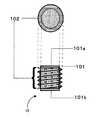
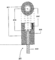
本発明の電極は図1に示す第1構成部材10、および図2に示す第2構成部材20の2つの部材を組み合わせて構成される。
The electrode of the present invention is configured by combining two members, a
第1構成部材10は電極本体101と、この電極本体101の周囲に配置される、雄ねじ加工を施した絶縁体102とからなる。詳細は後述するが、水溶液と界面を形成し電気化学反応が行われる面を電極本体101の上面101a、尖頭加工を施した電気信号取り出し端子203の先端204と接する面を電極本体101の底面101bとする。
The
なお、この上面101aは、性能を評価する触媒を担持することとなる。電極本体101は、ディスク、または線の形状を有する導電性の電極基材である。なお、電極本体101の電極面積が大きい場合にはディスク状の、電極面積が小さい場合には線状の形状を有する基材を用いることが好ましい。電極本体101は白金、金、グラッシーカーボン、銀、ニッケル、パラジウムなどの材料からなり、一般的な電極基材として使用出来るものなら限定しない。また、電極本体101の上面101aに担持する触媒としては白金、金、二酸化マンガンなどを挙げることができる。
The
また、電極本体101の上面101aにおいて電気化学反応が進行すること、電極本体101の底面101bにおいて尖頭加工を施した電気信号取り出し端子先端部204と電気的に接触を行うことから、電極本体101の上面101a、底面101b共に研磨し、不純物を含まないことが望ましい。また、電極本体101の上面101aが著しく傾斜していると図5(a)に示す第1構成部材10を第2構成部材20にねじ込む際に、充分な面積において導通を取れないこと、気密性を保てないこと、および電気化学試験の際に、電極面積を正確に見積もることができないなどの不具合を生じるため、電極本体101の上面101aを水平に作製することが望ましい。
In addition, since the electrochemical reaction proceeds on the
雄ねじ加工を施した絶縁体102は気密性、耐薬品性、耐磨耗性、低磨耗係数、非粘着性、撥水性、絶縁性を有することを要する。例えば、用いる材質としてはPEEK ポリマー( ビクトレックス・エムシー社製 )や、フッ素樹脂テフロン(登録商標 デュポン社製 )等が挙げられる。
The
次に、第2構成部材は図2に示すように、絶縁円筒体201、雌ねじ加工を施した絶縁体202、電気信号取り出し端子203、尖頭加工を施した電気信号取り出し端子先端204、および防水リング205からなる。
Next, as shown in FIG. 2, the second component member includes an insulating
絶縁円筒体201および雌ねじ加工を施した絶縁体202の材質は雄ねじ加工を施した絶縁体102と同様の理由から絶縁体102と同じ材質であることが望ましい。電気信号取り出し端子203、及び尖頭加工を施した電気信号取り出し端子先端204は防錆性、電気伝導性、機械強度に優れた材料、例えばパイプ状あるいは棒状の真鍮などが望ましい。
The material of the insulating
防水リング205に用いる材質としては撥水性、気密性および弾性を有する材料が望ましい。例えば、撥水性シリコーンゴム、シリコン撥水剤を塗布したポリプロピレンゴムなどを用いることができる。
As a material used for the
これらの構成部材を組み合わせて電極を構成する際、電極本体101と尖頭加工を施した電気信号取り出し端子先端204との導通性を向上するために、間に銀などの材料からなる導電性ペースト、あるいはインジウム金属等の柔軟性を有する導電性部材を用いて、接触を行うのも良い。
A conductive paste made of a material such as silver in order to improve the electrical connection between the electrode
次に、本発明の電極の作成方法について図面を参照しながら述べる。 Next, a method for producing the electrode of the present invention will be described with reference to the drawings.
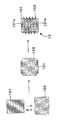
まず、第1構成部材10の作製について説明する。図3に作成フローチャートを示す。中心部に上下方向の穴を貫通させた円筒状絶縁体103に、電極本体101を圧入する。なお、ここで言う円筒状絶縁体103とは、雄ねじ加工前の102のことである。この際、円筒状絶縁体103の基材中、もしくは円筒状絶縁体103と電極本体101との間に気体、液体、もしくは固体の不純物が混入しないように、電極本体101の外径を円筒状絶縁体103の穴の内径より若干大きくする。気体や固体などの不純物が混入するなど、電極本体101が均質な材料により形成されない場合、電気化学試験の結果得られた電流−電位特性に、ノイズ応答が現れるといった影響を及ぼす可能性がある。
First, production of the
次に円筒状絶縁体103の周囲にねじ切り加工を行う。ねじを切るにはダイスもしくは旋盤などを用いる。削り取りの際に電極本体101が外部にさらされることの無いよう、穴の内径の設定に注意する。この工程を経て、円筒状絶縁体103は雄ねじ加工を施した絶縁体102となる。
Next, threading is performed around the
最後に電極本体101の上面101a及び底面101bの研磨を行う。研磨の際には表面に不純物が残留しないように、よくすすぎを行う。
Finally, the
以上で、第1構成部材10の作製を終了する。
This completes the production of the
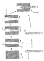
次に第2構成部材20の作製について説明する。図4に作成フローチャートを示す。絶縁円筒体201を準備し(図4(A))、絶縁円筒体201に電気信号取り出し端子203及び先頭加工を施した電気信号取り出し端子先端204を貫通させるための第1穴211を開ける(図4(B))。さらに先ほど開けた第1穴211より直径の大きい(すなわち、断面積が大きい)同心円状の第2穴212を絶縁円筒体201の途中まで絶縁円筒体201の上面201aから開け、その第2穴212の下部に防水リング205を圧入する(図4(C)) 。次に、上記同心円状の第2穴212の内周面に雌ねじ加工を施すことにより(図4(D))、雌ねじ加工を施した絶縁体202を作製する。
Next, production of the
一方、電気信号取り出し端子203を別途用意し(図4(E))、その一端に尖頭加工を施すことにより(図4(F))、先頭加工を施した電気信号取り出し端子先端204を作製する。
On the other hand, an electrical
前記電気信号取り出し端子203を尖頭加工を施した電気信号取り出し端子先端204を先頭に、絶縁円筒体201の底面201bから穴に圧入し、尖頭加工を施した電気信号取り出し端子先端204を防水リング205に貫通させ、絶縁円筒体201内部と電気信号取り出し端子203の境界が浸水しないように封をする(図4(G))。
The electrical
以上の工程を経て、第2構成部材を作製する。 A 2nd structural member is produced through the above process.
次に図5に示すように、先ほど作製した第1構成部材10を第2構成部材20にねじ込み(図5(A))、電極本体101の底面101bを、尖頭加工を施した電気信号取り出し端子先端204に接触させ、電気的に導通を取る(図5(B))。以上の工程を経て、本発明の電気化学測定用電極を作製する。
Next, as shown in FIG. 5, the
次に、上記電極の使用法を説明する。 Next, how to use the electrode will be described.
ここでは、電極に触媒を担持する工程を述べる。電極本体101の上面101aへ物質を担持する方法のひとつに、レーザアブレーション法を用いた気相堆積プロセスがある。ここでは、ターゲットに電極へ担持する触媒物質を選ぶ。例えば、白金、金、マンガン系酸化物などの物質がある。ここでターゲットの材料としては、エキシマレーザー、YAGレーザなどのレーザ照射により昇華する材料であればこれを限定しない。ここで、粉体材料として目的とする電極反応を触媒する物質をターゲット材に選定することが望ましい。なお、レーザアブレーション法の他、真空蒸着法やスパッタ法なども適用可能である。
Here, the step of supporting the catalyst on the electrode will be described. One method for supporting a substance on the
本発明の電気化学測定用電極のうち、第1構成部材10のみ分離し、この第1構成部材10のみを電極設置治具に固定する。前記治具に固定された第1構成部材10を前記レーザアブレーション法による触媒担持装置内に設置する。前記レーザアブレーション手法を用いて、触媒を電極本体101の上面101aに担持した後、第2構成部材20と組み合わせて触媒を担持した電気化学測定用電極を作製し、電気化学測定を行う。
Of the electrodes for electrochemical measurement of the present invention, only the
次に、触媒を担持した電気化学測定用電極の触媒能を評価する方法を説明する。 Next, a method for evaluating the catalytic ability of the electrochemical measurement electrode carrying the catalyst will be described.
前記電気化学測定用電極の反応触媒能を評価する手法として、ボルタンメトリー、クーロメトリーなどが挙げられる。この手法では前記担持工程を経て作製した電気化学測定用電極を作用電極、白金巻き線などを補助電極、銀/塩化銀電極などを参照電極として用いる。酸性、アルカリ性、もしくは中性の溶液を電解質として用い、電解質中に鉄錯体、分子状酸素を溶解させ、電極反応物質とする。溶液中に電極反応物質がある状態で、作用電極と補助電極の間に参照電極電位を基準とした電位を印加する。そこで、作用電極と補助電極の間に流れる電流を検出し、得られる電流―電位特性から、電極に担持された触媒の反応特性を知ることができる。 Examples of a method for evaluating the reaction catalytic ability of the electrochemical measurement electrode include voltammetry and coulometry. In this method, the electrode for electrochemical measurement produced through the supporting process is used as a working electrode, a platinum winding or the like as an auxiliary electrode, and a silver / silver chloride electrode as a reference electrode. An acidic, alkaline, or neutral solution is used as an electrolyte, and an iron complex and molecular oxygen are dissolved in the electrolyte to obtain an electrode reactant. A potential based on the reference electrode potential is applied between the working electrode and the auxiliary electrode in the state where the electrode reactant is present in the solution. Therefore, the current flowing between the working electrode and the auxiliary electrode is detected, and the reaction characteristics of the catalyst supported on the electrode can be known from the obtained current-potential characteristics.
本発明の電極は、気相堆積プロセスにおいて、バインダーを用いることなく触媒を電極本体101の上面101aに担持することが可能である。そのため、触媒粉体をバインダー中に保持された状態で、電極表面に担持される状態とは異なり、本発明の電気化学測定用電極を用いることにより、バインダーの抵抗による過電圧を除去できる。また、ホットプレスを用いる方法とは異なり、触媒層の焼結や触媒層の目的構造例えば多孔性を向上させた構造を保つことが可能となる。また、第1構成部材10と第2構成部材20を組み合わせる手段として、お互いをねじで組み合わせることは、気密性を高く組み合わせることができる効果がある。また、気相堆積プロセスを用いた触媒担持の場面、SEM,ESCAなどの分析の場面に第1構成部材10を適用する際、真空チャンバーの汚れの原因となるテープ剤などを用いずに、冶具への電極の設置を簡便に行えると言った効果がある。また、第2構成部材20は繰り返し使用可能である。
The electrode of the present invention can support a catalyst on the
本発明の電気化学測定用作用電極は、電極触媒を電極面に固定するために用いるバインダーによる、様々な影響を除去し、より高度な電極触媒材料の性能評価に用いることができる。 The working electrode for electrochemical measurements of the present invention can be used for more advanced performance evaluation of electrocatalyst materials by removing various influences due to the binder used for fixing the electrocatalyst to the electrode surface.
10 第1構成部材
101 電極本体
101a 電極本体101の上面
101b 電極本体101の底面
102 雄ねじ加工を施した絶縁体
103 雄ねじ加工を施す前の絶縁体
20 第2成部材
201 絶縁円筒体
202 雌ねじ加工を施した絶縁体
203 電気信号取り出し端子
204 電気信号取り出し端子の先端部分
205 防水リング
211 第1穴
212 第2穴
DESCRIPTION OF
Claims (16)
前記電気化学測定用電極は、第1構成部材および第2構成部材とを有しており、
前記第1構成部材は、電極本体と、前記電極本体の周囲に配置され、雄ねじ加工が施された絶縁体とからなり、
前記第2構成部材は、絶縁円筒体と、電気信号取り出し端子と、前記絶縁円筒体の上面から底面まで貫通している第1穴を有しており、
前記絶縁円筒体の上面には、前記穴よりも断面積が大きい第2穴が形成されており、
前記第2穴には防水リングが圧入されており、
前記第2穴の内周面には雌ねじ加工を施した絶縁体が形成されており、
前記電気信号取りだし端子の先端には尖頭加工が施されており、
前記電気信号取りだし端子は、前記円筒絶縁体の底面側から前記第1穴に挿入されており、
前記尖頭加工が施された電気信号取りだし端子の先端が、前記防水リングを貫通しており、
前記雄ねじ加工が施された絶縁体と前記雌ねじ加工を施した絶縁体とが螺合していることにより、前記第1構成部材が前記第2構成部材にねじ込まれていると共に前記電極本体の底面と前記尖頭加工が施された電気信号取りだし端子の先端とが接触している、電気化学測定用電極。 An electrode for electrochemical measurement,
The electrochemical measurement electrode has a first component and a second component,
The first component member is composed of an electrode main body and an insulator disposed around the electrode main body and subjected to male screw processing,
The second component member has an insulating cylindrical body, an electrical signal extraction terminal, and a first hole penetrating from the top surface to the bottom surface of the insulating cylindrical body,
A second hole having a larger cross-sectional area than the hole is formed on the upper surface of the insulating cylindrical body,
A waterproof ring is press-fitted into the second hole,
On the inner peripheral surface of the second hole, an insulator subjected to female thread processing is formed,
The tip of the electrical signal extraction terminal has been sharpened,
The electrical signal extraction terminal is inserted into the first hole from the bottom side of the cylindrical insulator,
The tip of the electrical signal extraction terminal subjected to the peak processing penetrates the waterproof ring,
The first component member is screwed into the second component member and the bottom surface of the electrode body is formed by screwing the insulator subjected to the male screw processing and the insulator subjected to the female screw processing. An electrode for electrochemical measurement in which the tip of the electrical signal extraction terminal subjected to the tip processing is in contact.
前記電気化学測定用電極は、第1構成部材および第2構成部材とを有しており、
前記第1構成部材は、電極本体と、前記電極本体の周囲に配置され、雄ねじ加工が施された絶縁体とからなり、
前記第2構成部材は、絶縁円筒体と、電気信号取り出し端子と、前記絶縁円筒体の上面から底面まで貫通している第1穴を有しており、
前記絶縁円筒体の上面には、前記穴よりも断面積が大きい第2穴が形成されており、
前記第2穴には防水リングが圧入されており、
前記第2穴の内周面には雌ねじ加工を施した絶縁体が形成されており、
前記電気信号取りだし端子の先端には尖頭加工が施されており、
前記電気信号取りだし端子は、前記円筒絶縁体の底面側から前記第1穴に挿入されており、
前記尖頭加工が施された電気信号取りだし端子の先端が、前記防水リングを貫通しており、
前記電気化学測定用電極の製造方法は、前記雄ねじ加工が施された絶縁体と前記雌ねじ加工を施した絶縁体とを螺合させることにより、前記第1構成部材を前記第2構成部材にねじ込むと共に前記電極本体の底面と前記尖頭加工が施された電気信号取りだし端子の先端とを接触させる電気化学測定用電極形成工程
を有する、電気化学測定用電極の製造方法。 A method for producing an electrode for electrochemical measurement,
The electrochemical measurement electrode has a first component and a second component,
The first component member is composed of an electrode main body and an insulator disposed around the electrode main body and subjected to male screw processing,
The second component member has an insulating cylindrical body, an electrical signal extraction terminal, and a first hole penetrating from the top surface to the bottom surface of the insulating cylindrical body,
A second hole having a larger cross-sectional area than the hole is formed on the upper surface of the insulating cylindrical body,
A waterproof ring is press-fitted into the second hole,
On the inner peripheral surface of the second hole, an insulator subjected to female thread processing is formed,
The tip of the electrical signal extraction terminal has been sharpened,
The electrical signal extraction terminal is inserted into the first hole from the bottom side of the cylindrical insulator,
The tip of the electrical signal extraction terminal subjected to the peak processing penetrates the waterproof ring,
In the method for manufacturing an electrode for electrochemical measurement, the first component member is screwed into the second component member by screwing the insulator subjected to the male screw processing and the insulator subjected to the female screw processing. And a method for producing an electrode for electrochemical measurement, comprising the step of forming an electrode for electrochemical measurement, wherein the bottom surface of the electrode body and the tip of the electrical signal extraction terminal subjected to the sharpening process are brought into contact with each other.
前記第1構成部材は、電極本体と、前記電極本体の周囲に配置され、雄ねじ加工が施された絶縁体とからなり、
前記第2構成部材は、絶縁円筒体と、電気信号取り出し端子と、前記絶縁円筒体の上面から底面まで貫通している第1穴を有しており、
前記絶縁円筒体の上面には、前記穴よりも断面積が大きい第2穴が形成されており、
前記第2穴には防水リングが圧入されており、
前記第2穴の内周面には雌ねじ加工を施した絶縁体が形成されており、
前記電気信号取りだし端子の先端には尖頭加工が施されており、
前記電気信号取りだし端子は、前記円筒絶縁体の底面側から前記第1穴に挿入されており、
前記尖頭加工が施された電気信号取りだし端子の先端が、前記防水リングを貫通しており、
前記物質の電気化学能力を測定する方法は、
前記電極本体の上面に前記物質を担持する物質担持工程、
前記前記雄ねじ加工が施された絶縁体と前記雌ねじ加工を施した絶縁体とを螺合させ、前記第1構成部材を前記第2構成部材にねじ込むと共に前記電極本体の底面と前記尖頭加工が施された電気信号取りだし端子の先端とを接触させて電気化学測定用電極を得る電気化学測定用電極形成工程、および
前記電気信号取りだし端子から前記物質の電気化学能力を測定する電気化学測定系に前記電気化学測定用電極を供する電気化学能力測定工程
を有する、物質の電気化学能力を測定する方法。 A method for measuring the electrochemical ability of a substance using a first component and a second component,
The first component member is composed of an electrode main body and an insulator disposed around the electrode main body and subjected to male screw processing,
The second component member has an insulating cylindrical body, an electrical signal extraction terminal, and a first hole penetrating from the top surface to the bottom surface of the insulating cylindrical body,
A second hole having a larger cross-sectional area than the hole is formed on the upper surface of the insulating cylindrical body,
A waterproof ring is press-fitted into the second hole,
On the inner peripheral surface of the second hole, an insulator subjected to female thread processing is formed,
The tip of the electrical signal extraction terminal has been sharpened,
The electrical signal extraction terminal is inserted into the first hole from the bottom side of the cylindrical insulator,
The tip of the electrical signal extraction terminal subjected to the peak processing penetrates the waterproof ring,
The method for measuring the electrochemical ability of the substance is:
A substance carrying step for carrying the substance on the upper surface of the electrode body;
The insulator subjected to the male thread machining and the insulator subjected to the female thread machining are screwed together, and the first component member is screwed into the second component member, and the bottom surface of the electrode body and the pointed machining are performed. An electrochemical measurement electrode forming step of obtaining an electrode for electrochemical measurement by contacting the tip of the applied electrical signal extraction terminal, and an electrochemical measurement system for measuring the electrochemical ability of the substance from the electrical signal extraction terminal A method for measuring the electrochemical capacity of a substance, comprising an electrochemical capacity measurement step of providing the electrochemical measurement electrode.
The method for measuring the electrochemical ability of a substance according to claim 14, wherein in the substance carrying step, the substance is carried on the upper surface of the electrode body by a laser ablation method.
Priority Applications (1)
| Application Number | Priority Date | Filing Date | Title |
|---|---|---|---|
| JP2004111799A JP2005292097A (en) | 2004-04-06 | 2004-04-06 | Electrode for electrochemical measurement and manufacturing method thereof |
Applications Claiming Priority (1)
| Application Number | Priority Date | Filing Date | Title |
|---|---|---|---|
| JP2004111799A JP2005292097A (en) | 2004-04-06 | 2004-04-06 | Electrode for electrochemical measurement and manufacturing method thereof |
Publications (1)
| Publication Number | Publication Date |
|---|---|
| JP2005292097A true JP2005292097A (en) | 2005-10-20 |
Family
ID=35325170
Family Applications (1)
| Application Number | Title | Priority Date | Filing Date |
|---|---|---|---|
| JP2004111799A Pending JP2005292097A (en) | 2004-04-06 | 2004-04-06 | Electrode for electrochemical measurement and manufacturing method thereof |
Country Status (1)
| Country | Link |
|---|---|
| JP (1) | JP2005292097A (en) |
Cited By (1)
| Publication number | Priority date | Publication date | Assignee | Title |
|---|---|---|---|---|
| KR101768109B1 (en) * | 2016-06-10 | 2017-08-16 | 한국원자력연구원 | Detachable electrode assembly and manufacturing method thereof |
-
2004
- 2004-04-06 JP JP2004111799A patent/JP2005292097A/en active Pending
Cited By (1)
| Publication number | Priority date | Publication date | Assignee | Title |
|---|---|---|---|---|
| KR101768109B1 (en) * | 2016-06-10 | 2017-08-16 | 한국원자력연구원 | Detachable electrode assembly and manufacturing method thereof |
Similar Documents
| Publication | Publication Date | Title |
|---|---|---|
| US7695601B2 (en) | Electrochemical test apparatus and method for its use | |
| Yasuda et al. | Platinum dissolution and deposition in the polymer electrolyte membrane of a PEM fuel cell as studied by potential cycling | |
| EP3519803B1 (en) | Method and apparatus for electrolyte concentration measurement in an electrochemical sensor | |
| JP2001215214A (en) | Hydrogen gas sensor | |
| JPH06229974A (en) | Gas sensor, gas sensor electrode, and gas sensor assembly method | |
| Vogel et al. | Reduction of oxygen on teflon‐bonded platinum electrodes | |
| US10090532B2 (en) | Method for producing fuel cell electrode | |
| JP2000258390A (en) | Gas sensor | |
| CN115389577A (en) | Method and apparatus for measuring humidity using electrochemical gas sensor | |
| EP3561498B1 (en) | Method for a printed electrochemical gas sensor | |
| JP3113499B2 (en) | Electrode for imparting ionic conductivity and electrode-electrolyte assembly and cell using such electrode | |
| EP4074418B1 (en) | Electrode catalyst for fuel cell, electrode catalyst layer for fuel cell, membrane/electrode assembly, and fuel cell | |
| Bidault et al. | Cathode development for alkaline fuel cells based on a porous silver membrane | |
| JP2005292097A (en) | Electrode for electrochemical measurement and manufacturing method thereof | |
| US3415685A (en) | Gas-depolarizable galvanic cell | |
| WO2013032702A1 (en) | Electrochemical sensor comprising polymeric housing | |
| CN113130950B (en) | Method for constructing maltose fuel cell by electrocatalytic oxidation of maltose solution by CuO/nickel foam electrode | |
| KR20220150726A (en) | Nafion-based hydrogen sensor | |
| Easton et al. | Chemically modified gas diffusion electrodes probing electrochemical activity in proton exchange membrane fuel cells | |
| KR100735416B1 (en) | Fuel cell electrode | |
| Allebrod et al. | Foam based gas diffusion electrodes for reversible alkaline electrolysis cells | |
| Osaka et al. | New proposal of evaluation method for DMFC catalyst layers by means of electrochemical impedance spectroscopy | |
| US11340188B2 (en) | Methods and apparatuses for electrochemical analysis of a sample | |
| KR100508890B1 (en) | Monolithic collector-electrode for direct methanol fuel cell using carbon cloth with built-in metal lines and method for manufacturing the same | |
| JP2003287515A (en) | Microelectrode |