EP3561309B1 - Fan, method for its construction and method for dispensing a medium - Google Patents
Fan, method for its construction and method for dispensing a medium Download PDFInfo
- Publication number
- EP3561309B1 EP3561309B1 EP19181992.9A EP19181992A EP3561309B1 EP 3561309 B1 EP3561309 B1 EP 3561309B1 EP 19181992 A EP19181992 A EP 19181992A EP 3561309 B1 EP3561309 B1 EP 3561309B1
- Authority
- EP
- European Patent Office
- Prior art keywords
- fan
- blades
- rotating element
- contour
- fan blades
- Prior art date
- Legal status (The legal status is an assumption and is not a legal conclusion. Google has not performed a legal analysis and makes no representation as to the accuracy of the status listed.)
- Active
Links
- 238000000034 method Methods 0.000 title claims description 18
- 238000010276 construction Methods 0.000 title description 4
- 238000013461 design Methods 0.000 description 12
- 230000001788 irregular Effects 0.000 description 9
- 230000008859 change Effects 0.000 description 4
- 230000006978 adaptation Effects 0.000 description 3
- 238000011161 development Methods 0.000 description 3
- 230000005484 gravity Effects 0.000 description 3
- 238000004519 manufacturing process Methods 0.000 description 3
- 238000001816 cooling Methods 0.000 description 2
- 230000000694 effects Effects 0.000 description 2
- 230000005284 excitation Effects 0.000 description 2
- 230000006870 function Effects 0.000 description 2
- 238000009413 insulation Methods 0.000 description 2
- 230000004048 modification Effects 0.000 description 2
- 238000012986 modification Methods 0.000 description 2
- 230000009467 reduction Effects 0.000 description 2
- 238000001228 spectrum Methods 0.000 description 2
- 238000012935 Averaging Methods 0.000 description 1
- 230000008901 benefit Effects 0.000 description 1
- 238000010586 diagram Methods 0.000 description 1
- 230000004069 differentiation Effects 0.000 description 1
- 230000002349 favourable effect Effects 0.000 description 1
- 239000012530 fluid Substances 0.000 description 1
- 238000009434 installation Methods 0.000 description 1
- 239000000463 material Substances 0.000 description 1
- 238000007620 mathematical function Methods 0.000 description 1
- 230000008447 perception Effects 0.000 description 1
Images


Classifications
-
- F—MECHANICAL ENGINEERING; LIGHTING; HEATING; WEAPONS; BLASTING
- F04—POSITIVE - DISPLACEMENT MACHINES FOR LIQUIDS; PUMPS FOR LIQUIDS OR ELASTIC FLUIDS
- F04D—NON-POSITIVE-DISPLACEMENT PUMPS
- F04D29/00—Details, component parts, or accessories
- F04D29/66—Combating cavitation, whirls, noise, vibration or the like; Balancing
- F04D29/661—Combating cavitation, whirls, noise, vibration or the like; Balancing especially adapted for elastic fluid pumps
- F04D29/666—Combating cavitation, whirls, noise, vibration or the like; Balancing especially adapted for elastic fluid pumps by means of rotor construction or layout, e.g. unequal distribution of blades or vanes
-
- F—MECHANICAL ENGINEERING; LIGHTING; HEATING; WEAPONS; BLASTING
- F04—POSITIVE - DISPLACEMENT MACHINES FOR LIQUIDS; PUMPS FOR LIQUIDS OR ELASTIC FLUIDS
- F04D—NON-POSITIVE-DISPLACEMENT PUMPS
- F04D29/00—Details, component parts, or accessories
- F04D29/26—Rotors specially for elastic fluids
- F04D29/28—Rotors specially for elastic fluids for centrifugal or helico-centrifugal pumps for radial-flow or helico-centrifugal pumps
- F04D29/281—Rotors specially for elastic fluids for centrifugal or helico-centrifugal pumps for radial-flow or helico-centrifugal pumps for fans or blowers
- F04D29/282—Rotors specially for elastic fluids for centrifugal or helico-centrifugal pumps for radial-flow or helico-centrifugal pumps for fans or blowers the leading edge of each vane being substantially parallel to the rotation axis
-
- F—MECHANICAL ENGINEERING; LIGHTING; HEATING; WEAPONS; BLASTING
- F05—INDEXING SCHEMES RELATING TO ENGINES OR PUMPS IN VARIOUS SUBCLASSES OF CLASSES F01-F04
- F05D—INDEXING SCHEME FOR ASPECTS RELATING TO NON-POSITIVE-DISPLACEMENT MACHINES OR ENGINES, GAS-TURBINES OR JET-PROPULSION PLANTS
- F05D2240/00—Components
- F05D2240/20—Rotors
- F05D2240/30—Characteristics of rotor blades, i.e. of any element transforming dynamic fluid energy to or from rotational energy and being attached to a rotor
- F05D2240/303—Characteristics of rotor blades, i.e. of any element transforming dynamic fluid energy to or from rotational energy and being attached to a rotor related to the leading edge of a rotor blade
-
- F—MECHANICAL ENGINEERING; LIGHTING; HEATING; WEAPONS; BLASTING
- F05—INDEXING SCHEMES RELATING TO ENGINES OR PUMPS IN VARIOUS SUBCLASSES OF CLASSES F01-F04
- F05D—INDEXING SCHEME FOR ASPECTS RELATING TO NON-POSITIVE-DISPLACEMENT MACHINES OR ENGINES, GAS-TURBINES OR JET-PROPULSION PLANTS
- F05D2240/00—Components
- F05D2240/20—Rotors
- F05D2240/30—Characteristics of rotor blades, i.e. of any element transforming dynamic fluid energy to or from rotational energy and being attached to a rotor
- F05D2240/304—Characteristics of rotor blades, i.e. of any element transforming dynamic fluid energy to or from rotational energy and being attached to a rotor related to the trailing edge of a rotor blade
Definitions
- Fan method for its construction and method for dispensing medium
- the present invention relates to the field of sucking in gaseous medium and its pressurized discharge and in particular to the field of fans such as centrifugal fans, axial fans and diagonal fans.
- U.S. 2,238,749 discloses a fan having a plurality of fan blades, in each of which different deformations or deformations are alternately provided with no deformations at the trailing edge in order to reduce noise.
- a fan with a fan wheel which comprises suction blades extending in the radial and axial direction with a leading edge facing an axial inlet direction of the fan wheel, at least one suction blade having a swirl device for generating microturbulence in the area of its leading edge.
- a fan wheel in a design as a radial or diagonal fan consisting of a cover disk with an inlet opening, a bottom disk and several fan blades distributed over the circumference of the inlet opening and around an axis of rotation as well as with blade channels formed in the circumferential direction between the adjacent fan blades, which lead radially or diagonally outward from the area of the inlet opening and form blow-out openings in the outer area, the blade channels being designed to be so large in terms of their effective flow cross-section that a turbulent flow with a Reynolds number significantly greater than 2300 is achieved during operation, and the cover disk and / or the bottom disk have / has a non-rotationally symmetrical geometry, the respective non-rotationally symmetrical geometry having a continuous, point-continuous course viewed in the axial or axially parallel direction.
- US 2012/321495 A1 discloses a centrifugal fan in an electronic device cooling system with asymmetrical blade spacing with acceptable balance.
- the asymmetrical blade spacing is determined according to a set of desired acoustic artifacts that are favorable and a balance similar to that for the same fan blade spacing.
- the fan impeller may include sixty-one fan blades.
- a starting point of the present invention is explained below with reference to an exemplary application of a radial fan for cooling converters by means of an air flow.
- f D. n ⁇ z 60 describe, where f D is the fundamental frequency of the rotating sound, n is the speed and z is the number of blades.
- a fan as defined in claim 1 is proposed according to first aspects.
- a method for constructing a fan as defined in claim 8 is proposed according to second aspects.
- the specifically provided asymmetry thus allows an improved noise behavior, which is due to the fact that the respective individual impulses of the individually designed blades differ from one another, so that the rotational sound occurring in known solutions is to a certain extent "smeared" in its frequency spectrum.
- the asymmetry includes that when the rotating element is imagined to be rotated by one or two fractions of a full revolution corresponding to the number of blades, the rotating element is rotated with regard to at least one property of an blade that influences the operation of the respective blade a component of the fan has media impulse exerted, differs from the rotating element that is not rotated.
- the design of the airfoil cannot be mapped onto itself by rotating one or two angular sections between two adjacent airfoils.
- an image on itself results for every (imaginary) rotation of 60 °.
- only one full (imaginary) revolution preferably results in the rotating element being mapped onto itself.
- the property that has an influence on a media pulse exerted by the respective blade during operation on a component of the fan includes a contour and / or inclination of a trailing edge of the blade, and an offset of an arrangement of the blade with respect to a rotational symmetry of the rotating element given output arrangement, the rotational symmetry corresponding to a number of blades of the rotating element.
- the property which has an influence on a media pulse exerted by the respective blade during operation on a component of the fan includes, a contour and / or inclination of a leading edge of the airfoil, and / or a surface contour of the airfoil.
- the surface contours of an airfoil are already modified in known solutions with respect to a comparatively simply curved surface.
- all of the airfoils are modified in the same way, for example by providing depressions, raised areas, deviations in curvature and the like.
- this deviation can also consist in the fact that one of the blades has a well-known surface contour without modification, while the other blade or blades have modified surface contours have, as consist in the fact that the affected blades each have their own, differing modifications.
- the outflow edges are arranged parallel to the axis of rotation.
- An inclined position of the discharge cross section results in a delay in the angle of impact the current.
- the inclination - with a modified contour of the edge, possibly averaged over the extension of the edge - is preferably in a range from 5 ° to 15 °, particularly preferably in a range from 8 ° to 12 °.
- the airfoil can also be differentiated in the leading edge.
- the property that has an influence on a media pulse exerted by the respective blade during operation on a component of the fan comprises the contour of the trailing edge of the blade, with the at least two blades differing in terms of a deviation in the contour of their respective Differentiate the trailing edge from a given exit trailing contour.
- exit outflow contour i.e. as a reference for quantifying a deviation or differentiation between blades
- a linear edge with a straight course parallel to the axis of rotation can be assumed in a radial fan, possibly also an inclined linear edge.
- the exit outflow contour only serves as a benchmark, without such an exit outflow contour having to have been present, for example, during the manufacture of the airfoil.
- the initial contour is, however, not limited to a linear shape, in particular in view of the blade-blade contours that predominate in the respective fan designs.
- the property that has an influence on a media pulse exerted by the respective blade during operation on a component of the fan comprises the contour of the leading edge of the blade, with the at least two blades differing in terms of a deviation in their contour differentiate the respective leading edge from a given exit entry contour.
- the deviation of the contour of the trailing edge and / or the leading edge of at least one airfoil from the exit trailing contour or the exit inflow contour varies over the extension the trailing edge or the leading edge, a maximum deviation in one direction being at least 1/150 of the airfoil length and a maximum deviation in a direction opposite to the direction being at least 1/150 of the airfoil length.
- the deviation of the contour of the edge (s) can in turn be regular (for example in the form of a wavy line or zigzag shape), although an irregularity is preferred.
- the size of the deviation is provided in such a way that there is a relevant effect on the media pulse, so that a microscopic roughness (e.g.
- the edge is not yet to be understood as a deviation.
- the maximum deviation in the direction is less than 1/15 of the airfoil length and the maximum deviation in the opposite direction is less than 1/15 of the airfoil length.
- the contour preferably deviates from the initial contour, which is used as a reference, in such a way that the maximum deviation lies in the range determined by the above values. Particularly in the case of an irregular configuration of the edge (s), it can be provided that the deviation from an inclined starting contour tends to zero on average.
- the offset of the arrangement comprises an orientation and / or a positioning of the blade.
- An arrangement of the blades that breaks the symmetry can also influence the media impulses in the desired manner, which are caused by the blades when they pass through another component of the fan.
- an arrangement of a blade can be changed compared to a (conceptually assumed) conventional arrangement, for example in the case of a radial fan, on the one hand by rotating the blade about an axis that is parallel to the axis of rotation, i.e. deviates in its orientation.
- Another change can be described by the fact that the airfoil in the Impeller of the radial fan defined level is arranged offset.
- the offset in the plane and a change in the orientation are preferably combined with one another.
- each airfoil of the plurality of airfoils differs from every other airfoil of the plurality of airfoils in a contour and / or inclination of the trailing edge of the airfoils.
- the fan is a radial fan or a diagonal fan and the rotating element comprises a support disk and / or a cover disk, an outer contour of the support disk and / or the cover disk having a deviation that varies over the circumference compared to a circle , with a maximum outward deviation of at least 1/150 of the disk diameter and a maximum inward deviation of at least 1/150 of the disk diameter.
- the support disk and the cover disk of a radial fan impeller also contribute to the rotary sound, so that the invention here can include influencing the rotary sound by appropriately designing the contour.
- the cover disk and / or the support disk compensation for an imbalance of the blade arrangement that occurs due to deviations of the blade blades from one another can be achieved.
- the differences with regard to the trailing edge and the arrangement are dimensioned such that a center of mass of the rotating element coincides with an axis of rotation of the rotating element.
- the variations of the dimensioning used for this, that the center of gravity of the rotating element coincides with the axis of rotation (i.e. that no imbalance occurs), are not due to the previously mentioned deviations, for example of the blades limited against each other.
- Fig. 1 shows a schematic representation of a radial fan to illustrate noise development during operation.
- Figures 1a and 1b show the velocity profile in the casing and after the blade outlet.
- Fig. 2 shows a schematic side view of an impeller as an aspect of a first embodiment of a fan according to the invention.
- the fan is a radial fan, the impeller 10 having a support disk 12 and a cover disk 14, between which blades 16a, 16b, 16c, 16d, 16e are attached.
- the person skilled in the art is familiar with the basic complexity of an impeller and also the other elements of a fan (here radial fan), so that no further explanation is necessary in this regard.
- the blades each have a trailing edge 16a ', 16b', 16c ', 16d'.
- FIG. 3 illustrates views of blades of the impeller shown in Fig. 2 is illustrated.
- the airfoils 16a-16g point to the one shown in FIG Fig. 3 left side the respective trailing edge 16a'-16g '.
- the edges facing the support disk and the cover disk are of conventional design.
- the leading edges 16a "-16g" (each in the illustration of FIG Fig. 3 right) conventionally executed.
- trailing edges 16a'-16g 'of the airfoils 16a-16g each have a contour which differs for each trailing edge from all trailing edges of the other airfoils. In other words, all trailing edges 16a'-16g 'are different from one another in pairs.
- the contours are different in an order of magnitude above (preferably significantly above) inherently unavoidable fluctuations in a component geometry (on a sufficiently small scale, differences can always be identified for otherwise supposedly identical components, in particular due to the manufacturing process) that, for example, when the contour lines of two trailing edges are superimposed, these lines cannot, or at least not completely, be brought into congruence.
- the contour can preferably be designed so that the edge from the support disk to the cover disk represents random or at least pseudo-random projections or recesses in relation to an imaginary "center line" within the scope of the continuity of the edge.
- an edge profile can be described by a rule or a mathematical function, in which case, however, all blade edges still differ from one another, either by applying different rules or functions and / or by applying different parameters for one same rule or function.
- FIG. 4 Illustrated further views of the impeller shown in Fig. 2 is illustrated.
- Figure 4a shows a top view of the impeller 10 with the cover disk removed, so that the position and orientation of the blades 16a-16g on the support disk 12 can be seen.
- the airfoils also have a mass distribution that differs from one another. In order to nevertheless achieve that the center of mass coincides with the axis of rotation of the impeller 10 in a manner sufficient for a person skilled in the art (i.e.
- the blades 16a-16g are each essentially perpendicular a plane defined by the support disk and a respective outer end at corresponding interval positions each pivoted about an axis parallel to the axis of rotation of the impeller 10, so that the center of gravity of the impeller 10 (then with cover plate 14) is at a desired position.
- the design of the contour of the trailing edge 16a "-16g" and the arrangement of the respective airfoil are related to one another.
- the blades 16a-16g and the support plate 12 or the cover plate 14 if the blades are to be attached to the cover plate 14 first) are coded with one another. This can be achieved, for example, in that the blade blades have clearly arranged and / or combined extensions and the support disk is provided with suitable slots for receiving the extensions at the corresponding positions (see also Fig. 7 ).
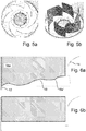
- FIG. 5 shows to Fig. 4 comparable views of a conventional impeller.
- the conventional impeller has a symmetry with respect to a rotation of 60 °.
- Figure 5b The same applies to Figure 5b .
- Fig. 6 shows a trailing edge of an airfoil of a fan according to an embodiment of the invention in detail and in comparison with a conventional airfoil.
- the blade 16 shown which is arranged between the support disk 12 and the cover disk 14 of the rotating element of the fan, has a trailing edge 16a 'which initially extends from a corresponding trailing edge of an airfoil of a conventional fan ( Figure 6b ) differs by its irregularity.
- a center line 18, which represents a straight averaging of the contour of the trailing edge 16a 'from its contact with the support disk 12 to its contact with the cover disk 14, compared to a vertical connection between support disk 12 and cover disk 14 (parallel to the axis of rotation of the impeller) is inclined. Even if it can be provided that this center line and the contour coincide with one another at the respective ends, this feature is not necessary for the invention.
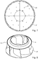
- Fig. 7 shows a plan view of a support disk of an impeller of an embodiment of a fan according to the invention.
- the support disk 12 'of this embodiment has an irregular circumference, which is shown in FIG Fig. 7 is illustrated in comparison to an approximately circular perimeter 20. On the basis of this regular circumference 22, the irregularity of the support disk 12 'can be easily recognized.
- Such a design of the outer contour of the support plate 12 ' leads to the fact that a media impulse caused by the support disk 12 'during the rotation of the impeller with this support disk loses continuity and / or regularity, so that less disturbing noises are produced.
- mounting slots 20 provided in the support disk 12 ' can be seen, which are used to accommodate corresponding extensions of the blades during the assembly of the impeller, whereby these mounting slots 20, with a corresponding arrangement, extension and / or shape, can serve to ensure that the blades are only in one can be mounted in a predetermined manner and arrangement. In this way it can be avoided, for example, that an imbalance is introduced into the impeller by mistakenly interchanging two irregular blades.
- Fig. 8 shows an impeller of an embodiment of a fan according to the invention with the support disk from FIG Fig. 7 .
- the support disk 12 'as part of an impeller 10' together with blades is comparable to Fig. 2 and Fig. 3 and a cover plate 14 is shown.
- Fig. 9 illustrates a blade according to a further embodiment of a fan according to the invention.
- the airfoil 16h is similar to the airfoil 16a-16g discussed above, with an irregularly shaped contour of a trailing edge 16h 'and projections 24 (matching the corresponding assembly slots of a support disk, see e.g. Fig. 7 ) Mistake.
- the leading edge 26 of the airfoil 16h is also equipped with an irregular contour, which also helps to reduce the development of disruptive noise.
- Fig. 10 illustrated the shovel blade Fig. 9 in an installed state in an impeller.
- the blade 16h which is shown in FIG Fig. 9 is illustrated, shown in the assembled state between the support plate 12 and the cover plate 14 of the impeller 10 ′′.
- Fig. 11 shows views of a cover plate of an embodiment of a fan according to the invention.
- Figure 11a shows the cover plate 14 'in a plan view
- Figure 11b shows the cover plate 14 'in a perspective view.
- a regular circumference 22 ' is also shown here as a reference.
- FIG. 11 shows a view of an impeller with the cover disk from FIG Fig. 11 .
- the impeller 10 '" has, like that in Fig. 8
- the illustrated impeller 10 ′′ has the support disk 12 ′ with an irregular circumference, the impeller 10 ′ ′′ also having blade blades with irregular trailing edge contours and at least one blade 16g with an irregular trailing edge and an irregular leading edge (see Fig. 9 ) is provided.
- the impeller 10 '" also has the cover plate 14', which in FIG Figures 11a and 11b is shown.
- Fig. 13 shows another illustration of the impeller shown in Fig. 2 is illustrated.
- the impeller 10 comprises the support disk 12, several blades 16a-16g (the blade 16d is shown in FIG Fig. 13 covered by the cover plate 14) and the cover plate 14.
- the illustrated contours of the trailing edges, the leading edge, the support disk and the cover disk are only intended to serve as an illustration, without the invention being restricted to the specific shapes.
- Fig. 14 shows schematically a flowchart which illustrates an embodiment of a method according to the invention for constructing a fan.
- two blades are first designed, in which step the trailing edges and, if applicable, the leading edges and / or the surface contours are each designed in such a way that they differ from one another.
- step 103 a further airfoil is first designed, this airfoil in turn being designed in such a way that it differs from all previously designed airfoils with regard to at least the trailing edge contour and / or inclination. This step is repeated until the intended number of blades has been laid out.
- step 105 the positions and orientations of the airfoils are initially determined provisionally, with these positions and / or orientations being iteratively adapted in step 107 until a desired reduction in an imbalance possibly caused by the different configurations of the airfoil is achieved and thus the construction of the fan can be regarded as completed in this regard.
- the method described above represents only one embodiment of the method according to the invention.
- An adaptation of the orientation and / or positioning of the blade blades may possibly be unnecessary or supplemented by adapting the outer contours of the support disk and / or the cover disk, this adaptation advantageously being an irregular adaptation, as is shown, for example, in FIGS Fig.
- Fig. 15 shows schematically a flow diagram which illustrates an embodiment of a method according to the invention for the pressurized delivery of gaseous medium.
- step 111 the fan is put into operation and begins to suck in medium and to release it under the application of pressure.
- the rotating element of the fan rotates so that the various blades of the rotating element pass one component of the fan one after the other.
- steps 113, 115 and 117 these sequence of steps being repeated until the fan is switched off (step 119).
- the media impulses that are connected to the component with passages 113, 115 and 117 are different, so that these media impulses do not interrelate can combine together to form an annoying noise.
Description
Ventilator, Verfahren zu dessen Konstruktion und Verfahren zur Abgabe von Medium Die vorliegende Erfindung betrifft das Gebiet des Ansaugens von gasförmigem Medium und dessen druckbeaufschlagter Abgabe und insbesondere das Gebiet von Ventilatoren wie Radialventilatoren, Axialventilatoren und Diagonalventilatoren.
Ein Ausgangspunkt der vorliegenden Erfindung wird im Folgenden anhand einer beispielhaften Anwendung eines Radialventilators für die Kühlung von Umrichtern durch einen Luftstrom erläutert.A starting point of the present invention is explained below with reference to an exemplary application of a radial fan for cooling converters by means of an air flow.
Es wurde gefunden, dass beim Einsatz von Radialventilatoren bei vielen Umrichtervarianten im Betrieb ein unangenehmes Geräusch auftritt, das auf einen sogenannten Drehklang zurückzuführen ist.It has been found that when radial fans are used with many converter variants, an unpleasant noise occurs during operation, which is due to a so-called rotating sound.
Durch das Passieren jeder einzelnen Radialschaufel an umgebenden Bauteilen wie Gehäusewänden entsteht jeweils ein Einzelimpuls, der durch seine harmonische Wiederkehr einen Drehton oder Drehklang erzeugt. Dieser ist im Frequenzspektrum deutlich zu erkennen und lässt sich mit der Formel ![]()
![]()
Bei einem Ventilatorlaufrad mit sieben Schaufeln und einer Drehzahl von 1450 min-1 ist eine Grundfrequenz des Drehklangs von ca. 170 Hz zu erwarten ![]()
![]()
Die obige Problematik ist beispielhaft für den Fall eines Radialventilators angesprochen, wobei entsprechendes etwa auch bei Axialventilatoren und Diagonalventilatoren gilt.The above problem is addressed by way of example for the case of a radial fan, the same also applying, for example, to axial fans and diagonal fans.
Um eine störende Wahrnehmung bei Betriebs eines Ventilators zu vermeiden und auch um generell Schallimmissionsaspekten Genüge zu tun, werden bisher Dämmungsmaßnahmen ergriffen, die einen zusätzlichen Aufwand und damit zusätzliche Kosten mit sich bringen.In order to avoid disruptive perception when a fan is in operation and also to generally satisfy sound immission aspects, insulation measures have been taken up to now, which entail additional effort and thus additional costs.
Ein der vorliegenden Erfindung zugrundeliegendes Ziel ist es, einen Ventilator, ein Verfahren zu dessen Konstruktion und ein Verfahren zur druckbeaufschlagten Abgabe von gasförmigem Medium bereitzustellen, bei dem die bei bekannten Lösungen auftretenden Probleme vermieden oder zumindest verringert werden.It is an object of the present invention to provide a fan, a method for its construction and a method for the pressurized delivery of gaseous medium, in which the problems occurring with known solutions are avoided or at least reduced.
Es ist daher gewünscht, eine Lösung vorzustellen, bei der beispielsweise störende Geräusche/Frequenzbereiche in verringertem Maße auftreten, ohne dass hierzu gesonderte Dämmungsmaßnahmen oder dergleichen vorgesehen werden müssen.It is therefore desirable to present a solution in which, for example, disruptive noises / frequency ranges occur to a reduced extent, without having to provide separate insulation measures or the like for this purpose.
Erfindungsgemäß wird nach ersten Aspekten ein Ventilator vorgeschlagen, wie er in Anspruch 1 definiert ist.According to the invention, a fan as defined in claim 1 is proposed according to first aspects.
Erfindungsgemäß wird nach zweiten Aspekten ein Verfahren zur Konstruktion eines Ventilators vorgeschlagen, wie es in Anspruch 8 definiert ist.According to the invention, a method for constructing a fan as defined in claim 8 is proposed according to second aspects.
Erfindungsgemäß wird nach weiteren Aspekten ein Verfahren zur druckbeaufschlagten Abgabe von gasförmigem Medium vorgeschlagen, wie es in Anspruch 9 definiert ist.According to the invention, according to further aspects, a method for the pressurized delivery of gaseous medium is proposed, as is defined in claim 9.
Ein Teil des Hintergrunds der vorliegenden Erfindung findet sich in den folgenden Überlegungen.Part of the background to the present invention resides in the following considerations.
Es wurde gefunden, dass durch eine konstruktive Änderung beispielsweise der Schaufelwinkel und der Schaufelaußenkontur (Abströmkante) eine Asymmetrie zu erzeugen ist, die die harmonische Ausbreitung der Geschwindigkeit nach dem Verlassen des Radiallaufrades eliminiert bzw. stört. Hierbei kann ungeachtet der fluiddynamischen Asymmetrie der Laufradgeometrie eine mechanische Symmetrie zum Massenschwerpunkt erhalten bleiben, was im Einzelnen bedeutet, dass ein Auswuchten ähnlichen bzw. sogar gleichen Voraussetzungen unterliegt wie bei einem bekannten Ventilatorlaufrad. Es darf zudem angenommen werden, dass auch im Hinblick auf etwa Festigkeit und Schwingungsausprägung bei einer entsprechenden Laufradgeometrie keine relevanten negativen Änderungen erkennbar sind. Die Verringerung der durch die aeromechanische Anregung erzeugte Schwingungsanregung der in der Umgebung befindlichen Bauteile bringt zudem einen Vorteil dahingehend mit sich, dass diese Bauteile damit geringeren Belastungen ausgesetzt sind.It has been found that a design change, for example the blade angle and the outer contour of the blade (trailing edge), can be used to create an asymmetry that eliminates or disrupts the harmonic propagation of the speed after leaving the radial impeller. Regardless of the fluid dynamic asymmetry of the impeller geometry, a mechanical symmetry to the center of gravity can be maintained, which means in detail that balancing is subject to similar or even the same conditions as with a known fan impeller. It can also be assumed that with a corresponding impeller geometry, no relevant negative changes can be identified with regard to strength and vibration characteristics. The reduction in the vibration excitation of the components located in the vicinity generated by the aeromechanical excitation also has the advantage that these components are therefore exposed to lower loads.
Die gezielt vorgesehene Asymmetrie erlaubt damit ein verbessertes Geräuschverhalten, dass darauf zurückzuführen ist, dass sich auch die jeweiligen Einzelimpulse der individuell ausgeführten Schaufelblätter voneinander unterscheiden, so dass der bei bekannten Lösungen auftretende Drehklang in seinem Frequenzspektrum gewissermaßen "verschmiert" wird.The specifically provided asymmetry thus allows an improved noise behavior, which is due to the fact that the respective individual impulses of the individually designed blades differ from one another, so that the rotational sound occurring in known solutions is to a certain extent "smeared" in its frequency spectrum.
Die oben angesprochene Asymmetrie ist schon gegeben, wenn sich zwei Schaufelräder in einer der Eigenschaften unterscheiden, die Einfluss auf den von dem jeweiligen Schaufelblatt im Betrieb auf ein Bauteil des Ventilators ausgeübten Medienimpuls haben. Dies kann bedeuten, dass hinsichtlich dieser Eigenschaft alle Schaufelblätter bis auf eines identisch sind, dass sich also dieses eine der Schaufelblätter von allen anderen Schaufelblätter in dieser Eigenschaft unterscheidet. Der Unterschied zwischen zwei Schaufelrädern kann auch damit verbunden sein, dass unabhängig von diesem Unterschied eines oder mehrere Paare von Schaufelblättern (die nicht notwendigerweise benachbart zueinander angeordnet sein müssen, um in diesem Sinne als Paar angesehen zu werden) vorliegen, bei denen jeweils wenigstens ein Unterschied in einer der Eigenschaften vorhanden ist. Allerdings ist gemäß der Erfindung vorgesehen, dass sich jedes Schaufelblatt sowohl in der Kontur und/oder Neigung seiner Abströmkante als auch in seinem Versatz gegenüber einer Rotationssymmetrie von jedem anderen Schaufelblatt unterscheidet.The asymmetry mentioned above is already given when two impellers differ in one of the properties that influence the media impulse exerted by the respective impeller on a component of the fan during operation. This can mean that with regard to this property, all but one of the airfoils are identical, that is to say that this one of the airfoils differs from all of the other airfoils in this property. The difference between two paddle wheels can also be connected with the fact that, regardless of this difference, there are one or more pairs of paddle blades (which do not necessarily have to be arranged adjacent to one another in order to be viewed as a pair in this sense), each of which has at least one difference is present in one of the properties. However, it is provided according to the invention that each airfoil differs from every other airfoil both in the contour and / or inclination of its trailing edge and in its offset with respect to a rotational symmetry.
Vorzugsweise beinhaltet die Asymmetrie, dass sich bei einer gedanklichen Drehung des rotierenden Elements um einen oder zwei der Anzahl der Schaufelblätter entsprechenden Bruchteile einer vollen Umdrehung das gedanklich gedrehte rotierende Element hinsichtlich wenigstens einer Eigenschaft eines Schaufelblatts, die Einfluss auf den von dem jeweiligen Schaufelblatt im Betrieb auf ein Bauteil des Ventilators ausgeübten Medienimpuls hat, von dem gedanklich nicht gedrehten rotierenden Element unterscheidet. Mit anderen Worten lässt sich das Schaufelblatt in seiner Ausgestaltung nicht durch eine Drehung von einem oder zwei Winkelabschnitten zwischen zwei benachbarten Schaufelblättern auf sich selbst abbilden. In einem Fall eines herkömmlichen, symmetrischen Laufrads mit sechs identischen Schaufelblättern, die in gleichen Intervallen angeordnet sind, ergibt sich eine Abbildung auf sich selbst bei jeder (gedanklichen) Drehung um 60°. Vorzugsweise führt bei einem erfindungsgemäßen Ventilator lediglich eine volle (gedankliche) Umdrehung dazu, dass das rotierende Element auf sich selbst abgebildet wird.Preferably, the asymmetry includes that when the rotating element is imagined to be rotated by one or two fractions of a full revolution corresponding to the number of blades, the rotating element is rotated with regard to at least one property of an blade that influences the operation of the respective blade a component of the fan has media impulse exerted, differs from the rotating element that is not rotated. In other words, the design of the airfoil cannot be mapped onto itself by rotating one or two angular sections between two adjacent airfoils. In a case of a conventional, symmetrical impeller with six identical blades, which are arranged at equal intervals, an image on itself results for every (imaginary) rotation of 60 °. In the case of a fan according to the invention, only one full (imaginary) revolution preferably results in the rotating element being mapped onto itself.
Es hier darauf hingewiesen, dass die hier dargestellten Überlegungen und Merkmale für jede Art von Ventilatoren gelten, auch wenn die vorliegende Erfindung vornehmlich anhand des Beispieltypus eines Radialventilators beschrieben und illustriert ist. Dem Fachmann sollte klar sein, dass die Ausführungen jeweils direkt oder in analoger Weise auch für andere Arten von Ventilatoren gelten, so dass die Erfindung nicht auf Radialventilatoren beschränkt zu verstehen ist.It should be noted here that the considerations and features presented here apply to every type of fan, even if the present invention is primarily described and illustrated using the example type of a radial fan. It should be clear to the person skilled in the art that the explanations in each case apply directly or in an analogous manner to other types of fans, so that the invention is not to be understood as being limited to radial fans.
Erfindungsgemäß umfasst die Eigenschaft, die Einfluss auf einen von dem jeweiligen Schaufelblatt im Betrieb auf ein Bauteil des Ventilators ausgeübten Medienimpuls hat, eine Kontur und/ oder Neigung einer Abströmkante des Schaufelblatts, und einen Versatz einer Anordnung des Schaufelblatts gegenüber einer durch eine Rotationssymmetrie des rotierenden Elements gegebenen Ausgangsanordnung, wobei die Rotationssymmetrie einer Anzahl an Schaufelblättern des rotierenden Elements entspricht.According to the invention, the property that has an influence on a media pulse exerted by the respective blade during operation on a component of the fan includes a contour and / or inclination of a trailing edge of the blade, and an offset of an arrangement of the blade with respect to a rotational symmetry of the rotating element given output arrangement, the rotational symmetry corresponding to a number of blades of the rotating element.
In einer vorteilhaften Ausgestaltung eines Aspekts der Erfindung umfasst die Eigenschaft, die Einfluss auf einen von dem jeweiligen Schaufelblatt im Betrieb auf ein Bauteil des Ventilators ausgeübten Medienimpuls hat, eine Kontur und/oder Neigung einer Eintrittskante des Schaufelblatts, und/oder eine Oberflächenkontur des Schaufelblatts.In an advantageous embodiment of an aspect of the invention, the property which has an influence on a media pulse exerted by the respective blade during operation on a component of the fan includes, a contour and / or inclination of a leading edge of the airfoil, and / or a surface contour of the airfoil.
Die Oberflächenkonturen eines Schaufelblatts werden bereits bei bekannten Lösungen gegenüber einer vergleichsweise einfach gekrümmten Oberfläche modifiziert. Anders als bei der vorliegenden Erfindung ist hierbei allerdings vorgesehen, dass alle Schaufelblätter in der gleichen Weise modifiziert werden, etwa durch Vorsehen von Vertiefungen, erhabenen Bereichen, Abweichungen in der Krümmung und dergleichen. Soweit die Oberflächenkontur Teil der Eigenschaft bzw. Eigenschaftsgruppe ist, die im Rahmen der Erfindung bei wenigstens zwei Schaufelblättern voneinander abweichen, kann diese Abweichung ebenso darin bestehen, dass eines der Schaufelblätter eine altbekannte Oberflächenkontur ohne Modifikation aufweist, während das bzw. die anderen Schaufelblätter modifizierte Oberflächenkonturen aufweisen, wie darin bestehen, dass die betroffenen Schaufelblätter jeweils eigene, voneinander abweichende Modifikationen aufweisen.
Bei bekannten Anordnungen von Schaufelblättern eines Ventilators besteht jeweils eine Rotationssymmetrie entsprechend der Anzahl von Schaufelblättern, so dass etwa ein Querschnitt eines Ventilators mit sechs Schaufelblättern bei einer Drehung um 60° um die Rotationsachse wieder mit sich zusammenfällt. Die Anordnung umfasst hierbei insbesondere die eigentliche Position des Schaufelblatts also auch die Orientierung des Schaufelblatts.
Es wird angenommen, dass - neben der Ausrichtung und Positionierung des Schaufelblatts - die Kontur der Abströmkante des Schaufelblatts besonders starken Einfluss auf den Medienimpuls hat, der durch das Passieren dieser Kante an einem Bauteil des Ventilators verursacht wird. Es wurde gefunden, dass neben der Kontur auch die Neigung dieser Kante als zu variierende Eigenschaft nutzbar ist. Bei bekannten Radialventilatoren sind beispielsweise die Abströmkanten parallel zur Rotationsachse angeordnet. Bei einer Schrägstellung des Ausblasquerschnitts ergibt sich jeweils eine Verzögerung des Aufprallwinkels der Strömung. Vorzugsweise liegt die Neigung - bei modifizierter Kontur der Kante ggf. über die Ausdehnung der Kante gemittelt - in einem Bereich von 5° bis 15°, besonders bevorzugt in einem Bereich von 8° bis 12°.The surface contours of an airfoil are already modified in known solutions with respect to a comparatively simply curved surface. In contrast to the present invention, however, it is provided here that all of the airfoils are modified in the same way, for example by providing depressions, raised areas, deviations in curvature and the like. Insofar as the surface contour is part of the property or property group that deviate from one another in at least two blades within the scope of the invention, this deviation can also consist in the fact that one of the blades has a well-known surface contour without modification, while the other blade or blades have modified surface contours have, as consist in the fact that the affected blades each have their own, differing modifications.
In known arrangements of fan blades, there is a rotational symmetry corresponding to the number of blades, so that, for example, a cross section of a fan with six blades coincides again with a rotation of 60 ° about the axis of rotation. The arrangement here includes in particular the actual position of the airfoil, that is to say also the orientation of the airfoil.
It is assumed that - in addition to the alignment and positioning of the airfoil - the contour of the trailing edge of the airfoil has a particularly strong influence on the media impulse caused by passing this edge on a component of the fan. It was found that, in addition to the contour, the inclination of this edge can also be used as a property to be varied. In known radial fans, for example, the outflow edges are arranged parallel to the axis of rotation. An inclined position of the discharge cross section results in a delay in the angle of impact the current. The inclination - with a modified contour of the edge, possibly averaged over the extension of the edge - is preferably in a range from 5 ° to 15 °, particularly preferably in a range from 8 ° to 12 °.
Ähnlich wie bei der Abströmkante kann auch die Unterscheidung der Schaufelblätter in der Eintrittskante bestehen.Similar to the trailing edge, the airfoil can also be differentiated in the leading edge.
In einer bevorzugten Variante der obigen Ausgestaltung umfasst die Eigenschaft, die Einfluss auf einen von dem jeweiligen Schaufelblatt im Betrieb auf ein Bauteil des Ventilators ausgeübten Medienimpuls hat, die Kontur der Abströmkante des Schaufelblatts, wobei sich die wenigstens zwei Schaufelblätter hinsichtlich einer Abweichung der Kontur ihrer jeweiligen Abströmkante gegenüber einer gegebenen Ausgangsabströmkontur unterscheiden.In a preferred variant of the above embodiment, the property that has an influence on a media pulse exerted by the respective blade during operation on a component of the fan comprises the contour of the trailing edge of the blade, with the at least two blades differing in terms of a deviation in the contour of their respective Differentiate the trailing edge from a given exit trailing contour.
Als gegebene Ausgangsabströmkontur, also als Referenz zur Quantifizierung einer Abweichung oder Unterscheidung zwischen Schaufelblättern, kann bei einem Radialventilator beispielsweise eine lineare Kante mit einem geradlinigen Verlauf parallel zur Rotationsachse angenommen werden, ggf. auch eine geneigte lineare Kante. Es ist hierbei zu bemerken, dass die Ausgangsabströmkontur lediglich als Vergleichsmaßstab dient, ohne dass eine solche Ausgangsabströmkontur etwa bei der Herstellung des Schaufelblatts vorhanden gewesen sein müsste. Die Ausgangskontur ist allerdings, insbesondere angesichts der bei jeweiligen Ventilatorenausgestaltungen vorherrschenden Schaufelblattkonturen, nicht auf eine lineare Form beschränkt.As a given exit outflow contour, i.e. as a reference for quantifying a deviation or differentiation between blades, a linear edge with a straight course parallel to the axis of rotation can be assumed in a radial fan, possibly also an inclined linear edge. It should be noted here that the exit outflow contour only serves as a benchmark, without such an exit outflow contour having to have been present, for example, during the manufacture of the airfoil. The initial contour is, however, not limited to a linear shape, in particular in view of the blade-blade contours that predominate in the respective fan designs.
In einer weiteren bevorzugten Variante der obigen Ausgestaltung umfasst die Eigenschaft, die Einfluss auf einen von dem jeweiligen Schaufelblatt im Betrieb auf ein Bauteil des Ventilators ausgeübten Medienimpuls hat, die Kontur der Eintrittskante des Schaufelblatts, wobei sich die wenigstens zwei Schaufelblätter hinsichtlich einer Abweichung der Kontur ihrer jeweiligen Eintrittskante gegenüber einer gegebenen Ausgangseintrittskontur unterscheiden.In a further preferred variant of the above embodiment, the property that has an influence on a media pulse exerted by the respective blade during operation on a component of the fan comprises the contour of the leading edge of the blade, with the at least two blades differing in terms of a deviation in their contour differentiate the respective leading edge from a given exit entry contour.
Entsprechendes zu den obigen Ausführungen zur Abströmkante gilt auch für die Eintrittskante.The same applies to the above statements on the trailing edge for the leading edge.
In einer weiteren bevorzugten Variante der obigen Ausgestaltung variiert die Abweichung der Kontur der Abströmkante und/oder der Eintrittskante wenigstens eines Schaufelblatts von der Ausgangsabströmkontur bzw. der Ausgangseinströmkontur über die Ausdehnung der Abströmkante bzw. der Eintrittskante, wobei eine maximale Abweichung in einer Richtung wenigstens 1/150 der Schaufelblattlänge und eine maximale Abweichung in einer der Richtung entgegengesetzten Richtung wenigstens 1/150 der Schaufelblattlänge beträgt.
Die Abweichung der Kontur der Kante(n) kann ihrerseits regelmäßig sein (z.B. in Form einer Wellenlinie oder Zackenform), wobei eine Unregelmäßigkeit jedoch bevorzugt wird. Die Größe der Abweichung ist hierbei so vorgesehen, dass eine relevante Auswirkung auf den Medienimpuls vorhanden ist, so dass eine mikroskopische Rauigkeit (etwa durch die Herstellung bedingt) der Kante noch nicht als Abweichung zu verstehen ist.
In einer bevorzugten Variante der obigen Ausgestaltung betragen die maximale Abweichung in der Richtung weniger als 1/15 der Schaufelblattlänge und die maximale Abweichung in der entgegengesetzten Richtung weniger als 1/15 der Schaufelblattlänge.
Vorzugsweise weicht die Kontur von der gedanklich als Referenz genutzten Ausgangskontur so ab, dass die maximale Abweichung in dem durch die obigen Werte bestimmten Bereich liegt. Insbesondere bei einer unregelmäßigen Ausgestaltung der Kante(n) kann vorgesehen sein, dass die Abweichung gegenüber einer geneigten Ausgangskontur im Mittel gegen Null geht.In a further preferred variant of the above embodiment, the deviation of the contour of the trailing edge and / or the leading edge of at least one airfoil from the exit trailing contour or the exit inflow contour varies over the extension the trailing edge or the leading edge, a maximum deviation in one direction being at least 1/150 of the airfoil length and a maximum deviation in a direction opposite to the direction being at least 1/150 of the airfoil length.
The deviation of the contour of the edge (s) can in turn be regular (for example in the form of a wavy line or zigzag shape), although an irregularity is preferred. The size of the deviation is provided in such a way that there is a relevant effect on the media pulse, so that a microscopic roughness (e.g. caused by production) of the edge is not yet to be understood as a deviation.
In a preferred variant of the above embodiment, the maximum deviation in the direction is less than 1/15 of the airfoil length and the maximum deviation in the opposite direction is less than 1/15 of the airfoil length.
The contour preferably deviates from the initial contour, which is used as a reference, in such a way that the maximum deviation lies in the range determined by the above values. Particularly in the case of an irregular configuration of the edge (s), it can be provided that the deviation from an inclined starting contour tends to zero on average.
In einer weiteren bevorzugten Variante der obigen Ausgestaltung umfasst der Versatz der Anordnung eine Orientierung und/oder eine Positionierung des Schaufelblatts.
Durch eine die Symmetrie durchbrechende Anordnung der Schaufelblätter kann ebenfalls in gewünschter Weise Einfluss auf die Medienimpulse genommen werden, die durch die Schaufelblätter bei einer Passage an einem anderen Bauteil des Ventilators bewirkt werden. Hierbei kann eine Anordnung eines Schaufelblatts gegenüber einer (gedanklich angenommenen) herkömmlichen Anordnung beispielsweise bei einem Radialventilator einerseits dadurch verändert werden, dass das Schaufelblatt um eine Achse gedreht ist, die parallel zur Rotationsachse liegt, also in seiner Orientierung abweicht. Eine andere Veränderung kann damit beschrieben werden, dass das Schaufelblatt in der durch das Laufrad des Radialventilators definierten Ebene versetzt angeordnet ist. Vorzugsweise sind Versatz in der Ebene und Änderung der Orientierung miteinander kombiniert.In a further preferred variant of the above embodiment, the offset of the arrangement comprises an orientation and / or a positioning of the blade.
An arrangement of the blades that breaks the symmetry can also influence the media impulses in the desired manner, which are caused by the blades when they pass through another component of the fan. Here, an arrangement of a blade can be changed compared to a (conceptually assumed) conventional arrangement, for example in the case of a radial fan, on the one hand by rotating the blade about an axis that is parallel to the axis of rotation, i.e. deviates in its orientation. Another change can be described by the fact that the airfoil in the Impeller of the radial fan defined level is arranged offset. The offset in the plane and a change in the orientation are preferably combined with one another.
Erfindungsgemäß unterscheidet sich jedes Schaufelblatt der mehreren Schaufelblätter von jedem anderen Schaufelblatt der mehreren Schaufelblätter in einer Kontur und/oder Neigung der Abströmkante der Schaufelblätter.According to the invention, each airfoil of the plurality of airfoils differs from every other airfoil of the plurality of airfoils in a contour and / or inclination of the trailing edge of the airfoils.
Je mehr jeweiligen Abweichungen zwischen den Schaufelblättern bestehen, desto größer ist die "Verschmierung" des Drehklangs über ein breites Spektrum, so dass der entsprechende Ton weniger wahrnehmbar wird.
In einer anderen vorteilhaften Ausgestaltung eines Aspekts der Erfindung ist der Ventilator ein Radialventilator oder ein Diagonalventilator und umfasst das rotierenden Element eine Tragscheibe und/oder eine Deckscheibe, wobei eine Außenkontur der Tragscheibe und/oder der Deckscheibe gegenüber einem Kreis eine über den Umfang variierende Abweichung aufweist, wobei eine maximale Abweichung nach außen wenigstens 1/150 des Scheibendurchmessers und eine maximale Abweichung nach innen wenigstens 1/150 des Scheibendurchmessers beträgt.
Zum Einen wurde gefunden, dass neben den Schaufelblättern auch die Tragscheibe und die Deckscheibe eines Radialventilatorlaufrads zum Drehklang beitragen, so dass die Erfindung hier beinhalten kann, durch eine entsprechende Ausgestaltung der Kontur Einfluss auf den Drehklang zu nehmen. Zum anderen kann durch eine Anpassung der Deckscheibe und/oder Tragscheibe eine Kompensation einer durch Abweichungen der Schaufelblätter gegeneinander auftretenden Unwucht der Schaufelblattanordnung erreicht werden.The more respective deviations there are between the blades, the greater the "smearing" of the rotary sound over a broad spectrum, so that the corresponding tone becomes less perceptible.
In another advantageous embodiment of an aspect of the invention, the fan is a radial fan or a diagonal fan and the rotating element comprises a support disk and / or a cover disk, an outer contour of the support disk and / or the cover disk having a deviation that varies over the circumference compared to a circle , with a maximum outward deviation of at least 1/150 of the disk diameter and a maximum inward deviation of at least 1/150 of the disk diameter.
On the one hand, it was found that, in addition to the blades, the support disk and the cover disk of a radial fan impeller also contribute to the rotary sound, so that the invention here can include influencing the rotary sound by appropriately designing the contour. On the other hand, by adapting the cover disk and / or the support disk, compensation for an imbalance of the blade arrangement that occurs due to deviations of the blade blades from one another can be achieved.
Die Unterschiede hinsichtich der Abströmkante und der Anordnung sind so dimensioniert, dass ein Massenschwerpunkt des rotierenden Elements mit einer Rotationsachse des rotierenden Elements zusammenfällt.
Die dazu genutzten Variationen der Dimensionierung, dass der Massenschwerpunkt des rotierenden Elements mit der Rotationsachse zusammenfällt (also dass keine Unwucht auftritt), sind nicht auf die zuvor angesprochenen Abweichungen etwa der Schaufelblätter gegeneinander beschränkt. So können beispielsweise auch Variationen vorgesehen sein, die keine oder nur eine geringe Auswirkung auf den Drehklang haben, beispielsweise die Materialdicke der Schaufelblätter (im Vergleich von Schaufelblättern miteinander oder innerhalb eines Schaufelblatts)The differences with regard to the trailing edge and the arrangement are dimensioned such that a center of mass of the rotating element coincides with an axis of rotation of the rotating element.
The variations of the dimensioning used for this, that the center of gravity of the rotating element coincides with the axis of rotation (i.e. that no imbalance occurs), are not due to the previously mentioned deviations, for example of the blades limited against each other. For example, variations can also be provided that have little or no effect on the rotary sound, for example the material thickness of the blades (in comparison of blades with one another or within a blade)
Merkmale vorteilhafter Ausführungsformen der Erfindung sind in den Unteransprüchen definiert.Features of advantageous embodiments of the invention are defined in the subclaims.
Im Folgenden wird die vorliegende Erfindung anhand von in den Figuren dargestellten Ausführungsbeispielen weiter illustriert und erläutert. Hierbei zeigt
- Fig. 1
- eine schematische Darstellung eines Radialventilators zur Illustration einer Geräuschentwicklung im Betrieb.
- Fig. 2
- eine schematische Seitenansicht eines Laufrads als einem Aspekt einer ersten erfindungsgemäßen Ausführungsform eines Ventilators.
- Fig. 3
- Ansichten von Schaufelblättern des Laufrads, das in
Fig. 2 illustriert ist. - Fig. 4
- weitere Ansichten des Laufrads, das in
Fig. 2 illustriert ist. - Fig. 5
- zu
Fig. 4 vergleichbare Ansichten eines herkömmlichen Laufrads. - Fig. 6
- eine Abströmkante eines Schaufelblatts eines Ventilators gemäß einer erfindungsgemäßen Ausführungsform im Detail und im Vergleich zu einem herkömmlichen Schaufelblatt.
- Fig. 7
- eine Aufsicht auf eine Tragscheibe eines Laufrades einer erfindungsgemäßen Ausführungsform eines Ventilators.
- Fig. 8
- ein Laufrad einer erfindungsgemäßen Ausführungsform eines Ventilators mit der Tragscheibe aus
Fig. 7 . - Fig. 9
- ein Schaufelblatt gemäß einer weiteren Ausführungsform eines erfindungsgemäßen Ventilators.
- Fig. 10
- das Schaufelblatt aus
Fig. 9 in einem Einbauzustand in einem Laufrad. - Fig. 11
- Ansichten einer Deckscheibe einer Ausführungsform eines erfindungsgemäßen Ventilators.
- Fig. 12
- eine Ansicht eines Laufrads mit der Deckscheibe aus
Fig. 11 . - Fig. 13
- eine weitere Darstellung des Laufrads, das in
Fig. 2 illustriert ist. - Fig. 14
- schematisch ein Ablaufdiagramm, das eine Ausführungsform eines erfindungsgemäßen Verfahrens zur Konstruktion eines Ventilators illustriert.
- Fig. 15
- schematisch ein Ablaufdiagramm, das eine Ausführungsform eines erfindungsgemäßen Verfahrens zur druckbeaufschlagten Abgabe von gasförmigem Medium illustriert.
- Fig. 1
- a schematic representation of a radial fan to illustrate noise development during operation.
- Fig. 2
- a schematic side view of an impeller as an aspect of a first embodiment of a fan according to the invention.
- Fig. 3
- Views of blades of the impeller in
Fig. 2 is illustrated. - Fig. 4
- further views of the impeller that is shown in
Fig. 2 is illustrated. - Fig. 5
- to
Fig. 4 comparable views of a conventional impeller. - Fig. 6
- a trailing edge of an airfoil of a fan according to an embodiment of the invention in detail and in comparison with a conventional airfoil.
- Fig. 7
- a plan view of a support disk of an impeller of an embodiment of a fan according to the invention.
- Fig. 8
- an impeller of an embodiment of a fan according to the invention with the support disk
Fig. 7 . - Fig. 9
- a blade according to a further embodiment of a fan according to the invention.
- Fig. 10
- the blade off
Fig. 9 in an installed state in an impeller. - Fig. 11
- Views of a cover plate of an embodiment of a fan according to the invention.
- Fig. 12
- a view of an impeller with the cover plate from
Fig. 11 . - Fig. 13
- another representation of the impeller, which is shown in
Fig. 2 is illustrated. - Fig. 14
- schematically a flowchart illustrating an embodiment of a method according to the invention for constructing a fan.
- Fig. 15
- schematically a flowchart illustrating an embodiment of a method according to the invention for the pressurized delivery of gaseous medium.
In den beiliegenden Zeichnungen sowie den Erläuterungen zu diesen Zeichnungen sind einander entsprechende bzw. in Beziehung stehende Elemente - soweit zweckdienlich - mit jeweils entsprechenden oder ähnlichen Bezugszeichen gekennzeichnet, auch wenn sie in unterschiedlichen Ausführungsbeispielen zu finden sind.In the accompanying drawings and the explanations of these drawings, elements that correspond or are related to one another are identified - as far as appropriate - with corresponding or similar reference numerals, even if they are to be found in different exemplary embodiments.
Da die Darstellung von
Die Schaufelblätter weisen jeweils eine Abströmkante 16a', 16b', 16c', 16d' auf.The blades each have a trailing
In
Die Unterschiedlichkeit ergibt sich hierbei so, dass die Konturen in einer Größenordnung oberhalb (vorzugsweise deutlich oberhalb) von an sich unvermeidlichen Schwankungen einer Bauteilgeometrie (auf einer ausreichend kleinen Skala lassen sich für ansonsten vermeintlich identische Bauteile insbesondere herstellungsbedingt immer Unterschiede identifizieren) unterschiedlich in dem Sinne sind, dass etwa bei einem Übereinanderlegen der Konturlinien zweier Abströmkanten diese Linien nicht, oder zumindest nicht vollständig, in Deckung zu bringen sind. Im Rahmen der vorliegenden Erfindung kann die Kontur vorzugsweise so ausgestaltet sein, dass die Kante von der Tragscheibe bis zur Deckscheibe gegenüber einer gedanklich vorgestellten "Mittellinie" im Rahmen der Stetigkeit der Kante zufällige oder zumindest pseudo-zufällige Vor- bzw. Rücksprünge darstellt. Es kann allerdings auch vorgesehen sein, dass ein Kantenverlauf durch eine Regel oder eine mathematische Funktion beschrieben werden kann, wobei sich dann allerdings noch immer alle Schaufelblätterkanten jeweils voneinander unterscheiben, sei es durch Anwendung unterschiedlicher Regeln oder Funktionen und/oder durch Ansetzen unterschiedlicher Parameter für eine gleiche Regel oder Funktion.The difference here is that the contours are different in an order of magnitude above (preferably significantly above) inherently unavoidable fluctuations in a component geometry (on a sufficiently small scale, differences can always be identified for otherwise supposedly identical components, in particular due to the manufacturing process) that, for example, when the contour lines of two trailing edges are superimposed, these lines cannot, or at least not completely, be brought into congruence. In the context of the present invention, the contour can preferably be designed so that the edge from the support disk to the cover disk represents random or at least pseudo-random projections or recesses in relation to an imaginary "center line" within the scope of the continuity of the edge. It can, however, also be provided that an edge profile can be described by a rule or a mathematical function, in which case, however, all blade edges still differ from one another, either by applying different rules or functions and / or by applying different parameters for one same rule or function.
Als Folge der jeweils unterschiedlichen Konturen der Abströmkanten 16a'-16g' der Schaufelblätter 16a-16g weisen die Schaufelblätter auch eine jeweils zueinander unterschiedliche Massenverteilung auf. Um hierbei dennoch zu erreichen, dass der Massenschwerpunkt in für den Fachmann ausreichender Weise mit der Rotationsachse des Laufrads 10 zusammenfällt (das Laufrad 10 also keine oder allenfalls eine vernachlässigbare oder zulässige Unwucht aufweist) sind die Schaufelblätter 16a-16g bei jeweils im wesentlichen senkrechter Ausrichtung gegenüber einer durch die Tragscheibe definierten Ebene und einem jeweiligen äußeren Ende an entsprechenden Intervallpositionen jeweils um eine Achse parallel zur Rotationsachse des Laufrads 10 geschwenkt, so dass sich der Massenschwerpunkt des Laufrads 10 (dann mit Deckscheibe 14) an einer gewünschten Position befindet.
As a result of the respectively different contours of the trailing
Die Ausgestaltung der Kontur der Abströmkante 16a"-16g" und die Anordnung des jeweiligen Schaufelblatts stehen hierbei miteinander in Beziehung. Um bei einer Montage eine Vertauschung von Bauteilen zu vermeiden, kann vorgesehen werden, dass die Schaufelblätter 16a-16g und die Tragscheibe 12 (bzw. die Deckscheibe 14, wenn die Schaufelblätter zunächst an der Deckscheibe 14 angebracht werden sollen) miteinander kodiert sind. Dies kann zum Beispiel dadurch erreicht werden, dass die Schaufelblätter eindeutig angeordnete und/oder kombinierte Fortsätze aufweisen und die Tragscheibe jeweils an den entsprechenden Positionen mit passenden Schlitzen zur Aufnahme der Fortsätze versehen ist (siehe auch
Das in
Die Tragscheibe 12' dieser Ausführungsform weist einen unregelmäßigen Umfang auf, der in
In der Darstellung von
Es ist zu bemerken, dass die dargestellten Konturen der Abströmkanten, der Eintrittskante, der Tragscheibe und der Deckscheibe jeweils lediglich zur Illustration dienen sollen, ohne dass die Erfindung auf die konkreten Formen beschränkt sein soll.
In Schritt 101 erfolgt zunächst eine Gestaltung zweier Schaufelblätter, wobei in diesem Schritt die Abströmkanten, und ggfs. die Eintrittskanten und/oder die Oberflächenkonturen jeweils so ausgelegt werden, dass sie sich voneinander unterscheiden.
In Schritt 103 erfolgt eine Gestaltung zunächst eines weiteren Schaufelblatts, wobei dieses Schaufelblatt wiederum so ausgelegt wird, dass es sich hinsichtlich zumindest der Abströmkantenkontur und/oder -neigung von allen bisher ausgelegten Schaufelblättern unterscheidet. Dieser Schritt wird solange wiederholt, bis die vorgesehene Anzahl an Schaufelblättern ausgelegt ist.
In Schritt 105 werden die Positionen und Orientierungen der Schaufelblätter zunächst vorläufig bestimmt, wobei diese Positionierungen und/oder Orientierungen in Schritt 107 iterativ solange angepasst werden, bis eine gewünschte Reduktion einer ggf. durch die unterschiedlichen Ausgestaltungen der Schaufelblätter an sich bewirkten Unwucht erreicht ist und damit die Konstruktion des Ventilators in dieser Hinsicht als abgeschlossen angesehen werden kann.
It should be noted that the illustrated contours of the trailing edges, the leading edge, the support disk and the cover disk are only intended to serve as an illustration, without the invention being restricted to the specific shapes.
In
In
In
Es ist zu verstehen, dass das oben beschriebene Verfahren lediglich eine Ausführungsform des erfindungsgemäßen Verfahrens darstellt. Es ist insbesondere möglich, die Reihenfolge der einzelnen Auslegungsschritte abzuwandeln und auch die jeweiligen Abhängigkeiten zu ändern. So ist es beispielsweise möglich, zunächst eine Positionierung und Orientierung der Schaufelblätter vorzusehen, bei der unter der Annahme bestimmter Bedingungen für die konkrete Ausführung der jeweiligen Schaufelblätter eine unerwünschte Unwucht in ausreichendem Maße vermieden wird, wobei dann die jeweiligen Konturen der Schaufelblätter unter Berücksichtigung der obigen Bedingungen bestimmt werden. Eine Anpassung der Orientierung und/oder Positionierung der Schaufelblätter kann unter Umständen dadurch unnötig werden oder ergänzt werden, dass die Außenkonturen der Tragscheibe und/oder der Deckscheibe angepasst werden, wobei diese Anpassung vorteilhafterweise eine unregelmäßige Anpassung ist, wie sie beispielsweise in den
In Schritt 111 wird der Ventilator in Betrieb genommen und beginnt damit, Medium anzusaugen und unter Beaufschlagung von Druck abzugeben.
Hierbei rotiert das rotierende Element des Ventilators, so dass die verschiedenen Schaufelblätter des rotierenden Elements nacheinander an einem Bauteil des Ventilators vorbeilaufen. Diese jeweiligen Passagen sind durch die Schritte 113, 115 und 117 illustriert, wobei diese Abfolge von Schritten wiederholt wird, solange bis der Ventilator abgeschaltet wird (Schritt 119).
Durch die Ausgestaltung der Schaufelblätter unterscheiden sich die Medienimpulse, die jeweils mit den Passagen 113, 115 und 117 (hier sind willkürlich lediglich drei Passagen adressiert, ohne dass dies als Beschränkung verstanden werden soll) auf das Bauteil verbunden sind, so dass sich diese Medienimpulse nicht gemeinsam zu einem störenden Geräusch verbinden können.It is to be understood that the method described above represents only one embodiment of the method according to the invention. In particular, it is possible to modify the sequence of the individual design steps and also to change the respective dependencies. For example, it is possible first of all to provide a positioning and orientation of the airfoils in which, assuming certain conditions for the specific design of the respective airfoil, an undesired imbalance is avoided to a sufficient extent, the respective contours of the airfoil then taking into account the above conditions to be determined. An adaptation of the orientation and / or positioning of the blade blades may possibly be unnecessary or supplemented by adapting the outer contours of the support disk and / or the cover disk, this adaptation advantageously being an irregular adaptation, as is shown, for example, in FIGS
In
Here, the rotating element of the fan rotates so that the various blades of the rotating element pass one component of the fan one after the other. These respective passages are illustrated by
Due to the design of the blades, the media impulses that are connected to the component with
- 10, 10', 10", 10"'10, 10 ', 10 ", 10"'
- LaufradWheel
- 12, 12'12, 12 '
- TragscheibeSupport disc
- 14, 14'14, 14 '
- DeckscheibeCover disk
- 16a-16h16a-16h
- SchaufelblattShovel blade
- 16a'-16h'16a'-16h '
- AbströmkanteTrailing edge
- 1818th
- MittellinieCenter line
- 2020th
- MontageschlitzeMounting slots
- 22, 22'22, 22 '
- regelmäßiger Umfangregular scope
- 2424
- FortsatzAppendix
- 2626th
- EintrittskanteLeading edge
- 101101
- Gestaltung zweier SchaufelblätterDesign of two shovel blades
- 103103
- Gestaltung weiterer SchaufelblätterDesign of further blades
- 105105
- Bestimmung von Positionen und OrientierungenDetermination of positions and orientations
- 107107
- Anpassung von Positionen und/oder OrientierungenAdjustment of positions and / or orientations
- 111111
- InbetriebnahmeInstallation
- 113, 115, 117113, 115, 117
- Passagepassage
- 119119
- AbschaltungShutdown
Claims (9)
- A fan with a rotating element (10, 10', 10", 10"') by which a gaseous medium is sucked in and is released again under pressure,wherein the rotating element (10, 10', 10", 10'") comprises a plurality of fan blades (16a-16h),wherein at least two of the plurality of fan blades (16a-16h) differ from each other in a characteristic that impacts a media impulse exerted by the respective fan blade (16a-16h) on a component of the fan in operation,characterized in thateach fan blade (16a-16h) of the plurality of fan blades (16a-16h) differs from each other fan blade (16a-16h) of the plurality of fan blades (16a-16h) at least in a contour and/or tilt of an outflow edge (16a'-16h') of the fan blades (16a-16h) andeach fan blade (16a-16h) of the plurality of fan blades (16a-16h) differs from each other fan blade (16a-16h) of the plurality of fan blades (16a-16h) further at least in an offset of an arrangement of the fan blades (16a-16h) with respect to an initial arrangement given by a rotation symmetry of the rotating element (10, 10', 10", 10'"), wherein the rotation symmetry corresponds to a number of fan blades of the rotating element (10, 10', 10", 10'"),wherein the differences concerning the outflow edge and of the arrangement are scaled such that a centre of mass of the rotating element (10, 10', 10", 10'") coincides with a rotation axis of the rotating element (10, 10', 10", 10'").
- The fan according to claim 1,
wherein further at least two of the plurality of fan blades (16a-16h) differ from each other in a further characteristic having an impact on a media impulse exerted by the respective fan blade (16a-16h) on a component of the fan in operation, wherein the further characteristic that has an impact on a media impulse exerted by the respective fan blade (16a-16h) on a component of the fan in operation further comprises- a contour and/or tilt of an inflow edge (26) of the fan blade (16a-16h), and/or- a surface contour of the fan blade (16a-16h). - The fan according to claim 1,
wherein the offset of the arrangement comprises an orientation and/or a positioning of the fan blade (16a-16h). - The fan according to claim 1,wherein the fan blades (16a-16h) differ in terms of a deviation of the contour of their respective outflow edge (16'-16h') with respect to a given initial outflow contour,wherein the deviation of the contour of the outflow edge (16a'-16h') of at least one fan blade (16a-16h) varies irregularly from the initial outflow contour along the extension of the outflow edge (16a'-16h'), wherein a maximum deviation in a direction is at least 1/150 of a fan blade length and a maximum deviation in a direction opposed to the direction is at least 1/150 of the fan blade length.
- The fan according to claim 2,wherein the further characteristic that has an impact on a media impulse exerted by the respective fan blade (16a-16h) on a component of the fan in operation comprises a contour of an inflow edge (26) of the fan blade (16a-16h),wherein the at least two fan blades (16a-16h) differ in terms of a deviation of the contour of their respective inflow edge (26) with respect to a given initial inflow contour,wherein the deviation of the contour of the inflow edge (26) of at least one fan blade (16a-16h) varies irregularly from the initial inflow contour along the extension of the inflow edge (26), wherein a maximum deviation in a direction is at least 1/150 of a fan blade length and a maximum deviation in a direction opposed to the direction is at least 1/150 of the fan blade length.
- The fan according to claim 4 or 5,
wherein the maximum deviation in the direction is less than 1/15 of the fan blade length and the maximum deviation in the opposed direction is less than 1/15 of the fan blade length. - The fan according of any of the preceding claims,wherein the fan is a centrifugal fan or a mixed flow fan and the rotating element (10, 10', 10", 10"') comprises a support disc (12, 12') and/or a cover disc (14, 14'),wherein an outer contour of the support disc (12, 12') and/or the cover disc (14, 14') comprises a varying deviation of the perimeter with respect to a circle,wherein a maximum deviation to the outside is at least 1/150 of a disc diameter and a maximum deviation to the inside is at least 1/150 of the disc diameter.
- A method for constructing a fan with a rotating element (10, 10', 10", 10'") by which a gaseous medium is sucked in and realised again under pressure, wherein the rotating element (10, 10', 10", 10'") comprises a plurality of fan blades (16a-16h), wherein the method comprises:designing (101, 103, 105, 107) of the fan blades (16a-16h) in such a way that at least two of the plurality of fan blades (16a-16h) differ from each other in a characteristic that impacts a media impulse exerted by the respective fan blade (16a-16h) on a component of the fan in operation,characterized in that the designing (101, 103, 104, 107) is provided in such a way thateach fan blade (16a-16h) of the plurality of fan blades (16a-16h) differs from each other fan blade (16a-16h) of the plurality of fan blades (16a-16h) at least in a contour and/or tilt of an outflow edge (16a'-16h') of the fan blades (16a-16h) andeach fan blade (16a-16h) of the plurality of fan blades (16a-16h) differs from each other fan blade (16a-16h) of the plurality of fan blades (16a-16h) further at least in an offset of an arrangement of the fan blades (16a-16h) with respect to an initial arrangement given by a rotation symmetry of the rotating element (10, 10', 10", 10"'), wherein the rotation symmetry corresponds to a number of fan blades of the rotating element (10, 10', 10", 10'"),wherein the differences concerning the outflow edge and the arrangement are scaled such that a centre of mess of the rotating element (10, 10', 10", 10'") coincides with a rotation axis of a rotating element (10, 10', 10", 10'").
- A method for release of gaseous medium under pressure comprising:sucking in the medium by means of a rotating element (10, 10', 10", 10'") of a fan, wherein the rotating element (10, 10', 10", 10'") comprises a plurality of fan blades (16a-16h),wherein a respective fan blade (16a-16h) impacts a media impulse on a component of the fan upon passing the component during the rotation of the rotating element (10, 10', 10", 10'"),wherein the method comprises that the respective media impulses of at least two of the plurality of fan blades (16a-16h) differ due to the at least two fan blades (16a-16h) differing from each other in a characteristic that impacts the respective exerted media impulse,characterized in thateach fan blade (16a-16h) of the plurality of fan blades (16a-16h) differs from each other fan blade (16a-16h) of the plurality of fan blades (16a-16h) at least in a contour and/or tilt of an outflow edge (16a-16h) of the fan blades (16a-16h) andeach fan blade (16a-16h) of the plurality of fan blades (16a-16h) differs from each other fan blade (16a-16h) of the plurality of fan blades (16a-16h) further at least in an offset of an arrangement of the fan blades (16a-16h) with respect to an initial arrangement given by a rotation symmetry of the rotating element (10, 10', 10", 10'"), wherein the rotation symmetry corresponds to a number of fan blades of the rotating element (10, 10', 10", 10'"),wherein the differences concerning the outflow edge and the arrangement are scaled such that a centre of mass of the rotating element (10, 10', 10", 10"') coincides with a rotation axis of the rotating element (10, 10', 10", 10'").
Priority Applications (1)
| Application Number | Priority Date | Filing Date | Title |
|---|---|---|---|
| PL19181992T PL3561309T3 (en) | 2018-04-24 | 2019-06-24 | Fan, method for its construction and method for dispensing a medium |
Applications Claiming Priority (1)
| Application Number | Priority Date | Filing Date | Title |
|---|---|---|---|
| DE102018109870.7A DE102018109870A1 (en) | 2018-04-24 | 2018-04-24 | Ventilator, method for its construction and method for dispensing medium |
Publications (2)
| Publication Number | Publication Date |
|---|---|
| EP3561309A1 EP3561309A1 (en) | 2019-10-30 |
| EP3561309B1 true EP3561309B1 (en) | 2021-09-08 |
Family
ID=67003287
Family Applications (1)
| Application Number | Title | Priority Date | Filing Date |
|---|---|---|---|
| EP19181992.9A Active EP3561309B1 (en) | 2018-04-24 | 2019-06-24 | Fan, method for its construction and method for dispensing a medium |
Country Status (3)
| Country | Link |
|---|---|
| EP (1) | EP3561309B1 (en) |
| DE (1) | DE102018109870A1 (en) |
| PL (1) | PL3561309T3 (en) |
Family Cites Families (9)
| Publication number | Priority date | Publication date | Assignee | Title |
|---|---|---|---|---|
| US2238749A (en) * | 1939-01-30 | 1941-04-15 | Clarence B Swift | Fan blade |
| DE3832026A1 (en) * | 1988-09-21 | 1990-03-22 | Bosch Gmbh Robert | FAN WHEEL |
| JP2002054596A (en) * | 2000-08-10 | 2002-02-20 | Japan Servo Co Ltd | Axial-flow fan |
| JP4976791B2 (en) * | 2006-09-08 | 2012-07-18 | 東プレ株式会社 | Centrifugal fan impeller |
| DE102009028125A1 (en) * | 2009-07-30 | 2011-02-03 | Robert Bosch Gmbh | Entry geometry for semi-axial fan wheels |
| US9046109B2 (en) * | 2009-09-02 | 2015-06-02 | Apple Inc. | Centrifugal blower with asymmetric blade spacing |
| DE102010009566A1 (en) * | 2010-02-26 | 2011-09-01 | Ebm-Papst Mulfingen Gmbh & Co. Kg | Radial or diagonal fan wheel |
| DE102014102311A1 (en) * | 2014-02-21 | 2015-08-27 | Ebm-Papst St. Georgen Gmbh & Co. Kg | Fan with a paddle wheel |
| CN207122440U (en) * | 2017-09-04 | 2018-03-20 | 华硕电脑股份有限公司 | Centrifugal fan |
-
2018
- 2018-04-24 DE DE102018109870.7A patent/DE102018109870A1/en not_active Withdrawn
-
2019
- 2019-06-24 EP EP19181992.9A patent/EP3561309B1/en active Active
- 2019-06-24 PL PL19181992T patent/PL3561309T3/en unknown
Also Published As
| Publication number | Publication date |
|---|---|
| DE102018109870A1 (en) | 2019-10-24 |
| PL3561309T3 (en) | 2022-01-17 |
| EP3561309A1 (en) | 2019-10-30 |
Similar Documents
| Publication | Publication Date | Title |
|---|---|---|
| EP1801422B1 (en) | Fan and fan blade | |
| EP2218917B1 (en) | Radial or diagonal ventilator wheel | |
| EP2778432A1 (en) | Flow rectifier | |
| DE102012102145A1 (en) | Impeller for use in e.g. turbo fan utilized for ventilation of e.g. different objects, has blades whose high pressure surface exhibits circular arcs when high pressure surface is viewed from rotational axis | |
| EP2363609A1 (en) | Radial or diagonal ventilator wheel | |
| DE112006003554T5 (en) | Reduction of tonal noise in fan coolers by using distributor blades | |
| DE102014102311A1 (en) | Fan with a paddle wheel | |
| WO2011038884A1 (en) | Cross-flow fan | |
| EP2282135B1 (en) | Ventilator | |
| DE102016007205A1 (en) | fan unit | |
| EP1211426A2 (en) | Fan housing in particular for axial fan | |
| DE102019210699A1 (en) | Intermediate element for a blade-rotor disk connection in a rotor of a turbomachine and a rotor for a turbomachine | |
| DE102019105190A1 (en) | Axial fan with noise-reducing fan blades | |
| EP2963318B1 (en) | Brush seal | |
| EP3784910A1 (en) | Housing for a ventilator and ventilator | |
| EP3592987B1 (en) | Half-spiral housing | |
| DE2544379A1 (en) | FAN ROTOR FOR A CROSS FLOW FAN | |
| EP1534959B1 (en) | Radial fan wheel for transporting cooling air for an electric machine | |
| EP3561309B1 (en) | Fan, method for its construction and method for dispensing a medium | |
| EP3527832A1 (en) | Spiral housing for radial fan | |
| EP3380735B1 (en) | Blade of an air-conveying wheel with an s-shaped blade edge geometry | |
| EP3475580B1 (en) | Fan wheel disc and fan wheel | |
| DE102017103984A1 (en) | Fan wheel assembly and method of manufacturing a fan wheel assembly | |
| EP3592985B1 (en) | Parts kit and method for producing a radial blower | |
| WO2021143971A1 (en) | Support module for a fan and fan having a corresponding support module |
Legal Events
| Date | Code | Title | Description |
|---|---|---|---|
| PUAI | Public reference made under article 153(3) epc to a published international application that has entered the european phase |
Free format text: ORIGINAL CODE: 0009012 |
|
| STAA | Information on the status of an ep patent application or granted ep patent |
Free format text: STATUS: THE APPLICATION HAS BEEN PUBLISHED |
|
| AK | Designated contracting states |
Kind code of ref document: A1 Designated state(s): AL AT BE BG CH CY CZ DE DK EE ES FI FR GB GR HR HU IE IS IT LI LT LU LV MC MK MT NL NO PL PT RO RS SE SI SK SM TR |
|
| AX | Request for extension of the european patent |
Extension state: BA ME |
|
| STAA | Information on the status of an ep patent application or granted ep patent |
Free format text: STATUS: REQUEST FOR EXAMINATION WAS MADE |
|
| 17P | Request for examination filed |
Effective date: 20200430 |
|
| RBV | Designated contracting states (corrected) |
Designated state(s): AL AT BE BG CH CY CZ DE DK EE ES FI FR GB GR HR HU IE IS IT LI LT LU LV MC MK MT NL NO PL PT RO RS SE SI SK SM TR |
|
| STAA | Information on the status of an ep patent application or granted ep patent |
Free format text: STATUS: EXAMINATION IS IN PROGRESS |
|
| STAA | Information on the status of an ep patent application or granted ep patent |
Free format text: STATUS: EXAMINATION IS IN PROGRESS |
|
| 17Q | First examination report despatched |
Effective date: 20200825 |
|
| GRAP | Despatch of communication of intention to grant a patent |
Free format text: ORIGINAL CODE: EPIDOSNIGR1 |
|
| STAA | Information on the status of an ep patent application or granted ep patent |
Free format text: STATUS: GRANT OF PATENT IS INTENDED |
|
| INTG | Intention to grant announced |
Effective date: 20210413 |
|
| GRAS | Grant fee paid |
Free format text: ORIGINAL CODE: EPIDOSNIGR3 |
|
| GRAA | (expected) grant |
Free format text: ORIGINAL CODE: 0009210 |
|
| STAA | Information on the status of an ep patent application or granted ep patent |
Free format text: STATUS: THE PATENT HAS BEEN GRANTED |
|
| AK | Designated contracting states |
Kind code of ref document: B1 Designated state(s): AL AT BE BG CH CY CZ DE DK EE ES FI FR GB GR HR HU IE IS IT LI LT LU LV MC MK MT NL NO PL PT RO RS SE SI SK SM TR |
|
| RAP3 | Party data changed (applicant data changed or rights of an application transferred) |
Owner name: MDEXX GMBH |
|
| REG | Reference to a national code |
Ref country code: GB Ref legal event code: FG4D Free format text: NOT ENGLISH |
|
| REG | Reference to a national code |
Ref country code: CH Ref legal event code: EP Ref country code: AT Ref legal event code: REF Ref document number: 1428833 Country of ref document: AT Kind code of ref document: T Effective date: 20210915 |
|
| REG | Reference to a national code |
Ref country code: DE Ref legal event code: R096 Ref document number: 502019002233 Country of ref document: DE |
|
| REG | Reference to a national code |
Ref country code: IE Ref legal event code: FG4D Free format text: LANGUAGE OF EP DOCUMENT: GERMAN |
|
| REG | Reference to a national code |
Ref country code: NL Ref legal event code: FP |
|
| REG | Reference to a national code |
Ref country code: LT Ref legal event code: MG9D |
|
| PG25 | Lapsed in a contracting state [announced via postgrant information from national office to epo] |
Ref country code: FI Free format text: LAPSE BECAUSE OF FAILURE TO SUBMIT A TRANSLATION OF THE DESCRIPTION OR TO PAY THE FEE WITHIN THE PRESCRIBED TIME-LIMIT Effective date: 20210908 Ref country code: ES Free format text: LAPSE BECAUSE OF FAILURE TO SUBMIT A TRANSLATION OF THE DESCRIPTION OR TO PAY THE FEE WITHIN THE PRESCRIBED TIME-LIMIT Effective date: 20210908 Ref country code: SE Free format text: LAPSE BECAUSE OF FAILURE TO SUBMIT A TRANSLATION OF THE DESCRIPTION OR TO PAY THE FEE WITHIN THE PRESCRIBED TIME-LIMIT Effective date: 20210908 Ref country code: RS Free format text: LAPSE BECAUSE OF FAILURE TO SUBMIT A TRANSLATION OF THE DESCRIPTION OR TO PAY THE FEE WITHIN THE PRESCRIBED TIME-LIMIT Effective date: 20210908 Ref country code: NO Free format text: LAPSE BECAUSE OF FAILURE TO SUBMIT A TRANSLATION OF THE DESCRIPTION OR TO PAY THE FEE WITHIN THE PRESCRIBED TIME-LIMIT Effective date: 20211208 Ref country code: HR Free format text: LAPSE BECAUSE OF FAILURE TO SUBMIT A TRANSLATION OF THE DESCRIPTION OR TO PAY THE FEE WITHIN THE PRESCRIBED TIME-LIMIT Effective date: 20210908 Ref country code: BG Free format text: LAPSE BECAUSE OF FAILURE TO SUBMIT A TRANSLATION OF THE DESCRIPTION OR TO PAY THE FEE WITHIN THE PRESCRIBED TIME-LIMIT Effective date: 20211208 Ref country code: LT Free format text: LAPSE BECAUSE OF FAILURE TO SUBMIT A TRANSLATION OF THE DESCRIPTION OR TO PAY THE FEE WITHIN THE PRESCRIBED TIME-LIMIT Effective date: 20210908 |
|
| PG25 | Lapsed in a contracting state [announced via postgrant information from national office to epo] |
Ref country code: LV Free format text: LAPSE BECAUSE OF FAILURE TO SUBMIT A TRANSLATION OF THE DESCRIPTION OR TO PAY THE FEE WITHIN THE PRESCRIBED TIME-LIMIT Effective date: 20210908 Ref country code: GR Free format text: LAPSE BECAUSE OF FAILURE TO SUBMIT A TRANSLATION OF THE DESCRIPTION OR TO PAY THE FEE WITHIN THE PRESCRIBED TIME-LIMIT Effective date: 20211209 |
|
| PG25 | Lapsed in a contracting state [announced via postgrant information from national office to epo] |
Ref country code: IS Free format text: LAPSE BECAUSE OF FAILURE TO SUBMIT A TRANSLATION OF THE DESCRIPTION OR TO PAY THE FEE WITHIN THE PRESCRIBED TIME-LIMIT Effective date: 20220108 Ref country code: SM Free format text: LAPSE BECAUSE OF FAILURE TO SUBMIT A TRANSLATION OF THE DESCRIPTION OR TO PAY THE FEE WITHIN THE PRESCRIBED TIME-LIMIT Effective date: 20210908 Ref country code: SK Free format text: LAPSE BECAUSE OF FAILURE TO SUBMIT A TRANSLATION OF THE DESCRIPTION OR TO PAY THE FEE WITHIN THE PRESCRIBED TIME-LIMIT Effective date: 20210908 Ref country code: RO Free format text: LAPSE BECAUSE OF FAILURE TO SUBMIT A TRANSLATION OF THE DESCRIPTION OR TO PAY THE FEE WITHIN THE PRESCRIBED TIME-LIMIT Effective date: 20210908 Ref country code: PT Free format text: LAPSE BECAUSE OF FAILURE TO SUBMIT A TRANSLATION OF THE DESCRIPTION OR TO PAY THE FEE WITHIN THE PRESCRIBED TIME-LIMIT Effective date: 20220110 Ref country code: EE Free format text: LAPSE BECAUSE OF FAILURE TO SUBMIT A TRANSLATION OF THE DESCRIPTION OR TO PAY THE FEE WITHIN THE PRESCRIBED TIME-LIMIT Effective date: 20210908 Ref country code: AL Free format text: LAPSE BECAUSE OF FAILURE TO SUBMIT A TRANSLATION OF THE DESCRIPTION OR TO PAY THE FEE WITHIN THE PRESCRIBED TIME-LIMIT Effective date: 20210908 |
|
| REG | Reference to a national code |
Ref country code: DE Ref legal event code: R097 Ref document number: 502019002233 Country of ref document: DE |
|
| PLBE | No opposition filed within time limit |
Free format text: ORIGINAL CODE: 0009261 |
|
| STAA | Information on the status of an ep patent application or granted ep patent |
Free format text: STATUS: NO OPPOSITION FILED WITHIN TIME LIMIT |
|
| PG25 | Lapsed in a contracting state [announced via postgrant information from national office to epo] |
Ref country code: DK Free format text: LAPSE BECAUSE OF FAILURE TO SUBMIT A TRANSLATION OF THE DESCRIPTION OR TO PAY THE FEE WITHIN THE PRESCRIBED TIME-LIMIT Effective date: 20210908 |
|
| 26N | No opposition filed |
Effective date: 20220609 |
|
| PG25 | Lapsed in a contracting state [announced via postgrant information from national office to epo] |
Ref country code: SI Free format text: LAPSE BECAUSE OF FAILURE TO SUBMIT A TRANSLATION OF THE DESCRIPTION OR TO PAY THE FEE WITHIN THE PRESCRIBED TIME-LIMIT Effective date: 20210908 |
|
| PG25 | Lapsed in a contracting state [announced via postgrant information from national office to epo] |
Ref country code: MC Free format text: LAPSE BECAUSE OF FAILURE TO SUBMIT A TRANSLATION OF THE DESCRIPTION OR TO PAY THE FEE WITHIN THE PRESCRIBED TIME-LIMIT Effective date: 20210908 |
|
| PG25 | Lapsed in a contracting state [announced via postgrant information from national office to epo] |
Ref country code: LU Free format text: LAPSE BECAUSE OF NON-PAYMENT OF DUE FEES Effective date: 20220624 |
|
| PGFP | Annual fee paid to national office [announced via postgrant information from national office to epo] |
Ref country code: NL Payment date: 20230620 Year of fee payment: 5 Ref country code: IE Payment date: 20230620 Year of fee payment: 5 Ref country code: FR Payment date: 20230621 Year of fee payment: 5 Ref country code: CZ Payment date: 20230609 Year of fee payment: 5 |
|
| PGFP | Annual fee paid to national office [announced via postgrant information from national office to epo] |
Ref country code: TR Payment date: 20230619 Year of fee payment: 5 Ref country code: PL Payment date: 20230426 Year of fee payment: 5 |
|
| PGFP | Annual fee paid to national office [announced via postgrant information from national office to epo] |
Ref country code: BE Payment date: 20230619 Year of fee payment: 5 |
|
| PGFP | Annual fee paid to national office [announced via postgrant information from national office to epo] |
Ref country code: IT Payment date: 20230630 Year of fee payment: 5 Ref country code: GB Payment date: 20230622 Year of fee payment: 5 Ref country code: CH Payment date: 20230702 Year of fee payment: 5 |
|
| PGFP | Annual fee paid to national office [announced via postgrant information from national office to epo] |
Ref country code: DE Payment date: 20230707 Year of fee payment: 5 |
|
| PG25 | Lapsed in a contracting state [announced via postgrant information from national office to epo] |
Ref country code: HU Free format text: LAPSE BECAUSE OF FAILURE TO SUBMIT A TRANSLATION OF THE DESCRIPTION OR TO PAY THE FEE WITHIN THE PRESCRIBED TIME-LIMIT; INVALID AB INITIO Effective date: 20190624 |