EP3561290B1 - Rotational electric machine - Google Patents
Rotational electric machine Download PDFInfo
- Publication number
- EP3561290B1 EP3561290B1 EP19171298.3A EP19171298A EP3561290B1 EP 3561290 B1 EP3561290 B1 EP 3561290B1 EP 19171298 A EP19171298 A EP 19171298A EP 3561290 B1 EP3561290 B1 EP 3561290B1
- Authority
- EP
- European Patent Office
- Prior art keywords
- rotational axis
- magnetic pole
- rotor
- rotational
- electric machine
- Prior art date
- Legal status (The legal status is an assumption and is not a legal conclusion. Google has not performed a legal analysis and makes no representation as to the accuracy of the status listed.)
- Active
Links
Images



Classifications
-
- H—ELECTRICITY
- H02—GENERATION; CONVERSION OR DISTRIBUTION OF ELECTRIC POWER
- H02K—DYNAMO-ELECTRIC MACHINES
- H02K19/00—Synchronous motors or generators
- H02K19/02—Synchronous motors
- H02K19/10—Synchronous motors for multi-phase current
- H02K19/103—Motors having windings on the stator and a variable reluctance soft-iron rotor without windings
-
- F—MECHANICAL ENGINEERING; LIGHTING; HEATING; WEAPONS; BLASTING
- F02—COMBUSTION ENGINES; HOT-GAS OR COMBUSTION-PRODUCT ENGINE PLANTS
- F02N—STARTING OF COMBUSTION ENGINES; STARTING AIDS FOR SUCH ENGINES, NOT OTHERWISE PROVIDED FOR
- F02N11/00—Starting of engines by means of electric motors
- F02N11/04—Starting of engines by means of electric motors the motors being associated with current generators
-
- H—ELECTRICITY
- H02—GENERATION; CONVERSION OR DISTRIBUTION OF ELECTRIC POWER
- H02K—DYNAMO-ELECTRIC MACHINES
- H02K1/00—Details of the magnetic circuit
- H02K1/06—Details of the magnetic circuit characterised by the shape, form or construction
- H02K1/22—Rotating parts of the magnetic circuit
- H02K1/24—Rotor cores with salient poles ; Variable reluctance rotors
-
- H—ELECTRICITY
- H02—GENERATION; CONVERSION OR DISTRIBUTION OF ELECTRIC POWER
- H02K—DYNAMO-ELECTRIC MACHINES
- H02K19/00—Synchronous motors or generators
- H02K19/02—Synchronous motors
- H02K19/10—Synchronous motors for multi-phase current
- H02K19/12—Synchronous motors for multi-phase current characterised by the arrangement of exciting windings, e.g. for self-excitation, compounding or pole-changing
-
- H—ELECTRICITY
- H02—GENERATION; CONVERSION OR DISTRIBUTION OF ELECTRIC POWER
- H02K—DYNAMO-ELECTRIC MACHINES
- H02K19/00—Synchronous motors or generators
- H02K19/16—Synchronous generators
- H02K19/22—Synchronous generators having windings each turn of which co-operates alternately with poles of opposite polarity, e.g. heteropolar generators
- H02K19/24—Synchronous generators having windings each turn of which co-operates alternately with poles of opposite polarity, e.g. heteropolar generators with variable-reluctance soft-iron rotors without winding
-
- H—ELECTRICITY
- H02—GENERATION; CONVERSION OR DISTRIBUTION OF ELECTRIC POWER
- H02K—DYNAMO-ELECTRIC MACHINES
- H02K19/00—Synchronous motors or generators
- H02K19/16—Synchronous generators
- H02K19/26—Synchronous generators characterised by the arrangement of exciting windings
-
- H—ELECTRICITY
- H02—GENERATION; CONVERSION OR DISTRIBUTION OF ELECTRIC POWER
- H02K—DYNAMO-ELECTRIC MACHINES
- H02K29/00—Motors or generators having non-mechanical commutating devices, e.g. discharge tubes or semiconductor devices
-
- H—ELECTRICITY
- H02—GENERATION; CONVERSION OR DISTRIBUTION OF ELECTRIC POWER
- H02K—DYNAMO-ELECTRIC MACHINES
- H02K7/00—Arrangements for handling mechanical energy structurally associated with dynamo-electric machines, e.g. structural association with mechanical driving motors or auxiliary dynamo-electric machines
- H02K7/006—Structural association of a motor or generator with the drive train of a motor vehicle
-
- H—ELECTRICITY
- H02—GENERATION; CONVERSION OR DISTRIBUTION OF ELECTRIC POWER
- H02K—DYNAMO-ELECTRIC MACHINES
- H02K7/00—Arrangements for handling mechanical energy structurally associated with dynamo-electric machines, e.g. structural association with mechanical driving motors or auxiliary dynamo-electric machines
- H02K7/10—Structural association with clutches, brakes, gears, pulleys or mechanical starters
-
- H—ELECTRICITY
- H02—GENERATION; CONVERSION OR DISTRIBUTION OF ELECTRIC POWER
- H02K—DYNAMO-ELECTRIC MACHINES
- H02K7/00—Arrangements for handling mechanical energy structurally associated with dynamo-electric machines, e.g. structural association with mechanical driving motors or auxiliary dynamo-electric machines
- H02K7/10—Structural association with clutches, brakes, gears, pulleys or mechanical starters
- H02K7/108—Structural association with clutches, brakes, gears, pulleys or mechanical starters with friction clutches
-
- H—ELECTRICITY
- H02—GENERATION; CONVERSION OR DISTRIBUTION OF ELECTRIC POWER
- H02K—DYNAMO-ELECTRIC MACHINES
- H02K7/00—Arrangements for handling mechanical energy structurally associated with dynamo-electric machines, e.g. structural association with mechanical driving motors or auxiliary dynamo-electric machines
- H02K7/20—Structural association with auxiliary dynamo-electric machines, e.g. with electric starter motors or exciters
-
- H—ELECTRICITY
- H02—GENERATION; CONVERSION OR DISTRIBUTION OF ELECTRIC POWER
- H02K—DYNAMO-ELECTRIC MACHINES
- H02K1/00—Details of the magnetic circuit
- H02K1/06—Details of the magnetic circuit characterised by the shape, form or construction
- H02K1/12—Stationary parts of the magnetic circuit
- H02K1/16—Stator cores with slots for windings
-
- H—ELECTRICITY
- H02—GENERATION; CONVERSION OR DISTRIBUTION OF ELECTRIC POWER
- H02K—DYNAMO-ELECTRIC MACHINES
- H02K19/00—Synchronous motors or generators
- H02K19/16—Synchronous generators
- H02K19/36—Structural association of synchronous generators with auxiliary electric devices influencing the characteristic of the generator or controlling the generator, e.g. with impedances or switches
- H02K19/365—Structural association of synchronous generators with auxiliary electric devices influencing the characteristic of the generator or controlling the generator, e.g. with impedances or switches with a voltage regulator
-
- H—ELECTRICITY
- H02—GENERATION; CONVERSION OR DISTRIBUTION OF ELECTRIC POWER
- H02K—DYNAMO-ELECTRIC MACHINES
- H02K3/00—Details of windings
- H02K3/04—Windings characterised by the conductor shape, form or construction, e.g. with bar conductors
-
- H—ELECTRICITY
- H02—GENERATION; CONVERSION OR DISTRIBUTION OF ELECTRIC POWER
- H02K—DYNAMO-ELECTRIC MACHINES
- H02K5/00—Casings; Enclosures; Supports
- H02K5/04—Casings or enclosures characterised by the shape, form or construction thereof
Definitions
- the present invention relates to an arrangement comprising a starting device, a case enclosing the starting device and a brushless winding field rotational electric machine positioned between the starting device and the case.
- the arrangement especially comprises a brushless winding field rotational electric machine disposed on an outer periphery of a starting device.
- Patent Document 1 discloses a torque converter connected to a drive plate.
- Patent Document 2 discloses a torque converter with a torque converter body and a dynamoelectric machine.
- Patent Document 3 discloses a field-control motor.
- Patent Document 4 discloses a starter-alternator of a vehicle of the type being disposed between a vehicle engine and a transmission case, and especially discloses an example of an arrangement according to the preamble of claim 1.
- the drive plate is fastened by a bolt or a nut to a nut or a bolt welded to a case thereof, which potentially leads to an increased number of components. As the number of components increases, it may be difficult to reduce the size and weight of a rotational electric machine including the torque converter or simplify the structure thereof.
- the present invention is configured as indicated in claim 1.
- Advantageous embodiments are subject-matters of the dependent claims.
- a brushless winding field rotational electric machine positioned between a starting device and a case enclosing the starting device includes: a stator, which is held to the case, including an alternating-current coil configured to generate a rotation magnetic field by alternating current; a field core, which is held to the case, including a field coil to be excited by direct current; and a rotor disposed on an outer periphery of the starting device and rotatably held about a rotational axis relative to the stator and the field coil.
- the rotor includes a connection portion to be connected to a synchronized rotation member configured to rotate in synchronization with an engine along the rotational axis, on a facing surface to the synchronized rotation member.
- the rotor includes the connection portion to be connected to the synchronized rotation member.
- any member for connecting the starting device and the synchronized rotation member can be omitted, which leads to reduction of increase in the number of components.
- a rotational electric machine 10 is a brushless winding field rotational electric machine 10 positioned between a starting device 4 and a case 5 enclosing the starting device 4.
- the rotational electric machine 10 includes at least a stator 3, a field coil 2, and a rotor 1.
- the rotational electric machine 10 is disposed between an engine 8 and a transmission 9 along a rotational axis 7, but is not limited to such disposition.
- the rotational electric machine 10 may be replaced with an alternator or may be disposed at an optional position such as a position between the transmission 9 and a wheel.
- the stator 3 has a cylindrical member non-rotatably fixed and held to the case 5 and including a plurality of slots for winding an alternating-current coil 14.
- the stator includes the alternating-current coil 14 and generates a rotation magnetic field by alternating current flowing through the alternating-current coil 14.
- the field coil 2 is shifted relative to the stator 3 and the rotor 1 in the rotational axis 7.
- the field coil 2 is fixed and held to the case 5 on the transmission 9 side of the stator 3, and excited by direct current.
- a field core 6 includes the field coil 2.
- the field coil 2 may be shifted to the engine side of the stator 3 through a second air gap 12, not to the transmission 9 side of the stator 3, relative to the stator 3 and the rotor 1 in the rotational axis 7 (refer to a region 89 illustrated with a dashed and single-dotted line in Fig. 1 ).
- the rotor 1 is fixed to the outer periphery of the starting device 4.
- the outer peripheral surface of the rotor 1 faces the inner peripheral surface of the stator 3 and an end face of the rotor 1 on the transmission side faces an end face of the field coil 2 on the engine side.
- the rotor 1 is held rotatably relative to the stator 3 and the field coil 2 about the rotational axis 7
- the rotor 1 includes a connection portion 31 and is connected to a synchronized rotation member 30 configured to rotate in synchronization with an output shaft of the engine 8 through the connection portion 31.
- the rotational axis 7 aligns with the central axis of the output shaft of the engine 8. Accordingly, the output shaft of the engine 8 and the rotational axis 7 of the rotational electric machine 10 have an identical central axis.
- the starting device 4 is a torque converter, and the synchronized rotation member 30 is a drive plate connected to the torque converter on the engine side thereof.
- the starting device 4 may be a frictional clutch device.
- connection portion 31 is provided on a facing surface 221 to the synchronized rotation member 30 of the rotor 1.
- the connection portion 31 has a bolt shape protruding from the facing surface 221 in an extending direction of the rotational axis 7.
- the connection portion 31 is disposed on the facing surface 221 of a second circular ring portion 22a to be described later at a second magnetic pole 22 of the rotor 1 and on the inner side of a convex portion 22b to be described later in the radial direction of the rotational axis 7.
- the rotor 1 includes a plurality of connection portions 31 disposed at intervals in the circumferential direction with respect to the rotational axis 7.
- a first air gap 11 is formed between the stator 3 and the rotor 1 so that magnetic flux is transferred between the stator 3 and the rotor 1.
- the first air gap 11 extends in an axial direction of the rotational axis 7 between the inner peripheral surface of the stator 3 and the outer peripheral surface of the rotor 1.
- the second air gap 12 is formed between the field core 6 and the rotor 1 so that magnetic flux is transferred between the field coil 2 and the rotor 1.
- the second air gap 12 extends in the radial direction orthogonal to the axial direction of the rotational axis 7 between the end face of the rotor 1 on the transmission side in the axial direction of the rotational axis 7 and an end face of the field core 6 on the engine side.
- the field coil 2 is shifted in parallel relative to the rotor 1 in the axial direction of the rotational axis 7 through the second air gap 12.
- the rotor 1 is formed by combining a first magnetic pole 21 and the second magnetic pole 22.
- a cross-sectional view taken along line A-A in Fig. 3 is a cross-sectional view of the rotational electric machine 10, the starting device 4, and the like at the center in Fig. 1 .
- Figs. 5 and 6 omit illustration of the connection portion 31.
- the first magnetic pole 21 is made of a soft magnetic body such as iron, and includes a plurality of claw portions 21b each having, for example, a rectangular thin plate shape and protruding from a first circular ring portion 21a in the axial direction of the rotational axis 7.
- the claw portions 21b are disposed at constant intervals, for example, at equal intervals in the circumferential direction, and have equal lengths in the axial direction of the rotational axis 7.
- the outer peripheral surface of each claw portion 21b is disposed along the outer peripheral surface of the first circular ring portion 21a. The claw portion 21b does not contact the second magnetic pole 22 even when the first magnetic pole 21 and the second magnetic pole 22 are combined with each other, and a radial direction gap 16 is formed in the radial direction of the rotational axis 7.
- the second magnetic pole 22 is made of a soft magnetic body such as iron and disposed on an inner side of the first magnetic pole (in the present embodiment, the first circular ring portion 21a) through the radial direction gap 16 in a radial direction of the rotational axis 7.
- the second magnetic pole 22 includes a second circular ring portion 22a disposed partially overlapping the first magnetic pole (in the present embodiment, the first circular ring portion 21a) and a plurality of convex portions 22b.
- Each of the plurality of convex portions 22b which has a rectangular plate shape for example, protrudes from an outer peripheral surface of the second circular ring portion 22a in the radial direction of the rotational axis 7 and has a circumferential direction gap 17 in a circumferential direction of the rotational axis 7.
- the convex portions 22b are disposed at constant intervals, for example, at equal intervals in the circumferential direction, and have equal heights in the radial direction of the rotational axis 7.
- the convex portions 22b have equal lengths in the axial direction of the rotational axis 7 and are shorter than the claw portions 21b.
- each convex portion 22b is disposed on one circle having a center at the rotational axis of the rotor 1.
- Each convex portion 22b extends to an end edge of the second circular ring portion 22a on the engine side to form a first leading end lock portion 22c, but does not extend to an end edge of the second circular ring portion 22a on the transmission side to form a circular ring fitting portion 22d having a small width with no convex portion 22b.
- the first magnetic pole 21 is moved relative to the second magnetic pole 22 in the axial direction of the rotational axis 7 to insert each claw portion 21b of the first magnetic pole 21 into a middle part of the circumferential direction gap 17 between the convex portions 22b adjacent thereto so that the claw portions 21b and the convex portions 22b are alternately arranged in the circumferential direction of the rotational axis 7.
- the first circular ring portion 21a of the first magnetic pole 21 can be disposed on the outside of the fitting portion 22d with the radial direction gap 16 interposed therebetween.
- an axial direction gap 19 is formed between the convex portions 22b and the first circular ring portion 21a
- the circumferential direction gap 17 is formed in the circumferential direction of the rotational axis 7 between each claw portion 21b and the corresponding convex portion 22b of the second magnetic pole 22
- the radial direction gap 16 is formed in the radial direction of the rotational axis 7.
- field coil magnetic flux 15 occurs when the field coil 2 is energized.
- the field coil magnetic flux 15 starts from the field core 6 and returns to the field core 6 through a second air gap 12, the first magnetic pole 21 of the rotor 1, the first air gap 11, the stator 3, the first air gap 11, the second magnetic pole 22 of the rotor 1, and the second air gap 12.
- the field coil magnetic flux 15 is generated and the first magnetic pole 21 and the second magnetic pole 22 are magnetized, for example, as a north pole and a south pole, respectively.
- the following describes a case in which the rotational electric machine 10 as a starter executes a start function.
- An inverter (not illustrated) is driven based on a start command of the engine 8 to cause three-phase alternating current to flow through the stator 3 and magnetize the stator 3, and cause current to flow through the field coil 2.
- Current is caused to flow through the field coil 2, thereby exciting the first magnetic pole 21 and the second magnetic pole 22 of the rotor 1.
- the rotor 1 starts rotation relative to the stator 3, and electromotive force having induction voltage is generated at the stator 3.
- the excitation current is adjusted so that the induction voltage is constant at the predetermined induction voltage to continuously excite the field coil 2.
- the excitation current is adjusted so that the magnetization force of the rotor decreases as the rotational speed increases and the induction voltage is kept constant.
- the advance of the three-phase alternating current is adjusted by the inverter so that the induction voltage is constant at the predetermined induction voltage. Further, the above-described two methods may be combined to achieve the adjustment. With this control, the rotational electric machine 10 functions as an electric generator when the rotor 1 rotates.
- the rotational electric machine 10 when connected to the engine 8, the rotational electric machine 10 can start the engine and function as a generator (electric generator) in traveling.
- the rotor 1 includes the connection portion 31 to be connected to the synchronized rotation member 30.
- any member for connecting the starting device 4 and the synchronized rotation member 30 with each other can be omitted to achieve the rotational electric machine 10 in which increase in the number of components is reduced.
- connection portion 31 is disposed on the facing surface 221 of the second circular ring portion 22a and on the inner side of the convex portion 22b in the radial direction of the rotational axis 7. Accordingly, the connection portion 31 can be provided to the rotor 1 while the magnetic path of the second magnetic pole is prevented from narrowing.
- connection portion 31 is not limited to a bolt shape, but may have a nut shape as illustrated in Fig. 7 .
- the connection portion 31 may have a bolt shape or a nut shape. This increases the freedom of designing of the rotational electric machine 10.
- the rotor 1 includes the plurality of connection portions 31 disposed at intervals in the circumferential direction with respect to the rotational axis 7. Accordingly, the rotor 1 can be more reliably connected to the synchronized rotation member 30. Only at least one connection portion 31 needs to be provided.
- an annular stepped portion 32 may be provided to the connection portion 31 in the configuration of the first embodiment as illustrated in Figs. 8 and 9 .
- the stepped portion 32 is provided at an end portion of the connection portion 31 on the second circular ring portion 22a side.
- the stepped portion 32 is provided around an opening 33 on the facing surface 221 of the second circular ring portion 22a.
- connection portion 31 it is possible to increase the strength of the connection portion 31 and prevent a magnetic short circuit from occurring between the first magnetic pole and the second magnetic pole when the connection portion 31 is made of a magnetic body such as iron. Accordingly, the rotor 1 can be more reliably connected to the synchronized rotation member 30 while adverse magnetic influence is prevented.
- a rotational electric machine is applicable to, for example, a vehicle or a power generation device.
Landscapes
- Engineering & Computer Science (AREA)
- Power Engineering (AREA)
- Chemical & Material Sciences (AREA)
- Combustion & Propulsion (AREA)
- Mechanical Engineering (AREA)
- General Engineering & Computer Science (AREA)
- Synchronous Machinery (AREA)
- Iron Core Of Rotating Electric Machines (AREA)
- Connection Of Motors, Electrical Generators, Mechanical Devices, And The Like (AREA)
Description
- The present invention relates to an arrangement comprising a starting device, a case enclosing the starting device and a brushless winding field rotational electric machine positioned between the starting device and the case. The arrangement especially comprises a brushless winding field rotational electric machine disposed on an outer periphery of a starting device.
-
Patent Document 1 discloses a torque converter connected to a drive plate.Patent Document 2 discloses a torque converter with a torque converter body and a dynamoelectric machine.Patent Document 3 discloses a field-control motor. Patent Document 4 discloses a starter-alternator of a vehicle of the type being disposed between a vehicle engine and a transmission case, and especially discloses an example of an arrangement according to the preamble ofclaim 1. -
- Patent Document 1:
JP 2016-211591 a - Patent Document 2:
WO2018/012170 A1 - Patent Document 3:
JP 2004-72827 A - Patent Document 4:
US 4 958 095 A - In a usual torque converter, the drive plate is fastened by a bolt or a nut to a nut or a bolt welded to a case thereof, which potentially leads to an increased number of components. As the number of components increases, it may be difficult to reduce the size and weight of a rotational electric machine including the torque converter or simplify the structure thereof.
- It is an object of the present invention to provide an arrangement comprising a rotational electric machine in which increase in the number of components is reduced.
- To achieve the object, the present invention is configured as indicated in
claim 1. Advantageous embodiments are subject-matters of the dependent claims. - According to an aspect of the present invention, a brushless winding field rotational electric machine positioned between a starting device and a case enclosing the starting device includes: a stator, which is held to the case, including an alternating-current coil configured to generate a rotation magnetic field by alternating current; a field core, which is held to the case, including a field coil to be excited by direct current; and a rotor disposed on an outer periphery of the starting device and rotatably held about a rotational axis relative to the stator and the field coil. The rotor includes a connection portion to be connected to a synchronized rotation member configured to rotate in synchronization with an engine along the rotational axis, on a facing surface to the synchronized rotation member.
- According to the invention, the rotor includes the connection portion to be connected to the synchronized rotation member. In the rotational electric machine with this configuration, any member for connecting the starting device and the synchronized rotation member can be omitted, which leads to reduction of increase in the number of components.
-
-
Fig. 1 is a cross-sectional view substantially taken along a direction orthogonal to the rotational axis of a rotational electric machine according to a first embodiment of the present invention, and an explanatory diagram illustrating the disposition relation between an engine and a transmission. -
Fig. 2 is a perspective view of the rotational electric machine according to the first embodiment when cut in the direction orthogonal to the rotational axis. -
Fig. 3 is a front view of the rotational electric machine according to the first embodiment when viewed from a transmission side. -
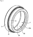
Fig. 4 is a perspective view of the rotational electric machine according to the first embodiment. -
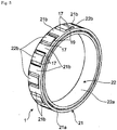
Fig. 5 is a perspective view of a rotor of the rotational electric machine according to the first embodiment. -
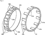
Fig. 6 is an exploded perspective view of the rotor of the rotational electric machine according to the first embodiment. -
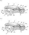
Fig. 7 is a perspective view of the rotational electric machine according to a modification of the first embodiment of the present invention when cut in the direction orthogonal to the rotational axis. -
Fig. 8 is a perspective view of the rotational electric machine according to a second embodiment of the present invention when cut in the direction orthogonal to the rotational axis. -
Fig. 9 is a perspective view of the rotational electric machine according to a modification of the second embodiment of the present invention when cut in the direction orthogonal to the rotational axis. - An embodiment of the present invention will be described below in detail with reference to the accompanying drawings.
- As illustrated in
Figs. 1 to 2B , a rotationalelectric machine 10 according to a first embodiment of the present invention is a brushless winding field rotationalelectric machine 10 positioned between a starting device 4 and acase 5 enclosing the starting device 4. The rotationalelectric machine 10 includes at least astator 3, afield coil 2, and arotor 1. In the first embodiment, for example, the rotationalelectric machine 10 is disposed between anengine 8 and atransmission 9 along a rotational axis 7, but is not limited to such disposition. For example, the rotationalelectric machine 10 may be replaced with an alternator or may be disposed at an optional position such as a position between thetransmission 9 and a wheel. - The
stator 3 has a cylindrical member non-rotatably fixed and held to thecase 5 and including a plurality of slots for winding an alternating-current coil 14. The stator includes the alternating-current coil 14 and generates a rotation magnetic field by alternating current flowing through the alternating-current coil 14. - The
field coil 2 is shifted relative to thestator 3 and therotor 1 in the rotational axis 7. Thefield coil 2 is fixed and held to thecase 5 on thetransmission 9 side of thestator 3, and excited by direct current. Afield core 6 includes thefield coil 2. Thefield coil 2 may be shifted to the engine side of thestator 3 through asecond air gap 12, not to thetransmission 9 side of thestator 3, relative to thestator 3 and therotor 1 in the rotational axis 7 (refer to aregion 89 illustrated with a dashed and single-dotted line inFig. 1 ). - The
rotor 1 is fixed to the outer periphery of the starting device 4. The outer peripheral surface of therotor 1 faces the inner peripheral surface of thestator 3 and an end face of therotor 1 on the transmission side faces an end face of thefield coil 2 on the engine side. Therotor 1 is held rotatably relative to thestator 3 and thefield coil 2 about the rotational axis 7 - As illustrated in
Fig. 1 , therotor 1 includes aconnection portion 31 and is connected to a synchronizedrotation member 30 configured to rotate in synchronization with an output shaft of theengine 8 through theconnection portion 31. The rotational axis 7 aligns with the central axis of the output shaft of theengine 8. Accordingly, the output shaft of theengine 8 and the rotational axis 7 of the rotationalelectric machine 10 have an identical central axis. - In the first embodiment, for example, the starting device 4 is a torque converter, and the synchronized
rotation member 30 is a drive plate connected to the torque converter on the engine side thereof. The starting device 4 may be a frictional clutch device. - As illustrated in
Fig. 2 , theconnection portion 31 is provided on a facingsurface 221 to the synchronizedrotation member 30 of therotor 1. Specifically, theconnection portion 31 has a bolt shape protruding from the facingsurface 221 in an extending direction of the rotational axis 7. Theconnection portion 31 is disposed on the facingsurface 221 of a secondcircular ring portion 22a to be described later at a secondmagnetic pole 22 of therotor 1 and on the inner side of aconvex portion 22b to be described later in the radial direction of the rotational axis 7. In the first embodiment, for example, therotor 1 includes a plurality ofconnection portions 31 disposed at intervals in the circumferential direction with respect to the rotational axis 7. - A
first air gap 11 is formed between thestator 3 and therotor 1 so that magnetic flux is transferred between thestator 3 and therotor 1. Thefirst air gap 11 extends in an axial direction of the rotational axis 7 between the inner peripheral surface of thestator 3 and the outer peripheral surface of therotor 1. - The
second air gap 12 is formed between thefield core 6 and therotor 1 so that magnetic flux is transferred between thefield coil 2 and therotor 1. Thesecond air gap 12 extends in the radial direction orthogonal to the axial direction of the rotational axis 7 between the end face of therotor 1 on the transmission side in the axial direction of the rotational axis 7 and an end face of thefield core 6 on the engine side. - Accordingly, the
field coil 2 is shifted in parallel relative to therotor 1 in the axial direction of the rotational axis 7 through thesecond air gap 12. - As illustrated in
Figs. 3 to 6 , therotor 1 is formed by combining a firstmagnetic pole 21 and the secondmagnetic pole 22. A cross-sectional view taken along line A-A inFig. 3 is a cross-sectional view of the rotationalelectric machine 10, the starting device 4, and the like at the center inFig. 1 .Figs. 5 and6 omit illustration of theconnection portion 31. - The first
magnetic pole 21 is made of a soft magnetic body such as iron, and includes a plurality ofclaw portions 21b each having, for example, a rectangular thin plate shape and protruding from a firstcircular ring portion 21a in the axial direction of the rotational axis 7. Theclaw portions 21b are disposed at constant intervals, for example, at equal intervals in the circumferential direction, and have equal lengths in the axial direction of the rotational axis 7. The outer peripheral surface of eachclaw portion 21b is disposed along the outer peripheral surface of the firstcircular ring portion 21a. Theclaw portion 21b does not contact the secondmagnetic pole 22 even when the firstmagnetic pole 21 and the secondmagnetic pole 22 are combined with each other, and aradial direction gap 16 is formed in the radial direction of the rotational axis 7. - The second
magnetic pole 22 is made of a soft magnetic body such as iron and disposed on an inner side of the first magnetic pole (in the present embodiment, the firstcircular ring portion 21a) through theradial direction gap 16 in a radial direction of the rotational axis 7. The secondmagnetic pole 22 includes a secondcircular ring portion 22a disposed partially overlapping the first magnetic pole (in the present embodiment, the firstcircular ring portion 21a) and a plurality ofconvex portions 22b. Each of the plurality ofconvex portions 22b, which has a rectangular plate shape for example, protrudes from an outer peripheral surface of the secondcircular ring portion 22a in the radial direction of the rotational axis 7 and has acircumferential direction gap 17 in a circumferential direction of the rotational axis 7. Theconvex portions 22b are disposed at constant intervals, for example, at equal intervals in the circumferential direction, and have equal heights in the radial direction of the rotational axis 7. Theconvex portions 22b have equal lengths in the axial direction of the rotational axis 7 and are shorter than theclaw portions 21b. The outer peripheral surface of eachconvex portion 22b is disposed on one circle having a center at the rotational axis of therotor 1. Eachconvex portion 22b extends to an end edge of the secondcircular ring portion 22a on the engine side to form a first leading end lock portion 22c, but does not extend to an end edge of the secondcircular ring portion 22a on the transmission side to form a circular ringfitting portion 22d having a small width with noconvex portion 22b. The firstmagnetic pole 21 is moved relative to the secondmagnetic pole 22 in the axial direction of the rotational axis 7 to insert eachclaw portion 21b of the firstmagnetic pole 21 into a middle part of thecircumferential direction gap 17 between theconvex portions 22b adjacent thereto so that theclaw portions 21b and theconvex portions 22b are alternately arranged in the circumferential direction of the rotational axis 7. In this case, the firstcircular ring portion 21a of the firstmagnetic pole 21 can be disposed on the outside of thefitting portion 22d with theradial direction gap 16 interposed therebetween. In the assembled state as illustrated inFig. 5 , anaxial direction gap 19 is formed between theconvex portions 22b and the firstcircular ring portion 21a, thecircumferential direction gap 17 is formed in the circumferential direction of the rotational axis 7 between eachclaw portion 21b and the correspondingconvex portion 22b of the secondmagnetic pole 22, and theradial direction gap 16 is formed in the radial direction of the rotational axis 7. With this configuration, the firstmagnetic pole 21 and the secondmagnetic pole 22 are maintained in a non-contact manner through a non-magnetic body member disposed between the firstmagnetic pole 21 and the secondmagnetic pole 22 in the radial direction of the rotational axis 7. - In the rotational
electric machine 10 configured as described above, field coilmagnetic flux 15 occurs when thefield coil 2 is energized. The field coilmagnetic flux 15 starts from thefield core 6 and returns to thefield core 6 through asecond air gap 12, the firstmagnetic pole 21 of therotor 1, thefirst air gap 11, thestator 3, thefirst air gap 11, the secondmagnetic pole 22 of therotor 1, and thesecond air gap 12. In this case, for example, when thefield coil 2 is energized with direct current, the field coilmagnetic flux 15 is generated and the firstmagnetic pole 21 and the secondmagnetic pole 22 are magnetized, for example, as a north pole and a south pole, respectively. - The following describes a case in which the rotational
electric machine 10 as a starter executes a start function. An inverter (not illustrated) is driven based on a start command of theengine 8 to cause three-phase alternating current to flow through thestator 3 and magnetize thestator 3, and cause current to flow through thefield coil 2. Current is caused to flow through thefield coil 2, thereby exciting the firstmagnetic pole 21 and the secondmagnetic pole 22 of therotor 1. As a result, therotor 1 starts rotation relative to thestator 3, and electromotive force having induction voltage is generated at thestator 3. - Thereafter, when the induction voltage increases in accordance with the rotational speed of the
rotor 1 and the rotational speed reaches an initial explosion rotational speed lower than an idling rotational speed corresponding to idling of theengine 8, which completes start of theengine 8, the drive of the inverter is stopped. Since then, transition is automatically made to a power generation mode in which the rotationalelectric machine 10 executes an electric generation function as an electric generator to hold predetermined induction voltage (request voltage). - In the power generation mode, the excitation current is adjusted so that the induction voltage is constant at the predetermined induction voltage to continuously excite the
field coil 2. The excitation current is adjusted so that the magnetization force of the rotor decreases as the rotational speed increases and the induction voltage is kept constant. When thefield coil 2 is not excited, the advance of the three-phase alternating current is adjusted by the inverter so that the induction voltage is constant at the predetermined induction voltage. Further, the above-described two methods may be combined to achieve the adjustment. With this control, the rotationalelectric machine 10 functions as an electric generator when therotor 1 rotates. - As a result, when connected to the
engine 8, the rotationalelectric machine 10 can start the engine and function as a generator (electric generator) in traveling. - In the rotational
electric machine 10 according to the first embodiment, therotor 1 includes theconnection portion 31 to be connected to thesynchronized rotation member 30. Thus, any member for connecting the starting device 4 and thesynchronized rotation member 30 with each other can be omitted to achieve the rotationalelectric machine 10 in which increase in the number of components is reduced. - The
connection portion 31 is disposed on the facingsurface 221 of the secondcircular ring portion 22a and on the inner side of theconvex portion 22b in the radial direction of the rotational axis 7. Accordingly, theconnection portion 31 can be provided to therotor 1 while the magnetic path of the second magnetic pole is prevented from narrowing. - The
connection portion 31 is not limited to a bolt shape, but may have a nut shape as illustrated inFig. 7 . In other words, theconnection portion 31 may have a bolt shape or a nut shape. This increases the freedom of designing of the rotationalelectric machine 10. - The
rotor 1 includes the plurality ofconnection portions 31 disposed at intervals in the circumferential direction with respect to the rotational axis 7. Accordingly, therotor 1 can be more reliably connected to thesynchronized rotation member 30. Only at least oneconnection portion 31 needs to be provided. - According to a second embodiment of the present invention, an annular stepped
portion 32 may be provided to theconnection portion 31 in the configuration of the first embodiment as illustrated inFigs. 8 and9 . - More specifically, as illustrated in
Fig. 8 , when theconnection portion 31 has a bolt shape, the steppedportion 32 is provided at an end portion of theconnection portion 31 on the secondcircular ring portion 22a side. As illustrated inFig. 9 , when theconnection portion 31 has a nut shape, the steppedportion 32 is provided around anopening 33 on the facingsurface 221 of the secondcircular ring portion 22a. - With this configuration, it is possible to increase the strength of the
connection portion 31 and prevent a magnetic short circuit from occurring between the first magnetic pole and the second magnetic pole when theconnection portion 31 is made of a magnetic body such as iron. Accordingly, therotor 1 can be more reliably connected to thesynchronized rotation member 30 while adverse magnetic influence is prevented. - Any embodiments or modifications among various embodiments or modifications described above may be combined with each other as appropriate to achieve effects of each embodiment or modification. It is possible to combine embodiments, examples, or an embodiment and an example, and it is also possible to combine features in different embodiments or examples.
- A rotational electric machine according to the aspect of the present invention is applicable to, for example, a vehicle or a power generation device.
-
- 1: Rotor
- 2: Field coil
- 3: Stator
- 4: Starting device
- 5: Case
- 6: Field core
- 7: Rotational axis
- 8: Engine
- 9: transmission
- 10: Brushless winding field rotational electric machine
- 11: First air gap
- 12: Second air gap
- 14: Alternating-current coil
- 15: Field coil magnetic flux
- 16: Radial direction gap
- 17: Circumferential direction gap
- 19: Axial direction gap
- 21: First magnetic pole
- 21a: First circular ring portion
- 21b: claw portion
- 22: Second magnetic pole
- 22a: Second circular ring portion
- 22b: Convex portion
- 22c: Second leading end lock portion
- 22d: Fitting portion
- 221: Facing surface
- 30: Synchronized rotation member
- 31: Connection portion
- 32: Stepped portion
- 33: Opening
- 89: Region of field coil shifted to engine side of stator
Claims (3)
- Arrangement comprising a starting device (4) being a torque converter or a frictional clutch device, a case (5) enclosing the starting device (4) and a brushless winding field rotational electric machine (10) positioned between the starting device (4) and the case (5), the rotational electric machine (10) comprising:a stator (3), which is held to the case (5), including an alternating-current coil (14) configured to generate a rotation magnetic field by alternating current;a field core (6), which is held to the case (5), including a field coil (2) to be excited by direct current; anda rotor (1) disposed on an outer periphery of the starting device (4) and rotatably held about a rotational axis (7) thereof relative to the stator (3) and the field coil (2), whereinthe rotor (1) includes a connection portion (31) to be connected to a synchronized rotation member (30) connected to the starting device (4) on an engine side thereof and configured to rotate in synchronization with an engine along the rotational axis, on a facing surface to the synchronized rotation member,the rotor (1) comprises a first magnetic pole (21) and a second magnetic pole (22), the first magnetic pole (21) and the second magnetic pole (22) are arranged without being in contact with each other, characterized in thatthe first magnetic pole (21) includes a first circular ring portion (21a) and a plurality of claw portions (21b) each protruding from the first circular ring portion (21a) in an axial direction of the rotational axis (7),the second magnetic pole (22) is disposed on an inner side of the first magnetic pole (21) through a radial direction gap (16) in a radial direction of the rotational axis (7) and includes a second circular ring portion (22a) disposed partially overlapping the first magnetic pole (21) and a plurality of convex portions (22b) each protruding from an outer peripheral surface of the second circular ring portion (22a) in the radial direction of the rotational axis (7) and each having a circumferential direction gap (17) in a circumferential direction of the rotational axis (7),each of the plurality of claw portions (21b) is inserted in the circumferential direction gap (17) so that the claw portions (21b) and the convex portions (22b) are alternately arranged in the circumferential direction of the rotational axis (7), andthe connection portion (31) is disposed on the facing surface of the second circular ring portion (22a) and on the inner side of the convex portion (22b) in the radial direction of the rotational axis (7).
- Arrangement according to claim 1, wherein
the connection portion (31) has a bolt shape or a nut shape. - Arrangement according to any one of the preceding claims, wherein
the rotor (1) includes the plurality of connection portions (31) disposed at intervals in the circumferential direction of the rotational axis (7).
Applications Claiming Priority (1)
| Application Number | Priority Date | Filing Date | Title |
|---|---|---|---|
| JP2018087325A JP7133970B2 (en) | 2018-04-27 | 2018-04-27 | Rotating electric machine |
Publications (2)
| Publication Number | Publication Date |
|---|---|
| EP3561290A1 EP3561290A1 (en) | 2019-10-30 |
| EP3561290B1 true EP3561290B1 (en) | 2021-06-02 |
Family
ID=66290268
Family Applications (1)
| Application Number | Title | Priority Date | Filing Date |
|---|---|---|---|
| EP19171298.3A Active EP3561290B1 (en) | 2018-04-27 | 2019-04-26 | Rotational electric machine |
Country Status (4)
| Country | Link |
|---|---|
| US (1) | US11133732B2 (en) |
| EP (1) | EP3561290B1 (en) |
| JP (1) | JP7133970B2 (en) |
| CN (1) | CN110417187A (en) |
Families Citing this family (1)
| Publication number | Priority date | Publication date | Assignee | Title |
|---|---|---|---|---|
| JP7141250B2 (en) * | 2018-05-31 | 2022-09-22 | 株式会社エクセディ | Rotating electric machine |
Family Cites Families (26)
| Publication number | Priority date | Publication date | Assignee | Title |
|---|---|---|---|---|
| DE3013424A1 (en) * | 1980-04-05 | 1981-10-15 | Bosch Gmbh Robert | ELECTRIC MACHINE |
| JPS5879668A (en) * | 1981-11-05 | 1983-05-13 | Nissan Motor Co Ltd | Engine starting and charging equipment |
| JP2539221B2 (en) | 1987-06-10 | 1996-10-02 | マツダ株式会社 | Engine start charging device |
| JPH01123460U (en) * | 1988-02-12 | 1989-08-22 | ||
| JPH03141819A (en) * | 1989-10-25 | 1991-06-17 | Mazda Motor Corp | Engine control device |
| JPH05153758A (en) * | 1991-11-26 | 1993-06-18 | Mitsubishi Electric Corp | Engine starter / generator |
| US5955807A (en) | 1997-04-25 | 1999-09-21 | Denso Corporation | Synchronous electric machine having auxiliary permanent magnet |
| JP3704881B2 (en) | 1997-04-25 | 2005-10-12 | 株式会社デンソー | Synchronous rotating machine with permanent magnet and driving method thereof |
| JP3981901B2 (en) | 1998-02-23 | 2007-09-26 | 株式会社名機製作所 | Rotating synchronous machine with thrust control |
| JP3445492B2 (en) | 1998-05-25 | 2003-09-08 | 三菱電機株式会社 | Claw pole type brushless generator |
| US6133702A (en) * | 1998-11-18 | 2000-10-17 | Chrysler Corporation | Multi-function vehicle starter and alternator and method therefor |
| FR2806223B1 (en) | 2000-03-10 | 2003-10-03 | Valeo Equip Electr Moteur | POLYPHASE ROTATING ELECTRIC MACHINE |
| JP2004072827A (en) | 2002-08-01 | 2004-03-04 | Tamagawa Seiki Co Ltd | Field control motor |
| FR2870055B1 (en) | 2004-04-30 | 2013-07-05 | Valeo Equip Electr Moteur | POLYPHASE ELECTRIC ROTATING ELECTRIC MACHINE FOR A MOTOR VEHICLE EQUIPPED WITH MAGNETIC MEANS FOR MONITORING THE ROTATION OF THE ROTOR OF IMPROVED MECHANICAL RESISTANCE |
| FR2890798A1 (en) | 2005-09-13 | 2007-03-16 | Valeo Equip Electr Moteur | STATOR FOR AN ALTERNATOR OR ALTERNO-STARTER TYPE POLYPHASE ELECTRICAL ROTATING MACHINE |
| WO2008092426A2 (en) | 2007-01-29 | 2008-08-07 | Luk Lamellen Und Kupplungsbau Beteiligungs Kg | Drive train having a wet starting clutch for hybrid applications |
| WO2012029707A1 (en) | 2010-09-03 | 2012-03-08 | 三菱電機株式会社 | Hybrid automobile |
| JP5673640B2 (en) * | 2012-02-29 | 2015-02-18 | アイシン・エィ・ダブリュ株式会社 | Hybrid excitation type rotating electric machine |
| IN2014DN09313A (en) * | 2012-04-27 | 2015-07-10 | Japan Corn Starch Co Ltd | |
| US10270306B2 (en) * | 2014-01-29 | 2019-04-23 | Denso Corporation | Motor and rotor |
| JP6207544B2 (en) | 2015-04-28 | 2017-10-04 | 株式会社平安製作所 | Drive plate and manufacturing method thereof |
| US9434176B1 (en) | 2015-06-29 | 2016-09-06 | Xerox Corporation | Vector compensation for inoperative ink-jets in composite colors |
| JP6614986B2 (en) | 2016-02-02 | 2019-12-04 | 株式会社エクセディ | Power transmission device with rotating electric machine |
| JP6714458B2 (en) * | 2016-07-15 | 2020-06-24 | 株式会社エクセディ | Torque converter and power transmission device |
| JP6713865B2 (en) | 2016-07-15 | 2020-06-24 | 株式会社エクセディ | Torque converter |
| JP7195923B2 (en) | 2017-01-27 | 2022-12-26 | 株式会社エクセディ | Rotating electric machine |
-
2018
- 2018-04-27 JP JP2018087325A patent/JP7133970B2/en active Active
-
2019
- 2019-04-23 US US16/392,148 patent/US11133732B2/en active Active
- 2019-04-26 CN CN201910345728.0A patent/CN110417187A/en active Pending
- 2019-04-26 EP EP19171298.3A patent/EP3561290B1/en active Active
Non-Patent Citations (1)
| Title |
|---|
| None * |
Also Published As
| Publication number | Publication date |
|---|---|
| JP2019193527A (en) | 2019-10-31 |
| CN110417187A (en) | 2019-11-05 |
| US11133732B2 (en) | 2021-09-28 |
| JP7133970B2 (en) | 2022-09-09 |
| US20190334423A1 (en) | 2019-10-31 |
| EP3561290A1 (en) | 2019-10-30 |
Similar Documents
| Publication | Publication Date | Title |
|---|---|---|
| JPH10126985A (en) | Permanent magnet rotating electric machine and electric vehicle using permanent magnet rotating electric machine | |
| US20130154410A1 (en) | Hybrid automobile | |
| EP4195458B1 (en) | Rotor, electric motor, powertrain and vehicle | |
| US10985638B2 (en) | Rotary electric machine | |
| WO2017126297A1 (en) | Rotary electric machine | |
| EP3562008B1 (en) | Rotational electric machine | |
| EP3561290B1 (en) | Rotational electric machine | |
| US10886799B2 (en) | Rotary electric machine | |
| US10848041B2 (en) | Rotating electric machine | |
| US11146138B2 (en) | Rotating electrical machine | |
| JP7215917B2 (en) | Rotating electric machine | |
| US10923970B2 (en) | Rotary electric machine having magnetic flux supplied from a field coil | |
| US20220337143A1 (en) | Rotor of rotary electric machine | |
| JPH104660A (en) | Ac generator | |
| JP7141249B2 (en) | Rotating electric machine |
Legal Events
| Date | Code | Title | Description |
|---|---|---|---|
| PUAI | Public reference made under article 153(3) epc to a published international application that has entered the european phase |
Free format text: ORIGINAL CODE: 0009012 |
|
| STAA | Information on the status of an ep patent application or granted ep patent |
Free format text: STATUS: THE APPLICATION HAS BEEN PUBLISHED |
|
| AK | Designated contracting states |
Kind code of ref document: A1 Designated state(s): AL AT BE BG CH CY CZ DE DK EE ES FI FR GB GR HR HU IE IS IT LI LT LU LV MC MK MT NL NO PL PT RO RS SE SI SK SM TR |
|
| AX | Request for extension of the european patent |
Extension state: BA ME |
|
| STAA | Information on the status of an ep patent application or granted ep patent |
Free format text: STATUS: REQUEST FOR EXAMINATION WAS MADE |
|
| 17P | Request for examination filed |
Effective date: 20200423 |
|
| RBV | Designated contracting states (corrected) |
Designated state(s): AL AT BE BG CH CY CZ DE DK EE ES FI FR GB GR HR HU IE IS IT LI LT LU LV MC MK MT NL NO PL PT RO RS SE SI SK SM TR |
|
| GRAP | Despatch of communication of intention to grant a patent |
Free format text: ORIGINAL CODE: EPIDOSNIGR1 |
|
| STAA | Information on the status of an ep patent application or granted ep patent |
Free format text: STATUS: GRANT OF PATENT IS INTENDED |
|
| RIC1 | Information provided on ipc code assigned before grant |
Ipc: H02K 19/24 20060101ALI20200923BHEP Ipc: H02K 19/10 20060101ALI20200923BHEP Ipc: H02K 19/26 20060101ALI20200923BHEP Ipc: B60K 6/26 20071001ALN20200923BHEP Ipc: H02K 7/10 20060101ALI20200923BHEP Ipc: F02N 11/04 20060101AFI20200923BHEP Ipc: H02K 19/12 20060101ALI20200923BHEP Ipc: H02K 7/00 20060101ALI20200923BHEP Ipc: H02K 7/108 20060101ALI20200923BHEP Ipc: H02K 19/36 20060101ALN20200923BHEP |
|
| INTG | Intention to grant announced |
Effective date: 20201021 |
|
| GRAJ | Information related to disapproval of communication of intention to grant by the applicant or resumption of examination proceedings by the epo deleted |
Free format text: ORIGINAL CODE: EPIDOSDIGR1 |
|
| STAA | Information on the status of an ep patent application or granted ep patent |
Free format text: STATUS: REQUEST FOR EXAMINATION WAS MADE |
|
| GRAP | Despatch of communication of intention to grant a patent |
Free format text: ORIGINAL CODE: EPIDOSNIGR1 |
|
| STAA | Information on the status of an ep patent application or granted ep patent |
Free format text: STATUS: GRANT OF PATENT IS INTENDED |
|
| INTC | Intention to grant announced (deleted) | ||
| RIC1 | Information provided on ipc code assigned before grant |
Ipc: H02K 19/24 20060101ALI20201124BHEP Ipc: H02K 19/26 20060101ALI20201124BHEP Ipc: H02K 19/10 20060101ALI20201124BHEP Ipc: H02K 7/108 20060101ALI20201124BHEP Ipc: F02N 11/04 20060101AFI20201124BHEP Ipc: H02K 19/36 20060101ALN20201124BHEP Ipc: B60K 6/26 20071001ALN20201124BHEP Ipc: H02K 19/12 20060101ALI20201124BHEP Ipc: H02K 7/00 20060101ALI20201124BHEP Ipc: H02K 7/10 20060101ALI20201124BHEP |
|
| INTG | Intention to grant announced |
Effective date: 20201210 |
|
| GRAS | Grant fee paid |
Free format text: ORIGINAL CODE: EPIDOSNIGR3 |
|
| GRAA | (expected) grant |
Free format text: ORIGINAL CODE: 0009210 |
|
| STAA | Information on the status of an ep patent application or granted ep patent |
Free format text: STATUS: THE PATENT HAS BEEN GRANTED |
|
| REG | Reference to a national code |
Ref country code: CH Ref legal event code: EP |
|
| AK | Designated contracting states |
Kind code of ref document: B1 Designated state(s): AL AT BE BG CH CY CZ DE DK EE ES FI FR GB GR HR HU IE IS IT LI LT LU LV MC MK MT NL NO PL PT RO RS SE SI SK SM TR |
|
| REG | Reference to a national code |
Ref country code: GB Ref legal event code: FG4D |
|
| REG | Reference to a national code |
Ref country code: AT Ref legal event code: REF Ref document number: 1398667 Country of ref document: AT Kind code of ref document: T Effective date: 20210615 |
|
| REG | Reference to a national code |
Ref country code: IE Ref legal event code: FG4D |
|
| REG | Reference to a national code |
Ref country code: DE Ref legal event code: R096 Ref document number: 602019004995 Country of ref document: DE |
|
| REG | Reference to a national code |
Ref country code: LT Ref legal event code: MG9D |
|
| PG25 | Lapsed in a contracting state [announced via postgrant information from national office to epo] |
Ref country code: BG Free format text: LAPSE BECAUSE OF FAILURE TO SUBMIT A TRANSLATION OF THE DESCRIPTION OR TO PAY THE FEE WITHIN THE PRESCRIBED TIME-LIMIT Effective date: 20210902 Ref country code: FI Free format text: LAPSE BECAUSE OF FAILURE TO SUBMIT A TRANSLATION OF THE DESCRIPTION OR TO PAY THE FEE WITHIN THE PRESCRIBED TIME-LIMIT Effective date: 20210602 Ref country code: HR Free format text: LAPSE BECAUSE OF FAILURE TO SUBMIT A TRANSLATION OF THE DESCRIPTION OR TO PAY THE FEE WITHIN THE PRESCRIBED TIME-LIMIT Effective date: 20210602 Ref country code: LT Free format text: LAPSE BECAUSE OF FAILURE TO SUBMIT A TRANSLATION OF THE DESCRIPTION OR TO PAY THE FEE WITHIN THE PRESCRIBED TIME-LIMIT Effective date: 20210602 |
|
| REG | Reference to a national code |
Ref country code: NL Ref legal event code: MP Effective date: 20210602 |
|
| REG | Reference to a national code |
Ref country code: AT Ref legal event code: MK05 Ref document number: 1398667 Country of ref document: AT Kind code of ref document: T Effective date: 20210602 |
|
| PG25 | Lapsed in a contracting state [announced via postgrant information from national office to epo] |
Ref country code: GR Free format text: LAPSE BECAUSE OF FAILURE TO SUBMIT A TRANSLATION OF THE DESCRIPTION OR TO PAY THE FEE WITHIN THE PRESCRIBED TIME-LIMIT Effective date: 20210903 Ref country code: SE Free format text: LAPSE BECAUSE OF FAILURE TO SUBMIT A TRANSLATION OF THE DESCRIPTION OR TO PAY THE FEE WITHIN THE PRESCRIBED TIME-LIMIT Effective date: 20210602 Ref country code: RS Free format text: LAPSE BECAUSE OF FAILURE TO SUBMIT A TRANSLATION OF THE DESCRIPTION OR TO PAY THE FEE WITHIN THE PRESCRIBED TIME-LIMIT Effective date: 20210602 Ref country code: PL Free format text: LAPSE BECAUSE OF FAILURE TO SUBMIT A TRANSLATION OF THE DESCRIPTION OR TO PAY THE FEE WITHIN THE PRESCRIBED TIME-LIMIT Effective date: 20210602 Ref country code: LV Free format text: LAPSE BECAUSE OF FAILURE TO SUBMIT A TRANSLATION OF THE DESCRIPTION OR TO PAY THE FEE WITHIN THE PRESCRIBED TIME-LIMIT Effective date: 20210602 Ref country code: NO Free format text: LAPSE BECAUSE OF FAILURE TO SUBMIT A TRANSLATION OF THE DESCRIPTION OR TO PAY THE FEE WITHIN THE PRESCRIBED TIME-LIMIT Effective date: 20210902 |
|
| PG25 | Lapsed in a contracting state [announced via postgrant information from national office to epo] |
Ref country code: SK Free format text: LAPSE BECAUSE OF FAILURE TO SUBMIT A TRANSLATION OF THE DESCRIPTION OR TO PAY THE FEE WITHIN THE PRESCRIBED TIME-LIMIT Effective date: 20210602 Ref country code: ES Free format text: LAPSE BECAUSE OF FAILURE TO SUBMIT A TRANSLATION OF THE DESCRIPTION OR TO PAY THE FEE WITHIN THE PRESCRIBED TIME-LIMIT Effective date: 20210602 Ref country code: EE Free format text: LAPSE BECAUSE OF FAILURE TO SUBMIT A TRANSLATION OF THE DESCRIPTION OR TO PAY THE FEE WITHIN THE PRESCRIBED TIME-LIMIT Effective date: 20210602 Ref country code: SM Free format text: LAPSE BECAUSE OF FAILURE TO SUBMIT A TRANSLATION OF THE DESCRIPTION OR TO PAY THE FEE WITHIN THE PRESCRIBED TIME-LIMIT Effective date: 20210602 Ref country code: PT Free format text: LAPSE BECAUSE OF FAILURE TO SUBMIT A TRANSLATION OF THE DESCRIPTION OR TO PAY THE FEE WITHIN THE PRESCRIBED TIME-LIMIT Effective date: 20211004 Ref country code: NL Free format text: LAPSE BECAUSE OF FAILURE TO SUBMIT A TRANSLATION OF THE DESCRIPTION OR TO PAY THE FEE WITHIN THE PRESCRIBED TIME-LIMIT Effective date: 20210602 Ref country code: RO Free format text: LAPSE BECAUSE OF FAILURE TO SUBMIT A TRANSLATION OF THE DESCRIPTION OR TO PAY THE FEE WITHIN THE PRESCRIBED TIME-LIMIT Effective date: 20210602 Ref country code: CZ Free format text: LAPSE BECAUSE OF FAILURE TO SUBMIT A TRANSLATION OF THE DESCRIPTION OR TO PAY THE FEE WITHIN THE PRESCRIBED TIME-LIMIT Effective date: 20210602 Ref country code: AT Free format text: LAPSE BECAUSE OF FAILURE TO SUBMIT A TRANSLATION OF THE DESCRIPTION OR TO PAY THE FEE WITHIN THE PRESCRIBED TIME-LIMIT Effective date: 20210602 |
|
| REG | Reference to a national code |
Ref country code: DE Ref legal event code: R097 Ref document number: 602019004995 Country of ref document: DE |
|
| PLBE | No opposition filed within time limit |
Free format text: ORIGINAL CODE: 0009261 |
|
| STAA | Information on the status of an ep patent application or granted ep patent |
Free format text: STATUS: NO OPPOSITION FILED WITHIN TIME LIMIT |
|
| PG25 | Lapsed in a contracting state [announced via postgrant information from national office to epo] |
Ref country code: DK Free format text: LAPSE BECAUSE OF FAILURE TO SUBMIT A TRANSLATION OF THE DESCRIPTION OR TO PAY THE FEE WITHIN THE PRESCRIBED TIME-LIMIT Effective date: 20210602 |
|
| 26N | No opposition filed |
Effective date: 20220303 |
|
| PG25 | Lapsed in a contracting state [announced via postgrant information from national office to epo] |
Ref country code: AL Free format text: LAPSE BECAUSE OF FAILURE TO SUBMIT A TRANSLATION OF THE DESCRIPTION OR TO PAY THE FEE WITHIN THE PRESCRIBED TIME-LIMIT Effective date: 20210602 |
|
| PG25 | Lapsed in a contracting state [announced via postgrant information from national office to epo] |
Ref country code: IT Free format text: LAPSE BECAUSE OF FAILURE TO SUBMIT A TRANSLATION OF THE DESCRIPTION OR TO PAY THE FEE WITHIN THE PRESCRIBED TIME-LIMIT Effective date: 20210602 |
|
| REG | Reference to a national code |
Ref country code: CH Ref legal event code: PL |
|
| REG | Reference to a national code |
Ref country code: BE Ref legal event code: MM Effective date: 20220430 |
|
| PG25 | Lapsed in a contracting state [announced via postgrant information from national office to epo] |
Ref country code: MC Free format text: LAPSE BECAUSE OF FAILURE TO SUBMIT A TRANSLATION OF THE DESCRIPTION OR TO PAY THE FEE WITHIN THE PRESCRIBED TIME-LIMIT Effective date: 20210602 Ref country code: LU Free format text: LAPSE BECAUSE OF NON-PAYMENT OF DUE FEES Effective date: 20220426 Ref country code: LI Free format text: LAPSE BECAUSE OF NON-PAYMENT OF DUE FEES Effective date: 20220430 Ref country code: FR Free format text: LAPSE BECAUSE OF NON-PAYMENT OF DUE FEES Effective date: 20220430 Ref country code: CH Free format text: LAPSE BECAUSE OF NON-PAYMENT OF DUE FEES Effective date: 20220430 |
|
| PG25 | Lapsed in a contracting state [announced via postgrant information from national office to epo] |
Ref country code: BE Free format text: LAPSE BECAUSE OF NON-PAYMENT OF DUE FEES Effective date: 20220430 |
|
| PG25 | Lapsed in a contracting state [announced via postgrant information from national office to epo] |
Ref country code: IE Free format text: LAPSE BECAUSE OF NON-PAYMENT OF DUE FEES Effective date: 20220426 |
|
| GBPC | Gb: european patent ceased through non-payment of renewal fee |
Effective date: 20230426 |
|
| PG25 | Lapsed in a contracting state [announced via postgrant information from national office to epo] |
Ref country code: GB Free format text: LAPSE BECAUSE OF NON-PAYMENT OF DUE FEES Effective date: 20230426 |
|
| PG25 | Lapsed in a contracting state [announced via postgrant information from national office to epo] |
Ref country code: GB Free format text: LAPSE BECAUSE OF NON-PAYMENT OF DUE FEES Effective date: 20230426 |
|
| PG25 | Lapsed in a contracting state [announced via postgrant information from national office to epo] |
Ref country code: HU Free format text: LAPSE BECAUSE OF FAILURE TO SUBMIT A TRANSLATION OF THE DESCRIPTION OR TO PAY THE FEE WITHIN THE PRESCRIBED TIME-LIMIT; INVALID AB INITIO Effective date: 20190426 |
|
| PG25 | Lapsed in a contracting state [announced via postgrant information from national office to epo] |
Ref country code: MK Free format text: LAPSE BECAUSE OF FAILURE TO SUBMIT A TRANSLATION OF THE DESCRIPTION OR TO PAY THE FEE WITHIN THE PRESCRIBED TIME-LIMIT Effective date: 20210602 Ref country code: CY Free format text: LAPSE BECAUSE OF FAILURE TO SUBMIT A TRANSLATION OF THE DESCRIPTION OR TO PAY THE FEE WITHIN THE PRESCRIBED TIME-LIMIT Effective date: 20210602 |
|
| PG25 | Lapsed in a contracting state [announced via postgrant information from national office to epo] |
Ref country code: TR Free format text: LAPSE BECAUSE OF FAILURE TO SUBMIT A TRANSLATION OF THE DESCRIPTION OR TO PAY THE FEE WITHIN THE PRESCRIBED TIME-LIMIT Effective date: 20210602 |
|
| PG25 | Lapsed in a contracting state [announced via postgrant information from national office to epo] |
Ref country code: MT Free format text: LAPSE BECAUSE OF FAILURE TO SUBMIT A TRANSLATION OF THE DESCRIPTION OR TO PAY THE FEE WITHIN THE PRESCRIBED TIME-LIMIT Effective date: 20210602 |
|
| PGFP | Annual fee paid to national office [announced via postgrant information from national office to epo] |
Ref country code: DE Payment date: 20250305 Year of fee payment: 7 |