EP3561240A1 - Carbon seal - Google Patents
Carbon seal Download PDFInfo
- Publication number
- EP3561240A1 EP3561240A1 EP19171675.2A EP19171675A EP3561240A1 EP 3561240 A1 EP3561240 A1 EP 3561240A1 EP 19171675 A EP19171675 A EP 19171675A EP 3561240 A1 EP3561240 A1 EP 3561240A1
- Authority
- EP
- European Patent Office
- Prior art keywords
- seal
- distance
- axial end
- carbon
- seal surface
- Prior art date
- Legal status (The legal status is an assumption and is not a legal conclusion. Google has not performed a legal analysis and makes no representation as to the accuracy of the status listed.)
- Granted
Links
Images


Classifications
-
- F—MECHANICAL ENGINEERING; LIGHTING; HEATING; WEAPONS; BLASTING
- F01—MACHINES OR ENGINES IN GENERAL; ENGINE PLANTS IN GENERAL; STEAM ENGINES
- F01D—NON-POSITIVE DISPLACEMENT MACHINES OR ENGINES, e.g. STEAM TURBINES
- F01D25/00—Component parts, details, or accessories, not provided for in, or of interest apart from, other groups
- F01D25/18—Lubricating arrangements
- F01D25/183—Sealing means
-
- F—MECHANICAL ENGINEERING; LIGHTING; HEATING; WEAPONS; BLASTING
- F16—ENGINEERING ELEMENTS AND UNITS; GENERAL MEASURES FOR PRODUCING AND MAINTAINING EFFECTIVE FUNCTIONING OF MACHINES OR INSTALLATIONS; THERMAL INSULATION IN GENERAL
- F16J—PISTONS; CYLINDERS; SEALINGS
- F16J15/00—Sealings
- F16J15/16—Sealings between relatively-moving surfaces
- F16J15/164—Sealings between relatively-moving surfaces the sealing action depending on movements; pressure difference, temperature or presence of leaking fluid
-
- F—MECHANICAL ENGINEERING; LIGHTING; HEATING; WEAPONS; BLASTING
- F16—ENGINEERING ELEMENTS AND UNITS; GENERAL MEASURES FOR PRODUCING AND MAINTAINING EFFECTIVE FUNCTIONING OF MACHINES OR INSTALLATIONS; THERMAL INSULATION IN GENERAL
- F16J—PISTONS; CYLINDERS; SEALINGS
- F16J15/00—Sealings
- F16J15/16—Sealings between relatively-moving surfaces
- F16J15/34—Sealings between relatively-moving surfaces with slip-ring pressed against a more or less radial face on one member
- F16J15/3496—Sealings between relatively-moving surfaces with slip-ring pressed against a more or less radial face on one member use of special materials
-
- F—MECHANICAL ENGINEERING; LIGHTING; HEATING; WEAPONS; BLASTING
- F05—INDEXING SCHEMES RELATING TO ENGINES OR PUMPS IN VARIOUS SUBCLASSES OF CLASSES F01-F04
- F05D—INDEXING SCHEME FOR ASPECTS RELATING TO NON-POSITIVE-DISPLACEMENT MACHINES OR ENGINES, GAS-TURBINES OR JET-PROPULSION PLANTS
- F05D2250/00—Geometry
- F05D2250/30—Arrangement of components
- F05D2250/31—Arrangement of components according to the direction of their main axis or their axis of rotation
- F05D2250/314—Arrangement of components according to the direction of their main axis or their axis of rotation the axes being inclined in relation to each other
Definitions
- the present disclosure relates to a seal, and more particularly to a carbon seal.
- Carbon seals are frequently used in a number of applications, such as for line replaceable units and in connection with an aircraft gas turbine engines, industrial gas turbines, or other machines. Moreover, carbon seals are used to create seals for both the input and output shafts of a gear box for driving the line replaceable units (LRU). Finally, the seal is used on the LRU itself. Carbon seals are known for their ability to maintain performance under varying thermal and pressure loads.
- a seal in one exemplary embodiment, includes a carbon seal that is disposed about an axis and extends between a first axial end and a second axial end.
- the second axial end includes a seal surface and a radially outer edge of the seal surface is axially spaced from a radially inner edge of the seal surface along the axis.
- the radially inner edge is spaced a first distance from the first axial end.
- the radially outer edge is spaced a second distance from the first axial end. The first distance is greater than the second distance to define the seal surface as convex.
- the first distance at the radially inner edge and the second distance at the radially outer edge are measured at the same circumferential position along the carbon seal.
- the radially inner edge is spaced a first distance from the first axial end.
- the radially outer edge is spaced a second distance from the first axial end. The first distance is less than the second distance to define the seal surface as concave.
- the first distance at the radially inner edge and the second distance at the radially outer edge are measured at the same circumferential position along the carbon seal.
- a rotary component in another exemplary embodiment, includes a first rotating disk disposed about a first axis that includes a first rotating disk seal surface.
- a first carbon seal is disposed about the first axis and extends between a first axial end and a second axial end.
- the second axial end includes a seal surface located adjacent the rotating disk seal surface.
- a radially outer edge of the seal surface is axially spaced from a radially inner edge of the seal surface along the axis.
- the radially inner edge of the seal surface is spaced a first distance from the first axial end.
- the radially outer edge of the seal surface is spaced a second distance from the first axial end. The first distance is less than the second distance to define the seal surface as concave.
- the first rotating disk includes a plurality of pumping features.
- the first distance at the radially inner edge and the second distance at the radially outer edge are measured at the same circumferential position along the first carbon seal.
- the rotary component is a line replaceable unit that has a sealed housing.
- the sealed housing includes at least one pressure relief valve.
- the radially inner edge of the seal surface is spaced a first distance from the first axial end.
- the radially outer edge of the seal surface is spaced a second distance from the first axial end. The first distance is greater than the second distance to define the seal surface as convex.
- the first rotating disk includes a plurality of pumping features.
- the first distance at the radially inner edge and the second distance at the radially outer edge are measured at the same circumferential position along the carbon seal.
- a second rotating disk is disposed about a second axis that includes a second rotating disk seal surface.
- a second carbon seal is disposed about the second axis and extends between a first axial end and a second axial end.
- the second axial end includes a second seal surface located adjacent the second rotating disk seal surface.
- a radially outer edge of the second seal surface is axially spaced from a radially inner edge of the second seal surface along the second axis.
- the radially inner edge on the second carbon seal is spaced a first distance from the first axial end of the second carbon seal.
- the radially outer edge of the second carbon seal is spaced a second distance from the first axial end of the second carbon seal. The first distance is greater than the second distance.
- the first distance at the radially inner edge of the second carbon seal and the second distance at the radially outer edge of the second carbon seal are measured at the same circumferential position along the second carbon seal.
- the rotary component is a gear box.
- a method of controlling the pressure in a rotary component includes the step of rotating a first rotating disk about a first axis relative to a first carbon seal to vary a pressure in the rotary component.
- the first carbon seal is disposed about the first axis and extends between a first axial end and a second axial end.
- the second axial end includes a first seal surface located adjacent a first rotating disk seal surface on the first rotating disk.
- the first carbon seal surface includes a radially inner edge axially spaced from a radially outer edge along the first axis.
- the radially inner edge of the first carbon seal is spaced a first distance from the first axial end of the first carbon seal.
- the radially outer edge of the first carbon seal is spaced a second distance from the first axial end of the first carbon seal. The first distance is less than the second distance to define the first seal surface as concave.
- the first rotating disk includes a plurality of pumping features.
- the radially inner edge of the first carbon seal is spaced a first distance from the first axial end of the first carbon seal.
- the radially outer edge of the first carbon seal is spaced a second distance from the first axial end of the first carbon seal. The first distance is greater than the second distance to define the first seal surface as convex.
- the first rotating disk includes a plurality of pumping features.
- the method includes rotating a second rotating disk about a second axis relative to a second carbon seal to vary a pressure in the rotary component.
- the second carbon seal is disposed about the second axis and extends between a first axial end and a second axial end.
- the second axial end includes a second carbon seal surface located adjacent a second rotating disk seal surface on the second rotating disk.
- the second carbon seal surface includes a radially inner edge spaced a first distance from the first axial end of the second carbon seal.
- the radially outer edge is spaced a second distance from the first axial end of the second carbon seal.
- the first distance is greater than the second distance to define the second seal surface as convex.
- FIG. 1 schematically illustrates an example rotary component 20, such as a line replaceable unit.
- the line replaceable unit can be a generator, a starter, a pump, a compressor, and etc.
- the rotary component 20 includes a housing 22 forming an enclosure. Because the rotary component 20 is a line replaceable unit, the housing 22 is sealed to prevent damage to internal component of the rotary component 20 and includes a pressure relief valve 24 to prevent the housing 22 from becoming overly pressurized.
- the housing 22 includes an aperture 26 for accepting an input shaft 28.
- the input shaft 28 drives a rotating disk 30, which is mechanically attached to an internal shaft 32, such as a disconnect shaft, for driving the internal mechanisms of the rotary component 20 to allow the rotary component 20 to function for its intended purpose.
- the seal assembly 34 includes a seal surface 36 that interfaces with a disk seal surface 38 to form a seal between the rotating disk 30 and the seal assembly 34.
- This type of seal arrangement is generally known as a hydrodynamic seal or lift off seal.
- the seal assembly 34 is at least partially supported by the housing 22.
- the seal assembly 34 is shown in cross section in the illustrated example, the seal assembly 34 forms an annular ring around the input shaft 28 and fits within the aperture 26.
- Figure 2 illustrates another example rotary component 120, such as a gear box.
- the rotary component 120 is similar to the rotary component 20 except where described below or shown in the Figures.
- like elements between the rotary component 20 and the rotary component 120 will have the addition of a leading 1 and be followed by an "A" or "B" to indicate multiple like components.
- the rotary component 120 includes a housing 122 forming an enclosure.
- the housing 122 includes a first and second aperture 126A, 126B for accepting a first and second shaft 128A, 128B, respectively.
- one of the first and second shafts 128A, 128B could be an input shaft and the other of the first and second shafts 128A, 128B could be a drive shaft, such as a tower shaft.
- the rotary component 120 could have multiple output shafts for driving another rotary component 20.
- the first and second shafts 128A, 128B each drive a first and second rotating disk 130A, 130B, which are mechanically attached to a first and second internal shaft 132A, 132B, respectively.
- a first and second seal assembly 134A, 134B includes a first and second seal surface 136A, 136B that interfaces with a first and second disk seal surface 138A, 138B to form a seal between the first and second rotating disks 130A, 130B and the first and second seal assemblies 134A, 134B, respectively.
- the first and second seal assemblies 134A, 134B are at least partially supported by the housing 122.
- first and second seal assemblies 134A, 134B are shown in cross section in the illustrated example, the first and second seal assemblies 134A, 134B form an annular ring around the first and second shafts 128A, and 128B and fit within the first and second apertures 126A, 126B.
- housing 122 could have additional apertures and shafts with seal assemblies and rotating disks beyond the two shown in Figure 2 for driving multiple LRUs under this disclosure.
- Figure 3 illustrates an enlarged cross-sectional view of the seal assembly 34 about the axis A of rotation of the seal assembly 34.
- Figure 3 relies on the same reference numerals used in relation to Figure 1 , the description regarding Figure 3 applies equally to the first and second seal assemblies 134A, 134B and their respective surrounding structure in Figure 2 except where noted below or shown in the Figures.
- the seal assembly 34 includes a carrier 40 for supporting a carbon seal 42.
- the carbon seal 42 is located in a cavity 44 formed in the carrier 40.
- An O-ring 46 is located within the cavity 44 between a radially inner side of the carbon seal 42 and the carrier 40 to seal the carbon seal 42 relative to the carrier 40.
- a spacer 48 separates the carbon seal 42 and the O-ring 46 from a biasing member 50.
- the biasing member 50 includes a first axial end that engages the carrier 40 and a second axial end that engages the spacer 48 to bias the carbon seal 42 against the rotating disk 30.
- the rotating disk 30 includes a radially extending portion 52 having the disk seal surface 38 that interfaces with the seal surface 36 on the carbon seal 42 to form a seal between the rotating disk 30 and the carbon seal 42.
- the rotating disk 30 also includes an axially extending portion 54 that includes a splined interface 56 on a radially inner side that engages a splined interface 58 in the input shaft 28.
- the axially extending portion 54 extends fore and aft of the radially extending portion 52.
- An axial end of the rotating disk 30 includes an interface 60, such as a toothed interface, to connect the rotating disk 30 to corresponding features on the internal shaft 32.
- the bearing system 62 includes an outer race 64 fixed relative to the housing 22 and an inner race 66 that supports the rotating disk 30 and the internal shaft 32.
- a plurality of rotating bearing members 68 are located between the outer race 64 and the inner race 66.
- a journal bearing assembly 70 is located between the inner race 66 and the rotating disk 30.
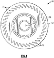
- Figure 4 is an axial view of the rotating disk 30 showing the disk seal surface 38.
- the disk seal surface 38 includes a plurality of pumping features 72 that interface with the carbon seal 42.
- the pumping features 72 which are depressions in the disk seal surface 38, interface with the carbon seal 42 to create a hydrodynamic pump that pressurizes the housing 22. Because the rotary component 20 is sealed, the more pumping action the rotating disk 30 and the carbon seal 42 create, the greater the pressure in the housing 22.
- a concavity of the seal surface 36 on the carbon seal 42 is varied.
- the seal surface 36 is convex as shown in Figure 6 .
- the seal surface 36 includes a radially inner edge 74 and a radially outer edge 78 with the radially inner edge 74 spaced a first distance D1 from a first axial end 76 of the carbon seal 42 and the radially outer edge 78 is spaced a second distance D2 from the first axial end 76.
- first distance D1 being greater than the second distance D2 and the first distance D1 and the second distance D2 are both measured at the same circumferential position along the carbon seal 42.
- the seal surface 36 forms a second axial end of the carbon seal 42.
- the seal surface 36 is concave as shown in Figure 5 .
- the radially inner edge 74 is spaced the first distance D1 from the first axial end 76 of the carbon seal 42 and the radially outer edge 78 is spaced the second distance D2 from the first axial end 76.
- the first distance D1 is less than the second distance D2 and the first distance D1 and the second distance D2 are both measured at the same circumferential position along the carbon seal 42.
- the seal surface 36 maintains an overall flatness measurement of three or less helium light bands. In another example, the seal surface 36 of Figures 5 and 6 maintain an overall flatness measurement of two or less helium light bands.
Landscapes
- Engineering & Computer Science (AREA)
- General Engineering & Computer Science (AREA)
- Mechanical Engineering (AREA)
- Mechanical Sealing (AREA)
- Sealing Devices (AREA)
Abstract
Description
- The present disclosure relates to a seal, and more particularly to a carbon seal.
- Carbon seals are frequently used in a number of applications, such as for line replaceable units and in connection with an aircraft gas turbine engines, industrial gas turbines, or other machines. Moreover, carbon seals are used to create seals for both the input and output shafts of a gear box for driving the line replaceable units (LRU). Finally, the seal is used on the LRU itself. Carbon seals are known for their ability to maintain performance under varying thermal and pressure loads.
- In one exemplary embodiment, a seal includes a carbon seal that is disposed about an axis and extends between a first axial end and a second axial end. The second axial end includes a seal surface and a radially outer edge of the seal surface is axially spaced from a radially inner edge of the seal surface along the axis.
- In a further embodiment of the above, the radially inner edge is spaced a first distance from the first axial end. The radially outer edge is spaced a second distance from the first axial end. The first distance is greater than the second distance to define the seal surface as convex.
- In a further embodiment of any of the above, the first distance at the radially inner edge and the second distance at the radially outer edge are measured at the same circumferential position along the carbon seal.
- In a further embodiment of any of the above, the radially inner edge is spaced a first distance from the first axial end. The radially outer edge is spaced a second distance from the first axial end. The first distance is less than the second distance to define the seal surface as concave.
- In a further embodiment of any of the above, the first distance at the radially inner edge and the second distance at the radially outer edge are measured at the same circumferential position along the carbon seal.
- In another exemplary embodiment, a rotary component includes a first rotating disk disposed about a first axis that includes a first rotating disk seal surface. A first carbon seal is disposed about the first axis and extends between a first axial end and a second axial end. The second axial end includes a seal surface located adjacent the rotating disk seal surface. A radially outer edge of the seal surface is axially spaced from a radially inner edge of the seal surface along the axis.
- In a further embodiment of any of the above, the radially inner edge of the seal surface is spaced a first distance from the first axial end. The radially outer edge of the seal surface is spaced a second distance from the first axial end. The first distance is less than the second distance to define the seal surface as concave. The first rotating disk includes a plurality of pumping features.
- In a further embodiment of any of the above, the first distance at the radially inner edge and the second distance at the radially outer edge are measured at the same circumferential position along the first carbon seal.
- In a further embodiment of any of the above, the rotary component is a line replaceable unit that has a sealed housing.
- In a further embodiment of any of the above, the sealed housing includes at least one pressure relief valve.
- In a further embodiment of any of the above, the radially inner edge of the seal surface is spaced a first distance from the first axial end. The radially outer edge of the seal surface is spaced a second distance from the first axial end. The first distance is greater than the second distance to define the seal surface as convex. The first rotating disk includes a plurality of pumping features.
- In a further embodiment of any of the above, the first distance at the radially inner edge and the second distance at the radially outer edge are measured at the same circumferential position along the carbon seal.
- In a further embodiment of any of the above, a second rotating disk is disposed about a second axis that includes a second rotating disk seal surface. A second carbon seal is disposed about the second axis and extends between a first axial end and a second axial end. The second axial end includes a second seal surface located adjacent the second rotating disk seal surface. A radially outer edge of the second seal surface is axially spaced from a radially inner edge of the second seal surface along the second axis.
- In a further embodiment of any of the above, the radially inner edge on the second carbon seal is spaced a first distance from the first axial end of the second carbon seal. The radially outer edge of the second carbon seal is spaced a second distance from the first axial end of the second carbon seal. The first distance is greater than the second distance.
- In a further embodiment of any of the above, the first distance at the radially inner edge of the second carbon seal and the second distance at the radially outer edge of the second carbon seal are measured at the same circumferential position along the second carbon seal.
- In a further embodiment of any of the above, the rotary component is a gear box.
- In another exemplary embodiment, a method of controlling the pressure in a rotary component includes the step of rotating a first rotating disk about a first axis relative to a first carbon seal to vary a pressure in the rotary component. The first carbon seal is disposed about the first axis and extends between a first axial end and a second axial end. The second axial end includes a first seal surface located adjacent a first rotating disk seal surface on the first rotating disk. The first carbon seal surface includes a radially inner edge axially spaced from a radially outer edge along the first axis.
- In a further embodiment of any of the above, the radially inner edge of the first carbon seal is spaced a first distance from the first axial end of the first carbon seal. The radially outer edge of the first carbon seal is spaced a second distance from the first axial end of the first carbon seal. The first distance is less than the second distance to define the first seal surface as concave. The first rotating disk includes a plurality of pumping features.
- In a further embodiment of any of the above, the radially inner edge of the first carbon seal is spaced a first distance from the first axial end of the first carbon seal. The radially outer edge of the first carbon seal is spaced a second distance from the first axial end of the first carbon seal. The first distance is greater than the second distance to define the first seal surface as convex. The first rotating disk includes a plurality of pumping features.
- In a further embodiment of any of the above, the method includes rotating a second rotating disk about a second axis relative to a second carbon seal to vary a pressure in the rotary component. The second carbon seal is disposed about the second axis and extends between a first axial end and a second axial end. The second axial end includes a second carbon seal surface located adjacent a second rotating disk seal surface on the second rotating disk. The second carbon seal surface includes a radially inner edge spaced a first distance from the first axial end of the second carbon seal. The radially outer edge is spaced a second distance from the first axial end of the second carbon seal. The first distance is greater than the second distance to define the second seal surface as convex.
-
-
Figure 1 illustrates an example rotary component. -
Figure 2 is another example rotary component. -
Figure 3 is an enlarged view of a seal assembly. -
Figure 4 is an axial view of a disk. -
Figure 5 is a cross-sectional view of an example carbon seal. -
Figure 6 is a cross-sectional view of another example carbon seal. -
Figure 1 schematically illustrates anexample rotary component 20, such as a line replaceable unit. The line replaceable unit can be a generator, a starter, a pump, a compressor, and etc. Therotary component 20 includes ahousing 22 forming an enclosure. Because therotary component 20 is a line replaceable unit, thehousing 22 is sealed to prevent damage to internal component of therotary component 20 and includes apressure relief valve 24 to prevent thehousing 22 from becoming overly pressurized. - The
housing 22 includes anaperture 26 for accepting aninput shaft 28. Theinput shaft 28 drives arotating disk 30, which is mechanically attached to aninternal shaft 32, such as a disconnect shaft, for driving the internal mechanisms of therotary component 20 to allow therotary component 20 to function for its intended purpose. - To maintain a desired pressurized state and to prevent oil loss within the
housing 22, aseal assembly 34 is used. Theseal assembly 34 includes aseal surface 36 that interfaces with adisk seal surface 38 to form a seal between therotating disk 30 and theseal assembly 34. This type of seal arrangement is generally known as a hydrodynamic seal or lift off seal. In the illustrated example, theseal assembly 34 is at least partially supported by thehousing 22. Although theseal assembly 34 is shown in cross section in the illustrated example, theseal assembly 34 forms an annular ring around theinput shaft 28 and fits within theaperture 26. -
Figure 2 illustrates anotherexample rotary component 120, such as a gear box. Therotary component 120 is similar to therotary component 20 except where described below or shown in the Figures. Moreover, like elements between therotary component 20 and therotary component 120 will have the addition of a leading 1 and be followed by an "A" or "B" to indicate multiple like components. - The
rotary component 120 includes ahousing 122 forming an enclosure. Thehousing 122 includes a first andsecond aperture second shaft 128A, 128B, respectively. Because therotary component 120 is a gear box, one of the first andsecond shafts 128A, 128B could be an input shaft and the other of the first andsecond shafts 128A, 128B could be a drive shaft, such as a tower shaft. Although only one output shaft is illustrated, therotary component 120 could have multiple output shafts for driving anotherrotary component 20. The first andsecond shafts 128A, 128B each drive a first and secondrotating disk internal shaft - To maintain the desired pressurized state within the
housing 122, a first andsecond seal assembly second seal surface disk seal surface rotating disks second seal assemblies second seal assemblies housing 122. Although the first andsecond seal assemblies second seal assemblies second shafts 128A, and 128B and fit within the first andsecond apertures - Additionally, the
housing 122 could have additional apertures and shafts with seal assemblies and rotating disks beyond the two shown inFigure 2 for driving multiple LRUs under this disclosure. -
Figure 3 illustrates an enlarged cross-sectional view of theseal assembly 34 about the axis A of rotation of theseal assembly 34. AlthoughFigure 3 relies on the same reference numerals used in relation toFigure 1 , the description regardingFigure 3 applies equally to the first andsecond seal assemblies Figure 2 except where noted below or shown in the Figures. - The
seal assembly 34 includes a carrier 40 for supporting acarbon seal 42. Thecarbon seal 42 is located in acavity 44 formed in the carrier 40. An O-ring 46 is located within thecavity 44 between a radially inner side of thecarbon seal 42 and the carrier 40 to seal thecarbon seal 42 relative to the carrier 40. Aspacer 48 separates thecarbon seal 42 and the O-ring 46 from a biasingmember 50. The biasingmember 50 includes a first axial end that engages the carrier 40 and a second axial end that engages thespacer 48 to bias thecarbon seal 42 against therotating disk 30. - The
rotating disk 30 includes aradially extending portion 52 having thedisk seal surface 38 that interfaces with theseal surface 36 on thecarbon seal 42 to form a seal between therotating disk 30 and thecarbon seal 42. Therotating disk 30 also includes anaxially extending portion 54 that includes asplined interface 56 on a radially inner side that engages asplined interface 58 in theinput shaft 28. Theaxially extending portion 54 extends fore and aft of theradially extending portion 52. An axial end of therotating disk 30 includes aninterface 60, such as a toothed interface, to connect therotating disk 30 to corresponding features on theinternal shaft 32. - While the
seal assembly 34 is principally secured relative to thehousing 22, therotating disk 30 andinternal shaft 32 are supported for rotation by a bearingsystem 62. The bearingsystem 62 includes anouter race 64 fixed relative to thehousing 22 and aninner race 66 that supports therotating disk 30 and theinternal shaft 32. A plurality ofrotating bearing members 68 are located between theouter race 64 and theinner race 66. Ajournal bearing assembly 70 is located between theinner race 66 and therotating disk 30. -
Figure 4 is an axial view of therotating disk 30 showing thedisk seal surface 38. Thedisk seal surface 38 includes a plurality of pumping features 72 that interface with thecarbon seal 42. During operation of therotary component 20, therotating disk 30 rotates and thecarbon seal 42 remains stationary. As therotating disk 30 rotates, the pumping features 72, which are depressions in thedisk seal surface 38, interface with thecarbon seal 42 to create a hydrodynamic pump that pressurizes thehousing 22. Because therotary component 20 is sealed, the more pumping action therotating disk 30 and thecarbon seal 42 create, the greater the pressure in thehousing 22. - To control an amount of pumping that the
rotating disk 30 and thecarbon seal 42 create and maintain the desired pressurized state within thehousing 22, a concavity of theseal surface 36 on thecarbon seal 42 is varied. For applications where a greater amount of pumping (reduced oil leakage) and pressure within thehousing 22 is desired, such as for gear box applications, theseal surface 36 is convex as shown inFigure 6 . In this configuration, theseal surface 36 includes a radiallyinner edge 74 and a radiallyouter edge 78 with the radiallyinner edge 74 spaced a first distance D1 from a firstaxial end 76 of thecarbon seal 42 and the radiallyouter edge 78 is spaced a second distance D2 from the firstaxial end 76. In this example, the first distance D1 being greater than the second distance D2 and the first distance D1 and the second distance D2 are both measured at the same circumferential position along thecarbon seal 42. In the illustrated example, theseal surface 36 forms a second axial end of thecarbon seal 42. - Conversely, for applications were a reduced amount of pumping is desired, such as for line replaceable units, the
seal surface 36 is concave as shown inFigure 5 . In this configuration, the radiallyinner edge 74 is spaced the first distance D1 from the firstaxial end 76 of thecarbon seal 42 and the radiallyouter edge 78 is spaced the second distance D2 from the firstaxial end 76. In this example, the first distance D1 is less than the second distance D2 and the first distance D1 and the second distance D2 are both measured at the same circumferential position along thecarbon seal 42. - In the example of
Figure 5 where theseal surface 36 is concave and in the example ofFigure 6 where theseal surface 36 is convex, theseal surface 36 maintains an overall flatness measurement of three or less helium light bands. In another example, theseal surface 36 ofFigures 5 and 6 maintain an overall flatness measurement of two or less helium light bands. - The preceding description is exemplary rather than limiting in nature. Variations and modifications to the disclosed examples may become apparent to those skilled in the art that do not necessarily depart from the scope of the invention as defined by the claims. The scope of legal protection given to this disclosure can only be determined by studying the following claims.
Claims (15)
- A seal comprising:
a carbon seal (42) disposed about an axis and extending between a first axial end and a second axial end, wherein the second axial end includes a seal surface (136) and a radially outer edge of the seal surface is axially spaced from a radially inner edge of the seal surface along the axis. - The seal of claim 1, wherein the radially inner edge is spaced a first distance from the first axial end and the radially outer edge is spaced a second distance from the first axial end and the first distance is greater than the second distance to define the seal surface as convex.
- The seal of claim 2, wherein the first distance at the radially inner edge and the second distance at the radially outer edge are measured at the same circumferential position along the carbon seal.
- The seal of claim 1, wherein the radially inner edge is spaced a first distance from the first axial end and the radially outer edge is spaced a second distance from the first axial end and the first distance is less than the second distance to define the seal surface as concave.
- The seal of claim 4, wherein the first distance at the radially inner edge and the second distance at the radially outer edge are measured at the same circumferential position along the carbon seal.
- A rotary component comprising:a first rotating disk (30) disposed about a first axis including a first rotating disk seal surface; and a seal as claimed in any preceding claim,the first carbon seal disposed about the first axis, wherein the second axial end includes the seal surface located adjacent the rotating disk seal surface.
- The rotary component of claim 6, wherein the first rotating disk includes a plurality of pumping features.
- The rotary component of claim 6 or 7, wherein the rotary component is a line replaceable unit having a sealed housing (122).
- The rotary component of claim 8, wherein the sealed housing includes at least one pressure relief valve.
- The rotary component of claim 7, 8 or 9, further comprising:a second rotating disk disposed about a second axis including a second rotating disk seal surface; anda second carbon seal disposed about the second axis and extending between a first axial end and a second axial end, wherein the second axial end includes a second seal surface located adjacent the second rotating disk seal surface and a radially outer edge of the second seal surface is axially spaced from a radially inner edge of the second seal surface along the second axis.
- The rotary component of claim 10, wherein the rotary component is a gear box.
- A method of controlling the pressure in a rotary component, the method comprising the steps of:
rotating a first rotating disk about a first axis relative to a first carbon seal to vary a pressure in the rotary component, wherein the first carbon seal is disposed about the first axis and extends between a first axial end and a second axial end and the second axial end includes a first seal surface located adjacent a first rotating disk seal surface on the first rotating disk and the first carbon seal surface includes a radially inner edge axially spaced from a radially outer edge along the first axis. - The method of claim 12, wherein the radially inner edge of the first carbon seal is spaced a first distance from the first axial end of the first carbon seal and the radially outer edge of the first carbon seal is spaced a second distance from the first axial end of the first carbon seal and the first distance is less than the second distance to define the first seal surface as concave and the first rotating disk includes a plurality of pumping features.
- The method of claim 12, wherein the radially inner edge of the first carbon seal is spaced a first distance from the first axial end of the first carbon seal and the radially outer edge of the first carbon seal is spaced a second distance from the first axial end of the first carbon seal and the first distance is greater than the second distance to define the first seal surface as convex and the first rotating disk includes a plurality of pumping features.
- The method of claim 13, further comprising:
rotating a second rotating disk about a second axis relative to a second carbon seal to vary a pressure in the rotary component, wherein the second carbon seal is disposed about the second axis and extends between a first axial end and a second axial end and the second axial end includes a second carbon seal surface located adjacent a second rotating disk seal surface on the second rotating disk and the second carbon seal surface includes a radially inner edge spaced a first distance from the first axial end of the second carbon seal and the radially outer edge spaced a second distance from the first axial end of the second carbon seal and the first distance is greater than the second distance to define the second seal surface as convex.
Applications Claiming Priority (1)
| Application Number | Priority Date | Filing Date | Title |
|---|---|---|---|
| US15/965,083 US11708909B2 (en) | 2018-04-27 | 2018-04-27 | Carbon seal |
Publications (2)
| Publication Number | Publication Date |
|---|---|
| EP3561240A1 true EP3561240A1 (en) | 2019-10-30 |
| EP3561240B1 EP3561240B1 (en) | 2020-12-09 |
Family
ID=66334212
Family Applications (1)
| Application Number | Title | Priority Date | Filing Date |
|---|---|---|---|
| EP19171675.2A Active EP3561240B1 (en) | 2018-04-27 | 2019-04-29 | Carbon seal |
Country Status (2)
| Country | Link |
|---|---|
| US (1) | US11708909B2 (en) |
| EP (1) | EP3561240B1 (en) |
Cited By (1)
| Publication number | Priority date | Publication date | Assignee | Title |
|---|---|---|---|---|
| EP3623588A1 (en) * | 2018-09-14 | 2020-03-18 | United Technologies Corporation | Shaft seal assembly for a turbine engine |
Families Citing this family (2)
| Publication number | Priority date | Publication date | Assignee | Title |
|---|---|---|---|---|
| US11143309B2 (en) * | 2018-10-09 | 2021-10-12 | Hamilton Sundstrand Corporation | Disconnect bearing and input seal for a variable frequency starter generator |
| PL3798426T3 (en) | 2019-09-27 | 2023-04-17 | Pratt & Whitney Canada Corp. | Carbon seal assembly |
Citations (4)
| Publication number | Priority date | Publication date | Assignee | Title |
|---|---|---|---|---|
| JPS5518694U (en) * | 1978-07-22 | 1980-02-06 | ||
| JPS59164869U (en) * | 1983-04-20 | 1984-11-05 | 三菱重工業株式会社 | Shaft seal device |
| EP2372100A2 (en) * | 2010-03-26 | 2011-10-05 | United Technologies Corporation | Liftoff carbon seal |
| WO2014088608A1 (en) * | 2012-12-06 | 2014-06-12 | Stein Seal Company | Windback device for a circumferential seal |
Family Cites Families (34)
| Publication number | Priority date | Publication date | Assignee | Title |
|---|---|---|---|---|
| US2646296A (en) * | 1944-06-14 | 1953-07-21 | Destoumieux Paul | Packing for use between rotatable and fixed parts |
| US2672360A (en) * | 1950-11-15 | 1954-03-16 | Garlock Packing Co | Unitary rotary seal, including both stationary and rotatable sealing rings |
| US2984505A (en) * | 1956-07-23 | 1961-05-16 | Remi J Gits Jr | Boot equipped telescoping seal |
| US3384025A (en) * | 1966-08-11 | 1968-05-21 | Sta Rite Industries | Pump construction |
| US3416808A (en) * | 1967-02-09 | 1968-12-17 | Continental Illinois Nat Bank | Floating-antirotation device |
| US3578344A (en) * | 1969-11-05 | 1971-05-11 | Rex Chainbelt Inc | Cartridge type seal having improved antirotation means |
| US3612548A (en) * | 1969-11-26 | 1971-10-12 | Borg Warner | Mechanical seal spring holder |
| US3638957A (en) * | 1970-03-19 | 1972-02-01 | Borg Warner | Mechanical seal with lubricating means |
| US3784213A (en) * | 1972-06-20 | 1974-01-08 | Innovatex Corp | Rotary face seal assembly |
| US3837658A (en) * | 1973-01-05 | 1974-09-24 | Beloit Corp | Rotary steam seal for dryer drum |
| US4269391A (en) * | 1977-04-28 | 1981-05-26 | Nippon Petrochemicals Co., Ltd. | Valve sealing device and a valve |
| US4175970A (en) | 1978-07-24 | 1979-11-27 | E. I. Du Pont De Nemours And Company | Process for sensitizing photographic silver halide emulsions |
| US4328973A (en) * | 1980-04-17 | 1982-05-11 | E. I. Du Pont De Nemours And Company | Shaft seal with fluid pressure and spring bias |
| US4415165A (en) * | 1982-12-02 | 1983-11-15 | The United States Of America As Represented By The Secretary Of The Navy | Integral elastomeric/graphite dynamic face seal |
| JPS59164869A (en) | 1983-03-10 | 1984-09-18 | 三菱重工業株式会社 | Refrigerator |
| US4605235A (en) * | 1984-09-12 | 1986-08-12 | Chandler Evans Inc. | High thrust capacity shaft seal assembly for fuel pumps |
| CA1331389C (en) * | 1985-12-20 | 1994-08-09 | John A. Hilaris | Single component seal |
| DE3740694A1 (en) * | 1987-12-01 | 1989-06-22 | Goetze Ag | MECHANICAL SEAL |
| US5020809A (en) * | 1990-02-09 | 1991-06-04 | Eg&G Sealol, Inc. | High-speed easy-maintenance split seal |
| US5947479A (en) * | 1995-03-31 | 1999-09-07 | John Crane Inc. | Mechanical seal with flexible metal diaphragm |
| WO1999027281A1 (en) * | 1997-11-21 | 1999-06-03 | Nippon Pillar Packing Co., Ltd. | Static pressure noncontact gas seal |
| US6109617A (en) * | 1998-03-04 | 2000-08-29 | Power Packing Co., Inc. | Gas seal assembly and method of sealing |
| JP3650954B2 (en) * | 1998-09-18 | 2005-05-25 | イーグル工業株式会社 | Non-contact mechanical seal for high speed |
| JP2003074714A (en) * | 2001-08-31 | 2003-03-12 | Eagle Ind Co Ltd | Mechanical seal device |
| US6969236B2 (en) * | 2003-08-29 | 2005-11-29 | Honeywell International, Inc. | Fluid-cooled mechanical face seal rotor |
| US7984911B2 (en) * | 2008-01-17 | 2011-07-26 | United Technologies Corporation | Face seal for gas turbine engine |
| JP5456772B2 (en) | 2009-05-25 | 2014-04-02 | イーグル工業株式会社 | Sealing device |
| EP2732100B1 (en) | 2011-07-15 | 2015-07-29 | Ammann Schweiz AG | Unbalance exciter for a ground compaction device |
| CN106461086B (en) * | 2014-06-10 | 2019-01-15 | Nok株式会社 | sealing device |
| CN104179975B (en) | 2014-07-22 | 2017-02-01 | 西安电子科技大学 | Controllable mechanical seal based on closing force change |
| WO2017094597A1 (en) * | 2015-11-30 | 2017-06-08 | Nok株式会社 | Sealing device |
| US9890650B2 (en) * | 2016-06-21 | 2018-02-13 | United Technologies Corporation | Carbon seal spring assembly |
| US11739844B2 (en) * | 2016-09-14 | 2023-08-29 | Eagle Industry Co., Ltd. | Mechanical seal |
| US11015715B2 (en) * | 2018-03-22 | 2021-05-25 | Raytheon Technologies Corporation | Ramped spacer ring seal |
-
2018
- 2018-04-27 US US15/965,083 patent/US11708909B2/en active Active
-
2019
- 2019-04-29 EP EP19171675.2A patent/EP3561240B1/en active Active
Patent Citations (4)
| Publication number | Priority date | Publication date | Assignee | Title |
|---|---|---|---|---|
| JPS5518694U (en) * | 1978-07-22 | 1980-02-06 | ||
| JPS59164869U (en) * | 1983-04-20 | 1984-11-05 | 三菱重工業株式会社 | Shaft seal device |
| EP2372100A2 (en) * | 2010-03-26 | 2011-10-05 | United Technologies Corporation | Liftoff carbon seal |
| WO2014088608A1 (en) * | 2012-12-06 | 2014-06-12 | Stein Seal Company | Windback device for a circumferential seal |
Cited By (2)
| Publication number | Priority date | Publication date | Assignee | Title |
|---|---|---|---|---|
| EP3623588A1 (en) * | 2018-09-14 | 2020-03-18 | United Technologies Corporation | Shaft seal assembly for a turbine engine |
| EP4575191A3 (en) * | 2018-09-14 | 2025-08-06 | RTX Corporation | Shaft seal assembly for a turbine engine |
Also Published As
| Publication number | Publication date |
|---|---|
| EP3561240B1 (en) | 2020-12-09 |
| US11708909B2 (en) | 2023-07-25 |
| US20190331225A1 (en) | 2019-10-31 |
Similar Documents
| Publication | Publication Date | Title |
|---|---|---|
| EP2372100B1 (en) | Liftoff carbon seal | |
| US9683451B2 (en) | Seal assembly for arranging between a stator and a rotor | |
| US10669882B2 (en) | Variable stator blade operating device | |
| EP3561240B1 (en) | Carbon seal | |
| US9784128B2 (en) | Systems and methods for engine bearings | |
| US5733050A (en) | Bearing arrangement for rotating members | |
| US20080066444A1 (en) | Seal for a turbine engine | |
| US20160265387A1 (en) | Non-linear bumper bearings | |
| EP2888451B1 (en) | Spring carrier and removable seal carrier | |
| EP2669555A1 (en) | Leaf seal | |
| EP2570612A1 (en) | Turbomachine secondary seal assembly | |
| US10479514B2 (en) | Assembly for turbine machine with open rotor contra-rotating propellers, comprising a small duct for the passage of ancillaries | |
| US11199103B2 (en) | Seal assembly for a turbomachine | |
| EP3388641B1 (en) | Monolithic stack nut and seal assembly for a bearing compartment of a gas turbine engine | |
| EP3048343B1 (en) | Multi-stage inter shaft ring seal | |
| EP2639403B1 (en) | Shaft Assembly for a Gas Turbine Engine | |
| EP3693575B1 (en) | Low leakage seal for tower shaft | |
| US11585237B2 (en) | System for the axial retention of a rolling element bearing | |
| EP3647541B1 (en) | Split vernier ring for turbine rotor stack assembly | |
| EP4299933B1 (en) | Bearing-supported shaft assembly | |
| US9869193B2 (en) | Sealing device between two axisymmetric coaxial parts | |
| EP2942538B1 (en) | Multiple bearing stack retention | |
| EP1925783A1 (en) | Variable stator blade assembly | |
| CN114962002A (en) | Bearing assembly with elastic support and aircraft engine | |
| EP2570614A2 (en) | Air cushion seal |
Legal Events
| Date | Code | Title | Description |
|---|---|---|---|
| PUAI | Public reference made under article 153(3) epc to a published international application that has entered the european phase |
Free format text: ORIGINAL CODE: 0009012 |
|
| STAA | Information on the status of an ep patent application or granted ep patent |
Free format text: STATUS: THE APPLICATION HAS BEEN PUBLISHED |
|
| AK | Designated contracting states |
Kind code of ref document: A1 Designated state(s): AL AT BE BG CH CY CZ DE DK EE ES FI FR GB GR HR HU IE IS IT LI LT LU LV MC MK MT NL NO PL PT RO RS SE SI SK SM TR |
|
| AX | Request for extension of the european patent |
Extension state: BA ME |
|
| STAA | Information on the status of an ep patent application or granted ep patent |
Free format text: STATUS: REQUEST FOR EXAMINATION WAS MADE |
|
| 17P | Request for examination filed |
Effective date: 20191202 |
|
| RBV | Designated contracting states (corrected) |
Designated state(s): AL AT BE BG CH CY CZ DE DK EE ES FI FR GB GR HR HU IE IS IT LI LT LU LV MC MK MT NL NO PL PT RO RS SE SI SK SM TR |
|
| RIC1 | Information provided on ipc code assigned before grant |
Ipc: F01D 25/18 20060101AFI20200519BHEP |
|
| GRAP | Despatch of communication of intention to grant a patent |
Free format text: ORIGINAL CODE: EPIDOSNIGR1 |
|
| STAA | Information on the status of an ep patent application or granted ep patent |
Free format text: STATUS: GRANT OF PATENT IS INTENDED |
|
| INTG | Intention to grant announced |
Effective date: 20200630 |
|
| GRAS | Grant fee paid |
Free format text: ORIGINAL CODE: EPIDOSNIGR3 |
|
| GRAA | (expected) grant |
Free format text: ORIGINAL CODE: 0009210 |
|
| STAA | Information on the status of an ep patent application or granted ep patent |
Free format text: STATUS: THE PATENT HAS BEEN GRANTED |
|
| AK | Designated contracting states |
Kind code of ref document: B1 Designated state(s): AL AT BE BG CH CY CZ DE DK EE ES FI FR GB GR HR HU IE IS IT LI LT LU LV MC MK MT NL NO PL PT RO RS SE SI SK SM TR |
|
| REG | Reference to a national code |
Ref country code: GB Ref legal event code: FG4D |
|
| REG | Reference to a national code |
Ref country code: CH Ref legal event code: EP Ref country code: AT Ref legal event code: REF Ref document number: 1343664 Country of ref document: AT Kind code of ref document: T Effective date: 20201215 |
|
| REG | Reference to a national code |
Ref country code: DE Ref legal event code: R096 Ref document number: 602019001639 Country of ref document: DE |
|
| REG | Reference to a national code |
Ref country code: IE Ref legal event code: FG4D |
|
| PG25 | Lapsed in a contracting state [announced via postgrant information from national office to epo] |
Ref country code: FI Free format text: LAPSE BECAUSE OF FAILURE TO SUBMIT A TRANSLATION OF THE DESCRIPTION OR TO PAY THE FEE WITHIN THE PRESCRIBED TIME-LIMIT Effective date: 20201209 Ref country code: RS Free format text: LAPSE BECAUSE OF FAILURE TO SUBMIT A TRANSLATION OF THE DESCRIPTION OR TO PAY THE FEE WITHIN THE PRESCRIBED TIME-LIMIT Effective date: 20201209 Ref country code: NO Free format text: LAPSE BECAUSE OF FAILURE TO SUBMIT A TRANSLATION OF THE DESCRIPTION OR TO PAY THE FEE WITHIN THE PRESCRIBED TIME-LIMIT Effective date: 20210309 Ref country code: GR Free format text: LAPSE BECAUSE OF FAILURE TO SUBMIT A TRANSLATION OF THE DESCRIPTION OR TO PAY THE FEE WITHIN THE PRESCRIBED TIME-LIMIT Effective date: 20210310 |
|
| REG | Reference to a national code |
Ref country code: AT Ref legal event code: MK05 Ref document number: 1343664 Country of ref document: AT Kind code of ref document: T Effective date: 20201209 |
|
| PG25 | Lapsed in a contracting state [announced via postgrant information from national office to epo] |
Ref country code: LV Free format text: LAPSE BECAUSE OF FAILURE TO SUBMIT A TRANSLATION OF THE DESCRIPTION OR TO PAY THE FEE WITHIN THE PRESCRIBED TIME-LIMIT Effective date: 20201209 Ref country code: SE Free format text: LAPSE BECAUSE OF FAILURE TO SUBMIT A TRANSLATION OF THE DESCRIPTION OR TO PAY THE FEE WITHIN THE PRESCRIBED TIME-LIMIT Effective date: 20201209 Ref country code: BG Free format text: LAPSE BECAUSE OF FAILURE TO SUBMIT A TRANSLATION OF THE DESCRIPTION OR TO PAY THE FEE WITHIN THE PRESCRIBED TIME-LIMIT Effective date: 20210309 |
|
| REG | Reference to a national code |
Ref country code: NL Ref legal event code: MP Effective date: 20201209 |
|
| PG25 | Lapsed in a contracting state [announced via postgrant information from national office to epo] |
Ref country code: HR Free format text: LAPSE BECAUSE OF FAILURE TO SUBMIT A TRANSLATION OF THE DESCRIPTION OR TO PAY THE FEE WITHIN THE PRESCRIBED TIME-LIMIT Effective date: 20201209 Ref country code: NL Free format text: LAPSE BECAUSE OF FAILURE TO SUBMIT A TRANSLATION OF THE DESCRIPTION OR TO PAY THE FEE WITHIN THE PRESCRIBED TIME-LIMIT Effective date: 20201209 |
|
| REG | Reference to a national code |
Ref country code: LT Ref legal event code: MG9D |
|
| PG25 | Lapsed in a contracting state [announced via postgrant information from national office to epo] |
Ref country code: LT Free format text: LAPSE BECAUSE OF FAILURE TO SUBMIT A TRANSLATION OF THE DESCRIPTION OR TO PAY THE FEE WITHIN THE PRESCRIBED TIME-LIMIT Effective date: 20201209 Ref country code: RO Free format text: LAPSE BECAUSE OF FAILURE TO SUBMIT A TRANSLATION OF THE DESCRIPTION OR TO PAY THE FEE WITHIN THE PRESCRIBED TIME-LIMIT Effective date: 20201209 Ref country code: PT Free format text: LAPSE BECAUSE OF FAILURE TO SUBMIT A TRANSLATION OF THE DESCRIPTION OR TO PAY THE FEE WITHIN THE PRESCRIBED TIME-LIMIT Effective date: 20210409 Ref country code: SK Free format text: LAPSE BECAUSE OF FAILURE TO SUBMIT A TRANSLATION OF THE DESCRIPTION OR TO PAY THE FEE WITHIN THE PRESCRIBED TIME-LIMIT Effective date: 20201209 Ref country code: SM Free format text: LAPSE BECAUSE OF FAILURE TO SUBMIT A TRANSLATION OF THE DESCRIPTION OR TO PAY THE FEE WITHIN THE PRESCRIBED TIME-LIMIT Effective date: 20201209 Ref country code: EE Free format text: LAPSE BECAUSE OF FAILURE TO SUBMIT A TRANSLATION OF THE DESCRIPTION OR TO PAY THE FEE WITHIN THE PRESCRIBED TIME-LIMIT Effective date: 20201209 Ref country code: CZ Free format text: LAPSE BECAUSE OF FAILURE TO SUBMIT A TRANSLATION OF THE DESCRIPTION OR TO PAY THE FEE WITHIN THE PRESCRIBED TIME-LIMIT Effective date: 20201209 |
|
| PG25 | Lapsed in a contracting state [announced via postgrant information from national office to epo] |
Ref country code: PL Free format text: LAPSE BECAUSE OF FAILURE TO SUBMIT A TRANSLATION OF THE DESCRIPTION OR TO PAY THE FEE WITHIN THE PRESCRIBED TIME-LIMIT Effective date: 20201209 Ref country code: AT Free format text: LAPSE BECAUSE OF FAILURE TO SUBMIT A TRANSLATION OF THE DESCRIPTION OR TO PAY THE FEE WITHIN THE PRESCRIBED TIME-LIMIT Effective date: 20201209 |
|
| REG | Reference to a national code |
Ref country code: DE Ref legal event code: R097 Ref document number: 602019001639 Country of ref document: DE |
|
| PG25 | Lapsed in a contracting state [announced via postgrant information from national office to epo] |
Ref country code: IS Free format text: LAPSE BECAUSE OF FAILURE TO SUBMIT A TRANSLATION OF THE DESCRIPTION OR TO PAY THE FEE WITHIN THE PRESCRIBED TIME-LIMIT Effective date: 20210409 |
|
| PLBE | No opposition filed within time limit |
Free format text: ORIGINAL CODE: 0009261 |
|
| STAA | Information on the status of an ep patent application or granted ep patent |
Free format text: STATUS: NO OPPOSITION FILED WITHIN TIME LIMIT |
|
| PG25 | Lapsed in a contracting state [announced via postgrant information from national office to epo] |
Ref country code: IT Free format text: LAPSE BECAUSE OF FAILURE TO SUBMIT A TRANSLATION OF THE DESCRIPTION OR TO PAY THE FEE WITHIN THE PRESCRIBED TIME-LIMIT Effective date: 20201209 Ref country code: AL Free format text: LAPSE BECAUSE OF FAILURE TO SUBMIT A TRANSLATION OF THE DESCRIPTION OR TO PAY THE FEE WITHIN THE PRESCRIBED TIME-LIMIT Effective date: 20201209 |
|
| 26N | No opposition filed |
Effective date: 20210910 |
|
| PG25 | Lapsed in a contracting state [announced via postgrant information from national office to epo] |
Ref country code: MC Free format text: LAPSE BECAUSE OF FAILURE TO SUBMIT A TRANSLATION OF THE DESCRIPTION OR TO PAY THE FEE WITHIN THE PRESCRIBED TIME-LIMIT Effective date: 20201209 Ref country code: SI Free format text: LAPSE BECAUSE OF FAILURE TO SUBMIT A TRANSLATION OF THE DESCRIPTION OR TO PAY THE FEE WITHIN THE PRESCRIBED TIME-LIMIT Effective date: 20201209 Ref country code: DK Free format text: LAPSE BECAUSE OF FAILURE TO SUBMIT A TRANSLATION OF THE DESCRIPTION OR TO PAY THE FEE WITHIN THE PRESCRIBED TIME-LIMIT Effective date: 20201209 |
|
| PG25 | Lapsed in a contracting state [announced via postgrant information from national office to epo] |
Ref country code: LU Free format text: LAPSE BECAUSE OF NON-PAYMENT OF DUE FEES Effective date: 20210429 |
|
| REG | Reference to a national code |
Ref country code: BE Ref legal event code: MM Effective date: 20210430 |
|
| PG25 | Lapsed in a contracting state [announced via postgrant information from national office to epo] |
Ref country code: ES Free format text: LAPSE BECAUSE OF FAILURE TO SUBMIT A TRANSLATION OF THE DESCRIPTION OR TO PAY THE FEE WITHIN THE PRESCRIBED TIME-LIMIT Effective date: 20201209 |
|
| PG25 | Lapsed in a contracting state [announced via postgrant information from national office to epo] |
Ref country code: IE Free format text: LAPSE BECAUSE OF NON-PAYMENT OF DUE FEES Effective date: 20210429 |
|
| PG25 | Lapsed in a contracting state [announced via postgrant information from national office to epo] |
Ref country code: IS Free format text: LAPSE BECAUSE OF FAILURE TO SUBMIT A TRANSLATION OF THE DESCRIPTION OR TO PAY THE FEE WITHIN THE PRESCRIBED TIME-LIMIT Effective date: 20210409 |
|
| PG25 | Lapsed in a contracting state [announced via postgrant information from national office to epo] |
Ref country code: BE Free format text: LAPSE BECAUSE OF NON-PAYMENT OF DUE FEES Effective date: 20210430 |
|
| REG | Reference to a national code |
Ref country code: CH Ref legal event code: PL |
|
| PG25 | Lapsed in a contracting state [announced via postgrant information from national office to epo] |
Ref country code: LI Free format text: LAPSE BECAUSE OF NON-PAYMENT OF DUE FEES Effective date: 20220430 Ref country code: CH Free format text: LAPSE BECAUSE OF NON-PAYMENT OF DUE FEES Effective date: 20220430 |
|
| P01 | Opt-out of the competence of the unified patent court (upc) registered |
Effective date: 20230522 |
|
| PG25 | Lapsed in a contracting state [announced via postgrant information from national office to epo] |
Ref country code: CY Free format text: LAPSE BECAUSE OF FAILURE TO SUBMIT A TRANSLATION OF THE DESCRIPTION OR TO PAY THE FEE WITHIN THE PRESCRIBED TIME-LIMIT Effective date: 20201209 |
|
| PG25 | Lapsed in a contracting state [announced via postgrant information from national office to epo] |
Ref country code: HU Free format text: LAPSE BECAUSE OF FAILURE TO SUBMIT A TRANSLATION OF THE DESCRIPTION OR TO PAY THE FEE WITHIN THE PRESCRIBED TIME-LIMIT; INVALID AB INITIO Effective date: 20190429 |
|
| PG25 | Lapsed in a contracting state [announced via postgrant information from national office to epo] |
Ref country code: MK Free format text: LAPSE BECAUSE OF FAILURE TO SUBMIT A TRANSLATION OF THE DESCRIPTION OR TO PAY THE FEE WITHIN THE PRESCRIBED TIME-LIMIT Effective date: 20201209 |
|
| PG25 | Lapsed in a contracting state [announced via postgrant information from national office to epo] |
Ref country code: MT Free format text: LAPSE BECAUSE OF FAILURE TO SUBMIT A TRANSLATION OF THE DESCRIPTION OR TO PAY THE FEE WITHIN THE PRESCRIBED TIME-LIMIT Effective date: 20201209 |
|
| PGFP | Annual fee paid to national office [announced via postgrant information from national office to epo] |
Ref country code: DE Payment date: 20250319 Year of fee payment: 7 |
|
| PG25 | Lapsed in a contracting state [announced via postgrant information from national office to epo] |
Ref country code: TR Free format text: LAPSE BECAUSE OF FAILURE TO SUBMIT A TRANSLATION OF THE DESCRIPTION OR TO PAY THE FEE WITHIN THE PRESCRIBED TIME-LIMIT Effective date: 20201209 |
|
| PGFP | Annual fee paid to national office [announced via postgrant information from national office to epo] |
Ref country code: GB Payment date: 20260319 Year of fee payment: 8 |
|
| PGFP | Annual fee paid to national office [announced via postgrant information from national office to epo] |
Ref country code: FR Payment date: 20260320 Year of fee payment: 8 |