EP3561039A1 - Accommodation device - Google Patents
Accommodation device Download PDFInfo
- Publication number
- EP3561039A1 EP3561039A1 EP18741462.8A EP18741462A EP3561039A1 EP 3561039 A1 EP3561039 A1 EP 3561039A1 EP 18741462 A EP18741462 A EP 18741462A EP 3561039 A1 EP3561039 A1 EP 3561039A1
- Authority
- EP
- European Patent Office
- Prior art keywords
- opening
- casing
- electric wire
- ultraviolet lamp
- ultraviolet light
- Prior art date
- Legal status (The legal status is an assumption and is not a legal conclusion. Google has not performed a legal analysis and makes no representation as to the accuracy of the status listed.)
- Granted
Links
Images



Classifications
-
- A—HUMAN NECESSITIES
- A61—MEDICAL OR VETERINARY SCIENCE; HYGIENE
- A61L—METHODS OR APPARATUS FOR STERILISING MATERIALS OR OBJECTS IN GENERAL; DISINFECTION, STERILISATION OR DEODORISATION OF AIR; CHEMICAL ASPECTS OF BANDAGES, DRESSINGS, ABSORBENT PADS OR SURGICAL ARTICLES; MATERIALS FOR BANDAGES, DRESSINGS, ABSORBENT PADS OR SURGICAL ARTICLES
- A61L2/00—Disinfection or sterilisation of materials or objects, in general; Accessories therefor
- A61L2/26—Accessories
-
- A—HUMAN NECESSITIES
- A61—MEDICAL OR VETERINARY SCIENCE; HYGIENE
- A61L—METHODS OR APPARATUS FOR STERILISING MATERIALS OR OBJECTS IN GENERAL; DISINFECTION, STERILISATION OR DEODORISATION OF AIR; CHEMICAL ASPECTS OF BANDAGES, DRESSINGS, ABSORBENT PADS OR SURGICAL ARTICLES; MATERIALS FOR BANDAGES, DRESSINGS, ABSORBENT PADS OR SURGICAL ARTICLES
- A61L2/00—Disinfection or sterilisation of materials or objects, in general; Accessories therefor
- A61L2/02—Disinfection or sterilisation of materials or objects, in general; Accessories therefor using physical processes
- A61L2/08—Radiation
- A61L2/10—Ultraviolet [UV] radiation
-
- C—CHEMISTRY; METALLURGY
- C12—BIOCHEMISTRY; BEER; SPIRITS; WINE; VINEGAR; MICROBIOLOGY; ENZYMOLOGY; MUTATION OR GENETIC ENGINEERING
- C12M—APPARATUS FOR ENZYMOLOGY OR MICROBIOLOGY; APPARATUS FOR CULTURING MICROORGANISMS FOR PRODUCING BIOMASS, FOR GROWING CELLS OR FOR OBTAINING FERMENTATION OR METABOLIC PRODUCTS, i.e. BIOREACTORS OR FERMENTERS
- C12M29/00—Means for introduction, extraction or recirculation of materials, e.g. pumps
- C12M29/20—Degassing; Venting; Bubble traps
-
- C—CHEMISTRY; METALLURGY
- C12—BIOCHEMISTRY; BEER; SPIRITS; WINE; VINEGAR; MICROBIOLOGY; ENZYMOLOGY; MUTATION OR GENETIC ENGINEERING
- C12M—APPARATUS FOR ENZYMOLOGY OR MICROBIOLOGY; APPARATUS FOR CULTURING MICROORGANISMS FOR PRODUCING BIOMASS, FOR GROWING CELLS OR FOR OBTAINING FERMENTATION OR METABOLIC PRODUCTS, i.e. BIOREACTORS OR FERMENTERS
- C12M37/00—Means for sterilizing, maintaining sterile conditions or avoiding chemical or biological contamination
-
- C—CHEMISTRY; METALLURGY
- C12—BIOCHEMISTRY; BEER; SPIRITS; WINE; VINEGAR; MICROBIOLOGY; ENZYMOLOGY; MUTATION OR GENETIC ENGINEERING
- C12M—APPARATUS FOR ENZYMOLOGY OR MICROBIOLOGY; APPARATUS FOR CULTURING MICROORGANISMS FOR PRODUCING BIOMASS, FOR GROWING CELLS OR FOR OBTAINING FERMENTATION OR METABOLIC PRODUCTS, i.e. BIOREACTORS OR FERMENTERS
- C12M41/00—Means for regulation, monitoring, measurement or control, e.g. flow regulation
- C12M41/12—Means for regulation, monitoring, measurement or control, e.g. flow regulation of temperature
- C12M41/14—Incubators; Climatic chambers
-
- A—HUMAN NECESSITIES
- A61—MEDICAL OR VETERINARY SCIENCE; HYGIENE
- A61L—METHODS OR APPARATUS FOR STERILISING MATERIALS OR OBJECTS IN GENERAL; DISINFECTION, STERILISATION OR DEODORISATION OF AIR; CHEMICAL ASPECTS OF BANDAGES, DRESSINGS, ABSORBENT PADS OR SURGICAL ARTICLES; MATERIALS FOR BANDAGES, DRESSINGS, ABSORBENT PADS OR SURGICAL ARTICLES
- A61L2202/00—Aspects relating to methods or apparatus for disinfecting or sterilising materials or objects
- A61L2202/10—Apparatus features
- A61L2202/11—Apparatus for generating biocidal substances, e.g. vaporisers, UV lamps
-
- A—HUMAN NECESSITIES
- A61—MEDICAL OR VETERINARY SCIENCE; HYGIENE
- A61L—METHODS OR APPARATUS FOR STERILISING MATERIALS OR OBJECTS IN GENERAL; DISINFECTION, STERILISATION OR DEODORISATION OF AIR; CHEMICAL ASPECTS OF BANDAGES, DRESSINGS, ABSORBENT PADS OR SURGICAL ARTICLES; MATERIALS FOR BANDAGES, DRESSINGS, ABSORBENT PADS OR SURGICAL ARTICLES
- A61L2202/00—Aspects relating to methods or apparatus for disinfecting or sterilising materials or objects
- A61L2202/10—Apparatus features
- A61L2202/12—Apparatus for isolating biocidal substances from the environment
- A61L2202/122—Chambers for sterilisation
Definitions
- the present invention relates to a housing apparatus that performs sterilization by irradiation with ultraviolet light.
- culture apparatuses for culturing cultures such as cells or microorganisms are widely used.
- Some culture apparatuses are provided with a heater or the like to adjust the temperature in the culture chamber.
- some apparatuses are provided with ultraviolet lamps to sterilize the culture chamber.
- Patent Literature (hereinafter, abbreviated as PTL) 1 discloses a culture apparatus provided with an exhaust pipe for ventilating the culture chamber. In this culture apparatus, it is possible to prevent a gas generated by cell metabolism from accumulating in the culture chamber.
- An object of the present invention is to provide a housing apparatus that can easily form an exhaust passage for exhausting the gas in the casing, without increasing the number of parts and eliminate the need for a large installation space.
- a housing apparatus of the present invention is a housing apparatus that performs sterilization by irradiation with ultraviolet light, the housing apparatus including: an ultraviolet lamp that radiates the ultraviolet light; an electric wire that supplies power to the ultraviolet lamp; a socket section that supports the ultraviolet lamp; and a casing inside of which the ultraviolet lamp is disposed, in which the socket section includes a first opening and a second opening, the first opening being opened toward an interior of the casing, the second opening being in fluid communication with the first opening and being an opening through which the electric wire passes, and in the casing, a third opening which guides the electric wire to outside is formed, the third opening being in fluid communication with the second opening.
- FIG. 1 is a cross-sectional side view illustrating an example of an overall structure of culture apparatus 1 according to the present embodiment.
- culture apparatus 1 includes inner box 4, outer box 2, inner door 4a, outer door 3, and ultraviolet lamp 100.
- the structure around ultraviolet lamp 100 will be described with reference to FIG. 2 in detail later.
- Culture apparatus 1 is for culturing cultures such as cells and microorganisms in culture chamber 4b of inner box 4.
- Inner box 4 is, for example, a substantially rectangular box made of stainless steel, and culture chamber 4b is formed inside thereof.
- Culture chamber 4b is partitioned in a vertical direction (Z-axis direction) by a plurality of shelves 42 for placing the cultures.
- Shelves 42 include a plurality of holes (not illustrated) penetrating therethrough in a vertical direction, and are supported by a pair of shelf holders 41 provided in an interior of the two inner surfaces perpendicular to X-axis of inner box 4. Shelves 42 and shelf holders 41 are made, for example, of stainless steel.
- Outer box 2 is, for example, a box made of stainless steel having a substantially similar shape to inner boxes 4, and houses inner boxes 4 in the interior thereof in a state of being insulated from the outside air.
- insulation material 6 for heat retention.
- Outer box 2, inner box 4, and insulation material 6 are casings of culture apparatus 1 the inside of which ultraviolet lamp 100 is disposed.
- a sensor for detecting a temperature in culture chamber 4b
- a nozzle for injecting gas such as carbon dioxide into culture chamber 4b
- a sensor for detecting a concentration of carbon dioxide in the interior of culture chamber 4b
- sensor box 7 having a heater (not illustrated) or the like.
- the nozzle, the sensor or the like are, for example, attached to outer box 2 from the outer surface thereof on the back side of inner box 4 through a hole (not illustrated) formed on the outer surface on the back side of outer box 2.
- the outer surface of outer box 2 on the back side and sensor box 7 are covered with cover 21 having an insulation material (not illustrated) on an inner side thereof.
- Inner door 4a is a flat-panel shaped door that enables opening and closing of the opening on the front side of inner box 4 (the positive direction side of Y-axis).
- Inner door 4a is, for example, formed of reinforce glass.
- the interior of inner box 4 may be hermetically sealed by using a packing (not illustrated).
- Outer door 3 is a door having a flat-panel shape that enables opening and closing of the opening of outer box 2 on the front side.
- Outer door 3 is formed, for example, of metal.
- Outer door 3 includes inside thereof door body 31 formed of a metal and provided on an inner side thereof with an insulation material (not illustrated) for heat retention and a heater (not illustrated) or the like, for adjusting the temperature in the interior of culture chamber 4b, and packing 33 attached to protruding part 31a opposing outer box 2.
- Outer door 3 further includes control panel 32 on the front side of door body 31.
- Control panel 32 has components such as a keyboard (not illustrated) for inputting lighting duration of ultraviolet lamp 100 or the like, and a display (not illustrated) for displaying various information.
- Ultraviolet lamp 100 kills bacteria contained in the air passing under duct 43 (the negative direction side of Z-axis) and the humidified water in humidification tray 44 arranged below duct 43, and is placed at a position where ultraviolet light can be radiated.
- duct 43 is composed of the back side wall of inner box 4 and wall plate 5 to form an air flow path therebetween.
- wall plate 5 is made of stainless steel.
- fan 5a sinrocco fan
- duct 43 is composed of the back side wall of inner box 4 and wall plate 5 to form an air flow path therebetween.
- Humidification tray 44 is covered with cover 45 having hole 45a on the front side.
- cover 45 is made of stainless steel.
- the air which has risen to the upper side of culture chamber 4b again flows into duct 43 through inlet port 51a.
- air circulation inside culture chamber 4b is maintained at a substantially uniform temperature, humidity, and gas concentration such as carbon dioxide.
- ultraviolet lamp 100 is provided with an optical filter or the like to suppress generation of ultraviolet light having a wavelength of 200 nm or less.
- the generation of ozone from the gas in duct 43 air, gas such as carbon dioxide, water vapor, and the like
- the adverse effect of ozone on the culture in culture chamber 4b is also suppressed.
- FIG. 2 is a cross-sectional plan view showing an example of exhaust passage of the culture apparatus according to the present embodiment.
- culture apparatus 1 includes electric wire 101, connector 102, socket section 103, and evaporation member 104 around ultraviolet lamp 100.
- Electric wire 101 supplies power to ultraviolet lamp 100. Although electric wire 101 is drawn short in FIG. 2 , the length of electric wire 101 may be longer. Also, FIG. 2 illustrates that one electric wire 101 is connected to each end of ultraviolet lamp 100, but two or more electric wires 101 may be connected to each end of ultraviolet lamp 100.
- Connector 102 is a component for connecting electric wire 101 to an electric circuit board (not illustrated).
- Socket section 103 is a component that supports ultraviolet lamp 100.
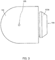
- FIG. 3 is a side view illustrating an example of socket section 103 according to the present embodiment. The side view in FIG. 3 is a view of socket section 103 as viewed from the direction of dotted arrow in FIG. 2 .
- Socket section 103 is an elastic body having an L shape, and ultraviolet lamp 100 is fitted in recessed part 103a at one end, and protruding part 103b at the other end is fitted in the opening of inner box 4. Accordingly, ultraviolet lamp 100 is supported by socket section 103, and socket section 103 is fixed to a casing (hereinafter referred to simply as casing) composed of outer box 2, inner box 4, and insulation material 6.
- Socket section 103 is provided with, as shown in FIGS. 2 and 3 , first opening 105 which is opened toward an interior of the casing (the interior of inner box 4) and second opening 106 in fluid communication with first opening 105 and through which electric wire 101 passes.
- the casing is provided with third opening 107 for guiding electric wire 101 to the outside and in fluid communication with second opening 106.
- First opening 105, second opening 106, and third opening 107 form an exhaust passage for exhausting the gas inside the casing to the outside.
- Evaporation member 104 is a member having one end disposed in first opening 105 and the other end disposed at the exterior of the casing, and causing water absorbed to evaporate from the one end from the other end.
- Evaporation member 104 may be made of paper, cloth or the like, and may be made of an inorganic or organic material as long as it causes capillary action to water.
- Evaporation member 104 is disposed utilizing a gap between part 6a of the insulation material and the other part.
- evaporation member 104 has air permeability, even if evaporation member 104 is disposed in first opening 105 and second opening 106 as shown in FIG. 2 , exhaust of gas through the above-described exhaust route is not hindered.
- Second opening 106 and third opening 107 are essentially required openings to pass electric wire 101.
- exhaust passages can be formed only by forming first opening 105 in socket section 103.
- the number of parts does not increase to form the exhaust passage. Also, since there is no need to add an exhaust pipe to form the exhaust passage, the installation space for installing the exhaust pipe is also unnecessary. Furthermore, the exhaust passage can be easily formed.
- first opening 105 water accumulated in first opening 105, second opening 106, and third opening 107 can be removed.
- the water can be absorbed and removed by evaporation member 104, leaving the water to evaporate outside the casing. As a result, it is possible to suppress the reproduction of various bacteria.
- one end of evaporation member 104 is disposed in first opening 105 and other end is disposed at the exterior of the casing.
- one end of evaporation member 104 is disposed in second opening 106, and the other end may be disposed at the exterior of the casing.
- heating section 108 may be provided to evaporate the water.
- FIG. 4 illustrates an example of heating section 108 provided on an electric wire passing through the exhaust passage of the culture apparatus according to the present embodiment.
- FIG. 4 illustrates heating section 108 tied to electric wire 101 using binding band 109.
- Heating section 108 is a heater that generates heat.
- heating section 108 is a heater that generates heat by means of current flowing through the resistor.
- heating section 108 is provided at the exterior of the casing. Also, heating section 108 is provided to contact electric wire 101 over a predetermined range.
- Heating section 108 is in contact with electric wire 101 over a predetermined range, and heating section 108 heats electric wire 101. This heat is transmitted to socket section 103 and part 6a of the insulation material, and socket section 103 and part 6a of the insulation material are heated.
- first opening 105 and second opening 106 of socket section 103 can be evaporated. Also, water accumulated in third opening 107 of part 6a of the insulation material can be evaporated.
- Heating section 108 may be provided together with evaporation member 104.
- culture apparatus 1 for culturing the cultures housed in the casing and sterilization by irradiation with ultraviolet light has been described.
- the present invention is not limited to such culture apparatus 1, and may be applied to a storage device that stores an object in a casing.
- a housing apparatus according to the present invention is suitable for use in a housing apparatus that performs sterilization by irradiation with ultraviolet light.
Landscapes
- Health & Medical Sciences (AREA)
- Life Sciences & Earth Sciences (AREA)
- Chemical & Material Sciences (AREA)
- Zoology (AREA)
- Wood Science & Technology (AREA)
- Organic Chemistry (AREA)
- Engineering & Computer Science (AREA)
- Bioinformatics & Cheminformatics (AREA)
- General Health & Medical Sciences (AREA)
- Biochemistry (AREA)
- General Engineering & Computer Science (AREA)
- Microbiology (AREA)
- Sustainable Development (AREA)
- Biomedical Technology (AREA)
- Biotechnology (AREA)
- Genetics & Genomics (AREA)
- Animal Behavior & Ethology (AREA)
- Veterinary Medicine (AREA)
- Epidemiology (AREA)
- Public Health (AREA)
- Molecular Biology (AREA)
- Physics & Mathematics (AREA)
- Thermal Sciences (AREA)
- Analytical Chemistry (AREA)
- Apparatus Associated With Microorganisms And Enzymes (AREA)
- Physical Water Treatments (AREA)
- Disinfection, Sterilisation Or Deodorisation Of Air (AREA)
- Apparatus For Disinfection Or Sterilisation (AREA)
Abstract
Description
- The present invention relates to a housing apparatus that performs sterilization by irradiation with ultraviolet light.
- In the related art, culture apparatuses for culturing cultures such as cells or microorganisms are widely used. Some culture apparatuses are provided with a heater or the like to adjust the temperature in the culture chamber. In addition, some apparatuses are provided with ultraviolet lamps to sterilize the culture chamber.
- Patent Literature (hereinafter, abbreviated as PTL) 1 discloses a culture apparatus provided with an exhaust pipe for ventilating the culture chamber. In this culture apparatus, it is possible to prevent a gas generated by cell metabolism from accumulating in the culture chamber.
- PTL 1
Japanese Patent Application Laid-Open No.H08-322552 - However, since an exhaust pipe is added, the related art of PTL 1 described above has an increased number of parts and requires a space for providing the exhaust pipe in the culture apparatus.
- In addition, when additionally providing an ultraviolet lamp in the culture apparatus, it is necessary to form an opening for passing the electric wire for supplying power to the ultraviolet lamp in addition to the opening for passing the exhaust pipe in the casing of the culture apparatus, so that the working is laborious.
- An object of the present invention is to provide a housing apparatus that can easily form an exhaust passage for exhausting the gas in the casing, without increasing the number of parts and eliminate the need for a large installation space.
- A housing apparatus of the present invention is a housing apparatus that performs sterilization by irradiation with ultraviolet light, the housing apparatus including: an ultraviolet lamp that radiates the ultraviolet light; an electric wire that supplies power to the ultraviolet lamp; a socket section that supports the ultraviolet lamp; and a casing inside of which the ultraviolet lamp is disposed, in which the socket section includes a first opening and a second opening, the first opening being opened toward an interior of the casing, the second opening being in fluid communication with the first opening and being an opening through which the electric wire passes, and in the casing, a third opening which guides the electric wire to outside is formed, the third opening being in fluid communication with the second opening.
- According to the present invention, it is possible to easily form an exhaust passage for exhausting the gas in the casing without increasing the number of parts and eliminate the need for a large installation space.
-
-
FIG. 1 is a cross-sectional side view illustrating an example of an overall structure of a culture apparatus according to the present embodiment. -
FIG. 2 is a cross-sectional plan view illustrating an example of an exhaust passage of the culture apparatus according to the present embodiment. -
FIG. 3 is a side view illustrating an example of a socket section according to the present embodiment. -
FIG. 4 illustrates an example of a heating section provided in an electric wire which passes the exhaust passage of the culture apparatus which concerns on the present embodiment. - Hereinafter, embodiments of the present invention will be described in detail with reference to the drawings.
- First, an example of the overall structure of culture apparatus 1 according to the present embodiment will be described.
FIG. 1 is a cross-sectional side view illustrating an example of an overall structure of culture apparatus 1 according to the present embodiment. - As illustrated in
FIG. 1 , culture apparatus 1 includesinner box 4,outer box 2, inner door 4a,outer door 3, andultraviolet lamp 100. The structure aroundultraviolet lamp 100 will be described with reference toFIG. 2 in detail later. Culture apparatus 1 is for culturing cultures such as cells and microorganisms in culture chamber 4b ofinner box 4. -
Inner box 4 is, for example, a substantially rectangular box made of stainless steel, and culture chamber 4b is formed inside thereof. Culture chamber 4b is partitioned in a vertical direction (Z-axis direction) by a plurality ofshelves 42 for placing the cultures. - Shelves 42 include a plurality of holes (not illustrated) penetrating therethrough in a vertical direction, and are supported by a pair of
shelf holders 41 provided in an interior of the two inner surfaces perpendicular to X-axis ofinner box 4.Shelves 42 andshelf holders 41 are made, for example, of stainless steel. -
Outer box 2 is, for example, a box made of stainless steel having a substantially similar shape toinner boxes 4, and housesinner boxes 4 in the interior thereof in a state of being insulated from the outside air. Provided betweenouter box 2 andinner boxes 4 isinsulation material 6 for heat retention.Outer box 2,inner box 4, andinsulation material 6 are casings of culture apparatus 1 the inside of whichultraviolet lamp 100 is disposed. - On an outer surface on a back side (negative direction side of Y-axis) of
outer box 2, there are provided a sensor (not illustrated) for detecting a temperature in culture chamber 4b, a nozzle (not illustrated) for injecting gas such as carbon dioxide into culture chamber 4b, a sensor (not illustrated) for detecting a concentration of carbon dioxide in the interior of culture chamber 4b, andsensor box 7 having a heater (not illustrated) or the like. - The nozzle, the sensor or the like are, for example, attached to
outer box 2 from the outer surface thereof on the back side ofinner box 4 through a hole (not illustrated) formed on the outer surface on the back side ofouter box 2. The outer surface ofouter box 2 on the back side andsensor box 7 are covered withcover 21 having an insulation material (not illustrated) on an inner side thereof. - Inner door 4a is a flat-panel shaped door that enables opening and closing of the opening on the front side of inner box 4 (the positive direction side of Y-axis). Inner door 4a is, for example, formed of reinforce glass. When inner door 4a is closed, the interior of
inner box 4 may be hermetically sealed by using a packing (not illustrated). -
Outer door 3 is a door having a flat-panel shape that enables opening and closing of the opening ofouter box 2 on the front side.Outer door 3 is formed, for example, of metal.Outer door 3 includes inside thereofdoor body 31 formed of a metal and provided on an inner side thereof with an insulation material (not illustrated) for heat retention and a heater (not illustrated) or the like, for adjusting the temperature in the interior of culture chamber 4b, and packing 33 attached to protrudingpart 31a opposingouter box 2. -
Outer door 3 further includescontrol panel 32 on the front side ofdoor body 31.Control panel 32 has components such as a keyboard (not illustrated) for inputting lighting duration ofultraviolet lamp 100 or the like, and a display (not illustrated) for displaying various information. -
Ultraviolet lamp 100 kills bacteria contained in the air passing under duct 43 (the negative direction side of Z-axis) and the humidified water inhumidification tray 44 arranged below duct 43, and is placed at a position where ultraviolet light can be radiated. - Here, duct 43 is composed of the back side wall of
inner box 4 andwall plate 5 to form an air flow path therebetween. For example,wall plate 5 is made of stainless steel. Further,fan 5a (sirocco fan) is provided on the upper side (the positive direction side of Z-axis) in duct 43. -
Humidification tray 44 is covered withcover 45 havinghole 45a on the front side. For example,cover 45 is made of stainless steel. - Also, with
fan 5a being rotated in a fixed direction, the air on the side ofshelves 42 above culture chamber 4b flows into duct 43 throughinlet port 51a as shown by the arrow, flows in duct 43 from the top to the bottom, and then flows forward on the surface of the humidified water. There, the humidified air passes throughholes 45a ofcover 45 to form an ascending air flow. - The air which has risen to the upper side of culture chamber 4b again flows into duct 43 through
inlet port 51a. By such air circulation, inside culture chamber 4b is maintained at a substantially uniform temperature, humidity, and gas concentration such as carbon dioxide. - Further,
ultraviolet lamp 100 is provided with an optical filter or the like to suppress generation of ultraviolet light having a wavelength of 200 nm or less. As a result, the generation of ozone from the gas in duct 43 (air, gas such as carbon dioxide, water vapor, and the like) is suppressed. In addition, the adverse effect of ozone on the culture in culture chamber 4b is also suppressed. - Next, an example of exhaust passage of the culture apparatus according to the present embodiment will be described.
FIG. 2 is a cross-sectional plan view showing an example of exhaust passage of the culture apparatus according to the present embodiment. - As shown in
FIG. 2 , culture apparatus 1 includeselectric wire 101,connector 102,socket section 103, andevaporation member 104 aroundultraviolet lamp 100. -
Electric wire 101 supplies power toultraviolet lamp 100. Althoughelectric wire 101 is drawn short inFIG. 2 , the length ofelectric wire 101 may be longer. Also,FIG. 2 illustrates that oneelectric wire 101 is connected to each end ofultraviolet lamp 100, but two or moreelectric wires 101 may be connected to each end ofultraviolet lamp 100.Connector 102 is a component for connectingelectric wire 101 to an electric circuit board (not illustrated). -
Socket section 103 is a component that supportsultraviolet lamp 100.FIG. 3 is a side view illustrating an example ofsocket section 103 according to the present embodiment. The side view inFIG. 3 is a view ofsocket section 103 as viewed from the direction of dotted arrow inFIG. 2 . -
Socket section 103 is an elastic body having an L shape, andultraviolet lamp 100 is fitted in recessedpart 103a at one end, and protrudingpart 103b at the other end is fitted in the opening ofinner box 4. Accordingly,ultraviolet lamp 100 is supported bysocket section 103, andsocket section 103 is fixed to a casing (hereinafter referred to simply as casing) composed ofouter box 2,inner box 4, andinsulation material 6. -
Socket section 103 is provided with, as shown inFIGS. 2 and3 ,first opening 105 which is opened toward an interior of the casing (the interior of inner box 4) andsecond opening 106 in fluid communication withfirst opening 105 and through whichelectric wire 101 passes. - The casing is provided with
third opening 107 for guidingelectric wire 101 to the outside and in fluid communication withsecond opening 106.First opening 105,second opening 106, andthird opening 107 form an exhaust passage for exhausting the gas inside the casing to the outside. - That is, when the pressure of the gas inside the casing is higher than the pressure of the gas outside the casing, the gas inside the casing is exhausted to the outside via
first opening 105,second opening 106, andthird opening 107. -
Evaporation member 104 is a member having one end disposed infirst opening 105 and the other end disposed at the exterior of the casing, and causing water absorbed to evaporate from the one end from the other end.Evaporation member 104 may be made of paper, cloth or the like, and may be made of an inorganic or organic material as long as it causes capillary action to water. - Here, when replacing
ultraviolet lamp 100,part 6a of the insulation material is removed for easy replacement.Evaporation member 104 is disposed utilizing a gap betweenpart 6a of the insulation material and the other part. In addition, sinceevaporation member 104 has air permeability, even ifevaporation member 104 is disposed infirst opening 105 andsecond opening 106 as shown inFIG. 2 , exhaust of gas through the above-described exhaust route is not hindered. -
Second opening 106 andthird opening 107 are essentially required openings to passelectric wire 101. In the present embodiment, by utilizing these openings, exhaust passages can be formed only by formingfirst opening 105 insocket section 103. - Therefore, the number of parts does not increase to form the exhaust passage. Also, since there is no need to add an exhaust pipe to form the exhaust passage, the installation space for installing the exhaust pipe is also unnecessary. Furthermore, the exhaust passage can be easily formed.
- Further, by providing
evaporation member 104 described above, water accumulated infirst opening 105,second opening 106, andthird opening 107 can be removed. For example, even if the condensation is generated insocket section 103 by contact with the outside air, the water can be absorbed and removed byevaporation member 104, leaving the water to evaporate outside the casing. As a result, it is possible to suppress the reproduction of various bacteria. - In the above embodiment, one end of
evaporation member 104 is disposed infirst opening 105 and other end is disposed at the exterior of the casing. However, one end ofevaporation member 104 is disposed insecond opening 106, and the other end may be disposed at the exterior of the casing. - Also, instead of
evaporation member 104,heating section 108 may be provided to evaporate the water.FIG. 4 illustrates an example ofheating section 108 provided on an electric wire passing through the exhaust passage of the culture apparatus according to the present embodiment.FIG. 4 illustratesheating section 108 tied toelectric wire 101 usingbinding band 109. -
Heating section 108 is a heater that generates heat. For example,heating section 108 is a heater that generates heat by means of current flowing through the resistor. Also,heating section 108 is provided at the exterior of the casing. Also,heating section 108 is provided to contactelectric wire 101 over a predetermined range. -
Heating section 108 is in contact withelectric wire 101 over a predetermined range, andheating section 108 heatselectric wire 101. This heat is transmitted tosocket section 103 andpart 6a of the insulation material, andsocket section 103 andpart 6a of the insulation material are heated. - Therefore, the water accumulated in
first opening 105 andsecond opening 106 ofsocket section 103 can be evaporated. Also, water accumulated inthird opening 107 ofpart 6a of the insulation material can be evaporated.Heating section 108 may be provided together withevaporation member 104. - In the above embodiment, culture apparatus 1 for culturing the cultures housed in the casing and sterilization by irradiation with ultraviolet light has been described. However, the present invention is not limited to such culture apparatus 1, and may be applied to a storage device that stores an object in a casing.
- The disclosures of the specification, drawings and abstract included in Japanese Patent Application No.
2017-009724 filed on January 23, 2017 2017-108074 filed on May 31, 2017 - A housing apparatus according to the present invention is suitable for use in a housing apparatus that performs sterilization by irradiation with ultraviolet light.
-
- 1 Culture apparatus
- 2 Outer box
- 3 Outer door
- 4 Inner box
- 4a Inner door
- 4b Culture chamber
- 5 Wall plate
- 5a Fan
- 6 Insulation material
- 7 Sensor box
- 21 Cover
- 31 Door body
- 31a Protruding part
- 32 Control panel
- 33 Packing
- 41 Shelf holder
- 42 Shelf
- 43 Duct
- 44 Humidification tray
- 45 Cover
- 45a Hole
- 51a Inlet port
- 100 Ultraviolet lamp
- 101 Electric wire
- 102 Connector
- 103 Socket section
- 103a Recessed part
- 103b Protruding part
- 104 Evaporation member
- 105 First opening
- 106 Second opening
- 107 Third opening
- 108 Heating section
- 109 Binding band
Claims (3)
- A housing apparatus that performs sterilization by irradiation with ultraviolet light, the housing apparatus comprising:an ultraviolet lamp that radiates the ultraviolet light;an electric wire that supplies power to the ultraviolet lamp;a socket section that supports the ultraviolet lamp; anda casing inside of which the ultraviolet lamp is disposed, whereinthe socket section includes a first opening and a second opening, the first opening being opened toward an interior of the casing, the second opening being in fluid communication with the first opening and being an opening through which the electric wire passes, andin the casing, a third opening which guides the electric wire to outside is formed, the third opening being in fluid communication with the second opening.
- The housing apparatus according to claim 1, further comprising an evaporation member including one end disposed in the first opening or the second opening and another end disposed at an exterior of the casing, the evaporation member causing water absorbed from the one end to evaporate from the other end.
- The housing apparatus according to claim 1 or 2, further comprising a heating section at the exterior of the casing, the heating section being configured to heat the electric wire.
Applications Claiming Priority (3)
| Application Number | Priority Date | Filing Date | Title |
|---|---|---|---|
| JP2017009724 | 2017-01-23 | ||
| JP2017108074 | 2017-05-31 | ||
| PCT/JP2018/000069 WO2018135311A1 (en) | 2017-01-23 | 2018-01-05 | Accommodation device |
Publications (3)
| Publication Number | Publication Date |
|---|---|
| EP3561039A1 true EP3561039A1 (en) | 2019-10-30 |
| EP3561039A4 EP3561039A4 (en) | 2020-01-22 |
| EP3561039B1 EP3561039B1 (en) | 2021-03-03 |
Family
ID=62907861
Family Applications (1)
| Application Number | Title | Priority Date | Filing Date |
|---|---|---|---|
| EP18741462.8A Active EP3561039B1 (en) | 2017-01-23 | 2018-01-05 | Accommodation device |
Country Status (5)
| Country | Link |
|---|---|
| US (1) | US10918755B2 (en) |
| EP (1) | EP3561039B1 (en) |
| JP (1) | JP6784779B2 (en) |
| CN (1) | CN110214175B (en) |
| WO (1) | WO2018135311A1 (en) |
Families Citing this family (4)
| Publication number | Priority date | Publication date | Assignee | Title |
|---|---|---|---|---|
| EP3825395B1 (en) * | 2018-09-06 | 2022-07-06 | PHC Corporation | Culture device |
| CN114729293B (en) * | 2019-09-04 | 2023-09-22 | 埃姆布里恩特股份有限公司 | Incubator with air curtain |
| EP4281120A4 (en) * | 2021-01-21 | 2024-11-20 | Lions World Vision Institute, Inc. | Ultraviolet light delivery apparatus |
| EP4353812A4 (en) * | 2021-07-15 | 2025-03-05 | PHC Holdings Corporation | CULTURE APPARATUS |
Family Cites Families (24)
| Publication number | Priority date | Publication date | Assignee | Title |
|---|---|---|---|---|
| JPS5942882A (en) * | 1982-09-03 | 1984-03-09 | Sanyo Electric Co Ltd | Thermo-hygrostatic apparatus |
| JPH04169774A (en) * | 1990-11-02 | 1992-06-17 | Sanyo Electric Co Ltd | Low temperature chamber |
| US5290439A (en) * | 1992-06-12 | 1994-03-01 | Claus Buchwald | Device for purifying a flow of liquid by means of ultraviolet radiation |
| CN1069453C (en) * | 1995-02-22 | 2001-08-08 | 松下电工株式会社 | lamp holder |
| JP3143360B2 (en) | 1995-05-26 | 2001-03-07 | 三洋電機株式会社 | Ventilation equipment for the culture room |
| JPH09306203A (en) * | 1996-05-10 | 1997-11-28 | Koito Mfg Co Ltd | Socket for discharge lamp bulb |
| US6325668B1 (en) * | 1996-07-12 | 2001-12-04 | Hirose Electric Co., Ltd. | Lamp socket |
| US6224428B1 (en) * | 1997-04-09 | 2001-05-01 | The Whitaker Corporation | Electrical connector and method of assembling and connecting the same with circuit devices |
| JP2001143839A (en) * | 1999-11-17 | 2001-05-25 | Hirose Electric Co Ltd | Lamp socket |
| US7052301B2 (en) * | 2003-06-17 | 2006-05-30 | Christiana Industries, Inc. | Lamp socket |
| JP2005118021A (en) * | 2003-10-20 | 2005-05-12 | Sanyo Electric Co Ltd | Incubator |
| US7287875B2 (en) * | 2005-03-02 | 2007-10-30 | Matsushita Seika | Air-filled flashing light decorator |
| JP5195750B2 (en) * | 2007-04-25 | 2013-05-15 | 株式会社Gsユアサ | Light source device |
| JP5134875B2 (en) * | 2007-07-06 | 2013-01-30 | 日本たばこ産業株式会社 | Cigarette storage device |
| JP5341434B2 (en) * | 2008-08-26 | 2013-11-13 | パナソニックヘルスケア株式会社 | Incubator |
| EP2319911B1 (en) * | 2008-08-26 | 2019-04-24 | PHC Holdings Corporation | Culture apparatus |
| JP5011488B2 (en) | 2008-08-27 | 2012-08-29 | パナソニックヘルスケア株式会社 | Incubator |
| JP4764961B2 (en) * | 2009-12-22 | 2011-09-07 | パナソニック株式会社 | Light bulb shaped lamp |
| JP5789164B2 (en) * | 2011-09-30 | 2015-10-07 | 株式会社アイ・ライティング・システム | Lighting device |
| US20130322087A1 (en) * | 2012-05-29 | 2013-12-05 | Wei-Jen Tseng | Waterproof fairy light |
| CN204240133U (en) * | 2014-12-11 | 2015-04-01 | 吴庆州 | A kind of high-efficiency and energy-saving type LED |
| JP6528555B2 (en) | 2015-06-19 | 2019-06-12 | 富士ゼロックス株式会社 | Developing device and image forming apparatus |
| US10816165B2 (en) * | 2015-11-19 | 2020-10-27 | Lsi Industries, Inc. | LED luminaire assembly |
| JP6617546B2 (en) | 2015-12-11 | 2019-12-11 | 富士電機株式会社 | Semiconductor device and manufacturing method of semiconductor device |
-
2018
- 2018-01-05 JP JP2018563267A patent/JP6784779B2/en active Active
- 2018-01-05 EP EP18741462.8A patent/EP3561039B1/en active Active
- 2018-01-05 WO PCT/JP2018/000069 patent/WO2018135311A1/en not_active Ceased
- 2018-01-05 CN CN201880007427.0A patent/CN110214175B/en active Active
-
2019
- 2019-07-22 US US16/518,778 patent/US10918755B2/en active Active
Also Published As
| Publication number | Publication date |
|---|---|
| EP3561039A4 (en) | 2020-01-22 |
| CN110214175A (en) | 2019-09-06 |
| US10918755B2 (en) | 2021-02-16 |
| US20190336634A1 (en) | 2019-11-07 |
| JP6784779B2 (en) | 2020-11-11 |
| JPWO2018135311A1 (en) | 2019-11-07 |
| WO2018135311A1 (en) | 2018-07-26 |
| CN110214175B (en) | 2022-06-14 |
| EP3561039B1 (en) | 2021-03-03 |
Similar Documents
| Publication | Publication Date | Title |
|---|---|---|
| US10918755B2 (en) | Housing apparatus | |
| KR102374984B1 (en) | incubator | |
| US8815579B2 (en) | Culture apparatus provided with heat pipe | |
| EP2963106B1 (en) | Culture apparatus | |
| US9464266B2 (en) | Sensor unit and constant-temperature device | |
| JPWO2017169850A1 (en) | CULTURE DEVICE AND CULTURE DEVICE CONTROL METHOD | |
| WO2010024163A1 (en) | Culture apparatus | |
| US20210284949A1 (en) | Culture device | |
| JP6666768B2 (en) | Culture device | |
| US12297419B2 (en) | Culture device | |
| JP6753680B2 (en) | Incubator | |
| JP5624711B2 (en) | Incubator | |
| US12180455B2 (en) | Culture device | |
| US20240417666A1 (en) | Culturing apparatus and culture system | |
| WO2023286461A1 (en) | Led module and culture apparatus | |
| JP2025012331A (en) | Culture Equipment | |
| WO2023286460A1 (en) | Culture apparatus | |
| JP6142443B2 (en) | CULTURE SYSTEM AND METHOD OF USING CULTURE SYSTEM |
Legal Events
| Date | Code | Title | Description |
|---|---|---|---|
| STAA | Information on the status of an ep patent application or granted ep patent |
Free format text: STATUS: THE INTERNATIONAL PUBLICATION HAS BEEN MADE |
|
| PUAI | Public reference made under article 153(3) epc to a published international application that has entered the european phase |
Free format text: ORIGINAL CODE: 0009012 |
|
| STAA | Information on the status of an ep patent application or granted ep patent |
Free format text: STATUS: REQUEST FOR EXAMINATION WAS MADE |
|
| 17P | Request for examination filed |
Effective date: 20190722 |
|
| AK | Designated contracting states |
Kind code of ref document: A1 Designated state(s): AL AT BE BG CH CY CZ DE DK EE ES FI FR GB GR HR HU IE IS IT LI LT LU LV MC MK MT NL NO PL PT RO RS SE SI SK SM TR |
|
| AX | Request for extension of the european patent |
Extension state: BA ME |
|
| A4 | Supplementary search report drawn up and despatched |
Effective date: 20200103 |
|
| RIC1 | Information provided on ipc code assigned before grant |
Ipc: C12M 1/00 20060101AFI20191218BHEP Ipc: C12M 1/12 20060101ALI20191218BHEP |
|
| DAV | Request for validation of the european patent (deleted) | ||
| DAX | Request for extension of the european patent (deleted) | ||
| GRAP | Despatch of communication of intention to grant a patent |
Free format text: ORIGINAL CODE: EPIDOSNIGR1 |
|
| STAA | Information on the status of an ep patent application or granted ep patent |
Free format text: STATUS: GRANT OF PATENT IS INTENDED |
|
| INTG | Intention to grant announced |
Effective date: 20201015 |
|
| GRAS | Grant fee paid |
Free format text: ORIGINAL CODE: EPIDOSNIGR3 |
|
| GRAA | (expected) grant |
Free format text: ORIGINAL CODE: 0009210 |
|
| STAA | Information on the status of an ep patent application or granted ep patent |
Free format text: STATUS: THE PATENT HAS BEEN GRANTED |
|
| AK | Designated contracting states |
Kind code of ref document: B1 Designated state(s): AL AT BE BG CH CY CZ DE DK EE ES FI FR GB GR HR HU IE IS IT LI LT LU LV MC MK MT NL NO PL PT RO RS SE SI SK SM TR |
|
| REG | Reference to a national code |
Ref country code: GB Ref legal event code: FG4D |
|
| REG | Reference to a national code |
Ref country code: CH Ref legal event code: EP Ref country code: AT Ref legal event code: REF Ref document number: 1367219 Country of ref document: AT Kind code of ref document: T Effective date: 20210315 |
|
| REG | Reference to a national code |
Ref country code: DE Ref legal event code: R096 Ref document number: 602018013474 Country of ref document: DE |
|
| REG | Reference to a national code |
Ref country code: NL Ref legal event code: FP Ref country code: IE Ref legal event code: FG4D |
|
| REG | Reference to a national code |
Ref country code: LT Ref legal event code: MG9D |
|
| PG25 | Lapsed in a contracting state [announced via postgrant information from national office to epo] |
Ref country code: LT Free format text: LAPSE BECAUSE OF FAILURE TO SUBMIT A TRANSLATION OF THE DESCRIPTION OR TO PAY THE FEE WITHIN THE PRESCRIBED TIME-LIMIT Effective date: 20210303 Ref country code: NO Free format text: LAPSE BECAUSE OF FAILURE TO SUBMIT A TRANSLATION OF THE DESCRIPTION OR TO PAY THE FEE WITHIN THE PRESCRIBED TIME-LIMIT Effective date: 20210603 Ref country code: GR Free format text: LAPSE BECAUSE OF FAILURE TO SUBMIT A TRANSLATION OF THE DESCRIPTION OR TO PAY THE FEE WITHIN THE PRESCRIBED TIME-LIMIT Effective date: 20210604 Ref country code: FI Free format text: LAPSE BECAUSE OF FAILURE TO SUBMIT A TRANSLATION OF THE DESCRIPTION OR TO PAY THE FEE WITHIN THE PRESCRIBED TIME-LIMIT Effective date: 20210303 Ref country code: HR Free format text: LAPSE BECAUSE OF FAILURE TO SUBMIT A TRANSLATION OF THE DESCRIPTION OR TO PAY THE FEE WITHIN THE PRESCRIBED TIME-LIMIT Effective date: 20210303 Ref country code: BG Free format text: LAPSE BECAUSE OF FAILURE TO SUBMIT A TRANSLATION OF THE DESCRIPTION OR TO PAY THE FEE WITHIN THE PRESCRIBED TIME-LIMIT Effective date: 20210603 |
|
| REG | Reference to a national code |
Ref country code: AT Ref legal event code: MK05 Ref document number: 1367219 Country of ref document: AT Kind code of ref document: T Effective date: 20210303 |
|
| PG25 | Lapsed in a contracting state [announced via postgrant information from national office to epo] |
Ref country code: SE Free format text: LAPSE BECAUSE OF FAILURE TO SUBMIT A TRANSLATION OF THE DESCRIPTION OR TO PAY THE FEE WITHIN THE PRESCRIBED TIME-LIMIT Effective date: 20210303 Ref country code: RS Free format text: LAPSE BECAUSE OF FAILURE TO SUBMIT A TRANSLATION OF THE DESCRIPTION OR TO PAY THE FEE WITHIN THE PRESCRIBED TIME-LIMIT Effective date: 20210303 Ref country code: PL Free format text: LAPSE BECAUSE OF FAILURE TO SUBMIT A TRANSLATION OF THE DESCRIPTION OR TO PAY THE FEE WITHIN THE PRESCRIBED TIME-LIMIT Effective date: 20210303 Ref country code: LV Free format text: LAPSE BECAUSE OF FAILURE TO SUBMIT A TRANSLATION OF THE DESCRIPTION OR TO PAY THE FEE WITHIN THE PRESCRIBED TIME-LIMIT Effective date: 20210303 |
|
| PG25 | Lapsed in a contracting state [announced via postgrant information from national office to epo] |
Ref country code: AT Free format text: LAPSE BECAUSE OF FAILURE TO SUBMIT A TRANSLATION OF THE DESCRIPTION OR TO PAY THE FEE WITHIN THE PRESCRIBED TIME-LIMIT Effective date: 20210303 Ref country code: SM Free format text: LAPSE BECAUSE OF FAILURE TO SUBMIT A TRANSLATION OF THE DESCRIPTION OR TO PAY THE FEE WITHIN THE PRESCRIBED TIME-LIMIT Effective date: 20210303 Ref country code: EE Free format text: LAPSE BECAUSE OF FAILURE TO SUBMIT A TRANSLATION OF THE DESCRIPTION OR TO PAY THE FEE WITHIN THE PRESCRIBED TIME-LIMIT Effective date: 20210303 Ref country code: CZ Free format text: LAPSE BECAUSE OF FAILURE TO SUBMIT A TRANSLATION OF THE DESCRIPTION OR TO PAY THE FEE WITHIN THE PRESCRIBED TIME-LIMIT Effective date: 20210303 |
|
| PG25 | Lapsed in a contracting state [announced via postgrant information from national office to epo] |
Ref country code: SK Free format text: LAPSE BECAUSE OF FAILURE TO SUBMIT A TRANSLATION OF THE DESCRIPTION OR TO PAY THE FEE WITHIN THE PRESCRIBED TIME-LIMIT Effective date: 20210303 Ref country code: PT Free format text: LAPSE BECAUSE OF FAILURE TO SUBMIT A TRANSLATION OF THE DESCRIPTION OR TO PAY THE FEE WITHIN THE PRESCRIBED TIME-LIMIT Effective date: 20210705 Ref country code: RO Free format text: LAPSE BECAUSE OF FAILURE TO SUBMIT A TRANSLATION OF THE DESCRIPTION OR TO PAY THE FEE WITHIN THE PRESCRIBED TIME-LIMIT Effective date: 20210303 Ref country code: IS Free format text: LAPSE BECAUSE OF FAILURE TO SUBMIT A TRANSLATION OF THE DESCRIPTION OR TO PAY THE FEE WITHIN THE PRESCRIBED TIME-LIMIT Effective date: 20210703 |
|
| REG | Reference to a national code |
Ref country code: DE Ref legal event code: R097 Ref document number: 602018013474 Country of ref document: DE |
|
| PLBE | No opposition filed within time limit |
Free format text: ORIGINAL CODE: 0009261 |
|
| STAA | Information on the status of an ep patent application or granted ep patent |
Free format text: STATUS: NO OPPOSITION FILED WITHIN TIME LIMIT |
|
| PG25 | Lapsed in a contracting state [announced via postgrant information from national office to epo] |
Ref country code: DK Free format text: LAPSE BECAUSE OF FAILURE TO SUBMIT A TRANSLATION OF THE DESCRIPTION OR TO PAY THE FEE WITHIN THE PRESCRIBED TIME-LIMIT Effective date: 20210303 Ref country code: AL Free format text: LAPSE BECAUSE OF FAILURE TO SUBMIT A TRANSLATION OF THE DESCRIPTION OR TO PAY THE FEE WITHIN THE PRESCRIBED TIME-LIMIT Effective date: 20210303 Ref country code: ES Free format text: LAPSE BECAUSE OF FAILURE TO SUBMIT A TRANSLATION OF THE DESCRIPTION OR TO PAY THE FEE WITHIN THE PRESCRIBED TIME-LIMIT Effective date: 20210303 |
|
| 26N | No opposition filed |
Effective date: 20211206 |
|
| PG25 | Lapsed in a contracting state [announced via postgrant information from national office to epo] |
Ref country code: SI Free format text: LAPSE BECAUSE OF FAILURE TO SUBMIT A TRANSLATION OF THE DESCRIPTION OR TO PAY THE FEE WITHIN THE PRESCRIBED TIME-LIMIT Effective date: 20210303 |
|
| PG25 | Lapsed in a contracting state [announced via postgrant information from national office to epo] |
Ref country code: IT Free format text: LAPSE BECAUSE OF FAILURE TO SUBMIT A TRANSLATION OF THE DESCRIPTION OR TO PAY THE FEE WITHIN THE PRESCRIBED TIME-LIMIT Effective date: 20210303 |
|
| PG25 | Lapsed in a contracting state [announced via postgrant information from national office to epo] |
Ref country code: IS Free format text: LAPSE BECAUSE OF FAILURE TO SUBMIT A TRANSLATION OF THE DESCRIPTION OR TO PAY THE FEE WITHIN THE PRESCRIBED TIME-LIMIT Effective date: 20210703 |
|
| PG25 | Lapsed in a contracting state [announced via postgrant information from national office to epo] |
Ref country code: MC Free format text: LAPSE BECAUSE OF FAILURE TO SUBMIT A TRANSLATION OF THE DESCRIPTION OR TO PAY THE FEE WITHIN THE PRESCRIBED TIME-LIMIT Effective date: 20210303 |
|
| REG | Reference to a national code |
Ref country code: CH Ref legal event code: PL |
|
| REG | Reference to a national code |
Ref country code: BE Ref legal event code: MM Effective date: 20220131 |
|
| PG25 | Lapsed in a contracting state [announced via postgrant information from national office to epo] |
Ref country code: LU Free format text: LAPSE BECAUSE OF NON-PAYMENT OF DUE FEES Effective date: 20220105 |
|
| PG25 | Lapsed in a contracting state [announced via postgrant information from national office to epo] |
Ref country code: BE Free format text: LAPSE BECAUSE OF NON-PAYMENT OF DUE FEES Effective date: 20220131 |
|
| PG25 | Lapsed in a contracting state [announced via postgrant information from national office to epo] |
Ref country code: LI Free format text: LAPSE BECAUSE OF NON-PAYMENT OF DUE FEES Effective date: 20220131 Ref country code: CH Free format text: LAPSE BECAUSE OF NON-PAYMENT OF DUE FEES Effective date: 20220131 |
|
| PG25 | Lapsed in a contracting state [announced via postgrant information from national office to epo] |
Ref country code: IE Free format text: LAPSE BECAUSE OF NON-PAYMENT OF DUE FEES Effective date: 20220105 |
|
| PG25 | Lapsed in a contracting state [announced via postgrant information from national office to epo] |
Ref country code: MK Free format text: LAPSE BECAUSE OF FAILURE TO SUBMIT A TRANSLATION OF THE DESCRIPTION OR TO PAY THE FEE WITHIN THE PRESCRIBED TIME-LIMIT Effective date: 20210303 Ref country code: CY Free format text: LAPSE BECAUSE OF FAILURE TO SUBMIT A TRANSLATION OF THE DESCRIPTION OR TO PAY THE FEE WITHIN THE PRESCRIBED TIME-LIMIT Effective date: 20210303 |
|
| PG25 | Lapsed in a contracting state [announced via postgrant information from national office to epo] |
Ref country code: HU Free format text: LAPSE BECAUSE OF FAILURE TO SUBMIT A TRANSLATION OF THE DESCRIPTION OR TO PAY THE FEE WITHIN THE PRESCRIBED TIME-LIMIT; INVALID AB INITIO Effective date: 20180105 |
|
| PG25 | Lapsed in a contracting state [announced via postgrant information from national office to epo] |
Ref country code: MT Free format text: LAPSE BECAUSE OF FAILURE TO SUBMIT A TRANSLATION OF THE DESCRIPTION OR TO PAY THE FEE WITHIN THE PRESCRIBED TIME-LIMIT Effective date: 20210303 |
|
| PG25 | Lapsed in a contracting state [announced via postgrant information from national office to epo] |
Ref country code: TR Free format text: LAPSE BECAUSE OF FAILURE TO SUBMIT A TRANSLATION OF THE DESCRIPTION OR TO PAY THE FEE WITHIN THE PRESCRIBED TIME-LIMIT Effective date: 20210303 |
|
| PGFP | Annual fee paid to national office [announced via postgrant information from national office to epo] |
Ref country code: NL Payment date: 20260126 Year of fee payment: 9 |
|
| PGFP | Annual fee paid to national office [announced via postgrant information from national office to epo] |
Ref country code: GB Payment date: 20260127 Year of fee payment: 9 |
|
| PGFP | Annual fee paid to national office [announced via postgrant information from national office to epo] |
Ref country code: DE Payment date: 20260128 Year of fee payment: 9 |
|
| PGFP | Annual fee paid to national office [announced via postgrant information from national office to epo] |
Ref country code: FR Payment date: 20260126 Year of fee payment: 9 |