EP3560803B1 - Working vehicle - Google Patents
Working vehicle Download PDFInfo
- Publication number
- EP3560803B1 EP3560803B1 EP17883079.0A EP17883079A EP3560803B1 EP 3560803 B1 EP3560803 B1 EP 3560803B1 EP 17883079 A EP17883079 A EP 17883079A EP 3560803 B1 EP3560803 B1 EP 3560803B1
- Authority
- EP
- European Patent Office
- Prior art keywords
- link
- hydraulic
- vehicle body
- mechanisms
- bending
- Prior art date
- Legal status (The legal status is an assumption and is not a legal conclusion. Google has not performed a legal analysis and makes no representation as to the accuracy of the status listed.)
- Active
Links
Images




Classifications
-
- B—PERFORMING OPERATIONS; TRANSPORTING
- B62—LAND VEHICLES FOR TRAVELLING OTHERWISE THAN ON RAILS
- B62D—MOTOR VEHICLES; TRAILERS
- B62D61/00—Motor vehicles or trailers, characterised by the arrangement or number of wheels, not otherwise provided for, e.g. four wheels in diamond pattern
- B62D61/10—Motor vehicles or trailers, characterised by the arrangement or number of wheels, not otherwise provided for, e.g. four wheels in diamond pattern with more than four wheels
-
- B—PERFORMING OPERATIONS; TRANSPORTING
- B60—VEHICLES IN GENERAL
- B60G—VEHICLE SUSPENSION ARRANGEMENTS
- B60G17/00—Resilient suspensions having means for adjusting the spring or vibration-damper characteristics, for regulating the distance between a supporting surface and a sprung part of vehicle or for locking suspension during use to meet varying vehicular or surface conditions, e.g. due to speed or load
- B60G17/015—Resilient suspensions having means for adjusting the spring or vibration-damper characteristics, for regulating the distance between a supporting surface and a sprung part of vehicle or for locking suspension during use to meet varying vehicular or surface conditions, e.g. due to speed or load the regulating means comprising electric or electronic elements
-
- B—PERFORMING OPERATIONS; TRANSPORTING
- B60—VEHICLES IN GENERAL
- B60G—VEHICLE SUSPENSION ARRANGEMENTS
- B60G17/00—Resilient suspensions having means for adjusting the spring or vibration-damper characteristics, for regulating the distance between a supporting surface and a sprung part of vehicle or for locking suspension during use to meet varying vehicular or surface conditions, e.g. due to speed or load
- B60G17/015—Resilient suspensions having means for adjusting the spring or vibration-damper characteristics, for regulating the distance between a supporting surface and a sprung part of vehicle or for locking suspension during use to meet varying vehicular or surface conditions, e.g. due to speed or load the regulating means comprising electric or electronic elements
- B60G17/016—Resilient suspensions having means for adjusting the spring or vibration-damper characteristics, for regulating the distance between a supporting surface and a sprung part of vehicle or for locking suspension during use to meet varying vehicular or surface conditions, e.g. due to speed or load the regulating means comprising electric or electronic elements characterised by their responsiveness, when the vehicle is travelling, to specific motion, a specific condition, or driver input
- B60G17/0165—Resilient suspensions having means for adjusting the spring or vibration-damper characteristics, for regulating the distance between a supporting surface and a sprung part of vehicle or for locking suspension during use to meet varying vehicular or surface conditions, e.g. due to speed or load the regulating means comprising electric or electronic elements characterised by their responsiveness, when the vehicle is travelling, to specific motion, a specific condition, or driver input to an external condition, e.g. rough road surface, side wind
-
- B—PERFORMING OPERATIONS; TRANSPORTING
- B60—VEHICLES IN GENERAL
- B60G—VEHICLE SUSPENSION ARRANGEMENTS
- B60G17/00—Resilient suspensions having means for adjusting the spring or vibration-damper characteristics, for regulating the distance between a supporting surface and a sprung part of vehicle or for locking suspension during use to meet varying vehicular or surface conditions, e.g. due to speed or load
- B60G17/015—Resilient suspensions having means for adjusting the spring or vibration-damper characteristics, for regulating the distance between a supporting surface and a sprung part of vehicle or for locking suspension during use to meet varying vehicular or surface conditions, e.g. due to speed or load the regulating means comprising electric or electronic elements
- B60G17/0195—Resilient suspensions having means for adjusting the spring or vibration-damper characteristics, for regulating the distance between a supporting surface and a sprung part of vehicle or for locking suspension during use to meet varying vehicular or surface conditions, e.g. due to speed or load the regulating means comprising electric or electronic elements characterised by the regulation being combined with other vehicle control systems
-
- B—PERFORMING OPERATIONS; TRANSPORTING
- B60—VEHICLES IN GENERAL
- B60G—VEHICLE SUSPENSION ARRANGEMENTS
- B60G3/00—Resilient suspensions for a single wheel
- B60G3/02—Resilient suspensions for a single wheel with a single pivoted arm
- B60G3/12—Resilient suspensions for a single wheel with a single pivoted arm the arm being essentially parallel to the longitudinal axis of the vehicle
- B60G3/14—Resilient suspensions for a single wheel with a single pivoted arm the arm being essentially parallel to the longitudinal axis of the vehicle the arm being rigid
-
- B—PERFORMING OPERATIONS; TRANSPORTING
- B60—VEHICLES IN GENERAL
- B60G—VEHICLE SUSPENSION ARRANGEMENTS
- B60G7/00—Pivoted suspension arms; Accessories thereof
- B60G7/02—Attaching arms to sprung part of vehicle
-
- B—PERFORMING OPERATIONS; TRANSPORTING
- B60—VEHICLES IN GENERAL
- B60K—ARRANGEMENT OR MOUNTING OF PROPULSION UNITS OR OF TRANSMISSIONS IN VEHICLES; ARRANGEMENT OR MOUNTING OF PLURAL DIVERSE PRIME-MOVERS IN VEHICLES; AUXILIARY DRIVES FOR VEHICLES; INSTRUMENTATION OR DASHBOARDS FOR VEHICLES; ARRANGEMENTS IN CONNECTION WITH COOLING, AIR INTAKE, GAS EXHAUST OR FUEL SUPPLY OF PROPULSION UNITS IN VEHICLES
- B60K7/00—Disposition of motor in, or adjacent to, traction wheel
- B60K7/0015—Disposition of motor in, or adjacent to, traction wheel the motor being hydraulic
-
- B—PERFORMING OPERATIONS; TRANSPORTING
- B62—LAND VEHICLES FOR TRAVELLING OTHERWISE THAN ON RAILS
- B62D—MOTOR VEHICLES; TRAILERS
- B62D61/00—Motor vehicles or trailers, characterised by the arrangement or number of wheels, not otherwise provided for, e.g. four wheels in diamond pattern
- B62D61/12—Motor vehicles or trailers, characterised by the arrangement or number of wheels, not otherwise provided for, e.g. four wheels in diamond pattern with variable number of ground engaging wheels, e.g. with some wheels arranged higher than others, or with retractable wheels
-
- B—PERFORMING OPERATIONS; TRANSPORTING
- B62—LAND VEHICLES FOR TRAVELLING OTHERWISE THAN ON RAILS
- B62D—MOTOR VEHICLES; TRAILERS
- B62D63/00—Motor vehicles or trailers not otherwise provided for
- B62D63/02—Motor vehicles
-
- B—PERFORMING OPERATIONS; TRANSPORTING
- B60—VEHICLES IN GENERAL
- B60G—VEHICLE SUSPENSION ARRANGEMENTS
- B60G2200/00—Indexing codes relating to suspension types
- B60G2200/10—Independent suspensions
- B60G2200/13—Independent suspensions with longitudinal arms only
-
- B—PERFORMING OPERATIONS; TRANSPORTING
- B60—VEHICLES IN GENERAL
- B60G—VEHICLE SUSPENSION ARRANGEMENTS
- B60G2202/00—Indexing codes relating to the type of spring, damper or actuator
- B60G2202/40—Type of actuator
- B60G2202/41—Fluid actuator
- B60G2202/413—Hydraulic actuator
-
- B—PERFORMING OPERATIONS; TRANSPORTING
- B60—VEHICLES IN GENERAL
- B60G—VEHICLE SUSPENSION ARRANGEMENTS
- B60G2204/00—Indexing codes related to suspensions per se or to auxiliary parts
- B60G2204/10—Mounting of suspension elements
- B60G2204/14—Mounting of suspension arms
- B60G2204/143—Mounting of suspension arms on the vehicle body or chassis
-
- B—PERFORMING OPERATIONS; TRANSPORTING
- B60—VEHICLES IN GENERAL
- B60G—VEHICLE SUSPENSION ARRANGEMENTS
- B60G2300/00—Indexing codes relating to the type of vehicle
- B60G2300/07—Off-road vehicles
-
- B—PERFORMING OPERATIONS; TRANSPORTING
- B60—VEHICLES IN GENERAL
- B60G—VEHICLE SUSPENSION ARRANGEMENTS
- B60G2300/00—Indexing codes relating to the type of vehicle
- B60G2300/08—Agricultural vehicles
-
- B—PERFORMING OPERATIONS; TRANSPORTING
- B60—VEHICLES IN GENERAL
- B60G—VEHICLE SUSPENSION ARRANGEMENTS
- B60G2300/00—Indexing codes relating to the type of vehicle
- B60G2300/08—Agricultural vehicles
- B60G2300/083—Boom carrying vehicles, e.g. for crop spraying
-
- B—PERFORMING OPERATIONS; TRANSPORTING
- B60—VEHICLES IN GENERAL
- B60G—VEHICLE SUSPENSION ARRANGEMENTS
- B60G2400/00—Indexing codes relating to detected, measured or calculated conditions or factors
- B60G2400/05—Attitude
- B60G2400/051—Angle
- B60G2400/0516—Angular position of a suspension element
- B60G2400/05162—Angular position of a suspension element the element being a suspension arm
-
- B—PERFORMING OPERATIONS; TRANSPORTING
- B60—VEHICLES IN GENERAL
- B60G—VEHICLE SUSPENSION ARRANGEMENTS
- B60G2400/00—Indexing codes relating to detected, measured or calculated conditions or factors
- B60G2400/10—Acceleration; Deceleration
-
- B—PERFORMING OPERATIONS; TRANSPORTING
- B60—VEHICLES IN GENERAL
- B60G—VEHICLE SUSPENSION ARRANGEMENTS
- B60G2400/00—Indexing codes relating to detected, measured or calculated conditions or factors
- B60G2400/20—Speed
- B60G2400/208—Speed of wheel rotation
-
- B—PERFORMING OPERATIONS; TRANSPORTING
- B60—VEHICLES IN GENERAL
- B60G—VEHICLE SUSPENSION ARRANGEMENTS
- B60G2400/00—Indexing codes relating to detected, measured or calculated conditions or factors
- B60G2400/50—Pressure
- B60G2400/51—Pressure in suspension unit
-
- B—PERFORMING OPERATIONS; TRANSPORTING
- B60—VEHICLES IN GENERAL
- B60G—VEHICLE SUSPENSION ARRANGEMENTS
- B60G2800/00—Indexing codes relating to the type of movement or to the condition of the vehicle and to the end result to be achieved by the control action
- B60G2800/01—Attitude or posture control
-
- B—PERFORMING OPERATIONS; TRANSPORTING
- B60—VEHICLES IN GENERAL
- B60K—ARRANGEMENT OR MOUNTING OF PROPULSION UNITS OR OF TRANSMISSIONS IN VEHICLES; ARRANGEMENT OR MOUNTING OF PLURAL DIVERSE PRIME-MOVERS IN VEHICLES; AUXILIARY DRIVES FOR VEHICLES; INSTRUMENTATION OR DASHBOARDS FOR VEHICLES; ARRANGEMENTS IN CONNECTION WITH COOLING, AIR INTAKE, GAS EXHAUST OR FUEL SUPPLY OF PROPULSION UNITS IN VEHICLES
- B60K7/00—Disposition of motor in, or adjacent to, traction wheel
- B60K2007/0038—Disposition of motor in, or adjacent to, traction wheel the motor moving together with the wheel axle
Definitions
- the present invention relates to a work vehicle suitable for traveling on uneven terrain.
- the term "work vehicle” includes a hydraulic robot suitable for traveling on uneven terrain.
- Patent Literature 1 JP 9-142347 A US 2015/0291233 A1 discloses a variable tread width vehicle, US 4102424 discloses a tag wheel lift, US 5515934 A1 discloses an agile versatile mobile robot body, and US 6311795 B1 discloses a work vehicle steering and suspension system.
- a configuration may be adopted in which the hydraulic oil tank 50 is disposed in the main body 1 below the intermediate location in the front-rear direction of the vehicle body, and the hydraulic supply source 9 and the valve mechanisms 10 that constitute the hydraulic oil supply device 5 are disposed above the hydraulic oil tank 50.
- a first bracket 33 and a second bracket 34 are provided in an integrated manner in the respective pivot boss portions 32 of the first links 26, such that the first bracket 33 and the second bracket 34 are at different positions in the circumferential direction.
- the first hydraulic cylinder 28 is pivotally connected across the first bracket 33 and a vehicle-side bracket 35 provided at a location spaced to the inside in the front-rear direction of the vehicle body from the support shaft 31 in the upper connecting body 8.
- the second hydraulic cylinder 29 is pivotally connected across the second bracket 34 and a link-side bracket 36 provided in an intermediate portion of the second link 27. Note that, in the pivot boss portion 32 supported on the support shaft 31 on the front side, the first bracket 33 and the second bracket 34 are provided in a state separated from each other in the lateral direction.
- the drive mechanism 4 uses a large amount of hydraulic oil, and the hydraulic oil supply device 5 supplies hydraulic oil to the plurality of drive mechanisms 4, so that the hydraulic oil supply device 5 becomes a large and heavy device. Because the hydraulic oil supply device 5 having such a large size is provided in the main body 1 at an intermediate position in the front-rear direction of the vehicle, the weight balance in the front-rear direction of the overall vehicle is good, and the posture of the vehicle can be easily stabilized.
Landscapes
- Engineering & Computer Science (AREA)
- Mechanical Engineering (AREA)
- Chemical & Material Sciences (AREA)
- Combustion & Propulsion (AREA)
- Transportation (AREA)
- Automation & Control Theory (AREA)
- Motor Power Transmission Devices (AREA)
- Agricultural Machines (AREA)
Description
- The present invention relates to a work vehicle suitable for traveling on uneven terrain. In the present invention, the term "work vehicle" includes a hydraulic robot suitable for traveling on uneven terrain.
- In a conventional configuration, four traveling wheels are respectively supported on a vehicle body through link mechanisms configured with two joints and capable of bending/extending operation. Each link mechanism includes an electric motor, a speed reduction mechanism and the like, and is capable of driving to bend/extend under the driving force of the electric motor (see
Patent Literature 1, for example). - Patent Literature 1:
JP 9-142347 A
US 2015/0291233 A1 discloses a variable tread width vehicle,US 4102424 discloses a tag wheel lift,US 5515934 A1 discloses an agile versatile mobile robot body, andUS 6311795 B1 discloses a work vehicle steering and suspension system. - With the wheel support structure in the above-described conventional configuration, it is possible to travel with the vehicle body maintained in an appropriate posture while bending and extending the link mechanisms, even when the traveling road surface is uneven. Therefore, it is conceivable to apply such a wheel support structure to an agricultural work vehicle that travels at a work site having irregularities on the traveling road surface. However, the wheel support structure in the above-described conventional configuration has been difficult to adopt in an agricultural work vehicle for the reasons described below.
- [1] First, in the above-described conventional configuration, when performing an operation to change the posture of a bending (flexion) link mechanism, the operation is performed in a state in which an intermediate bending portion of the bending link mechanism bends toward the outside in the front-rear direction of the vehicle body. However, in this configuration, the bending link mechanism protrudes to the outside from the vehicle body, and the front-rear length of the vehicle body becomes long. Also, there is a risk that at the location where the bending link mechanism protrudes, the bending link mechanism will contact a crop planted in the field and damage the crop.
Consequently, there has been a demand for a work vehicle that is capable of maintaining an appropriate posture of the vehicle body even at a work site with much irregular terrain, while adopting a compact configuration. - [2] Also, with an agricultural work vehicle, a lot of fine dust, such as dust generated by traveling or floating dust generated from the crop due to harvesting work, may be generated in the vicinity of the work vehicle. Also, moisture may adhere due to rain water, morning dew or the like. In the above-described conventional configuration, because the link mechanism for supporting the traveling wheels is driven to bend or extend by a built-in electric motor, when fine dust, moisture or the like intrude inside the link mechanism, there is a risk that a malfunction may occur in the electric motor, the speed reduction mechanism or the like.
- Consequently, in work environments where there is a significant risk that fine dust, moisture or the like will intrude, there has been a demand for a robot that is capable of maintaining an appropriate posture of the robot body even at a work site with much irregular terrain.
- In a characteristic configuration of a work vehicle according to
claim 1 of the present invention, the work vehicle includes: a vehicle body; a plurality of traveling devices located on both right and left sides of the vehicle body; a plurality of bending link mechanisms that support the respective traveling devices on the vehicle body such that the traveling devices can be individually raised or lowered; and a plurality of drive mechanisms capable of individually changing the posture of the bending link mechanisms. The drive mechanisms are able to change the posture of the bending link mechanisms while maintaining a state in which intermediate bending portions of the bending link mechanisms bend toward an intermediate side in a front-rear direction of the vehicle body. - According to this configuration, the plurality of traveling devices are supported such that they can be individually raised or lowered relative to the vehicle body by the bending link mechanisms. By changing the posture of the bending link mechanisms with the drive mechanisms, it is possible to change the height (relative height) of each of the plurality of traveling devices with respect to the vehicle body. In other words, it is possible to change the relative height of the traveling devices provided on both right and left sides of the vehicle body.
- For example, in a case where the ground corresponding to any of the installation locations of the plurality of traveling devices is low, and the ground corresponding to another installation location is high, by lowering the relative height of the traveling device at the location where the ground is low, and raising the relative height of the traveling device at the other location, the vehicle body can be maintained in an appropriate posture in a state where the plurality of traveling devices are in contact with the ground. As a result, even when traveling on uneven ground, it is possible to travel in a state with the vehicle body maintained in an appropriate posture while being supported in a stably grounded manner by the plurality of traveling devices.
- Also, in this configuration, it is possible to change the posture of the bending link mechanisms while maintaining a state in which intermediate bending portions of the bending link mechanisms bend toward an intermediate side in a front-rear direction of the vehicle body. According to this configuration, the bending link mechanisms do not protrude to the outside in the front-rear direction from the vehicle body, so that the length in the front-rear direction of the vehicle body can be made more compact, and therefore there is less risk that the bending link mechanism will contact a crop planted in the field and damage the crop. Here, the description "it is possible to change the posture of the bending link mechanisms while maintaining a state in which intermediate bending portions of the bending link mechanisms bend toward an intermediate side in a front-rear direction of the vehicle body" does not exclude a configuration in which, in addition to a state in which intermediate bending portions of the bending link mechanisms bend toward an intermediate side in a front-rear direction of the vehicle body, another state is possible, such as a state in which the intermediate bending portions bend toward the outside in the front-rear direction of the vehicle body. In other words, the technical scope of the present invention also encompasses, for example, a configuration in which, when traveling in an ordinary manner, while maintaining a state in which intermediate bending portions of the bending link mechanisms bend toward the intermediate side in a front-rear direction of the vehicle body, traveling is performed while changing the posture of the bending link mechanisms, and when climbing over a step, the intermediate bending portion of at least any of the bending link mechanisms bends toward the outside in the front-rear direction of the vehicle body.
- In the embodiment of
claim 1, each of the bending link mechanisms includes a first link having one end supported on the vehicle body such that the first link is capable of swinging around a lateral axis, and a second link having one end supported on the other end of the first link such that the second link is capable of swinging around a lateral axis, with the traveling device supported on the other end of the second link, each of the drive mechanisms includes a first cylinder capable of changing the swinging posture of the first link with respect to the vehicle body, and a second cylinder capable of changing the swinging posture of the second link with respect to the first link, and each of the drive mechanisms changes the posture of the bending link mechanism while maintaining a state in which the first link and the second link in the bending link mechanism bend toward the intermediate side in the front-rear direction of the vehicle body. - According to this configuration, each of the bending link mechanisms is configured with the first link and the second link connected such that they can swing around a lateral axis, and by changing the swinging posture of the first link with respect to the main body with the first cylinder, and changing the swinging posture of the second link with respect to the first link with the second cylinder, the posture of the bending link mechanism is changed. When changing the posture of the bending link mechanism in this way, a state is maintained in which the first link and the second link bend toward the intermediate side in the front-rear direction of the vehicle body.
- Because the first link and the second link bend toward the intermediate side in the front-rear direction of the vehicle body in this way, the bending link mechanism does not protrude to the outside along the front-rear direction of the vehicle body, so that there is little risk that the bending link mechanism will contact a planted crop and damage the crop.
- According to the invention, the drive mechanisms are hydraulically driven drive mechanisms.
- Operation to change the posture of the bending link mechanism is possible using, for example, a hydraulically driven drive mechanism configured from a hydraulic cylinder or the like. A hydraulically driven drive mechanism ordinarily has water-proof and dust-proof properties. Therefore, even if moisture or dust adheres to the surface of the drive mechanism, these can be prevented from entering into the drive mechanism, and as a result, it is unlikely that the drive mechanism will be adversely affected by that moisture or dust and malfunction, for example.
- Accordingly, it is possible to obtain a work vehicle that, in a work environment where there is a significant risk that fine dust, moisture, or the like will intrude into the vehicle, is capable of traveling while maintaining an appropriate posture of the vehicle body even at a work site with much irregular terrain.
- In a suitable embodiment, in the vehicle body, there is provided a hydraulic supply source that feeds out hydraulic oil toward the plurality of drive mechanisms, and the hydraulic supply source is mounted on and supported by a base that supports the entire vehicle in the vehicle body.
- According to this configuration, hydraulic oil is fed out from the hydraulic supply source to the plurality of hydraulically driven drive mechanisms. The drive mechanisms require a large amount of hydraulic oil, so that the hydraulic supply source is a large device. Therefore, the hydraulic supply source is mounted on and supported by a base. The base is a rigid component that supports the entire vehicle, and can stably support the hydraulic supply source, which is a large device.
- In a suitable embodiment, a plurality of hydraulic motors that individually drive each traveling device are provided.
- According to this configuration, the plurality of traveling devices are individually driven by the hydraulic motors. The hydraulic motors ordinarily have water-proof and dust-proof properties. Therefore, even if moisture or dust adheres to the surface of the hydraulic motors, these can be prevented from entering into the hydraulic motors, and as a result, it is unlikely that the hydraulic motors will be adversely affected by that moisture or dust and malfunction, for example.
- Instead of hydraulic motors, for example, a configuration is also conceivable in which the traveling devices are driven using a mechanical transmission mechanism such as a chain transmission mechanism, but with this configuration, between the traveling devices and a drive source such as an engine provided in the vehicle body, along the bending link mechanisms, it is necessary to provide a transmission mechanism capable of power transmission while allowing bending operation of the bending link mechanisms, and therefore the structure becomes complicated. On the other hand, with the configuration of the present invention, the structure is simplified in comparison to that sort of mechanical transmission structure.
- In a suitable embodiment, a plurality of auxiliary wheels are provided in a lower portion of the vehicle body.
- For example, when the work vehicle is in a non-working state or the like and is moved in order to be loaded onto a truck, if the traveling device is grounded, rotation is blocked by a drive device such as a hydraulic motor, so that the work vehicle cannot be moved.
- Consequently, in this configuration, the plurality of auxiliary wheels are provided in a lower portion of the vehicle body. By adopting this sort of configuration, when the auxiliary wheels are grounded in a state in which the traveling devices have been raised by folding the plurality of bending link mechanisms upward, it is possible to easily move the work vehicle by a manual operation.
- Moreover, in a state in which the traveling devices have been stored by folding the bending link mechanisms upward, for example when the work vehicle is lowered from a loading platform of the truck, the auxiliary wheels make first contact with the ground, so that it is possible to prevent damage to the vehicle by absorbing an impact when the work vehicle makes contact with the ground.
- Furthermore, work vehicles with the following configurations are also suitable (effects exhibited by each configuration will be described later in [B]).
- A work vehicle in which the traveling devices and the drive mechanisms are hydraulically driven,
- the work vehicle including a hydraulic supply source that feeds out hydraulic oil toward the traveling devices and the drive mechanisms, and
- a valve mechanism that controls hydraulic oil supplied from the hydraulic supply source to the drive mechanisms.
- A work vehicle in which the hydraulic supply source includes a hydraulic pump and a power device that drives the hydraulic pump.
- A work vehicle in which hydraulic motors that drive the traveling devices are provided individually in the traveling devices.
- A work vehicle in which the vehicle body includes a support base that extends upward from a base so as to straddle the hydraulic supply source, and a control device that controls operation of the valve mechanism,
- In a characteristic configuration of a hydraulic robot according to an unclaimed example, the hydraulic robot includes: a main body; a plurality of hydraulically driven traveling devices located on both right and left sides of the main body; a plurality of raising/lowering support mechanisms that support the respective traveling devices on the main body such that the traveling devices can be individually raised or lowered; a plurality of hydraulically driven drive mechanisms capable of individually changing the posture of the raising/lowering support mechanisms; a hydraulic supply source that feeds out hydraulic oil toward the traveling devices and the drive mechanisms; and a valve mechanism that controls hydraulic oil supplied from the hydraulic supply source to the drive mechanisms.
- According to this configuration, it is possible to change the height (relative height) of each of the plurality of traveling devices with respect to the main body.
- For example, in a case where the ground corresponding to any of the installation locations of the plurality of traveling devices is low, and the ground corresponding to another installation location is high, by lowering the relative height of the traveling device at the location where the ground is low, and raising the relative height of the traveling device at the other location, the main body can be maintained in an appropriate posture in a state where the plurality of traveling devices are in contact with the ground. As a result, even when traveling on uneven ground, it is possible to travel in a state with the main body maintained in an appropriate posture while being supported in a stably grounded manner by the plurality of traveling devices.
- Operation to change the posture of the raising/lowering support mechanism is possible using, for example, a hydraulically driven drive mechanism configured from a hydraulic cylinder or the like. A hydraulically driven drive mechanism ordinarily has water-proof and dust-proof properties. Therefore, even if moisture or dust adheres to the surface of the drive mechanism, these can be prevented from entering into the drive mechanism, and as a result, it is unlikely that the drive mechanism will be adversely affected by that moisture or dust and malfunction, for example.
- Accordingly, it is possible to obtain a work vehicle that, in a work environment where there is a significant risk that fine dust, moisture, or the like will intrude into the vehicle, is capable of traveling while maintaining an appropriate posture of the vehicle body even at a work site with much irregular terrain.
- In a suitable embodiment, the hydraulic supply source includes a hydraulic pump and a power device that drives the hydraulic pump.
- According to this configuration, it is possible to suitably configure the hydraulic supply source.
- In a suitable embodiment, hydraulic motors that drive the traveling devices are provided individually in the traveling devices.
- According to this configuration, the plurality of traveling devices are individually driven by hydraulic motors. The hydraulic motors ordinarily have water-proof and dust-proof properties. Therefore, even if moisture or dust adheres to the surface of the hydraulic motors, these can be prevented from entering into the hydraulic motors, and as a result, it is unlikely that the hydraulic motors will be adversely affected by that moisture or dust and malfunction, for example.
- Instead of hydraulic motors, for example, a configuration is also conceivable in which the traveling devices are driven using a mechanical transmission mechanism such as a chain transmission mechanism, but with this configuration, between the traveling devices and a drive source such as an engine provided in the main body, along the bending link mechanisms, it is necessary to provide a transmission mechanism capable of power transmission while allowing bending operation of the bending link mechanisms, and therefore the structure becomes complicated. On the other hand, with the configuration of the present invention, the structure is simplified in comparison to that sort of mechanical transmission structure.
- In a suitable embodiment, the main body includes a support base that extends upward from a base so as to straddle the hydraulic supply source, and a control device that controls operation of the valve mechanism, the control device being supported on an upper portion of the support base, and the valve mechanism being supported on upper-lower intermediate portions of the support base.
- According to this configuration, because the control device is provided at a high location in the upper portion of the support base, for example, when performing work to harvest a crop using this work vehicle, there is less risk that moisture adhering to the crop, fine dust generated from the crop, or the like will fall onto the control device and adversely affect the control device, or that other such problems will occur.
- On the other hand, because the valve mechanism is supported on the upper-lower intermediate portions of the support base, while shortening the control wiring between the control device and the valve mechanism as much as possible, it is possible to shorten the hydraulic piping from the hydraulic oil supply device to the valve mechanism, and the hydraulic piping from the valve mechanism to the drive mechanism.
- In the hydraulic robot according to an unclaimed example, the raising/lowering support mechanisms are bending link mechanisms.
- According to this configuration, with bending links, it is possible to suitably support the main body such that the main body can be raised or lowered.
- In the hydraulic robot according to an unclaimed example, each of the bending link mechanisms includes a first link having one end supported on the main body such that the first link is capable of swinging around a lateral axis, and a second link having one end supported on the other end of the first link such that the second link is capable of swinging around a lateral axis, with the traveling device supported on the other end of the second link, and each of the drive mechanisms includes a first hydraulic cylinder capable of changing the swinging posture of the first link with respect to the main body, and a second hydraulic cylinder capable of changing the swinging posture of the second link with respect to the first link.
- According to this configuration, each of the bending link mechanisms is configured with the first link and the second link connected such that they can swing around a lateral axis, and by changing the swinging posture of the first link with respect to the main body with the first hydraulic cylinder, and changing the swinging posture of the second link with respect to the first link with the second hydraulic cylinder, the posture of the bending link mechanism is changed. With such a configuration in which two hydraulic cylinders are used to individually change the swinging posture of two links that are pivotally connected, an posture changing operation can be smoothly performed.
- Other characteristic configurations and advantageous effects obtained therefrom will be apparent from the following description with reference to the accompanying drawings.
-
-
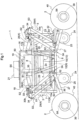
Fig. 1 shows an embodiment of the present invention, and is a side view of a hydraulic robot serving as one example of a work vehicle. -
Fig. 2 shows a plan view of the work vehicle. -
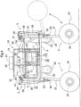
Fig. 3 shows a front view of the work vehicle. -
Fig. 4 shows a side view of the work vehicle in a state in which traveling devices have been lowered. -
Fig. 5 shows a front view of the work vehicle in a state in which the traveling devices have been lowered. -
Fig. 6 shows a front view of the work vehicle in a state in which the work vehicle travels along a step. - An embodiment of a work vehicle according to the present invention will be described below with reference to the drawings. In the present embodiment, a hydraulic robot is disclosed as an example of a work vehicle, but the hydraulic robot will be referred to as a "work vehicle" in the following description.
- Also, in the following description, the right side in
Figs. 1 and2 corresponds to the front side of the vehicle body of the work vehicle, and the left side inFigs. 1 and2 corresponds to the rear side of the vehicle body of the work vehicle. - As shown in
Figs. 1 to 3 , the work vehicle has a substantially rectangular frame-like vehicle body 1 (simply referred to as a "main body 1" hereinafter) that supports the entire vehicle, a plurality of (four in more specific) travelingdevices 2 located at the front and rear respectively on both right and left sides of thevehicle body 1, a plurality of bending (flexion) link mechanisms 3 (serving as an example of a raising/lowering support mechanism) that support therespective traveling devices 2 on themain body 1 such that it is possible to individually raise or lower the travelingdevices 2, a plurality of hydraulically drivendrive mechanisms 4 capable of individually changing the posture of the plurality of bendinglink mechanisms 3, and a hydraulicoil supply device 5 that supplies hydraulic oil to thedrive mechanisms 4. - The
main body 1 includes a plate-like base 6 that supports the entire body of the vehicle and supports a bottom portion of themain body 1, and a plurality offrame members 7 that extend upward from a plurality of appropriately dispersed locations along a peripheral edge portion of thebase 6. Theframe members 7 are formed in a state extending upward from locations corresponding to each of the plurality of travelingdevices 2. Upper portions of the plurality offrame members 7 are connected to each other by an upper connectingbody 8. The upper connectingbody 8 is formed in a ring shape extending along the outer peripheral portion of thebase 6. In this way, the upper and lower sides of the plurality offrame members 7 are integrally connected to each other to thereby constitute a rigid frame member. Therefore, in themain body 1, a bottom portion is formed by the plate-like base 6, and a framework is formed by the plurality offrame members 7 and provided in an approximately box-like shape having an open top. - The hydraulic
oil supply device 5 includes ahydraulic supply source 9 that feeds out hydraulic oil toward thedrive mechanisms 4, andvalve mechanisms 10 that control the hydraulic oil supplied from thehydraulic supply source 9 to thedrive mechanisms 4. More specifically, although not described in detail, thehydraulic supply source 9 includes an engine 11 (serving as an example of a power device that drives a hydraulic pump) and ahydraulic pump 12 driven by theengine 11, which are integrally connected to each other. Hydraulic oil is fed out and supplied to thedrive mechanisms 4 through thevalve mechanisms 10 by thehydraulic pump 12, which is driven by theengine 11. Thevalve mechanisms 10 include a plurality ofhydraulic control valves 13 that perform supply/discharge of hydraulic oil to/from thedrive mechanisms 4, or adjustment of a flow rate or the like. - The hydraulic
oil supply device 5 is provided in themain body 1 at an intermediate location in the front-rear direction of the vehicle body. - The hydraulic
pressure supply source 9 constituting a main part of the hydraulicoil supply device 5 is mounted on and supported by thebase 6 in a state located in themain body 1 at an intermediate location in the front-rear direction of the vehicle body. As shown inFig. 3 , anengine support frame 15 is supported on thebase 6 through ananti-vibration member 14. The hydraulicpressure supply source 9 is mounted on and supported by theengine support frame 15. Because theengine support frame 15 is supported in an anti-vibration manner, vibration of theengine 11 is less likely to be transmitted to thebase 6. Further, theengine support frame 15 includesvertical frame portions 15a at locations on both right and left sides in both front and rear side portions, and is capable of protecting thehydraulic supply source 9 when, for example, the vehicle body rolls over. - As shown in
Figs. 1 and3 , themain body 1 includes asupport base 16 that extends upward from thebase 6 so as to straddle thehydraulic supply source 9 in the vicinity of an intermediate portion in the front-rear direction. Thesupport base 16 includes a pair of front and rear gate-shapedmembers 17 formed in a gate-like shape in a front view so as to straddle thehydraulic supply source 9 with a space between the gate-shapedmembers 17 in the front-rear direction, a right-left pair of front-rear oriented connectingmembers 18 that connect upper end portions of the front-rear pair of gate-shapedmembers 17 to each other on both right and left sides, and a mountingbase 19 supported on the upper side of the right-left connectingmembers 18. Lower ends of the front-rear pair of gate-shapedmembers 17 are fixed to thebase 6. - The
valve mechanisms 10 are supported on the upper-lower intermediate portions of thesupport base 16. That is, as shown inFig. 1 , asupport bracket 20 is provided spanning across upper-lower intermediate portions of a front sidevertical portion 17a of the gate-shapedmember 17 and upper-lower intermediate portions of a rear sidevertical portion 17a of the gate-shapedmember 17. As shown inFig. 3 ,support brackets 20 are provided on both right and left sides of thesupport base 16, and thevalve mechanisms 10 are individually attached to thesupport brackets 20 on both right and left sides respectively. - Therefore, the
hydraulic supply source 9 and thevalve mechanisms 10 that constitute the hydraulicoil supply device 5 are provided in themain body 1 at an intermediate location in the front-rear direction of the vehicle body. - Also, a
hydraulic oil tank 50 is disposed in themain body 1 above the intermediate location in the front-rear direction of the vehicle body, that is, above thehydraulic supply source 9 and thevalve mechanisms 10 that constitute the hydraulicoil supply device 5. By disposing thehydraulic oil tank 50 above and the hydraulicoil supply device 5 in the open space below in this way, thehydraulic supply source 9 and thevalve mechanisms 10 that constitute the hydraulicoil supply device 5 are located at a comparatively lower location in themain body 1, so that air is unlikely to enter thehydraulic supply source 9 and thevalve mechanisms 10, and therefore it is possible to stabilize hydraulic control. Note that, in a case where lowering of the center of gravity of the vehicle is emphasized, a configuration may be adopted in which thehydraulic oil tank 50 is disposed in themain body 1 below the intermediate location in the front-rear direction of the vehicle body, and thehydraulic supply source 9 and thevalve mechanisms 10 that constitute the hydraulicoil supply device 5 are disposed above thehydraulic oil tank 50. - As shown in
Figs. 1 ,2 and3 , acontrol device 21 that controls operation of thevalve mechanisms 10 is mounted on and supported by the mountingbase 19 provided in the upper end portion of thesupport base 16. Although the control operation of thecontrol device 21 is not described in detail, thecontrol device 21 controls the state of supply of hydraulic oil to thedrive mechanisms 4 in thevalve mechanisms 10 based on control information inputted by a manual input device (not shown) or control information that has been set in advance and stored. Abattery 23 is mounted and supported, through adedicated mounting base 22, at a location on the front side of the vehicle body in thebase 6. Power can be supplied to thecontrol device 21 by thebattery 23. - A plurality of
auxiliary wheels 24 are provided below themain body 1. That is, as shown inFigs. 1 and3 , on the lower face side of thebase 6, a total of fourauxiliary wheels 24 are provided in a state disposed in a dispersed manner at locations on both right and left sides in each of both front and rear side portions of the vehicle. Asupport bracket 25 is attached in a state protruding downward from the lower face of thebase 6, and theauxiliary wheels 24 are supported on thesupport bracket 25 so as to be freely rotatable around a lateral axis. By providing suchauxiliary wheels 24, for example, all of the travelingdevices 2 can easily be moved manually by storing the travelingdevices 2 upward as indicated by the virtual line inFIG 4 . - Next is a description of the support structure for supporting the traveling
devices 2 on themain body 1. - Each of the plurality (four in more specific) of bending
link mechanisms 3 includes afirst link 26 having one end supported on themain body 1 such that thefirst link 26 is capable of swinging around a lateral axis, and asecond link 27 having one end supported on the other end of thefirst link 26 such that the second link is capable of swinging around a lateral axis, with a travelingdevice 2 supported on the other end of thesecond link 27. - A plurality (four) of the
drive mechanisms 4 are provided corresponding to each of the plurality of bendinglink mechanisms 3, and eachdrive mechanism 4 includes a firsthydraulic cylinder 28 capable of changing the swinging posture of thefirst link 26 with respect to themain body 1, and a secondhydraulic cylinder 29 capable of changing the swinging posture of thesecond link 27 with respect to thefirst link 26. Eachdrive mechanism 4 changes the posture of the correspondingbending link mechanism 3 while maintaining a state in which thefirst link 26 and thesecond link 27 in thebending link mechanism 3 bend toward the intermediate side in the front-rear direction of the vehicle body. - More specifically, as shown in
Figs. 1 to 3 andFig. 5 , on both sides at the front and rear of themain body 1, a laterally orientedsupport shaft 31 that extends in the lateral direction over the entire width in the lateral direction of the vehicle body is fixed, through brackets 30 (brackets body 8 that connects the upper portions of theframe members 7 to each other. Among the four bendinglink mechanisms 3, apivot boss portion 32 of eachfirst link 26 in the right and left bendinglink mechanisms 3 located on the front side are externally fitted in a rotatable manner on thesupport shaft 31 on the front side. Among the four bendinglink mechanisms 3, apivot boss portion 32 of eachfirst link 26 in the right and left bendinglink mechanisms 3 located on the rear side are externally fitted in a rotatable manner on thesupport shaft 31 on the rear side. - As shown in
Figs. 1 and2 , afirst bracket 33 and asecond bracket 34 are provided in an integrated manner in the respectivepivot boss portions 32 of thefirst links 26, such that thefirst bracket 33 and thesecond bracket 34 are at different positions in the circumferential direction. The firsthydraulic cylinder 28 is pivotally connected across thefirst bracket 33 and a vehicle-side bracket 35 provided at a location spaced to the inside in the front-rear direction of the vehicle body from thesupport shaft 31 in the upper connectingbody 8. The secondhydraulic cylinder 29 is pivotally connected across thesecond bracket 34 and a link-side bracket 36 provided in an intermediate portion of thesecond link 27. Note that, in thepivot boss portion 32 supported on thesupport shaft 31 on the front side, thefirst bracket 33 and thesecond bracket 34 are provided in a state separated from each other in the lateral direction. - When the first
hydraulic cylinder 28 is extended and contracted in a state where operation of the secondhydraulic cylinder 29 has been stopped, each of thefirst links 26, thesecond links 27 and the travelingdevices 2 swing in unison with each other around alateral axis X 1 of thesupport shaft 31. When the secondhydraulic cylinder 29 is extended and contracted in a state where operation of the firsthydraulic cylinder 28 has been stopped, while the posture of thefirst links 26 is constantly maintained, thesecond links 27 and the travelingdevices 2 swing in unison with each other around a lateral axis X2 where thefirst links 26 and thesecond links 27 are connected (see the virtual line inFig. 4 ). - As shown in
Fig. 3 , afirst angle sensor 37 that detects the pivot angle of thefirst link 26 with respect to thesupport shaft 31 is provided on the lateral side of thepivot boss portion 32 with respect to thesupport shaft 31 of thefirst link 26. Asecond angle sensor 38 that detects the relative angle of thefirst link 26 and thesecond link 27 is provided in a pivot support portion where thefirst link 26 and thesecond link 27 are pivotally connected. -
Figs. 1 and3 show a state in which, in each of the plurality of bendinglink mechanisms 3, the firsthydraulic cylinder 28 and the secondhydraulic cylinder 29 are each in their most retracted state. In other words,Figs. 1 and3 show a state in which all of the travelingdevices 2 are closest to the main body 1 (that is, a state where the vehicle height is as low as possible). - The solid lines in
Fig. 4 , andFig. 5 , show a state in which, in each of the plurality of bendinglink mechanisms 3, the firsthydraulic cylinder 28 is operated such that thefirst link 26 is in a vertical posture and the secondhydraulic cylinder 29 is operated such that thesecond link 27 is in a vertical posture. In other words, the solid lines inFig. 4 , andFig. 5 , show a state in which themain body 1 is separated as much as possible from all of the traveling devices 2 (that is, a state where the vehicle height is as high as possible). -
Fig. 6 shows a state in which, in two of the bendinglink mechanisms 3 located on the right side, the firsthydraulic cylinder 28 is operated such that thefirst link 26 is in a vertical posture and the secondhydraulic cylinder 29 is operated such that thesecond link 27 is in a vertical posture, and in two of the bendinglink mechanisms 3 located on the left side, the firsthydraulic cylinder 28 and the secondhydraulic cylinder 29 are each in their most retracted state. - As shown in
Figs. 1 and3 , the secondhydraulic cylinder 29 is provided across thesecond bracket 34, which protrudes to the outside in the front-rear direction of the vehicle body from thepivot boss portion 32, and a location to the outside in the front-rear direction of the vehicle body in the vertical posture of thesecond link 27. By providing the secondhydraulic cylinder 29 in this way, when bending thebending link mechanism 3, a state is maintained where anintermediate bending portion 3A of thebending link mechanism 3 bends toward the intermediate side in the front-rear direction of the vehicle body. - The first
hydraulic cylinder 28 and the secondhydraulic cylinder 29 corresponding to each of the two bendinglink mechanisms 3 located on the right side of the vehicle body are connected to thevalve mechanism 10 located on the right side of the vehicle body by hydraulic piping not shown. The firsthydraulic cylinder 28 and the secondhydraulic cylinder 29 corresponding to the two bendinglink mechanisms 3 located on the left side of the vehicle body are connected to thevalve mechanism 10 located on the left side of the vehicle body by hydraulic piping not shown. - Hydraulic oil is supplied from the
hydraulic supply source 9 to the firsthydraulic cylinder 28 and the secondhydraulic cylinder 29 of each of the plurality of bendinglink mechanisms 3 through thevalve mechanism 10. Thehydraulic control valve 13 provided in thevalve mechanism 10 supplies and discharges the hydraulic oil, and thus the firsthydraulic cylinder 28 and the secondhydraulic cylinder 29 can be operated to extend and contract. Thehydraulic control valve 13 is controlled by thecontrol device 21. Thecontrol device 21 can change thebending link mechanisms 3 to a desired posture by performing control such that detection values of thefirst angle sensor 37 and thesecond angle sensor 38 reach target values. -
Hydraulic motors 39 that drive the travelingdevices 2 are provided individually in each of the travelingdevices 2. That is, each of the fourtraveling devices 2 includes awheel 40 supported so as to be capable of rotating around a lateral axis, and ahydraulic motor 39, which is built into a bearingportion 41 of thewheel 40. Each travelingdevice 2 can rotationally drive awheel 40 individually by operating itshydraulic motor 39. - Each of the two
hydraulic motors 39 provided in the two travelingdevices 2 located on the right side of the vehicle body is connected to thevalve mechanism 10 on the right side by hydraulic piping not shown, and each of the twohydraulic motors 39 provided in the two travelingdevices 2 located on the left side of the vehicle body is connected to thevalve mechanism 10 on the left side by hydraulic piping not shown. Hydraulic oil is supplied from thehydraulic supply source 9 to eachhydraulic motor 39 through the right and leftvalve mechanisms 10 respectively. - It is possible to change the rotational speed of the
hydraulic motor 39, that is, thewheel 40, by adjusting the flow rate of the hydraulic oil with thehydraulic control valve 13 provided in thevalve mechanism 10 corresponding to thehydraulic motor 39. Thehydraulic control valve 13 is controlled by thecontrol device 21 based on control information inputted by a manual operation or control information that has been set in advance and stored, or the like. - As shown in
Fig. 1 , this work vehicle includes various sensors. Specifically, a first cap-side pressure sensor S1 and a first head-side pressure sensor S2 are provided in each firsthydraulic cylinder 28, and a second cap-side pressure sensor S3 and a second head-side pressure sensor S4 are provided in each secondhydraulic cylinder 29. - The first cap-side pressure sensor S1 detects the hydraulic pressure of a cap-side chamber of the first
hydraulic cylinder 28. The first head-side pressure sensor S2 detects the hydraulic pressure of a head-side chamber on the opposite side as the cap of the firsthydraulic cylinder 28. - The second cap-side pressure sensor S3 detects the hydraulic pressure of a cap-side chamber of the second
hydraulic cylinder 29. The second head-side pressure sensor S4 detects the hydraulic pressure of a head-side chamber on the opposite side as the cap of the secondhydraulic cylinder 29. - Note that the installation locations of the respective
pressure sensors S 1, S2, S3 and S4 are not limited to those described above. It is sufficient that the respective pressure sensors S1, S2, S3 and S4 are able to detect (estimate) the hydraulic pressure of the corresponding cap-side chamber or head-side chamber, and these sensors may be provided in piping between thevalve mechanism 10 and the corresponding cap-side chamber or head-side chamber. - The force required to support the
main body 1 is calculated based on the detection results of these sensors, and based on the results of that calculation, the supply of hydraulic oil to the firsthydraulic cylinder 28 and the secondhydraulic cylinder 29 respectively is controlled. Specifically, based on the detection value of the first cap-side pressure sensor S1 and the detection value of the first head-side pressure sensor S2, cylinder thrust of the firsthydraulic cylinder 28 is calculated from the differential pressure between the cap-side chamber and the head-side chamber of the firsthydraulic cylinder 28. Also, based on the detection value of the second cap-side pressure sensor S3 and the detection value of the second head-side pressure sensor S4, cylinder thrust of the secondhydraulic cylinder 29 is calculated in the same manner as for the firsthydraulic cylinder 28. - The work vehicle also includes an acceleration sensor S5. Based on the detection result of the acceleration sensor S5, inclination of the
main body 1 to the front, rear, left, and right is detected, and the posture of themain body 1 is controlled based on those results. That is, the supply of hydraulic oil to the firsthydraulic cylinder 28 and the secondhydraulic cylinder 29 respectively is controlled such that the posture of themain body 1 becomes a target posture. - Note that the method of detecting cylinder thrust is not limited to the above-described method in which cylinder thrust is calculated by pressure sensors provided on the cap side and the head side (the side opposite to the cap). It is sufficient that cylinder thrust can be detected, and a configuration may be adopted in which cylinder thrust is detected by providing a sensor that detects force at the tip of a cylinder rod.
- The work vehicle also includes rotation sensors S6 that detect the rotational speed of the
hydraulic motors 39 that drive the travelingdevices 2. The rotational speed of eachwheel 40 is calculated based on the detection results of these rotation sensors S6. The supply of hydraulic oil to thehydraulic motors 39 is controlled based on the calculated rotational speed of thewheels 40 so that the rotational speed of thewheels 40 becomes a target value. - As described above, the traveling
devices 2 are supported through the bendinglink mechanisms 3, and the posture of the bendinglink mechanisms 3 is changed by thehydraulic cylinders drive mechanisms 4. This configuration is not likely to be affected by moisture, fine dust, or the like, and is suitable for agricultural work. - Also, as described above, the plurality of
drive mechanisms 4 are disposed distributed in the front and rear respectively on both right and left sides of themain body 1, in a state corresponding to the plurality of bendinglink mechanisms 3. Also, because the hydraulicoil supply device 5 is provided in themain body 1 at an intermediate position in the front-rear direction of the vehicle body, the distance from the hydraulicoil supply device 5 is equal respectively for thedrive mechanisms 4 located on the front side of the vehicle and thedrive mechanisms 4 located on the rear side of the vehicle. That is, the length of the hydraulic pipe for supplying hydraulic oil to eachdrive mechanism 4 can be made equal. As a result, variations in characteristics such as pressure, flow rate and temperature of the hydraulic oil supplied to eachdrive mechanism 4 can be reduced. - The
drive mechanism 4 uses a large amount of hydraulic oil, and the hydraulicoil supply device 5 supplies hydraulic oil to the plurality ofdrive mechanisms 4, so that the hydraulicoil supply device 5 becomes a large and heavy device. Because the hydraulicoil supply device 5 having such a large size is provided in themain body 1 at an intermediate position in the front-rear direction of the vehicle, the weight balance in the front-rear direction of the overall vehicle is good, and the posture of the vehicle can be easily stabilized. - Also, as described above, the
hydraulic supply source 9 is mounted on and supported by thebase 6 that supports the entire vehicle in the vehicle body. The hydraulic oil fed out from thehydraulic pressure source 9 is supplied to thedrive mechanisms 4 in a state where this supply is controlled by thevalve mechanisms 10. Although thehydraulic supply source 9 of the hydraulicoil supply device 5 is a large device in order to feed out a large amount of hydraulic oil, this sort ofhydraulic supply source 9 is mounted on and supported by a base. Thebase 6 is a rigid component that supports the entire vehicle, and can stably support thehydraulic supply source 9, which is a large device. - The following working mode is a usage example. For example, a work device is mounted on and supported by the
main body 1, and travelingdevices 2 contact the ground in passages on both right and left sides of a crop row so that work is performed while themain body 1 travels in a state straddling over the crop row. By changing the location of themain body 1 according to the growing conditions of the crop, it becomes easy to carry out work of planting the crop, work of spreading fertilizers and drugs and the like, and work of harvesting after growing, and the like (seeFig. 6 ). It is also possible to travel in a state in which the vehicle contacts the ground on both right and left sides in a location where large steps exist. Furthermore, because the four bendinglink mechanisms 3 can bend individually, it is possible to move by the travelingdevices 2 climbing over the steps one by one, and thus it is possible to climb over the steps by autonomous traveling. -
- (1) In the above embodiment, a configuration is adopted in which the
bending link mechanisms 3 are supported on theframe members 7 that extend upward from thebase 6, but instead of this configuration, a configuration may be adopted in which thebending link mechanisms 3 are directly supported on thebase 6, or a configuration may be adopted in which thebending link mechanisms 3 are supported on a frame member that extends downward from thebase 6. - (2) In the above embodiment, a configuration is adopted in which each
drive mechanism 4 includes the firsthydraulic cylinder 28 and the secondhydraulic cylinder 29, but instead of this configuration, a not claimed configuration may be adopted in which a hydraulic motor is provided at the swing fulcrum of each bendinglink mechanism 3, and the posture of each bendinglink mechanism 3 is changed by the hydraulic motors. - (3) In the above embodiment, a configuration is adopted in which the
auxiliary wheels 24 are supported so as to be freely rotatable. However, a configuration may be adopted in which theauxiliary wheels 24 are rotationally driven, or a configuration may be adopted in which suchauxiliary wheels 24 are not provided. - (4) In the above embodiment, a configuration is adopted in which the traveling
devices 2 are driven by thehydraulic motors 39, but instead of this configuration, a configuration may be adopted in which, for example, the power of theengine 11 is supplied to thewheels 40 through a mechanical transmission mechanism such as a chain transmission mechanism. - (5) In the above embodiment, a configuration is adopted in which each traveling
device 2 includes onewheel 40, but instead of this configuration, a configuration may be adopted in which a crawler traveling device in which a crawler belt is wound around a plurality of wheels is used as a traveling device. - (6) In the above embodiment, a configuration is adopted in which the hydraulic
oil supply device 5 is provided in themain body 1 at an intermediate position in the front-rear direction of the vehicle body, but the present invention is not limited to this configuration. For example, the hydraulicoil supply device 5 can also be provided somewhere other than an intermediate position in the front-rear direction of the vehicle body, between thelink mechanisms 3 on the front side in the front-rear direction of the vehicle body and thelink mechanisms 3 on the rear side in the front-rear direction of the vehicle body. - (7) In the above embodiment, the bending
link mechanisms 3 are supported on an upper portion of themain body 1, in other words, supported on an upper portion of theframe members 7. In this case, the location where thelink mechanisms 3 are connected to themain body 1 is set to a high location in themain body 1. Because themain body 1 is supported through thelink mechanisms 3 at a high location, the location of the center of gravity is set as low as possible relative to the support location of themain body 1 in order to make it possible to improve posture stability. However, the support location of the link mechanisms is not limited to the above configuration, and may be, for example, in an intermediate portion or a lower portion of themain body 1. When thelink mechanisms 3 are supported on a lower portion of themain body 1, the height of the vehicle can be increased, and therefore it becomes possible to climb over or straddle higher obstacles. - (8) In the above embodiment, a configuration is adopted in which the
control device 21 is supported on the upper portion of thesupport base 16, and thevalve mechanisms 10 are supported on the upper-lower intermediate portions of thesupport base 16. However, instead of this configuration, a configuration may be adopted in which thecontrol device 21 and thevalve mechanisms 10 are each supported on thebase 6. - (9) In the above embodiment, a configuration is adopted in which a state is maintained in which the
intermediate bending portions 3A of the bendinglink mechanisms 3 bend toward the intermediate side in the front-rear direction of the vehicle body. However, instead of this configuration, a not claimed configuration may be adopted in which theintermediate bending portions 3A bend toward the outside in the front-rear direction of the vehicle body. - The present invention is applicable to an agricultural work vehicle.
-
- 1: vehicle body (main body)
- 2: traveling device
- 3: bending link mechanism (raising/lowering support mechanism)
- 3A: intermediate bending portion
- 4: drive mechanism
- 5: hydraulic oil supply device
- 6: base
- 7: frame member
- 9: hydraulic supply source
- 10: valve mechanism
- 11: engine (power device that drives hydraulic pump)
- 12: hydraulic pump
- 16: support base
- 21: control device
- 24: auxiliary wheel
- 26: first link
- 27: second link
- 28: first hydraulic cylinder
- 29: second hydraulic cylinder
- 39: hydraulic motor
- X1: lateral axis
- X2: lateral axis
Claims (8)
- A work vehicle, comprising:a vehicle body (1);a plurality of traveling devices (2) located on both right and left sides of the vehicle body (1);a plurality of bending link mechanisms (3) that support the respective traveling devices (2) on the vehicle body (1) such that the traveling devices (2) can be individually raised or lowered; anda plurality of drive mechanisms (4) capable of individually changing posture of the bending link mechanisms (3);the drive mechanisms (4) being able to change the posture of the bending link mechanisms (3) while maintaining a state in which intermediate bending portions (3A) of the bending link mechanisms bend toward an intermediate side in a front-rear direction of the vehicle body (1); characterized in thateach of the bending link mechanisms (3) includes a first link (26) having one end supported on the vehicle body (1) such that the first link (26) is capable of swinging around a lateral axis, and a second link (27) having one end supported on the other end of the first link (26) such that the second link (27) is capable of swinging around a lateral axis, with the traveling device (2) supported on the other end of the second link (27),each of the drive mechanisms (4) includes a first hydraulic cylinder (28) capable of changing the swinging posture of the first link (26) with respect to the vehicle body (1), and a second hydraulic cylinder (29) capable of changing the swinging posture of the second link (27) with respect to the first link (26), andeach of the drive mechanisms (4) changes the posture of the bending link mechanism (3) while maintaining a state in which the first link (26) and the second link (27) in the bending link mechanism (3) bend toward the intermediate side in the front-rear direction of the vehicle body (1).
- The work vehicle according to claim 1,wherein in the vehicle body (1), there is provided a hydraulic supply source (9) that feeds out hydraulic oil toward the plurality of drive mechanisms (4), andthe hydraulic supply source (9) is mounted on and supported by a base (6) that supports the entire vehicle in the vehicle body (1).
- The work vehicle according to any one of claims 1 to 2,
wherein hydraulic motors that drive the traveling devices (2) are provided individually in the traveling devices (2). - The work vehicle according to any one of claims 1 to 3,
wherein a plurality of auxiliary wheels (24) are provided in a lower portion of the vehicle body (1). - The work vehicle according to any one of claims 1 to 4,wherein the traveling devices (2) and the drive mechanisms (4) are hydraulically driven,the work vehicle including a hydraulic supply source (9) that feeds out hydraulic oil toward the traveling devices (2) and the drive mechanisms (4), anda valve mechanism (10) that controls hydraulic oil supplied from the hydraulic supply source (9) to the drive mechanisms (4).
- The work vehicle according to claim 5,
wherein the hydraulic supply source (9) includes a hydraulic pump (12) and a power device (11) that drives the hydraulic pump (12). - The work vehicle according to claim 5 or 6,
wherein hydraulic motors that drive the traveling devices (2) are provided individually in the traveling devices (2). - The work vehicle according to any one of claims 5 to 7,wherein the vehicle body (1) includes a support base (16) that extends upward from a base (6) so as to straddle the hydraulic supply source (9), and a control device (21) that controls operation of the valve mechanism (10),the control device (21) being supported on an upper portion of the support base (16), and the valve mechanism (10) being supported on upper-lower intermediate portions of the support base (16).
Applications Claiming Priority (3)
| Application Number | Priority Date | Filing Date | Title |
|---|---|---|---|
| JP2016249938A JP6765294B2 (en) | 2016-12-22 | 2016-12-22 | Hydraulic robot |
| JP2016249937A JP6611697B2 (en) | 2016-12-22 | 2016-12-22 | Work vehicle |
| PCT/JP2017/039350 WO2018116642A1 (en) | 2016-12-22 | 2017-10-31 | Working vehicle |
Publications (3)
| Publication Number | Publication Date |
|---|---|
| EP3560803A1 EP3560803A1 (en) | 2019-10-30 |
| EP3560803A4 EP3560803A4 (en) | 2020-09-09 |
| EP3560803B1 true EP3560803B1 (en) | 2023-10-04 |
Family
ID=62627039
Family Applications (1)
| Application Number | Title | Priority Date | Filing Date |
|---|---|---|---|
| EP17883079.0A Active EP3560803B1 (en) | 2016-12-22 | 2017-10-31 | Working vehicle |
Country Status (4)
| Country | Link |
|---|---|
| US (1) | US11040589B2 (en) |
| EP (1) | EP3560803B1 (en) |
| CN (1) | CN109923032B (en) |
| WO (1) | WO2018116642A1 (en) |
Families Citing this family (8)
| Publication number | Priority date | Publication date | Assignee | Title |
|---|---|---|---|---|
| CN110494349B (en) * | 2017-03-29 | 2022-12-13 | 株式会社久保田 | Working vehicle |
| JP6910547B2 (en) * | 2018-05-16 | 2021-07-28 | 三菱電機株式会社 | Mobile trolley |
| ES2985198T3 (en) * | 2020-09-10 | 2024-11-04 | Monchiero & C S N C | Harvesting machine for harvesting fruits from the ground and its control method |
| CN114348144B (en) * | 2021-12-30 | 2023-03-14 | 华晓精密工业(苏州)有限公司 | AGV offline mechanism and AGV |
| IT202200004445A1 (en) * | 2022-03-09 | 2023-09-09 | Francesco Betti | DUMPER FOR THE TRANSPORT OF PRODUCTS |
| GB2630623A (en) * | 2023-05-31 | 2024-12-04 | Moov Electric Vehicles Gmbh | Compact electric vehicle |
| KR102803767B1 (en) * | 2023-08-16 | 2025-05-02 | 국립금오공과대학교 산학협력단 | Driving vehicles for driving on uneven terrain |
| KR20250073953A (en) * | 2023-11-20 | 2025-05-27 | 현대자동차주식회사 | Link structure of wheel |
Citations (1)
| Publication number | Priority date | Publication date | Assignee | Title |
|---|---|---|---|---|
| DE29712694U1 (en) * | 1997-07-17 | 1997-09-11 | Zweiweg Schneider Gmbh & Co. Kg, 42799 Leichlingen | Road vehicle |
Family Cites Families (29)
| Publication number | Priority date | Publication date | Assignee | Title |
|---|---|---|---|---|
| US4102424A (en) | 1977-07-08 | 1978-07-25 | Hydraulics Unlimited Manufacturing Co. | Tag wheel lift |
| GB2022995B (en) | 1978-06-10 | 1982-10-06 | Pek Sun Chang | Adjustable height support apparatus |
| JPH0174907U (en) * | 1987-11-09 | 1989-05-22 | ||
| JPH0692231B2 (en) * | 1990-11-29 | 1994-11-16 | 三弘機械株式会社 | Car body horizontal holding device |
| US5390752A (en) * | 1993-03-31 | 1995-02-21 | Scarab Manufacturing And Leasing, Inc. | Drive train suspension system |
| JPH07276951A (en) * | 1994-04-15 | 1995-10-24 | Toyota Autom Loom Works Ltd | Road surface inclination angle display device |
| US5515934A (en) * | 1994-10-17 | 1996-05-14 | Davis; Stuart D. | Agile versatile mobile robot body |
| CN1161725A (en) * | 1994-11-08 | 1997-10-08 | 株式会社小松制作所 | Working vehicle |
| JPH09142347A (en) | 1995-11-24 | 1997-06-03 | Mitsubishi Heavy Ind Ltd | Rough terrain moving device |
| JPH09315127A (en) * | 1996-06-04 | 1997-12-09 | Toyo Umpanki Co Ltd | Horizontal control method for deck |
| JPH11208538A (en) * | 1998-01-28 | 1999-08-03 | Komatsu Engineering Kk | Rough terrain travelling working vehicle |
| US6206125B1 (en) * | 2000-02-02 | 2001-03-27 | Equipment Technologies, Inc. | Apparatus and method for locking an adjustable width axle assembly of a crop sprayer |
| US6311795B1 (en) | 2000-05-02 | 2001-11-06 | Case Corporation | Work vehicle steering and suspension system |
| JP4023776B2 (en) * | 2001-11-08 | 2007-12-19 | 三井造船株式会社 | Car body level control method and apparatus for transport cart |
| JP4669413B2 (en) * | 2006-03-01 | 2011-04-13 | 株式会社クボタ | Combine posture detection device and combine posture control device |
| JP2009214713A (en) * | 2008-03-11 | 2009-09-24 | Yanmar Co Ltd | Traveling vehicle for irregular ground |
| CN102001371B (en) * | 2010-11-23 | 2012-05-23 | 南京航空航天大学 | Hydraulically-driven four-foot robot |
| JP2014234138A (en) | 2013-06-05 | 2014-12-15 | スズキ株式会社 | Movable body |
| CN105472965B (en) * | 2013-08-09 | 2018-07-24 | 洋马株式会社 | The posture control device of working rig |
| JP2015054576A (en) * | 2013-09-11 | 2015-03-23 | 聰 永井 | Jack for trailer |
| US9079470B2 (en) * | 2013-10-14 | 2015-07-14 | Agco Corporation | Vehicle with chassis height adjustment |
| JP6131181B2 (en) * | 2013-12-20 | 2017-05-17 | ヤンマー株式会社 | Work vehicle attitude control device |
| GB201401236D0 (en) * | 2014-01-24 | 2014-03-12 | Ihc Engineering Business Ltd | Trenching apparatus |
| US9346497B2 (en) * | 2014-04-09 | 2016-05-24 | Hagie Manufacturing Company | Variable tread width vehicle |
| JP6280432B2 (en) * | 2014-04-28 | 2018-02-14 | ヤンマー株式会社 | Traveling vehicle |
| CA2946369C (en) | 2014-04-28 | 2017-12-12 | Yanmar Co., Ltd. | Traveling vehicle |
| CN105835969B (en) * | 2016-04-13 | 2017-12-26 | 河北农业大学 | Agricultural electric chassis with double-torsion parallel four-connecting-rod independent suspension |
| US11524735B2 (en) * | 2017-03-29 | 2022-12-13 | Kubota Corporation | Work vehicle |
| CN110494349B (en) * | 2017-03-29 | 2022-12-13 | 株式会社久保田 | Working vehicle |
-
2017
- 2017-10-31 WO PCT/JP2017/039350 patent/WO2018116642A1/en not_active Ceased
- 2017-10-31 CN CN201780069339.9A patent/CN109923032B/en active Active
- 2017-10-31 US US16/466,456 patent/US11040589B2/en active Active
- 2017-10-31 EP EP17883079.0A patent/EP3560803B1/en active Active
Patent Citations (1)
| Publication number | Priority date | Publication date | Assignee | Title |
|---|---|---|---|---|
| DE29712694U1 (en) * | 1997-07-17 | 1997-09-11 | Zweiweg Schneider Gmbh & Co. Kg, 42799 Leichlingen | Road vehicle |
Also Published As
| Publication number | Publication date |
|---|---|
| US20190389268A1 (en) | 2019-12-26 |
| EP3560803A1 (en) | 2019-10-30 |
| US11040589B2 (en) | 2021-06-22 |
| WO2018116642A1 (en) | 2018-06-28 |
| EP3560803A4 (en) | 2020-09-09 |
| CN109923032B (en) | 2022-06-03 |
| CN109923032A (en) | 2019-06-21 |
Similar Documents
| Publication | Publication Date | Title |
|---|---|---|
| EP3560803B1 (en) | Working vehicle | |
| US11498632B2 (en) | Work vehicle | |
| JP6191556B2 (en) | Work vehicle | |
| EP3733488A1 (en) | Work vehicle | |
| JP2020001443A (en) | Work vehicle | |
| JP6241394B2 (en) | Work vehicle | |
| US20230284608A1 (en) | System and method for adjusting the chassis height of a machine | |
| JP7117989B2 (en) | work vehicle | |
| JP2020001440A (en) | Maintenance vehicle | |
| EP4204284B1 (en) | System and method for adjusting the chassis height of a machine | |
| JP6887370B2 (en) | Tractor | |
| JP4835248B2 (en) | Seedling transplanter | |
| JP6815980B2 (en) | Work vehicle | |
| JP6765294B2 (en) | Hydraulic robot | |
| JP6098627B2 (en) | Seedling transplanter | |
| JP6519614B2 (en) | Work vehicle | |
| JP2016119879A5 (en) | ||
| JP6937725B2 (en) | Work platform | |
| JP2020001441A (en) | Work vehicle | |
| JP6611697B2 (en) | Work vehicle | |
| JP2023092156A (en) | work vehicle | |
| EP4169817A1 (en) | Height-adjustable track drive systems and related agricultural vehicles and methods | |
| JP2010075107A (en) | Seedling planter | |
| JP6304414B2 (en) | Seedling transplanter | |
| JP6701112B2 (en) | Work vehicle |
Legal Events
| Date | Code | Title | Description |
|---|---|---|---|
| STAA | Information on the status of an ep patent application or granted ep patent |
Free format text: STATUS: THE INTERNATIONAL PUBLICATION HAS BEEN MADE |
|
| PUAI | Public reference made under article 153(3) epc to a published international application that has entered the european phase |
Free format text: ORIGINAL CODE: 0009012 |
|
| STAA | Information on the status of an ep patent application or granted ep patent |
Free format text: STATUS: REQUEST FOR EXAMINATION WAS MADE |
|
| 17P | Request for examination filed |
Effective date: 20190606 |
|
| AK | Designated contracting states |
Kind code of ref document: A1 Designated state(s): AL AT BE BG CH CY CZ DE DK EE ES FI FR GB GR HR HU IE IS IT LI LT LU LV MC MK MT NL NO PL PT RO RS SE SI SK SM TR |
|
| AX | Request for extension of the european patent |
Extension state: BA ME |
|
| DAV | Request for validation of the european patent (deleted) | ||
| DAX | Request for extension of the european patent (deleted) | ||
| A4 | Supplementary search report drawn up and despatched |
Effective date: 20200810 |
|
| RIC1 | Information provided on ipc code assigned before grant |
Ipc: B60G 17/015 20060101ALI20200804BHEP Ipc: B60G 17/0165 20060101ALI20200804BHEP Ipc: B62D 61/12 20060101AFI20200804BHEP |
|
| STAA | Information on the status of an ep patent application or granted ep patent |
Free format text: STATUS: EXAMINATION IS IN PROGRESS |
|
| 17Q | First examination report despatched |
Effective date: 20211013 |
|
| REG | Reference to a national code |
Ref country code: DE Ref legal event code: R079 Ipc: B60G0003140000 Ref country code: DE Ref legal event code: R079 Ref document number: 602017075047 Country of ref document: DE Free format text: PREVIOUS MAIN CLASS: B62D0061120000 Ipc: B60G0003140000 |
|
| RIC1 | Information provided on ipc code assigned before grant |
Ipc: B62D 61/10 20060101ALI20230309BHEP Ipc: B60G 17/0195 20060101ALI20230309BHEP Ipc: B62D 61/12 20060101ALI20230309BHEP Ipc: B60G 17/0165 20060101ALI20230309BHEP Ipc: B62D 63/02 20060101ALI20230309BHEP Ipc: B60G 7/02 20060101ALI20230309BHEP Ipc: B60G 3/14 20060101AFI20230309BHEP |
|
| GRAP | Despatch of communication of intention to grant a patent |
Free format text: ORIGINAL CODE: EPIDOSNIGR1 |
|
| STAA | Information on the status of an ep patent application or granted ep patent |
Free format text: STATUS: GRANT OF PATENT IS INTENDED |
|
| INTG | Intention to grant announced |
Effective date: 20230426 |
|
| GRAS | Grant fee paid |
Free format text: ORIGINAL CODE: EPIDOSNIGR3 |
|
| GRAA | (expected) grant |
Free format text: ORIGINAL CODE: 0009210 |
|
| STAA | Information on the status of an ep patent application or granted ep patent |
Free format text: STATUS: THE PATENT HAS BEEN GRANTED |
|
| AK | Designated contracting states |
Kind code of ref document: B1 Designated state(s): AL AT BE BG CH CY CZ DE DK EE ES FI FR GB GR HR HU IE IS IT LI LT LU LV MC MK MT NL NO PL PT RO RS SE SI SK SM TR |
|
| REG | Reference to a national code |
Ref country code: GB Ref legal event code: FG4D |
|
| REG | Reference to a national code |
Ref country code: CH Ref legal event code: EP |
|
| REG | Reference to a national code |
Ref country code: IE Ref legal event code: FG4D |
|
| REG | Reference to a national code |
Ref country code: DE Ref legal event code: R096 Ref document number: 602017075047 Country of ref document: DE |
|
| REG | Reference to a national code |
Ref country code: LT Ref legal event code: MG9D |
|
| REG | Reference to a national code |
Ref country code: NL Ref legal event code: MP Effective date: 20231004 |
|
| REG | Reference to a national code |
Ref country code: AT Ref legal event code: MK05 Ref document number: 1617412 Country of ref document: AT Kind code of ref document: T Effective date: 20231004 |
|
| PG25 | Lapsed in a contracting state [announced via postgrant information from national office to epo] |
Ref country code: NL Free format text: LAPSE BECAUSE OF FAILURE TO SUBMIT A TRANSLATION OF THE DESCRIPTION OR TO PAY THE FEE WITHIN THE PRESCRIBED TIME-LIMIT Effective date: 20231004 |
|
| PG25 | Lapsed in a contracting state [announced via postgrant information from national office to epo] |
Ref country code: GR Free format text: LAPSE BECAUSE OF FAILURE TO SUBMIT A TRANSLATION OF THE DESCRIPTION OR TO PAY THE FEE WITHIN THE PRESCRIBED TIME-LIMIT Effective date: 20240105 |
|
| PG25 | Lapsed in a contracting state [announced via postgrant information from national office to epo] |
Ref country code: IS Free format text: LAPSE BECAUSE OF FAILURE TO SUBMIT A TRANSLATION OF THE DESCRIPTION OR TO PAY THE FEE WITHIN THE PRESCRIBED TIME-LIMIT Effective date: 20240204 |
|
| PG25 | Lapsed in a contracting state [announced via postgrant information from national office to epo] |
Ref country code: LT Free format text: LAPSE BECAUSE OF FAILURE TO SUBMIT A TRANSLATION OF THE DESCRIPTION OR TO PAY THE FEE WITHIN THE PRESCRIBED TIME-LIMIT Effective date: 20231004 |
|
| PG25 | Lapsed in a contracting state [announced via postgrant information from national office to epo] |
Ref country code: AT Free format text: LAPSE BECAUSE OF FAILURE TO SUBMIT A TRANSLATION OF THE DESCRIPTION OR TO PAY THE FEE WITHIN THE PRESCRIBED TIME-LIMIT Effective date: 20231004 |
|
| PG25 | Lapsed in a contracting state [announced via postgrant information from national office to epo] |
Ref country code: ES Free format text: LAPSE BECAUSE OF FAILURE TO SUBMIT A TRANSLATION OF THE DESCRIPTION OR TO PAY THE FEE WITHIN THE PRESCRIBED TIME-LIMIT Effective date: 20231004 |
|
| PG25 | Lapsed in a contracting state [announced via postgrant information from national office to epo] |
Ref country code: LT Free format text: LAPSE BECAUSE OF FAILURE TO SUBMIT A TRANSLATION OF THE DESCRIPTION OR TO PAY THE FEE WITHIN THE PRESCRIBED TIME-LIMIT Effective date: 20231004 Ref country code: IS Free format text: LAPSE BECAUSE OF FAILURE TO SUBMIT A TRANSLATION OF THE DESCRIPTION OR TO PAY THE FEE WITHIN THE PRESCRIBED TIME-LIMIT Effective date: 20240204 Ref country code: GR Free format text: LAPSE BECAUSE OF FAILURE TO SUBMIT A TRANSLATION OF THE DESCRIPTION OR TO PAY THE FEE WITHIN THE PRESCRIBED TIME-LIMIT Effective date: 20240105 Ref country code: ES Free format text: LAPSE BECAUSE OF FAILURE TO SUBMIT A TRANSLATION OF THE DESCRIPTION OR TO PAY THE FEE WITHIN THE PRESCRIBED TIME-LIMIT Effective date: 20231004 Ref country code: BG Free format text: LAPSE BECAUSE OF FAILURE TO SUBMIT A TRANSLATION OF THE DESCRIPTION OR TO PAY THE FEE WITHIN THE PRESCRIBED TIME-LIMIT Effective date: 20240104 Ref country code: AT Free format text: LAPSE BECAUSE OF FAILURE TO SUBMIT A TRANSLATION OF THE DESCRIPTION OR TO PAY THE FEE WITHIN THE PRESCRIBED TIME-LIMIT Effective date: 20231004 Ref country code: PT Free format text: LAPSE BECAUSE OF FAILURE TO SUBMIT A TRANSLATION OF THE DESCRIPTION OR TO PAY THE FEE WITHIN THE PRESCRIBED TIME-LIMIT Effective date: 20240205 |
|
| PG25 | Lapsed in a contracting state [announced via postgrant information from national office to epo] |
Ref country code: SE Free format text: LAPSE BECAUSE OF FAILURE TO SUBMIT A TRANSLATION OF THE DESCRIPTION OR TO PAY THE FEE WITHIN THE PRESCRIBED TIME-LIMIT Effective date: 20231004 Ref country code: RS Free format text: LAPSE BECAUSE OF FAILURE TO SUBMIT A TRANSLATION OF THE DESCRIPTION OR TO PAY THE FEE WITHIN THE PRESCRIBED TIME-LIMIT Effective date: 20231004 Ref country code: PL Free format text: LAPSE BECAUSE OF FAILURE TO SUBMIT A TRANSLATION OF THE DESCRIPTION OR TO PAY THE FEE WITHIN THE PRESCRIBED TIME-LIMIT Effective date: 20231004 Ref country code: NO Free format text: LAPSE BECAUSE OF FAILURE TO SUBMIT A TRANSLATION OF THE DESCRIPTION OR TO PAY THE FEE WITHIN THE PRESCRIBED TIME-LIMIT Effective date: 20240104 Ref country code: LV Free format text: LAPSE BECAUSE OF FAILURE TO SUBMIT A TRANSLATION OF THE DESCRIPTION OR TO PAY THE FEE WITHIN THE PRESCRIBED TIME-LIMIT Effective date: 20231004 Ref country code: HR Free format text: LAPSE BECAUSE OF FAILURE TO SUBMIT A TRANSLATION OF THE DESCRIPTION OR TO PAY THE FEE WITHIN THE PRESCRIBED TIME-LIMIT Effective date: 20231004 |
|
| REG | Reference to a national code |
Ref country code: CH Ref legal event code: PL |
|
| REG | Reference to a national code |
Ref country code: BE Ref legal event code: MM Effective date: 20231031 |
|
| PG25 | Lapsed in a contracting state [announced via postgrant information from national office to epo] |
Ref country code: LU Free format text: LAPSE BECAUSE OF NON-PAYMENT OF DUE FEES Effective date: 20231031 |
|
| PG25 | Lapsed in a contracting state [announced via postgrant information from national office to epo] |
Ref country code: LU Free format text: LAPSE BECAUSE OF NON-PAYMENT OF DUE FEES Effective date: 20231031 |
|
| REG | Reference to a national code |
Ref country code: DE Ref legal event code: R097 Ref document number: 602017075047 Country of ref document: DE |
|
| PG25 | Lapsed in a contracting state [announced via postgrant information from national office to epo] |
Ref country code: DK Free format text: LAPSE BECAUSE OF FAILURE TO SUBMIT A TRANSLATION OF THE DESCRIPTION OR TO PAY THE FEE WITHIN THE PRESCRIBED TIME-LIMIT Effective date: 20231004 |
|
| PG25 | Lapsed in a contracting state [announced via postgrant information from national office to epo] |
Ref country code: CH Free format text: LAPSE BECAUSE OF NON-PAYMENT OF DUE FEES Effective date: 20231031 |
|
| PG25 | Lapsed in a contracting state [announced via postgrant information from national office to epo] |
Ref country code: CZ Free format text: LAPSE BECAUSE OF FAILURE TO SUBMIT A TRANSLATION OF THE DESCRIPTION OR TO PAY THE FEE WITHIN THE PRESCRIBED TIME-LIMIT Effective date: 20231004 |
|
| PG25 | Lapsed in a contracting state [announced via postgrant information from national office to epo] |
Ref country code: SK Free format text: LAPSE BECAUSE OF FAILURE TO SUBMIT A TRANSLATION OF THE DESCRIPTION OR TO PAY THE FEE WITHIN THE PRESCRIBED TIME-LIMIT Effective date: 20231004 |
|
| PG25 | Lapsed in a contracting state [announced via postgrant information from national office to epo] |
Ref country code: SM Free format text: LAPSE BECAUSE OF FAILURE TO SUBMIT A TRANSLATION OF THE DESCRIPTION OR TO PAY THE FEE WITHIN THE PRESCRIBED TIME-LIMIT Effective date: 20231004 Ref country code: SK Free format text: LAPSE BECAUSE OF FAILURE TO SUBMIT A TRANSLATION OF THE DESCRIPTION OR TO PAY THE FEE WITHIN THE PRESCRIBED TIME-LIMIT Effective date: 20231004 Ref country code: RO Free format text: LAPSE BECAUSE OF FAILURE TO SUBMIT A TRANSLATION OF THE DESCRIPTION OR TO PAY THE FEE WITHIN THE PRESCRIBED TIME-LIMIT Effective date: 20231004 Ref country code: IT Free format text: LAPSE BECAUSE OF FAILURE TO SUBMIT A TRANSLATION OF THE DESCRIPTION OR TO PAY THE FEE WITHIN THE PRESCRIBED TIME-LIMIT Effective date: 20231004 Ref country code: EE Free format text: LAPSE BECAUSE OF FAILURE TO SUBMIT A TRANSLATION OF THE DESCRIPTION OR TO PAY THE FEE WITHIN THE PRESCRIBED TIME-LIMIT Effective date: 20231004 Ref country code: DK Free format text: LAPSE BECAUSE OF FAILURE TO SUBMIT A TRANSLATION OF THE DESCRIPTION OR TO PAY THE FEE WITHIN THE PRESCRIBED TIME-LIMIT Effective date: 20231004 Ref country code: CZ Free format text: LAPSE BECAUSE OF FAILURE TO SUBMIT A TRANSLATION OF THE DESCRIPTION OR TO PAY THE FEE WITHIN THE PRESCRIBED TIME-LIMIT Effective date: 20231004 Ref country code: CH Free format text: LAPSE BECAUSE OF NON-PAYMENT OF DUE FEES Effective date: 20231031 |
|
| PLBE | No opposition filed within time limit |
Free format text: ORIGINAL CODE: 0009261 |
|
| STAA | Information on the status of an ep patent application or granted ep patent |
Free format text: STATUS: NO OPPOSITION FILED WITHIN TIME LIMIT |
|
| PG25 | Lapsed in a contracting state [announced via postgrant information from national office to epo] |
Ref country code: MC Free format text: LAPSE BECAUSE OF FAILURE TO SUBMIT A TRANSLATION OF THE DESCRIPTION OR TO PAY THE FEE WITHIN THE PRESCRIBED TIME-LIMIT Effective date: 20231004 |
|
| PG25 | Lapsed in a contracting state [announced via postgrant information from national office to epo] |
Ref country code: MC Free format text: LAPSE BECAUSE OF FAILURE TO SUBMIT A TRANSLATION OF THE DESCRIPTION OR TO PAY THE FEE WITHIN THE PRESCRIBED TIME-LIMIT Effective date: 20231004 Ref country code: BE Free format text: LAPSE BECAUSE OF NON-PAYMENT OF DUE FEES Effective date: 20231031 |
|
| 26N | No opposition filed |
Effective date: 20240705 |
|
| GBPC | Gb: european patent ceased through non-payment of renewal fee |
Effective date: 20240104 |
|
| PG25 | Lapsed in a contracting state [announced via postgrant information from national office to epo] |
Ref country code: IE Free format text: LAPSE BECAUSE OF NON-PAYMENT OF DUE FEES Effective date: 20231031 |
|
| PG25 | Lapsed in a contracting state [announced via postgrant information from national office to epo] |
Ref country code: GB Free format text: LAPSE BECAUSE OF NON-PAYMENT OF DUE FEES Effective date: 20240104 |
|
| PG25 | Lapsed in a contracting state [announced via postgrant information from national office to epo] |
Ref country code: SI Free format text: LAPSE BECAUSE OF FAILURE TO SUBMIT A TRANSLATION OF THE DESCRIPTION OR TO PAY THE FEE WITHIN THE PRESCRIBED TIME-LIMIT Effective date: 20231004 |
|
| PG25 | Lapsed in a contracting state [announced via postgrant information from national office to epo] |
Ref country code: SI Free format text: LAPSE BECAUSE OF FAILURE TO SUBMIT A TRANSLATION OF THE DESCRIPTION OR TO PAY THE FEE WITHIN THE PRESCRIBED TIME-LIMIT Effective date: 20231004 Ref country code: IE Free format text: LAPSE BECAUSE OF NON-PAYMENT OF DUE FEES Effective date: 20231031 Ref country code: GB Free format text: LAPSE BECAUSE OF NON-PAYMENT OF DUE FEES Effective date: 20240104 |
|
| PG25 | Lapsed in a contracting state [announced via postgrant information from national office to epo] |
Ref country code: FI Free format text: LAPSE BECAUSE OF FAILURE TO SUBMIT A TRANSLATION OF THE DESCRIPTION OR TO PAY THE FEE WITHIN THE PRESCRIBED TIME-LIMIT Effective date: 20231004 |
|
| PG25 | Lapsed in a contracting state [announced via postgrant information from national office to epo] |
Ref country code: CY Free format text: LAPSE BECAUSE OF FAILURE TO SUBMIT A TRANSLATION OF THE DESCRIPTION OR TO PAY THE FEE WITHIN THE PRESCRIBED TIME-LIMIT; INVALID AB INITIO Effective date: 20171031 |
|
| PG25 | Lapsed in a contracting state [announced via postgrant information from national office to epo] |
Ref country code: HU Free format text: LAPSE BECAUSE OF FAILURE TO SUBMIT A TRANSLATION OF THE DESCRIPTION OR TO PAY THE FEE WITHIN THE PRESCRIBED TIME-LIMIT; INVALID AB INITIO Effective date: 20171031 |
|
| PGFP | Annual fee paid to national office [announced via postgrant information from national office to epo] |
Ref country code: FR Payment date: 20250908 Year of fee payment: 9 |
|
| PG25 | Lapsed in a contracting state [announced via postgrant information from national office to epo] |
Ref country code: TR Free format text: LAPSE BECAUSE OF FAILURE TO SUBMIT A TRANSLATION OF THE DESCRIPTION OR TO PAY THE FEE WITHIN THE PRESCRIBED TIME-LIMIT Effective date: 20231004 |
|
| PGFP | Annual fee paid to national office [announced via postgrant information from national office to epo] |
Ref country code: DE Payment date: 20250902 Year of fee payment: 9 |