EP3560718A1 - Ink jet head and image forming apparatus - Google Patents
Ink jet head and image forming apparatus Download PDFInfo
- Publication number
- EP3560718A1 EP3560718A1 EP17884694.5A EP17884694A EP3560718A1 EP 3560718 A1 EP3560718 A1 EP 3560718A1 EP 17884694 A EP17884694 A EP 17884694A EP 3560718 A1 EP3560718 A1 EP 3560718A1
- Authority
- EP
- European Patent Office
- Prior art keywords
- ink
- flow path
- manifold
- jet head
- discharge flow
- Prior art date
- Legal status (The legal status is an assumption and is not a legal conclusion. Google has not performed a legal analysis and makes no representation as to the accuracy of the status listed.)
- Granted
Links
Images














Classifications
-
- B—PERFORMING OPERATIONS; TRANSPORTING
- B41—PRINTING; LINING MACHINES; TYPEWRITERS; STAMPS
- B41J—TYPEWRITERS; SELECTIVE PRINTING MECHANISMS, i.e. MECHANISMS PRINTING OTHERWISE THAN FROM A FORME; CORRECTION OF TYPOGRAPHICAL ERRORS
- B41J2/00—Typewriters or selective printing mechanisms characterised by the printing or marking process for which they are designed
- B41J2/005—Typewriters or selective printing mechanisms characterised by the printing or marking process for which they are designed characterised by bringing liquid or particles selectively into contact with a printing material
- B41J2/01—Ink jet
- B41J2/17—Ink jet characterised by ink handling
- B41J2/175—Ink supply systems ; Circuit parts therefor
-
- B—PERFORMING OPERATIONS; TRANSPORTING
- B41—PRINTING; LINING MACHINES; TYPEWRITERS; STAMPS
- B41J—TYPEWRITERS; SELECTIVE PRINTING MECHANISMS, i.e. MECHANISMS PRINTING OTHERWISE THAN FROM A FORME; CORRECTION OF TYPOGRAPHICAL ERRORS
- B41J2/00—Typewriters or selective printing mechanisms characterised by the printing or marking process for which they are designed
- B41J2/005—Typewriters or selective printing mechanisms characterised by the printing or marking process for which they are designed characterised by bringing liquid or particles selectively into contact with a printing material
- B41J2/01—Ink jet
- B41J2/135—Nozzles
- B41J2/14—Structure thereof only for on-demand ink jet heads
- B41J2/14201—Structure of print heads with piezoelectric elements
- B41J2/14209—Structure of print heads with piezoelectric elements of finger type, chamber walls consisting integrally of piezoelectric material
-
- B—PERFORMING OPERATIONS; TRANSPORTING
- B41—PRINTING; LINING MACHINES; TYPEWRITERS; STAMPS
- B41J—TYPEWRITERS; SELECTIVE PRINTING MECHANISMS, i.e. MECHANISMS PRINTING OTHERWISE THAN FROM A FORME; CORRECTION OF TYPOGRAPHICAL ERRORS
- B41J2/00—Typewriters or selective printing mechanisms characterised by the printing or marking process for which they are designed
- B41J2/005—Typewriters or selective printing mechanisms characterised by the printing or marking process for which they are designed characterised by bringing liquid or particles selectively into contact with a printing material
- B41J2/01—Ink jet
- B41J2/135—Nozzles
- B41J2/14—Structure thereof only for on-demand ink jet heads
- B41J2/14201—Structure of print heads with piezoelectric elements
- B41J2/14233—Structure of print heads with piezoelectric elements of film type, deformed by bending and disposed on a diaphragm
-
- B—PERFORMING OPERATIONS; TRANSPORTING
- B41—PRINTING; LINING MACHINES; TYPEWRITERS; STAMPS
- B41J—TYPEWRITERS; SELECTIVE PRINTING MECHANISMS, i.e. MECHANISMS PRINTING OTHERWISE THAN FROM A FORME; CORRECTION OF TYPOGRAPHICAL ERRORS
- B41J2/00—Typewriters or selective printing mechanisms characterised by the printing or marking process for which they are designed
- B41J2/005—Typewriters or selective printing mechanisms characterised by the printing or marking process for which they are designed characterised by bringing liquid or particles selectively into contact with a printing material
- B41J2/01—Ink jet
- B41J2/17—Ink jet characterised by ink handling
- B41J2/18—Ink recirculation systems
-
- B—PERFORMING OPERATIONS; TRANSPORTING
- B41—PRINTING; LINING MACHINES; TYPEWRITERS; STAMPS
- B41J—TYPEWRITERS; SELECTIVE PRINTING MECHANISMS, i.e. MECHANISMS PRINTING OTHERWISE THAN FROM A FORME; CORRECTION OF TYPOGRAPHICAL ERRORS
- B41J2/00—Typewriters or selective printing mechanisms characterised by the printing or marking process for which they are designed
- B41J2/005—Typewriters or selective printing mechanisms characterised by the printing or marking process for which they are designed characterised by bringing liquid or particles selectively into contact with a printing material
- B41J2/01—Ink jet
- B41J2/17—Ink jet characterised by ink handling
- B41J2/19—Ink jet characterised by ink handling for removing air bubbles
-
- B—PERFORMING OPERATIONS; TRANSPORTING
- B41—PRINTING; LINING MACHINES; TYPEWRITERS; STAMPS
- B41J—TYPEWRITERS; SELECTIVE PRINTING MECHANISMS, i.e. MECHANISMS PRINTING OTHERWISE THAN FROM A FORME; CORRECTION OF TYPOGRAPHICAL ERRORS
- B41J2/00—Typewriters or selective printing mechanisms characterised by the printing or marking process for which they are designed
- B41J2/005—Typewriters or selective printing mechanisms characterised by the printing or marking process for which they are designed characterised by bringing liquid or particles selectively into contact with a printing material
- B41J2/01—Ink jet
- B41J2/135—Nozzles
- B41J2/14—Structure thereof only for on-demand ink jet heads
- B41J2002/14419—Manifold
-
- B—PERFORMING OPERATIONS; TRANSPORTING
- B41—PRINTING; LINING MACHINES; TYPEWRITERS; STAMPS
- B41J—TYPEWRITERS; SELECTIVE PRINTING MECHANISMS, i.e. MECHANISMS PRINTING OTHERWISE THAN FROM A FORME; CORRECTION OF TYPOGRAPHICAL ERRORS
- B41J2202/00—Embodiments of or processes related to ink-jet or thermal heads
- B41J2202/01—Embodiments of or processes related to ink-jet heads
- B41J2202/12—Embodiments of or processes related to ink-jet heads with ink circulating through the whole print head
Definitions
- the present invention relates to an ink jet head in which a common ink chamber is provided with a damper, and to an image forming apparatus having the ink jet head.
- the conventional ink jet head has plural channels to discharge ink.
- the ink jet head has a pressure chamber, an actuator to provide discharge pressure to ink supplied to the pressure chamber, and a nozzle plate with a nozzle hole to discharge the ink in the pressure chamber, by channel. Further, the ink jet head is provided with a common ink chamber to supply the ink to the pressure chamber.
- the injection performance becomes nonuniform due to a pressure wave caused in the pressure chamber by driving of the actuator.
- the pressure wave caused by the driving in the pressure chamber is propagated to the pressure chambers of the other channels, communicated with each other, with the common ink chamber, to cause variation in the injection characteristic of the pressure wave-propagated pressure chamber, i.e., so-called crosstalk.
- Patent Literature 1 discloses a technique of providing a damper member in a common ink chamber.
- the damper member having a flexible film is provided oppositely to an ink entrance of the pressure chamber, in the common ink chamber.
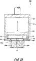
- Fig. 28 is a cross-sectional diagram showing a conventional ink jet head.
- a conventional ink jet head 500 has an ink manifold 501 forming a common ink chamber, a substrate 502, a head chip 503, and a damper member 504 provided in an ink manifold chamber 501a.
- the head chip 503 is provided with plural channels 503a as pressure chambers and a nozzle plate.
- the ink manifold 501 is formed in a hollow approximately rectangular-parallelepiped shape, and opened in one surface.
- the substrate 502 is provided so as to cover the opening of the ink manifold 501.
- the substrate 502 is provided between the ink manifold 501 and the head chip 503. Further, plural through holes 502a which communicate with the channels 503a of the head chip 503 are formed in the substrate 502.
- the ink manifold 501 and the plural channels 503a of the head chip 503 communicate with each other via the through holes 502a of the substrate 502.
- the damper member 504 is provided so as to be opposite to the substrate 502 in the opening of the ink manifold 501.
- the damper member 504 is provided close to the substrate 502 and the channels 503a of the head chip 503 so as to enhance the effect of pressure attenuation with the damper member 504. Accordingly, the flow path in a region PI between the damper member 504 and the head chip 503 under the damper member 504 is narrow.
- the flow speed is lower than that in other regions, and the bubbles easily remain.
- the conventional ink jet head has a problem that the remained bubbles enter the pressure chamber to cause reduction of the injection performance.
- the present invention has an object to provide an ink jet head capable of efficiently removing bubbles remaining in a common ink chamber and an image forming apparatus having this ink jet head.
- an ink jet head comprises a head chip having a plurality of pressure chambers, and an ink manifold having a common ink chamber that supplies ink to the head chip.
- the ink manifold has a supply port, a discharge port, an ink supply flow path, a damper member, an ink discharge flow path, and a partition wall.
- the supply port is provided with the ink.
- the discharge port discharges the ink and bubbles remaining in the ink.
- the ink supply flow path is provided in the inner space of the ink manifold.
- the ink supply flow path communicates with the supply port.
- the ink passes through the ink supply port.
- the damper member is provided in the inner space.
- the damper member is provided to face an opening of the plurality of pressure chambers on the ink manifold side.
- the ink having passed through the ink supply flow path, passes through a gap formed between the damper member and the head chip.
- the ink discharge flow path is provided in the inner space.
- the ink discharge flow path communicates with the discharge port.
- the ink and the bubbles, having passed through the gap pass through the ink discharge flow path.
- the partition wall is provided in the inner space. The partition wall regulates passage of the ink and the bubbles in the damper member on the opposite side to the gap.
- the ink manifold limits a direction in which the ink and the bubbles flow in the gap to a direction from the ink supply flow path toward the ink discharge flow path.
- an image forming apparatus has the above-described ink jet head.
- the ink jet head and the image forming apparatus having the above-described configurations, it is possible to efficiently remove the bubbles remaining in the common ink chamber.
- Fig. 1 is a schematic structural diagram showing the image forming apparatus according to the present embodiment.
- the conveyance direction of a recording medium R is a first direction X
- a direction orthogonal to the first direction X in the conveyance surface of the recording medium R is a second direction Y.
- a description will be made with a direction orthogonal to the first direction X and the second direction Y, i.e., an ink discharge direction (injection direction), as a third direction Z.
- the apparatus shown in Fig. 1 is an image forming apparatus to form an image by discharging ink droplets toward the recording medium R.
- the image forming apparatus 100 has a platen 101, two conveyance rollers 102, and 102, and plural line heads 103, 104, 105, and 106.
- the platen 101 is formed in a flat plate shape.
- the recording medium R is placed on an upper surface of the platen 101.
- the conveyance rollers 102 are rotatably provided at both ends of the platen 101 in the first direction X. Then, when the conveyance rollers 102 are driven, the platen 101 conveys the recording medium R in the first direction X.
- the line heads 103, 104, 105, and 106 are arrayed in parallel in the second direction Y, from one side in the first direction X, i.e., the upstream side in the conveyance direction of the recording medium R, to the other side in the first direction X, i.e., the downstream side in the conveyance direction of the recording medium R.
- the line heads 103, 104, 105, and 106 face the platen 101 in the third direction Z, with the recording medium R between the platen and the line heads.
- At least one ink jet head 1 to be described later is provided inside the line heads 103, 104, 105, and 106.
- the line heads 103, 104, 105, and 106 discharge e.g. cyan (C), magenta (M), yellow (Y), and black (K) ink toward the recording medium R.
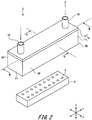
- Fig. 2 is a perspective diagram showing the ink jet head 1.
- Fig. 3 is a cross-sectional diagram along a line A-A in Fig. 2 .
- Fig. 4 is a cross-sectional diagram along a line B-B in Fig. 2 .
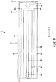
- Fig. 5 is a plan view showing the ink jet head 1 in which a cover member 12 of an ink manifold 2 is transparent.
- the ink jet head 1 has the ink manifold 2, a substrate 3, and a head chip 4.
- the ink manifold 2 is formed in a hollow approximately rectangular-parallelepiped shape, and is opened in one surface.
- the substrate 3 is provided so as to close the opening of the ink manifold 2. Note that the detailed configuration of the ink manifold 2 will be described later.
- the substrate 3 is formed with e.g. glass, ceramics, silicon, synthetic resin or the like, in an approximately flat plate shape.
- Plural through holes 3a are formed in the substrate 3.
- the through holes 3a are formed through from one surface to the other surface in the substrate 3 along the third direction Z.
- the through holes 3a communicate with a common ink chamber 10 as inner space of the ink manifold 2. Further, the through holes 3a are formed in positions facing channels 8 provided in the head chip 4 to be described later.
- the through holes 3a communicate with the channels 8.
- unshown wirings electrically connected to unshown electrodes provided on the head chip 4 to be described later, are formed on the substrate 3. Further, an unshown flexible wiring board, electrically connected to the wirings on the substrate 3, are connected to the outer edge of the substrate 3.
- the head chip 4 is bonded to the surface of the substrate 3 on the opposite side to the surface where the ink manifold 2 is bonded.
- the head chip 4 has a pressure chamber forming plate 6 and a nozzle plate 7.
- the pressure chamber forming plate 6 is formed in an approximately rectangular-parallelepiped shape.
- the pressure chamber forming plate 6 is provided with the plural channels 8 as pressure chambers.
- the plural channels 8 are formed through from one surface to the other surface in the pressure chamber forming plate 6 along the third direction Z.
- the plural channels 8 communicate with the common ink chamber 10 of the ink manifold 2 via the through holes 3a of the substrate 3.
- the plural channels 8 are arrayed along the first direction X and the second direction Y. Among the plural channels 8, plural channels 8 arrayed along the second direction Y form one channel array. This channel array is provided in plural positions along the first direction X, to form plural channel arrays.
- the channel array means a set of channels 8 (pressure chambers) which form a recording width of an image recorded with a predetermined width on the recording medium R upon one-directional relative movement between the ink jet head 1 and the recording medium R.
- the recording width is a width formed upon this conveyance of the recording medium R.
- the second direction Y as a channel array direction in the ink jet head 1 is not limited to the direction parallel to the recording width of the image formed with the recording medium R, but may be a direction obliquely crossing the recording width.
- the relative movement between the ink jet head 1 and the recording medium R is not limited to the example as shown in Fig. 1 where the ink jet head 1 is fixedly provided and the recording medium R is conveyed.
- it may be configured such that image formation is performed by scan-moving the ink jet head 1 along the width direction of the recording medium R, and the recording medium R is moved in a direction orthogonal to the scan-moving direction of the ink jet head 1 by one scan movement.
- the recording medium R is fixedly provided, image formation is performed by scan-moving the ink jet head 1 along the width direction of the recording medium R, and the ink jet head 1 is moved in a direction orthogonal to the scan-moving direction by one scan movement.
- the plural channels 8 are provided in positions facing damper members 26 and 27 provided in the ink manifold 2 to be described later, and not provided in positions not facing the damper members 26 and 27.
- the pressure chamber forming plate 6 at least a part of partition walls 9 partitioning between adjacent channels 8 in each channel array is formed with a poling processed piezoelectric device.
- An unshown driving electrode is formed on both of the surfaces of the partition wall 9. The driving electrode is connected to the wiring on the substrate 3, and voltage is applied. Then the partition wall 9 is shear-deformed by application of a driving signal at a predetermined voltage to the driving electrode. With this configuration, the capacity of the channel 8 between the pair of partition walls 9 varies so as to expand and contract. As a result, pressure for discharge is applied to the ink supplied in the channel 8.
- the nozzle plate 7 is bonded to the other surface on the opposite side to the surface in contact with the substrate 3. That is, the nozzle plate 7 is provided on the side where the ink is discharged from the channels 8 in the pressure chamber forming plate 6.
- the nozzle plate 7 is formed in an approximately flat plate shape. Plural nozzles 7a are formed in the nozzle plate 7. The nozzles 7a are provided in positions facing the channels 8 provided in the pressure chamber forming plate 6 and communicate with the channels 8. The ink in the channel 8, to which the pressure for discharge has been applied by deformation of the partition walls 9, is discharged through the channel 8 from the nozzle 7a to the outside.
- the ink manifold 2 is formed in a hollow approximately rectangular-parallelepiped shape, and is opened in one surface. Further, the ink manifold 2 has a container member 11 and the cover member 12.
- the ink manifold 2 is configured with two members, the container member 11 and the cover member 12, however, the ink manifold is not limited to this configuration. It may be configured such that the container member 11 and the cover member 12 are integrated with each other.
- the container member 11 is formed in a hollow approximately rectangular-parallelepiped shape, and is opened in one surface on the lower side in the third direction Z.
- the inner space of the container member 11 becomes the common ink chamber 10.
- the opening of the container member 11 is covered with the substrate 3.
- the cover member 12 is provided on the other surface of the container member 11 on the opposite side to the surface where the opening is formed.
- the container member 11 has a front part 21, a rear part 22, a first side wall 23, a second side wall 24, and an upper surface part 25.
- the front part 21 is provided at an end of the container member 11 in the second direction Y.
- the rear part 22 faces the front part 21, and is provided at the other end of the container member 11 in the second direction Y.
- the first side wall 23 approximately vertically continues from one end of the front part 21 in the first direction X, extends along the second direction Y, and is connected to one end of the rear part 22 in the first direction X.
- the second side wall 24 is provided to face the first side wall 23.
- the second side wall 24 approximately vertically continues from the other end of the front part 21 in the first direction X, extends along the second direction Y, and is connected to the other end of the rear part 22 in the first direction X.
- the upper surface part 25 is provided in a position facing the opening of the container member 11.
- the upper surface part 25 is connected to the front part 21, the rear part 22, the first side wall 23 and the second side wall 24.
- An ink reservoir 31, an ink supply flow path 32, a first ink discharge flow path 33, a second ink discharge flow path 34, a first partition wall 35, a second partition wall 36, a first damper chamber 37, a second damper chamber 38, and an ink discharge part 39, are provided in the inner space of the container member 11. Further, the first damper chamber 37 is provided with the first damper member 26, and the second damper chamber 38 is provided with the second damper member 27.
- the ink reservoir 31 is formed by opening the approximate center of the upper surface part 25 in the first direction X from one end in the second direction Y, along the second direction Y, to the vicinity of the other end in the second direction Y, by a predetermined length.
- the ink reservoir 31 protrudes from the upper surface part 25 along the third direction Z toward the lower side by a predetermined length.
- the ink reservoir 31 is supplied with ink from a supply port 14 to be described later. Further, in the ink reservoir 31, the ink supply flow path 32 communicates with the approximate center of the lower surface in the third direction Z, in the first direction X.
- the ink supply flow path 32 extends from the ink reservoir 31, toward the lower side in the third direction Z, to the vicinity of the opening of the container member 11. Further, as in the case of the ink reservoir 31, the ink supply flow path 32 extends from one end of the container member 11 in the second direction Y to the vicinity of the other end in the second direction Y.
- the ink supplied to the ink reservoir 31 passes through the ink supply flow path 32.
- the first damper chamber 37 is formed on one side of the ink supply flow path 32 in the first direction X
- the second damp chamber 38 is formed on the other side of the ink supply flow path 32 in the first direction X.
- the first damper chamber 37 and the second damper chamber 38 are opened on the lower side in the third direction Z.
- the openings of the first damper chamber 37 and the second damper chamber 38 face the through holes 3a of the substrate 3 bonded to the ink manifold 2 and the channels 8 of the head chip 4. Further, in the first damper chamber 37 and the second damper chamber 38, the openings are positioned in the vicinity of the opening of the ink manifold 2.
- the first damper member 26 is provided so as to cover the opening of the first damper chamber 37.
- the second damper member 27 is provided so as to cover the opening of the second damper chamber 38. Accordingly, the first damper member 26 and the second damper member 27 are provided in the vicinity of the opening of the ink manifold 2, and face the through holes 3a of the substrate 3 and the channels 8 of the head chip 4. Further, the inner spaces of the first damper chamber 37 and the second damper chamber 38 are tightly sealed with the first damper member 26 and the second damper member 27, and a gas such as air is enclosed.
- the first damper member 26 and the second damper member 27 are configured with a synthetic resin film having flexibility such as PI (polyimide), LCP (liquid crystal polymer), PET (polyethylene terephthalate), PE (polyethylene), PP (polypropylene). Further, it is preferable that the thickness of the first damper member 26 and the second damper member 27 is 10 ⁇ m or thicker and 150 ⁇ m or thinner from the viewpoint of effective development of damper effect of buffering by attenuating a pressure wave.
- PI polyimide
- LCP liquid crystal polymer
- PET polyethylene terephthalate
- PE polyethylene
- PP polypropylene
- the inner pressure of the first damper chamber 37 and the second damper chamber 38 tightly sealed with the first damper member 26 and the second damper member 27 is controlled to a predetermined pressure.
- the inner pressure of the first damper chamber 37 and the second damper chamber 38 is reduced such that, e.g., it is 50 kPa or higher and lower than atmospheric pressure under a condition of a normal temperature and one atmospheric pressure.
- the atmospheric pressure is a barometric pressure which is one atmospheric pressure upon measurement under a condition of normal temperature and one atmospheric pressure.
- first damper chamber 37 and the second damper chamber 38 in which the first damper member 26 and the second damper member 27 are provided, integrally with the container member 11, it is possible to perform positioning of the first damper member 26 and the second damper member 27 with ease. Further, it is possible to perform attachment of the first damper member 26 and the second damper member 27 with ease.
- the first ink discharge flow path 33 is provided on one side of the first damper chamber 37 opposite to the ink supply flow path 32 in the first direction X.
- the first ink discharge flow path 33 is formed between the first side wall 23 and the first damper chamber 37.
- the first ink discharge flow path 33 extends from one end to the vicinity of the other end of the container member 11 in the second direction Y. Further, the first ink discharge flow path 33 extends from the opening of the container member 11 to the vicinity of the upper surface part 25. The ink, having passed through the ink supply flow path 32 and having passed between the first damper member 26 and the substrate 3, flows through the first ink discharge flow path 33.
- the first ink discharge flow path 33 is opened from the lower side of the container member 11 in the third direction Z to the vicinity of the upper surface part 25 on the upper side in the third direction Z. Further, as shown in Fig. 4 , a first ink discharge communication path 33a is formed in an upper part of the first ink discharge flow path 33 in the third direction Z at the other end in the second direction Y. The first ink discharge communication path 33a is formed through the upper surface part 25 vertically in the third direction Z. The first ink discharge communication path 33a communicates with the ink discharge part 39 to be described later.
- the second ink discharge flow path 34 is provided on the other side of the second damper chamber 38 opposite to the ink supply flow path 32 in the first direction X.
- the second ink discharge flow path 34 is formed between the second side wall 24 and the second damper chamber 38.
- the second ink discharge flow path 34 extends from one end of the container member 11 in the second direction Y to the vicinity of the other end. Further, the second ink discharge flow path 34 extends from the opening of the container member 11 to the vicinity of the upper surface part 25. The ink, having passed through the ink supply flow path 32 and having passed between the second damper member 27 and the substrate 3, flows through the second ink discharge flow path 34.
- the second ink discharge flow path 34 is opened from the lower side of the container member 11 in the third direction Z to the vicinity of the upper surface part 25 on the upper side in the third direction Z. Further, a second ink discharge communication path 34a is formed in an upper part of the second ink discharge flow path 34 in the third direction Z at the other end in the second direction Y. The second ink discharge communication path 34a is formed through the upper surface part 25 vertically in the third direction Z. The second ink discharge communication path 34a communicates with the ink discharge part 39 to be described later.
- the ink discharge part 39 is provided at the other end of the upper surface part 25 in the second direction Y.
- the ink discharge part 39 is provided on the other side from the ink reservoir 31 in the second direction Y.
- the ink discharge part 39 is a concave part recessed from the upper surface part 25 toward the lower side in the third direction Z by a predetermined depth.
- the first ink discharge flow path 33 communicates with the ink discharge part 39 via the first ink discharge communication path 33a.
- the second ink discharge flow path 34 communicates with the ink discharge part 39 via the second ink discharge communication path 34a. The ink, having passed through the first ink discharge flow path 33 and the second ink discharge flow path 34, flows through the ink discharge part 39.
- the first partition wall 35 partitioning the first ink discharge flow path 33 from the ink supply flow path 32, is provided on the upper side of the first damper chamber 37 in the third direction Z.
- the second partition wall 36 partitioning the second ink discharge flow path 34 from the ink supply flow path 32, is provided on the upper side of the second damper chamber 38 in the third direction Z. Accordingly, the ink flows through only the lower side of the first damper chamber 37 and second damper chamber 38 in the third direction Z.
- the cover member 12 is formed in an approximate rectangular and approximate flat plate shape. Further, the cover member 12 is formed in a shape to cover the entire other surface of the container member 11. This cover member 12 is provided with the supply port 14 and a discharge port 15.
- the supply port 14 is provided at one end of the cover member 12 in the second direction Y.
- the supply port 14 is formed in a cylindrical shape.
- a cylindrical hole 14a of the supply port 14 is formed through from one surface to the other surface of the cover member 12 along the third direction Z, and communicates with the ink reservoir 31 of the container member 11. The ink is supplied from the supply port 14 toward the ink reservoir 31 of the container member 11.
- the discharge port 15 is provided at the other end of the cover member 12 in the second direction Y.
- the discharge port 15 is formed in a cylindrical shape.
- a cylindrical hole 15a of the discharge port 15 is formed through from one surface to the other surface of the cover member 12 along the third direction Z, and communicates with the ink discharge part 39 of the container member 11. The ink and bubbles stored in the ink discharge part 39 of the container member 11 are discharged from the discharge port 15.
- the common ink chamber 10 of the ink manifold 2 is supplied with the ink from the supply port 14.
- the ink supplied from the supply port 14 is stored in the ink reservoir 31.
- the ink supplied to the ink reservoir 31 passes through the ink supply flow path 32, and flows from the center of the container member 11 in the first direction X toward the opening.
- the ink having passed through the ink supply flow path 32, and having flowed to the opening of the container member 11, is divided to one side and the other side in the second direction Y . Then the ink on the one side in the first direction X passes through a gap between first damper member 26 and the substrate 3, and flows from the center in the first direction X to the one side. Further, the ink on the other side in the first direction X passes through a gap between the second damper member 27 and the substrate 3, and flows from the center in the first direction X toward the other side.
- the upper side of the first damper member 26 and the second damper member 27 in the third direction Z is partitioned with the first partition wall 35 and the second partition wall 36. Accordingly, the flow of the ink passing the upper side of the first damper member 26 and the second damper member 27 in the third direction Z is regulated with the first partition wall 35 and the second partition wall 36. Accordingly, the ink passes through only the lower side of the first damper member 26 and the second damper member 27 in the third direction Z.
- the flow of the ink in the first direction X passing through the first damper member 26 is only a flow from the center in the first direction X toward one side. Further, the flow of the ink in the first direction X passing through the second damper member 27 is only a flow from the first direction X toward the other side.
- the ink having passed through a gap between the first damper member 26 and the substrate 3 flows to the first ink discharge flow path 33. Further, the ink having passed through a gap between the second damper member 27 and the substrate 3 flows to the second ink discharge flow path 34. Note that the bubbles remaining in the lower part of the first damper member 26 in the third direction Z and in a side surface part on one side in the first direction X are pushed to the first ink discharge flow path 33 along the flow of the ink. Further, the bubbles remaining in the lower part of the second damper member 27 in the third direction Z and in a side surface part on the other side in the first direction X are pushed to the second ink discharge flow path 34 along the flow of the ink.
- the ink flowed to the first ink discharge flow path 33 flows to the ink discharge part 39 via the first ink discharge communication path 33a.
- the ink flowed to the second ink discharge flow path 34 flows to the ink discharge part 39 via the second ink discharge communication path 34a.
- the bubbles remaining in the ink are also made to pass through the first ink discharge flow path 33 and the second ink discharge flow path 34 along the flow of the ink, and pushed to the ink discharge part 39. Then the bubbles are discharged from the ink discharge part 39 via the discharge port 15 to the outside of the ink manifold 2.
- the first ink discharge flow path 33 and the second ink discharge flow path 34 are opened to the upper side in the third direction Z.
- the ink discharge part 39 is provided in the upper part of the container member 11 in the third direction Z. In this manner, the first ink discharge flow path 33, the second ink discharge flow path 34, and the ink discharge part 39 are provided in a direction where the bubbles float up by their own buoyancy. As a result, it is possible to efficiently discharge the bubbles remaining in the ink.
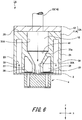
- Fig. 6 is a cross-sectional diagram showing the ink jet head according to the second embodiment.
- an ink jet head 1A according to the second embodiment differs from the ink jet head 1 according to the first embodiment. Accordingly, the ink reservoir and the ink supply flow path will be described here.
- the elements corresponding to those of the ink jet head 1 according to the first embodiment will have the same reference numerals, and overlapped explanations will be omitted.
- the ink jet head 1A has an ink manifold 2A, the substrate 3, and the head chip 4.
- An ink reservoir 31A and an ink supply flow path 32A are provided in inner space of a container member 11A of the ink manifold 2A.
- the container member 11A has the first ink discharge flow path 33, the second ink discharge flow path 34, the first partition wall 35, the second partition wall 36, the first damper chamber 37, the second damper chamber 38, and the ink discharge part 39.
- the interval in the first direction X is continuously widened in accordance with increase of distance from the ink supply flow path 32A. That is, a tapered member 31a in a tapered shape is provided in the lower part of the ink reservoir 31A in the third direction Z.
- the tapered member 31a is provided with a filter 41.
- the filter 41 removes foreign substances remaining in the ink. Further, as the ink passes through the filter 41, the bubbles remaining in the ink are finely broken. With this configuration, it is possible to suppress reduction of the injection performance upon entrance of the bubbles in the channels 8. Further, as the tapered member 31a is provided with the filter 41, it is possible to widen the effective area of the filter 41.
- Fig. 7 is a cross-sectional diagram showing the ink jet head according to the third embodiment.
- Fig. 8 is a cross-sectional diagram along a line A-A in Fig. 7 .
- Fig. 9 is a plan view in which the cover member is transparent.
- the shape of the first ink discharge flow path and the second ink discharge flow path in the ink jet head 1A according to the second embodiment is changed. Accordingly, the ink discharge flow paths will be described here.
- the elements corresponding to those of the ink jet head 1 according to the first embodiment and of the ink jet head 1A according to the second embodiment will have the same reference numerals, and overlapped explanations will be omitted.
- the ink jet head 1B has an ink manifold 2B, the substrate 3, and the head chip 4.
- the ink reservoir 31A and the ink supply flow path 32A are provided in inner space of a container member 11B of the ink manifold 2B.
- the ink reservoir 31A is provided with the filter 41.
- the container member 11B has a first ink discharge flow path 33B, a second ink discharge flow path 34B, the first partition wall 35, the second partition wall 36, the first damper chamber 37, the second damper chamber 38, and an ink discharge part 39B.
- the first ink discharge flow path 33B is inclined in a direction away from the opening of the container member 11B from one end toward the other end in the second direction Y. Accordingly, an upper surface part of the first ink discharge flow path 33B facing the head chip 44 in the third direction Z becomes away from the head chip 4 to the upper position in the third direction Z from the one end toward the other end in the second direction Y. That is, the upper surface part of the first ink discharge flow path 33B is inclined from the one end toward the ink discharge part 39B in the second direction Y.
- the configuration of the second ink discharge flow path 34B is also the same as that of the first ink discharge flow path 33B, accordingly, the explanation of the path will be omitted.
- the bubbles remaining in the ink flow, along the slopes of the first ink discharge flow path 33B and the second ink discharge flow path 34B, toward the ink discharge part 39B and the discharge port 15.
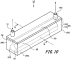
- Fig. 10 is a perspective diagram showing the ink jet head according to the fourth embodiment.
- Fig. 11 is a cross-sectional diagram along a line A-A in Fig. 10 .
- an ink jet head 1C according to the fourth embodiment is the configuration of the inner space of the container member and the configuration of the cover member. Accordingly, the container member and the cover member will be described here.
- the elements corresponding to those of the ink jet head 1 according to the first embodiment will have the same reference numerals, and overlapped explanations will be omitted.
- the ink jet head 1C has an ink manifold 2C, a substrate 3C, and a head chip 4C.
- the ink manifold 2C has a container member 11C and a cover member 12C.
- the container member 11C is formed in a hollow approximate rectangular-parallelepiped shape, and is opened in surfaces on both sides in the third direction Z.
- the container member 11C has a front part 21C, a rear part 22C, a first side wall 23C, and a second side wall 24C.
- an ink supply flow path 52, an ink discharge flow path 53, a partition wall 55, and a damper chamber 57 are formed in the inner space of the container member 11C.
- the partition wall 55 is connected to the center of the front part 21C in the first direction X on the upper side in the third direction Z.
- the partition wall 55 extends from one end to the other end in the second direction Y, and is connected to the rear part 22C.
- the damper chamber 57 is formed at a lower end of the partition wall 55 in the third direction Z. As in the case of the partition wall 55, the damper chamber 57 is continuously provided along the second direction Y from the front part 21C to the rear part 22C. The damper chamber 57 is provided with a damper member 58.
- the inner space of the container member 11C is divided with the partition wall 55 and the damper chamber 57 into one side and the other side in the first direction X.
- the one side in the first direction X in the inner space of the container member 11C becomes the ink supply flow path 52.
- the other side in the first direction X in the inner space of the container member 11C becomes the ink discharge flow path 53.
- a supply port 14C is provided on one side of the cover member 12C in the first direction X at one end in the second direction Y.
- the supply port 14C communicates with the ink supply flow path 52.
- a discharge port 15C is provided on the other side of the cover member 12C in the first direction X at the other end in the second direction Y.
- the discharge port 15C communicates with the ink discharge flow path 53.
- the ink passes from one end in the first direction X through a gap between the damper member 58 and the substrate 3C, and flows toward the other end in the first direction X.
- the damper member 58 in the center in the first direction X, and widen the area rather than the damper members 26 and 27 according to the first embodiment. Accordingly, it is possible to provide, through holes 3aC provided in the substrate 3C and the channels 8C of the head chip 4C, in the center in the first direction X. As a result, the number of channel arrays is larger than that of the ink jet head 1 according to the first embodiment.
- Fig. 12 is a plan view showing the ink jet head, in which the cover member of the ink manifold is transparent, according to the fifth embodiment.
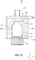
- Fig. 13 is a cross-sectional diagram along a line A-A in Fig. 12 .
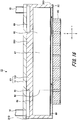
- Fig. 14 is a cross-sectional diagram along a line B-B in Fig. 12 .
- Fig. 15 is a cross-sectional diagram along a line C-C in Fig. 12 .
- Fig. 16 is a cross-sectional diagram along a line D-D in Fig. 12 .
- the difference between the ink jet head 1D according to the fifth embodiment and the ink jet head 1 according to the first embodiment is the configuration of the inner space of the ink manifold. Accordingly, the container member of the ink manifold will be described here.
- the elements corresponding to those of the ink jet head 1 according to the first embodiment will have the same reference numerals, and overlapped explanations will be omitted.
- the ink jet head 1D has an ink manifold 2D, the substrate 3C, and the head chip 4C.
- the ink manifold 2C has a container member 11D and the cover member 12. Note that the configurations of the substrate 3C and the head chip 4C are the same as those of the substrate 3C and the head chip 4C according to the fourth embodiment, accordingly, the explanations of those configurations will be omitted.
- the container member 11D is formed in an approximately rectangular-parallelepiped shape, and is opened in a surface on the lower side in the third direction Z.
- the container member 11D has a front part 21D, a rear part 22D, a first side wall 23D, a second side wall 24D, and an upper surface part 25D.
- an ink supply port 61, an ink supply flow path 62, an ink discharge flow path 63, a partition wall 65, a damper chamber 67, and an ink discharge port 69 are provided in the inner space of the container member 11D.
- the damper chamber 67 is continuously formed from one end to the other end of the container member 11D in the second direction Y.
- the damper chamber 67 is provided with a damper member 68.
- the ink supply port 61 is formed in the center of the upper surface part 25D in the first direction X at one end in the second direction Y.
- the ink supply port 61 is provided in an upper part of the damper chamber 67 in the third direction Z.
- the ink supply port 61 communicates with the supply port 14 provided in the cover member 12. Further, the ink supply port 61 also communicates with the ink supply flow path 62.
- the ink supply flow path 62 is formed at one end in the first direction X at one end in the second direction Y, in the inner space of the container member 11D.
- the ink supply flow path 62 continues from the upper side to the opening on the lower side in the third direction Z, in the inner space of the container member 11D.
- the ink supply flow path 62 is formed on one side of the damper chamber 67 in the first direction X at one end in the second direction Y.
- the ink discharge port 69 is formed in the center of the upper surface part 25D in the first direction X at the other end in the second direction Y.
- the ink discharge port 69 is provided in the upper part of the damper chamber 67 in the third direction Z.
- the ink discharge port 69 communicates with the discharge port 15 provided in the cover member 12. Further, the ink discharge port 69 also communicates with the ink discharge flow path 63.
- the ink discharge flow path 63 is formed at the other end in the first direction X at the other end in the second direction Y, in the inner space of the container member 11D.
- the ink discharge flow path 63 continues from the other side to the opening on the lower side in the third direction Z in the inner space of the container member 11D.
- the ink discharge flow path 63 is formed on the other side of the damper chamber 67 in the first direction x at the other end in the second direction Y.
- the ink supplied from the supply port 14 passes through the ink supply port 61, formed immediately beneath the supply port 14, i.e. on the lower side in the third direction Z, enters the inner space of the container member 11D. Then the ink passes through the ink supply flow path 62, and flows through a gap between the damper member 68 and the substrate 3C.
- the ink flows through the gap between the damper member 68 and the substrate 3C from one end toward the other end in the second direction Y.
- the ink having flowed to the other end in the second direction Y passes through the ink discharge flow path 63, and flows to the ink discharge port 69. Then the ink is discharged from the ink discharge port 69 to the discharge port 15.
- the position to which the ink is supplied and the position from which the ink is discharged are limited to the positions immediately beneath the supply port 14 and the discharge port 15.
- the ink jet head 1D according to the fifth embodiment by limiting the ink flow direction more than in the ink jet head according to the first embodiment, it is possible to more efficiently discharge the bubbles from the discharge port 15.
- ink jet heads 1C and 1D may be configured such that, as in the case of the ink jet heads 1A and 1B according to the second and third embodiments, a filter is provided between the supply port and the ink supply flow path.
- Fig. 17 is a plan view showing the ink jet head, in which the cover member of the ink manifold is transparent, according to the sixth embodiment of the present invention.
- Fig. 18 is a cross-sectional diagram along a line A-A in Fig. 17 .
- Fig. 19 is a cross-sectional diagram along a line B-B in Fig. 17 .
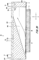
- Fig. 20 is a cross-sectional diagram along a line C-C in Fig. 17 .
- Fig. 21 is a cross-sectional diagram along a line D-D in Fig. 17 .
- the flow path to supply ink to the common ink chamber is limited to one end in the second direction Y. Accordingly, the container member of the ink manifold will be described here.
- the elements corresponding to those of the ink jet head 1 according to the first embodiment and the ink jet head 1B according to the third embodiment will have the same reference numerals, and overlapped explanations will be omitted.
- the ink jet head 1 E has an ink manifold 2E, the substrate 3, and the head chip 4.
- An ink reservoir 71, an ink supply flow path 72, and a partition wall 75 are provided in the inner space of a container member 11E of the ink manifold 2E.
- the ink reservoir 71 is provided with the filter 41.
- the ink reservoir 71 is formed at one end of an upper surface part 25E in the second direction Y. Further, the ink reservoir 71 is formed in the center of the upper surface part 25E in the first direction X.
- the ink reservoir 71 communicates with the supply port 14 provided in the cover member 12. Further, the ink reservoir 71 also communicates with the ink supply flow path 72.
- the ink supply flow path 72 communicates with the ink reservoir 71 at one end in the second direction Y, and is formed in the inner space of the container member 11E to the opening on the lower side in the third direction Z. Further, as shown in Fig. 19 and Fig. 21 , the ink reservoir 71 and the ink supply flow path 72 are formed only at one end of the container member 11E in the second direction Y.
- the container member 11E has a first ink discharge flow path 33E, a second ink discharge flow path 34E, the first damper chamber 37, the second damper chamber 38, and an ink discharge part 39E.
- the first ink discharge flow path 33E, the second ink discharge flow path 34E, the first damper chamber 37, the second damper chamber 38, and the ink discharge part 39E have the same configurations as those of the first ink discharge flow path 33B, the second ink discharge flow path 34E, the first damper chamber 37 the second damper chamber 38, and the ink discharge part 39B according to the third embodiment, accordingly, the explanations of the configurations will be omitted.
- the partition wall 75 partitions upper parts of the first damper chamber 37 and a second damper chamber 78 in the third direction Z. Further, the partition wall 75 also partitions the first damper chamber 37 from the second damper chamber 38, from an intermediate part to the other end of the container member 11E in the second direction Y.
- the ink supplied from the supply port 14 is supplied via the ink reservoir 71 and the ink supply flow path 72, from one end of the container member 11E in the second direction Y to the inner space. Then, the ink having passed through the ink supply flow path 72 passes through a gap between the first damper member 26 or the second damper member 27 and the substrate 3, flows toward both sides in the first direction X, and flows from one side to the other side in the second direction Y. The ink passes through the first ink discharge flow path 33E and the second ink discharge flow path 34E, and is discharged from the ink discharge part 39E to the discharge port 15.
- Fig. 22 is a perspective diagram showing the ink jet head, in which the cover member of the ink manifold is transparent, according to the seventh embodiment.
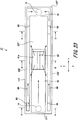
- Fig. 23 is a plan view showing the ink jet head in which the cover member of the ink manifold is transparent.
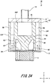
- Fig. 24 is a cross-sectional diagram along a line A-A in Fig. 23 .
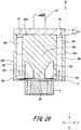
- Fig. 25 is a cross-sectional diagram along a line B-B in Fig. 23 .
- Fig. 26 is a cross-sectional diagram along a line C-C in Fig. 23 .
- the ink jet head 1F has an ink manifold 2F, the substrate 3, and the head chip 4.
- a container member 11F of the ink manifold 2F is formed in an approximately rectangular-parallelepiped shape, and is opened in a surface on the lower side in the third direction Z.
- the container member 11F has a front part 21F, a rear part 22F, a first side wall 23F, a second side wall 24F, and an upper surface part 25F.
- an ink reservoir 81, an ink supply flow path 82, a first ink discharge flow path 83, a second ink discharge flow path 84, a third ink discharge flow path 85, and a fourth ink discharge flow path 86 are provided in the inner space of the container member 11F.
- a first damper chamber 87, a second damper chamber 88, a first common discharge flow path 89, a second common discharge flow path 90, an ink discharge part 91, and a partition wall 92 are provided in the inner space of the container member 11F.
- the ink reservoir 81 is formed in the center of the upper surface part 25F in the first direction X.
- the ink reservoir 81 extends from one end to an intermediate part of the upper surface part 25F in the second direction Y.
- the ink reservoir 81 is a concave part recessed from the upper surface part 25F toward the lower side in the third direction Z by a predetermined length.
- the supply port 14 communicates with the ink reservoir 81.
- an ink supply port 81a is opened in an intermediate part of the container member 11F in the second direction Y.
- the ink supply port 81a is formed by opening a lower surface of the ink reservoir 81 in the third direction Z.
- the ink supply flow path 82 communicates with the ink supply port 81a.
- the ink supply port 81a is provided with a filter 93. As the filter 93 has the same configuration as that of the filter 41 according to the second embodiment, the explanation of the filter will be omitted.
- the ink supply flow path 82 is continuously formed to the opening on the lower side in the third direction Z, in the center in the first direction X, in an intermediate part of the container member 11F in the second direction Y.
- the first damper chamber 87 is provided on one side of the ink supply flow path 82 in the first direction X.
- the second damper chamber 88 is provided on the other side of the ink supply flow path 82 in the first direction X.
- the first damper chamber 87 is provided with a first damper member 94.
- the second damper chamber 88 is provided with a second damper member 95.
- the configurations of the first damper chamber 87, the second damper chamber 88, the first damper member 94, and the second damper member 95 are the same as those of the first damper chamber 37, the second damper chamber 38, the first damper member 26 and the second damper member 27 according to the first embodiment, the explanations of the configurations will be omitted.
- the first ink discharge flow path 83 and the second ink discharge flow path 84 are provided at one end of the container member 11F in the second direction Y.
- the first ink discharge flow path 83 is formed on one side from the first damper chamber 87 in the first direction X.
- the second ink discharge flow path 84 is formed on the other side from the second damper chamber 88 in the first direction X.
- the first ink discharge flow path 83 and the second ink discharge flow path 84 are formed through from the opening of the container member 11F on the lower side to the upper surface part 25F on the upper side, in the third direction Z.
- the third ink discharge flow path 85 and the fourth ink discharge flow path 86 are provided at the other end of the container member 11F in the second direction Y.
- the third ink discharge flow path 85 is formed on one side from the first damper chamber 87 in the first direction X.
- the fourth ink discharge flow path 86 is formed on the other side from the second damper chamber 88 in the first direction X.
- the third ink discharge flow path 85 and the fourth ink discharge flow path 86 are formed through from the opening of the container member 11F on the lower side to the upper surface part 25F on the upper side, in the third direction Z.
- the first common discharge flow path 89 and the second common discharge flow path 90 are provided on both sides of the upper surface part 25F in the first direction X.
- the first common discharge flow path 89 is formed at one end of the upper surface part 25F in the first direction X.
- the first common discharge flow path 89 is a groove which continues from one end to the other end of the upper surface part 25F in the second direction Y.
- the first ink discharge flow path 83 communicates with one end of the first common discharge flow path 89 in the second direction Y.
- the third ink discharge flow path 85 communicates with the other end of the first common discharge flow path 89 in the second direction Y.
- the second common discharge flow path 90 is formed at the other end of the upper surface part 25F in the first direction X.
- the second common discharge flow path 90 is a groove which continues from one end to the other end of the upper surface part 25F in the second direction Y.
- the second ink discharge flow path 84 communicates with one end of the second common discharge flow path 90 in the second direction Y.
- the fourth ink discharge flow path 86 communicates with the other end of the second common discharge flow path 90 in the second direction Y.
- the ink discharge part 91 is provided at the other end of the upper surface part 25F in the second direction Y.
- the ink discharge part 91 is a concave part formed in an intermediate part of the upper surface part 25F in the first direction X, and recessed toward the lower side in the third direction Z by a predetermined length.
- the first common discharge flow path 89 and the second common discharge flow path 90 communicate with the ink discharge part 91. Further, the discharge port 15 communicates with the ink discharge part 91.
- the upper side of the first damper chamber 87 and the second damper chamber 88 in the third direction Z is partitioned with the partition wall 92. Further, as shown in Fig. 26 , the partition wall 92 partitions the first damper chamber 87 from the second damper chamber 88 at the other end in the second direction Y.
- the ink jet head 1F As shown in Fig. 22 and Fig. 23 , the ink jet head 1F according to the seventh embodiment, the ink supplied from the supply port 14 is first stored in the ink reservoir 81.
- the ink flows through the ink reservoir 81 from one end toward the intermediate part in the second direction Y, and as shown in Fig. 25 , the ink flows from the ink supply port 81a to the ink supply flow path 82.
- the ink passes through the ink supply flow path 82, and flows to the opening of the container member 11 on the lower side in the third direction Z.
- the ink having passed through the ink supply flow path 82 passes through a gap between the first damper member 94 and the second damper member 95 and substrate 3, and flows toward the four corners of the container member 11.
- the ink having flowed to the four corners of the container member 11 passes through the first ink discharge flow path 83, the second ink discharge flow path 84, the third ink discharge flow path 85 or the fourth ink discharge flow path 86, and flows to the first common discharge flow path 89 or the second common discharge flow path 90.
- the ink flows via the first common discharge flow path 89 or the second common discharge flow path 90 to the ink discharge part 91, and is discharged from the ink discharge part 91 to the discharge port 15.
- the ink is introduced from the center of the container member 11F, and the ink is caused to flow toward the four corners of the container member 11F.
- the ink discharge flow paths 83, 84, 85 and 86 are provided at the four corners of the container member 11F, it is possible to efficiently discharge bubbles, which easily stay at the corners, to the ink discharge flow paths 83, 84, 85 and 86.
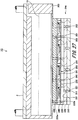
- Fig. 27 is a cross-sectional diagram showing another example of the head chip.
- an ink jet head 1G has the ink manifold 2, a holding member 203 covering the opening of the ink manifold 2, and a head chip 204.
- the holding member 203 is formed in an approximate flat plate shape, and has a through hole 203a which communicates with the common ink chamber 10 as the inner space of the ink manifold 2.
- the head chip 204 is bonded to the holding member 203.
- the head chip 204 has a nozzle plate 210, an intermediate plate 220, a pressure chamber forming plate 230, a drive plate 240, and a wiring board 250. Further, the head chip 204 is formed by laminating the nozzle plate 210, the intermediate plate 220, the pressure chamber forming plate 230, the drive plate 240, and the wiring board 250, in this order, from the ink discharge surface side.
- Plural nozzles 211 are formed in the nozzle plate 210.
- the nozzle 211 is formed through from one surface to the other surface of the nozzle plate 210.
- the nozzle 211 discharges ink supplied from the common ink chamber 10 to the outside.
- the nozzle 211 communicates with a pressure chamber 231 formed in the pressure chamber forming plate 230 via the intermediate plate 220 laminated on the nozzle plate 210.
- the intermediate plate 220 is provided between the nozzle plate 210 and the pressure chamber forming plate 230.
- the intermediate plate 220 is provided with a first communication hole 221 for communication between the nozzles 211 and the pressure chamber 231 provided in the pressure chamber forming plate 230.
- the first communication hole 221 is provided in a position corresponding to the nozzle 211 of the nozzle plate 210, and is formed through from one surface to the other surface of the intermediate plate 220.
- the pressure chamber forming plate 230 has plural pressure chambers (channels) 231 and a vibration plate 232.
- the pressure chamber 231 is formed through from one surface to the other surface of the pressure chamber forming plate 230. With this pressure chamber 231, discharge pressure is applied to the ink discharged from the nozzle 211. Further, the pressure chamber 231 is provided in a position corresponding to the nozzle 211 of the nozzle plate 210 and the first communication hole 221 of the intermediate plate 220.
- the vibration plate 232 is provided so as to cover the opening of the pressure chamber 231 on the opposite side to the intermediate plate 220.
- the vibration plate 232 is provided with a second communication hole 232a which communicates with the pressure chamber 231.
- the drive plate 240 is provided on one surface of the vibration plate 232 on the opposite side to one surface on the pressure chamber 231 side.
- the drive plate 240 has space 241 and a third communication hole 242 which communicates with the second communication hole 232a.
- the space 241 is provided in a position facing the pressure chamber 231, with the vibration plate 232 between the space and the pressure chamber.
- An actuator 260 is accommodated in the space 241.
- the actuator 260 has a piezoelectric device 261 and unshown two electrodes.
- the piezoelectric device 261 is provided between the two electrodes, and laminated on one surface of the vibration plate 232.
- the piezoelectric device 261 is provided by pressure chamber 231 (by channel).
- the piezoelectric device 261 is formed with a material which is deformed by application of voltage, e.g., ferroelectric material such as lead zirconate titanate (PZT). Further, the electrode in the piezoelectric device 261 on the opposite side to the vibration plate 232 is connected with the wiring layer 251 provided on the wiring board 250.
- ferroelectric material such as lead zirconate titanate (PZT).
- the wiring board 250 has a wiring layer 251 and a silicon layer 252 where the wiring layer 251 is formed on one surface.
- the wiring layer 251 is connected to the electrodes of the actuator 260. Further, the outer edge of the wiring layer 251 is connected to an unshown flexible wiring board. Further, the silicon layer 252 is provided on one surface of the wiring layer 251 on the opposite side to the drive plate 240. The silicon layer 252 is bonded to the holding member 203.
- the wiring board 250 is provided with a fourth communication hole 253 formed through the wiring layer 251 and the silicon layer 252.
- the fourth communication hole 253 communicates with the common ink chamber 10 via the third communication hole 242 of the drive plate 240 and the through hole 203a of the holding member 203.
- conveyance roller ; 103, 104, 105, 106 ... line head; 203 ... holding member; 203a ... through hole; 204 ... head chip; 210 ... nozzle plate; 211 ... nozzle; 220 ... intermediate plate; 230 ... pressure chamber forming plate; 231 ... pressure chamber; 232 ... vibration plate; 240 ... drive plate; 241 ... space; 250 ... wiring board; 251 ... wiring layer; 252 ... silicon layer; 260 ... actuator; 261 ... piezoelectric device.
Landscapes
- Particle Formation And Scattering Control In Inkjet Printers (AREA)
- Ink Jet (AREA)
Abstract
Description
- The present invention relates to an ink jet head in which a common ink chamber is provided with a damper, and to an image forming apparatus having the ink jet head.
- Conventionally, high-resolution ink jet head using MEMS (Micro Electro Mechanical Systems) technology has been developed. The conventional ink jet head has plural channels to discharge ink. The ink jet head has a pressure chamber, an actuator to provide discharge pressure to ink supplied to the pressure chamber, and a nozzle plate with a nozzle hole to discharge the ink in the pressure chamber, by channel. Further, the ink jet head is provided with a common ink chamber to supply the ink to the pressure chamber.
- Note that in the ink jet head, in some cases, the injection performance becomes nonuniform due to a pressure wave caused in the pressure chamber by driving of the actuator. The pressure wave caused by the driving in the pressure chamber is propagated to the pressure chambers of the other channels, communicated with each other, with the common ink chamber, to cause variation in the injection characteristic of the pressure wave-propagated pressure chamber, i.e., so-called crosstalk.
- Conventionally, as a technique of reducing the influence among the pressure chambers due to crosstalk, e.g., a technique disclosed in Patent Literature 1 is known. Patent Literature 1 discloses a technique of providing a damper member in a common ink chamber. In the technique disclosed in this Patent Literature 1, the damper member having a flexible film is provided oppositely to an ink entrance of the pressure chamber, in the common ink chamber.
-
Fig. 28 is a cross-sectional diagram showing a conventional ink jet head. - As shown in
Fig. 28 , a conventionalink jet head 500 has anink manifold 501 forming a common ink chamber, asubstrate 502, ahead chip 503, and adamper member 504 provided in anink manifold chamber 501a. Thehead chip 503 is provided withplural channels 503a as pressure chambers and a nozzle plate. Theink manifold 501 is formed in a hollow approximately rectangular-parallelepiped shape, and opened in one surface. - The
substrate 502 is provided so as to cover the opening of theink manifold 501. Thesubstrate 502 is provided between theink manifold 501 and thehead chip 503.
Further, plural throughholes 502a which communicate with thechannels 503a of thehead chip 503 are formed in thesubstrate 502. Theink manifold 501 and theplural channels 503a of thehead chip 503 communicate with each other via the throughholes 502a of thesubstrate 502. Thedamper member 504 is provided so as to be opposite to thesubstrate 502 in the opening of theink manifold 501. - PTL 1: Japanese Patent Application Laid-Open No.
2015-223737 - However, as shown in
Fig. 28 , thedamper member 504 is provided close to thesubstrate 502 and thechannels 503a of thehead chip 503 so as to enhance the effect of pressure attenuation with thedamper member 504. Accordingly, the flow path in a region PI between thedamper member 504 and thehead chip 503 under thedamper member 504 is narrow. - Further, two ink flow paths divided with the
damper member 504 join together again in this region P1. As a result, when remaining bubbles are mixed in the common ink chamber, the bubbles may easily remain in the region PI among thedamper member 504, thesubstrate 502 and thehead chip 503 under thedamper member 504. - Further, in a region P2 in a side surface part of the
damper member 504 and in a region P3 at a corner of thedamper member 504 and in the chamber of theink manifold 501, the flow speed is lower than that in other regions, and the bubbles easily remain. In this manner, as the bubbles remain around the damper member, the conventional ink jet head has a problem that the remained bubbles enter the pressure chamber to cause reduction of the injection performance. - In view of the above-described conventional problem, the present invention has an object to provide an ink jet head capable of efficiently removing bubbles remaining in a common ink chamber and an image forming apparatus having this ink jet head.
- To solve the above-described problem, and to attain the object of the present invention, an ink jet head according to the present invention comprises a head chip having a plurality of pressure chambers, and an ink manifold having a common ink chamber that supplies ink to the head chip. The ink manifold has a supply port, a discharge port, an ink supply flow path, a damper member, an ink discharge flow path, and a partition wall. The supply port is provided with the ink. The discharge port discharges the ink and bubbles remaining in the ink. The ink supply flow path is provided in the inner space of the ink manifold. The ink supply flow path communicates with the supply port. The ink passes through the ink supply port. The damper member is provided in the inner space. The damper member is provided to face an opening of the plurality of pressure chambers on the ink manifold side. The ink, having passed through the ink supply flow path, passes through a gap formed between the damper member and the head chip. The ink discharge flow path is provided in the inner space. The ink discharge flow path communicates with the discharge port. The ink and the bubbles, having passed through the gap, pass through the ink discharge flow path. The partition wall is provided in the inner space. The partition wall regulates passage of the ink and the bubbles in the damper member on the opposite side to the gap. The ink manifold limits a direction in which the ink and the bubbles flow in the gap to a direction from the ink supply flow path toward the ink discharge flow path.
- Further, an image forming apparatus according to the present invention has the above-described ink jet head.
- According to the ink jet head and the image forming apparatus having the above-described configurations, it is possible to efficiently remove the bubbles remaining in the common ink chamber.
-
-
Fig. 1 is a schematic structural diagram showing an image forming apparatus according to a first embodiment of the present invention; -
Fig. 2 is a perspective diagram showing an ink jet head according to the first embodiment of the present invention; -
Fig. 3 is a cross-sectional diagram along a line A-A inFig. 2 ; -
Fig. 4 is a cross-sectional diagram along a line B-B inFig. 2 ; -
Fig. 5 is a plan view showing the ink jet head according to the first embodiment of the present invention, in which a cover member of an ink manifold is transparent; -
Fig. 6 is a cross-sectional diagram showing the ink jet head according to a second embodiment of the present invention; -
Fig. 7 is a cross-sectional diagram showing the ink jet head according to a third embodiment of the present invention; -
Fig. 8 is a cross-sectional diagram along a line A-A inFig. 7 ; -
Fig. 9 is a plan view of the ink jet head according to the third embodiment of the present invention, in which the cover member of the ink manifold is transparent; -
Fig. 10 is a perspective diagram showing the ink jet head according to a fourth embodiment of the present invention; -
Fig. 11 is a cross-sectional diagram along a line A-A inFig. 10 ; -
Fig. 12 is a plan view showing the ink jet head according to a fifth embodiment of the present invention, in which the cover member of the ink manifold is transparent; -
Fig. 13 is a cross-sectional diagram along a line A-A inFig. 12 ; -
Fig. 14 is a cross-sectional diagram along a line B-B inFig. 12 ; -
Fig. 15 is a cross-sectional diagram along a line C-C inFig. 12 ; -
Fig. 16 is a cross-sectional diagram along a line D-D inFig. 12 ; -
Fig. 17 is a plan view showing the ink jet head according to a sixth embodiment of the present invention, in which the cover member of the ink manifold is transparent; -
Fig. 18 is a cross-sectional diagram along a line A-A inFig. 17 ; -
Fig. 19 is a cross-sectional diagram along a line B-B inFig. 17 ; -
Fig. 20 is a cross-sectional diagram along a line C-C inFig. 17 ; -
Fig. 21 is a cross-sectional diagram along a line D-D inFig. 17 ; -
Fig. 22 is a perspective diagram showing the ink jet head according to a seventh embodiment of the present invention, in which the cover member of the ink manifold is transparent; -
Fig. 23 is a plan view showing the ink jet head according to the seventh embodiment of the present invention, in which the cover member of the ink manifold is transparent; -
Fig. 24 is a cross-sectional diagram along a line A-A inFig. 23 ; -
Fig. 25 is a cross-sectional diagram along a line B-B inFig. 23 ; -
Fig. 26 is a cross-sectional diagram along a line C-C inFig. 23 ; -
Fig. 27 is a cross-sectional diagram showing another example of a head chip of the ink jet head according to the present invention; and -
Fig. 28 is a cross-sectional diagram showing a conventional ink jet head. - Hereinbelow, embodiments for implementation of an ink jet head and an image forming apparatus having the ink jet head according to the present invention will be described with reference to
Figs. 1 to 27 . Note that in the respective figures, corresponding elements have the same reference numerals. Further, the present invention is not limited to the following embodiments. - First, the configuration of the image forming apparatus according to a first embodiment (hereinbelow, referred to as "present embodiment") of the present invention will be described with reference to
Fig. 1 . -
Fig. 1 is a schematic structural diagram showing the image forming apparatus according to the present embodiment. - Note that in the following explanation, the conveyance direction of a recording medium R is a first direction X, and a direction orthogonal to the first direction X in the conveyance surface of the recording medium R is a second direction Y. Then a description will be made with a direction orthogonal to the first direction X and the second direction Y, i.e., an ink discharge direction (injection direction), as a third direction Z.
- The apparatus shown in
Fig. 1 is an image forming apparatus to form an image by discharging ink droplets toward the recording medium R. As shown inFig. 1 , theimage forming apparatus 100 has aplaten 101, twoconveyance rollers - The
platen 101 is formed in a flat plate shape. The recording medium R is placed on an upper surface of theplaten 101. Theconveyance rollers 102 are rotatably provided at both ends of theplaten 101 in the first direction X. Then, when theconveyance rollers 102 are driven, theplaten 101 conveys the recording medium R in the first direction X. - The line heads 103, 104, 105, and 106 are arrayed in parallel in the second direction Y, from one side in the first direction X, i.e., the upstream side in the conveyance direction of the recording medium R, to the other side in the first direction X, i.e., the downstream side in the conveyance direction of the recording medium R. The line heads 103, 104, 105, and 106 face the
platen 101 in the third direction Z, with the recording medium R between the platen and the line heads. - Further, at least one ink jet head 1 to be described later (see
Fig. 2 ) is provided inside the line heads 103, 104, 105, and 106. The line heads 103, 104, 105, and 106 discharge e.g. cyan (C), magenta (M), yellow (Y), and black (K) ink toward the recording medium R. - Next, the configuration of the ink jet head 1 will be described with reference to
Figs. 2 to 5 . -
Fig. 2 is a perspective diagram showing the ink jet head 1.Fig. 3 is a cross-sectional diagram along a line A-A inFig. 2 .Fig. 4 is a cross-sectional diagram along a line B-B inFig. 2 .Fig. 5 is a plan view showing the ink jet head 1 in which acover member 12 of anink manifold 2 is transparent. - As shown in
Fig. 2 andFig. 3 , the ink jet head 1 has theink manifold 2, asubstrate 3, and ahead chip 4. Theink manifold 2 is formed in a hollow approximately rectangular-parallelepiped shape, and is opened in one surface. As shown inFig. 3 andFig. 4 , thesubstrate 3 is provided so as to close the opening of theink manifold 2. Note that the detailed configuration of theink manifold 2 will be described later. - The
substrate 3 is formed with e.g. glass, ceramics, silicon, synthetic resin or the like, in an approximately flat plate shape. Plural throughholes 3a are formed in thesubstrate 3. The throughholes 3a are formed through from one surface to the other surface in thesubstrate 3 along the third direction Z. The throughholes 3a communicate with acommon ink chamber 10 as inner space of theink manifold 2. Further, the throughholes 3a are formed inpositions facing channels 8 provided in thehead chip 4 to be described later. The throughholes 3a communicate with thechannels 8. - Further, unshown wirings, electrically connected to unshown electrodes provided on the
head chip 4 to be described later, are formed on thesubstrate 3. Further, an unshown flexible wiring board, electrically connected to the wirings on thesubstrate 3, are connected to the outer edge of thesubstrate 3. - The
head chip 4 is bonded to the surface of thesubstrate 3 on the opposite side to the surface where theink manifold 2 is bonded. Thehead chip 4 has a pressurechamber forming plate 6 and anozzle plate 7. - The pressure
chamber forming plate 6 is formed in an approximately rectangular-parallelepiped shape. The pressurechamber forming plate 6 is provided with theplural channels 8 as pressure chambers. Theplural channels 8 are formed through from one surface to the other surface in the pressurechamber forming plate 6 along the third direction Z. Theplural channels 8 communicate with thecommon ink chamber 10 of theink manifold 2 via the throughholes 3a of thesubstrate 3. - The
plural channels 8 are arrayed along the first direction X and the second direction Y. Among theplural channels 8,plural channels 8 arrayed along the second direction Y form one channel array. This channel array is provided in plural positions along the first direction X, to form plural channel arrays. - Note that the channel array (pressure chamber array) means a set of channels 8 (pressure chambers) which form a recording width of an image recorded with a predetermined width on the recording medium R upon one-directional relative movement between the ink jet head 1 and the recording medium R.
- When, e.g. the ink jet head 1 is fixedly provided with respect to the recording medium R and image formation is performed while the recording medium R is being conveyed in the first direction X as shown in
Fig. 1 , the recording width is a width formed upon this conveyance of the recording medium R. The second direction Y as a channel array direction in the ink jet head 1 is not limited to the direction parallel to the recording width of the image formed with the recording medium R, but may be a direction obliquely crossing the recording width. - Further, the relative movement between the ink jet head 1 and the recording medium R is not limited to the example as shown in
Fig. 1 where the ink jet head 1 is fixedly provided and the recording medium R is conveyed. For example, it may be configured such that image formation is performed by scan-moving the ink jet head 1 along the width direction of the recording medium R, and the recording medium R is moved in a direction orthogonal to the scan-moving direction of the ink jet head 1 by one scan movement. Otherwise, it may be configured such that the recording medium R is fixedly provided, image formation is performed by scan-moving the ink jet head 1 along the width direction of the recording medium R, and the ink jet head 1 is moved in a direction orthogonal to the scan-moving direction by one scan movement. - Further, as shown in
Fig. 2 , theplural channels 8 are provided in positions facingdamper members ink manifold 2 to be described later, and not provided in positions not facing thedamper members - Further, in the pressure
chamber forming plate 6, at least a part ofpartition walls 9 partitioning betweenadjacent channels 8 in each channel array is formed with a poling processed piezoelectric device. An unshown driving electrode is formed on both of the surfaces of thepartition wall 9. The driving electrode is connected to the wiring on thesubstrate 3, and voltage is applied. Then thepartition wall 9 is shear-deformed by application of a driving signal at a predetermined voltage to the driving electrode. With this configuration, the capacity of thechannel 8 between the pair ofpartition walls 9 varies so as to expand and contract. As a result, pressure for discharge is applied to the ink supplied in thechannel 8. - Further, in the pressure
chamber forming plate 6, thenozzle plate 7 is bonded to the other surface on the opposite side to the surface in contact with thesubstrate 3. That is, thenozzle plate 7 is provided on the side where the ink is discharged from thechannels 8 in the pressurechamber forming plate 6. - The
nozzle plate 7 is formed in an approximately flat plate shape.Plural nozzles 7a are formed in thenozzle plate 7. Thenozzles 7a are provided in positions facing thechannels 8 provided in the pressurechamber forming plate 6 and communicate with thechannels 8. The ink in thechannel 8, to which the pressure for discharge has been applied by deformation of thepartition walls 9, is discharged through thechannel 8 from thenozzle 7a to the outside. - Next, the configuration of the
ink manifold 2 will be described. - As shown in
Fig. 2 to Fig. 5 , theink manifold 2 is formed in a hollow approximately rectangular-parallelepiped shape, and is opened in one surface. Further, theink manifold 2 has acontainer member 11 and thecover member 12. - Note that in the present example, the
ink manifold 2 is configured with two members, thecontainer member 11 and thecover member 12, however, the ink manifold is not limited to this configuration. It may be configured such that thecontainer member 11 and thecover member 12 are integrated with each other. - The
container member 11 is formed in a hollow approximately rectangular-parallelepiped shape, and is opened in one surface on the lower side in the third direction Z. The inner space of thecontainer member 11 becomes thecommon ink chamber 10. As described above, the opening of thecontainer member 11 is covered with thesubstrate 3. Further, thecover member 12 is provided on the other surface of thecontainer member 11 on the opposite side to the surface where the opening is formed. - Further, the
container member 11 has afront part 21, arear part 22, afirst side wall 23, asecond side wall 24, and anupper surface part 25. Thefront part 21 is provided at an end of thecontainer member 11 in the second direction Y. Therear part 22 faces thefront part 21, and is provided at the other end of thecontainer member 11 in the second direction Y. - The
first side wall 23 approximately vertically continues from one end of thefront part 21 in the first direction X, extends along the second direction Y, and is connected to one end of therear part 22 in the first direction X. Thesecond side wall 24 is provided to face thefirst side wall 23. Thesecond side wall 24 approximately vertically continues from the other end of thefront part 21 in the first direction X, extends along the second direction Y, and is connected to the other end of therear part 22 in the first direction X. - The
upper surface part 25 is provided in a position facing the opening of thecontainer member 11. Theupper surface part 25 is connected to thefront part 21, therear part 22, thefirst side wall 23 and thesecond side wall 24. - An
ink reservoir 31, an inksupply flow path 32, a first inkdischarge flow path 33, a second inkdischarge flow path 34, afirst partition wall 35, asecond partition wall 36, afirst damper chamber 37, asecond damper chamber 38, and anink discharge part 39, are provided in the inner space of thecontainer member 11. Further, thefirst damper chamber 37 is provided with thefirst damper member 26, and thesecond damper chamber 38 is provided with thesecond damper member 27. - As shown in
Fig. 3 andFig. 5 , theink reservoir 31 is formed by opening the approximate center of theupper surface part 25 in the first direction X from one end in the second direction Y, along the second direction Y, to the vicinity of the other end in the second direction Y, by a predetermined length. Theink reservoir 31 protrudes from theupper surface part 25 along the third direction Z toward the lower side by a predetermined length. Theink reservoir 31 is supplied with ink from asupply port 14 to be described later. Further, in theink reservoir 31, the inksupply flow path 32 communicates with the approximate center of the lower surface in the third direction Z, in the first direction X. - The ink
supply flow path 32 extends from theink reservoir 31, toward the lower side in the third direction Z, to the vicinity of the opening of thecontainer member 11. Further, as in the case of theink reservoir 31, the inksupply flow path 32 extends from one end of thecontainer member 11 in the second direction Y to the vicinity of the other end in the second direction Y. The ink supplied to theink reservoir 31 passes through the inksupply flow path 32. Further, thefirst damper chamber 37 is formed on one side of the inksupply flow path 32 in the first direction X, and the seconddamp chamber 38 is formed on the other side of the inksupply flow path 32 in the first direction X. - The
first damper chamber 37 and thesecond damper chamber 38 are opened on the lower side in the third direction Z. The openings of thefirst damper chamber 37 and thesecond damper chamber 38 face the throughholes 3a of thesubstrate 3 bonded to theink manifold 2 and thechannels 8 of thehead chip 4. Further, in thefirst damper chamber 37 and thesecond damper chamber 38, the openings are positioned in the vicinity of the opening of theink manifold 2. - The
first damper member 26 is provided so as to cover the opening of thefirst damper chamber 37. Thesecond damper member 27 is provided so as to cover the opening of thesecond damper chamber 38. Accordingly, thefirst damper member 26 and thesecond damper member 27 are provided in the vicinity of the opening of theink manifold 2, and face the throughholes 3a of thesubstrate 3 and thechannels 8 of thehead chip 4. Further, the inner spaces of thefirst damper chamber 37 and thesecond damper chamber 38 are tightly sealed with thefirst damper member 26 and thesecond damper member 27, and a gas such as air is enclosed. - The
first damper member 26 and thesecond damper member 27 are configured with a synthetic resin film having flexibility such as PI (polyimide), LCP (liquid crystal polymer), PET (polyethylene terephthalate), PE (polyethylene), PP (polypropylene). Further, it is preferable that the thickness of thefirst damper member 26 and thesecond damper member 27 is 10 µm or thicker and 150 µm or thinner from the viewpoint of effective development of damper effect of buffering by attenuating a pressure wave. - Further, the inner pressure of the
first damper chamber 37 and thesecond damper chamber 38 tightly sealed with thefirst damper member 26 and thesecond damper member 27 is controlled to a predetermined pressure. The inner pressure of thefirst damper chamber 37 and thesecond damper chamber 38 is reduced such that, e.g., it is 50 kPa or higher and lower than atmospheric pressure under a condition of a normal temperature and one atmospheric pressure. With this configuration, it is possible to suppress narrowing of the flow path, formed between thefirst damper member 26 and thesecond damper member 27 and thesubstrate 3, with the damper members, and to attain an excellent damper effect. Note that the atmospheric pressure is a barometric pressure which is one atmospheric pressure upon measurement under a condition of normal temperature and one atmospheric pressure. - In this manner, by forming the
first damper chamber 37 and thesecond damper chamber 38, in which thefirst damper member 26 and thesecond damper member 27 are provided, integrally with thecontainer member 11, it is possible to perform positioning of thefirst damper member 26 and thesecond damper member 27 with ease. Further, it is possible to perform attachment of thefirst damper member 26 and thesecond damper member 27 with ease. - Further, the first ink
discharge flow path 33 is provided on one side of thefirst damper chamber 37 opposite to the inksupply flow path 32 in the first direction X. The first inkdischarge flow path 33 is formed between thefirst side wall 23 and thefirst damper chamber 37. As shown inFig. 4 andFig. 5 , the first inkdischarge flow path 33 extends from one end to the vicinity of the other end of thecontainer member 11 in the second direction Y. Further, the first inkdischarge flow path 33 extends from the opening of thecontainer member 11 to the vicinity of theupper surface part 25. The ink, having passed through the inksupply flow path 32 and having passed between thefirst damper member 26 and thesubstrate 3, flows through the first inkdischarge flow path 33. - As shown in
Fig. 3 , the first inkdischarge flow path 33 is opened from the lower side of thecontainer member 11 in the third direction Z to the vicinity of theupper surface part 25 on the upper side in the third direction Z. Further, as shown inFig. 4 , a first inkdischarge communication path 33a is formed in an upper part of the first inkdischarge flow path 33 in the third direction Z at the other end in the second direction Y. The first inkdischarge communication path 33a is formed through theupper surface part 25 vertically in the third direction Z. The first inkdischarge communication path 33a communicates with theink discharge part 39 to be described later. - Further, as shown in
Fig. 3 andFig. 5 , the second inkdischarge flow path 34 is provided on the other side of thesecond damper chamber 38 opposite to the inksupply flow path 32 in the first direction X. The second inkdischarge flow path 34 is formed between thesecond side wall 24 and thesecond damper chamber 38. The second inkdischarge flow path 34 extends from one end of thecontainer member 11 in the second direction Y to the vicinity of the other end. Further, the second inkdischarge flow path 34 extends from the opening of thecontainer member 11 to the vicinity of theupper surface part 25. The ink, having passed through the inksupply flow path 32 and having passed between thesecond damper member 27 and thesubstrate 3, flows through the second inkdischarge flow path 34. - As shown in
Fig. 3 , the second inkdischarge flow path 34 is opened from the lower side of thecontainer member 11 in the third direction Z to the vicinity of theupper surface part 25 on the upper side in the third direction Z. Further, a second inkdischarge communication path 34a is formed in an upper part of the second inkdischarge flow path 34 in the third direction Z at the other end in the second direction Y. The second inkdischarge communication path 34a is formed through theupper surface part 25 vertically in the third direction Z. The second inkdischarge communication path 34a communicates with theink discharge part 39 to be described later. - Further, the
ink discharge part 39 is provided at the other end of theupper surface part 25 in the second direction Y. In theupper surface part 25, theink discharge part 39 is provided on the other side from theink reservoir 31 in the second direction Y. Theink discharge part 39 is a concave part recessed from theupper surface part 25 toward the lower side in the third direction Z by a predetermined depth. The first inkdischarge flow path 33 communicates with theink discharge part 39 via the first inkdischarge communication path 33a. Further, the second inkdischarge flow path 34 communicates with theink discharge part 39 via the second inkdischarge communication path 34a. The ink, having passed through the first inkdischarge flow path 33 and the second inkdischarge flow path 34, flows through theink discharge part 39. - Further, as shown in
Fig. 3 , thefirst partition wall 35, partitioning the first inkdischarge flow path 33 from the inksupply flow path 32, is provided on the upper side of thefirst damper chamber 37 in the third direction Z. Further, thesecond partition wall 36, partitioning the second inkdischarge flow path 34 from the inksupply flow path 32, is provided on the upper side of thesecond damper chamber 38 in the third direction Z. Accordingly, the ink flows through only the lower side of thefirst damper chamber 37 andsecond damper chamber 38 in the third direction Z. - The
cover member 12 is formed in an approximate rectangular and approximate flat plate shape. Further, thecover member 12 is formed in a shape to cover the entire other surface of thecontainer member 11. Thiscover member 12 is provided with thesupply port 14 and adischarge port 15. - The
supply port 14 is provided at one end of thecover member 12 in the second direction Y. Thesupply port 14 is formed in a cylindrical shape. Acylindrical hole 14a of thesupply port 14 is formed through from one surface to the other surface of thecover member 12 along the third direction Z, and communicates with theink reservoir 31 of thecontainer member 11. The ink is supplied from thesupply port 14 toward theink reservoir 31 of thecontainer member 11. - Further, the
discharge port 15 is provided at the other end of thecover member 12 in the second direction Y. Thedischarge port 15 is formed in a cylindrical shape. Acylindrical hole 15a of thedischarge port 15 is formed through from one surface to the other surface of thecover member 12 along the third direction Z, and communicates with theink discharge part 39 of thecontainer member 11. The ink and bubbles stored in theink discharge part 39 of thecontainer member 11 are discharged from thedischarge port 15. - Next, the flow of the ink and the bubbles remaining in the ink, in the ink jet head 1 having the above-described configuration, will be described.
- As shown in
Fig. 2 ,Fig. 4 andFig. 5 , thecommon ink chamber 10 of theink manifold 2 is supplied with the ink from thesupply port 14. First, the ink supplied from thesupply port 14 is stored in theink reservoir 31. Then as shown inFig. 3 , the ink supplied to theink reservoir 31 passes through the inksupply flow path 32, and flows from the center of thecontainer member 11 in the first direction X toward the opening. - The ink, having passed through the ink
supply flow path 32, and having flowed to the opening of thecontainer member 11, is divided to one side and the other side in the second direction Y. Then the ink on the one side in the first direction X passes through a gap betweenfirst damper member 26 and thesubstrate 3, and flows from the center in the first direction X to the one side. Further, the ink on the other side in the first direction X passes through a gap between thesecond damper member 27 and thesubstrate 3, and flows from the center in the first direction X toward the other side. - Note that the upper side of the
first damper member 26 and thesecond damper member 27 in the third direction Z is partitioned with thefirst partition wall 35 and thesecond partition wall 36. Accordingly, the flow of the ink passing the upper side of thefirst damper member 26 and thesecond damper member 27 in the third direction Z is regulated with thefirst partition wall 35 and thesecond partition wall 36. Accordingly, the ink passes through only the lower side of thefirst damper member 26 and thesecond damper member 27 in the third direction Z. - Then the flow of the ink in the first direction X passing through the
first damper member 26 is only a flow from the center in the first direction X toward one side. Further, the flow of the ink in the first direction X passing through thesecond damper member 27 is only a flow from the first direction X toward the other side. - With this configuration, it is possible to push the bubbles remaining between the
first damper member 26 and thesecond damper member 27 and thesubstrate 3 from the center in the first direction X to one side or the other side in the first direction X with the flow of the ink. As a result, it is possible to prevent the bubbles remaining between thefirst damper member 26 and thesecond damper member 27 and thesubstrate 3 from entering thechannels 8 to lower the injection performance. - Further, the ink having passed through a gap between the
first damper member 26 and thesubstrate 3 flows to the first inkdischarge flow path 33. Further, the ink having passed through a gap between thesecond damper member 27 and thesubstrate 3 flows to the second inkdischarge flow path 34. Note that the bubbles remaining in the lower part of thefirst damper member 26 in the third direction Z and in a side surface part on one side in the first direction X are pushed to the first inkdischarge flow path 33 along the flow of the ink. Further, the bubbles remaining in the lower part of thesecond damper member 27 in the third direction Z and in a side surface part on the other side in the first direction X are pushed to the second inkdischarge flow path 34 along the flow of the ink. - Further, as shown in
Fig. 5 , the ink flowed to the first inkdischarge flow path 33 flows to theink discharge part 39 via the first inkdischarge communication path 33a. Then, the ink flowed to the second inkdischarge flow path 34 flows to theink discharge part 39 via the second inkdischarge communication path 34a. Accordingly, the bubbles remaining in the ink are also made to pass through the first inkdischarge flow path 33 and the second inkdischarge flow path 34 along the flow of the ink, and pushed to theink discharge part 39. Then the bubbles are discharged from theink discharge part 39 via thedischarge port 15 to the outside of theink manifold 2. - In this manner, by limiting the flow of the ink supplied into the
common ink chamber 10 as inner space of theink manifold 2 such that it is directed to a predetermined direction, it is possible to efficiently remove the bubbles remaining in the ink. - Further, as shown in
Fig. 3 , the first inkdischarge flow path 33 and the second inkdischarge flow path 34 are opened to the upper side in the third direction Z. Theink discharge part 39 is provided in the upper part of thecontainer member 11 in the third direction Z. In this manner, the first inkdischarge flow path 33, the second inkdischarge flow path 34, and theink discharge part 39 are provided in a direction where the bubbles float up by their own buoyancy. As a result, it is possible to efficiently discharge the bubbles remaining in the ink. - Next, the ink jet head according to a second embodiment of the present invention will be described with reference to
Fig. 6 . -
Fig. 6 is a cross-sectional diagram showing the ink jet head according to the second embodiment. - The difference between an
ink jet head 1A according to the second embodiment and the ink jet head 1 according to the first embodiment is the configurations of the ink reservoir and the ink supply flow path. Accordingly, the ink reservoir and the ink supply flow path will be described here. The elements corresponding to those of the ink jet head 1 according to the first embodiment will have the same reference numerals, and overlapped explanations will be omitted. - As shown in
Fig. 6 , theink jet head 1A has anink manifold 2A, thesubstrate 3, and thehead chip 4. Anink reservoir 31A and an inksupply flow path 32A are provided in inner space of acontainer member 11A of theink manifold 2A. Further, thecontainer member 11A has the first inkdischarge flow path 33, the second inkdischarge flow path 34, thefirst partition wall 35, thesecond partition wall 36, thefirst damper chamber 37, thesecond damper chamber 38, and theink discharge part 39. - In a lower part of the
ink reservoir 31A in the third direction Z, the interval in the first direction X is continuously widened in accordance with increase of distance from the inksupply flow path 32A. That is, atapered member 31a in a tapered shape is provided in the lower part of theink reservoir 31A in the third direction Z. - The tapered
member 31a is provided with afilter 41. Thefilter 41 removes foreign substances remaining in the ink. Further, as the ink passes through thefilter 41, the bubbles remaining in the ink are finely broken. With this configuration, it is possible to suppress reduction of the injection performance upon entrance of the bubbles in thechannels 8. Further, as thetapered member 31a is provided with thefilter 41, it is possible to widen the effective area of thefilter 41. - As other constituent elements are the same as those of the ink jet head 1 according to the above-described first embodiment, the explanations of those elements will be omitted. It is possible with the
ink jet head 1A having this configuration to obtain the same operations and effects as those obtained with the ink jet head 1 according to the above-described first embodiment. - Next, the ink jet head according to a third embodiment of the present invention will be described with reference to
Fig. 7 to Fig. 9 . -
Fig. 7 is a cross-sectional diagram showing the ink jet head according to the third embodiment.Fig. 8 is a cross-sectional diagram along a line A-A inFig. 7 .Fig. 9 is a plan view in which the cover member is transparent. - As an
ink jet head 1B according to the third embodiment, the shape of the first ink discharge flow path and the second ink discharge flow path in theink jet head 1A according to the second embodiment is changed. Accordingly, the ink discharge flow paths will be described here. The elements corresponding to those of the ink jet head 1 according to the first embodiment and of theink jet head 1A according to the second embodiment will have the same reference numerals, and overlapped explanations will be omitted. - As shown in
Fig. 7 to Fig. 9 , theink jet head 1B has anink manifold 2B, thesubstrate 3, and thehead chip 4. Theink reservoir 31A and the inksupply flow path 32A are provided in inner space of acontainer member 11B of theink manifold 2B. Theink reservoir 31A is provided with thefilter 41. - Further, the
container member 11B has a first inkdischarge flow path 33B, a second inkdischarge flow path 34B, thefirst partition wall 35, thesecond partition wall 36, thefirst damper chamber 37, thesecond damper chamber 38, and anink discharge part 39B. - As shown in
Fig. 8 , the first inkdischarge flow path 33B is inclined in a direction away from the opening of thecontainer member 11B from one end toward the other end in the second direction Y. Accordingly, an upper surface part of the first inkdischarge flow path 33B facing the head chip 44 in the third direction Z becomes away from thehead chip 4 to the upper position in the third direction Z from the one end toward the other end in the second direction Y. That is, the upper surface part of the first inkdischarge flow path 33B is inclined from the one end toward theink discharge part 39B in the second direction Y. Note that the configuration of the second inkdischarge flow path 34B is also the same as that of the first inkdischarge flow path 33B, accordingly, the explanation of the path will be omitted. - According to the
ink jet head 1B according to the third embodiment, the bubbles remaining in the ink flow, along the slopes of the first inkdischarge flow path 33B and the second inkdischarge flow path 34B, toward theink discharge part 39B and thedischarge port 15. As a result, it is possible to also discharge the bubbles remaining at one end away from theink discharge part 39B and thedischarge port 15 in the second direction Y, efficiently, from theink discharge part 39B and thedischarge port 15. - As other constituent elements are the same as those of the ink jet head 1 according to the first embodiment and the
ink jet head 1A according to the second embodiment described above, the explanations of those elements will be omitted. It is possible with theink jet head 1B having this configuration to obtain the same operations and effects as those obtained with the ink jet head 1 according to the first embodiment and theink jet head 1A according to the second embodiment described above. - Next, the ink jet head according to a fourth embodiment of the present invention will be described with reference to
Fig. 10 andFig. 11 . -
Fig. 10 is a perspective diagram showing the ink jet head according to the fourth embodiment.Fig. 11 is a cross-sectional diagram along a line A-A inFig. 10 . - The difference between an
ink jet head 1C according to the fourth embodiment and the ink jet head 1 according to the first embodiment is the configuration of the inner space of the container member and the configuration of the cover member. Accordingly, the container member and the cover member will be described here. The elements corresponding to those of the ink jet head 1 according to the first embodiment will have the same reference numerals, and overlapped explanations will be omitted. - As shown in
Fig. 10 andFig. 11 , theink jet head 1C has an ink manifold 2C, asubstrate 3C, and ahead chip 4C. The ink manifold 2C has a container member 11C and acover member 12C. - The container member 11C is formed in a hollow approximate rectangular-parallelepiped shape, and is opened in surfaces on both sides in the third direction Z. The container member 11C has a
front part 21C, arear part 22C, afirst side wall 23C, and asecond side wall 24C. - Further, an ink
supply flow path 52, an inkdischarge flow path 53, apartition wall 55, and adamper chamber 57 are formed in the inner space of the container member 11C. Thepartition wall 55 is connected to the center of thefront part 21C in the first direction X on the upper side in the third direction Z. Thepartition wall 55 extends from one end to the other end in the second direction Y, and is connected to therear part 22C. - The
damper chamber 57 is formed at a lower end of thepartition wall 55 in the third direction Z. As in the case of thepartition wall 55, thedamper chamber 57 is continuously provided along the second direction Y from thefront part 21C to therear part 22C. Thedamper chamber 57 is provided with adamper member 58. - Accordingly, the inner space of the container member 11C is divided with the
partition wall 55 and thedamper chamber 57 into one side and the other side in the first direction X. As shown inFig. 11 , the one side in the first direction X in the inner space of the container member 11C becomes the inksupply flow path 52. Further, the other side in the first direction X in the inner space of the container member 11C becomes the inkdischarge flow path 53. - Further, as shown in
Fig. 10 , asupply port 14C is provided on one side of thecover member 12C in the first direction X at one end in the second direction Y. Thesupply port 14C communicates with the inksupply flow path 52. Further, adischarge port 15C is provided on the other side of thecover member 12C in the first direction X at the other end in the second direction Y. Thedischarge port 15C communicates with the inkdischarge flow path 53. - As shown in
Fig. 11 , in theink jet head 1C according to the fourth embodiment, the ink passes from one end in the first direction X through a gap between thedamper member 58 and thesubstrate 3C, and flows toward the other end in the first direction X. - Further, according to the
ink jet head 1C according to the fourth embodiment, it is possible to provide thedamper member 58 in the center in the first direction X, and widen the area rather than thedamper members substrate 3C and thechannels 8C of thehead chip 4C, in the center in the first direction X. As a result, the number of channel arrays is larger than that of the ink jet head 1 according to the first embodiment. - As other constituent elements are the same as those of the ink jet head 1 according to the above-described first embodiment, the explanations of those elements will be omitted. It is possible with the
ink jet head 1C having this configuration to obtain the same operations and effects as those obtained with the ink jet head 1 according to the above-described first embodiment. - Next, the ink jet head according to a fifth embodiment of the present invention will be described with reference to
Fig. 12 to Fig. 16 . -
Fig. 12 is a plan view showing the ink jet head, in which the cover member of the ink manifold is transparent, according to the fifth embodiment.Fig. 13 is a cross-sectional diagram along a line A-A inFig. 12 .Fig. 14 is a cross-sectional diagram along a line B-B inFig. 12 .Fig. 15 is a cross-sectional diagram along a line C-C inFig. 12 .Fig. 16 is a cross-sectional diagram along a line D-D inFig. 12 . - The difference between the
ink jet head 1D according to the fifth embodiment and the ink jet head 1 according to the first embodiment is the configuration of the inner space of the ink manifold. Accordingly, the container member of the ink manifold will be described here. The elements corresponding to those of the ink jet head 1 according to the first embodiment will have the same reference numerals, and overlapped explanations will be omitted. - As shown in
Fig. 12 to Fig. 16 , theink jet head 1D has anink manifold 2D, thesubstrate 3C, and thehead chip 4C. The ink manifold 2C has acontainer member 11D and thecover member 12. Note that the configurations of thesubstrate 3C and thehead chip 4C are the same as those of thesubstrate 3C and thehead chip 4C according to the fourth embodiment, accordingly, the explanations of those configurations will be omitted. - The
container member 11D is formed in an approximately rectangular-parallelepiped shape, and is opened in a surface on the lower side in the third direction Z. Thecontainer member 11D has afront part 21D, arear part 22D, afirst side wall 23D, asecond side wall 24D, and anupper surface part 25D. - Further, an
ink supply port 61, an inksupply flow path 62, an inkdischarge flow path 63, apartition wall 65, adamper chamber 67, and anink discharge port 69, are provided in the inner space of thecontainer member 11D. As shown inFig. 16 , as in the case of thedamper chamber 57 according to the fourth embodiment, thedamper chamber 67 is continuously formed from one end to the other end of thecontainer member 11D in the second direction Y. Thedamper chamber 67 is provided with adamper member 68. - As shown in
Fig. 12 andFig. 13 , theink supply port 61 is formed in the center of theupper surface part 25D in the first direction X at one end in the second direction Y. Theink supply port 61 is provided in an upper part of thedamper chamber 67 in the third direction Z. Theink supply port 61 communicates with thesupply port 14 provided in thecover member 12. Further, theink supply port 61 also communicates with the inksupply flow path 62. - The ink
supply flow path 62 is formed at one end in the first direction X at one end in the second direction Y, in the inner space of thecontainer member 11D. The inksupply flow path 62 continues from the upper side to the opening on the lower side in the third direction Z, in the inner space of thecontainer member 11D. The inksupply flow path 62 is formed on one side of thedamper chamber 67 in the first direction X at one end in the second direction Y. - As shown in
Fig. 12 andFig. 14 , theink discharge port 69 is formed in the center of theupper surface part 25D in the first direction X at the other end in the second direction Y. Theink discharge port 69 is provided in the upper part of thedamper chamber 67 in the third direction Z. Theink discharge port 69 communicates with thedischarge port 15 provided in thecover member 12. Further, theink discharge port 69 also communicates with the inkdischarge flow path 63. - The ink
discharge flow path 63 is formed at the other end in the first direction X at the other end in the second direction Y, in the inner space of thecontainer member 11D. The inkdischarge flow path 63 continues from the other side to the opening on the lower side in the third direction Z in the inner space of thecontainer member 11D. The inkdischarge flow path 63 is formed on the other side of thedamper chamber 67 in the first direction x at the other end in the second direction Y. - As shown in
Fig. 15 , only thedamper chamber 67 and thedamper member 68 are provided in the intermediate part of the inner space of thecontainer member 11D in the second direction Y. The both sides of thedamper chamber 67 in the first direction X and the upper side in the third direction Z are covered with thepartition wall 65. - In the ink jet head ID according to the fifth embodiment, the ink supplied from the
supply port 14 passes through theink supply port 61, formed immediately beneath thesupply port 14, i.e. on the lower side in the third direction Z, enters the inner space of thecontainer member 11D. Then the ink passes through the inksupply flow path 62, and flows through a gap between thedamper member 68 and thesubstrate 3C. - Further, as shown in
Fig. 16 , the ink flows through the gap between thedamper member 68 and thesubstrate 3C from one end toward the other end in the second direction Y. The ink having flowed to the other end in the second direction Y passes through the inkdischarge flow path 63, and flows to theink discharge port 69. Then the ink is discharged from theink discharge port 69 to thedischarge port 15. - In the
ink jet head 1D according to the fifth embodiment, the position to which the ink is supplied and the position from which the ink is discharged are limited to the positions immediately beneath thesupply port 14 and thedischarge port 15. With this configuration, in theink jet head 1D according to the fifth embodiment, by limiting the ink flow direction more than in the ink jet head according to the first embodiment, it is possible to more efficiently discharge the bubbles from thedischarge port 15. - As other constituent elements are the same as those of the ink jet head 1 according to the above-described first embodiment, the explanations of those elements will be omitted. It is possible with the
ink jet head 1D having this configuration to obtain the same operations and effects as those obtained with the ink jet head 1 according to the above-described first embodiment. - Further, in the ink jet heads 1C and 1D according to the above-described fourth and fifth embodiments, it may be configured such that, as in the case of the ink jet heads 1A and 1B according to the second and third embodiments, a filter is provided between the supply port and the ink supply flow path.
- Next, the ink jet head according to a sixth embodiment of the present invention will be described with reference to
Fig. 17 to Fig. 21 . -
Fig. 17 is a plan view showing the ink jet head, in which the cover member of the ink manifold is transparent, according to the sixth embodiment of the present invention.Fig. 18 is a cross-sectional diagram along a line A-A inFig. 17 .Fig. 19 is a cross-sectional diagram along a line B-B inFig. 17 .Fig. 20 is a cross-sectional diagram along a line C-C inFig. 17 .Fig. 21 is a cross-sectional diagram along a line D-D inFig. 17 . - As an
ink jet head 1E according to the sixth embodiment, in theink jet head 1B according to the third embodiment, the flow path to supply ink to the common ink chamber is limited to one end in the second direction Y. Accordingly, the container member of the ink manifold will be described here. The elements corresponding to those of the ink jet head 1 according to the first embodiment and theink jet head 1B according to the third embodiment will have the same reference numerals, and overlapped explanations will be omitted. - As shown in
Fig. 17 to Fig. 21 , theink jet head 1 E has anink manifold 2E, thesubstrate 3, and thehead chip 4. Anink reservoir 71, an inksupply flow path 72, and apartition wall 75 are provided in the inner space of acontainer member 11E of theink manifold 2E. Theink reservoir 71 is provided with thefilter 41. - As shown in
Fig. 17 andFig. 18 , theink reservoir 71 is formed at one end of anupper surface part 25E in the second direction Y. Further, theink reservoir 71 is formed in the center of theupper surface part 25E in the first direction X. Theink reservoir 71 communicates with thesupply port 14 provided in thecover member 12. Further, theink reservoir 71 also communicates with the inksupply flow path 72. - Further, the ink
supply flow path 72 communicates with theink reservoir 71 at one end in the second direction Y, and is formed in the inner space of thecontainer member 11E to the opening on the lower side in the third direction Z. Further, as shown inFig. 19 andFig. 21 , theink reservoir 71 and the inksupply flow path 72 are formed only at one end of thecontainer member 11E in the second direction Y. - Further, the
container member 11E has a first inkdischarge flow path 33E, a second inkdischarge flow path 34E, thefirst damper chamber 37, thesecond damper chamber 38, and anink discharge part 39E. Note that as shown inFig. 20 , the first inkdischarge flow path 33E, the second inkdischarge flow path 34E, thefirst damper chamber 37, thesecond damper chamber 38, and theink discharge part 39E have the same configurations as those of the first inkdischarge flow path 33B, the second inkdischarge flow path 34E, thefirst damper chamber 37 thesecond damper chamber 38, and theink discharge part 39B according to the third embodiment, accordingly, the explanations of the configurations will be omitted. - As shown in
Fig. 19 andFig. 21 , thepartition wall 75 partitions upper parts of thefirst damper chamber 37 and a second damper chamber 78 in the third direction Z. Further, thepartition wall 75 also partitions thefirst damper chamber 37 from thesecond damper chamber 38, from an intermediate part to the other end of thecontainer member 11E in the second direction Y. - With this configuration, the ink supplied from the
supply port 14 is supplied via theink reservoir 71 and the inksupply flow path 72, from one end of thecontainer member 11E in the second direction Y to the inner space. Then, the ink having passed through the inksupply flow path 72 passes through a gap between thefirst damper member 26 or thesecond damper member 27 and thesubstrate 3, flows toward both sides in the first direction X, and flows from one side to the other side in the second direction Y. The ink passes through the first inkdischarge flow path 33E and the second inkdischarge flow path 34E, and is discharged from theink discharge part 39E to thedischarge port 15. - As other constituent elements are the same as those of the ink jet head 1 according to the above-described first embodiment, the explanations of those elements will be omitted. It is possible with the
ink jet head 1 E having this configuration to obtain the same operations and effects as those obtained with the ink jet head 1 according to the above-described first embodiment and theink jet head 1E according to the third embodiment. - Next, the ink jet head according to a seventh embodiment of the present invention will be described with reference to
Fig. 22 to Fig. 26 . -
Fig. 22 is a perspective diagram showing the ink jet head, in which the cover member of the ink manifold is transparent, according to the seventh embodiment.Fig. 23 is a plan view showing the ink jet head in which the cover member of the ink manifold is transparent.Fig. 24 is a cross-sectional diagram along a line A-A inFig. 23 .Fig. 25 is a cross-sectional diagram along a line B-B inFig. 23 .Fig. 26 is a cross-sectional diagram along a line C-C inFig. 23 . - The difference between an
ink jet head 1F according to the seventh embodiment and the ink jet head 1 according to the first embodiment is that the position to supply ink and the position to discharge the ink. Accordingly, the container member will be described here. The elements corresponding to those of the ink jet head 1 according to the first embodiment will have the same reference numerals, and overlapped explanations will be omitted. - As shown in
Fig. 22 to Fig. 26 , theink jet head 1F has anink manifold 2F, thesubstrate 3, and thehead chip 4. Acontainer member 11F of theink manifold 2F is formed in an approximately rectangular-parallelepiped shape, and is opened in a surface on the lower side in the third direction Z. Thecontainer member 11F has afront part 21F, arear part 22F, afirst side wall 23F, asecond side wall 24F, and anupper surface part 25F. - Further, an
ink reservoir 81, an inksupply flow path 82, a first inkdischarge flow path 83, a second inkdischarge flow path 84, a third inkdischarge flow path 85, and a fourth inkdischarge flow path 86, are provided in the inner space of thecontainer member 11F. Further, afirst damper chamber 87, asecond damper chamber 88, a first commondischarge flow path 89, a second commondischarge flow path 90, anink discharge part 91, and apartition wall 92, are provided in the inner space of thecontainer member 11F. - As shown in
Fig. 22 ,Fig. 23 andFig. 24 , theink reservoir 81 is formed in the center of theupper surface part 25F in the first direction X. Theink reservoir 81 extends from one end to an intermediate part of theupper surface part 25F in the second direction Y. Theink reservoir 81 is a concave part recessed from theupper surface part 25F toward the lower side in the third direction Z by a predetermined length. Thesupply port 14 communicates with theink reservoir 81. - As shown in
Fig. 22 andFig. 25 , in theink reservoir 81, anink supply port 81a is opened in an intermediate part of thecontainer member 11F in the second direction Y. Theink supply port 81a is formed by opening a lower surface of theink reservoir 81 in the third direction Z. The inksupply flow path 82 communicates with theink supply port 81a. Further, theink supply port 81a is provided with afilter 93. As thefilter 93 has the same configuration as that of thefilter 41 according to the second embodiment, the explanation of the filter will be omitted. - The ink
supply flow path 82 is continuously formed to the opening on the lower side in the third direction Z, in the center in the first direction X, in an intermediate part of thecontainer member 11F in the second direction Y. Thefirst damper chamber 87 is provided on one side of the inksupply flow path 82 in the first direction X. Thesecond damper chamber 88 is provided on the other side of the inksupply flow path 82 in the first direction X. Thefirst damper chamber 87 is provided with afirst damper member 94. Thesecond damper chamber 88 is provided with asecond damper member 95. - The configurations of the
first damper chamber 87, thesecond damper chamber 88, thefirst damper member 94, and thesecond damper member 95 are the same as those of thefirst damper chamber 37, thesecond damper chamber 38, thefirst damper member 26 and thesecond damper member 27 according to the first embodiment, the explanations of the configurations will be omitted. - As shown in
Fig. 22 ,Fig. 23 andFig. 24 , the first inkdischarge flow path 83 and the second inkdischarge flow path 84 are provided at one end of thecontainer member 11F in the second direction Y. The first inkdischarge flow path 83 is formed on one side from thefirst damper chamber 87 in the first direction X. The second inkdischarge flow path 84 is formed on the other side from thesecond damper chamber 88 in the first direction X. The first inkdischarge flow path 83 and the second inkdischarge flow path 84 are formed through from the opening of thecontainer member 11F on the lower side to theupper surface part 25F on the upper side, in the third direction Z. - Further, as shown in
Fig. 22 ,Fig. 23 andFig. 26 , the third inkdischarge flow path 85 and the fourth inkdischarge flow path 86 are provided at the other end of thecontainer member 11F in the second direction Y. The third inkdischarge flow path 85 is formed on one side from thefirst damper chamber 87 in the first direction X. The fourth inkdischarge flow path 86 is formed on the other side from thesecond damper chamber 88 in the first direction X. The third inkdischarge flow path 85 and the fourth inkdischarge flow path 86 are formed through from the opening of thecontainer member 11F on the lower side to theupper surface part 25F on the upper side, in the third direction Z. - As shown in
Fig. 22 to Fig. 26 , the first commondischarge flow path 89 and the second commondischarge flow path 90 are provided on both sides of theupper surface part 25F in the first direction X. The first commondischarge flow path 89 is formed at one end of theupper surface part 25F in the first direction X. The first commondischarge flow path 89 is a groove which continues from one end to the other end of theupper surface part 25F in the second direction Y. The first inkdischarge flow path 83 communicates with one end of the first commondischarge flow path 89 in the second direction Y. The third inkdischarge flow path 85 communicates with the other end of the first commondischarge flow path 89 in the second direction Y. - The second common
discharge flow path 90 is formed at the other end of theupper surface part 25F in the first direction X. The second commondischarge flow path 90 is a groove which continues from one end to the other end of theupper surface part 25F in the second direction Y. The second inkdischarge flow path 84 communicates with one end of the second commondischarge flow path 90 in the second direction Y. The fourth inkdischarge flow path 86 communicates with the other end of the second commondischarge flow path 90 in the second direction Y. - As shown in
Fig. 22 andFig. 23 , theink discharge part 91 is provided at the other end of theupper surface part 25F in the second direction Y. Theink discharge part 91 is a concave part formed in an intermediate part of theupper surface part 25F in the first direction X, and recessed toward the lower side in the third direction Z by a predetermined length. The first commondischarge flow path 89 and the second commondischarge flow path 90 communicate with theink discharge part 91. Further, thedischarge port 15 communicates with theink discharge part 91. - As shown in
Fig. 24 andFig. 25 , the upper side of thefirst damper chamber 87 and thesecond damper chamber 88 in the third direction Z is partitioned with thepartition wall 92. Further, as shown inFig. 26 , thepartition wall 92 partitions thefirst damper chamber 87 from thesecond damper chamber 88 at the other end in the second direction Y. - As shown in
Fig. 22 andFig. 23 , theink jet head 1F according to the seventh embodiment, the ink supplied from thesupply port 14 is first stored in theink reservoir 81. The ink flows through theink reservoir 81 from one end toward the intermediate part in the second direction Y, and as shown inFig. 25 , the ink flows from theink supply port 81a to the inksupply flow path 82. The ink passes through the inksupply flow path 82, and flows to the opening of thecontainer member 11 on the lower side in the third direction Z. - The ink having passed through the ink
supply flow path 82 passes through a gap between thefirst damper member 94 and thesecond damper member 95 andsubstrate 3, and flows toward the four corners of thecontainer member 11. The ink having flowed to the four corners of thecontainer member 11 passes through the first inkdischarge flow path 83, the second inkdischarge flow path 84, the third inkdischarge flow path 85 or the fourth inkdischarge flow path 86, and flows to the first commondischarge flow path 89 or the second commondischarge flow path 90. Next, the ink flows via the first commondischarge flow path 89 or the second commondischarge flow path 90 to theink discharge part 91, and is discharged from theink discharge part 91 to thedischarge port 15. - In this manner, in the
ink jet head 1F according to the seventh embodiment, the ink is introduced from the center of thecontainer member 11F, and the ink is caused to flow toward the four corners of thecontainer member 11F. With this configuration, it is possible to remove unevenness of the ink at one end and the other end of thecontainer member 11F in the second direction Y. Further, as the inkdischarge flow paths container member 11F, it is possible to efficiently discharge bubbles, which easily stay at the corners, to the inkdischarge flow paths - As other constituent elements are the same as those of the ink jet head 1 according to the above-described first embodiment, the explanations of those elements will be omitted. It is possible with the
ink jet head 1F having this configuration to obtain the same operations and effects as those obtained with the ink jet head 1 according to the above-described first embodiment. - Next, another example of the head chip in the ink jet head according to the present invention will be described with reference to
Fig. 27 . -
Fig. 27 is a cross-sectional diagram showing another example of the head chip. - As shown in
Fig. 27 , anink jet head 1G has theink manifold 2, a holdingmember 203 covering the opening of theink manifold 2, and ahead chip 204. The holdingmember 203 is formed in an approximate flat plate shape, and has a throughhole 203a which communicates with thecommon ink chamber 10 as the inner space of theink manifold 2. - The
head chip 204 is bonded to the holdingmember 203. Thehead chip 204 has anozzle plate 210, anintermediate plate 220, a pressurechamber forming plate 230, adrive plate 240, and awiring board 250. Further, thehead chip 204 is formed by laminating thenozzle plate 210, theintermediate plate 220, the pressurechamber forming plate 230, thedrive plate 240, and thewiring board 250, in this order, from the ink discharge surface side. -
Plural nozzles 211 are formed in thenozzle plate 210. Thenozzle 211 is formed through from one surface to the other surface of thenozzle plate 210. Thenozzle 211 discharges ink supplied from thecommon ink chamber 10 to the outside. Thenozzle 211 communicates with apressure chamber 231 formed in the pressurechamber forming plate 230 via theintermediate plate 220 laminated on thenozzle plate 210. - The
intermediate plate 220 is provided between thenozzle plate 210 and the pressurechamber forming plate 230. Theintermediate plate 220 is provided with afirst communication hole 221 for communication between thenozzles 211 and thepressure chamber 231 provided in the pressurechamber forming plate 230. Thefirst communication hole 221 is provided in a position corresponding to thenozzle 211 of thenozzle plate 210, and is formed through from one surface to the other surface of theintermediate plate 220. - The pressure
chamber forming plate 230 has plural pressure chambers (channels) 231 and avibration plate 232. Thepressure chamber 231 is formed through from one surface to the other surface of the pressurechamber forming plate 230. With thispressure chamber 231, discharge pressure is applied to the ink discharged from thenozzle 211. Further, thepressure chamber 231 is provided in a position corresponding to thenozzle 211 of thenozzle plate 210 and thefirst communication hole 221 of theintermediate plate 220. - The
vibration plate 232 is provided so as to cover the opening of thepressure chamber 231 on the opposite side to theintermediate plate 220. Thevibration plate 232 is provided with asecond communication hole 232a which communicates with thepressure chamber 231. Thedrive plate 240 is provided on one surface of thevibration plate 232 on the opposite side to one surface on thepressure chamber 231 side. - The
drive plate 240 hasspace 241 and athird communication hole 242 which communicates with thesecond communication hole 232a. Thespace 241 is provided in a position facing thepressure chamber 231, with thevibration plate 232 between the space and the pressure chamber. Anactuator 260 is accommodated in thespace 241. - The
actuator 260 has apiezoelectric device 261 and unshown two electrodes. Thepiezoelectric device 261 is provided between the two electrodes, and laminated on one surface of thevibration plate 232. Thepiezoelectric device 261 is provided by pressure chamber 231 (by channel). - The
piezoelectric device 261 is formed with a material which is deformed by application of voltage, e.g., ferroelectric material such as lead zirconate titanate (PZT). Further, the electrode in thepiezoelectric device 261 on the opposite side to thevibration plate 232 is connected with thewiring layer 251 provided on thewiring board 250. - The
wiring board 250 has awiring layer 251 and asilicon layer 252 where thewiring layer 251 is formed on one surface. Thewiring layer 251 is connected to the electrodes of theactuator 260. Further, the outer edge of thewiring layer 251 is connected to an unshown flexible wiring board. Further, thesilicon layer 252 is provided on one surface of thewiring layer 251 on the opposite side to thedrive plate 240. Thesilicon layer 252 is bonded to the holdingmember 203. - Further, the
wiring board 250 is provided with afourth communication hole 253 formed through thewiring layer 251 and thesilicon layer 252. Thefourth communication hole 253 communicates with thecommon ink chamber 10 via thethird communication hole 242 of thedrive plate 240 and the throughhole 203a of the holdingmember 203. - With this configuration, the ink having passed through the
fourth communication hole 253, thethird communication hole 242, and thesecond communication hole 232a, and been accommodated in thecommon ink chamber 10, flows into thepressure chamber 231. Then upon application of voltage to theactuator 260, thepiezoelectric device 261 is deformed, and in accordance with the deformation of thepiezoelectric device 261, thevibration plate 232 is deformed. The deformation of thevibration plate 232 causes pressure to discharge the ink in thepressure chamber 231. With this configuration, the ink is discharged via thefirst communication hole 221 from thenozzle 211. - As other constituent elements are the same as those of the ink jet head 1 according to the above-described first embodiment, the explanations of those elements will be omitted. It is possible with the
ink jet head 1G, provided with thehead chip 204 having this configuration, to obtain the same operations and effects as those obtained with the ink jet head 1 according to the above-described first embodiment. - Note that the present invention is not limited to the embodiments as described above and illustrated in the figures, but various modifications can be made without departing from the scope and spirit of the invention described in the claims.
- 1, 1A, 1B, 1C, 1D, 1E, 1F, 1G ... ink jet head; 2, 2A, 2B, 2C, 2D, 2E, 2F ... ink manifold; 3 ... substrate; 3a ... through hole; 4 ... head chip; 6 ... pressure chamber forming plate; 7 ... nozzle plate; 7a ... nozzle; 8 ... channel (pressure chamber); 10 ... common ink chamber; 11, 11, 11B, 11C, 11D, 11E, 11F ... container member; 12, 12C ... cover member; 14 ... supply port; 15 ... discharge port; 21 ... front part; 22 ... rear part; 23 ... first side wall; 24 ... second side wall; 25 ... upper surface part; 26 ... first damper member; 27 ... second damper member; 31 ... ink reservoir; 31a ... tapered member; 32 ... ink supply flow path; 33 ... first ink discharge flow path; 33a ... first ink discharge communication path; 34 ... second ink discharge flow path; 34a ... second ink discharge communication path; 35 ... first partition wall; 36 ... second partition wall; 37 ... first damper chamber; 38 ... second damper chamber; 39 ... ink discharge part; 41, 93 ... filter; 85 ... third ink discharge flow path; 86 ... fourth ink discharge flow path; 89 ... first common discharge flow path; 90 ... second common discharge flow path; 100 ... image forming apparatus; 101 ... platen; 102 ... conveyance roller; 103, 104, 105, 106 ... line head; 203 ... holding member; 203a ... through hole; 204 ... head chip; 210 ... nozzle plate; 211 ... nozzle; 220 ... intermediate plate; 230 ... pressure chamber forming plate; 231 ... pressure chamber; 232 ... vibration plate; 240 ... drive plate; 241 ... space; 250 ... wiring board; 251 ... wiring layer; 252 ... silicon layer; 260 ... actuator; 261 ... piezoelectric device.
Claims (10)
- An ink jet head comprising:a head chip having a plurality of pressure chambers; andan ink manifold having a common ink chamber that supplies ink to the head chip,wherein the ink manifold has:a supply port to which the ink is supplied;a discharge port from which the ink and bubbles remaining in the ink are discharged;an ink supply flow path, which is provided in inner space of the ink manifold, which communicates with the supply port, and through which the ink passes;a damper member, which is provided in the inner space, which is provided to face an opening of the plurality of pressure chambers on the ink manifold side, and in which the ink, having passed through the ink supply flow path, passes through a gap formed between the damper member and the head chip;an ink discharge flow path which is provided in the inner space, which communicates with the discharge port, and which the ink and the bubbles having passed through the gap pass through; anda partition wall which is provided in the inner space, and which regulates passage of the ink and the bubbles in the damper member on the opposite side to the gap, andthe ink manifold limits a direction in which the ink and the bubbles flow in the gap to a direction from the ink supply flow path toward the ink discharge flow path.
- The ink jet head according to claim 1, wherein the damper member is provided in a damper chamber integrally formed with the ink manifold.
- The ink jet head according to claim 1 or 2, wherein the ink supply flow path is provided in the center of the ink manifold in a first direction orthogonal to a discharge direction in which the ink is discharged to the head chip,
the damper member has: a first damper member provided on one side of the ink supply flow path in the first direction; and a second damper member provided on the other side of the ink supply flow path in the first direction, and
the ink discharge flow path has: a first ink discharge flow path provided on one side of the first damper member in the first direction; and a second ink discharge flow path provided on the other side of the second damper member in the first direction. - The ink jet head according to claim 3, wherein the supply port is provided at one end of the ink manifold in a second direction orthogonal to the discharge direction and also orthogonal to the first direction,
the discharge port is provided at the other end of the ink manifold in the second direction, and
an upper surface part of the first ink discharge flow path and the second ink discharge flow path in the discharge direction, facing the head chip, is away from the head chip in the discharge direction from one end toward the other end in the second direction. - The ink jet head according to claim 4, wherein the ink supply flow path is provided at one end of the ink manifold in the second direction.
- The ink jet head according to claim 3, wherein the supply port is provided at one end of the ink manifold in a second direction orthogonal to the discharge direction and also orthogonal to the first direction,
the discharge port is provided at the other end of the ink manifold in the second direction,
the ink supply flow path is provided in the center of the ink manifold in the second direction,
the first ink discharge flow path is provided at one end of the ink manifold in the first direction and at one end in the second direction,
the second ink discharge flow path is provided at the other end of the ink manifold in the first direction and at one end in the second direction,
the ink discharge flow path further has:a third ink discharge flow path provided at one end of the ink manifold in the first direction and at the other end in the second direction; anda fourth ink discharge flow path provided at the other end of the ink manifold in the first direction and at the other end in the second direction, andthe ink manifold has:a first common discharge flow path which connects the first ink discharge flow path to the third ink discharge flow path; anda second common discharge flow path which connects the second ink discharge flow path to the fourth ink discharge flow path. - The ink jet head according to claim 1 or 2, wherein the ink supply flow path is provided at one end of the ink manifold in a first direction orthogonal to a discharge direction in which the ink is discharged to the head chip,
the ink discharge flow path is provided at the other end of the ink manifold in the first direction, and
the damper member is provided in the center in the first direction. - The ink jet head according to claim 7, wherein the supply port is provided at one end of the ink manifold in a second direction orthogonal to the discharge direction and also orthogonal to the first direction,
the discharge port is provided at the other end of the ink manifold in the second direction,
the ink supply flow path is provided at one end of the ink manifold in the second direction, and
the ink discharge flow path is provided at the other end of the ink manifold in the second direction. - The ink jet head according to any one of claims 1 to 8, wherein a filter is provided between the ink supply flow path and the supply port.
- An image forming apparatus having the ink jet head according to any one of claims 1 to 9.
Applications Claiming Priority (2)
| Application Number | Priority Date | Filing Date | Title |
|---|---|---|---|
| JP2016246165 | 2016-12-20 | ||
| PCT/JP2017/034502 WO2018116562A1 (en) | 2016-12-20 | 2017-09-25 | Ink jet head and image forming apparatus |
Publications (3)
| Publication Number | Publication Date |
|---|---|
| EP3560718A1 true EP3560718A1 (en) | 2019-10-30 |
| EP3560718A4 EP3560718A4 (en) | 2019-12-11 |
| EP3560718B1 EP3560718B1 (en) | 2021-11-17 |
Family
ID=62626289
Family Applications (1)
| Application Number | Title | Priority Date | Filing Date |
|---|---|---|---|
| EP17884694.5A Active EP3560718B1 (en) | 2016-12-20 | 2017-09-25 | Ink jet head and image forming apparatus |
Country Status (4)
| Country | Link |
|---|---|
| EP (1) | EP3560718B1 (en) |
| JP (1) | JP6848985B2 (en) |
| CN (1) | CN110099797B (en) |
| WO (1) | WO2018116562A1 (en) |
Cited By (1)
| Publication number | Priority date | Publication date | Assignee | Title |
|---|---|---|---|---|
| US20250033354A1 (en) * | 2021-10-29 | 2025-01-30 | Samsung Display Co., Ltd. | Inkjet head |
Families Citing this family (4)
| Publication number | Priority date | Publication date | Assignee | Title |
|---|---|---|---|---|
| JP7214985B2 (en) * | 2018-06-19 | 2023-01-31 | コニカミノルタ株式会社 | Inkjet head and inkjet recording device |
| JP7283116B2 (en) * | 2019-02-22 | 2023-05-30 | セイコーエプソン株式会社 | Liquid ejection head and liquid ejection device |
| JP7819492B2 (en) * | 2021-12-28 | 2026-02-25 | セイコーエプソン株式会社 | Liquid jet head and liquid jet apparatus |
| KR20230126764A (en) | 2022-02-23 | 2023-08-31 | 삼성디스플레이 주식회사 | Inkjet printing apparatus |
Family Cites Families (20)
| Publication number | Priority date | Publication date | Assignee | Title |
|---|---|---|---|---|
| JPH09187934A (en) * | 1996-01-09 | 1997-07-22 | Canon Inc | Ink jet recording head and ink jet recording apparatus |
| JP4337500B2 (en) * | 2003-10-24 | 2009-09-30 | ソニー株式会社 | Liquid ejection device |
| EP1741556A1 (en) * | 2005-07-07 | 2007-01-10 | Agfa-Gevaert | Ink jet print head with improved reliability |
| US20080204520A1 (en) * | 2005-09-12 | 2008-08-28 | Hewlett-Packard Development Company, L.P. | Print Head and a Method of Print Head Operation with Compensation for Ink Supply Pressure Variation |
| US20080158304A1 (en) * | 2006-12-28 | 2008-07-03 | Toshiba Tec Kabushiki Kaisha | Ink-jet head |
| JP5593616B2 (en) * | 2008-02-26 | 2014-09-24 | 株式会社リコー | Liquid ejection head and image forming apparatus |
| JP5428893B2 (en) * | 2010-01-22 | 2014-02-26 | 株式会社リコー | Liquid discharge head unit and image forming apparatus |
| JP5569092B2 (en) * | 2010-03-26 | 2014-08-13 | セイコーエプソン株式会社 | Liquid ejecting head, liquid ejecting head unit, and liquid ejecting apparatus |
| US20110242237A1 (en) * | 2010-04-01 | 2011-10-06 | Seiko Epson Corporation | Liquid ejecting head, liquid ejecting unit, and liquid ejecting apparatus |
| KR20140048159A (en) * | 2011-06-29 | 2014-04-23 | 휴렛-팩커드 디벨롭먼트 컴퍼니, 엘.피. | Piezoelectric printhead trace layout |
| EP2822770B1 (en) * | 2012-03-05 | 2020-04-22 | Fujifilm Dimatix, Inc. | Printhead stiffening |
| JP2014008696A (en) * | 2012-06-29 | 2014-01-20 | Ricoh Co Ltd | Liquid discharge head and image forming apparatus |
| JP5899139B2 (en) * | 2013-03-13 | 2016-04-06 | 東芝テック株式会社 | Inkjet head and inkjet recording apparatus |
| JP6248811B2 (en) | 2014-05-27 | 2017-12-20 | コニカミノルタ株式会社 | Ink jet head and damper member manufacturing method |
| JP6278656B2 (en) * | 2013-10-17 | 2018-02-14 | エスアイアイ・プリンテック株式会社 | Liquid ejecting head, liquid ejecting apparatus, and method of manufacturing liquid ejecting head |
| JP6349763B2 (en) * | 2013-10-23 | 2018-07-04 | 株式会社リコー | Droplet discharge head and image forming apparatus |
| JP2015202671A (en) * | 2014-04-16 | 2015-11-16 | 株式会社リコー | Droplet discharge head and image forming device |
| WO2015182387A1 (en) * | 2014-05-29 | 2015-12-03 | コニカミノルタ株式会社 | Inkjet head and inkjet recording device |
| JP6366401B2 (en) * | 2014-07-23 | 2018-08-01 | エスアイアイ・プリンテック株式会社 | Liquid ejecting head and liquid ejecting apparatus |
| JP6519225B2 (en) * | 2015-02-25 | 2019-05-29 | セイコーエプソン株式会社 | Dummy member and liquid ejecting apparatus |
-
2017
- 2017-09-25 JP JP2018557545A patent/JP6848985B2/en active Active
- 2017-09-25 CN CN201780078780.3A patent/CN110099797B/en active Active
- 2017-09-25 WO PCT/JP2017/034502 patent/WO2018116562A1/en not_active Ceased
- 2017-09-25 EP EP17884694.5A patent/EP3560718B1/en active Active
Cited By (1)
| Publication number | Priority date | Publication date | Assignee | Title |
|---|---|---|---|---|
| US20250033354A1 (en) * | 2021-10-29 | 2025-01-30 | Samsung Display Co., Ltd. | Inkjet head |
Also Published As
| Publication number | Publication date |
|---|---|
| JPWO2018116562A1 (en) | 2019-10-24 |
| EP3560718A4 (en) | 2019-12-11 |
| CN110099797B (en) | 2021-07-30 |
| EP3560718B1 (en) | 2021-11-17 |
| JP6848985B2 (en) | 2021-03-24 |
| WO2018116562A1 (en) | 2018-06-28 |
| CN110099797A (en) | 2019-08-06 |
Similar Documents
| Publication | Publication Date | Title |
|---|---|---|
| JP6492891B2 (en) | Liquid ejection device and liquid ejection device unit | |
| EP3560718B1 (en) | Ink jet head and image forming apparatus | |
| US11117384B2 (en) | Liquid discharging head | |
| US11254131B2 (en) | Liquid discharge head | |
| CN107107617B (en) | Fluid ejection head and recording device | |
| JP7135622B2 (en) | liquid ejection head | |
| US7008049B2 (en) | Inkjet head | |
| US20090185008A1 (en) | Inkjet head | |
| JP6809549B2 (en) | Liquid discharge device and liquid discharge device unit | |
| JP6935828B2 (en) | Liquid discharge device and liquid discharge device unit | |
| JP7552253B2 (en) | Liquid ejection head | |
| JP7215537B2 (en) | LIQUID EJECTOR AND LIQUID EJECTOR UNIT | |
| JP7326754B2 (en) | liquid ejection head | |
| JP7596712B2 (en) | Liquid ejection head | |
| CN110770032B (en) | Liquid ejection head and liquid ejection device | |
| JP5205784B2 (en) | Liquid ejection device | |
| CN105793046B (en) | Piezoelectric substrate and use its component, fluid ejection head and tape deck | |
| JP7363115B2 (en) | liquid discharge head | |
| JP2001205804A (en) | Inkjet head |
Legal Events
| Date | Code | Title | Description |
|---|---|---|---|
| STAA | Information on the status of an ep patent application or granted ep patent |
Free format text: STATUS: THE INTERNATIONAL PUBLICATION HAS BEEN MADE |
|
| PUAI | Public reference made under article 153(3) epc to a published international application that has entered the european phase |
Free format text: ORIGINAL CODE: 0009012 |
|
| STAA | Information on the status of an ep patent application or granted ep patent |
Free format text: STATUS: REQUEST FOR EXAMINATION WAS MADE |
|
| 17P | Request for examination filed |
Effective date: 20190502 |
|
| AK | Designated contracting states |
Kind code of ref document: A1 Designated state(s): AL AT BE BG CH CY CZ DE DK EE ES FI FR GB GR HR HU IE IS IT LI LT LU LV MC MK MT NL NO PL PT RO RS SE SI SK SM TR |
|
| AX | Request for extension of the european patent |
Extension state: BA ME |
|
| A4 | Supplementary search report drawn up and despatched |
Effective date: 20191107 |
|
| RIC1 | Information provided on ipc code assigned before grant |
Ipc: B41J 2/18 20060101ALI20191101BHEP Ipc: B41J 2/14 20060101AFI20191101BHEP Ipc: B41J 2/19 20060101ALI20191101BHEP Ipc: B41J 2/175 20060101ALI20191101BHEP |
|
| DAV | Request for validation of the european patent (deleted) | ||
| DAX | Request for extension of the european patent (deleted) | ||
| STAA | Information on the status of an ep patent application or granted ep patent |
Free format text: STATUS: EXAMINATION IS IN PROGRESS |
|
| 17Q | First examination report despatched |
Effective date: 20201007 |
|
| GRAP | Despatch of communication of intention to grant a patent |
Free format text: ORIGINAL CODE: EPIDOSNIGR1 |
|
| STAA | Information on the status of an ep patent application or granted ep patent |
Free format text: STATUS: GRANT OF PATENT IS INTENDED |
|
| INTG | Intention to grant announced |
Effective date: 20210601 |
|
| GRAS | Grant fee paid |
Free format text: ORIGINAL CODE: EPIDOSNIGR3 |
|
| GRAA | (expected) grant |
Free format text: ORIGINAL CODE: 0009210 |
|
| STAA | Information on the status of an ep patent application or granted ep patent |
Free format text: STATUS: THE PATENT HAS BEEN GRANTED |
|
| AK | Designated contracting states |
Kind code of ref document: B1 Designated state(s): AL AT BE BG CH CY CZ DE DK EE ES FI FR GB GR HR HU IE IS IT LI LT LU LV MC MK MT NL NO PL PT RO RS SE SI SK SM TR |
|
| REG | Reference to a national code |
Ref country code: GB Ref legal event code: FG4D |
|
| REG | Reference to a national code |
Ref country code: IE Ref legal event code: FG4D |
|
| REG | Reference to a national code |
Ref country code: DE Ref legal event code: R096 Ref document number: 602017049620 Country of ref document: DE |
|
| REG | Reference to a national code |
Ref country code: AT Ref legal event code: REF Ref document number: 1447728 Country of ref document: AT Kind code of ref document: T Effective date: 20211215 |
|
| REG | Reference to a national code |
Ref country code: LT Ref legal event code: MG9D |
|
| REG | Reference to a national code |
Ref country code: NL Ref legal event code: MP Effective date: 20211117 |
|
| REG | Reference to a national code |
Ref country code: AT Ref legal event code: MK05 Ref document number: 1447728 Country of ref document: AT Kind code of ref document: T Effective date: 20211117 |
|
| PG25 | Lapsed in a contracting state [announced via postgrant information from national office to epo] |
Ref country code: RS Free format text: LAPSE BECAUSE OF FAILURE TO SUBMIT A TRANSLATION OF THE DESCRIPTION OR TO PAY THE FEE WITHIN THE PRESCRIBED TIME-LIMIT Effective date: 20211117 Ref country code: LT Free format text: LAPSE BECAUSE OF FAILURE TO SUBMIT A TRANSLATION OF THE DESCRIPTION OR TO PAY THE FEE WITHIN THE PRESCRIBED TIME-LIMIT Effective date: 20211117 Ref country code: FI Free format text: LAPSE BECAUSE OF FAILURE TO SUBMIT A TRANSLATION OF THE DESCRIPTION OR TO PAY THE FEE WITHIN THE PRESCRIBED TIME-LIMIT Effective date: 20211117 Ref country code: BG Free format text: LAPSE BECAUSE OF FAILURE TO SUBMIT A TRANSLATION OF THE DESCRIPTION OR TO PAY THE FEE WITHIN THE PRESCRIBED TIME-LIMIT Effective date: 20220217 Ref country code: AT Free format text: LAPSE BECAUSE OF FAILURE TO SUBMIT A TRANSLATION OF THE DESCRIPTION OR TO PAY THE FEE WITHIN THE PRESCRIBED TIME-LIMIT Effective date: 20211117 |
|
| PG25 | Lapsed in a contracting state [announced via postgrant information from national office to epo] |
Ref country code: IS Free format text: LAPSE BECAUSE OF FAILURE TO SUBMIT A TRANSLATION OF THE DESCRIPTION OR TO PAY THE FEE WITHIN THE PRESCRIBED TIME-LIMIT Effective date: 20220317 Ref country code: SE Free format text: LAPSE BECAUSE OF FAILURE TO SUBMIT A TRANSLATION OF THE DESCRIPTION OR TO PAY THE FEE WITHIN THE PRESCRIBED TIME-LIMIT Effective date: 20211117 Ref country code: PT Free format text: LAPSE BECAUSE OF FAILURE TO SUBMIT A TRANSLATION OF THE DESCRIPTION OR TO PAY THE FEE WITHIN THE PRESCRIBED TIME-LIMIT Effective date: 20220317 Ref country code: PL Free format text: LAPSE BECAUSE OF FAILURE TO SUBMIT A TRANSLATION OF THE DESCRIPTION OR TO PAY THE FEE WITHIN THE PRESCRIBED TIME-LIMIT Effective date: 20211117 Ref country code: NO Free format text: LAPSE BECAUSE OF FAILURE TO SUBMIT A TRANSLATION OF THE DESCRIPTION OR TO PAY THE FEE WITHIN THE PRESCRIBED TIME-LIMIT Effective date: 20220217 Ref country code: NL Free format text: LAPSE BECAUSE OF FAILURE TO SUBMIT A TRANSLATION OF THE DESCRIPTION OR TO PAY THE FEE WITHIN THE PRESCRIBED TIME-LIMIT Effective date: 20211117 Ref country code: LV Free format text: LAPSE BECAUSE OF FAILURE TO SUBMIT A TRANSLATION OF THE DESCRIPTION OR TO PAY THE FEE WITHIN THE PRESCRIBED TIME-LIMIT Effective date: 20211117 Ref country code: HR Free format text: LAPSE BECAUSE OF FAILURE TO SUBMIT A TRANSLATION OF THE DESCRIPTION OR TO PAY THE FEE WITHIN THE PRESCRIBED TIME-LIMIT Effective date: 20211117 Ref country code: GR Free format text: LAPSE BECAUSE OF FAILURE TO SUBMIT A TRANSLATION OF THE DESCRIPTION OR TO PAY THE FEE WITHIN THE PRESCRIBED TIME-LIMIT Effective date: 20220218 Ref country code: ES Free format text: LAPSE BECAUSE OF FAILURE TO SUBMIT A TRANSLATION OF THE DESCRIPTION OR TO PAY THE FEE WITHIN THE PRESCRIBED TIME-LIMIT Effective date: 20211117 |
|
| PG25 | Lapsed in a contracting state [announced via postgrant information from national office to epo] |
Ref country code: SM Free format text: LAPSE BECAUSE OF FAILURE TO SUBMIT A TRANSLATION OF THE DESCRIPTION OR TO PAY THE FEE WITHIN THE PRESCRIBED TIME-LIMIT Effective date: 20211117 Ref country code: SK Free format text: LAPSE BECAUSE OF FAILURE TO SUBMIT A TRANSLATION OF THE DESCRIPTION OR TO PAY THE FEE WITHIN THE PRESCRIBED TIME-LIMIT Effective date: 20211117 Ref country code: RO Free format text: LAPSE BECAUSE OF FAILURE TO SUBMIT A TRANSLATION OF THE DESCRIPTION OR TO PAY THE FEE WITHIN THE PRESCRIBED TIME-LIMIT Effective date: 20211117 Ref country code: EE Free format text: LAPSE BECAUSE OF FAILURE TO SUBMIT A TRANSLATION OF THE DESCRIPTION OR TO PAY THE FEE WITHIN THE PRESCRIBED TIME-LIMIT Effective date: 20211117 Ref country code: DK Free format text: LAPSE BECAUSE OF FAILURE TO SUBMIT A TRANSLATION OF THE DESCRIPTION OR TO PAY THE FEE WITHIN THE PRESCRIBED TIME-LIMIT Effective date: 20211117 Ref country code: CZ Free format text: LAPSE BECAUSE OF FAILURE TO SUBMIT A TRANSLATION OF THE DESCRIPTION OR TO PAY THE FEE WITHIN THE PRESCRIBED TIME-LIMIT Effective date: 20211117 |
|
| REG | Reference to a national code |
Ref country code: DE Ref legal event code: R097 Ref document number: 602017049620 Country of ref document: DE |
|
| PLBE | No opposition filed within time limit |
Free format text: ORIGINAL CODE: 0009261 |
|
| STAA | Information on the status of an ep patent application or granted ep patent |
Free format text: STATUS: NO OPPOSITION FILED WITHIN TIME LIMIT |
|
| 26N | No opposition filed |
Effective date: 20220818 |
|
| PG25 | Lapsed in a contracting state [announced via postgrant information from national office to epo] |
Ref country code: AL Free format text: LAPSE BECAUSE OF FAILURE TO SUBMIT A TRANSLATION OF THE DESCRIPTION OR TO PAY THE FEE WITHIN THE PRESCRIBED TIME-LIMIT Effective date: 20211117 |
|
| PG25 | Lapsed in a contracting state [announced via postgrant information from national office to epo] |
Ref country code: SI Free format text: LAPSE BECAUSE OF FAILURE TO SUBMIT A TRANSLATION OF THE DESCRIPTION OR TO PAY THE FEE WITHIN THE PRESCRIBED TIME-LIMIT Effective date: 20211117 |
|
| PG25 | Lapsed in a contracting state [announced via postgrant information from national office to epo] |
Ref country code: MC Free format text: LAPSE BECAUSE OF FAILURE TO SUBMIT A TRANSLATION OF THE DESCRIPTION OR TO PAY THE FEE WITHIN THE PRESCRIBED TIME-LIMIT Effective date: 20211117 |
|
| REG | Reference to a national code |
Ref country code: CH Ref legal event code: PL |
|
| REG | Reference to a national code |
Ref country code: BE Ref legal event code: MM Effective date: 20220930 |
|
| PG25 | Lapsed in a contracting state [announced via postgrant information from national office to epo] |
Ref country code: IT Free format text: LAPSE BECAUSE OF FAILURE TO SUBMIT A TRANSLATION OF THE DESCRIPTION OR TO PAY THE FEE WITHIN THE PRESCRIBED TIME-LIMIT Effective date: 20211117 |
|
| P01 | Opt-out of the competence of the unified patent court (upc) registered |
Effective date: 20230510 |
|
| PG25 | Lapsed in a contracting state [announced via postgrant information from national office to epo] |
Ref country code: LU Free format text: LAPSE BECAUSE OF NON-PAYMENT OF DUE FEES Effective date: 20220925 |
|
| PG25 | Lapsed in a contracting state [announced via postgrant information from national office to epo] |
Ref country code: LI Free format text: LAPSE BECAUSE OF NON-PAYMENT OF DUE FEES Effective date: 20220930 Ref country code: IE Free format text: LAPSE BECAUSE OF NON-PAYMENT OF DUE FEES Effective date: 20220925 Ref country code: CH Free format text: LAPSE BECAUSE OF NON-PAYMENT OF DUE FEES Effective date: 20220930 |
|
| PG25 | Lapsed in a contracting state [announced via postgrant information from national office to epo] |
Ref country code: BE Free format text: LAPSE BECAUSE OF NON-PAYMENT OF DUE FEES Effective date: 20220930 |
|
| PG25 | Lapsed in a contracting state [announced via postgrant information from national office to epo] |
Ref country code: HU Free format text: LAPSE BECAUSE OF FAILURE TO SUBMIT A TRANSLATION OF THE DESCRIPTION OR TO PAY THE FEE WITHIN THE PRESCRIBED TIME-LIMIT; INVALID AB INITIO Effective date: 20170925 |
|
| PG25 | Lapsed in a contracting state [announced via postgrant information from national office to epo] |
Ref country code: CY Free format text: LAPSE BECAUSE OF FAILURE TO SUBMIT A TRANSLATION OF THE DESCRIPTION OR TO PAY THE FEE WITHIN THE PRESCRIBED TIME-LIMIT Effective date: 20211117 |
|
| PG25 | Lapsed in a contracting state [announced via postgrant information from national office to epo] |
Ref country code: MK Free format text: LAPSE BECAUSE OF FAILURE TO SUBMIT A TRANSLATION OF THE DESCRIPTION OR TO PAY THE FEE WITHIN THE PRESCRIBED TIME-LIMIT Effective date: 20211117 |
|
| PG25 | Lapsed in a contracting state [announced via postgrant information from national office to epo] |
Ref country code: TR Free format text: LAPSE BECAUSE OF FAILURE TO SUBMIT A TRANSLATION OF THE DESCRIPTION OR TO PAY THE FEE WITHIN THE PRESCRIBED TIME-LIMIT Effective date: 20211117 |
|
| PG25 | Lapsed in a contracting state [announced via postgrant information from national office to epo] |
Ref country code: MT Free format text: LAPSE BECAUSE OF FAILURE TO SUBMIT A TRANSLATION OF THE DESCRIPTION OR TO PAY THE FEE WITHIN THE PRESCRIBED TIME-LIMIT Effective date: 20211117 |
|
| PGFP | Annual fee paid to national office [announced via postgrant information from national office to epo] |
Ref country code: DE Payment date: 20250702 Year of fee payment: 9 |
|
| PGFP | Annual fee paid to national office [announced via postgrant information from national office to epo] |
Ref country code: GB Payment date: 20250703 Year of fee payment: 9 |
|
| PGFP | Annual fee paid to national office [announced via postgrant information from national office to epo] |
Ref country code: FR Payment date: 20250808 Year of fee payment: 9 |