EP3560642A1 - Device and method for cutting hole inner surface - Google Patents
Device and method for cutting hole inner surface Download PDFInfo
- Publication number
- EP3560642A1 EP3560642A1 EP18784421.2A EP18784421A EP3560642A1 EP 3560642 A1 EP3560642 A1 EP 3560642A1 EP 18784421 A EP18784421 A EP 18784421A EP 3560642 A1 EP3560642 A1 EP 3560642A1
- Authority
- EP
- European Patent Office
- Prior art keywords
- head
- fluid pressure
- penetrating hole
- cutting
- working head
- Prior art date
- Legal status (The legal status is an assumption and is not a legal conclusion. Google has not performed a legal analysis and makes no representation as to the accuracy of the status listed.)
- Granted
Links
Images



Classifications
-
- B—PERFORMING OPERATIONS; TRANSPORTING
- B23—MACHINE TOOLS; METAL-WORKING NOT OTHERWISE PROVIDED FOR
- B23B—TURNING; BORING
- B23B29/00—Holders for non-rotary cutting tools; Boring bars or boring heads; Accessories for tool holders
- B23B29/02—Boring bars
- B23B29/027—Steadies for boring bars
-
- B—PERFORMING OPERATIONS; TRANSPORTING
- B23—MACHINE TOOLS; METAL-WORKING NOT OTHERWISE PROVIDED FOR
- B23B—TURNING; BORING
- B23B35/00—Methods for boring or drilling, or for working essentially requiring the use of boring or drilling machines; Use of auxiliary equipment in connection with such methods
-
- B—PERFORMING OPERATIONS; TRANSPORTING
- B23—MACHINE TOOLS; METAL-WORKING NOT OTHERWISE PROVIDED FOR
- B23B—TURNING; BORING
- B23B29/00—Holders for non-rotary cutting tools; Boring bars or boring heads; Accessories for tool holders
- B23B29/03—Boring heads
- B23B29/034—Boring heads with tools moving radially, e.g. for making chamfers or undercuttings
- B23B29/03432—Boring heads with tools moving radially, e.g. for making chamfers or undercuttings radially adjustable during manufacturing
- B23B29/03446—Boring heads with tools moving radially, e.g. for making chamfers or undercuttings radially adjustable during manufacturing by means of inclined planes
-
- B—PERFORMING OPERATIONS; TRANSPORTING
- B23—MACHINE TOOLS; METAL-WORKING NOT OTHERWISE PROVIDED FOR
- B23B—TURNING; BORING
- B23B41/00—Boring or drilling machines or devices specially adapted for particular work; Accessories specially adapted therefor
- B23B41/02—Boring or drilling machines or devices specially adapted for particular work; Accessories specially adapted therefor for boring deep holes; Trepanning, e.g. of gun or rifle barrels
-
- B—PERFORMING OPERATIONS; TRANSPORTING
- B23—MACHINE TOOLS; METAL-WORKING NOT OTHERWISE PROVIDED FOR
- B23B—TURNING; BORING
- B23B47/00—Constructional features of components specially designed for boring or drilling machines; Accessories therefor
-
- B—PERFORMING OPERATIONS; TRANSPORTING
- B23—MACHINE TOOLS; METAL-WORKING NOT OTHERWISE PROVIDED FOR
- B23B—TURNING; BORING
- B23B2260/00—Details of constructional elements
- B23B2260/116—Rollers or rolls
-
- B—PERFORMING OPERATIONS; TRANSPORTING
- B23—MACHINE TOOLS; METAL-WORKING NOT OTHERWISE PROVIDED FOR
- B23B—TURNING; BORING
- B23B2270/00—Details of turning, boring or drilling machines, processes or tools not otherwise provided for
- B23B2270/02—Use of a particular power source
- B23B2270/025—Hydraulics
Definitions
- This disclosure relates to an apparatus and a method for cutting an inner surface of a penetrating hole formed in a workpiece.
- Patent Document 1 listed below discloses an apparatus for cutting an inner surface of a penetrating hole formed in a long hollow shaft.
- a working head having a rotatable cutting insert is travelled in an axial direction of the penetrating hole.
- three rollers radially protruded from the working head are pressed onto the inner surface of the penetrating hole, and thereby a position of the working head in the penetrating hole is kept.
- a set of the three rollers is disposed at two positions, leading and trailing positions, of the working head, and thereby a center axis of the working head is made coincident with the axial direction of the penetrating hole.
- Patent Document 1 Japanese Patent Application Laid-open No. 2010-188484
- the inner surface of the penetrating hole can be cut in a case where an inner diameter of the penetrating hole changes gently.
- an inner diameter of the penetrating hole reduces or expands locally (i.e. in a case where a circumferential protrusion or a circumferential groove is formed on the inner surface)
- friction in the axial direction increases when the rollers pass over the circumferential protrusion or the circumferential groove and thereby they cannot move in the axial direction.
- An object of this disclosure is to provide an apparatus and a method for cutting an inner surface of a hole that can cut the inner surface of the penetrating hole with high precision even if an inner diameter of the penetrating hole formed on a workpiece reduces or expands locally.
- a first aspect of this disclosure provides a hole inner-surface cutting apparatus for cutting an inner surface of a penetrating hole formed in a workpiece, the apparatus comprising: a workpiece hold device that holds the workpiece; a working head capable of being inserted into the penetrating hole, and including a head rotatable body that has a cutting tool for cutting the inner surface of the penetrating hole and is rotatable about a center axis thereof and a head main body that rotatably holds the head rotatable body; a head rotation rod capable of being inserted into the penetrating hole from an end of the penetrating hole, and coupled with the head rotatable body to rotate the head rotatable body by being rotated by a rotation drive source; and a head stroke rod capable of being inserted into the penetrating hole from another end of the penetrating hole, and coupled with the head main body to stroke the working head in an axial direction of the penetrating hole by being stroked by a stroke drive source, where
- a second aspect of this disclosure provides a hole inner-surface cutting method for cutting an inner surface of a penetrating hole formed in a workpiece, the method comprising: in cutting the inner surface of the penetrating hole by using the hole inner-surface cutting apparatus according to the above first aspect, when one of the positioning mechanism gets close to a local diameter-reduction portion in which the inner diameter of the penetrating hole locally reduces, making a pressure in the fluid pressure chamber of the positioning mechanism associating with the local diameter-reduction portion lower than pressures in the fluid pressure chambers of the other positioning mechanisms.
- the position of the cutting tool can be kept with high precision by the positioning mechanisms provided at the at least three positions in the head main body. Even if there is a portion where the inner diameter of the penetrating hole locally reduces or expands, when any one of the plural position mechanisms passes over such a portion, the center axis of the working head is made coincident with the axial direction of the penetrating hole by the remaining others of the plural positioning mechanisms. Therefore, the inner surface of the penetrating hole formed in the workpiece can be cut with high precision.
- the hole inner-surface cutting apparatus 1 includes a workpiece hold device 10 located at its center, a head stroke device 30 located on one side (on a left side in Fig. 1 ) of the workpiece hold device 10, and a head rotation device 40 located on the other side (on a right side in Fig. 1 ) of the workpiece hold device 10.
- the workpiece hold device 10, the head stroke device 30 and the head rotation device 40 are arranged so as to be aligned in line on a table 50.
- the workpiece hold device 10, the head stroke device 30 and the head rotation device 40 may be disposed so as to be aligned vertically on a wall surface.
- a workpiece 2 in the present embodiment is a long hollow shaft as shown in Fig. 2 , for example.
- the hollow shaft 2 has an about three meter length, and each diameter at its both ends is expanded.
- a penetrating hole 2h are formed along its axial direction.
- Each inner diameter at both ends of the penetrating hole 2h is also expanded.
- An inner diameter at the center of the penetrating hole 2h is almost 90mm.
- a circumferential protrusion 2r or a circumferential groove 2g that will be explained later is formed on an inner surface of the penetrating hole 2h, but not shown in Fig. 2 .
- the workpiece in the present embodiment is the hollow shaft 2, but it is not limited to the hollow shaft as shown in Fig. 2 as long as a penetrating hole is formed therein.
- the hollow shaft 2 is shown schematically in Fig. 1 by dot-and-dash lines.
- the workpiece hold device 10 holds the hollow shaft 2 while cutting the inner surface of the penetrating hole 2h of the hollow shaft (workpiece) 2.
- the hollow shaft 2 is held so that its axial direction coincides with a travel direction of an after-explained working head 20.
- the workpiece hold device 10 has a pair of chucks 12 and 13 for holding both ends of the hollow shaft 2. Specifically, each the chucks 12 and 13 disposed oppositely to each other is a scroll chuck with three or more jaws. Plural holders 14 for supporting the hollow shaft 2 from beneath or clamping the hollow shaft 2 are also provided between the paired chucks 12 and 13.
- the hollow shaft 2 is held by the chucks 12 and 13 and the holders 14 so that the axial direction of the penetrating hole 2h coincides with the travel direction of the working head 20 (so that the hollow shaft 2 never curves).
- the workpiece hold device 10 hold the workpiece 2 so that an axial direction of a penetrating hole (2h) formed in a workpiece 2 coincides with the travel direction of the working head 20.
- the working head 20 for cutting the inner surface of the penetrating hole 2h of the hollow shaft 2 is coupled with an after-explained rotation rod 41 at its one end (a head rotatable body 20b), and inserted into the penetrating hole 2h from one end of the penetrating hole 2h of the hollow shaft 2 held by the workpiece hold device 10. Then, a stroke rod 31 is coupled with the other end (a head main body 20a) of the working head 20 on a side of the other end of the penetrating hole 2h. Alternatively, the working head 20 is inserted into the penetrating hole 2h after being coupled with the head stroke rod 31, and further coupled with the head rotation rod 41. The working head 20 will be explained later in detail.
- the head stroke device 30 includes the head stroke rod 31 and a rod stroke mechanism 32.
- a distal end (a right end in Fig. 1 ) of the head stroke rod 31 is coupled (fixed) with the working head 20 (the head main body 20a).
- Three fluid pressure passages 31a (see Fig. 4 ) for supplying oil pressure to the working head 20 are provided in the head stroke rod 31.
- the fluid pressure passages 31a are connected with an after-explained oil pressure unit 60. The fluid pressure passages 31a will be explained later together with the oil pressure unit 60 and the working head 20.
- the head stroke mechanism 32 strokes the working head 20 coupled with the distal end of the head stroke rod 31 by stroking the head stroke rod 31.
- the head stroke mechanism 32 includes a block 32a fixed with a base end of the head stroke rod 31, a feed screw 32c screwed with a feed hole 32b formed in the block 32a, and a stroke drive source (feed motor) 32d for rotating the feed screw 32c.
- the feed screw 32c is disposed in parallel to the head stroke rod 31.
- the feed screw 32c strokes, by being rotated by the feed motor 32d, the head stroke rod 31 and the working head 20 in a center axial direction of the working head 20 (i.e.
- the feed motor 32d is connected with an after-explained controller (control console) 70 and controlled by the controller 70.
- structure of the head stroke mechanism 32 is not limited to the above-explained structure as long as it can stroke the head stroke rod 31 and the working head 20 with high precision.
- ball screw mechanism, rack and pinion mechanism, belt/chain mechanism, a liner actuator and so on can be adopted.
- the head rotation device 40 includes the head rotation rod 41 and a rod rotation mechanism 42.
- a distal end (a left end in Fig. 1 ) of the head rotation rod 41 is coupled (fixed) with (the head rotatable body 20b of) the working head 20.
- a slide shaft 41a for shifting a cutting tool 20 of the working head 20 in a direction perpendicular to the center axial direction of the working head 20 (in a direction perpendicular to the axial direction of the penetrating hole 2h, i.e. a radial direction of the penetrating hole 2h) is accommodated slidably in the head rotation rod 41.
- a coolant supply passage 41b (a supply passage of cutting fluid: see Fig.
- the coolant supply passage 41b is connected with an after-explained coolant unit80.
- the coolant supply passage 41b will be explained later together with the coolant unit 80 and the working head 20.
- the rod rotation mechanism 42 rotates, by rotating the head rotation rod 41, the head rotatable body 20b of the working head 20 coupled with the distal end of the head rotation rod 41.
- the rod rotation mechanism 42 includes a slide base 42a slidable on the table and a rotation drive source 42b that is provided on the slide base 42a and rotates the head rotation rod 41.
- the slide base 42a slides along with the stroke of the working head 20.
- the rotation drive source 42b holds the head rotation rod 41 rotatably, and rotates the head rotation rod 41 by its rotation motor via a gear mechanism.
- the rotation drive source 42b is connected with the after-explained controller (control console) 70 and controlled by the controller 70.
- the rod rotation mechanism 42 also includes a stationary holder 42c and a movable holder 42d that support the head rotation rod 41 rotatably.
- the stationary holder 42c is fixed on the table 50.
- the movable holder 42d is slidable between the slide base 42a and the stationary holder 42c.
- the movable holder 42d is tethered with the slide base 42a by a wire, a chain or the like.
- An actuator 42e for sliding the above-explained slide shaft 41a is also provided on the slide base 42a. Shifting of the cutting tool 20c of the working head 20 by the actuator 42e will be explained later. Also the actuator 42e is connected with the controller (control console) 70 and controlled by the controller 70.
- the working head 20 is comprised of the head main body 20a that doesn't rotate and the head rotatable body 20b that is rotatable.
- the head main body 20a and the head rotatable body 20b are coupled with each other by the intermediary of bearings 20d.
- the head main body 20a is coupled with the distal end of the head stroke rod 31
- the head rotatable body 20b is coupled with the distal end of the head rotation rod 41.
- the head main body 20a has a hollow cylindrical case 21. And, three positioning mechanisms 22A to 22C are provided in the case 21 along the center axial direction of the working head 20.
- the positioning mechanisms 22A to 22C position the working head 20 in the penetrating hole 2h so that the center axis of the working head 20 coincides with the axis of the penetrating hole 2h.
- the three positioning mechanisms 22A to 22C will be called as a first mechanism 22A, a second mechanism 22B and a third mechanism 22C sequentially from the after-explained cutting tool 20c of the head rotatable body 20b.
- the positioning mechanism 22 has a piston 23, the fluid pressure chamber 24, three sliders 25, and freely-rotatable guide rollers 26.
- the piston 23 is slidable in the center axial direction of the working head 20.
- the fluid pressure chamber 24 is formed on a base-end side of the piston 23.
- Each of the sliders 25 can be slid in the radial direction of the working head 20 by the piston 23.
- Each of the guide rollers 26 is provided on the slider 25 and pressed onto the inner surface of the penetrating hole 2h.
- a base end portion of the piston 23 has a solid cylindrical shape and a distal end portion thereof has a conical shape. Although a base end of the piston 23 contacts with a bulkhead 27 provided in an inside of the case 21 in Fig. 3 , a step is formed along a circumferential edge of the base end of the piston 23 and thereby the fluid chamber 24 is formed by this step so as to be surrounded by an inner circumferential surface of the case 21, the bulkhead 27 and the piston 23.
- the above-explained fluid pressure passages 31a provided in the head stroke rod 31 are extended into the case 21 of the head main body 20a.
- the three fluid pressure passages 31a are communicated with the three fluid pressure chambers 24, respectively.
- the fluid pressure passages 31a formed in the case 21 shown in Fig. 4(a) and Fig. 4(b) are not needed to be arranged evenly when viewing along the center axial direction of the working head 20.
- the fluid pressure passages 31a connect the fluid pressure passages 31a in the head stroke rod 31 with the three fluid pressure chambers 24, respectively, their paths may be formed in various forms. However, paths with as little pressure loss as possible are designed.
- the three sliders 25 are provided in the single positioning mechanism 22, the three sliders 25 are radially arranged evenly (i.e. every central angle 120°) when viewing along the center axial direction of the working head 20 (only one of the sliders 25 can been seen in Fig. 3 ).
- An inner end of the slider 25 has an inclination associating with a slope of the conical portion of the piston 23. Therefore, the three sliders 25 are pushed outward evenly in the radial directions when the piston 23 is slid (actuated) toward a side of the sliders 25 by the fluid pressure in the fluid pressure chamber 24.
- the guide rollers 26 attached to outer ends of the sliders 25, respectively are evenly pressed onto the inner surface of the penetrating hole 2h.
- the center axis of the working head 20 is made coincident with the axis of the penetrating hole 2h.
- a guide pin 28 is protruded oppositely to the piston 23 and the guide pin 28 is inserted into a guide hole 29 formed in the piston 23.
- the guide pin 28 and the guide hole 29 are parallel to the center axis of the working head 20, and guide sliding of the piston 23.
- the piston 23 is restricted from inclining by the guide pin 28 and the guide hole 29, and thereby the piston 23 can slide smoothly.
- the sliders 25 of the first mechanism 22A, the fluid pressure chamber 24 of the first mechanism 22A, the sliders 25 of the second mechanism 22B, the fluid pressure chamber 24 of the second mechanism 22B, the fluid pressure chamber 24 of the third mechanism 22C, and the sliders 25 of the third mechanism 22C are disposed in this order from the cutting tool 20c along the center axis of the working head 20. Note that the piston 23 is inevitably disposed between the fluid pressure chamber 24 and the slider 25.
- the sliders 25 are disposed on a side of the cutting tool 20c in the first mechanism 22A and the second mechanism 22B that are closer to the cutting tool 20c, and the fluid pressure chamber 24 is disposed on a side of the cutting tool 20c in the third mechanism 22C that is farthest from the cutting tool 20c. This arrangement will be explained later in detail.
- the head main body 20a i.e. the working head 20
- the after-explained cutting tool 20c on the head rotatable body 20b can be also positioned with high precision due to the high precision positioning of the working head 20, and thereby cutting can be done with high precision.
- the head rotatable body 20b coupled with the head main body 20a by the intermediary of the bearings 20d has a rotation body 20e that is rotatable and the cutting tool 20c accommodated in the rotation body 20e.
- the cutting tool 20c is slidable in the above-explained radial direction, and the cutting insert 20f is fixed onto its distal end.
- Plural inclined mating grooves 20g are formed on a flat side face of a base end portion of the cutting tool 20c.
- Plural inclined mated grooves 41c are also formed on the distal end of the above-explained slide shaft 41a provided within the head rotation rod 41.
- the mating grooves 20g and the mated grooves 41c are slidably mated mutually. Therefore, when the slide shaft 41a slides, the cutting tool 20c is shifted in the radial direction due to mating between the mating grooves 20g and the mated grooves 41c.
- the mating grooves 20g, the mated grooves 41c, the slide shaft 41a and the actuator 42e configures a cutting tool shift mechanism that can shift the cutting tool 20c in the radial direction.
- the position of the cutting insert 20f can be adjusted and a cutting diameter can be adjusted.
- This adjustment of the cutting diameter can be done while the head rotatable body 20b rotates. Namely, the cutting diameter can be adjusted while the inner surface of the penetrating hole 2h is cut.
- the cutting tool 20c is retracted into the rotation body 20e.
- the working head 20 is inserted into the penetrating hole 2h in this state, so that the cutting insert 20f can be protected.
- the cutting tool 20c is protruded in the radial direction from the state shown in Fig. 3 (see Fig. 6 to Fig. 11 ).
- three positioning mechanisms 22 22A to 22C are provided in the present embodiment, but four or more may be provided as long as at least three are provided.
- the three sliders 25 are provided in the present embodiment in each of the positioning mechanisms 22, but four or more may be provided as long as at least three are provided.
- the inner surface of the penetrating hole 2h of the hollow shaft 2 is cut by the cutting tool 2c while the head stroke rod 31 is pulled (leftward in Fig. 1 and Fig. 3 ).
- the inner surface of the penetrating hole 2h of the hollow shaft 2 may be cut by the cutting tool 20c while the head stroke rod 31 is pushed (rightward in Fig. 1 and Fig. 3 ).
- the controller 70 is connected also with the oil pressure unit 60 and controls the oil pressure unit 60.
- the oil pressure unit 60 has an oil tank 61 and an oil pump 62 that generate fluid pressure to be supplied to the fluid pressure chambers 24 of the positioning mechanisms 22. Note that oil whose fluid pressure has been increased by the oil pump 62 may be accumulated in the oil tank 61 and then supplied to the fluid pressure chambers 24.
- the oil tank 61 and the oil pump 62 configures a fluid pressure source that supplies the fluid pressure to the fluid pressure chambers 24.
- the above-explained fluid pressure passages 31a are branched from the single fluid pressure source.
- Valve mechanisms 63 for adjusting fluid pressures to be supplied to the pressure chambers 24 are provided on the fluid pressure passages 31a branched in three, respectively. Therefore, the fluid pressures of the three fluid pressure chambers 24 can be adjusted independently from each other by the valve mechanisms 63.
- the valve mechanisms 63 in the present embodiment are pressure reduction valves. The valve mechanisms 63 are controlled by the controller 70, and thereby the fluid pressure in the desired fluid pressure chamber 24 is reduced. When the fluid pressure in the fluid pressure chamber 24 is reduced, a volumetric capacity of the fluid pressure chamber 24 reduces and thereby the sliders 25 (the guide rollers 26) are retracted into the case 21.
- the controller 70 is connected also with the coolant unit 80 and controls the coolant unit 80.
- the coolant unit 80 has a coolant tank 81 and a coolant pump 82 for injecting coolant to the vicinity of the cutting tool 20c. Note that the coolant injected to the vicinity of the cutting tool 20c restricts frictions during cutting and cools heats generated by cutting. The coolant is recovered and then returned to the coolant tank 81 again after cutting scraps are removed by a reprocessing device 83.
- the controller 70 is connected also with the stroke drive source (the feed motor) 32d of the head stroke device 30 and controls the stroke of the working head 20.
- the stroke position of the working head 20 is recognized by the controller 70 based on the number of rotations of the feed motor 32d (control information of the stroke drive source).
- the stroke position of the working head 20 may be recognized not based on the number of rotations of the feed motor 32d, but based on the number of rotations of the feed screw 32c or the number of rotations of a gear if a gear mechanism is intervenient.
- an initial position of the stroke position of the working head 20 is set after the workpiece 2 is held on the workpiece hold device 10 but before cutting is started.
- the controller 70 is connected also with the rotation drive source 42b of the head rotation device 40 and controls a rotational position of the head rotatable body 20b, i.e. the cutting tool 20c, of the working head 20.
- the rotational position of the cutting tool 20c is recognized by the controller 70 based on a state of the rotation drive source 42b.
- the rotational position of the cutting tool 20c may be recognized not based on the state of the very rotation drive source 42b, but based on the number of rotations of a gear if a gear mechanism is intervenient. Note that an initial position of the rotational position of the working head 20 is set after the workpiece 2 is held on the workpiece hold device 10 but before cutting is started.
- the controller 70 is connected also with the actuator 42e of the head rotation device 40 and controls the cutting diameter of the cutting tool 20c.
- the cutting diameter (the position in the radial direction) of the cutting tool 20c is recognized by the controller 70 based on a controlling state of the actuator 42e (control information of the cutting tool shift mechanism).
- cutting diameter of the cutting tool 20c may be recognized not based on the state of the actuator 42e, but by providing a detector for detecting the slide position of the slide shaft 41a.
- the cutting diameter of the cutting tool 20c is initially set (a position of the tip end of the cutting insert 20f is set) after the workpiece 2 is held on the workpiece hold device 10 but before cutting is started.
- the guide rollers 26 of the first mechanism 22A pass over a local diameter-reduction portion X of the circumferential protrusion 2r to run on the circumferential protrusion 2r, and then pass over a local diameter-expansion portion Y of the circumferential protrusion 2r to run past the circumferential protrusion 2r.
- the initial position of the working head 20 is set after the hollow shaft 2 has been installed.
- shape data of the hollow shaft 2 are also preliminarily input to the controller 70. Therefore, it is preliminarily recognized how long the working head 20 strokes from its initial position until the guide rollers 26 of the first mechanism 22A reach the circumferential protrusion 2r.
- the controller 70 keeps monitoring whether or not the guide rollers 26 of the first mechanism 22A get close to the local diameter-reduction portion X of the circumferential protrusion 2r (step S10).
- the step S10 is affirmed when the guide rollers 26 get to within a predetermined distance of the local diameter-reduction portion X. This predetermined distance may be set fixedly, or may be changed according to the stroke speed of the working head 20.
- the valve mechanism (the pressure reduction valve) 63 associating with the first mechanism 22A is controlled by the controller 70 to reduce the fluid pressure in the fluid pressure chamber 24 of the first mechanism 22A (step S20). Namely, the fluid pressure in the fluid pressure chamber 24 of the first mechanism 22A is made lower than the fluid pressure in the fluid pressure chambers 24 of the second mechanism 22B and the third mechanism 22C.
- the sliders 25 are slid smoothly in a radially inner direction by being pushed by the local diameter-reduction portion X as shown in Fig. 7 even when the guide rollers 26 reach the local diameter-reduction portion X of the circumferential protrusion 2r due to stroking of the working head 20 and thereby stroking of the working head 20 never be interfered.
- the first mechanism 22A doesn't contribute the positioning of the working head 20 while the fluid pressure in the fluid pressure chamber 24 of the first mechanism 22A is reduced.
- the center axis of the working head 20 is made coincident with the axis of the penetrating hole 2h by the remaining two, the second mechanism 22b and the third mechanism 22C, and thereby the position of the cutting tool 20c is controlled with high precision to maintain high precision cutting.
- the controller 70 keeps monitoring whether or not the guide rollers 26 of the first mechanism 22A have passed over the local diameter-reduction portion X of the circumferential protrusion 2r (step S30).
- the step S30 is affirmed when the guide rollers 26 get distanced from the local diameter-reduction portion X by a predetermined distance. This predetermined distance may be set fixedly, or may be changed according to the stroke speed of the working head 20.
- the valve mechanism (the pressure reduction valve) 63 associating with the first mechanism 22A is controlled by the controller 70 to increase and restore the fluid pressure in the fluid pressure chamber 24 of the first mechanism 22A (step S40). Namely, the fluid pressure in the fluid pressure chamber 24 of the first mechanism 22A is increased to the fluid pressure in the fluid pressure chambers 24 of the second mechanism 22B and the third mechanism 22C.
- the sliders 25 are pushed radially outward and thereby the guide rollers 26 are pressed onto the inner surface of the penetrating hole 2h again as shown in Fig. 8 . Therefore, the positioning of the working head 20 is done by all the three mechanisms 22A to 22C, and thereby the center axis of the working head 20 is made coincident with the axis of the penetrating hole 2h. Namely, the position of the cutting tool 20c is controlled with high precision, and thereby high precision cutting is maintained.
- a width of the circumferential protrusion 2r is larger than the above-explained predetermined distance for monitoring that the guide rollers 26 pass over the local diameter-reduction portion X, there may be a case where the fluid pressure 24 is restored while the guide rollers 26 contact with an inner circumferential surface of the circumferential protrusion 2r (see Fig. 7 ).
- the guide rollers 26 is moved radially outward by the restored fluid pressure in the fluid pressure chamber 24 after they reaches the local diameter-expansion portion Y and thereby they turn into a state shown in Fig. 8 similarly. Also in this case, stroking of the working head 20 never be interfered.
- Fig. 9 to Fig. 11 shown is a case where the guide rollers 26 of the first mechanism 22A pass over the circumferential groove 2g.
- the flowchart shown in Fig. 12 can be applied not only to the circumferential protrusion 2r but also to the circumferential groove 2g, and is executed with respect to each of the first mechanism 22A to the third mechanism 22C.
- the guide rollers 26 of the first mechanism 22A pass over the local diameter-expansion portion Y of the circumferential groove 2g to enter into the circumferential groove 2g, and then pass over the local diameter-reduction portion X of the circumferential groove 2g to get across the circumferential groove 2g.
- the controller 70 keeps monitoring whether or not the guide rollers 26 of the first mechanism 22A get close to the local diameter-reduction portion X of the circumferential groove 2g (step S10).
- the step S10 is affirmed when the guide rollers 26 get to within a predetermined distance of the local diameter-reduction portion X. Namely, the fluid pressure in the fluid pressure chamber 24 is not controlled with respect to the previous local diameter-expansion portion Y of the circumferential groove 2g.
- the guide rollers 26 reach the local diameter-expansion portion Y before the fluid pressure control of the fluid pressure chamber 24 for the local diameter-reduction portion X is started, there may be a case where the sliders 25 are slid radially outward according to the fluid pressure in the fluid pressure chamber 24 and the guide rollers 26 are pressed onto a bottom surface of the circumferential groove 2g.
- the step S10 is affirmed before the guide rollers 26 reach the local diameter-expansion portion Y.
- the valve mechanism (the pressure reduction valve) 63 associating with the first mechanism 22A is controlled by the controller 70 to reduce the fluid pressure in the fluid pressure chamber 24 of the first mechanism 22A (step S20).
- the fluid pressure in the fluid pressure chamber 24 of the first mechanism 22A is made lower than the fluid pressure in the fluid pressure chambers 24 of the second mechanism 22B and the third mechanism 22C. Since the fluid pressure in the fluid pressure chamber 24 of the first mechanism 22A is reduced, the sliders 25 are slid smoothly in a radially inner direction by being pushed by the local diameter-reduction portion X as shown in Fig. 11 when the guide rollers 26 reach the local diameter-reduction portion X of the circumferential groove 2g due to further stroking of the working head 20 and thereby stroking of the working head 20 never be interfered.
- the first mechanism 22A doesn't contribute the positioning of the working head 20 while the fluid pressure in the fluid pressure chamber 24 of the first mechanism 22A is reduced. However, the center axis of the working head 20 is made coincident with the axis of the penetrating hole 2h by the remaining two, the second mechanism 22B and the third mechanism 22C, and thereby the position of the cutting tool 20c is controlled with high precision to maintain high precision cutting.
- the controller 70 keeps monitoring whether or not the guide rollers 26 of the first mechanism 22A have passed over the local diameter-expansion portion Y of the circumferential groove 2g (step S30). As explained above, the step S30 is affirmed when the guide rollers 26 get distanced from the local diameter-reduction portion X by a predetermined distance.
- the valve mechanism (the pressure reduction valve) 63 associating with the first mechanism 22A is controlled by the controller 70 to increase and restore the fluid pressure in the fluid pressure chamber 24 of the first mechanism 22A (step S40). Namely, the fluid pressure in the fluid pressure chamber 24 of the first mechanism 22A is increased to the fluid pressure in the fluid pressure chambers 24 of the second mechanism 22B and the third mechanism 22C. Since the fluid pressure in the fluid pressure chamber 24 of the first mechanism 22A is restored, the guide rollers 26 are pressed onto the inner surface of the penetrating hole 2h again as shown in Fig. 11 .
- the positioning of the working head 20 is done by all the three mechanisms 22A to 22C, and thereby the center axis of the working head 20 is made coincident with the axis of the penetrating hole 2h. Namely, the position of the cutting tool 20c is controlled with high precision, and thereby high precision cutting is maintained.
- the working head 20 includes the (at least) three positioning mechanisms 22 (22A to 22C) along its center axis. And, the fluid pressures in the fluid pressure chambers 24 of the three positioning mechanisms 22 can be controlled by the controller 70 independently from each other. Therefore, even while any one of the three positioning mechanism 22 passes over the circumferential protrusion 2r or the circumferential groove 2g (i.e. the local diameter-reduction portion X) formed in the penetrating hole 2h, the center axis of the working head 20 is made coincident with the axis of the penetrating hole 2h by the at least two positioning mechanisms 22. Thus, the position of the cutting tool 20c can be maintained with high precision, and thereby high precision cutting can be done.
- the fluid pressure in the fluid pressure chamber of the positioning mechanism 22 that passes over the circumferential protrusion 2r or the circumferential groove 2g (i.e. the local diameter-reduction portion X) is made lower than the fluid pressure in the pressure chambers 24 of the other positioning mechanisms 22 by the controller 70. Therefore, stroking of the working head 20 is never interfered by the local diameter-reduction portion X, and thereby the position of the cutting tool 20c can be controlled with high precision to maintain high precision cutting.
- the fluid pressure to be supplied to the pressure chambers 24 of the positioning mechanisms 22 is generated by the single fluid pressure source (the oil tank 61 and the oil pump 62), and then supplied to the pressure chambers 24 through the fluid pressure passages 31a independent from each other.
- the valve mechanisms 63 for adjusting the fluid pressures are provided on the fluid pressure passages 31a, respectively. Therefore, a uniform pressure can be regularly supplied to the plural fluid pressure chambers 24 from the single fluid pressure source.
- any one of the positioning mechanisms 22 passes over the circumferential protrusion 2r or the circumferential groove 2g (i.e. the local diameter-reduction portion X)
- only the fluid pressure in the fluid pressure chamber 24 of the said positioning mechanism 22 can be adjusted by the valve mechanism 63.
- the supply system of the fluid pressure(s) can be configured simply, and the fluid pressure control can be done reliably.
- the sliders 25 of the first mechanism 22A, the fluid pressure chamber 24 of the first mechanism 22A, the sliders 25 of the second mechanism 22B, the fluid pressure chamber 24 of the second mechanism 22B, the fluid pressure chamber 24 of the third mechanism 22C, and the sliders 25 of the third mechanism 22C are disposed in this order from the cutting tool 20c along the center axis of the working head 20. Since the sliders 25, i.e. the guide rollers 26, of the first mechanism 22A are disposed closest to the cutting tool 20c, the position of the cutting tool 20c can be kept with high precision and thereby high precision cutting can be done.
- the first mechanism 22A doesn't contribute the positioning of the working head 20.
- the sliders 25, i.e. the guide rollers 26, of the second mechanism 22B is disposed as close as possible to the cutting tool 20c, the position of the working head 20 can be kept with high precision and high precision cutting can be done.
- the sliders 25 (the guide rollers 26) of the third mechanism 22C are disposed as far as possible from the sliders 25 (the guide rollers 26) of the second mechanism 22B. Therefore, the axis of the working head 20 in the penetrating hole 2h can be effectively restricted from inclining by the second mechanism 22B and the third mechanism 22C, and thereby the high precision cutting can be done.
- the fluid supply passages 31a are provided in the head stroke rod 31 and the head main body 20a, and the coolant supply passage 41a is provided in the head rotation rod 41 and the head rotatable body 20b.
- the passages can be formed simply in the working head 20 by separating the both passages, and thereby the working head 20 can be downsized. As the result, it becomes possible to deal with a penetrating hole whose diameter is smaller.
- the coolant is supplied to the head rotatable body 20b, i.e. to the vicinity of the cutting tool 20c, cutting can be done stably.
- the stroke position of the working head 20 is detected by the controller 70 based on the number of rotations of the feed motor 32d (the control information of the stroke drive source). Therefore, it is needless to provide a sensor for detecting the stroke position, and thereby high precision cutting can be done with simple configuration. Since approach of any of the positioning mechanisms 22 (any set of the guide rollers 26) to the circumferential protrusion 2r or the circumferential grooves 2g (i.e. the local diameter-reduction portion X) is also detected by this stroke position, it contributes the high precision cutting in view of this point.
- the cutting diameter (the position in the radial direction) of the cutting tool 20c is detected by the controller 70 based of the control state of the actuator 42e (the control information of the cutting tool shift mechanism). Therefore, it is needless to provide a sensor for detecting the cutting diameter, and thereby high precision cutting can be done with simple configuration.
- any of the positioning mechanisms 22 (any set of the guide rollers 26) passes over the circumferential protrusion 2r or the circumferential groove 2g (i.e. the local diameter-reduction portion X) and then the fluid pressure of the fluid pressure chamber 24 associated therewith is restored, high precision cutting can be done stably while not being affected from the circumferential protrusion 2r or the circumferential grooves 2g (i.e. the local diameter-reduction portion X).
- the hole inner-surface cutting apparatus and method according to the disclosure can be utilized as an apparatus and a method for cutting an inner surface of a penetrating hole formed in a workpiece.
Landscapes
- Engineering & Computer Science (AREA)
- Mechanical Engineering (AREA)
- Drilling And Boring (AREA)
Abstract
Description
- This disclosure relates to an apparatus and a method for cutting an inner surface of a penetrating hole formed in a workpiece.
- A Patent Document 1 listed below discloses an apparatus for cutting an inner surface of a penetrating hole formed in a long hollow shaft. In the apparatus, a working head having a rotatable cutting insert is travelled in an axial direction of the penetrating hole. On this occasion, three rollers radially protruded from the working head are pressed onto the inner surface of the penetrating hole, and thereby a position of the working head in the penetrating hole is kept. A set of the three rollers is disposed at two positions, leading and trailing positions, of the working head, and thereby a center axis of the working head is made coincident with the axial direction of the penetrating hole.
- Patent Document 1: Japanese Patent Application Laid-open No.
2010-188484 - According to the apparatus disclosed in the Patent Document 1, the inner surface of the penetrating hole can be cut in a case where an inner diameter of the penetrating hole changes gently. However, in a case where an inner diameter of the penetrating hole reduces or expands locally (i.e. in a case where a circumferential protrusion or a circumferential groove is formed on the inner surface), friction in the axial direction increases when the rollers pass over the circumferential protrusion or the circumferential groove and thereby they cannot move in the axial direction.
- An object of this disclosure is to provide an apparatus and a method for cutting an inner surface of a hole that can cut the inner surface of the penetrating hole with high precision even if an inner diameter of the penetrating hole formed on a workpiece reduces or expands locally.
- A first aspect of this disclosure provides a hole inner-surface cutting apparatus for cutting an inner surface of a penetrating hole formed in a workpiece, the apparatus comprising: a workpiece hold device that holds the workpiece; a working head capable of being inserted into the penetrating hole, and including a head rotatable body that has a cutting tool for cutting the inner surface of the penetrating hole and is rotatable about a center axis thereof and a head main body that rotatably holds the head rotatable body; a head rotation rod capable of being inserted into the penetrating hole from an end of the penetrating hole, and coupled with the head rotatable body to rotate the head rotatable body by being rotated by a rotation drive source; and a head stroke rod capable of being inserted into the penetrating hole from another end of the penetrating hole, and coupled with the head main body to stroke the working head in an axial direction of the penetrating hole by being stroked by a stroke drive source, wherein a cutting tool shift mechanism for shifting the cutting tool in a radial direction perpendicular to the axial direction is provided in the head rotatable body of the working head and the head rotation rod, a plurality of positioning mechanisms for positioning the working head along the radial direction in the penetrating hole is provided at at least three positions along the axial direction in the head main body, each of the positioning mechanisms has at least three sliders radially arranged evenly and slidable in the radial direction, guide rollers respectively disposed on distal ends of the sliders and contacting with the inner surface of the penetrating hole, a piston for pressing the sliders outward in the radial direction, and a fluid pressure chamber for actuating the piston, and the hole inner-surface cutting apparatus further comprises a controller configured to control fluid pressures in the fluid pressure chambers of the positioning mechanisms independently from each other.
- A second aspect of this disclosure provides a hole inner-surface cutting method for cutting an inner surface of a penetrating hole formed in a workpiece, the method comprising: in cutting the inner surface of the penetrating hole by using the hole inner-surface cutting apparatus according to the above first aspect, when one of the positioning mechanism gets close to a local diameter-reduction portion in which the inner diameter of the penetrating hole locally reduces, making a pressure in the fluid pressure chamber of the positioning mechanism associating with the local diameter-reduction portion lower than pressures in the fluid pressure chambers of the other positioning mechanisms.
- According to the first or second aspect, the position of the cutting tool can be kept with high precision by the positioning mechanisms provided at the at least three positions in the head main body. Even if there is a portion where the inner diameter of the penetrating hole locally reduces or expands, when any one of the plural position mechanisms passes over such a portion, the center axis of the working head is made coincident with the axial direction of the penetrating hole by the remaining others of the plural positioning mechanisms. Therefore, the inner surface of the penetrating hole formed in the workpiece can be cut with high precision.
-
- [
Fig. 1 ] It is a schematic side view showing an overall configuration of a hole inner-surface cutting apparatus according to an embodiment. - [
Fig. 2 ] It is a schematic side view of a long hollow shaft as a workpiece to be worked by the hole inner-surface cutting apparatus. - [
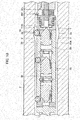
Fig. 3 ] It is a cross-sectional view showing a working head of the hole inner-surface cutting apparatus. - [
Fig. 4 ] (a) and (b) are cross-sectional views showing fluid pressure passages in the working head. - [
Fig. 5 ] It is a brock diagram showing configuration of the hole inner-surface cutting apparatus. - [
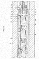
Fig. 6 ] It is a cross-sectional view while the working head passes over a circumferential protrusion on the inner surface of the workpiece (before passing over). - [
Fig. 7 ] It is a cross-sectional view while the working head passes over the circumferential protrusion on the inner surface of the workpiece (during passing over). - [
Fig. 8 ] It is a cross-sectional view while the working head passes over the circumferential protrusion on the inner surface of the workpiece (after passing over). - [
Fig. 9 ] It is a cross-sectional view while the working head passes over a circumferential groove on the inner surface of the workpiece (before passing over). - [
Fig. 10 ] It is a cross-sectional view while the working head passes over the circumferential groove on the inner surface of the workpiece (during passing over). - [
Fig. 11 ] It is a cross-sectional view while the working head passes over the circumferential groove on the inner surface of the workpiece (after passing over). - [
Fig. 12 ] It is a flowchart of an oil pressure control while the working head passes over the circumferential protrusion (the circumferential groove) on the inner surface of the workpiece. - A hole inner-surface cutting apparatus (a hole inner-surface cutting method) according to an embodiment will be explained. First, overall configuration of the hole inner-surface cutting apparatus 1 is explained. As shown in
Fig. 1 , the hole inner-surface cutting apparatus 1 includes aworkpiece hold device 10 located at its center, ahead stroke device 30 located on one side (on a left side inFig. 1 ) of theworkpiece hold device 10, and ahead rotation device 40 located on the other side (on a right side inFig. 1 ) of theworkpiece hold device 10. The workpiece holddevice 10, thehead stroke device 30 and thehead rotation device 40 are arranged so as to be aligned in line on a table 50. Note that the workpiece holddevice 10, thehead stroke device 30 and thehead rotation device 40 may be disposed so as to be aligned vertically on a wall surface. - A
workpiece 2 in the present embodiment is a long hollow shaft as shown inFig. 2 , for example. Thehollow shaft 2 has an about three meter length, and each diameter at its both ends is expanded. In thehollow shaft 2, a penetratinghole 2h are formed along its axial direction. Each inner diameter at both ends of the penetratinghole 2h is also expanded. An inner diameter at the center of the penetratinghole 2h is almost 90mm. Acircumferential protrusion 2r or acircumferential groove 2g that will be explained later is formed on an inner surface of the penetratinghole 2h, but not shown inFig. 2 . Note that the workpiece in the present embodiment is thehollow shaft 2, but it is not limited to the hollow shaft as shown inFig. 2 as long as a penetrating hole is formed therein. Thehollow shaft 2 is shown schematically inFig. 1 by dot-and-dash lines. - The workpiece hold
device 10 holds thehollow shaft 2 while cutting the inner surface of the penetratinghole 2h of the hollow shaft (workpiece) 2. Thehollow shaft 2 is held so that its axial direction coincides with a travel direction of an after-explained workinghead 20. Theworkpiece hold device 10 has a pair ofchucks hollow shaft 2. Specifically, each thechucks Plural holders 14 for supporting thehollow shaft 2 from beneath or clamping thehollow shaft 2 are also provided between the pairedchucks hollow shaft 2 is held by thechucks holders 14 so that the axial direction of the penetratinghole 2h coincides with the travel direction of the working head 20 (so that thehollow shaft 2 never curves). Note that, in a case where theworkpiece 2 is not a hollow shaft, the workpiece holddevice 10 hold theworkpiece 2 so that an axial direction of a penetrating hole (2h) formed in aworkpiece 2 coincides with the travel direction of the workinghead 20. - The working
head 20 for cutting the inner surface of the penetratinghole 2h of thehollow shaft 2 is coupled with an after-explainedrotation rod 41 at its one end (a headrotatable body 20b), and inserted into the penetratinghole 2h from one end of the penetratinghole 2h of thehollow shaft 2 held by theworkpiece hold device 10. Then, astroke rod 31 is coupled with the other end (a headmain body 20a) of the workinghead 20 on a side of the other end of the penetratinghole 2h. Alternatively, the workinghead 20 is inserted into the penetratinghole 2h after being coupled with thehead stroke rod 31, and further coupled with thehead rotation rod 41. The workinghead 20 will be explained later in detail. - The
head stroke device 30 includes thehead stroke rod 31 and arod stroke mechanism 32. A distal end (a right end inFig. 1 ) of thehead stroke rod 31 is coupled (fixed) with the working head 20 (the headmain body 20a). Threefluid pressure passages 31a (seeFig. 4 ) for supplying oil pressure to the workinghead 20 are provided in thehead stroke rod 31. Thefluid pressure passages 31a are connected with an after-explainedoil pressure unit 60. Thefluid pressure passages 31a will be explained later together with theoil pressure unit 60 and the workinghead 20. - The
head stroke mechanism 32 strokes theworking head 20 coupled with the distal end of thehead stroke rod 31 by stroking thehead stroke rod 31. Thehead stroke mechanism 32 includes ablock 32a fixed with a base end of thehead stroke rod 31, afeed screw 32c screwed with afeed hole 32b formed in theblock 32a, and a stroke drive source (feed motor) 32d for rotating thefeed screw 32c. Thefeed screw 32c is disposed in parallel to thehead stroke rod 31. Thefeed screw 32c strokes, by being rotated by thefeed motor 32d, thehead stroke rod 31 and the workinghead 20 in a center axial direction of the working head 20 (i.e. in the axial direction of the penetratinghole 2h of thehollow shaft 2 held by the workpiece hold device 10) by the intermediary of theblock 32a (thefeed hole 32b). Thefeed motor 32d is connected with an after-explained controller (control console) 70 and controlled by thecontroller 70. - Note that structure of the
head stroke mechanism 32 is not limited to the above-explained structure as long as it can stroke thehead stroke rod 31 and the workinghead 20 with high precision. For example, ball screw mechanism, rack and pinion mechanism, belt/chain mechanism, a liner actuator and so on can be adopted. - The
head rotation device 40 includes thehead rotation rod 41 and arod rotation mechanism 42. A distal end (a left end inFig. 1 ) of thehead rotation rod 41 is coupled (fixed) with (the headrotatable body 20b of) the workinghead 20. Aslide shaft 41a for shifting acutting tool 20 of the workinghead 20 in a direction perpendicular to the center axial direction of the working head 20 (in a direction perpendicular to the axial direction of the penetratinghole 2h, i.e. a radial direction of the penetratinghole 2h) is accommodated slidably in thehead rotation rod 41. Acoolant supply passage 41b (a supply passage of cutting fluid: seeFig. 3 ) for supplying the cutting fluid (coolant) to the workinghead 20 is also provided in thehead rotation rod 41. Thecoolant supply passage 41b is connected with an after-explained coolant unit80. Thecoolant supply passage 41b will be explained later together with thecoolant unit 80 and the workinghead 20. - The
rod rotation mechanism 42 rotates, by rotating thehead rotation rod 41, the headrotatable body 20b of the workinghead 20 coupled with the distal end of thehead rotation rod 41. Therod rotation mechanism 42 includes aslide base 42a slidable on the table and arotation drive source 42b that is provided on theslide base 42a and rotates thehead rotation rod 41. When the workinghead 20 is stroked by the above-explainedhead stroke device 30, theslide base 42a slides along with the stroke of the workinghead 20. Therotation drive source 42b holds thehead rotation rod 41 rotatably, and rotates thehead rotation rod 41 by its rotation motor via a gear mechanism. Therotation drive source 42b is connected with the after-explained controller (control console) 70 and controlled by thecontroller 70. - The
rod rotation mechanism 42 also includes astationary holder 42c and amovable holder 42d that support thehead rotation rod 41 rotatably. Thestationary holder 42c is fixed on the table 50. Themovable holder 42d is slidable between theslide base 42a and thestationary holder 42c. Themovable holder 42d is tethered with theslide base 42a by a wire, a chain or the like. Anactuator 42e for sliding the above-explainedslide shaft 41a is also provided on theslide base 42a. Shifting of thecutting tool 20c of the workinghead 20 by theactuator 42e will be explained later. Also theactuator 42e is connected with the controller (control console) 70 and controlled by thecontroller 70. - Next, the working
head 20 will be explained. As shown inFig. 3 , the workinghead 20 is comprised of the headmain body 20a that doesn't rotate and the headrotatable body 20b that is rotatable. The headmain body 20a and the headrotatable body 20b are coupled with each other by the intermediary ofbearings 20d. As explained above, the headmain body 20a is coupled with the distal end of thehead stroke rod 31, and the headrotatable body 20b is coupled with the distal end of thehead rotation rod 41. - The head
main body 20a has a hollowcylindrical case 21. And, threepositioning mechanisms 22A to 22C are provided in thecase 21 along the center axial direction of the workinghead 20. Thepositioning mechanisms 22A to 22C position the workinghead 20 in the penetratinghole 2h so that the center axis of the workinghead 20 coincides with the axis of the penetratinghole 2h. The threepositioning mechanisms 22A to 22C will be called as afirst mechanism 22A, asecond mechanism 22B and athird mechanism 22C sequentially from the after-explainedcutting tool 20c of the headrotatable body 20b. - Orientations of the
positioning mechanisms 22A to 22C is not all the same, but they have identical configuration. In following explanations, thepositioning mechanisms 22A to 22C are collectively called as a positioning mechanism 22, and each configuration of them will be explained hereinafter. The positioning mechanism 22 has apiston 23, thefluid pressure chamber 24, threesliders 25, and freely-rotatable guide rollers 26. Thepiston 23 is slidable in the center axial direction of the workinghead 20. Thefluid pressure chamber 24 is formed on a base-end side of thepiston 23. Each of thesliders 25 can be slid in the radial direction of the workinghead 20 by thepiston 23. Each of theguide rollers 26 is provided on theslider 25 and pressed onto the inner surface of the penetratinghole 2h. A base end portion of thepiston 23 has a solid cylindrical shape and a distal end portion thereof has a conical shape. Although a base end of thepiston 23 contacts with abulkhead 27 provided in an inside of thecase 21 inFig. 3 , a step is formed along a circumferential edge of the base end of thepiston 23 and thereby thefluid chamber 24 is formed by this step so as to be surrounded by an inner circumferential surface of thecase 21, thebulkhead 27 and thepiston 23. - As shown in
Fig. 4(a) and Fig. 4(b) , the above-explainedfluid pressure passages 31a provided in thehead stroke rod 31 are extended into thecase 21 of the headmain body 20a. When thehead stroke rod 31 and the headmain body 20a are coupled with each other, the threefluid pressure passages 31a are communicated with the threefluid pressure chambers 24, respectively. Thefluid pressure passages 31a formed in thecase 21 shown inFig. 4(a) and Fig. 4(b) are not needed to be arranged evenly when viewing along the center axial direction of the workinghead 20. As long as thefluid pressure passages 31a connect thefluid pressure passages 31a in thehead stroke rod 31 with the threefluid pressure chambers 24, respectively, their paths may be formed in various forms. However, paths with as little pressure loss as possible are designed. - Although the three
sliders 25 are provided in the single positioning mechanism 22, the threesliders 25 are radially arranged evenly (i.e. every central angle 120°) when viewing along the center axial direction of the working head 20 (only one of thesliders 25 can been seen inFig. 3 ). An inner end of theslider 25 has an inclination associating with a slope of the conical portion of thepiston 23. Therefore, the threesliders 25 are pushed outward evenly in the radial directions when thepiston 23 is slid (actuated) toward a side of thesliders 25 by the fluid pressure in thefluid pressure chamber 24. As the result, theguide rollers 26 attached to outer ends of thesliders 25, respectively, are evenly pressed onto the inner surface of the penetratinghole 2h. When the threeguide rollers 26 are evenly pressed onto the inner surface of the penetratinghole 2h, the center axis of the workinghead 20 is made coincident with the axis of the penetratinghole 2h. - Note that a
guide pin 28 is protruded oppositely to thepiston 23 and theguide pin 28 is inserted into aguide hole 29 formed in thepiston 23. Theguide pin 28 and theguide hole 29 are parallel to the center axis of the workinghead 20, and guide sliding of thepiston 23. Thepiston 23 is restricted from inclining by theguide pin 28 and theguide hole 29, and thereby thepiston 23 can slide smoothly. - In the present embodiment, the
sliders 25 of thefirst mechanism 22A, thefluid pressure chamber 24 of thefirst mechanism 22A, thesliders 25 of thesecond mechanism 22B, thefluid pressure chamber 24 of thesecond mechanism 22B, thefluid pressure chamber 24 of thethird mechanism 22C, and thesliders 25 of thethird mechanism 22C are disposed in this order from thecutting tool 20c along the center axis of the workinghead 20. Note that thepiston 23 is inevitably disposed between thefluid pressure chamber 24 and theslider 25. In other words, the sliders 25 (the guide rollers 26) are disposed on a side of thecutting tool 20c in thefirst mechanism 22A and thesecond mechanism 22B that are closer to thecutting tool 20c, and thefluid pressure chamber 24 is disposed on a side of thecutting tool 20c in thethird mechanism 22C that is farthest from thecutting tool 20c. This arrangement will be explained later in detail. - Since the three positioning mechanisms 22 (22A to 22C) for making the center axis of the working
head 20 coincident with the axis of the penetratinghole 2h are provided along the center axis as explained above, the headmain body 20a, i.e. the workinghead 20, can be positioned with high precision without inclination in the penetratinghole 2h. The after-explainedcutting tool 20c on the headrotatable body 20b can be also positioned with high precision due to the high precision positioning of the workinghead 20, and thereby cutting can be done with high precision. - As shown in
Fig. 3 , the headrotatable body 20b coupled with the headmain body 20a by the intermediary of thebearings 20d has arotation body 20e that is rotatable and thecutting tool 20c accommodated in therotation body 20e. Thecutting tool 20c is slidable in the above-explained radial direction, and the cuttinginsert 20f is fixed onto its distal end. Pluralinclined mating grooves 20g are formed on a flat side face of a base end portion of thecutting tool 20c. - Plural inclined mated
grooves 41c are also formed on the distal end of the above-explainedslide shaft 41a provided within thehead rotation rod 41. Themating grooves 20g and the matedgrooves 41c are slidably mated mutually. Therefore, when theslide shaft 41a slides, thecutting tool 20c is shifted in the radial direction due to mating between themating grooves 20g and the matedgrooves 41c. Namely, themating grooves 20g, the matedgrooves 41c, theslide shaft 41a and theactuator 42e configures a cutting tool shift mechanism that can shift thecutting tool 20c in the radial direction. By shifting thecutting tool 20c in the radial direction, the position of the cuttinginsert 20f can be adjusted and a cutting diameter can be adjusted. This adjustment of the cutting diameter can be done while the headrotatable body 20b rotates. Namely, the cutting diameter can be adjusted while the inner surface of the penetratinghole 2h is cut. - In
Fig. 3 , thecutting tool 20c is retracted into therotation body 20e. The workinghead 20 is inserted into the penetratinghole 2h in this state, so that the cuttinginsert 20f can be protected. When the inner surface of the penetratinghole 2h is to be cut, thecutting tool 20c is protruded in the radial direction from the state shown inFig. 3 (seeFig. 6 to Fig. 11 ). - Note that, with respect to the
slide shaft 41a, only its distal end portion on which the matedgrooves 41c are formed rotates together with thehead rotation rod 41 and its base end portion from the distal end portion doesn't rotate, and the distal end portion and the base end portion are coupled with each other by the intermediary of a rotary joint. Namely, the base end portion of theslide shaft 41a is slid without rotating within the rotating hollowhead rotation rod 41. - In addition, three positioning mechanisms 22 (22A to 22C) are provided in the present embodiment, but four or more may be provided as long as at least three are provided. Further, the three sliders 25 (the three guide rollers 26) are provided in the present embodiment in each of the positioning mechanisms 22, but four or more may be provided as long as at least three are provided. However, in order to make its mechanism as simple as possible and to make the center axis of the working
head 20 coincide with the axis of the penetratinghole 2h, it is most preferable to provide the three sliders 25 (the three guide rollers 26) in each of the positioning mechanisms 22. - Furthermore, the inner surface of the penetrating
hole 2h of thehollow shaft 2 is cut by the cutting tool 2c while thehead stroke rod 31 is pulled (leftward inFig. 1 andFig. 3 ). By preparing acutting tool 20c that has different orientation, the inner surface of the penetratinghole 2h of thehollow shaft 2 may be cut by thecutting tool 20c while thehead stroke rod 31 is pushed (rightward inFig. 1 andFig. 3 ). - Subsequently, system configuration of the hole inner-surface cutting apparatus 1 including the
oil pressure unit 60, thecontroller 70, thecoolant unit 80 and so on that have been mentioned above will be explained with reference to a block diagram shown inFig. 5 . As shown inFig. 5 , thecontroller 70 is connected also with theoil pressure unit 60 and controls theoil pressure unit 60. Theoil pressure unit 60 has anoil tank 61 and anoil pump 62 that generate fluid pressure to be supplied to thefluid pressure chambers 24 of the positioning mechanisms 22. Note that oil whose fluid pressure has been increased by theoil pump 62 may be accumulated in theoil tank 61 and then supplied to thefluid pressure chambers 24. Theoil tank 61 and theoil pump 62 configures a fluid pressure source that supplies the fluid pressure to thefluid pressure chambers 24. - The above-explained
fluid pressure passages 31a are branched from the single fluid pressure source.Valve mechanisms 63 for adjusting fluid pressures to be supplied to thepressure chambers 24 are provided on thefluid pressure passages 31a branched in three, respectively. Therefore, the fluid pressures of the threefluid pressure chambers 24 can be adjusted independently from each other by thevalve mechanisms 63. Thevalve mechanisms 63 in the present embodiment are pressure reduction valves. Thevalve mechanisms 63 are controlled by thecontroller 70, and thereby the fluid pressure in the desiredfluid pressure chamber 24 is reduced. When the fluid pressure in thefluid pressure chamber 24 is reduced, a volumetric capacity of thefluid pressure chamber 24 reduces and thereby the sliders 25 (the guide rollers 26) are retracted into thecase 21. - The
controller 70 is connected also with thecoolant unit 80 and controls thecoolant unit 80. Thecoolant unit 80 has acoolant tank 81 and acoolant pump 82 for injecting coolant to the vicinity of thecutting tool 20c. Note that the coolant injected to the vicinity of thecutting tool 20c restricts frictions during cutting and cools heats generated by cutting. The coolant is recovered and then returned to thecoolant tank 81 again after cutting scraps are removed by areprocessing device 83. - As explained above, the
controller 70 is connected also with the stroke drive source (the feed motor) 32d of thehead stroke device 30 and controls the stroke of the workinghead 20. On this occasion, the stroke position of the workinghead 20 is recognized by thecontroller 70 based on the number of rotations of thefeed motor 32d (control information of the stroke drive source). Note that the stroke position of the workinghead 20 may be recognized not based on the number of rotations of thefeed motor 32d, but based on the number of rotations of thefeed screw 32c or the number of rotations of a gear if a gear mechanism is intervenient. Note that an initial position of the stroke position of the workinghead 20 is set after theworkpiece 2 is held on theworkpiece hold device 10 but before cutting is started. - In addition, the
controller 70 is connected also with the rotation drivesource 42b of thehead rotation device 40 and controls a rotational position of the headrotatable body 20b, i.e. thecutting tool 20c, of the workinghead 20. On this occasion, the rotational position of thecutting tool 20c is recognized by thecontroller 70 based on a state of the rotation drivesource 42b. Note that the rotational position of thecutting tool 20c may be recognized not based on the state of the very rotation drivesource 42b, but based on the number of rotations of a gear if a gear mechanism is intervenient. Note that an initial position of the rotational position of the workinghead 20 is set after theworkpiece 2 is held on theworkpiece hold device 10 but before cutting is started. - In addition, the
controller 70 is connected also with theactuator 42e of thehead rotation device 40 and controls the cutting diameter of thecutting tool 20c. On this occasion, the cutting diameter (the position in the radial direction) of thecutting tool 20c is recognized by thecontroller 70 based on a controlling state of theactuator 42e (control information of the cutting tool shift mechanism). Note that cutting diameter of thecutting tool 20c may be recognized not based on the state of theactuator 42e, but by providing a detector for detecting the slide position of theslide shaft 41a. Note that the cutting diameter of thecutting tool 20c is initially set (a position of the tip end of the cuttinginsert 20f is set) after theworkpiece 2 is held on theworkpiece hold device 10 but before cutting is started. - Subsequently, operations of the working
head 20 for cutting, by the hole inner-surface cutting apparatus 1 having the above configuration, the inner surface of the penetratinghole 2h on which acircumferential protrusion 2r is formed will be explained with reference to a flowchart shown inFig. 12 andFig. 6 toFig. 8 . InFig. 6 to Fig. 8 , shown is a case where theguide rollers 26 of thefirst mechanism 22A pass over thecircumferential protrusion 2r. The flowchart shown inFig. 12 is executed with respect to each of thefirst mechanism 22A to thethird mechanism 22C. Here, explanations will be made with thefirst mechanism 22A taken as an example as shown inFig. 6 to Fig. 8 . - Note that the working
head 20 is travelled by being pulled leftward in the figures by thehead stroke rod 31. Therefore, theguide rollers 26 of thefirst mechanism 22A pass over a local diameter-reduction portion X of thecircumferential protrusion 2r to run on thecircumferential protrusion 2r, and then pass over a local diameter-expansion portion Y of thecircumferential protrusion 2r to run past thecircumferential protrusion 2r. - As explained above, the initial position of the working
head 20 is set after thehollow shaft 2 has been installed. In addition, shape data of thehollow shaft 2 are also preliminarily input to thecontroller 70. Therefore, it is preliminarily recognized how long the workinghead 20 strokes from its initial position until theguide rollers 26 of thefirst mechanism 22A reach thecircumferential protrusion 2r. Thecontroller 70 keeps monitoring whether or not theguide rollers 26 of thefirst mechanism 22A get close to the local diameter-reduction portion X of thecircumferential protrusion 2r (step S10). For example, the step S10 is affirmed when theguide rollers 26 get to within a predetermined distance of the local diameter-reduction portion X. This predetermined distance may be set fixedly, or may be changed according to the stroke speed of the workinghead 20. - As shown in
Fig. 6 , when it is judged that theguide rollers 26 of thefirst mechanism 22A get close to the local diameter-reduction portion X of thecircumferential protrusion 2r (YES in step S10), the valve mechanism (the pressure reduction valve) 63 associating with thefirst mechanism 22A is controlled by thecontroller 70 to reduce the fluid pressure in thefluid pressure chamber 24 of thefirst mechanism 22A (step S20). Namely, the fluid pressure in thefluid pressure chamber 24 of thefirst mechanism 22A is made lower than the fluid pressure in thefluid pressure chambers 24 of thesecond mechanism 22B and thethird mechanism 22C. Since the fluid pressure in thefluid pressure chamber 24 of thefirst mechanism 22A is reduced, thesliders 25 are slid smoothly in a radially inner direction by being pushed by the local diameter-reduction portion X as shown inFig. 7 even when theguide rollers 26 reach the local diameter-reduction portion X of thecircumferential protrusion 2r due to stroking of the workinghead 20 and thereby stroking of the workinghead 20 never be interfered. - In addition, the
first mechanism 22A doesn't contribute the positioning of the workinghead 20 while the fluid pressure in thefluid pressure chamber 24 of thefirst mechanism 22A is reduced. However, the center axis of the workinghead 20 is made coincident with the axis of the penetratinghole 2h by the remaining two, the second mechanism 22b and thethird mechanism 22C, and thereby the position of thecutting tool 20c is controlled with high precision to maintain high precision cutting. After the step S20, thecontroller 70 keeps monitoring whether or not theguide rollers 26 of thefirst mechanism 22A have passed over the local diameter-reduction portion X of thecircumferential protrusion 2r (step S30). For example, the step S30 is affirmed when theguide rollers 26 get distanced from the local diameter-reduction portion X by a predetermined distance. This predetermined distance may be set fixedly, or may be changed according to the stroke speed of the workinghead 20. - When it is judged that the
guide rollers 26 of thefirst mechanism 22A have passed over the local diameter-reduction portion X of thecircumferential protrusion 2r (YES in step S30), the valve mechanism (the pressure reduction valve) 63 associating with thefirst mechanism 22A is controlled by thecontroller 70 to increase and restore the fluid pressure in thefluid pressure chamber 24 of thefirst mechanism 22A (step S40). Namely, the fluid pressure in thefluid pressure chamber 24 of thefirst mechanism 22A is increased to the fluid pressure in thefluid pressure chambers 24 of thesecond mechanism 22B and thethird mechanism 22C. Since the fluid pressure in thefluid pressure chamber 24 of thefirst mechanism 22A is restored, thesliders 25 are pushed radially outward and thereby theguide rollers 26 are pressed onto the inner surface of the penetratinghole 2h again as shown inFig. 8 . Therefore, the positioning of the workinghead 20 is done by all the threemechanisms 22A to 22C, and thereby the center axis of the workinghead 20 is made coincident with the axis of the penetratinghole 2h. Namely, the position of thecutting tool 20c is controlled with high precision, and thereby high precision cutting is maintained. - Note that, if a width of the
circumferential protrusion 2r is larger than the above-explained predetermined distance for monitoring that theguide rollers 26 pass over the local diameter-reduction portion X, there may be a case where thefluid pressure 24 is restored while theguide rollers 26 contact with an inner circumferential surface of thecircumferential protrusion 2r (seeFig. 7 ). In this case, theguide rollers 26 is moved radially outward by the restored fluid pressure in thefluid pressure chamber 24 after they reaches the local diameter-expansion portion Y and thereby they turn into a state shown inFig. 8 similarly. Also in this case, stroking of the workinghead 20 never be interfered. - Subsequently, operations of the working
head 20 for cutting, by the hole inner-surface cutting apparatus 1, the inner surface of the penetratinghole 2h on which acircumferential groove 2g is formed will be explained with reference to the flowchart shown inFig. 12 andFig. 9 toFig. 11 . InFig. 9 to Fig. 11 , shown is a case where theguide rollers 26 of thefirst mechanism 22A pass over thecircumferential groove 2g. The flowchart shown inFig. 12 can be applied not only to thecircumferential protrusion 2r but also to thecircumferential groove 2g, and is executed with respect to each of thefirst mechanism 22A to thethird mechanism 22C. Here, explanations will be made with thefirst mechanism 22A taken as an example as shown inFig. 9 to Fig. 11 . Theguide rollers 26 of thefirst mechanism 22A pass over the local diameter-expansion portion Y of thecircumferential groove 2g to enter into thecircumferential groove 2g, and then pass over the local diameter-reduction portion X of thecircumferential groove 2g to get across thecircumferential groove 2g. - Similarly to the above-explained case of the
circumferential protrusion 2r, thecontroller 70 keeps monitoring whether or not theguide rollers 26 of thefirst mechanism 22A get close to the local diameter-reduction portion X of thecircumferential groove 2g (step S10). As explained above, the step S10 is affirmed when theguide rollers 26 get to within a predetermined distance of the local diameter-reduction portion X. Namely, the fluid pressure in thefluid pressure chamber 24 is not controlled with respect to the previous local diameter-expansion portion Y of thecircumferential groove 2g. If theguide rollers 26 reach the local diameter-expansion portion Y before the fluid pressure control of thefluid pressure chamber 24 for the local diameter-reduction portion X is started, there may be a case where thesliders 25 are slid radially outward according to the fluid pressure in thefluid pressure chamber 24 and theguide rollers 26 are pressed onto a bottom surface of thecircumferential groove 2g. Of course, there may be a case where the step S10 is affirmed before theguide rollers 26 reach the local diameter-expansion portion Y. - In the present embodiment, in a state where the
guide rollers 26 of thefirst mechanism 22A get close to the local diameter-expansion portion Y of thecircumferential groove 2g as shown inFig.9 , it is not judged that they get close to the local diameter-reduction portion X (NO in step S10). However, it is judged that theguide rollers 26 get close to the local diameter-reduction portion X of thecircumferential groove 2g when theguide rollers 26 have entered onto thecircumferential groove 2g as shown inFig. 10 (YES in step S10: the above-explained predetermined diameter is shorter than a width of thecircumferential groove 2g). At this moment, theguide rollers 26 have been moved radially outward toward the bottom surface of thecircumferential groove 2g as explained above. - When the step S10 is affirmed, the valve mechanism (the pressure reduction valve) 63 associating with the
first mechanism 22A is controlled by thecontroller 70 to reduce the fluid pressure in thefluid pressure chamber 24 of thefirst mechanism 22A (step S20). Namely, the fluid pressure in thefluid pressure chamber 24 of thefirst mechanism 22A is made lower than the fluid pressure in thefluid pressure chambers 24 of thesecond mechanism 22B and thethird mechanism 22C. Since the fluid pressure in thefluid pressure chamber 24 of thefirst mechanism 22A is reduced, thesliders 25 are slid smoothly in a radially inner direction by being pushed by the local diameter-reduction portion X as shown inFig. 11 when theguide rollers 26 reach the local diameter-reduction portion X of thecircumferential groove 2g due to further stroking of the workinghead 20 and thereby stroking of the workinghead 20 never be interfered. - The
first mechanism 22A doesn't contribute the positioning of the workinghead 20 while the fluid pressure in thefluid pressure chamber 24 of thefirst mechanism 22A is reduced. However, the center axis of the workinghead 20 is made coincident with the axis of the penetratinghole 2h by the remaining two, thesecond mechanism 22B and thethird mechanism 22C, and thereby the position of thecutting tool 20c is controlled with high precision to maintain high precision cutting. After the step S20, thecontroller 70 keeps monitoring whether or not theguide rollers 26 of thefirst mechanism 22A have passed over the local diameter-expansion portion Y of thecircumferential groove 2g (step S30). As explained above, the step S30 is affirmed when theguide rollers 26 get distanced from the local diameter-reduction portion X by a predetermined distance. - When it is judged that the
guide rollers 26 of thefirst mechanism 22A have passed over the local diameter-reduction portion X of thecircumferential groove 2g (YES in step S30), the valve mechanism (the pressure reduction valve) 63 associating with thefirst mechanism 22A is controlled by thecontroller 70 to increase and restore the fluid pressure in thefluid pressure chamber 24 of thefirst mechanism 22A (step S40). Namely, the fluid pressure in thefluid pressure chamber 24 of thefirst mechanism 22A is increased to the fluid pressure in thefluid pressure chambers 24 of thesecond mechanism 22B and thethird mechanism 22C. Since the fluid pressure in thefluid pressure chamber 24 of thefirst mechanism 22A is restored, theguide rollers 26 are pressed onto the inner surface of the penetratinghole 2h again as shown inFig. 11 . Therefore, the positioning of the workinghead 20 is done by all the threemechanisms 22A to 22C, and thereby the center axis of the workinghead 20 is made coincident with the axis of the penetratinghole 2h. Namely, the position of thecutting tool 20c is controlled with high precision, and thereby high precision cutting is maintained. - According to the hole inner-surface cutting apparatus 1 in the present embodiment, the working
head 20 includes the (at least) three positioning mechanisms 22 (22A to 22C) along its center axis. And, the fluid pressures in thefluid pressure chambers 24 of the three positioning mechanisms 22 can be controlled by thecontroller 70 independently from each other. Therefore, even while any one of the three positioning mechanism 22 passes over thecircumferential protrusion 2r or thecircumferential groove 2g (i.e. the local diameter-reduction portion X) formed in the penetratinghole 2h, the center axis of the workinghead 20 is made coincident with the axis of the penetratinghole 2h by the at least two positioning mechanisms 22. Thus, the position of thecutting tool 20c can be maintained with high precision, and thereby high precision cutting can be done. - Especially, according to the hole inner-surface cutting method in the present embodiment, the fluid pressure in the fluid pressure chamber of the positioning mechanism 22 that passes over the
circumferential protrusion 2r or thecircumferential groove 2g (i.e. the local diameter-reduction portion X) is made lower than the fluid pressure in thepressure chambers 24 of the other positioning mechanisms 22 by thecontroller 70. Therefore, stroking of the workinghead 20 is never interfered by the local diameter-reduction portion X, and thereby the position of thecutting tool 20c can be controlled with high precision to maintain high precision cutting. - In the present embodiment, the fluid pressure to be supplied to the
pressure chambers 24 of the positioning mechanisms 22 is generated by the single fluid pressure source (theoil tank 61 and the oil pump 62), and then supplied to thepressure chambers 24 through thefluid pressure passages 31a independent from each other. And, thevalve mechanisms 63 for adjusting the fluid pressures are provided on thefluid pressure passages 31a, respectively. Therefore, a uniform pressure can be regularly supplied to the pluralfluid pressure chambers 24 from the single fluid pressure source. Then, while any one of the positioning mechanisms 22 passes over thecircumferential protrusion 2r or thecircumferential groove 2g (i.e. the local diameter-reduction portion X), only the fluid pressure in thefluid pressure chamber 24 of the said positioning mechanism 22 can be adjusted by thevalve mechanism 63. Thus, the supply system of the fluid pressure(s) can be configured simply, and the fluid pressure control can be done reliably. - In addition, in the present embodiment, the
sliders 25 of thefirst mechanism 22A, thefluid pressure chamber 24 of thefirst mechanism 22A, thesliders 25 of thesecond mechanism 22B, thefluid pressure chamber 24 of thesecond mechanism 22B, thefluid pressure chamber 24 of thethird mechanism 22C, and thesliders 25 of thethird mechanism 22C are disposed in this order from thecutting tool 20c along the center axis of the workinghead 20. Since thesliders 25, i.e. theguide rollers 26, of thefirst mechanism 22A are disposed closest to thecutting tool 20c, the position of thecutting tool 20c can be kept with high precision and thereby high precision cutting can be done. Here, while the guide rollers of thefirst mechanism 22A pass over thecircumferential protrusion 2r or thecircumferential groove 2g (i.e. the local diameter-reduction portion X), thefirst mechanism 22A doesn't contribute the positioning of the workinghead 20. However, since thesliders 25, i.e. theguide rollers 26, of thesecond mechanism 22B is disposed as close as possible to thecutting tool 20c, the position of the workinghead 20 can be kept with high precision and high precision cutting can be done. Here, the sliders 25 (the guide rollers 26) of thethird mechanism 22C are disposed as far as possible from the sliders 25 (the guide rollers 26) of thesecond mechanism 22B. Therefore, the axis of the workinghead 20 in the penetratinghole 2h can be effectively restricted from inclining by thesecond mechanism 22B and thethird mechanism 22C, and thereby the high precision cutting can be done. - Further, in the present embodiment, the
fluid supply passages 31a are provided in thehead stroke rod 31 and the headmain body 20a, and thecoolant supply passage 41a is provided in thehead rotation rod 41 and the headrotatable body 20b. By separating the both passages in this manner, the fluid pressure (s) and the coolant can be supplied to the workinghead 20 reliably. In addition, the passages can be formed simply in the workinghead 20 by separating the both passages, and thereby the workinghead 20 can be downsized. As the result, it becomes possible to deal with a penetrating hole whose diameter is smaller. In addition, since the coolant is supplied to the headrotatable body 20b, i.e. to the vicinity of thecutting tool 20c, cutting can be done stably. - Furthermore, in the present embodiment, the stroke position of the working
head 20 is detected by thecontroller 70 based on the number of rotations of thefeed motor 32d (the control information of the stroke drive source). Therefore, it is needless to provide a sensor for detecting the stroke position, and thereby high precision cutting can be done with simple configuration. Since approach of any of the positioning mechanisms 22 (any set of the guide rollers 26) to thecircumferential protrusion 2r or thecircumferential grooves 2g (i.e. the local diameter-reduction portion X) is also detected by this stroke position, it contributes the high precision cutting in view of this point. - Similarly, the cutting diameter (the position in the radial direction) of the
cutting tool 20c is detected by thecontroller 70 based of the control state of theactuator 42e (the control information of the cutting tool shift mechanism). Therefore, it is needless to provide a sensor for detecting the cutting diameter, and thereby high precision cutting can be done with simple configuration. - In addition, in the present embodiment, since any of the positioning mechanisms 22 (any set of the guide rollers 26) passes over the
circumferential protrusion 2r or thecircumferential groove 2g (i.e. the local diameter-reduction portion X) and then the fluid pressure of thefluid pressure chamber 24 associated therewith is restored, high precision cutting can be done stably while not being affected from thecircumferential protrusion 2r or thecircumferential grooves 2g (i.e. the local diameter-reduction portion X). - The hole inner-surface cutting apparatus and method according to the disclosure can be utilized as an apparatus and a method for cutting an inner surface of a penetrating hole formed in a workpiece.
Claims (8)
- A hole inner-surface cutting apparatus for cutting an inner surface of a penetrating hole formed in a workpiece, the apparatus comprising:a workpiece hold device that holds the workpiece;a working head capable of being inserted into the penetrating hole, and including a head rotatable body that has a cutting tool for cutting the inner surface of the penetrating hole and is rotatable about a center axis thereof and a head main body that rotatably holds the head rotatable body;a head rotation rod capable of being inserted into the penetrating hole from an end of the penetrating hole, and coupled with the head rotatable body to rotate the head rotatable body by being rotated by a rotation drive source; anda head stroke rod capable of being inserted into the penetrating hole from another end of the penetrating hole, and coupled with the head main body to stroke the working head in an axial direction of the penetrating hole by being stroked by a stroke drive source, whereina cutting tool shift mechanism for shifting the cutting tool in a radial direction perpendicular to the axial direction is provided in the head rotatable body of the working head and the head rotation rod,a plurality of positioning mechanisms for positioning the working head along the radial direction in the penetrating hole is provided at at least three positions along the axial direction in the head main body,each of the positioning mechanisms has at least three sliders radially arranged evenly and slidable in the radial direction, guide rollers respectively disposed on distal ends of the sliders and contacting with the inner surface of the penetrating hole, a piston for pressing the sliders outward in the radial direction, and a fluid pressure chamber for actuating the piston, andthe hole inner-surface cutting apparatus further comprises a controller configured to control fluid pressures in the fluid pressure chambers of the positioning mechanisms independently from each other.
- The hole inner-surface cutting apparatus according to claim 1, wherein
the hole inner-surface cutting apparatus further comprising:a fluid pressure source for supplying fluid pressure to the fluid pressure chambers;fluid pressure passages connecting the fluid pressure source with the fluid pressure chambers, respectively; andvalve mechanisms provided on the fluid pressure passages to adjust the fluid pressures to be supplied to the pressure chambers, respectively, by being controlled by the controller. - The hole inner-surface cutting apparatus according to claim 2, wherein
the head stroke rod and the head main body include the fluid pressure passages, and
the head rotation rod and the head rotatable body include a supply passage for supplying cutting fluid to a vicinity of the cutting tool. - The hole inner-surface cutting apparatus according to any one of claims 1 to 3, wherein
the stroke drive source is controlled by the controller, and the controller detects a position of the working head in the axial direction in the penetrating hole based on control information of the stroke drive source. - The hole inner-surface cutting apparatus according to any one of claims 1 to 4, wherein
the cutting tool shift mechanism is controlled by the controller, and the controller detects a position of the cutting tool in the radial direction in the penetrating hole based on control information of the cutting tool shift mechanism. - A hole inner-surface cutting method for cutting an inner surface of a penetrating hole formed in a workpiece, the method comprising:in cutting the inner surface of the penetrating hole by using the hole inner-surface cutting apparatus according to claim 1,when one of the positioning mechanism gets close to a local diameter-reduction portion in which the inner diameter of the penetrating hole locally reduces, making a pressure in the fluid pressure chamber of the positioning mechanism associating with the local diameter-reduction portion lower than pressures in the fluid pressure chambers of the other positioning mechanisms.
- The hole inner-surface cutting method according to claim 6, wherein
the stroke drive source is controlled by the controller, and the controller detects a position of the working head in the axial direction in the penetrating hole based on control information of the stroke drive source, and
the method further comprises: monitoring, by the controller, that the one of the positioning mechanisms gets close to the local diameter-reduction portion. - The hole inner-surface cutting method according to claim 6 or 7, further comprising:
after the one of the positioning mechanisms passes over the local diameter-reduction portion, restoring, by the valve mechanisms, the pressure in the fluid pressure chamber of the positioning mechanism associating with the local diameter-reduction portion to the pressures in the fluid pressure chambers of the other positioning mechanisms.
Applications Claiming Priority (2)
| Application Number | Priority Date | Filing Date | Title |
|---|---|---|---|
| JP2017077283 | 2017-04-10 | ||
| PCT/JP2018/008770 WO2018190038A1 (en) | 2017-04-10 | 2018-03-07 | Device and method for cutting hole inner surface |
Publications (3)
| Publication Number | Publication Date |
|---|---|
| EP3560642A1 true EP3560642A1 (en) | 2019-10-30 |
| EP3560642A4 EP3560642A4 (en) | 2020-08-26 |
| EP3560642B1 EP3560642B1 (en) | 2022-01-26 |
Family
ID=63792461
Family Applications (1)
| Application Number | Title | Priority Date | Filing Date |
|---|---|---|---|
| EP18784421.2A Active EP3560642B1 (en) | 2017-04-10 | 2018-03-07 | Hole inner-surface cutting apparatus |
Country Status (4)
| Country | Link |
|---|---|
| US (1) | US10946456B2 (en) |
| EP (1) | EP3560642B1 (en) |
| JP (1) | JP6791369B2 (en) |
| WO (1) | WO2018190038A1 (en) |
Families Citing this family (2)
| Publication number | Priority date | Publication date | Assignee | Title |
|---|---|---|---|---|
| EP3575023B1 (en) * | 2018-05-28 | 2021-02-17 | Koninklijke Luchtvaart Maatschappij N.V. | Inner shaft machining tool and method |
| KR102498608B1 (en) * | 2020-09-14 | 2023-02-10 | (주)경일에프비 | serration broach |
Family Cites Families (13)
| Publication number | Priority date | Publication date | Assignee | Title |
|---|---|---|---|---|
| US2257609A (en) * | 1941-06-25 | 1941-09-30 | Bernard M Kollath | Pilot for boring bars |
| JPS585122B2 (en) * | 1978-08-29 | 1983-01-29 | 日本鋼管株式会社 | Internal deburring, cleaning and coating equipment for pressure welding long medium and small diameter pipes |
| JPS6374017A (en) | 1986-09-18 | 1988-04-04 | Furukawa Electric Co Ltd:The | Method for ratating mirror for observing cylinder inner surface |
| JPH068105B2 (en) | 1987-08-03 | 1994-02-02 | 株式会社日立製作所 | In-pipe self-propelled inspection device and its configuration method |
| US5062187A (en) * | 1989-09-27 | 1991-11-05 | Scott Tech International, Inc. | Internal cutting head for drifting pipe |
| JPH069814A (en) | 1992-05-29 | 1994-01-18 | Central Glass Co Ltd | Method for stabilizing 1,1-dichloro-1-fluoroethane |
| JP2560413Y2 (en) * | 1992-07-10 | 1998-01-21 | 日本鋼管株式会社 | Internal bead cutting device for ERW pipe |
| JP3337996B2 (en) * | 1999-03-02 | 2002-10-28 | 株式会社牧野フライス製作所 | Deep hole processing device and deep hole measuring device |
| JP5440756B2 (en) | 2008-03-10 | 2014-03-12 | 株式会社Ihi | Long shaft inner surface processing apparatus and method |
| JP5354172B2 (en) | 2009-02-19 | 2013-11-27 | 株式会社Ihi | Internal processing equipment |
| JP5748052B2 (en) | 2011-06-13 | 2015-07-15 | 株式会社Ihi | Long nozzle inner surface processing equipment |
| JP5530981B2 (en) * | 2011-06-27 | 2014-06-25 | 東日本旅客鉄道株式会社 | Pipe cutting jig, plate material insertion method and element insertion method using the pipe cutting jig |
| JP6248968B2 (en) * | 2015-03-06 | 2017-12-20 | Jfeスチール株式会社 | Cutting device and method for inner surface of pipe end |
-
2018
- 2018-03-07 WO PCT/JP2018/008770 patent/WO2018190038A1/en not_active Ceased
- 2018-03-07 JP JP2019512384A patent/JP6791369B2/en active Active
- 2018-03-07 EP EP18784421.2A patent/EP3560642B1/en active Active
-
2019
- 2019-07-16 US US16/512,792 patent/US10946456B2/en active Active
Also Published As
| Publication number | Publication date |
|---|---|
| US10946456B2 (en) | 2021-03-16 |
| JPWO2018190038A1 (en) | 2019-12-12 |
| EP3560642A4 (en) | 2020-08-26 |
| EP3560642B1 (en) | 2022-01-26 |
| WO2018190038A1 (en) | 2018-10-18 |
| JP6791369B2 (en) | 2020-11-25 |
| US20190337058A1 (en) | 2019-11-07 |
Similar Documents
| Publication | Publication Date | Title |
|---|---|---|
| EP2095896B1 (en) | Machine tool and workpiece inner surface machining method using the machine tool | |
| US8015902B2 (en) | Machine tool and workpiece inner surface machining method using the machine tool | |
| US8573100B2 (en) | Loading magazine with moveable channel system for loading and unloading automatic lathes | |
| CN111727097B (en) | Differential housing machining machine | |
| US10946456B2 (en) | Apparatus and method for cutting inner surface of hole | |
| JP6833710B2 (en) | Machine tools and processing methods using machine tools | |
| JP5262576B2 (en) | Thread groove grinding device rest device and thread groove grinding device | |
| KR20140072808A (en) | Clamping device for portable boring machine and portable air-drive-drilling machine with clamping device | |
| JP3361959B2 (en) | Machine tool with eccentric spindle | |
| JP2002500106A (en) | Spring winding machine | |
| TW201821187A (en) | Machining apparatus, method for using machining apparatus and chuck device | |
| US5797303A (en) | Sleeve bore machining apparatus and sleeve bore machining method | |
| EP4043127A1 (en) | Boring cutting tool, boring machine and boring method | |
| US20210276100A1 (en) | Lathe | |
| JP6768154B2 (en) | Tool change control method for machine tools | |
| CN111182988B (en) | Hole processing machine and method for processing elliptical hole and inner diameter-variable hole using same | |
| US10363611B2 (en) | Rotation tool having function of fixing workpiece | |
| JP4169678B2 (en) | Honing tool | |
| JP4697393B2 (en) | Circular hole processing apparatus and processing method | |
| KR101518061B1 (en) | Machine tool that oval processing is available | |
| JP5333033B2 (en) | Guided reamer and processing method using guided reamer | |
| JP2006321040A (en) | Cutting tools | |
| KR101959174B1 (en) | Ball stud processing method | |
| US12257636B2 (en) | Lathe with chuck | |
| CN220145621U (en) | End face superfinishing grinding head and superfinishing grinding equipment |
Legal Events
| Date | Code | Title | Description |
|---|---|---|---|
| STAA | Information on the status of an ep patent application or granted ep patent |
Free format text: STATUS: THE INTERNATIONAL PUBLICATION HAS BEEN MADE |
|
| PUAI | Public reference made under article 153(3) epc to a published international application that has entered the european phase |
Free format text: ORIGINAL CODE: 0009012 |
|
| STAA | Information on the status of an ep patent application or granted ep patent |
Free format text: STATUS: REQUEST FOR EXAMINATION WAS MADE |
|
| 17P | Request for examination filed |
Effective date: 20190725 |
|
| AK | Designated contracting states |
Kind code of ref document: A1 Designated state(s): AL AT BE BG CH CY CZ DE DK EE ES FI FR GB GR HR HU IE IS IT LI LT LU LV MC MK MT NL NO PL PT RO RS SE SI SK SM TR |
|
| AX | Request for extension of the european patent |
Extension state: BA ME |
|
| DAV | Request for validation of the european patent (deleted) | ||
| DAX | Request for extension of the european patent (deleted) | ||
| A4 | Supplementary search report drawn up and despatched |
Effective date: 20200729 |
|
| RIC1 | Information provided on ipc code assigned before grant |
Ipc: B23B 29/02 20060101AFI20200723BHEP Ipc: B23B 41/02 20060101ALI20200723BHEP Ipc: B23B 29/034 20060101ALI20200723BHEP |
|
| REG | Reference to a national code |
Ref country code: DE Ref legal event code: R079 Ref document number: 602018030138 Country of ref document: DE Free format text: PREVIOUS MAIN CLASS: B23B0049000000 Ipc: B23B0029020000 |
|
| RIC1 | Information provided on ipc code assigned before grant |
Ipc: B23B 41/02 20060101ALI20210226BHEP Ipc: B23B 29/034 20060101ALI20210226BHEP Ipc: B23B 29/02 20060101AFI20210226BHEP |
|
| GRAP | Despatch of communication of intention to grant a patent |
Free format text: ORIGINAL CODE: EPIDOSNIGR1 |
|
| STAA | Information on the status of an ep patent application or granted ep patent |
Free format text: STATUS: GRANT OF PATENT IS INTENDED |
|
| INTG | Intention to grant announced |
Effective date: 20210412 |
|
| GRAJ | Information related to disapproval of communication of intention to grant by the applicant or resumption of examination proceedings by the epo deleted |
Free format text: ORIGINAL CODE: EPIDOSDIGR1 |
|
| STAA | Information on the status of an ep patent application or granted ep patent |
Free format text: STATUS: REQUEST FOR EXAMINATION WAS MADE |
|
| INTC | Intention to grant announced (deleted) | ||
| GRAP | Despatch of communication of intention to grant a patent |
Free format text: ORIGINAL CODE: EPIDOSNIGR1 |
|
| STAA | Information on the status of an ep patent application or granted ep patent |
Free format text: STATUS: GRANT OF PATENT IS INTENDED |
|
| INTG | Intention to grant announced |
Effective date: 20210913 |
|
| GRAS | Grant fee paid |
Free format text: ORIGINAL CODE: EPIDOSNIGR3 |
|
| GRAA | (expected) grant |
Free format text: ORIGINAL CODE: 0009210 |
|
| STAA | Information on the status of an ep patent application or granted ep patent |
Free format text: STATUS: THE PATENT HAS BEEN GRANTED |
|
| AK | Designated contracting states |
Kind code of ref document: B1 Designated state(s): AL AT BE BG CH CY CZ DE DK EE ES FI FR GB GR HR HU IE IS IT LI LT LU LV MC MK MT NL NO PL PT RO RS SE SI SK SM TR |
|
| REG | Reference to a national code |
Ref country code: GB Ref legal event code: FG4D |
|
| REG | Reference to a national code |
Ref country code: CH Ref legal event code: EP |
|
| REG | Reference to a national code |
Ref country code: AT Ref legal event code: REF Ref document number: 1464867 Country of ref document: AT Kind code of ref document: T Effective date: 20220215 |
|
| REG | Reference to a national code |
Ref country code: IE Ref legal event code: FG4D |
|
| REG | Reference to a national code |
Ref country code: DE Ref legal event code: R096 Ref document number: 602018030138 Country of ref document: DE |
|
| REG | Reference to a national code |
Ref country code: LT Ref legal event code: MG9D |
|
| REG | Reference to a national code |
Ref country code: NL Ref legal event code: MP Effective date: 20220126 |
|
| REG | Reference to a national code |
Ref country code: AT Ref legal event code: MK05 Ref document number: 1464867 Country of ref document: AT Kind code of ref document: T Effective date: 20220126 |
|
| PG25 | Lapsed in a contracting state [announced via postgrant information from national office to epo] |
Ref country code: NL Free format text: LAPSE BECAUSE OF FAILURE TO SUBMIT A TRANSLATION OF THE DESCRIPTION OR TO PAY THE FEE WITHIN THE PRESCRIBED TIME-LIMIT Effective date: 20220126 |
|
| PG25 | Lapsed in a contracting state [announced via postgrant information from national office to epo] |
Ref country code: SE Free format text: LAPSE BECAUSE OF FAILURE TO SUBMIT A TRANSLATION OF THE DESCRIPTION OR TO PAY THE FEE WITHIN THE PRESCRIBED TIME-LIMIT Effective date: 20220126 Ref country code: RS Free format text: LAPSE BECAUSE OF FAILURE TO SUBMIT A TRANSLATION OF THE DESCRIPTION OR TO PAY THE FEE WITHIN THE PRESCRIBED TIME-LIMIT Effective date: 20220126 Ref country code: PT Free format text: LAPSE BECAUSE OF FAILURE TO SUBMIT A TRANSLATION OF THE DESCRIPTION OR TO PAY THE FEE WITHIN THE PRESCRIBED TIME-LIMIT Effective date: 20220526 Ref country code: NO Free format text: LAPSE BECAUSE OF FAILURE TO SUBMIT A TRANSLATION OF THE DESCRIPTION OR TO PAY THE FEE WITHIN THE PRESCRIBED TIME-LIMIT Effective date: 20220426 Ref country code: LT Free format text: LAPSE BECAUSE OF FAILURE TO SUBMIT A TRANSLATION OF THE DESCRIPTION OR TO PAY THE FEE WITHIN THE PRESCRIBED TIME-LIMIT Effective date: 20220126 Ref country code: HR Free format text: LAPSE BECAUSE OF FAILURE TO SUBMIT A TRANSLATION OF THE DESCRIPTION OR TO PAY THE FEE WITHIN THE PRESCRIBED TIME-LIMIT Effective date: 20220126 Ref country code: ES Free format text: LAPSE BECAUSE OF FAILURE TO SUBMIT A TRANSLATION OF THE DESCRIPTION OR TO PAY THE FEE WITHIN THE PRESCRIBED TIME-LIMIT Effective date: 20220126 Ref country code: BG Free format text: LAPSE BECAUSE OF FAILURE TO SUBMIT A TRANSLATION OF THE DESCRIPTION OR TO PAY THE FEE WITHIN THE PRESCRIBED TIME-LIMIT Effective date: 20220426 |
|
| PG25 | Lapsed in a contracting state [announced via postgrant information from national office to epo] |
Ref country code: PL Free format text: LAPSE BECAUSE OF FAILURE TO SUBMIT A TRANSLATION OF THE DESCRIPTION OR TO PAY THE FEE WITHIN THE PRESCRIBED TIME-LIMIT Effective date: 20220126 Ref country code: LV Free format text: LAPSE BECAUSE OF FAILURE TO SUBMIT A TRANSLATION OF THE DESCRIPTION OR TO PAY THE FEE WITHIN THE PRESCRIBED TIME-LIMIT Effective date: 20220126 Ref country code: GR Free format text: LAPSE BECAUSE OF FAILURE TO SUBMIT A TRANSLATION OF THE DESCRIPTION OR TO PAY THE FEE WITHIN THE PRESCRIBED TIME-LIMIT Effective date: 20220427 Ref country code: FI Free format text: LAPSE BECAUSE OF FAILURE TO SUBMIT A TRANSLATION OF THE DESCRIPTION OR TO PAY THE FEE WITHIN THE PRESCRIBED TIME-LIMIT Effective date: 20220126 Ref country code: AT Free format text: LAPSE BECAUSE OF FAILURE TO SUBMIT A TRANSLATION OF THE DESCRIPTION OR TO PAY THE FEE WITHIN THE PRESCRIBED TIME-LIMIT Effective date: 20220126 |
|
| PG25 | Lapsed in a contracting state [announced via postgrant information from national office to epo] |
Ref country code: IS Free format text: LAPSE BECAUSE OF FAILURE TO SUBMIT A TRANSLATION OF THE DESCRIPTION OR TO PAY THE FEE WITHIN THE PRESCRIBED TIME-LIMIT Effective date: 20220526 |
|
| REG | Reference to a national code |
Ref country code: DE Ref legal event code: R119 Ref document number: 602018030138 Country of ref document: DE |
|
| PG25 | Lapsed in a contracting state [announced via postgrant information from national office to epo] |
Ref country code: SM Free format text: LAPSE BECAUSE OF FAILURE TO SUBMIT A TRANSLATION OF THE DESCRIPTION OR TO PAY THE FEE WITHIN THE PRESCRIBED TIME-LIMIT Effective date: 20220126 Ref country code: SK Free format text: LAPSE BECAUSE OF FAILURE TO SUBMIT A TRANSLATION OF THE DESCRIPTION OR TO PAY THE FEE WITHIN THE PRESCRIBED TIME-LIMIT Effective date: 20220126 Ref country code: RO Free format text: LAPSE BECAUSE OF FAILURE TO SUBMIT A TRANSLATION OF THE DESCRIPTION OR TO PAY THE FEE WITHIN THE PRESCRIBED TIME-LIMIT Effective date: 20220126 Ref country code: MC Free format text: LAPSE BECAUSE OF FAILURE TO SUBMIT A TRANSLATION OF THE DESCRIPTION OR TO PAY THE FEE WITHIN THE PRESCRIBED TIME-LIMIT Effective date: 20220126 Ref country code: EE Free format text: LAPSE BECAUSE OF FAILURE TO SUBMIT A TRANSLATION OF THE DESCRIPTION OR TO PAY THE FEE WITHIN THE PRESCRIBED TIME-LIMIT Effective date: 20220126 Ref country code: DK Free format text: LAPSE BECAUSE OF FAILURE TO SUBMIT A TRANSLATION OF THE DESCRIPTION OR TO PAY THE FEE WITHIN THE PRESCRIBED TIME-LIMIT Effective date: 20220126 Ref country code: CZ Free format text: LAPSE BECAUSE OF FAILURE TO SUBMIT A TRANSLATION OF THE DESCRIPTION OR TO PAY THE FEE WITHIN THE PRESCRIBED TIME-LIMIT Effective date: 20220126 |
|
| REG | Reference to a national code |
Ref country code: CH Ref legal event code: PL |
|
| PG25 | Lapsed in a contracting state [announced via postgrant information from national office to epo] |
Ref country code: AL Free format text: LAPSE BECAUSE OF FAILURE TO SUBMIT A TRANSLATION OF THE DESCRIPTION OR TO PAY THE FEE WITHIN THE PRESCRIBED TIME-LIMIT Effective date: 20220126 |
|
| PLBE | No opposition filed within time limit |
Free format text: ORIGINAL CODE: 0009261 |
|
| STAA | Information on the status of an ep patent application or granted ep patent |
Free format text: STATUS: NO OPPOSITION FILED WITHIN TIME LIMIT |
|
| REG | Reference to a national code |
Ref country code: BE Ref legal event code: MM Effective date: 20220331 |
|
| 26N | No opposition filed |
Effective date: 20221027 |
|
| PG25 | Lapsed in a contracting state [announced via postgrant information from national office to epo] |
Ref country code: LU Free format text: LAPSE BECAUSE OF NON-PAYMENT OF DUE FEES Effective date: 20220307 Ref country code: LI Free format text: LAPSE BECAUSE OF NON-PAYMENT OF DUE FEES Effective date: 20220331 Ref country code: IE Free format text: LAPSE BECAUSE OF NON-PAYMENT OF DUE FEES Effective date: 20220307 Ref country code: FR Free format text: LAPSE BECAUSE OF NON-PAYMENT OF DUE FEES Effective date: 20220326 Ref country code: DE Free format text: LAPSE BECAUSE OF NON-PAYMENT OF DUE FEES Effective date: 20221001 Ref country code: CH Free format text: LAPSE BECAUSE OF NON-PAYMENT OF DUE FEES Effective date: 20220331 |
|
| PG25 | Lapsed in a contracting state [announced via postgrant information from national office to epo] |
Ref country code: SI Free format text: LAPSE BECAUSE OF FAILURE TO SUBMIT A TRANSLATION OF THE DESCRIPTION OR TO PAY THE FEE WITHIN THE PRESCRIBED TIME-LIMIT Effective date: 20220126 Ref country code: BE Free format text: LAPSE BECAUSE OF NON-PAYMENT OF DUE FEES Effective date: 20220331 |
|
| PG25 | Lapsed in a contracting state [announced via postgrant information from national office to epo] |
Ref country code: IT Free format text: LAPSE BECAUSE OF FAILURE TO SUBMIT A TRANSLATION OF THE DESCRIPTION OR TO PAY THE FEE WITHIN THE PRESCRIBED TIME-LIMIT Effective date: 20220126 |
|
| PG25 | Lapsed in a contracting state [announced via postgrant information from national office to epo] |
Ref country code: MK Free format text: LAPSE BECAUSE OF FAILURE TO SUBMIT A TRANSLATION OF THE DESCRIPTION OR TO PAY THE FEE WITHIN THE PRESCRIBED TIME-LIMIT Effective date: 20220126 Ref country code: CY Free format text: LAPSE BECAUSE OF FAILURE TO SUBMIT A TRANSLATION OF THE DESCRIPTION OR TO PAY THE FEE WITHIN THE PRESCRIBED TIME-LIMIT Effective date: 20220126 |
|
| PG25 | Lapsed in a contracting state [announced via postgrant information from national office to epo] |
Ref country code: HU Free format text: LAPSE BECAUSE OF FAILURE TO SUBMIT A TRANSLATION OF THE DESCRIPTION OR TO PAY THE FEE WITHIN THE PRESCRIBED TIME-LIMIT; INVALID AB INITIO Effective date: 20180307 |
|
| PG25 | Lapsed in a contracting state [announced via postgrant information from national office to epo] |
Ref country code: TR Free format text: LAPSE BECAUSE OF FAILURE TO SUBMIT A TRANSLATION OF THE DESCRIPTION OR TO PAY THE FEE WITHIN THE PRESCRIBED TIME-LIMIT Effective date: 20220126 |
|
| PG25 | Lapsed in a contracting state [announced via postgrant information from national office to epo] |
Ref country code: MT Free format text: LAPSE BECAUSE OF FAILURE TO SUBMIT A TRANSLATION OF THE DESCRIPTION OR TO PAY THE FEE WITHIN THE PRESCRIBED TIME-LIMIT Effective date: 20220126 |
|
| PGFP | Annual fee paid to national office [announced via postgrant information from national office to epo] |
Ref country code: GB Payment date: 20260220 Year of fee payment: 9 |