EP3560592A2 - Laboratory centrifuge, centrifuge tubes for a laboratory centrifuge and method for operating a centrifuge container - Google Patents
Laboratory centrifuge, centrifuge tubes for a laboratory centrifuge and method for operating a centrifuge container Download PDFInfo
- Publication number
- EP3560592A2 EP3560592A2 EP19163817.0A EP19163817A EP3560592A2 EP 3560592 A2 EP3560592 A2 EP 3560592A2 EP 19163817 A EP19163817 A EP 19163817A EP 3560592 A2 EP3560592 A2 EP 3560592A2
- Authority
- EP
- European Patent Office
- Prior art keywords
- centrifuge
- centrifuge container
- container
- rotor
- laboratory
- Prior art date
- Legal status (The legal status is an assumption and is not a legal conclusion. Google has not performed a legal analysis and makes no representation as to the accuracy of the status listed.)
- Granted
Links
- 238000000034 method Methods 0.000 title claims description 20
- 238000005119 centrifugation Methods 0.000 claims abstract description 87
- 238000004891 communication Methods 0.000 claims abstract description 31
- 230000006854 communication Effects 0.000 claims abstract description 31
- 230000001133 acceleration Effects 0.000 claims abstract description 18
- 238000003860 storage Methods 0.000 claims abstract description 18
- 238000011156 evaluation Methods 0.000 claims description 16
- 230000008878 coupling Effects 0.000 claims description 12
- 238000010168 coupling process Methods 0.000 claims description 12
- 238000005859 coupling reaction Methods 0.000 claims description 12
- 230000015654 memory Effects 0.000 claims description 12
- 230000008569 process Effects 0.000 claims description 12
- 230000001965 increasing effect Effects 0.000 claims description 11
- 230000001419 dependent effect Effects 0.000 claims description 4
- 230000000694 effects Effects 0.000 claims description 4
- 230000005284 excitation Effects 0.000 description 31
- 239000000523 sample Substances 0.000 description 27
- 239000008280 blood Substances 0.000 description 15
- 210000004369 blood Anatomy 0.000 description 15
- 238000005259 measurement Methods 0.000 description 8
- 238000012544 monitoring process Methods 0.000 description 8
- 230000005540 biological transmission Effects 0.000 description 6
- 230000000670 limiting effect Effects 0.000 description 6
- 239000000243 solution Substances 0.000 description 6
- 239000010453 quartz Substances 0.000 description 5
- VYPSYNLAJGMNEJ-UHFFFAOYSA-N silicon dioxide Inorganic materials O=[Si]=O VYPSYNLAJGMNEJ-UHFFFAOYSA-N 0.000 description 5
- 239000000126 substance Substances 0.000 description 5
- IJGRMHOSHXDMSA-UHFFFAOYSA-N Atomic nitrogen Chemical compound N#N IJGRMHOSHXDMSA-UHFFFAOYSA-N 0.000 description 4
- 238000012423 maintenance Methods 0.000 description 4
- 230000008859 change Effects 0.000 description 3
- 238000013461 design Methods 0.000 description 3
- 238000005516 engineering process Methods 0.000 description 3
- 239000000203 mixture Substances 0.000 description 3
- 238000012545 processing Methods 0.000 description 3
- 238000012360 testing method Methods 0.000 description 3
- MYMOFIZGZYHOMD-UHFFFAOYSA-N Dioxygen Chemical compound O=O MYMOFIZGZYHOMD-UHFFFAOYSA-N 0.000 description 2
- 230000006978 adaptation Effects 0.000 description 2
- 230000006399 behavior Effects 0.000 description 2
- 230000000875 corresponding effect Effects 0.000 description 2
- 230000006378 damage Effects 0.000 description 2
- 238000010586 diagram Methods 0.000 description 2
- 239000007789 gas Substances 0.000 description 2
- 230000001976 improved effect Effects 0.000 description 2
- 238000002372 labelling Methods 0.000 description 2
- 229910052757 nitrogen Inorganic materials 0.000 description 2
- 230000036961 partial effect Effects 0.000 description 2
- 238000003752 polymerase chain reaction Methods 0.000 description 2
- 230000000638 stimulation Effects 0.000 description 2
- 230000001960 triggered effect Effects 0.000 description 2
- 238000004026 adhesive bonding Methods 0.000 description 1
- 230000033228 biological regulation Effects 0.000 description 1
- 210000004204 blood vessel Anatomy 0.000 description 1
- 238000011088 calibration curve Methods 0.000 description 1
- 239000003990 capacitor Substances 0.000 description 1
- 230000001276 controlling effect Effects 0.000 description 1
- 230000002596 correlated effect Effects 0.000 description 1
- 230000002380 cytological effect Effects 0.000 description 1
- 230000006735 deficit Effects 0.000 description 1
- 239000003814 drug Substances 0.000 description 1
- 230000005670 electromagnetic radiation Effects 0.000 description 1
- 238000003891 environmental analysis Methods 0.000 description 1
- 230000002349 favourable effect Effects 0.000 description 1
- 238000011049 filling Methods 0.000 description 1
- 230000009975 flexible effect Effects 0.000 description 1
- 230000006870 function Effects 0.000 description 1
- 238000005534 hematocrit Methods 0.000 description 1
- 230000000977 initiatory effect Effects 0.000 description 1
- 238000003780 insertion Methods 0.000 description 1
- 230000037431 insertion Effects 0.000 description 1
- 238000011068 loading method Methods 0.000 description 1
- 238000004519 manufacturing process Methods 0.000 description 1
- 230000003287 optical effect Effects 0.000 description 1
- 239000001301 oxygen Substances 0.000 description 1
- 229910052760 oxygen Inorganic materials 0.000 description 1
- 239000003208 petroleum Substances 0.000 description 1
- 230000000704 physical effect Effects 0.000 description 1
- 238000004886 process control Methods 0.000 description 1
- 230000001681 protective effect Effects 0.000 description 1
- 230000000246 remedial effect Effects 0.000 description 1
- 238000011160 research Methods 0.000 description 1
- 238000007789 sealing Methods 0.000 description 1
- 238000004062 sedimentation Methods 0.000 description 1
- 230000011664 signaling Effects 0.000 description 1
- 229910001220 stainless steel Inorganic materials 0.000 description 1
- 239000010935 stainless steel Substances 0.000 description 1
- 230000008093 supporting effect Effects 0.000 description 1
- 239000000725 suspension Substances 0.000 description 1
- 230000001052 transient effect Effects 0.000 description 1
- 238000011282 treatment Methods 0.000 description 1
- 230000000007 visual effect Effects 0.000 description 1
Images


Classifications
-
- B—PERFORMING OPERATIONS; TRANSPORTING
- B04—CENTRIFUGAL APPARATUS OR MACHINES FOR CARRYING-OUT PHYSICAL OR CHEMICAL PROCESSES
- B04B—CENTRIFUGES
- B04B5/00—Other centrifuges
- B04B5/04—Radial chamber apparatus for separating predominantly liquid mixtures, e.g. butyrometers
- B04B5/0407—Radial chamber apparatus for separating predominantly liquid mixtures, e.g. butyrometers for liquids contained in receptacles
- B04B5/0414—Radial chamber apparatus for separating predominantly liquid mixtures, e.g. butyrometers for liquids contained in receptacles comprising test tubes
-
- B—PERFORMING OPERATIONS; TRANSPORTING
- B01—PHYSICAL OR CHEMICAL PROCESSES OR APPARATUS IN GENERAL
- B01L—CHEMICAL OR PHYSICAL LABORATORY APPARATUS FOR GENERAL USE
- B01L3/00—Containers or dishes for laboratory use, e.g. laboratory glassware; Droppers
- B01L3/50—Containers for the purpose of retaining a material to be analysed, e.g. test tubes
- B01L3/502—Containers for the purpose of retaining a material to be analysed, e.g. test tubes with fluid transport, e.g. in multi-compartment structures
- B01L3/5021—Test tubes specially adapted for centrifugation purposes
-
- B—PERFORMING OPERATIONS; TRANSPORTING
- B04—CENTRIFUGAL APPARATUS OR MACHINES FOR CARRYING-OUT PHYSICAL OR CHEMICAL PROCESSES
- B04B—CENTRIFUGES
- B04B13/00—Control arrangements specially designed for centrifuges; Programme control of centrifuges
-
- B—PERFORMING OPERATIONS; TRANSPORTING
- B04—CENTRIFUGAL APPARATUS OR MACHINES FOR CARRYING-OUT PHYSICAL OR CHEMICAL PROCESSES
- B04B—CENTRIFUGES
- B04B5/00—Other centrifuges
- B04B5/04—Radial chamber apparatus for separating predominantly liquid mixtures, e.g. butyrometers
- B04B5/0407—Radial chamber apparatus for separating predominantly liquid mixtures, e.g. butyrometers for liquids contained in receptacles
- B04B5/0414—Radial chamber apparatus for separating predominantly liquid mixtures, e.g. butyrometers for liquids contained in receptacles comprising test tubes
- B04B5/0421—Radial chamber apparatus for separating predominantly liquid mixtures, e.g. butyrometers for liquids contained in receptacles comprising test tubes pivotably mounted
-
- B—PERFORMING OPERATIONS; TRANSPORTING
- B01—PHYSICAL OR CHEMICAL PROCESSES OR APPARATUS IN GENERAL
- B01L—CHEMICAL OR PHYSICAL LABORATORY APPARATUS FOR GENERAL USE
- B01L2300/00—Additional constructional details
- B01L2300/02—Identification, exchange or storage of information
- B01L2300/021—Identification, e.g. bar codes
- B01L2300/022—Transponder chips
Definitions
- the invention relates to a laboratory centrifuge.
- Laboratory centrifuges of the present type are used, for example, in biotechnology, the pharmaceutical industry, medical technology and environmental analysis.
- a laboratory centrifuge is carried out a centrifugation of a product, in particular a container or vessel with a sample or substance arranged therein, or a plurality of such products at speeds which may be more than 3,000 U / min, for example. More than 15,000 U / min.
- accelerations acting on the product are to be produced, which may be, for example, more than 15,000 ⁇ g (in particular more than 16,000 ⁇ g, more than 20,000 ⁇ g up to more than 60,000 ⁇ g).
- the centrifugation is intended to break down a mixture of substances formed by the sample or the substance into components of different densities.
- a targeted control of the pressure and / or temperature conditions can additionally take place during the centrifugation.
- PCR polymerase chain reaction
- rotors in particular swinging bucket rotors, angle rotors or drum rotors
- a swinging bucket rotor is used, are arranged on which centrifuge containers distributed evenly over the circumference and pivotally supported about a circumferentially oriented pivot axis are.
- Such swinging bucket rotors For example, they can be used for sedimentation of smaller gravitational fields up to approx. 6,000 xg or even up to approx. 8,600 xg, which may be the case for example in medicine or research.
- the invention relates to a centrifuge container, which is intended in particular for a swing-bucket rotor. Finally, the invention also relates to a method for operating a centrifuge container.
- the object underlying the invention is achieved by means of a centrifuge container for a laboratory centrifuge which has an RFID device (or a device with an RFID device). Meanwhile, RFID devices with the required quality can be added too reasonable prices.
- the RFID device wirelessly provides power and / or information exchange between the centrifuge container and adjacent components such as a laboratory centrifuge rotor or the laboratory centrifuge itself.
- RFID devices is basically on the website www.wikipedia.de under the search term RFID and RFID devices relevant standard works and publications, in particular Klaus Finkenzeller: "RFID Handbook: Basics and practical applications of transponders, contactless chip cards and NFC", Carl Hanser Verlag GmbH & Co. KG, 7th ed., ISBN: 9783446439436 directed.
- this field of tension is taken into account by the invention in that there is a coupling region for a coupling of the centrifuge container to a rotor which predetermines an alignment of the centrifuge container with respect to a rotational axis of the rotor.
- the orientation of the centrifuge container relative to the rotor may still change around the pivot axis oriented in the circumferential direction.
- the coupling region specifies which side of the centrifuge container is arranged on the side facing the axis of rotation of the rotor and which side of the centrifuge container is arranged on the opposite side, which is arranged adjacent to the wall of the laboratory centrifuge which delimits the centrifugation chamber of the laboratory centrifuge ,
- the device or a part thereof such as a circuit board with the electronic components excluding the antenna
- the side of the centrifuge container is arranged, which faces the axis of rotation in the state in which the centrifuge container is coupled to the rotor.
- the device (or the part of the same) has a small distance from the axis of rotation, which then the force acting on the device or parts of the same acceleration forces are small, on the one hand, the working capacity of the device is extended to higher speeds and / or mechanical or electronic impairments of the device can be avoided.
- an antenna of the device is arranged on the side of the centrifuge container, which in the state in which the centrifuge container is coupled to the rotor, faces away from the axis of rotation.
- Other components of the device are arranged in this case on the side of the centrifuge container, which faces the axis of rotation.
- components of the device are arranged on different sides of the centrifuge container and thereby preferably electrically coupled to each other.
- the centrifuge container is also a coupling region for a coupling of the centrifuge container with a rotor present, which specifies an orientation of the centrifuge container with respect to a rotational axis of the rotor.
- the antenna of the device (or even the entire device) is arranged on the side of the centrifuge container, which faces the lid or the bottom of the laboratory centrifuge in the coupled with the rotor state of the centrifuge container, which is preferably at a small distance from the Rotation axis takes place.
- the antenna of the device can be excited and / or in exchange of information with a transmitting and / or receiving device whose antenna is arranged in the region of the bottom or the lid of the laboratory centrifuge.
- the device comprises an antenna, by means of which the device can be supplied with energy wirelessly from a power source which is arranged outside the centrifuge container.
- This energy source can be an excitation ensuring transmitting device which is rotated with the rotor or fixed to the housing is arranged on the laboratory centrifuge and, for example, in the region of a centrifugation chamber bounding wall or even in the interior of the centrifugation chamber is arranged.
- a sensor may count the number of operating cycles that the centrifuge container has undergone. In this way, it is possible to document and check in the device and via a readout of the number of operating cycles how many operating cycles the centrifuge container has undergone, so that an exchange of the centrifuge container is possible when a predetermined number of operating cycles has been reached. It is possible here that the number of operating cycles is detected on the basis of measurement signals during centrifugation, in particular acceleration courses or when a maximum or recognition of a deceleration and / or acceleration process of the laboratory centrifuge is detected by means of a suitable sensor of the centrifuge container.
- a counting pulse is sent to the RFID device via a transmitting and / or receiving device of the laboratory centrifuge with the insertion of the centrifuge container with a rotor in the laboratory centrifuge, which increases the current number of the counter by 1.
- the laboratory centrifuge sends a count pulse to the RFID device when a lid of the laboratory centrifuge is closed or a centrifugation process is started and / or terminated and, for example, a threshold value of the rotational speed of the rotor is exceeded.
- the centrifuge container or the RFID device has a memory unit which allows storage of at least one operating variable.
- a storage of any operating variable, cf. the aforementioned operating variables take place in the storage unit.
- an example not limiting the invention can be stored in the memory unit, a cycle counter reading that indicates how many cycles of centrifugation of the storage unit equipped with the centrifuge container has already passed.
- the counting of the cycles can be carried out by the centrifuge container itself, for example, by detecting an acceleration sensor of the centrifuge container with the exceeding of a threshold value when a centrifugation process is run through, so that when the threshold value is exceeded, a cycle count is increased.
- a pulse for changing the stored cycle count of the centrifuge container is triggered by the laboratory centrifuge and this pulse is then transmitted to the centrifuge container, where then the stored in the memory unit cycle count can be increased by one.
- the laboratory centrifuge with the closing of a lid or with the initiation or the passage of a centrifugation process, for example, exceeding a threshold value of a rotational speed of the rotor, trigger a pulse.
- the embodiment according to the invention can contribute to the treatment of the following problem:
- the centrifugation processes are counted by the laboratory centrifuge, assuming that always the same centrifuge containers in the Laboratory centrifuge can be used. If the number of centrifugation processes counted exceeds a threshold value, the user is signaled that the centrifuge containers must be replaced or even the laboratory centrifuge is shut down.
- Such monitoring of the number of centrifugation processes that has passed through a centrifuge container fails if different centrifuge containers are used with the laboratory centrifuge for different centrifugation processes or if a centrifuge container is used in different laboratory centrifuges.
- the number of continuous centrifugation processes can be counted by the RFID device for each centrifuge container itself, which then a use of any centrifuge container with a laboratory centrifuge is possible and a specific display and monitoring of the number of continuous centrifugation processes of the respective centrifuge container is possible. It is also possible that automatically by the laboratory centrifuge can be detected whether the arranged in the laboratory centrifuge centrifuge container has undergone a number of Zentrifugations revitalizing, which is smaller than a predetermined, the operational safety ensuring threshold.
- An example of a further operating variable detected by means of a sensor of the centrifuge container may be a centrifugation duration, with which a documentation of the process conditions of the products which have been centrifuged in the centrifuge container can take place.
- the device can be arranged at any point in the interior or outside of the centrifuge container or be distributed anywhere and be connected to a housing of the centrifuge container or a lid of the same in any way, in particular by flanging, screwing, gluing, a locking or locking device or a positive connection or snap connection. It is also possible that the device, in particular at least the antenna, is arranged in a recess of a component of the centrifuge container such as the housing. For a proposal of the invention, the device in the recess can be covered by a radiation-permeable cover member in this case, so that a passage of electromagnetic radiation on the one hand for an excitation and on the other hand for an exchange of information through the radiation-permeable cover is possible.
- the device or the component thereof on the one hand in the interior of the recess by the component of the centrifuge container, in particular the housing thereof, protected and on the other hand protected by the radiation-permeable cover, without a significant impairment of the excitation and / or exchange of information he follows.
- the centrifuge container has a transmitting and / or receiving device.
- the transmitting and / or receiving device information can be received from at least one sample container arranged in the centrifuge container.
- the sample containers arranged in the centrifuge container may be blood bags, which are likewise equipped with an RFID device.
- the information transmitted by the RFID device of the blood bag to the RFID device of the centrifuge container may be information that specifies the blood bag or the blood taken therein (for example, a number or other identification of the bag, a name or an identification of the person from whom the blood has been taken, a date of withdrawal of the blood, a typing of the blood, in particular according to the blood group, an expiry date, etc.). It is also possible that the information is information regarding the centrifugation process, which the blood bag and thus the centrifuge container should pass through. This may, for example, a maximum acceleration, a centrifugation duration, a rotational speed, a maximum temperature, which may be exposed to the blood in the blood bag, a speed profile u. be a.
- the at least one information that is transmitted from the RFID device of the sample container to the RFID device of the centrifuge container can then (without or with further processing) directly to a receiving device of the laboratory centrifuge or indirectly via a transmitting and / or receiving device of the rotor be transferred to the laboratory centrifuge.
- the laboratory centrifuge uses this information for storage, for determining the operating parameters of the laboratory centrifuge, so that the centrifugation process can be carried out according to the information transmitted and / or for monitoring the centrifugation process.
- the laboratory centrifuge transmits information directly or indirectly via the rotor to the RFID device of the centrifuge container, which then (without or with further processing) from the RFID device of the centrifuge container to the RFID device of the sample container where they will be transferred can be stored.
- This information may, for example, be data on the centrifugation process (eg the date of the centrifugation process, parameters of the centrifugation such as a speed profile, duration, etc., results of the monitoring with an indication of any errors that have occurred or critical conditions, the temperatures, which have prevailed during centrifugation in the centrifugation chamber or in the centrifuge container, generated accelerations, etc.).
- the transmitting and / or receiving device used for the communication between the RFID device of the centrifuge container and the RFID device of the sample container can only be used for this communication.
- the transmitting and / or receiving device is used multifunctionally as the transmitting and / or receiving device for this communication, via which the RFID device of the centrifuge container communicates with the rotor or the laboratory centrifuge.
- the laboratory centrifuge has a rotor with at least one held on the rotor, in particular suspended centrifuge container.
- the laboratory centrifuge according to the invention has a transmitting and / or receiving device.
- the transmitting and / or receiving device ensures a (unidirectional or bi-directional) communication with a device of at least one held on a rotor centrifuge container. This communication may consist, on the one hand, of an excitation of the power supply device and / or, on the other hand, of an exchange of information.
- the transmitting and / or receiving device of the laboratory centrifuge communicates with a rotor.
- the rotor communicates with a device of at least one centrifuge container held on a rotor.
- the communication between the device of the centrifuge container and the rotor is simplified, since at most relative movements occur as a result of the pivot angle of the centrifuge container relative to the rotor.
- a choice of the relative arrangement of the transmitting and receiving device of the laboratory centrifuge relative to the rotor can be done so that a good communication is ensured for this transmission path of the information.
- an antenna may be placed on the rotor a smaller distance from the axis of rotation than could be the case for the centrifuge container.
- the transmitting and receiving device of the laboratory centrifuge can be arranged in any area of the laboratory centrifuge.
- the transmitting and / or receiving device is preferably arranged directly on the wall of the laboratory centrifuge which delimits a centrifuging chamber. It is also possible that this wall in the region of the transmitting and / or receiving device has a radiation-permeable cover element, which is arranged between the centrifugation chamber and the transmitting and / or receiving device.
- the transmitting and / or receiving device may be arranged in the region of a circumferential surface of the wall about the axis of rotation.
- the transmitting and / or receiving device is arranged in the region of a bottom of the centrifugation chamber or in the region of a lid of the laboratory centrifuge.
- the above-described possible locations for the arrangement of the transmitting and / or receiving device can apply to the entire transmitting and / or receiving device or only for a transmitting and / or receiving antenna thereof.
- the laboratory centrifuge has a control device.
- the control device has in this case, for example, control logic, which performs an evaluation of information of the transmitting and / or receiving device.
- An evaluation can be carried out for a first variant to the effect, with which number of centrifuge containers, the rotor is equipped. If, for example, four rotors for centrifuge containers are provided on a rotor and distributed uniformly around the circumference, equipping the rotor with three centrifuge containers would result in imbalance, which would impair the operation of the laboratory centrifuge, or even damage the laboratory centrifuge or even the environment of the laboratory centrifuge can result. Thus, an evaluation of the number of centrifuge containers of the rotor gives important information for the process and operational safety of the laboratory centrifuge.
- an evaluation is made as to which type (or types) of centrifuge containers the rotor is equipped with.
- it can be detected on the basis of the evaluation whether a specific type or several types of centrifuge containers are used on the rotor. If this is not the case, an imbalance can also arise with the problems explained above with regard to the rotation of the rotor with the centrifuge containers. It is also possible that, for example, the inclusion of the rotor for the non-intended type is not suitable, which can be detected by the evaluation, which then appropriate remedial action can be initiated.
- the control logic based on the determined types of centrifuge containers, which are held on the rotor to make an evaluation to the effect of which centrifugation of at least one type of centrifuge container of the centrifugation process must be performed and it can then a corresponding control of the drive unit the laboratory centrifuge to carry out the centrifugation process with the centrifugation profile specific for this type or types.
- control device has control logic, which in the event that the evaluation of the information of the transmitting and / or receiving device shows that the rotor is not equipped with the required number of centrifuge containers and / or the rotor is not with the right type or is equipped with the right types of centrifuge containers, generates an error signal and / or restricts or prevents operation of the laboratory centrifuge.
- an optical or acoustic error signal may be generated which signals the user of the laboratory centrifuge that the required number of centrifuge containers are not provided on the rotor, or an inadmissible type of centrifuge container is used in conjunction with the rotor and the laboratory centrifuge.
- a suitable fault indication can be generated on a display of the laboratory centrifuge.
- operation of the laboratory centrifuge is restricted, so that, for example, in the case of the wrong number of centrifuge containers or a wrong type of centrifuge container, an adaptation of the maximum permissible rotational speed of the rotor takes place. It is possible, for example, that in a map of the laboratory centrifuge is stored in which number of centrifuge containers and / or which type of a detected centrifuge container which maximum speed is allowed or which type of centrifugation profile to be used.
- one or the aforementioned control device has control logic which generates a signal which depends on the number of operating cycles which the centrifuge container has undergone.
- This embodiment is based on the recognition that a centrifuge container must undergo maintenance after a predetermined number of operating cycles or must be replaced.
- a laboratory centrifuge finds use with a large number of centrifuge containers, it is only possible with increased effort to monitor the number of operating cycles a single centrifuge container has undergone.
- the number of continuous operating cycles in particular in the form of a counter, is detected for each centrifuge container by means of the associated device.
- a threshold value for the number of operating cycles is exceeded, this can be signaled by the laboratory centrifuge, in particular via a display or a warning tone.
- a multi-level signaling to the user for example, a color code according to a traffic light green, yellow, red can be used.
- a green tint indicates that the operation of the centrifuge container is safe
- a yellow tint indicates that maintenance or replacement of the centrifuge container needs to occur soon
- a red tint indicates that the centrifuge container has reached its maximum number of operating cycles and maintenance or the centrifuge container needs to be replaced. It is also possible that, when a maximum number of operating cycles is reached, the operation of the laboratory centrifuge is prevented.
- the laboratory centrifuge for a centrifuge container arranged in the laboratory centrifuge is checked via a corresponding input device as to how many operating cycles the centrifuge container has already undergone.
- a display of the type "centrifuge container 123 has reached 76% of its life" can be produced on the laboratory centrifuge, where "123" is a marking specific to the centrifuge container.
- the transmission and / or receiving device a Ringsegment- or ring antenna, which is arranged in the region of a lid of the laboratory centrifuge or a bottom of the laboratory centrifuge and extends concentrically to the axis of rotation at least over a partial circumference or the entire circumference.
- the device of the centrifuge container and in particular an antenna thereof may be moved closely adjacent to the ring segment or loop antenna with the rotation of the laboratory centrifuge, not merely a temporary communication of the antenna of the RFID device with an antenna of the transmitting and / or Receiving device is carried out in a specific circumferential angle, but as a result of the use of the ring antenna communication over all angles of rotation (or a large range of angles of rotation) is possible.
- the ring segment or ring antenna can be arranged concentrically or eccentrically to the axis of rotation.
- any other antenna such as a plate antenna, a cable antenna or a rod antenna, which may be arranged concentrically to the axis of rotation or eccentrically of this.
- a cable antenna or other antenna may be ellipsoidal, rectangular or any shape, the antenna then being preferably arranged in a transverse plane to the axis of rotation and / or concentric or eccentric to the axis of rotation can be. Investigations based on the invention have shown that in some applications it may even be more favorable as a result of the reflections occurring in the stainless steel vessel of the laboratory centrifuge, if the antenna is arranged eccentrically to the axis of rotation.
- excitation and / or exchange of information takes place during operation of the laboratory centrifuge and all the rotational speeds passed through.
- one or the control device on control logic which limits a communication and / or evaluation of information on operating areas in which there is a stoppage of the rotor.
- the communication and / or the evaluation is limited to operating areas in which a speed of the rotor is smaller than a predetermined threshold value of the speed. This threshold value of the rotational speed is determined so that a reliable transmission of information between the RFID device and the transmitting and / or receiving device is ensured.
- Another solution to the problem underlying the invention is a method for operating a centrifuge container, which is in particular a centrifuge container, as has been previously described.
- the same centrifuge container is used in several centrifugation processes, whereby the centrifuge container is not always operated in the same laboratory centrifuge, but in at least two laboratory centrifuges of the same type or different types.
- the invention is based here on the recognition that in the reciprocal operation of the centrifuge container in different laboratory centrifuges counting the cycles of Zentrifugationsvon, which was exposed to the centrifuge container, by the laboratory centrifuge itself is not possible. According to the invention it is proposed that the centrifuge container is first introduced into a first laboratory centrifuge.
- a pulse for a cycle counter Before, with or after passing through a centrifugation process, the generation of a pulse for a cycle counter then takes place.
- This pulse can be generated for example by evaluating an acceleration of the centrifuge container, by opening or closing a lid of the laboratory centrifuge or the control unit of the laboratory centrifuge with the passage of the centrifugation process.
- the pulse is then transmitted to the centrifuge container, wherein the aforementioned communication types and paths can be used.
- a cycle counter reading is stored, which represents how many cycles the centrifuge container has already passed.
- the cycle count In a first use of the centrifuge container for a centrifugation process, the cycle count is thus set to zero. As a result of the pulse, the cycle count is increased by one.
- centrifuge container is then introduced into a second laboratory centrifuge, (according to the preceding explanations), a pulse for a cycle counter is generated by the second laboratory centrifuge with or after passing through a centrifugation process with the centrifuge container in the second laboratory centrifuge. The pulse then leads to an increase in the cycle count stored by the storage unit of the centrifuge container. It then takes place storing the increased cycle count on the storage unit of the centrifuge container.
- the cycle count stored on the storage unit of the centrifuge container properly reflects the cycles of centrifugation processes performed by the centrifuge container, irrespective of the laboratory centrifuge in which the centrifuge container has been used.
- the cycle counter reading stored in the memory unit can be carried out, for example, as follows: With the introduction of the centrifuge container in a laboratory centrifuge, the cycle counter reading can be read by the control unit of the laboratory centrifuge. If the cycle count is greater than a threshold, a centrifugation process may be blocked to avoid undue stress on the centrifuge container. Alternatively or cumulatively, a visual or audible indication may be generated on the laboratory centrifuge to signal the user that the centrifuge container has undergone a maximum number of cycles. In this case, a comparison of the cycle count by the control unit of the laboratory centrifuge with predetermined, available at the laboratory centrifuge thresholds of the cycle count can be done.
- the maximum cycle number is stored, it is read by the control unit of the laboratory centrifuge and the control unit of the laboratory centrifuge, a comparison of the current cycle counter reading with the selected specific threshold value of the maximum cycle number.
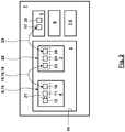
- Fig. 1 1 is a laboratory centrifuge 1 in a centrifugal chamber 2 of the laboratory centrifuge 1 is a rotor 3 driven by a motor, on which a plurality of centrifuge containers 4a, 4b, ... (which are referred to in some embodiments as a "centrifuge cup") held, in particular suspended.
- the laboratory centrifuge 1 points, preferably adjacent to the centrifugation chamber 2, a transmitting and / or receiving device 5.
- the laboratory centrifuge 1 has a control device 6 and an output device 7, which is preferably a display 8.
- the device 9 has at least one antenna 10.
- one antenna can serve for the uni- or bi-directional exchange of information, while another antenna is used for the excitation for the power supply. But it is also possible that the exchange of information and the excitation to the power supply via the same antenna 10 is guaranteed.
- the device 9 has an RFID device 11.
- the device 9 can furthermore have at least one sensor 12 for detecting an operating variable of the centrifuge container 4.
- the antenna 10, the RFID device 11 and the sensor 12 are formed in the usual manner and connected to each other. These may be combined to form a structural unit or arranged distributed and connected to each other via electrical connection lines. It is possible that the RFID device 11 and / or the sensor 12 are arranged on a circuit board 13. It is possible, for example, that the RFID device 11 and / or the sensor 12, in particular on the board 13, with a small distance from a rotation axis of the laboratory centrifuge 1 are arranged so that they are as small as possible Accelerations are exposed.
- the antenna 10 can be positioned freely such that optimal communication with the transmitting and / or receiving device 5 of the laboratory centrifuge 1 results.
- the antenna 10 may be arranged at a location which has the smallest possible distance from the transmitting and / or receiving device 5, to which the antenna 10 is preferably arranged at a small distance from a wall 14 which delimits the centrifugation chamber 2 ,
- the antenna 10 may be arranged at a small distance from a vertical, in particular cylindrical side wall or from the bottom or the lid of the centrifugation chamber 2.
- FIG. 1 dotted an exchange 15 of information and an excitation 16 between the antenna 10 of the device 9 of the centrifuge container 4 and an antenna 17 of the transmitting and / or receiving device 5 are shown.
- a communication 18 between the antennas 10, 17 may consist in the exchange 15 of the information and / or the excitation 16, wherein also an exchange 15 and an excitation 16 can take place simultaneously or the exchange 15 and the excitation 16 alternately and in different phases of operation can be done.
- a laboratory centrifuge 1 After assembly of the centrifuge container 4 with products and suspension of the centrifuge container 4 on the rotor 3, the rotor 3 is used with the centrifuge containers 4 in the centrifugation chamber 2, and it is a drive connection with the drive of the laboratory centrifuge 1 created.
- the device 9 which likewise forms a transmitting and / or receiving device 19, a marking of the associated centrifuge container 4 is stored in a memory unit. This marking may indicate the type of centrifuge container 4 used, with which several centrifuge containers 4 of the same type have the same marking. Alternatively or additionally, it is possible for a marking to be stored in the form of a marking specific to each centrifuge container 4.
- the control software thereof For example, triggered by a manual input of the user of the laboratory centrifuge 1, by closing the lid of the laboratory centrifuge 1 or recording the operation of the laboratory centrifuge 1 by the control software thereof generates a control unit 20 of the transmitting and / or receiving device 5, an excitation 16 for the purpose of energy supply of the transmitter and / or receiving device 19.
- the memory can be read and an exchange 15 of information, here the read-out label done.
- the thus transmitted identifier is then transmitted to the control device 6, which is an evaluation performs. This evaluation may, for example, consist in the test as to whether the type of centrifuge container 4 correlated with the labeling is correct for the laboratory centrifuge 1 or the selected centrifugation process.
- centrifuge containers 4 it is checked whether the right number of centrifuge containers 4 is suspended on the rotor 3.
- the count of a counter of the device 9 by means of which it is counted how many centrifugation processes the centrifuge container 4 has passed through, is read out. If the test indicates that the intended type of centrifuge containers 4 is present and the correct number of centrifuge containers 4 are suspended from the rotor 3 and / or the counter readings of the centrifuge containers 4 are smaller than the maximum number of centrifugation processes which the centrifuge containers 4 are allowed to pass through, done by the control unit 6, the release of the centrifugation process.
- an exchange 15 of information takes place between the transmitting and / or receiving devices 5, 19, in that a counting pulse for carrying out a further centrifuging process is transmitted to the transmitting and / or receiving device 19 of the centrifuge container 4, such that a stored current count of a counter of the means 9 for the number of centrifugation processes to which the centrifuge container 4 was exposed can be increased by one.
- an exchange 15 of information in the form of a currently ascertained or temporarily stored measured value of the sensor 12 to the transmitting and / or receiving device 5 can take place with subsequent processing by the control device 6.
- an exchange 15 of information takes place in the form of the current counter reading.
- the control device 6 compares the current counter reading with a threshold value. Detects the controller 6 based on this comparison that the maximum allowable count is reached, the controller 6 generates an output on the display 8 such that the user is signaled that the centrifuge container 4 has passed through the maximum number of permissible centrifugation processes.
- the control device 6 preferably also generates an output on the display 8, which makes it possible to identify the centrifuge container 4 among the majority of the centrifuge container 4 arranged in the laboratory centrifuge 1, which is done, in particular, by displaying the marking specific to the centrifuge container 4.
- Fig. 2 also shows a schematic diagram of a modified embodiment.
- the RFID device 11 and the sensor 12 are not arranged on a common board 13. Rather, here form the antenna 10 and the RFID device 11, a structural unit 21, while the sensor 12 is formed separately and u. U. also spaced from the assembly 21 is arranged.
- the communication 18 of the transmitting and / or receiving device 19 of the centrifuge container 4 does not take place with the transmitting and / or receiving device 5 of the laboratory centrifuge 1, but rather with a transmitting and / or receiving device 22 of the rotor 3.
- This can, for example have an antenna 23, via which the communication 18 takes place, and a control device 24 for controlling a possible excitation 16 and / or exchange 15.
- the transmitting and / or receiving device 22 of the rotor 3 is in communication 25 with the transmitting and This communication 25 can be wired, for example via a sliding contact between the rotor 3 and the laboratory centrifuge 1, take place.
- the communication 25 but also wirelessly.
- the transmitting and / or receiving device 22 has an antenna 26, via which the communication 25 with the antenna 17 of the transmitting and / or receiving device 5 takes place.
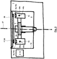
- Fig. 3 shows very schematically the laboratory centrifuge 1 with the rotatably mounted about a rotation axis 27 and driven rotor 3 and about pivot axes 28a, 28b, ... suspended centrifuge containers 4a, 4b, ...
- the devices 9a, 9b, ... im Area of the lid of the centrifuge container 4 is arranged.
- the centrifugation chamber 2 is closed with a cover 29.
- a ring antenna 30 is held on the centrifugation chamber 2 side facing.
- the ring antenna 30 is disposed concentric with the axis of rotation 27 and located at a small distance from the devices 9a, 9b, ... and the antennas 10a, 10b, ... thereof to allow short transmission paths.
- Fig. 4 shows by way of example and highly schematic an electrical circuit diagram of a device 9.
- the antenna 10 is connected via a branch 31 in a first line branch 32 via a first filter 33 to the sensor 12. Furthermore, the antenna 10 is connected via the branch 31 in a second line branch 34 via a second filter 35 to the RFID device 11 connected.
- the first leg 32 has a demodulator 36 (acting in the direction from the antenna 10 to the sensor 12) and a modulator 37 (acting in the direction from the sensor 12 to the antenna 10), the demodulator 36 and the modulator 37 preferably between the filter 33 and the sensor 12 are arranged. It is possible for the demodulator 36 and / or the modulator 37 to have a diode 38 with a downstream low-pass filter or a capacitor.
- the first filter 33 is a high pass while the second filter 35 is a low pass.
- the high pass and the low pass have no overlap in terms of their patency.
- the filters 33, 35 are designed as bandpass filters without overlapping.
- the junction 31 and the filters 33, 35 are formed by a diplexer or a so-called diplexer, at the input of which the antenna 10 is connected and at the outputs of which the sensor 12 and the RFID device 11 are connected.
- the resonant circuit of the sensor 12 forms a vibratory system, wherein the resonant circuit of the sensor 12 is formed with a quartz 39.
- the resonant frequency of the resonant circuit is dependent on the temperature to which the sensor 12 is exposed due to the temperature dependence of the behavior of the quartz 39, whereby the sensor 12 is a temperature sensor.
- the RFID device 11 has a memory 40.
- a specific for the centrifuge container 4 characteristic 41 is stored in the memory 40 .
- the parameter 41 allows a unique identification of the associated centrifuge container 4.
- the parameter 41 may be, for example, a serial number or a serial or product number.
- the parameter 41 is a calibration parameter which can describe the behavior of the sensor 12, in this case the specific dependence of the resonance frequency on the temperature acting on the quartz 39.
- a parameter may be, for example, a calibration factor, a calibration curve, a calibration function or a calibration map.
- a device 9 according to Fig. 4 allows the following operation: If an excitation 16 of the device 9 with an excitation frequency which can pass through the second filter 35, but does not pass the first filter 33, can be a power supply the RFID device 11 are ensured by this excitation, and it can be an exchange 15 of information, here the characteristic 41, take place.
- the resonant circuit formed by the quartz 39 of the sensor 12 has a temperature-dependent resonant frequency.
- the resonant circuit is excited to oscillate at the resonant frequency by means of excitation 16, with a design of the resonant circuit such that, in the expected temperature range, the resonant frequency is in a frequency range which allows excitation in resonance with an excitation frequency of the excitation 16 which is the first Filter 33 can happen, but the second filter 35 does not happen.
- the temperature can be determined by means of the transmitting and / or receiving device 5 or 22 by the variation of the excitation frequency and the search of the resonance via a calibration characteristic which describes the dependence of the resonance frequency on the temperature.
- an excitation 16 may have a carrier frequency in the range of 2.4 GHz to 2.5 GHz, while the resonant frequency of the resonant circuit of the sensor 12 may be, for example, in a range of 32 KHz to 67 KHz or 170 KHz to 250 KHz.
- the RFID device 11 is excited at a frequency of 868 MHz or 915 MHz, whereby changes of ⁇ 5% or ⁇ 10% of these frequencies are also possible. If a plurality of centrifuge containers 4 with associated sensors are used in a laboratory centrifuge 1 or in several laboratory centrifuges 1, the resonant circuits of the sensors 12 can have resonance frequencies in different, non-overlapping resonant frequency ranges.
- an antenna 17 of the laboratory centrifuge can be designed as a cable antenna, for which purpose preferably a so-called locfield antenna ("LOCFIELD" is a registered trademark) can be used with a length in the range of 0.5 m to 1.5 m or 0, 8 meters to 1.2 meters.
- the cable antenna may then be integrated into the cover 29, for which purpose the cover 29 may have a partially annular or annular groove or recess in which the cable antenna extends over a partial circumference or over the entire circumference about the axis of rotation 27 extends.
- a plate antenna is used, which is integrated in particular in a recess of the lid and is preferably covered in the direction of the centrifugation chamber 2 protective and / or sealing.
- the communication with at least one of the aforementioned, integrated in the lid 29 antenna by means of UHF frequencies.
- a transmission of information to the sample container to the control unit 20 of the laboratory centrifuge 1 for example, the type of sample, a type identification of the sample, a specific sample number of the sample, the date of filling the sample container u.
- This information can then be displayed to the user on a display of the laboratory centrifuge 1 or stored by the laboratory centrifuge 1 or externally thereof.
Abstract
Die Erfindung betrifft einen Zentrifugenbehälter (4), der Einsatz findet in einer Laborzentrifuge (1). Erfindungsgemäß weist der Zentrifugenbehälter (4) eine RFID-Einrichtung (11) auf. Die RFID-Einrichtung (11) kann mit der Laborzentrifuge (1) kommunizieren. Diese Kommunikation kann beispielsweise eine Anzahl von Betriebszyklen, die der Zentrifugenbehälter (4) durchlaufen hat, eine Zentrifugationsdauer, eine Winkelgeschwindigkeit einer Rotation des Zentrifugenbehälters (4), eine Beschleunigung des Zentrifugenbehälters (4), ein Ausschwingwinkel des Zentrifugenbehälters (4) und/oder eine Temperatur im Inneren des Zentrifugenbehälters (4) sein. Möglich ist auch, dass der Zentrifugenbehälter (4) über eine Speichereinheit verfügt, in der die von dem Zentrifugenbehälter (4) durchlaufenen Zyklen von Zentrifugationsprozessen gespeichert ist. Auf diese Weise kann eine Erfassung eines Zyklusstandes des Zentrifugenbehälters (4) unabhängig davon erfolgen, mit welcher Laborzentrifuge (1) der Zentrifugenbehälter (4) betrieben wird.The invention relates to a centrifuge container (4), which is used in a laboratory centrifuge (1). According to the invention, the centrifuge container (4) has an RFID device (11). The RFID device (11) can communicate with the laboratory centrifuge (1). This communication can be, for example, a number of operating cycles that the centrifuge container (4) has undergone, a centrifugation time, an angular velocity of a rotation of the centrifuge container (4), an acceleration of the centrifuge container (4), a swing-out angle of the centrifuge container (4) and / or one Temperature inside the centrifuge container (4). It is also possible for the centrifuge container (4) to have a storage unit in which the cycles of centrifugation processes passed through by the centrifuge container (4) are stored. In this way, a cycle status of the centrifuge container (4) can be determined regardless of the laboratory centrifuge (1) with which the centrifuge container (4) is operated.
Description
Die Erfindung betrifft eine Laborzentrifuge. Laborzentrifugen der hier vorliegenden Art finden Einsatz beispielsweise in der Biotechnologie, der pharmazeutischen Industrie, der Medizintechnik und der Umweltanalytik. Mittels einer derartigen Laborzentrifuge erfolgt ein Zentrifugieren eines Produkts, insbesondere eines Behälters oder Gefäßes mit darin angeordneter Probe oder Substanz, oder einer Vielzahl derartiger Produkte mit Drehzahlen, welche mehr als 3.000 U/min, bspw. mehr als 15.000 U/min, betragen können. Infolge der Zentrifugation sollen auf das Produkt wirkende Beschleunigungen erzeugt werden, welche bspw. mehr als 15.000 x g (insbesondere mehr als 16.000 x g, mehr als 20.000 x g bis hin zu mehr als 60.000 x g) betragen können. Durch die Zentrifugation soll ein von der Probe oder der Substanz gebildetes Stoffgemisch in Komponenten unterschiedlicher Dichte zerlegt werden. Je nach den chemischen und/oder physikalischen Eigenschaften des Stoffgemisches kann während der Zentrifugation ergänzend eine gezielte Steuerung der Druck- und/oder Temperaturverhältnisse erfolgen. Um lediglich einige Beispiele zu nennen, kann der Einsatz einer Laborzentrifuge im Zusammenhang mit einer Polymerase-Kettenreaktion (PCR), einer Bestimmung des Hematokrits, zytologischen Untersuchungen oder dem Zentrifugieren von Mikrotitern, Blutbeuteln, Erdölgefäßen oder Blutgefäßen u. ä. erfolgen.The invention relates to a laboratory centrifuge. Laboratory centrifuges of the present type are used, for example, in biotechnology, the pharmaceutical industry, medical technology and environmental analysis. By means of such a laboratory centrifuge is carried out a centrifugation of a product, in particular a container or vessel with a sample or substance arranged therein, or a plurality of such products at speeds which may be more than 3,000 U / min, for example. More than 15,000 U / min. As a result of the centrifugation, accelerations acting on the product are to be produced, which may be, for example, more than 15,000 × g (in particular more than 16,000 × g, more than 20,000 × g up to more than 60,000 × g). The centrifugation is intended to break down a mixture of substances formed by the sample or the substance into components of different densities. Depending on the chemical and / or physical properties of the substance mixture, a targeted control of the pressure and / or temperature conditions can additionally take place during the centrifugation. To mention just a few examples, the use of a laboratory centrifuge in connection with a polymerase chain reaction (PCR), a determination of the hematocrit, cytological examinations or the centrifuging of microtitres, blood bags, petroleum vessels or blood vessels u. Ä.
In Laborzentrifugen der hier vorliegenden Art können unterschiedliche Rotortypen, insbesondere Ausschwingrotoren, Winkelrotoren oder Trommelrotoren, Einsatz finden, wobei vorzugsweise in einer erfindungsgemäßen Laborzentrifuge ein Ausschwingrotor Einsatz findet, an welchem Zentrifugenhälter über den Umfang gleichmäßig verteilt angeordnet sind und verschwenkbar um eine in Umfangsrichtung orientierte Schwenkachse gehalten sind. Derartige Ausschwingrotoren sind beispielsweise einsetzbar für eine Sedimentation für kleinere Schwerefelder bis zu ca. 6.000 x g oder sogar bis hin zu ca. 8.600 x g, was beispielsweise für die Medizin oder die Forschung der Fall sein kann.In laboratory centrifuges of the present type, different types of rotors, in particular swinging bucket rotors, angle rotors or drum rotors, find use, preferably in a laboratory centrifuge according to the invention a swinging bucket rotor is used, are arranged on which centrifuge containers distributed evenly over the circumference and pivotally supported about a circumferentially oriented pivot axis are. Such swinging bucket rotors For example, they can be used for sedimentation of smaller gravitational fields up to approx. 6,000 xg or even up to approx. 8,600 xg, which may be the case for example in medicine or research.
Des Weiteren betrifft die Erfindung einen Zentrifugenbehälter, welcher insbesondere für einen Ausschwingrotor bestimmt ist. Schließlich betrifft die Erfindung auch ein Verfahren zum Betrieb eines Zentrifugenbehälters.Furthermore, the invention relates to a centrifuge container, which is intended in particular for a swing-bucket rotor. Finally, the invention also relates to a method for operating a centrifuge container.
Der vorliegenden Erfindung liegt die Aufgabe zugrunde, einen Zentrifugenbehälter und eine Laborzentrifuge vorzuschlagen, welcher oder welche insbesondere hinsichtlich
- der Betriebssicherheit,
- einer Überwachung der Bestückung eines Rotors,
- einer Aufnahme und Übertragung von Messsignalen,
- einer Überwachung der Zahl der Einsatzzyklen eines Zentrifugenbehälters und/oder
- der Gewährleistung der Betriebsfestigkeit
- the operational safety,
- a monitoring of the assembly of a rotor,
- a recording and transmission of measurement signals,
- monitoring the number of use cycles of a centrifuge container and / or
- Ensuring the durability
Die Aufgabe der Erfindung wird erfindungsgemäß mit den Merkmalen der unabhängigen Patentansprüche gelöst. Weitere bevorzugte erfindungsgemäße Ausgestaltungen sind den abhängigen Patentansprüchen zu entnehmen.The object of the invention is achieved with the features of the independent claims. Further preferred embodiments according to the invention can be found in the dependent claims.
Die der Erfindung zugrundeliegende Aufgabe wird gelöst mittels eines Zentrifugenbehälters für eine Laborzentrifuge, der eine RFID-Einrichtung (oder eine Einrichtung mit einer RFID-Einrichtung) aufweist. RFID-Einrichtungen mit der erforderlichen Qualität können inzwischen zu vertretbaren Preisen bereitgestellt werden. Die RFID-Einrichtung ermöglicht drahtlos eine Energieversorgung und/oder einen Austausch von Informationen zwischen dem Zentrifugenbehälter und benachbarten Bauelementen wie einem Rotor der Laborzentrifuge oder der Laborzentrifuge selbst.The object underlying the invention is achieved by means of a centrifuge container for a laboratory centrifuge which has an RFID device (or a device with an RFID device). Meanwhile, RFID devices with the required quality can be added too reasonable prices. The RFID device wirelessly provides power and / or information exchange between the centrifuge container and adjacent components such as a laboratory centrifuge rotor or the laboratory centrifuge itself.
Für im Rahmen der Erfindung austauschbare Informationen gibt es vielfältige Möglichkeiten, von denen im Folgenden lediglich einige Beispiele genannt werden, ohne dass eine Einschränkung der Erfindung auf die Beispiele erfolgen soll:
- 1. Es kann sich bei den Informationen um eine Kennzeichnung des Zentrifugenbehälters handeln, welche in einer Speichereinheit der RFID-Einrichtung gespeichert ist. Eine Kennzeichnung der RFID-Einrichtung und damit des zugeordneten Zentrifugenbehälters kann spezifisch für den jeweiligen Zentrifugenbehälter sein oder aber spezifisch für einen Typ des Zentrifugenbehälters sein. Wird ein Zentrifugenbehälter mit einem Rotor in die Laborzentrifuge eingesetzt, kann eine Anregung der RFID-Einrichtung erfolgen und ein Auslesen der Kennzeichnung des Zentrifugenbehälters erfolgen, so dass bekannt ist, ob ein Zentrifugenbehälter und ggf. welcher spezifische Zentrifugenbehälter oder welcher Typ von Zentrifugenbehälter in dem Rotor und der Laborzentrifuge eingesetzt ist.
- 2. Alternativ oder zusätzlich möglich ist, dass es sich bei den Informationen um Betriebsdaten des Zentrifugenbehälters (und damit der in dem Zentrufgenbehälter angeordneten Produkte) handelt.
- a) Betriebsdaten können beispielsweise in der RFID-Einrichtung gespeicherte Informationen zu dem mindestens einen Produkt oder dem Zentrifugenbehälter, wie beispielsweise ein Herstellungsdatum der Probe oder des Zentrifugenbehälters, ein Datum der Anordnung des Produkts in dem Zentrifugenbehälter, eine Spezifizierung der Probe oder des Zentrifugenbehälters, eine maximal zulässige Temperatur der Probe oder des Zentrifugenbehälters, eine Kompensationsabhängigkeit wie eine Kompensationskurve, welche die Abhängigkeit der Temperatur der Probe oder des Zentrifugenbehälters von einer gemessenen Temperatur in einem Innenraum der Zentrifugationskammer beschreibt, u. ä., sein.
- b) Um lediglich einige weitere nicht beschränkende Beispiele für Betriebsdaten zu nennen, kann die RFID-Einrichtung des Zentrifugenbehälters Informationen über den gewünschten bestimmungsgemäßen Prozess des Zentrifugierens, wie beispielsweise eine Dauer des Zentrifugierens, ein Drehzahlverlauf oder eine maximale Drehzahl während des Zentrifugierens, eine maximale Winkelbeschleunigung oder eine maximal auf die Probe wirkende Zentrifugalbeschleunigung u. ä., enthalten, welche dann von der Laborzentrifuge ausgelesen werden und dann von einer Prozesssteuerung der Laborzentrifuge verarbeitet und für die Steuerung oder Regelung der Durchführung der Zentrifugation berücksichtigt werden.
Möglich ist aber auch, dass die vorgenannten Betriebsdaten während des Zentrifugationsprozesses über Sensoren erfasst und dokumentiert werden, so dass diese von der Laborzentrifuge während der Zentrifugation ausgelesen werden können zur Überwachung und/oder Dokumentation des Zentrifugationsprozesses oder auch zu einem späteren Zeitpunkt zwecks Dokumentation und/oder weiterer Auswertung außerhalb der Laborzentrifuge ausgelesen werden können
Ebenfalls möglich ist, dass die Betriebsdaten Messsignale eines Sensors des Zentrifugenbehälters sind, welche vor, während oder nach der Zentrifugation aufgenommen werden und (ohne oder mit Speicherung) dann ausgetauscht werden können. Um lediglich einige nicht beschränkende Beispiele zu nennen, kann es sich um Messsignale- eines Beschleunigungssensors für eine Winkelbeschleunigung oder die Zentrifugalbeschleunigung des Zentrifugenbehälters,
- eines Drehzahlsensors des Zentrifugenbehälters,
- eines Winkelgeschwindigkeitssensors des Zentrifugenbehälters,
- eines Neigungssensors für die Erfassung der Neigung des Zentrifugenbehälters bei Einsatz in einem Ausschwingrotor,
- eines Temperatursensors des Zentrifugenbehälters, der vorzugsweise die Temperatur im Inneren des Zentrifugenbehälters und/oder die Temperatur außerhalb des Zentrifugenbehälters und damit in der Zentrifugationskammer misst,
- eines Sensors zur Erfassung der Dauer und/oder des Ausmaßes der Zentrifugation des Zentrifugenbehälters und/oder
- eines Sensors, der die Zusammensetzung des Gases in dem Zentrifugenbehälter oder außerhalb desselben, insbesondere in der Zentrifugationskammer, misst, um beispielsweise zu überwachen, dass inerte Bedingungen, insbesondere in Form von die Proben umgebendem reinem Sauerstoff oder Stickstoff, vorliegen
- 3. Alternativ oder kumulativ möglich ist, dass die Informationen Prozessinformationen (insbesondere eine Kennzeichnung eines eingesetzten vorbestimmten Zentrifugationsprofils, eine Zentrifugationsdrehzahl und/oder-dauer, ein Drehzahlverlauf, eine erzeugte Zentrifugalbeschleunigung, ein Datum und/oder eine Uhrzeit des durchgeführten Zentrifugationsprozesses u. ä.) sind, welche von der Laborzentrifuge an die RFID-Einrichtung übertragen werden und zwecks Dokumentation in der Einrichtung des Zentrifugenbehälters gespeichert werden. Um lediglich einige die Erfindung nicht beschränkende Beispiele zu nennen, können in einem Zentrifugenbehälter Blutbeutel angeordnet sein. In diesem Fall können die Prozessinformationen eine minimale, maximale oder durchschnittliche Temperatur sein, welcher der Zentrifugenbehälter oder der Blutbeutel ausgesetzt ist. Als weitere Prozessinformationen kann eine durchschnittliche, maximale, minimale oder integrierte Beschleunigung dienen.
- 1. The information may be an identification of the centrifuge container, which is stored in a memory unit of the RFID device. An identification of the RFID device and thus of the associated centrifuge container may be specific to the respective centrifuge container or may be specific to one type of centrifuge container. If a centrifuge container with a rotor is inserted into the laboratory centrifuge, an excitation of the RFID device can take place and a readout of the labeling of the centrifuge container can take place, so that it is known whether a centrifuge container and, if appropriate, which specific centrifuge container or type of centrifuge container in the rotor and the laboratory centrifuge is inserted.
- 2. Alternatively or additionally, it is possible that the information is the operating data of the centrifuge container (and thus the products arranged in the centrifuge container).
- a) Operating data may, for example, information stored in the RFID device to the at least one product or the centrifuge container, such as a date of manufacture of the sample or centrifuge container, a date of placement of the product in the centrifuge container, a specification of the sample or the centrifuge container, a maximum permissible temperature of the sample or of the centrifuge container, a compensation dependence such as a compensation curve, which describes the dependence of the temperature of the sample or of the centrifuge container on a measured temperature in an interior of the centrifugation chamber, u. Ä., be.
- b) To name just a few more non-limiting examples of operating data, the RFID device of the centrifuge container may contain information about the desired centrifuge process, such as a duration of centrifugation, a speed history, or a maximum speed during centrifugation, a maximum angular acceleration or a maximum acting on the sample centrifugal acceleration u. Ä., Which are then read by the laboratory centrifuge and then processed by a process control of the laboratory centrifuge and taken into account for the control or regulation of the execution of the centrifugation.
It is also possible, however, for the abovementioned operating data to be recorded and documented by sensors during the centrifuging process, so that they can be read out from the laboratory centrifuge during centrifugation for monitoring and / or documentation of the centrifugation process or at a later time for the purpose of documentation and / or further evaluation outside the laboratory centrifuge can be read
It is also possible that the operating data are measurement signals of a sensor of the centrifuge container, which are recorded before, during or after the centrifugation and can then be replaced (without or with storage). To name just a few non-limiting examples, these may be measurement signals- an acceleration sensor for an angular acceleration or the centrifugal acceleration of the centrifuge container,
- a speed sensor of the centrifuge container,
- an angular velocity sensor of the centrifuge container,
- an inclination sensor for detecting the inclination of the centrifuge container when used in a swing-bucket rotor,
- a temperature sensor of the centrifuge container, which preferably measures the temperature inside the centrifuge container and / or the temperature outside the centrifuge container and thus in the centrifugation chamber,
- a sensor for detecting the duration and / or extent of centrifugation of the centrifuge container and / or
- a sensor which measures the composition of the gas in or outside the centrifuge container, particularly in the centrifugation chamber, to monitor, for example, that there are inert conditions, particularly in the form of pure oxygen or nitrogen surrounding the samples
- 3. Alternatively or cumulatively, it is possible for the information to include process information (in particular an identification of a predetermined centrifugation profile used, a centrifugation speed and / or duration, a speed curve, a generated centrifugal acceleration, a date and / or time of the centrifugation process carried out, and the like). ) which are transferred from the laboratory centrifuge to the RFID device and stored for documentation in the centrifuge container device. To name just a few non-limiting examples of the invention, blood bags may be placed in a centrifuge container. In this case, the process information may be a minimum, maximum, or average temperature to which the centrifuge container or blood bag is exposed. Further process information may be average, maximum, minimum or integrated acceleration.
Hinsichtlich der grundsätzlichen Ausgestaltung, möglichen Bauformen, Komponenten und der Anregung sowie Kommunikation von und mit im Rahmen der Erfindung einsetzbaren RFID-Einrichtungen wird grundsätzlich auf die Website www.wikipedia.de unter dem Suchbegriff RFID und RFID-Einrichtungen betreffende Standardwerke und Veröffentlichungen, insbesondere
verwiesen.With regard to the basic design, possible designs, components and the excitation as well as communication from and with usable within the scope of the invention RFID devices is basically on the website www.wikipedia.de under the search term RFID and RFID devices relevant standard works and publications, in particular
directed.
Eine weitere Ausgestaltung der Erfindung widmet sich dem Spannungsfeld des Einsatzes einer RFID-Einrichtung in einem Zentrifugenbehälter für eine Laborzentrifuge:
- a) Einerseits ist für eine drahtlose Anregung der Einrichtung zur Leistungsversorgung derselben und andererseits für den (uni-direktionalen oder bi-direktionalen) Austausch von Informationen zwischen der Einrichtung und benachbarten Bauelementen, insbesondere des Rotors und/oder der Laborzentrifuge, erforderlich, dass die Einrichtung und insbesondere eine Antenne derselben nicht durch den Zentrifugenbehälter, den Rotor oder andere Bauelemente abgeschirmt ist, womit die Anregung und der Austausch von Informationen zumindest erschwert würde.
- b) Des Weiteren haben Untersuchungen gezeigt, dass infolge der hohen, in Laborzentrifugen eingesetzten Drehzahlen und dadurch hervorgerufenen Zentripetalbeschleunigungen Bauelemente der Einrichtung Schaden nehmen können.
- c) Möglich ist auch, dass eine Anregung und/oder ein Austausch von Informationen nur möglich sind/ist, wenn die Relativgeschwindigkeit zwischen der Einrichtung des Zentrifugenbehälters gegenüber einer Sende- und/oder Empfangseinrichtung der Laborzentrifuge, durch welche die Anregung erfolgt und/oder Informationen gesendet und/oder empfangen werden, einen Schwellwert nicht überschreitet. So sind beispielsweise in der Literaturstelle
"Prüftechnik für RFID bei Hochgeschwindigkeitsanwendungen im Transportwesen", Mathias Baum, Björn Niemann, Ludger Overmeyer, Institut für Transport- und Automatisierungstechnik (ITA), Universität Hannover, ISBN 1860-5923
Sende- und/oder Empfangseinrichtungen und zugeordnete RFID-Einrichtungen eingesetzt worden, welche nur biszu Relativgeschwindigkeiten von 11,5 m/s arbeitsfähig waren. Für eine Rotation des Rotors der Laborzentrifuge mit einer Drehzahl von 6.000 U/min hat dies zur Folge, dass die Einrichtung, insbesondere die Antenne derselben, einen maximalenAbstand von 1,8 cm von der Rotationsachse des Rotors aufweisen darf, wenn die Sende- und/oder Empfangseinrichtung gehäusefest angeordnet ist und somit nicht mit dem Rotor rotiert. - d) Angesichts der in der Laborzentrifuge wirkenden hohen Beschleunigungen kann eine Lösung der Einrichtung von dem Zentrifugenbehälter im Betrieb der Laborzentrifuge zu beträchtlichen Schäden an der Laborzentrifuge und Bauelementen derselben führen.
- a) On the one hand, for a wireless excitation of the device for supplying power thereto and, on the other hand, for the (unidirectional or bi-directional) exchange of information between the device and neighboring components, in particular the rotor and / or the laboratory centrifuge, it is necessary for the device and in particular an antenna thereof is not shielded by the centrifuge container, the rotor or other components, whereby the excitation and the exchange of information would at least made more difficult.
- b) Furthermore, studies have shown that components of the device can be damaged as a result of the high rotational speeds used in laboratory centrifuges and the resulting centripetal accelerations.
- c) It is also possible that excitation and / or exchange of information is / are only possible if the relative speed between the device of the centrifuge container with respect to a transmitting and / or receiving device of the laboratory centrifuge, through which the excitation takes place and / or information sent and / or received, does not exceed a threshold. For example, in the literature
"Testing technology for RFID in high-speed applications in transportation ", Mathias Baum, Bjorn Niemann, Ludger Overmeyer, Institute for Transport and Automation Technology (ITA), University of Hannover, ISBN 1860-5923
Transmitting and / or receiving devices and associated RFID devices have been used, which were only able to operate relative speeds of 11.5 m / s. For a rotation of the rotor of the laboratory centrifuge with a speed of 6,000 rpm, this means that the device, in particular the antenna of the same, may have a maximum distance of 1.8 cm from the axis of rotation of the rotor when the transmitting and / or receiving device is fixed to the housing and thus does not rotate with the rotor. - d) In view of the high accelerations acting in the laboratory centrifuge, solution of the device from the centrifuge container during operation of the laboratory centrifuge can lead to considerable damage to the laboratory centrifuge and its components.
Diesem Spannungsfeld trägt die Erfindung für eine Ausführungsform dadurch Rechnung, dass ein Kopplungsbereich für eine Kopplung des Zentrifugenbehälters mit einem Rotor vorhanden ist, der eine Ausrichtung des Zentrifugenbehälters gegenüber einer Rotationsachse des Rotors vorgibt. Für den Fall, dass der Zentrifugenbehälter Einsatz findet mit einem Ausschwingrotor, kann sich die Ausrichtung des Zentrifugenbehälters gegenüber dem Rotor zwar noch um die in Umfangsrichtung orientierte Schwenkachse ändern. Der Kopplungsbereich gibt in diesem Fall aber vor, welche Seite des Zentrifugenbehälters auf der der Rotationsachse des Rotors zugewandten Seite angeordnet ist und welche Seite des Zentrifugenbehälters auf der gegenüberliegenden Seite angeordnet ist, welche benachbart der Wandung der Laborzentrifuge angeordnet ist, die die Zentrifugationskammer der Laborzentrifuge begrenzt. Für diese Ausgestaltung ist die Einrichtung (oder ein Teil derselben wie beispielsweise eine Platine mit den elektronischen Bauelementen ausschließlich der Antenne) auf der Seite des Zentrifugenbehälters angeordnet, welche in dem Zustand, in dem der Zentrifugenbehälter mit dem Rotor gekoppelt ist, der Rotationsachse zugewandt ist. Dies hat zur Folge, dass die Einrichtung (oder das Teil derselben) einen kleinen Abstand von der Rotationsachse hat, womit dann die auf die Einrichtung oder die Teile derselben wirkenden Beschleunigungskräfte klein sind, womit einerseits die Arbeitsfähigkeit der Einrichtung hin zu größeren Drehzahlen erweitert wird und/oder mechanische oder elektronische Beeinträchtigungen der Einrichtung vermieden werden können.For one embodiment, this field of tension is taken into account by the invention in that there is a coupling region for a coupling of the centrifuge container to a rotor which predetermines an alignment of the centrifuge container with respect to a rotational axis of the rotor. In the event that the centrifuge container is used with a swing-bucket rotor, the orientation of the centrifuge container relative to the rotor may still change around the pivot axis oriented in the circumferential direction. In this case, however, the coupling region specifies which side of the centrifuge container is arranged on the side facing the axis of rotation of the rotor and which side of the centrifuge container is arranged on the opposite side, which is arranged adjacent to the wall of the laboratory centrifuge which delimits the centrifugation chamber of the laboratory centrifuge , For this embodiment, the device (or a part thereof such as a circuit board with the electronic components excluding the antenna) on the side of the centrifuge container is arranged, which faces the axis of rotation in the state in which the centrifuge container is coupled to the rotor. This has the consequence that the device (or the part of the same) has a small distance from the axis of rotation, which then the force acting on the device or parts of the same acceleration forces are small, on the one hand, the working capacity of the device is extended to higher speeds and / or mechanical or electronic impairments of the device can be avoided.
Für eine weitere Ausgestaltung ist eine Antenne der Einrichtung auf der Seite des Zentrifugenbehälters angeordnet, welche in dem Zustand, in dem der Zentrifugenbehälter mit dem Rotor gekoppelt ist, der Rotationsachse abgewandt ist. Weitere Komponenten der Einrichtung sind in diesem Fall auf der Seite des Zentrifugenbehälters angeordnet, welche der Rotationsachse zugewandt ist. Somit sind Komponenten der Einrichtung auf unterschiedlichen Seiten des Zentrifugenbehälters angeordnet und dabei vorzugsweise elektrisch miteinander gekoppelt. Dieser Lösungsgedanke gewährleistet, dass keine Abschirmung der Antenne der Einrichtung durch den Zentrifugenbehälter gegenüber einer Sende- und/oder Empfangseinrichtung erfolgt, die im Bereich der Wandung der Laborzentrifuge, die die Zentrifugationskammer der Laborzentrifuge begrenzt, angeordnet ist. Hierbei wird in Kauf genommen, dass die Antenne der Einrichtung infolge des verhältnismäßig großen Abstandes von der Rotationsachse verhältnismäßig großen Beschleunigungen ausgesetzt ist. Weitere Komponenten der Einrichtung, die dann auf der der Rotationsachse zugewandten Seite angeordnet sind, werden aber mit kleineren Beschleunigungen beansprucht, was beispielsweise vorteilhaft für sensible elektrische oder elektronische Komponenten wie eine elektronische Steuereinheit oder die RFID-Einrichtung und/oder einen Sensor der Fall sein kann.For a further embodiment, an antenna of the device is arranged on the side of the centrifuge container, which in the state in which the centrifuge container is coupled to the rotor, faces away from the axis of rotation. Other components of the device are arranged in this case on the side of the centrifuge container, which faces the axis of rotation. Thus, components of the device are arranged on different sides of the centrifuge container and thereby preferably electrically coupled to each other. This solution ensures that no shielding of the antenna of the device by the centrifuge container with respect to a transmitting and / or receiving device, which is located in the region of the wall of the laboratory centrifuge, which limits the centrifugation chamber of the laboratory centrifuge. It is accepted that the antenna of the device due to the relatively large distance from the axis of rotation relatively is exposed to large accelerations. Other components of the device, which are then arranged on the axis of rotation facing side, but are claimed with smaller accelerations, which may be advantageous for example for sensitive electrical or electronic components such as an electronic control unit or the RFID device and / or a sensor ,
Für eine andere Ausgestaltung des erfindungsgemäßen Zentrifugenbehälters ist ebenfalls ein Kopplungsbereich für eine Kopplung des Zentrifugenbehälters mit einem Rotor vorhanden, der eine Ausrichtung des Zentrifugenbehälters gegenüber einer Rotationsachse des Rotors vorgibt. In diesem Fall ist die Antenne der Einrichtung (oder sogar die gesamt Einrichtung) auf der Seite des Zentrifugenbehälters angeordnet, welche in dem mit dem Rotor gekoppelten Zustand des Zentrifugenbehälters dem Deckel oder dem Boden der Laborzentrifuge zugewandt ist, was vorzugsweise mit einem kleinen Abstand von der Rotationsachse erfolgt. In diesem Fall kann die Antenne der Einrichtung angeregt werden und/oder in Austausch von Informationen stehen mit einer Sende- und/oder Empfangseinrichtung, deren Antenne im Bereich des Bodens oder des Deckels der Laborzentrifuge angeordnet ist.For another embodiment of the centrifuge container according to the invention is also a coupling region for a coupling of the centrifuge container with a rotor present, which specifies an orientation of the centrifuge container with respect to a rotational axis of the rotor. In this case, the antenna of the device (or even the entire device) is arranged on the side of the centrifuge container, which faces the lid or the bottom of the laboratory centrifuge in the coupled with the rotor state of the centrifuge container, which is preferably at a small distance from the Rotation axis takes place. In this case, the antenna of the device can be excited and / or in exchange of information with a transmitting and / or receiving device whose antenna is arranged in the region of the bottom or the lid of the laboratory centrifuge.
Für einen Vorschlag der Erfindung weist die Einrichtung eine Antenne auf, über die die Einrichtung drahtlos von einer Energiequelle mit Energie versorgt werden kann, die außerhalb des Zentrifugenbehälters angeordnet ist. Diese Energiequelle kann eine eine Anregung gewährleistende Sendeeinrichtung sein, welche mit dem Rotor verdreht wird oder gehäusefest an der Laborzentrifuge angeordnet ist und beispielsweise im Bereich einer eine Zentrifugationskammer begrenzenden Wandung oder sogar im Innenraum der Zentrifugationskammer angeordnet ist.For a proposal of the invention, the device comprises an antenna, by means of which the device can be supplied with energy wirelessly from a power source which is arranged outside the centrifuge container. This energy source can be an excitation ensuring transmitting device which is rotated with the rotor or fixed to the housing is arranged on the laboratory centrifuge and, for example, in the region of a centrifugation chamber bounding wall or even in the interior of the centrifugation chamber is arranged.
Für einen weiteren Vorschlag der Erfindung weist der Zentrifugenbehälter mindestens einen Sensor zur Erfassung einer Betriebsgröße auf. Hierbei kann der Sensor separat von der RFID-Einrichtung oder einer diese ausbildenden Platine ausgebildet sein, aber das Messsignal des Sensors über eine elektrische Messsignalleitung der Platine oder der RFID-Einrichtung zugeführt werden. Ebenfalls möglich ist, dass der Sensor in die RFID-Einrichtung integriert ist oder auf einer die RFID-Einrichtung ausbildenden oder tragenden Platine oder einer anderweitigen Trägereinrichtung, die auch flexibel sein kann, angeordnet ist. Die erfasste Betriebsgröße kann dann von der Einrichtung gespeichert werden oder als Information an benachbarte Bauelemente kommuniziert werden. Hierbei kann von dem Messsignal des Sensors bspw.
- lediglich ein einzelner Wert, ein Mittelwert, ein Maximalwert, ein Minimalwert, ein Wert nach einer vorgegebenen Zeitspanne oder ein Wert zu einem vorgegebenen Prozesszeitpunkt des Zentrifugationsprozesses,
- eine Änderung des Messsignals,
- ein Verlauf des Messsignals oder einer Änderung desselben
- only a single value, an average value, a maximum value, a minimum value, a value after a predetermined period of time or a value at a predetermined process time of the centrifugation process,
- a change of the measuring signal,
- a course of the measuring signal or a change of the same
Für die Betriebsgrößen, welche der Sensor erfasst, gibt es vielfältige Möglichkeiten. Beispielsweise kann ein Sensor die Anzahl der Betriebszyklen zählen, welche der Zentrifugenbehälter durchlaufen hat. Auf diese Weise kann in der Einrichtung und über ein Auslesen der Anzahl der Betriebszyklen dokumentiert und überprüft werden, wie viele Betriebszyklen der Zentrifugenbehälter durchlaufen hat, so dass mit einem Erreichen einer vorgegebenen Anzahl der Betriebszyklen ein Austausch des Zentrifugenbehälters möglich ist. Möglich ist hierbei, dass die Anzahl der Betriebszyklen anhand von Messsignalen während der Zentrifugation, insbesondere Beschleunigungsverläufen oder einem Erreichen eines Maximums oder des Erkennens eines Abbrems- und/oder Beschleunigungsvorgangs der Laborzentrifuge anhand eines geeigneten Sensors des Zentrifugenbehälters erkannt wird. Möglich ist aber auch, dass über eine Sende- und/oder Empfangseinrichtung der Laborzentrifuge mit dem Einsetzen des Zentrifugenbehälters mit einem Rotor in die Laborzentrifuge ein Zählimpuls an die RFID-Einrichtung gesendet wird, welcher die aktuelle Zahl des Zählers um 1 erhöht. Alternativ oder kumulativ möglich ist, dass die Laborzentrifuge einen Zählimpuls an die RFID-Einrichtung sendet, wenn ein Deckel der Laborzentrifuge geschlossen wird oder ein Zentrifugationsprozess begonnen und/oder beendet wird und bspw. ein Schwellwert der Drehzahl des Rotors überschritten wird. Beispielsweise kann es vorteilhaft sein, wenn kein Zählimpuls an die RFID-Einrichtung gesendet und dieser von der RFID-Einrichtung verarbeitet wird, wenn lediglich ein Zentrifugenbehälter in die Laborzentrifuge eingesetzt wird und dieser wieder aus der Laborzentrifuge entnommen wird, ohne dass eine Zentrifugation erfolgt ist.For the operating variables, which the sensor detects, there are many possibilities. For example, a sensor may count the number of operating cycles that the centrifuge container has undergone. In this way, it is possible to document and check in the device and via a readout of the number of operating cycles how many operating cycles the centrifuge container has undergone, so that an exchange of the centrifuge container is possible when a predetermined number of operating cycles has been reached. It is possible here that the number of operating cycles is detected on the basis of measurement signals during centrifugation, in particular acceleration courses or when a maximum or recognition of a deceleration and / or acceleration process of the laboratory centrifuge is detected by means of a suitable sensor of the centrifuge container. But it is also possible that a counting pulse is sent to the RFID device via a transmitting and / or receiving device of the laboratory centrifuge with the insertion of the centrifuge container with a rotor in the laboratory centrifuge, which increases the current number of the counter by 1. Alternatively or cumulatively, it is possible that the laboratory centrifuge sends a count pulse to the RFID device when a lid of the laboratory centrifuge is closed or a centrifugation process is started and / or terminated and, for example, a threshold value of the rotational speed of the rotor is exceeded. For example, it may be advantageous if no counting pulse sent to the RFID device and this is processed by the RFID device when only a centrifuge container is inserted into the laboratory centrifuge and this is removed again from the laboratory centrifuge without centrifugation has taken place.
Möglich ist auch, dass der Zentrifugenbehälter oder die RFID-Einrichtung eine Speichereinheit aufweist, welche eine Speicherung mindestens einer Betriebsgröße ermöglicht. Hierbei kann eine Speicherung einer beliebigen Betriebsgröße, vgl. die zuvor genannten Betriebsgrößen, in der Speichereinheit erfolgen. Um lediglich ein die Erfindung nicht beschränkendes Beispiel zu nennen, kann in der Speichereinheit ein Zykluszählerstand gespeichert werden, der angibt, wie viele Zentrifugationszyklen der mit der Speichereinheit ausgestattete Zentrifugenbehälter bereits durchlaufen hat. Das Zählen der Zyklen kann dabei durch den Zentrifugenbehälter selbst erfolgen, indem beispielsweise anhand eines Beschleunigungssensors des Zentrifugenbehälters mit dem Überschreiten eines Schwellwerts detektiert wird, wenn ein Zentrifugationsprozess durchlaufen wird, so dass mit dem Überschreiten des Schwellwerts ein Zykluszählerstand erhöht wird. Ebenfalls möglich ist, dass ein Impuls zur Veränderung des gespeicherten Zykluszählerstands des Zentrifugenbehälters von der Laborzentrifuge ausgelöst wird und dieser Impuls dann an den Zentrifugenbehälter übermittelt wird, wo dann der in der Speichereinheit gespeicherte Zykluszählerstand um eins erhöht werden kann. Hierbei kann beispielsweise die Laborzentrifuge mit dem Schließen eines Deckels oder auch mit der Initiierung oder dem Durchlaufen eines Zentrifugationsprozesses, beispielswiese einem Überschreiten eines Schwellwerts einer Drehzahl des Rotors, einen Impuls auslösen.It is also possible that the centrifuge container or the RFID device has a memory unit which allows storage of at least one operating variable. In this case, a storage of any operating variable, cf. the aforementioned operating variables take place in the storage unit. For the sake of example only, an example not limiting the invention can be stored in the memory unit, a cycle counter reading that indicates how many cycles of centrifugation of the storage unit equipped with the centrifuge container has already passed. The counting of the cycles can be carried out by the centrifuge container itself, for example, by detecting an acceleration sensor of the centrifuge container with the exceeding of a threshold value when a centrifugation process is run through, so that when the threshold value is exceeded, a cycle count is increased. It is also possible that a pulse for changing the stored cycle count of the centrifuge container is triggered by the laboratory centrifuge and this pulse is then transmitted to the centrifuge container, where then the stored in the memory unit cycle count can be increased by one. Here, for example, the laboratory centrifuge with the closing of a lid or with the initiation or the passage of a centrifugation process, for example, exceeding a threshold value of a rotational speed of the rotor, trigger a pulse.
Um lediglich ein die Erfindung nicht beschränkendes Beispiel zu nennen, kann die erfindungsgemäße Ausgestaltung einen Beitrag zur Behandlung der folgenden Problematik liefern: Für aus dem Stand der Technik bekannte Laborzentrifugen erfolgt eine Zählung der Zentrifugationsprozesse durch die Laborzentrifuge unter der Annahme, dass immer dieselben Zentrifugenbehälter in der Laborzentrifuge verwendet werden. Überschreitet die Zahl der gezählten Zentrifugationsprozesse einen Schwellwert, wird dem Benutzer signalisiert, dass die Zentrifugenbehälter auszutauschen sind oder es erfolgt sogar die Stilllegung der Laborzentrifuge. Eine derartige Überwachung der Zahl der Zentrifugationsprozesse, die ein Zentrifugenbehälter durchlaufen hat, versagt, wenn mit der Laborzentrifuge für unterschiedliche Zentrifugationsprozesse unterschiedliche Zentrifugenbehälter verwendet werden oder ein Zentrifugenbehälter in unterschiedlichen Laborzentrifugen eingesetzt wird. Des Weiteren kann bei einer derartigen bekannten Laborzentrifuge nicht automatisch erkannt werden, wenn (u. U. infolge der signalisierten Notwendigkeit des Austausches der Zentrifugenbehälter) tatsächlich ein Austausch der Zentrifugenbehälter erfolgt ist. Vielmehr ist in diesem Fall eine Art Reset der Laborzentrifuge erforderlich, mit welchem ein Zählstand wieder zurückgesetzt wird und der erneuten Betrieb der Laborzentrifuge ermöglicht wird. Erfindungsgemäß kann durch die RFID-Einrichtung für jeden Zentrifugenbehälter selbst die Zahl der durchlaufenden Zentrifugationsprozesse gezählt werden, womit dann eine Verwendung beliebiger Zentrifugenbehälter mit einer Laborzentrifuge möglich ist und eine spezifische Anzeige und Überwachung der Zahl der durchlaufenden Zentrifugationsprozesse des jeweiligen Zentrifugenbehälters möglich ist. Auch möglich ist, dass auf automatische Weise von der Laborzentrifuge erkannt werden kann, ob die jeweils in der Laborzentrifuge angeordneten Zentrifugenbehälter eine Zahl von Zentrifugationsprozessen durchlaufen hat, die kleiner ist als ein vorgegebener, die Betriebssicherheit gewährleistender Schwellwert.In order to name only an example which does not limit the invention, the embodiment according to the invention can contribute to the treatment of the following problem: For laboratory centrifuges known from the prior art, the centrifugation processes are counted by the laboratory centrifuge, assuming that always the same centrifuge containers in the Laboratory centrifuge can be used. If the number of centrifugation processes counted exceeds a threshold value, the user is signaled that the centrifuge containers must be replaced or even the laboratory centrifuge is shut down. Such monitoring of the number of centrifugation processes that has passed through a centrifuge container fails if different centrifuge containers are used with the laboratory centrifuge for different centrifugation processes or if a centrifuge container is used in different laboratory centrifuges. Furthermore, in such a known laboratory centrifuge can not be automatically detected if (u., Due to the signalized need for replacement of the centrifuge container) actually a replacement of the centrifuge container is done. Rather, a kind of reset the laboratory centrifuge is required in this case, with which a count is reset and the re-operation of the laboratory centrifuge is made possible. According to the invention, the number of continuous centrifugation processes can be counted by the RFID device for each centrifuge container itself, which then a use of any centrifuge container with a laboratory centrifuge is possible and a specific display and monitoring of the number of continuous centrifugation processes of the respective centrifuge container is possible. It is also possible that automatically by the laboratory centrifuge can be detected whether the arranged in the laboratory centrifuge centrifuge container has undergone a number of Zentrifugationsprozessen, which is smaller than a predetermined, the operational safety ensuring threshold.
Ein Beispiel für eine weitere mittels eines Sensors des Zentrifugenbehälters erfasste Betriebsgröße kann eine Zentrifugationsdauer sein, womit eine Dokumentation der Prozessbedingungen der Produkte, welche in dem Zentrifugenbehälter zentrifugiert worden sind, erfolgen kann.An example of a further operating variable detected by means of a sensor of the centrifuge container may be a centrifugation duration, with which a documentation of the process conditions of the products which have been centrifuged in the centrifuge container can take place.
Möglich ist auch, dass der Sensor als Betriebsgröße
- eine Winkelgeschwindigkeit der Rotation des Zentrifugenbehälters um die Rotationsachse und/oder
- eine Beschleunigung des Zentrifugenbehälters (insbesondere eine Zentripetalbeschleunigung des Zentrifugenbehälters infolge des Zentrifugierens) und/oder
- einen Ausschwingwinkel des Zentrifugenbehälters, welcher als Mittelwert Aufschluss gibt über die Drehzahl des Rotors und dessen instationäre Änderungen Aufschluss geben über die homogenen Prozessbedingungen während der Zentrifugation,
- eine Temperatur des Zentrifugenbehälters und damit der in dem Zentrifugenbehälter angeordneten Produkte und/oder
- aktuellen, minimalen, maximalen, durchschnittlichen und/oder aufintegrierten Beschleunigungswert oder Unwuchtwert
- an angular velocity of rotation of the centrifuge container about the axis of rotation and / or
- an acceleration of the centrifuge container (in particular a centripetal acceleration of the centrifuge container as a result of the centrifuging) and / or
- a swing angle of the centrifuge container, which gives as an average value about the speed of the rotor and its transient changes give information about the homogeneous process conditions during the centrifugation,
- a temperature of the centrifuge container and thus the products arranged in the centrifuge container and / or
- current, minimum, maximum, average and / or integrated acceleration value or imbalance value
Die Einrichtung kann an beliebiger Stelle im Inneren oder außerhalb des Zentrifugenbehälters angeordnet sein oder auf beliebige Stellen verteilt sein und mit einem Gehäuse des Zentrifugenbehälters oder einem Deckel desselben auf beliebige Weise verbunden sein, insbesondere durch Anflanschen, Anschrauben, Ankleben, eine Rast- oder Verriegelungseinrichtung oder eine formschlüssige Verbindung oder Schnappverbindung. Möglich ist aber auch, dass die Einrichtung, insbesondere zumindest die Antenne, in einer Ausnehmung eines Bauelements des Zentrifugenbehälters wie des Gehäuses angeordnet ist. Für einen Vorschlag der Erfindung kann in diesem Fall die Einrichtung in der Ausnehmung durch ein strahlungsdurchlässiges Abdeckelement abgedeckt sein, so dass ein Hindurchtritt von elektromagnetischer Strahlung einerseits für eine Anregung und andererseits für einen Austausch von Informationen durch das strahlungsdurchlässige Abdeckelement möglich ist. Für eine derartige Ausgestaltung ist die Einrichtung oder die Komponente derselben einerseits im Inneren der Ausnehmung durch das Bauelement des Zentrifugenbehälters, insbesondere das Gehäuse desselben, geschützt und andererseits durch das strahlungsdurchlässige Abdeckelement geschützt, ohne dass eine wesentliche Beeinträchtigung der Anregung und/oder des Austausches der Informationen erfolgt.The device can be arranged at any point in the interior or outside of the centrifuge container or be distributed anywhere and be connected to a housing of the centrifuge container or a lid of the same in any way, in particular by flanging, screwing, gluing, a locking or locking device or a positive connection or snap connection. It is also possible that the device, in particular at least the antenna, is arranged in a recess of a component of the centrifuge container such as the housing. For a proposal of the invention, the device in the recess can be covered by a radiation-permeable cover member in this case, so that a passage of electromagnetic radiation on the one hand for an excitation and on the other hand for an exchange of information through the radiation-permeable cover is possible. For such a configuration, the device or the component thereof on the one hand in the interior of the recess by the component of the centrifuge container, in particular the housing thereof, protected and on the other hand protected by the radiation-permeable cover, without a significant impairment of the excitation and / or exchange of information he follows.
Für einen weiteren erfindungsgemäßen Vorschlag weist der Zentrifugenbehälter eine Sende- und/oder Empfangseinrichtung auf. Mittels der Sende- und/oder Empfangseinrichtung können Informationen von mindestens einem in dem Zentrifugenbehälter angeordneten Probenbehälter empfangen werden. Um lediglich ein die Erfindung nicht beschränkendes Beispiel zu nennen, kann es sich bei den in den Zentrifugenbehälter an angeordneten Probenbehältern um Blutbeutel handeln, die ebenfalls mit einer RFID-Einrichtung ausgestattet sind. Bei den von der RFID-Einrichtung des Blutbeutels an die RFID-Einrichtung des Zentrifugenbehälters übertragenen Informationen kann es sich in diesem Fall um Informationen handeln, die den Blutbeutel oder das darin aufgenommene Blut spezifizieren (beispielsweise eine Nummer oder andere Identifikation des Beutels, ein Name oder eine Kennzeichnung der Person, welcher das Blut entnommen worden ist, ein Datum der Entnahme des Bluts, eine Typisierung des Blutes insbesondere nach der Blutgruppe, ein Verfallsdatum u.ä.). Möglich ist auch, dass es sich bei den Informationen um Informationen hinsichtlich des Zentrifugationsprozesses handelt, welchen der Blutbeutel und damit der Zentrifugenbehälter durchlaufen soll. Dies kann beispielsweise eine maximale Beschleunigung, eine Zentrifugationsdauer, eine Drehzahl, eine Maximaltemperatur, der das Blut in den Blutbeutel ausgesetzt werden darf, eine Drehzahlprofil u. ä. sein. Die mindestens eine Information, die von der RFID-Einrichtung des Probenbehälters an die RFID-Einrichtung des Zentrifugenbehälters übermittelt wird, kann (ohne oder mit weiterer Verarbeitung) dann direkt an eine Empfangseinrichtung der Laborzentrifuge oder indirekt über eine Sende-und/oder Empfangseinrichtung des Rotors an die Laborzentrifuge übertragen werden. Die Laborzentrifuge verwendet dann diese Informationen für eine Speicherung, für eine Ermittlung der Betriebsparameter der Laborzentrifuge, damit der Zentrifugationsprozess entsprechend den übermittelten Informationen durchgeführt werden kann und/oder für eine Überwachung des Zentrifugationsprozesses. Alternativ oder kumulativ möglich ist, dass von der Laborzentrifuge Informationen direkt oder indirekt über den Rotor an die RFID-Einrichtung des Zentrifugenbehälters übermittelt werden, die dann (ohne oder mit weiterer Verarbeitung) von der RFID-Einrichtung des Zentrifugenbehälters an die RFID-Einrichtung des Probenbehälters übertragen werden, wo diese dann gespeichert werden können. Bei diesen Informationen kann es sich beispielsweise um Daten zu dem Zentrifugationsprozess (bspw. das Datum des Zentrifugationsprozesses, Parameter der Zentrifugation wie ein Drehzahlprofil, Dauer, u.ä, Ergebnisse der Überwachung mit einem Hinweis auf etwaige aufgetretene Fehler oder kritische Zustände, die Temperaturen, welche während der Zentrifugation in der Zentrifugationskammer oder in dem Zentrifugenbehälter vorgeherrscht haben, erzeugte Beschleunigungen u.ä.) handeln. Möglich ist schließlich auch, dass in der RFID-Einrichtung des Zentrifugenbehälters vorliegende oder von dieser erzeugte Informationen, wie diese zuvor erläutert worden sind, von der RFID-Einrichtung des Zentrifugenbehälters an die RFID-Einrichtung des Probenbehälters übertragen werden und dann in dieser gespeichert werden. Hierbei kann die für die Kommunikation zwischen der RFID-Einrichtung des Zentrifugenbehälters und der RFID-Einrichtung des Probenbehälters genutzte Sende- und/oder Empfangseinrichtung nur für diese Kommunikation genutzt werden. Möglich ist aber auch, dass als Sende- und/oder Empfangseinrichtung für diese Kommunikation multifunktional die Sende- und/oder Empfangseinrichtung genutzt wird, über welche die RFID-Einrichtung des Zentrifugenbehälters mit dem Rotor oder der Laborzentrifuge kommuniziert.For a further inventive proposal, the centrifuge container has a transmitting and / or receiving device. By means of the transmitting and / or receiving device, information can be received from at least one sample container arranged in the centrifuge container. To mention only an example which does not limit the invention, the sample containers arranged in the centrifuge container may be blood bags, which are likewise equipped with an RFID device. In this case, the information transmitted by the RFID device of the blood bag to the RFID device of the centrifuge container may be information that specifies the blood bag or the blood taken therein (for example, a number or other identification of the bag, a name or an identification of the person from whom the blood has been taken, a date of withdrawal of the blood, a typing of the blood, in particular according to the blood group, an expiry date, etc.). It is also possible that the information is information regarding the centrifugation process, which the blood bag and thus the centrifuge container should pass through. This may, for example, a maximum acceleration, a centrifugation duration, a rotational speed, a maximum temperature, which may be exposed to the blood in the blood bag, a speed profile u. be a. The at least one information that is transmitted from the RFID device of the sample container to the RFID device of the centrifuge container, can then (without or with further processing) directly to a receiving device of the laboratory centrifuge or indirectly via a transmitting and / or receiving device of the rotor be transferred to the laboratory centrifuge. The laboratory centrifuge then uses this information for storage, for determining the operating parameters of the laboratory centrifuge, so that the centrifugation process can be carried out according to the information transmitted and / or for monitoring the centrifugation process. Alternatively or cumulatively, it is possible that the laboratory centrifuge transmits information directly or indirectly via the rotor to the RFID device of the centrifuge container, which then (without or with further processing) from the RFID device of the centrifuge container to the RFID device of the sample container where they will be transferred can be stored. This information may, for example, be data on the centrifugation process (eg the date of the centrifugation process, parameters of the centrifugation such as a speed profile, duration, etc., results of the monitoring with an indication of any errors that have occurred or critical conditions, the temperatures, which have prevailed during centrifugation in the centrifugation chamber or in the centrifuge container, generated accelerations, etc.). Finally, it is also possible that information present in or generated by the RFID device of the centrifuge container, as explained above, is transmitted from the RFID device of the centrifuge container to the RFID device of the sample container and then stored in it. In this case, the transmitting and / or receiving device used for the communication between the RFID device of the centrifuge container and the RFID device of the sample container can only be used for this communication. However, it is also possible that the transmitting and / or receiving device is used multifunctionally as the transmitting and / or receiving device for this communication, via which the RFID device of the centrifuge container communicates with the rotor or the laboratory centrifuge.
Eine weitere Lösung der der Erfindung zugrundeliegenden Aufgabe stellt eine Laborzentrifuge dar. Insbesondere verfügt die Laborzentrifuge über einen Rotor mit mindestens einem an dem Rotor gehaltenen, insbesondere aufgehängten Zentrifugenbehälter. Die erfindungsgemäße Laborzentrifuge weist eine Sende- und/oder Empfangseinrichtung auf. Die Sende- und/oder Empfangseinrichtung gewährleistet eine (uni-direktionale oder bi-direktionale) Kommunikation mit einer Einrichtung mindestens eines an einem Rotor gehaltenen Zentrifugenbehälters. Diese Kommunikation kann einerseits in einer Anregung der Einrichtung zur Leistungsversorgung und/oder andererseits in einem Austausch von Informationen bestehen.Another solution of the problem underlying the invention is a laboratory centrifuge. In particular, the laboratory centrifuge has a rotor with at least one held on the rotor, in particular suspended centrifuge container. The laboratory centrifuge according to the invention has a transmitting and / or receiving device. The transmitting and / or receiving device ensures a (unidirectional or bi-directional) communication with a device of at least one held on a rotor centrifuge container. This communication may consist, on the one hand, of an excitation of the power supply device and / or, on the other hand, of an exchange of information.
Für eine andere Variante kommuniziert die Sende- und/oder Empfangseinrichtung der Laborzentrifuge mit einem Rotor. In diesem Fall kommuniziert wiederum der Rotor mit einer Einrichtung mindestens eines an einem Rotor gehaltenen Zentrifugenbehälters. Hierbei ist die Kommunikation zwischen der Einrichtung des Zentrifugenbehälters und dem Rotor vereinfacht, da hier allenfalls Relativbewegungen infolge des Schwenkwinkels des Zentrifugenbehälters gegenüber dem Rotor auftreten. Andererseits kann dann eine Wahl der relativen Anordnung der Sende- und Empfangseinrichtung der Laborzentrifuge relativ zu dem Rotor so erfolgen, dass auch für diesen Übertragungsweg der Informationen eine gute Kommunikation gewährleistet ist. Beispielsweise kann eine Antenne an dem Rotor mit kleinerem Abstand von der Rotationsachse angeordnet werden als dies für den Zentrifugenbehälter der Fall sein könnte.For another variant, the transmitting and / or receiving device of the laboratory centrifuge communicates with a rotor. In this case, in turn, the rotor communicates with a device of at least one centrifuge container held on a rotor. Here, the communication between the device of the centrifuge container and the rotor is simplified, since at most relative movements occur as a result of the pivot angle of the centrifuge container relative to the rotor. On the other hand, then a choice of the relative arrangement of the transmitting and receiving device of the laboratory centrifuge relative to the rotor can be done so that a good communication is ensured for this transmission path of the information. For example For example, an antenna may be placed on the rotor a smaller distance from the axis of rotation than could be the case for the centrifuge container.
Im Rahmen der Erfindung kann die Sende- und Empfangseinrichtung der Laborzentrifuge in einem beliebigen Bereich der Laborzentrifuge angeordnet sein. Vorzugsweise ist die Sende- und/oder Empfangseinrichtung unmittelbar an der Wandung der Laborzentrifuge, welche eine Zentrifugationskammer begrenzt, angeordnet. Möglich ist auch, dass diese Wandung im Bereich der Sende- und/oder Empfangseinrichtung ein strahlungsdurchlässiges Abdeckelement aufweist, welches zwischen der Zentrifugationskammer und der Sende- und/oder Empfangseinrichtung angeordnet ist. Hierbei kann die Sende- und/oder Empfangseinrichtung im Bereich einer Umfangsfläche der Wandung um die Rotationsachse angeordnet sein. Ebenfalls möglich ist, dass die Sende- und/oder Empfangseinrichtung im Bereich eines Bodens der Zentrifugationskammer oder im Bereich eines Deckels der Laborzentrifuge angeordnet ist. Die zuvor erläuterten möglichen Orte für die Anordnung der Sende- und/oder Empfangseinrichtung können dabei für die gesamte Sende- und/oder Empfangseinrichtung gelten oder lediglich für eine Sende- und/oder Empfangsantenne derselben.In the context of the invention, the transmitting and receiving device of the laboratory centrifuge can be arranged in any area of the laboratory centrifuge. The transmitting and / or receiving device is preferably arranged directly on the wall of the laboratory centrifuge which delimits a centrifuging chamber. It is also possible that this wall in the region of the transmitting and / or receiving device has a radiation-permeable cover element, which is arranged between the centrifugation chamber and the transmitting and / or receiving device. Here, the transmitting and / or receiving device may be arranged in the region of a circumferential surface of the wall about the axis of rotation. It is also possible that the transmitting and / or receiving device is arranged in the region of a bottom of the centrifugation chamber or in the region of a lid of the laboratory centrifuge. The above-described possible locations for the arrangement of the transmitting and / or receiving device can apply to the entire transmitting and / or receiving device or only for a transmitting and / or receiving antenna thereof.
Informationen der Laborzentrifuge und/oder des Zentrifugenbehälters können während des Betriebs der Laborzentrifuge oder in einem Stillstand des Rotors oder in dezidierten Wartungsphasen in einen Speicher der RFID-Einrichtung geschrieben und/oder ausgelesen werden. Möglich ist im Rahmen der Erfindung, dass die Laborzentrifuge über eine Steuereinrichtung verfügt. Die Steuereinrichtung weist in diesem Fall beispielsweise Steuerlogik auf, die eine Auswertung von Informationen der Sende- und/oder Empfangseinrichtung vornimmt.Information of the laboratory centrifuge and / or the centrifuge container can be written and / or read during operation of the laboratory centrifuge or in a standstill of the rotor or in dedicated maintenance phases in a memory of the RFID device. It is possible within the scope of the invention that the laboratory centrifuge has a control device. The control device has in this case, for example, control logic, which performs an evaluation of information of the transmitting and / or receiving device.
Eine Auswertung kann für eine erste Variante dahingehend erfolgen, mit welcher Anzahl von Zentrifugenbehältern der Rotor ausgestattet ist. Sind beispielsweise an einem Rotor vier Aufnahmen für Zentrifugenbehälter vorgesehen und gleichmäßig über den Umfang verteilt, würde die Ausstattung des Rotors ausschließlich mit drei Zentrifugenbehältern zu einer Unwucht führen, welche Beeinträchtigungen des Betriebs der Laborzentrifuge bis hin zu einer Beschädigung der Laborzentrifuge oder sogar des Umfelds der Laborzentrifuge zur Folge haben kann. Somit gibt eine Auswertung der Anzahl von Zentrifugenbehältern des Rotors wichtige Informationen für die Prozess- und Betriebssicherheit der Laborzentrifuge.An evaluation can be carried out for a first variant to the effect, with which number of centrifuge containers, the rotor is equipped. If, for example, four rotors for centrifuge containers are provided on a rotor and distributed uniformly around the circumference, equipping the rotor with three centrifuge containers would result in imbalance, which would impair the operation of the laboratory centrifuge, or even damage the laboratory centrifuge or even the environment of the laboratory centrifuge can result. Thus, an evaluation of the number of centrifuge containers of the rotor gives important information for the process and operational safety of the laboratory centrifuge.
Für eine zweite Variante der Erfindung erfolgt eine Auswertung dahingehend, mit welchem Typ (oder welchen Typen) von Zentrifugenbehältern der Rotor ausgestattet ist. So kann beispielsweise anhand der Auswertung detektiert werden, ob an dem Rotor ein bestimmungsmäßiger Typ oder mehrere bestimmungsmäßige Typen von Zentrifugenbehältern eingesetzt sind. Ist dies nicht der Fall, kann sich auch eine Unwucht mit den zuvor erläuterten Problemen bei der Rotation des Rotors mit den Zentrifugenbehältern ergeben. Möglich ist auch, dass beispielsweise die Aufnahme des Rotors für den nicht bestimmungsgemäßen Typ nicht geeignet ist, was anhand der Auswertung erkannt werden kann, womit dann geeignete Abhilfemaßnahmen eingeleitet werden können.For a second variant of the invention, an evaluation is made as to which type (or types) of centrifuge containers the rotor is equipped with. Thus, for example, it can be detected on the basis of the evaluation whether a specific type or several types of centrifuge containers are used on the rotor. If this is not the case, an imbalance can also arise with the problems explained above with regard to the rotation of the rotor with the centrifuge containers. It is also possible that, for example, the inclusion of the rotor for the non-intended type is not suitable, which can be detected by the evaluation, which then appropriate remedial action can be initiated.
Möglich ist auch, dass je nach an dem Rotor gehaltenem/n Typ(en) von Zentrifugenbehältern eine Anpassung des Zentrifugationsprofils (also der maximalen Drehzahl, eines Drehzahlverlaufes, Zeitdauern für einzelne Drehzahlen u. ä.) erfolgen muss. So kann im Rahmen der Erfindung die Steuerlogik anhand der ermittelten Typen der Zentrifugenbehältern, die an dem Rotor gehalten sind, eine Auswertung dahingehend vornehmen, mit welchem Zentrifugationsprofil der mindestens eine Typ der Zentrifugenbehälter der Zentrifugationsprozess durchgeführt werden muss und es kann dann eine entsprechende Ansteuerung des Antriebsaggregates der Laborzentrifuge zur Durchführung des Zentrifugationsprozesses mit dem für diesen Typ oder die Typen spezifischen Zentrifugationsprofil erfolgen.It is also possible that, depending on the type (s) of centrifuge containers held on the rotor, an adaptation of the centrifuging profile (ie the maximum speed, a speed curve, time periods for individual speeds and the like) must take place. Thus, in the context of the invention, the control logic based on the determined types of centrifuge containers, which are held on the rotor to make an evaluation to the effect of which centrifugation of at least one type of centrifuge container of the centrifugation process must be performed and it can then a corresponding control of the drive unit the laboratory centrifuge to carry out the centrifugation process with the centrifugation profile specific for this type or types.
Vorzugsweise verfügt die Steuereinrichtung über Steuerlogik, die für den Fall, dass die Auswertung der Informationen der Sende- und/oder Empfangseinrichtung ergibt, dass der Rotor nicht mit der erforderlichen Anzahl von Zentrifugenbehältern ausgestattet ist und/oder der Rotor nicht mit dem richtigen Typ oder den richtigen Typen von Zentrifugenbehältern ausgestattet ist, ein Fehlersignal erzeugt und/oder einen Betrieb der Laborzentrifuge einschränkt oder unterbindet. Beispielsweise kann ein optisches oder akustisches Fehlersignal erzeugt werden, welches dem Benutzer der Laborzentrifuge signalisiert, dass nicht die erforderliche Anzahl von Zentrifugenbehältern an dem Rotor vorgesehen ist oder ein nicht zulässiger Typ von Zentrifugenbehältern in Verbindung mit dem Rotor und der Laborzentrifuge verwendet wird. Um lediglich ein weiteres Beispiel zu nennen, kann eine geeignete Fehleranzeige an einem Display der Laborzentrifuge erzeugt werden. Möglich ist aber auch, dass ein Betrieb der Laborzentrifuge eingeschränkt wird, so dass beispielsweise bei einer falschen Anzahl der Zentrifugenbehältern oder einem falschen Typ eines Zentrifugenbehälters eine Anpassung der maximal zulässigen Drehzahl des Rotors erfolgt. Möglich ist beispielsweise, dass in einem Kennfeld der Laborzentrifuge abgelegt ist, bei welcher Anzahl von Zentrifugenbehältern und/oder welchem Typ eines erkannten Zentrifugenbehälters welche maximale Drehzahl zulässig ist oder welcher Typ eines Zentrifugationsprofils verwendet werden soll.Preferably, the control device has control logic, which in the event that the evaluation of the information of the transmitting and / or receiving device shows that the rotor is not equipped with the required number of centrifuge containers and / or the rotor is not with the right type or is equipped with the right types of centrifuge containers, generates an error signal and / or restricts or prevents operation of the laboratory centrifuge. For example, an optical or acoustic error signal may be generated which signals the user of the laboratory centrifuge that the required number of centrifuge containers are not provided on the rotor, or an inadmissible type of centrifuge container is used in conjunction with the rotor and the laboratory centrifuge. To give just another example, a suitable fault indication can be generated on a display of the laboratory centrifuge. However, it is also possible that operation of the laboratory centrifuge is restricted, so that, for example, in the case of the wrong number of centrifuge containers or a wrong type of centrifuge container, an adaptation of the maximum permissible rotational speed of the rotor takes place. It is possible, for example, that in a map of the laboratory centrifuge is stored in which number of centrifuge containers and / or which type of a detected centrifuge container which maximum speed is allowed or which type of centrifugation profile to be used.
Möglich ist auch, dass eine oder die vorgenannte Steuereinrichtung Steuerlogik aufweist, die ein Signal erzeugt, welches von der Anzahl der Betriebszyklen, welche der Zentrifugenbehälter durchlaufen hat, abhängig ist. Dieser Ausgestaltung liegt die Erkenntnis zugrunde, dass ein Zentrifugenbehälter nach einer vorbestimmten Anzahl von Betriebszyklen eine Wartung erfahren muss oder ausgetauscht werden muss. Findet eine Laborzentrifuge aber Einsatz mit einer Vielzahl von Zentrifugenbehältern, ist es nur unter einem erhöhten Aufwand möglich, zu überwachen, welche Anzahl von Betriebszyklen ein einzelner Zentrifugenbehälter durchlaufen hat. Für die erfindungsgemäße Ausgestaltung wird für jeden Zentrifugenbehälter mittels der zugeordneten Einrichtung die Anzahl der durchlaufenen Betriebszyklen, insbesondere in Form eines Zählers, erfasst. Ist dann ein Schwellwert für die Anzahl der Betriebszyklen überschritten, kann dies von der Laborzentrifuge, insbesondere über ein Display oder einen Warnton, signalisiert werden. Möglich ist hierbei auch, dass eine mehrstufige Signalisierung an den Benutzer erfolgt, wobei beispielsweise auch ein Farbcode entsprechend einer Ampel grün, gelb, rot verwendet werden kann. In diesem Fall signalisiert ein grüner Farbton, dass der Betrieb des Zentrifugenbehälters unbedenklich erfolgen kann, ein gelber Farbton signalisiert, dass bald eine Wartung oder ein Austausch des Zentrifugenbehälters erfolgen muss, und ein roter Farbton signalisiert, dass der Zentrifugenbehälter seine maximale Anzahl von Betriebszyklen erreicht hat und eine Wartung erfahren muss oder der Zentrifugenbehälter ausgetauscht werden muss. Möglich ist auch, dass bei dem Erreichen einer maximalen Anzahl von Betriebszyklen eine Unterbindung des Betriebs der Laborzentrifuge erfolgt. Des Weiteren ist möglich, dass über eine entsprechende Eingabeeinrichtung der Laborzentrifuge für einen in der Laborzentrifuge angeordneten Zentrifugenbehälter geprüft wird, wie viele Betriebszyklen der Zentrifugenbehälter bereits durchlaufen hat. Um lediglich ein weiteres, die Erfindung nicht beschränkendes Beispiel zu nennen, kann an der Laborzentrifuge auch an einer Anzeige eine Anzeige der Art "Zentrifugenbehälter 123 hat 76 % seiner Lebensdauer erreicht" erzeugt wird, wobei "123" eine für den Zentrifugenbehälter spezifische Kennzeichnung ist.It is also possible that one or the aforementioned control device has control logic which generates a signal which depends on the number of operating cycles which the centrifuge container has undergone. This embodiment is based on the recognition that a centrifuge container must undergo maintenance after a predetermined number of operating cycles or must be replaced. However, if a laboratory centrifuge finds use with a large number of centrifuge containers, it is only possible with increased effort to monitor the number of operating cycles a single centrifuge container has undergone. For the embodiment according to the invention, the number of continuous operating cycles, in particular in the form of a counter, is detected for each centrifuge container by means of the associated device. If a threshold value for the number of operating cycles is exceeded, this can be signaled by the laboratory centrifuge, in particular via a display or a warning tone. It is also possible that a multi-level signaling to the user, for example, a color code according to a traffic light green, yellow, red can be used. In this case, a green tint indicates that the operation of the centrifuge container is safe, a yellow tint indicates that maintenance or replacement of the centrifuge container needs to occur soon, and a red tint indicates that the centrifuge container has reached its maximum number of operating cycles and maintenance or the centrifuge container needs to be replaced. It is also possible that, when a maximum number of operating cycles is reached, the operation of the laboratory centrifuge is prevented. Furthermore, it is possible that the laboratory centrifuge for a centrifuge container arranged in the laboratory centrifuge is checked via a corresponding input device as to how many operating cycles the centrifuge container has already undergone. To give just another example, not limiting the invention, a display of the type "centrifuge container 123 has reached 76% of its life" can be produced on the laboratory centrifuge, where "123" is a marking specific to the centrifuge container.
Für die Art der Gestaltung der Sende- und/oder Empfangseinrichtung der Laborzentrifuge und insbesondere der Antenne derselben zum Senden und/oder Empfangen gibt es im Rahmen der Erfindung vielfältige Möglichkeiten. Für eine Ausgestaltung der Erfindung weist die Sende- und/oder Empfangseinrichtung eine Ringsegment- oder Ringantenne auf, die im Bereich eines Deckels der Laborzentrifuge oder eines Bodens der Laborzentrifuge angeordnet ist und sich konzentrisch zu der Rotationsachse zumindest über einen Teilumfang oder den gesamten Umfang erstreckt. In diesem Fall kann die Einrichtung des Zentrifugenbehälters und insbesondere eine Antenne derselben eng benachbart von der Ringsegment- oder Ringantenne mit der Rotation der Laborzentrifuge bewegt werden, wobei nicht lediglich eine temporäre Kommunikation der Antenne der RFID-Einrichtung mit einer Antenne der Sende- und/oder Empfangseinrichtung in einem spezifischen Umfangswinkel erfolgt, sondern infolge des Einsatzes der Ringantenne eine Kommunikation über alle Drehwinkel (oder einen großen Bereich der Drehwinkel) möglich ist. Hierbei kann im Rahmen der Erfindung die Ringsegment- oder Ringantenne konzentrisch oder exzentrisch zur Rotationsachse angeordnet sein.For the type of design of the transmitting and / or receiving device of the laboratory centrifuge and in particular the antenna thereof for transmitting and / or receiving, there are many possibilities within the scope of the invention. For an embodiment of the invention, the transmission and / or receiving device a Ringsegment- or ring antenna, which is arranged in the region of a lid of the laboratory centrifuge or a bottom of the laboratory centrifuge and extends concentrically to the axis of rotation at least over a partial circumference or the entire circumference. In this case, the device of the centrifuge container and in particular an antenna thereof may be moved closely adjacent to the ring segment or loop antenna with the rotation of the laboratory centrifuge, not merely a temporary communication of the antenna of the RFID device with an antenna of the transmitting and / or Receiving device is carried out in a specific circumferential angle, but as a result of the use of the ring antenna communication over all angles of rotation (or a large range of angles of rotation) is possible. Here, in the context of the invention, the ring segment or ring antenna can be arranged concentrically or eccentrically to the axis of rotation.
Durchaus möglich ist im Rahmen der Erfindung aber auch der Einsatz einer beliebigen anderen Antenne, beispielsweise einer Plattenantenne, einer Kabelantenne oder einer Stabantenne, wobei diese konzentrisch zu der Rotationsachse oder exzentrisch von dieser angeordnet sein können. Um lediglich einige die Erfindung nicht beschränkende Beispiele zu nennen, kann eine Kabelantenne oder anderweitige Antenne ellipsenförmig sein, rechteckförmig sein oder eine beliebige Form aufweisen, wobei die Antenne dann vorzugsweise in einer Querebene zur Rotationsachse angeordnet ist und/oder konzentrisch oder exzentrisch zu der Rotationsachse angeordnet sein kann. Der Erfindung zugrunde liegende Untersuchungen haben gezeigt, dass es in Folge der in dem Edelstahlkessel der Laborzentrifuge auftretenden Reflexionen in einigen Anwendungsfällen sogar günstiger sein kann, wenn die Antenne exzentrisch zur Rotationsachse angeordnet ist.Quite possible within the scope of the invention but also the use of any other antenna, such as a plate antenna, a cable antenna or a rod antenna, which may be arranged concentrically to the axis of rotation or eccentrically of this. To name just a few non-limiting examples, a cable antenna or other antenna may be ellipsoidal, rectangular or any shape, the antenna then being preferably arranged in a transverse plane to the axis of rotation and / or concentric or eccentric to the axis of rotation can be. Investigations based on the invention have shown that in some applications it may even be more favorable as a result of the reflections occurring in the stainless steel vessel of the laboratory centrifuge, if the antenna is arranged eccentrically to the axis of rotation.
Durchaus möglich ist im Rahmen der Erfindung, dass eine Anregung und/oder ein Austausch von Informationen während des Betriebs der Laborzentrifuge und sämtlichen durchlaufenen Drehzahlen erfolgt. Für einen besonderen Vorschlag der Erfindung weist eine oder die Steuereinrichtung Steuerlogik auf, die eine Kommunikation und/oder Auswertung von Informationen beschränkt auf Betriebsbereiche, in welchen ein Stillstand des Rotors vorliegt. Möglich ist aber auch, dass die Kommunikation und/oder die Auswertung auf Betriebsbereiche beschränkt wird, in denen eine Drehzahl des Rotors kleiner ist als ein vorgegebener Schwellwert der Drehzahl. Dieser Schwellwert der Drehzahl wird dabei so ermittelt, dass eine zuverlässige Übertragung von Informationen zwischen der RFID-Einrichtung und der Sende- und/oder Empfangseinrichtung gewährleistet ist.Quite possible within the scope of the invention is that excitation and / or exchange of information takes place during operation of the laboratory centrifuge and all the rotational speeds passed through. For a particular proposal of the invention, one or the control device on control logic, which limits a communication and / or evaluation of information on operating areas in which there is a stoppage of the rotor. But it is also possible that the communication and / or the evaluation is limited to operating areas in which a speed of the rotor is smaller than a predetermined threshold value of the speed. This threshold value of the rotational speed is determined so that a reliable transmission of information between the RFID device and the transmitting and / or receiving device is ensured.
Eine weitere Lösung der der Erfindung zugrunde liegenden Aufgabe stellt ein Verfahren zum Betrieb eines Zentrifugenbehälters dar, bei dem es sich insbesondere um einen Zentrifugenbehälter handelt, wie dieser zuvor beschrieben worden ist. In diesem Verfahren findet derselbe Zentrifugenbehälter Einsatz in mehreren Zentrifugationsprozessen, wobei der Zentrifugenbehälter dabei nicht immer in derselben Laborzentrifuge betrieben wird, sondern in mindestens zwei Laborzentrifugen desselben Typs oder auch unterschiedlicher Typen. Die Erfindung basiert hierbei auf der Erkenntnis, dass bei dem wechselseitigen Betrieb des Zentrifugenbehälters in unterschiedlichen Laborzentrifugen ein Zählen der Zyklen der Zentrifugationsprozesse, welchen der Zentrifugenbehälter ausgesetzt war, durch die Laborzentrifuge selbst nicht möglich ist. Erfindungsgemäß wird vorgeschlagen, dass der Zentrifugenbehälter zunächst in eine erste Laborzentrifuge eingebracht wird. Vor, mit oder nach dem Durchlaufen eines Zentrifugationsprozesses erfolgt dann die Erzeugung eines Impulses für einen Zykluszähler. Dieser Impuls kann beispielsweise durch Auswertung einer Beschleunigung des Zentrifugenbehälters, durch das Öffnen oder Schließen eines Deckels der Laborzentrifuge oder die Steuereinheit der Laborzentrifuge mit dem Durchlaufen des Zentrifugationsprozesses erzeugt werden. Der Impuls wird dann an den Zentrifugenbehälter übertragen, wobei die vorgenannten Kommunikationsarten und -wege Einsatz finden können. In der Speichereinheit des Zentrifugenbehälters ist ein Zykluszählerstand abgespeichert, der repräsentiert, wie viele Zyklen der Zentrifugenbehälter bereits durchlaufen hat. Bei einem ersten Einsatz des Zentrifugenbehälters für einen Zentrifugationsprozess ist somit der Zykluszählerstand auf null gesetzt. Infolge des Impulses erfolgt eine Erhöhung des Zykluszählerstands um eins. Es erfolgt dann ein Abspeichern des erhöhten Zykluszählerstands auf der Speichereinheit des Zentrifugenbehälters. Möglich ist, dass hieran anschließend mit derselben Laborzentrifuge und demselben Zentrifugenbehälter weitere Zentrifugationsprozesse durchlaufen werden, womit dann jeweils eine Erhöhung des Zykluszählerstands um eins erfolgt. Erfolgt dann ein Einbringen des Zentrifugenbehälters in eine zweite Laborzentrifuge, wird (entsprechend den vorangegangenen Erläuterungen) vor, mit oder nach dem Durchlaufen eines Zentrifugationsprozesses mit dem Zentrifugenbehälter in der zweiten Laborzentrifuge von der zweiten Laborzentrifuge ein Impuls für einen Zykluszähler erzeugt. Der Impuls führt dann zu einer Erhöhung des von der Speichereinheit des Zentrifugenbehälters gespeicherten Zykluszählerstands. Es erfolgt dann ein Abspeichern des erhöhten Zykluszählerstands auf der Speichereinheit des Zentrifugenbehälters. Es kann dann eine weitere Durchführung von Zentrifugationsprozessen mit der zweiten Laborzentrifuge erfolgen und/oder die Durchführung weiterer Zentrifugationsprozesse wieder mit der ersten Laborzentrifuge oder einer dritten Laborzentrifuge (usw.) erfolgen, wobei dann jeweils eine Erhöhung des Zykluszählerstands erfolgt. Erfindungsgemäß gibt somit der auf der Speichereinheit des Zentrifugenbehälters gespeicherte Zykluszählerstand die von dem Zentrifugenbehälter durchlaufenen Zyklen von Zentrifugationsprozessen zutreffend wieder unabhängig davon, in welcher Laborzentrifuge der Zentrifugenbehälter eingesetzt worden ist.Another solution to the problem underlying the invention is a method for operating a centrifuge container, which is in particular a centrifuge container, as has been previously described. In this method, the same centrifuge container is used in several centrifugation processes, whereby the centrifuge container is not always operated in the same laboratory centrifuge, but in at least two laboratory centrifuges of the same type or different types. The invention is based here on the recognition that in the reciprocal operation of the centrifuge container in different laboratory centrifuges counting the cycles of Zentrifugationsprozesse, which was exposed to the centrifuge container, by the laboratory centrifuge itself is not possible. According to the invention it is proposed that the centrifuge container is first introduced into a first laboratory centrifuge. Before, with or after passing through a centrifugation process, the generation of a pulse for a cycle counter then takes place. This pulse can be generated for example by evaluating an acceleration of the centrifuge container, by opening or closing a lid of the laboratory centrifuge or the control unit of the laboratory centrifuge with the passage of the centrifugation process. The pulse is then transmitted to the centrifuge container, wherein the aforementioned communication types and paths can be used. In the storage unit of the centrifuge container, a cycle counter reading is stored, which represents how many cycles the centrifuge container has already passed. In a first use of the centrifuge container for a centrifugation process, the cycle count is thus set to zero. As a result of the pulse, the cycle count is increased by one. It then takes place storing the increased cycle count on the storage unit of the centrifuge container. It is possible that this subsequent centrifugation processes are then run through with the same laboratory centrifuge and the same centrifuge container, which then each one increase the cycle count by one. If the centrifuge container is then introduced into a second laboratory centrifuge, (according to the preceding explanations), a pulse for a cycle counter is generated by the second laboratory centrifuge with or after passing through a centrifugation process with the centrifuge container in the second laboratory centrifuge. The pulse then leads to an increase in the cycle count stored by the storage unit of the centrifuge container. It then takes place storing the increased cycle count on the storage unit of the centrifuge container. It can then be carried out a further implementation of Zentrifugationsprozessen with the second laboratory centrifuge and / or carry out further centrifugation processes again with the first laboratory centrifuge or a third laboratory centrifuge (etc.), then in each case an increase in the cycle count takes place. Thus, according to the invention, the cycle count stored on the storage unit of the centrifuge container properly reflects the cycles of centrifugation processes performed by the centrifuge container, irrespective of the laboratory centrifuge in which the centrifuge container has been used.
Die Verwendung des derart in der Speichereinheit abgelegten Zykluszählerstands kann beispielsweise wie folgt erfolgen:
Mit dem Einbringen des Zentrifugenbehälters in eine Laborzentrifuge kann von der Steuereinheit der Laborzentrifuge der Zykluszählerstand abgelesen werden. Ist der Zykluszählerstand größer als ein Schwellwert, kann ein Zentrifugationsprozess blockiert werden, um den Zentrifugenbehälter nicht über Gebühr zu beanspruchen. Es kann alternativ oder kumulativ eine optische oder akustische Anzeige an der Laborzentrifuge erzeugt werden, um dem Benutzer zu signalisieren, dass der Zentrifugenbehälter eine maximale Zykluszahl durchlaufen hat. Hierbei kann ein Vergleich des Zykluszählerstands durch die Steuereinheit der Laborzentrifuge mit vorbestimmten, an der Laborzentrifuge zur Verfügung stehenden Schwellwerten des Zykluszählerstands erfolgen. Möglich ist auch, dass in der RFID-Einrichtung des Zentrifugenbehälters für den Zentrifugenbehälter die maximale Zykluszahl abgelegt ist, diese von der Steuereinheit der Laborzentrifuge ausgelesen wird und von der Steuereinheit der Laborzentrifuge ein Vergleich des aktuellen Zykluszählerstands mit dem ausgelesenen spezifischen Schwellwert der maximalen Zykluszahl erfolgt.The use of the cycle counter reading stored in the memory unit in this way can be carried out, for example, as follows:
With the introduction of the centrifuge container in a laboratory centrifuge, the cycle counter reading can be read by the control unit of the laboratory centrifuge. If the cycle count is greater than a threshold, a centrifugation process may be blocked to avoid undue stress on the centrifuge container. Alternatively or cumulatively, a visual or audible indication may be generated on the laboratory centrifuge to signal the user that the centrifuge container has undergone a maximum number of cycles. In this case, a comparison of the cycle count by the control unit of the laboratory centrifuge with predetermined, available at the laboratory centrifuge thresholds of the cycle count can be done. It is also possible that in the RFID device of the centrifuge container for the centrifuge container, the maximum cycle number is stored, it is read by the control unit of the laboratory centrifuge and the control unit of the laboratory centrifuge, a comparison of the current cycle counter reading with the selected specific threshold value of the maximum cycle number.
Vorteilhafte Weiterbildungen der Erfindung ergeben sich aus den Patentansprüchen, der Beschreibung und den Zeichnungen. Die in der Beschreibung genannten Vorteile von Merkmalen und von Kombinationen mehrerer Merkmale sind lediglich beispielhaft und können alternativ oder kumulativ zur Wirkung kommen, ohne dass die Vorteile zwingend von erfindungsgemäßen Ausführungsformen erzielt werden müssen. Ohne dass hierdurch der Gegenstand der beigefügten Patentansprüche verändert wird, gilt hinsichtlich des Offenbarungsgehalts der ursprünglichen Anmeldungsunterlagen und des Gebrauchsmusters Folgendes: weitere Merkmale sind den Zeichnungen - insbesondere den dargestellten Geometrien und den relativen Abmessungen mehrerer Bauteile zueinander sowie deren relativer Anordnung und Wirkverbindung - zu entnehmen. Die Kombination von Merkmalen unterschiedlicher Ausführungsformen der Erfindung oder von Merkmalen unterschiedlicher Patentansprüche ist ebenfalls abweichend von den gewählten Rückbeziehungen der Patentansprüche möglich und wird hiermit angeregt. Dies betrifft auch solche Merkmale, die in separaten Zeichnungen dargestellt sind oder bei deren Beschreibung genannt werden. Diese Merkmale können auch mit Merkmalen unterschiedlicher Patentansprüche kombiniert werden. Ebenso können in den Patentansprüchen aufgeführte Merkmale für weitere Ausführungsformen der Erfindung entfallen.Advantageous developments of the invention will become apparent from the claims, the description and the drawings. The advantages of features and of combinations of several features mentioned in the description are merely exemplary and can take effect alternatively or cumulatively, without the advantages having to be achieved by embodiments according to the invention. Without thereby altering the subject matter of the appended claims, the following applies with regard to the disclosure content of the original application documents and the utility model: Further features can be found in the drawings - in particular the illustrated geometries and the relative dimensions of several components relative to one another and their relative arrangement and operative connection. The combination of features of different embodiments of the invention or of features of different claims is also possible deviating from the chosen relationships of the claims and is hereby stimulated. this concerns also features that are shown in separate drawings or are mentioned in their description. These features can also be combined with features of different claims. Likewise, in the claims listed features for further embodiments of the invention can be omitted.
Die in den Patentansprüchen und der Beschreibung genannten Merkmale sind bezüglich ihrer Anzahl so zu verstehen, dass genau diese Anzahl oder eine größere Anzahl als die genannte Anzahl vorhanden ist, ohne dass es einer expliziten Verwendung des Adverbs "mindestens" bedarf. Wenn also beispielsweise von einem Element die Rede ist, ist dies so zu verstehen, dass genau ein Element, zwei Elemente oder mehr Elemente vorhanden sind. Diese Merkmale können durch andere Merkmale ergänzt werden oder die einzigen Merkmale sein, aus denen das jeweilige Erzeugnis besteht.The features mentioned in the patent claims and the description are to be understood in terms of their number that exactly this number or a greater number than the said number is present, without requiring an explicit use of the adverb "at least". For example, when talking about an element, it should be understood that there is exactly one element, two elements or more elements. These features may be supplemented by other features or be the only characteristics that make up the product in question.
Die in den Patentansprüchen enthaltenen Bezugszeichen stellen keine Beschränkung des Umfangs der durch die Patentansprüche geschützten Gegenstände dar. Sie dienen lediglich dem Zweck, die Patentansprüche leichter verständlich zu machen.The reference numerals contained in the claims do not limit the scope of the objects protected by the claims. They are for the sole purpose of making the claims easier to understand.
Im Folgenden wird die Erfindung anhand in den Figuren dargestellter bevorzugter Ausführungsbeispiele weiter erläutert und beschrieben.
- Fig. 1 und 2
- zeigen stark schematisiert Ausführungsbeispiele einer Laborzentrifuge.
- Fig. 3
- zeigt schematisch eine Laborzentrifuge in einem Vertikalschnitt.
- Fig. 4
- zeigt schematisch eine Komponente eines Zentrifugenbehälters mit einer Antenne, einer Frequenzweiche und einer RFID-Einrichtung und einem Temperatursensor.
- Fig. 1 and 2
- show highly schematic embodiments of a laboratory centrifuge.
- Fig. 3
- schematically shows a laboratory centrifuge in a vertical section.
- Fig. 4
- schematically shows a component of a centrifuge container with an antenna, a crossover and an RFID device and a temperature sensor.
Der Zentrifugenbehälter 4 weist eine elektrische oder elektronische Einrichtung 9 auf. Die Einrichtung 9 ist geeignet ausgebildet, um bspw. die folgenden Funktionen auszuführen:
- Kommunikation mit der Sende- und/
oder Empfangseinrichtung 5 zum Austausch von Informationen (uni- oder bi-direktional); - Speicherung von Informationen;
- Messung einer Betriebsgröße;
- quantitative Erfassung der Betriebshäufigkeit des
Zentrifugenbehälters 4, insbesondere die Gesamtdauer der Zentrifugation desZentrifugenbehälters 4, die Zahl der Zentrifugationsprozesse, in welchen der Zentrifugenbehälter 4 eingesetzt worden ist oder ein kumuliertes Maß für die Beaufschlagung desZentrifugenbehälters 4 mit Beschleunigungen und Kräften während der Zentrifugationsprozesse und/oder - Ermöglichung einer nicht kabelgebundenen Anregung zwecks Energieversorgung der Einrichtung 9.
- Communication with the transmitting and / or receiving
device 5 for the exchange of information (unidirectional or bi-directional); - Storage of information;
- Measurement of a farm size;
- quantitative recording of the frequency of operation of the
centrifuge container 4, in particular the total duration of centrifugation of thecentrifuge container 4, the number of centrifugation processes in which thecentrifuge container 4 has been used or an accumulated measure of the loading of thecentrifuge container 4 with accelerations and forces during the centrifugation processes and / or - Enabling a non-wired stimulation to energize the device 9.
Für das dargestellte Ausführungsbeispiel verfügt die Einrichtung 9 über mindestens eine Antenne 10. Hierbei kann eine Antenne dem uni- oder bi-direktionalen Austausch von Informationen dienen, während eine andere Antenne für die Anregung zur Energieversorgung dient. Möglich ist aber auch, dass der Austausch von Informationen und die Anregung zur Energieversorgung über dieselbe Antenne 10 gewährleistet wird.For the illustrated embodiment, the device 9 has at least one
Des Weiteren verfügt die Einrichtung 9 über eine RFID-Einrichtung 11. Die Einrichtung 9 kann des Weiteren mindestens einen Sensor 12 zur Erfassung einer Betriebsgröße des Zentrifugenbehälters 4 aufweisen. Die Antenne 10, die RFID-Einrichtung 11 und der Sensor 12 sind in üblicher Weise ausgebildet und miteinander verbunden. Diese können zu einer Baueinheit zusammengefasst sein oder verteilt angeordnet und über elektrische Verbindungsleitungen miteinander verbunden sein. Möglich ist, dass die RFID-Einrichtung 11 und/oder der Sensor 12 auf einer Platine 13 angeordnet sind, Möglich ist beispielsweise, dass die RFID-Einrichtung 11 und/oder der Sensor 12, insbesondere auf der Platine 13, mit einem kleinen Abstand von einer Rotationsachse der Laborzentrifuge 1 angeordnet sind, so dass diese möglichst kleinen Beschleunigungen ausgesetzt sind. Hingegen kann die Antenne 10 frei so positioniert werden, dass sich eine optimale Kommunikation mit der Sende- und/oder Empfangseinrichtung 5 der Laborzentrifuge 1 ergibt. Hierzu kann beispielsweise die Antenne 10 an einem Ort angeordnet sein, welcher einen möglichst geringen Abstand von der Sende- und/oder Empfangseinrichtung 5 hat, wozu die Antenne 10 vorzugsweise mit einem kleinen Abstand von einer Wandung 14, die die Zentrifugationskammer 2 begrenzt, angeordnet ist. Hierbei kann die Antenne 10 mit kleinem Abstand von einer vertikalen, insbesondere zylindrischen Seitenwandung oder von dem Boden oder dem Deckel der Zentrifugationskammer 2 angeordnet sein.Furthermore, the device 9 has an
In
Im Folgenden wird beispielhaft ein Betrieb einer Laborzentrifuge 1 gemäß
Vorzugsweise vor oder nach einem Zentrifugationsprozess erfolgt ein Austausch 15 einer Information in Form des aktuellen Zählerstandes. Die Steuereinrichtung 6 vergleicht den aktuellen Zählerstand mit einem Schwellwert. Erkennt die Steuereinrichtung 6 auf Grundlage dieses Vergleiches, dass der maximal zulässige Zählerstand erreicht ist, erzeugt die Steuereinrichtung 6 an dem Display 8 eine Ausgabe derart, dass dem Benutzer signalisiert wird, dass der Zentrifugenbehälter 4 die maximale Zahl der zulässigen Zentrifugationsprozesse durchlaufen hat. Hierbei erfolgt durch die Steuereinrichtung 6 vorzugsweise auch eine Erzeugung einer Ausgabe an dem Display 8, welche eine Identifizierung des Zentrifugenbehälters 4 unter der Mehrzahl der in der Laborzentrifuge 1 angeordneten Zentrifugenbehälter 4 ermöglicht, was insbesondere durch Anzeige der für den Zentrifugenbehälter 4 spezifischen Kennzeichnung erfolgt.Preferably, before or after a centrifugation process, an
Möglich ist, dass der Austausch 15 von Informationen und/oder eine Anregung 16 für die unterschiedlichen Zentrifugenbehälter 4 mit gleichen oder unterschiedlichen Anregungsfrequenzen und/oder Austauschfrequenzen erfolgt.It is possible that the
Vorzugsweise handelt es sich bei dem ersten Filter 33 um einen Hochpass, während der zweite Filter 35 ein Tiefpass ist. Der Hochpass und der Tiefpass weisen hinsichtlich ihrer Durchgängigkeit keine Überlappung auf. Möglich ist auch, dass die Filter 33, 35 als Bandpassfilter ohne Überlappung ausgebildet sind. Möglich ist des Weiteren, dass die Verzweigung 31 und die Filter 33, 35 von einer Frequenzweiche oder einem sogenannten Diplexer ausgebildet werden, an dessen Eingang die Antenne 10 angeschlossen ist und an dessen Ausgänge der Sensor 12 und die RFID-Einrichtung 11 angeschlossen sind.Preferably, the
Für eine mögliche Ausgestaltung bildet der Sensor 12 ein schwingungsfähiges System, wobei der Schwingkreis des Sensors 12 mit einem Quarz 39 ausgebildet ist. Die Resonanzfrequenz des Schwingkreises ist infolge der Temperaturabhängigkeit des Verhaltens des Quarzes 39 abhängig von der Temperatur, welcher der Sensor 12 ausgesetzt ist, womit der Sensor 12 ein Temperatursensor ist.For a possible embodiment of the
Die RFID-Einrichtung 11 weist einen Speicher 40 auf. In dem Speicher 40 ist eine für den Zentrifugenbehälter 4 spezifische Kenngröße 41 gespeichert. Die Kenngröße 41 ermöglicht eine eindeutige Identifizierung des zugeordneten Zentrifugenbehälters 4. Die Kenngröße 41 kann beispielsweise eine laufende Nummer oder eine Serien- oder Produktnummer sein. Möglich ist auch, dass die Kenngröße 41 eine Kalibrier-Kenngröße ist, die das Verhalten des Sensors 12, hier die spezifische Abhängigkeit der Resonanzfrequenz von der auf den Quarz 39 wirkenden Temperatur, beschreiben kann. Eine derartige Kenngröße kann beispielsweise ein Kalibrierfaktor, eine Kalibrierkurve, eine Kalibrierfunktion oder ein Kalibrier-Kennfeld sein.The
Eine Einrichtung 9 gemäß
Erfolgt eine Anregung 16 der Einrichtung 9 mit einer Anregungsfrequenz, welche den zweiten Filter 35 passieren kann, aber den ersten Filter 33 nicht passiert, kann eine Leistungsversorgung der RFID-Einrichtung 11 über diese Anregung gewährleistet werden, und es kann ein Austausch 15 einer Information, hier der Kenngröße 41, erfolgen. Der mit dem Quarz 39 gebildete Schwingkreis des Sensors 12 verfügt über eine temperaturabhängige Resonanzfrequenz. Der Schwingkreis wird in der Resonanzfrequenz mittels der Anregung 16 zu Schwingungen angeregt, wobei eine Auslegung des Schwingkreises derart erfolgt, dass in dem erwarteten Temperaturbereich die Resonanzfrequenz in einem Frequenzbereich liegt, der eine Anregung in Resonanz mit einer Anregungsfrequenz der Anregung 16 ermöglicht, welche den ersten Filter 33 passieren kann, aber den zweiten Filter 35 nicht passiert. Hierbei kann mittels der Sende- und/oder Empfangseinrichtung 5 bzw. 22 durch die Variation der Anregungsfrequenz und die Suche der Resonanz über eine Kalibrier-Kenngröße, welche die Abhängigkeit der Resonanzfrequenz von der Temperatur beschreibt, die Temperatur ermittelt werden. Vorzugsweise kann eine Anregung 16 eine Trägerfrequenz im Bereich von 2,4 GHz bis 2,5 GHz aufweisen, während die Resonanzfrequenz des Schwingkreises des Sensors 12 beispielsweise in einem Bereich von 32 KHz bis 67 KHz oder 170 KHz bis 250 KHz liegen kann. Hingegen erfolgt eine Anregung der RFID-Einrichtung 11 mit einer Frequenz von 868 MHz oder 915 MHz, wobei auch Änderungen von ± 5 % oder ± 10 % von diesen Frequenzen möglich sind. Finden in einer Laborzentrifuge 1 oder auch in mehreren Laborzentrifugen 1 mehrere Zentrifugenbehälter 4 mit zugeordneten Sensoren Einsatz, können die Schwingkreise der Sensoren 12 Resonanzfrequenzen in unterschiedlichen, nicht überlappenden Resonanzfrequenzbereichen aufweisen.A device 9 according to
If an
Vorzugsweise erfolgt eine Kopplung des Zentrifugenbehälters 4 mit dem Rotor 3 im Bereich der Schwenkachse 28 über einen Kopplungsbereich 42, der eine Ausrichtung des Zentrifugenbehälters 4 gegenüber der Rotationsachse 27 derart vorgibt, dass der Zentrifugenbehälter 4 nur mit einer vorbestimmten Seite, die der Rotationsachse 27 zugewandt ist, mit dem Rotor 3 gekoppelt werden kann.Preferably, a coupling of the
Vorzugsweise erfolgt gemäß
Möglich ist auch, dass die Antenne 17, ggf. unter Zwischenschaltung einer Sende- und/oder Empfangseinrichtung des Zentrifugenbehälters 4 und/oder des Rotors 3, mit einem Probenbehälter wie beispielsweise einem Blutbeutel kommuniziert, vorzugsweise mittels einer Kommunikation mit einer RFID-Einrichtung des Probenbehälters. Auf diese Weise kann eine Übermittlung von Informationen zu dem Probenbehälter zu der Steuereinheit 20 der Laborzentrifuge 1 erfolgen, beispielsweise die Art der Probe, eine Typenkennzeichnung der Probe, eine spezifische Probennummer der Probe, das Datum der Befüllung des Probenbehälters u. ä. Diese Informationen können dann für den Benutzer an einem Display der Laborzentrifuge 1 angezeigt werden oder von der Laborzentrifuge 1 oder extern von dieser gespeichert werden.It is also possible that the
- 11
- Laborzentrifugelaboratory centrifuge
- 22
- Zentrifugationskammercentrifugation chamber
- 33
- Rotorrotor
- 44
- Zentrifugenbehältercentrifuge container
- 55
- Sende- und/oder EmpfangseinrichtungTransmitting and / or receiving device
- 66
- Steuereinrichtungcontrol device
- 77
- Ausgabeeinrichtungoutput device
- 88th
- Displaydisplay
- 99
- elektrische/elektronische Einrichtungelectrical / electronic device
- 1010
- Antenneantenna
- 1111
- RFID-EinrichtungRFID device
- 1212
- Sensorsensor
- 1313
- Platinecircuit board
- 1414
- Wandungwall
- 1515
- Austauschexchange
- 1616
- Anregungstimulation
- 1717
- Antenneantenna
- 1818
- Kommunikationcommunication
- 1919
- Sende- und/oder EmpfangseinrichtungTransmitting and / or receiving device
- 2020
- Steuereinheitcontrol unit
- 2121
- Baueinheitunit
- 2222
- Sende- und/oder EmpfangseinrichtungTransmitting and / or receiving device
- 2323
- Antenneantenna
- 2424
- Steuereinrichtungcontrol device
- 2525
- Kommunikationcommunication
- 2626
- Antenneantenna
- 2727
- Rotationsachseaxis of rotation
- 2828
- Schwenkachseswivel axis
- 2929
- Deckelcover
- 3030
- Ringantennering antenna
- 3131
- Verzweigungbranch
- 3232
- erster Leitungsstrangfirst wiring harness
- 3333
- erster Filterfirst filter
- 3434
- zweiter Leitungsstrangsecond wiring harness
- 3535
- zweiter Filtersecond filter
- 3636
- Demodulatordemodulator
- 3737
- Modulatormodulator
- 3838
- Diodediode
- 3939
- Quarzquartz
- 4040
- SpeicherStorage
- 4141
- Kenngrößeparameter
- 4242
- Kopplungsbereichcoupling region
Claims (16)
Applications Claiming Priority (1)
| Application Number | Priority Date | Filing Date | Title |
|---|---|---|---|
| DE202018101760.8U DE202018101760U1 (en) | 2018-03-28 | 2018-03-28 | Laboratory centrifuge and centrifuge container for a laboratory centrifuge |
Publications (3)
| Publication Number | Publication Date |
|---|---|
| EP3560592A2 true EP3560592A2 (en) | 2019-10-30 |
| EP3560592A3 EP3560592A3 (en) | 2020-02-12 |
| EP3560592B1 EP3560592B1 (en) | 2023-02-15 |
Family
ID=65903995
Family Applications (1)
| Application Number | Title | Priority Date | Filing Date |
|---|---|---|---|
| EP19163817.0A Active EP3560592B1 (en) | 2018-03-28 | 2019-03-19 | Laboratory centrifuge, centrifuge tubes for a laboratory centrifuge and method for operating a centrifuge container |
Country Status (2)
| Country | Link |
|---|---|
| EP (1) | EP3560592B1 (en) |
| DE (1) | DE202018101760U1 (en) |
Cited By (2)
| Publication number | Priority date | Publication date | Assignee | Title |
|---|---|---|---|---|
| EP4299188A1 (en) | 2022-06-30 | 2024-01-03 | Sigma Laborzentrifugen GmbH | Centrifuge, method of operating a centrifuge and computer readable medium |
| WO2024068564A1 (en) * | 2022-09-26 | 2024-04-04 | Thermo Electron Led Gmbh | Centrifuge and method for operating a centrifuge |
Family Cites Families (11)
| Publication number | Priority date | Publication date | Assignee | Title |
|---|---|---|---|---|
| US5518493A (en) | 1994-07-07 | 1996-05-21 | Beckman Instruments, Inc. | Automatic rotor identification based on a rotor-transmitted signal |
| DE102004002110A1 (en) | 2004-01-14 | 2005-08-11 | Hermle Labortechnik Gmbh | centrifuge |
| FR2951965B1 (en) | 2009-11-04 | 2012-04-06 | Bms Internat | CENTRIFUGER INTEGRATING TACHOMETRIC MEANS MOUNTED IN A SUPERIOR PART OF THE ENCLOSURE, PARTICULARLY MOUNTED ON THE COVER |
| US8852532B2 (en) * | 2010-06-18 | 2014-10-07 | Roche Diagnostics Operations, Inc. | G-force sensitive label and corresponding sample tube, method and analytical system |
| EP2660608B1 (en) | 2010-12-28 | 2019-04-17 | Hitachi High-Technologies Corporation | Pretreatment system provided with centrifugal separation device |
| DE102011077115A1 (en) | 2011-06-07 | 2012-12-13 | Robert Bosch Gmbh | Cartridge, centrifuge and process |
| DE102011088144A1 (en) | 2011-12-09 | 2013-06-13 | Robert Bosch Gmbh | Device for carrying out a centrifuging process, container device and method for carrying out a centrifuging process |
| EP2623206A1 (en) * | 2012-02-01 | 2013-08-07 | Baumer Electric AG | Centrifuge |
| CN104335027B (en) | 2012-05-28 | 2016-04-06 | 株式会社日立高新技术 | Centrifugal separating device, possess its pretreatment system and the control method of this system |
| FR3005275B1 (en) | 2013-05-02 | 2015-05-01 | Afi Centrifuge | LABORATORY CENTRIFUGE EQUIPPED WITH MEANS FOR IDENTIFYING AN ACCESSORY REPORTED ON ITS MOTOR SHAFT |
| DE102013220416A1 (en) * | 2013-10-10 | 2015-04-16 | Robert Bosch Gmbh | Method for tempering liquids, centrifuge, centrifugation unit holder and centrifugation unit |
-
2018
- 2018-03-28 DE DE202018101760.8U patent/DE202018101760U1/en active Active
-
2019
- 2019-03-19 EP EP19163817.0A patent/EP3560592B1/en active Active
Non-Patent Citations (2)
| Title |
|---|
| KLAUS FINKENZELLER: "RFID-Handbuch: Grundlagen und praktische Anwendungen von Transpondern, kontaktlosen Chipkarten und NFC", CARL HANSER VERLAG GMBH & CO. KG |
| MATHIAS BAUM; BJÖRN NIEMANN; LUDGER OVERMEYER: "Institut für Transport- und Automatisierungstechnik (ITA", UNIVERSITÄT HANNOVER, article "Prüftechnik für RFID bei Hochgeschwindigkeitsanwendungen im Transportwesen" |
Cited By (2)
| Publication number | Priority date | Publication date | Assignee | Title |
|---|---|---|---|---|
| EP4299188A1 (en) | 2022-06-30 | 2024-01-03 | Sigma Laborzentrifugen GmbH | Centrifuge, method of operating a centrifuge and computer readable medium |
| WO2024068564A1 (en) * | 2022-09-26 | 2024-04-04 | Thermo Electron Led Gmbh | Centrifuge and method for operating a centrifuge |
Also Published As
| Publication number | Publication date |
|---|---|
| DE202018101760U1 (en) | 2019-07-01 |
| EP3560592A3 (en) | 2020-02-12 |
| EP3560592B1 (en) | 2023-02-15 |
Similar Documents
| Publication | Publication Date | Title |
|---|---|---|
| EP0977996B1 (en) | Analysis system and analysis device | |
| EP2309251B1 (en) | Apparatus and method for photometric testing of samples and analysis device comprising such an apparatus | |
| DE102004062255B3 (en) | Portable process and assembly to determine and record blood sugar level for diabetics has test strip container with hinge flip electronic counter | |
| EP0637750A2 (en) | Method for analysing sample fluids | |
| EP2913431A2 (en) | System for detecting the consumption of a medium in a washing or cleaning assembly or the like. | |
| EP3560592B1 (en) | Laboratory centrifuge, centrifuge tubes for a laboratory centrifuge and method for operating a centrifuge container | |
| DE10014542C2 (en) | Detection system and detection method for surgical instruments and materials | |
| EP1743227B1 (en) | Electric field device for use in process automation | |
| DE102006047481B4 (en) | Planetary or centrifugal ball mill on a laboratory scale with pressure and temperature measurement | |
| DE19627595A1 (en) | filter | |
| EP2507616A1 (en) | Sensor protective device | |
| DE20122143U1 (en) | Apparatus for monitoring pharmaceuticals, products of genetic engineering or biotechnology, food products or organs comprises sensor detecting changes in parameter over time and transponder which feeds data to external read/write device | |
| DE60219906T2 (en) | STIRRING APPARATUS AND METHOD FOR MEASURING A PARAMETER OF A SUBSTANCE TO BE MIXED | |
| WO2017144218A1 (en) | Stirring mechanism with sensor, in particular for a bioreactor | |
| EP3328204B1 (en) | Device with wireless module for processing a medium | |
| EP2492015B1 (en) | Sample container, system and analysis method | |
| DE4440250B4 (en) | measured value acquisition | |
| EP2948058A1 (en) | Hand-held measuring device | |
| DE102006019642A1 (en) | Apparatus for concentrating solutions in rotation vacuum concentrators using sensors in the chamber radio linked to an external control | |
| EP1828042B1 (en) | Multifunctional pressure sensor and associated method | |
| EP3533925B1 (en) | System for monitoring the state of a screen basket | |
| EP2595736B1 (en) | Mixing, stirring or dispersing method and apparatus therefor | |
| WO2020249766A1 (en) | Stirrer, stirring system and method for wireless and/or battery-free measurement of process parameters | |
| EP3418749B1 (en) | Optical monitoring of mixing operations | |
| EP3278106B1 (en) | Method and device for separating and analyzing blood constituents |
Legal Events
| Date | Code | Title | Description |
|---|---|---|---|
| PUAI | Public reference made under article 153(3) epc to a published international application that has entered the european phase |
Free format text: ORIGINAL CODE: 0009012 |
|
| STAA | Information on the status of an ep patent application or granted ep patent |
Free format text: STATUS: THE APPLICATION HAS BEEN PUBLISHED |
|
| AK | Designated contracting states |
Kind code of ref document: A2 Designated state(s): AL AT BE BG CH CY CZ DE DK EE ES FI FR GB GR HR HU IE IS IT LI LT LU LV MC MK MT NL NO PL PT RO RS SE SI SK SM TR |
|
| AX | Request for extension of the european patent |
Extension state: BA ME |
|
| STAA | Information on the status of an ep patent application or granted ep patent |
Free format text: STATUS: REQUEST FOR EXAMINATION WAS MADE |
|
| PUAL | Search report despatched |
Free format text: ORIGINAL CODE: 0009013 |
|
| 17P | Request for examination filed |
Effective date: 20191210 |
|
| AK | Designated contracting states |
Kind code of ref document: A3 Designated state(s): AL AT BE BG CH CY CZ DE DK EE ES FI FR GB GR HR HU IE IS IT LI LT LU LV MC MK MT NL NO PL PT RO RS SE SI SK SM TR |
|
| AX | Request for extension of the european patent |
Extension state: BA ME |
|
| RIC1 | Information provided on ipc code assigned before grant |
Ipc: B04B 5/04 20060101ALI20200109BHEP Ipc: B01L 3/00 20060101AFI20200109BHEP |
|
| RBV | Designated contracting states (corrected) |
Designated state(s): AL AT BE BG CH CY CZ DE DK EE ES FI FR GB GR HR HU IE IS IT LI LT LU LV MC MK MT NL NO PL PT RO RS SE SI SK SM TR |
|
| STAA | Information on the status of an ep patent application or granted ep patent |
Free format text: STATUS: EXAMINATION IS IN PROGRESS |
|
| 17Q | First examination report despatched |
Effective date: 20220504 |
|
| REG | Reference to a national code |
Ref country code: DE Ref legal event code: R079 Ref document number: 502019006973 Country of ref document: DE Free format text: PREVIOUS MAIN CLASS: B01L0003000000 Ipc: B04B0013000000 |
|
| GRAP | Despatch of communication of intention to grant a patent |
Free format text: ORIGINAL CODE: EPIDOSNIGR1 |
|
| STAA | Information on the status of an ep patent application or granted ep patent |
Free format text: STATUS: GRANT OF PATENT IS INTENDED |
|
| RIC1 | Information provided on ipc code assigned before grant |
Ipc: B01L 3/00 20060101ALI20220913BHEP Ipc: B04B 5/04 20060101ALI20220913BHEP Ipc: B04B 13/00 20060101AFI20220913BHEP |
|
| INTG | Intention to grant announced |
Effective date: 20221011 |
|
| GRAS | Grant fee paid |
Free format text: ORIGINAL CODE: EPIDOSNIGR3 |
|
| GRAA | (expected) grant |
Free format text: ORIGINAL CODE: 0009210 |
|
| STAA | Information on the status of an ep patent application or granted ep patent |
Free format text: STATUS: THE PATENT HAS BEEN GRANTED |
|
| AK | Designated contracting states |
Kind code of ref document: B1 Designated state(s): AL AT BE BG CH CY CZ DE DK EE ES FI FR GB GR HR HU IE IS IT LI LT LU LV MC MK MT NL NO PL PT RO RS SE SI SK SM TR |
|
| REG | Reference to a national code |
Ref country code: CH Ref legal event code: EP Ref country code: GB Ref legal event code: FG4D Free format text: NOT ENGLISH |
|
| REG | Reference to a national code |
Ref country code: DE Ref legal event code: R096 Ref document number: 502019006973 Country of ref document: DE |
|
| REG | Reference to a national code |
Ref country code: AT Ref legal event code: REF Ref document number: 1547964 Country of ref document: AT Kind code of ref document: T Effective date: 20230315 Ref country code: IE Ref legal event code: FG4D Free format text: LANGUAGE OF EP DOCUMENT: GERMAN |
|
| PGFP | Annual fee paid to national office [announced via postgrant information from national office to epo] |
Ref country code: FR Payment date: 20230328 Year of fee payment: 5 |
|
| PGFP | Annual fee paid to national office [announced via postgrant information from national office to epo] |
Ref country code: DE Payment date: 20230324 Year of fee payment: 5 |
|
| REG | Reference to a national code |
Ref country code: LT Ref legal event code: MG9D |
|
| REG | Reference to a national code |
Ref country code: NL Ref legal event code: MP Effective date: 20230215 |
|
| P01 | Opt-out of the competence of the unified patent court (upc) registered |
Effective date: 20230529 |
|
| PG25 | Lapsed in a contracting state [announced via postgrant information from national office to epo] |
Ref country code: RS Free format text: LAPSE BECAUSE OF FAILURE TO SUBMIT A TRANSLATION OF THE DESCRIPTION OR TO PAY THE FEE WITHIN THE PRESCRIBED TIME-LIMIT Effective date: 20230215 Ref country code: PT Free format text: LAPSE BECAUSE OF FAILURE TO SUBMIT A TRANSLATION OF THE DESCRIPTION OR TO PAY THE FEE WITHIN THE PRESCRIBED TIME-LIMIT Effective date: 20230615 Ref country code: NO Free format text: LAPSE BECAUSE OF FAILURE TO SUBMIT A TRANSLATION OF THE DESCRIPTION OR TO PAY THE FEE WITHIN THE PRESCRIBED TIME-LIMIT Effective date: 20230515 Ref country code: NL Free format text: LAPSE BECAUSE OF FAILURE TO SUBMIT A TRANSLATION OF THE DESCRIPTION OR TO PAY THE FEE WITHIN THE PRESCRIBED TIME-LIMIT Effective date: 20230215 Ref country code: LV Free format text: LAPSE BECAUSE OF FAILURE TO SUBMIT A TRANSLATION OF THE DESCRIPTION OR TO PAY THE FEE WITHIN THE PRESCRIBED TIME-LIMIT Effective date: 20230215 Ref country code: LT Free format text: LAPSE BECAUSE OF FAILURE TO SUBMIT A TRANSLATION OF THE DESCRIPTION OR TO PAY THE FEE WITHIN THE PRESCRIBED TIME-LIMIT Effective date: 20230215 Ref country code: HR Free format text: LAPSE BECAUSE OF FAILURE TO SUBMIT A TRANSLATION OF THE DESCRIPTION OR TO PAY THE FEE WITHIN THE PRESCRIBED TIME-LIMIT Effective date: 20230215 Ref country code: ES Free format text: LAPSE BECAUSE OF FAILURE TO SUBMIT A TRANSLATION OF THE DESCRIPTION OR TO PAY THE FEE WITHIN THE PRESCRIBED TIME-LIMIT Effective date: 20230215 |
|
| PG25 | Lapsed in a contracting state [announced via postgrant information from national office to epo] |
Ref country code: SE Free format text: LAPSE BECAUSE OF FAILURE TO SUBMIT A TRANSLATION OF THE DESCRIPTION OR TO PAY THE FEE WITHIN THE PRESCRIBED TIME-LIMIT Effective date: 20230215 Ref country code: PL Free format text: LAPSE BECAUSE OF FAILURE TO SUBMIT A TRANSLATION OF THE DESCRIPTION OR TO PAY THE FEE WITHIN THE PRESCRIBED TIME-LIMIT Effective date: 20230215 Ref country code: IS Free format text: LAPSE BECAUSE OF FAILURE TO SUBMIT A TRANSLATION OF THE DESCRIPTION OR TO PAY THE FEE WITHIN THE PRESCRIBED TIME-LIMIT Effective date: 20230615 Ref country code: GR Free format text: LAPSE BECAUSE OF FAILURE TO SUBMIT A TRANSLATION OF THE DESCRIPTION OR TO PAY THE FEE WITHIN THE PRESCRIBED TIME-LIMIT Effective date: 20230516 Ref country code: FI Free format text: LAPSE BECAUSE OF FAILURE TO SUBMIT A TRANSLATION OF THE DESCRIPTION OR TO PAY THE FEE WITHIN THE PRESCRIBED TIME-LIMIT Effective date: 20230215 |
|
| PG25 | Lapsed in a contracting state [announced via postgrant information from national office to epo] |
Ref country code: SM Free format text: LAPSE BECAUSE OF FAILURE TO SUBMIT A TRANSLATION OF THE DESCRIPTION OR TO PAY THE FEE WITHIN THE PRESCRIBED TIME-LIMIT Effective date: 20230215 Ref country code: RO Free format text: LAPSE BECAUSE OF FAILURE TO SUBMIT A TRANSLATION OF THE DESCRIPTION OR TO PAY THE FEE WITHIN THE PRESCRIBED TIME-LIMIT Effective date: 20230215 Ref country code: EE Free format text: LAPSE BECAUSE OF FAILURE TO SUBMIT A TRANSLATION OF THE DESCRIPTION OR TO PAY THE FEE WITHIN THE PRESCRIBED TIME-LIMIT Effective date: 20230215 Ref country code: DK Free format text: LAPSE BECAUSE OF FAILURE TO SUBMIT A TRANSLATION OF THE DESCRIPTION OR TO PAY THE FEE WITHIN THE PRESCRIBED TIME-LIMIT Effective date: 20230215 Ref country code: CZ Free format text: LAPSE BECAUSE OF FAILURE TO SUBMIT A TRANSLATION OF THE DESCRIPTION OR TO PAY THE FEE WITHIN THE PRESCRIBED TIME-LIMIT Effective date: 20230215 |
|
| REG | Reference to a national code |
Ref country code: CH Ref legal event code: PL |
|
| REG | Reference to a national code |
Ref country code: DE Ref legal event code: R026 Ref document number: 502019006973 Country of ref document: DE |
|
| PLBI | Opposition filed |
Free format text: ORIGINAL CODE: 0009260 |
|
| PLAX | Notice of opposition and request to file observation + time limit sent |
Free format text: ORIGINAL CODE: EPIDOSNOBS2 |
|
| PG25 | Lapsed in a contracting state [announced via postgrant information from national office to epo] |
Ref country code: SK Free format text: LAPSE BECAUSE OF FAILURE TO SUBMIT A TRANSLATION OF THE DESCRIPTION OR TO PAY THE FEE WITHIN THE PRESCRIBED TIME-LIMIT Effective date: 20230215 |
|
| REG | Reference to a national code |
Ref country code: BE Ref legal event code: MM Effective date: 20230331 |
|
| 26 | Opposition filed |
Opponent name: EPPENDORF SE Effective date: 20231110 |
|
| PG25 | Lapsed in a contracting state [announced via postgrant information from national office to epo] |
Ref country code: LU Free format text: LAPSE BECAUSE OF NON-PAYMENT OF DUE FEES Effective date: 20230319 |
|
| PG25 | Lapsed in a contracting state [announced via postgrant information from national office to epo] |
Ref country code: MC Free format text: LAPSE BECAUSE OF FAILURE TO SUBMIT A TRANSLATION OF THE DESCRIPTION OR TO PAY THE FEE WITHIN THE PRESCRIBED TIME-LIMIT Effective date: 20230215 |
|
| REG | Reference to a national code |
Ref country code: IE Ref legal event code: MM4A |
|
| GBPC | Gb: european patent ceased through non-payment of renewal fee |
Effective date: 20230515 |
|
| PG25 | Lapsed in a contracting state [announced via postgrant information from national office to epo] |
Ref country code: SI Free format text: LAPSE BECAUSE OF FAILURE TO SUBMIT A TRANSLATION OF THE DESCRIPTION OR TO PAY THE FEE WITHIN THE PRESCRIBED TIME-LIMIT Effective date: 20230215 Ref country code: MC Free format text: LAPSE BECAUSE OF FAILURE TO SUBMIT A TRANSLATION OF THE DESCRIPTION OR TO PAY THE FEE WITHIN THE PRESCRIBED TIME-LIMIT Effective date: 20230215 Ref country code: LI Free format text: LAPSE BECAUSE OF NON-PAYMENT OF DUE FEES Effective date: 20230331 Ref country code: IE Free format text: LAPSE BECAUSE OF NON-PAYMENT OF DUE FEES Effective date: 20230319 Ref country code: CH Free format text: LAPSE BECAUSE OF NON-PAYMENT OF DUE FEES Effective date: 20230331 |
|
| PLBB | Reply of patent proprietor to notice(s) of opposition received |
Free format text: ORIGINAL CODE: EPIDOSNOBS3 |
|
| PG25 | Lapsed in a contracting state [announced via postgrant information from national office to epo] |
Ref country code: BE Free format text: LAPSE BECAUSE OF NON-PAYMENT OF DUE FEES Effective date: 20230331 |