EP3560535A1 - Method of reducing friction between syringe components - Google Patents
Method of reducing friction between syringe components Download PDFInfo
- Publication number
- EP3560535A1 EP3560535A1 EP19179922.0A EP19179922A EP3560535A1 EP 3560535 A1 EP3560535 A1 EP 3560535A1 EP 19179922 A EP19179922 A EP 19179922A EP 3560535 A1 EP3560535 A1 EP 3560535A1
- Authority
- EP
- European Patent Office
- Prior art keywords
- syringe
- component
- sliding surface
- stopper
- glass
- Prior art date
- Legal status (The legal status is an assumption and is not a legal conclusion. Google has not performed a legal analysis and makes no representation as to the accuracy of the status listed.)
- Withdrawn
Links
Images


Classifications
-
- A—HUMAN NECESSITIES
- A61—MEDICAL OR VETERINARY SCIENCE; HYGIENE
- A61M—DEVICES FOR INTRODUCING MEDIA INTO, OR ONTO, THE BODY; DEVICES FOR TRANSDUCING BODY MEDIA OR FOR TAKING MEDIA FROM THE BODY; DEVICES FOR PRODUCING OR ENDING SLEEP OR STUPOR
- A61M5/00—Devices for bringing media into the body in a subcutaneous, intra-vascular or intramuscular way; Accessories therefor, e.g. filling or cleaning devices, arm-rests
- A61M5/178—Syringes
- A61M5/31—Details
- A61M5/3129—Syringe barrels
-
- A—HUMAN NECESSITIES
- A61—MEDICAL OR VETERINARY SCIENCE; HYGIENE
- A61M—DEVICES FOR INTRODUCING MEDIA INTO, OR ONTO, THE BODY; DEVICES FOR TRANSDUCING BODY MEDIA OR FOR TAKING MEDIA FROM THE BODY; DEVICES FOR PRODUCING OR ENDING SLEEP OR STUPOR
- A61M5/00—Devices for bringing media into the body in a subcutaneous, intra-vascular or intramuscular way; Accessories therefor, e.g. filling or cleaning devices, arm-rests
- A61M5/178—Syringes
- A61M5/28—Syringe ampoules or carpules, i.e. ampoules or carpules provided with a needle
-
- B—PERFORMING OPERATIONS; TRANSPORTING
- B05—SPRAYING OR ATOMISING IN GENERAL; APPLYING FLUENT MATERIALS TO SURFACES, IN GENERAL
- B05D—PROCESSES FOR APPLYING FLUENT MATERIALS TO SURFACES, IN GENERAL
- B05D5/00—Processes for applying liquids or other fluent materials to surfaces to obtain special surface effects, finishes or structures
- B05D5/08—Processes for applying liquids or other fluent materials to surfaces to obtain special surface effects, finishes or structures to obtain an anti-friction or anti-adhesive surface
-
- B—PERFORMING OPERATIONS; TRANSPORTING
- B08—CLEANING
- B08B—CLEANING IN GENERAL; PREVENTION OF FOULING IN GENERAL
- B08B3/00—Cleaning by methods involving the use or presence of liquid or steam
- B08B3/04—Cleaning involving contact with liquid
- B08B3/10—Cleaning involving contact with liquid with additional treatment of the liquid or of the object being cleaned, e.g. by heat, by electricity or by vibration
-
- A—HUMAN NECESSITIES
- A61—MEDICAL OR VETERINARY SCIENCE; HYGIENE
- A61M—DEVICES FOR INTRODUCING MEDIA INTO, OR ONTO, THE BODY; DEVICES FOR TRANSDUCING BODY MEDIA OR FOR TAKING MEDIA FROM THE BODY; DEVICES FOR PRODUCING OR ENDING SLEEP OR STUPOR
- A61M5/00—Devices for bringing media into the body in a subcutaneous, intra-vascular or intramuscular way; Accessories therefor, e.g. filling or cleaning devices, arm-rests
- A61M5/178—Syringes
- A61M5/31—Details
- A61M5/3129—Syringe barrels
- A61M2005/3131—Syringe barrels specially adapted for improving sealing or sliding
-
- A—HUMAN NECESSITIES
- A61—MEDICAL OR VETERINARY SCIENCE; HYGIENE
- A61M—DEVICES FOR INTRODUCING MEDIA INTO, OR ONTO, THE BODY; DEVICES FOR TRANSDUCING BODY MEDIA OR FOR TAKING MEDIA FROM THE BODY; DEVICES FOR PRODUCING OR ENDING SLEEP OR STUPOR
- A61M2207/00—Methods of manufacture, assembly or production
-
- Y—GENERAL TAGGING OF NEW TECHNOLOGICAL DEVELOPMENTS; GENERAL TAGGING OF CROSS-SECTIONAL TECHNOLOGIES SPANNING OVER SEVERAL SECTIONS OF THE IPC; TECHNICAL SUBJECTS COVERED BY FORMER USPC CROSS-REFERENCE ART COLLECTIONS [XRACs] AND DIGESTS
- Y10—TECHNICAL SUBJECTS COVERED BY FORMER USPC
- Y10T—TECHNICAL SUBJECTS COVERED BY FORMER US CLASSIFICATION
- Y10T29/00—Metal working
- Y10T29/49—Method of mechanical manufacture
- Y10T29/49826—Assembling or joining
- Y10T29/4984—Retaining clearance for motion between assembled parts
Definitions
- Syringes used for delivery of medicaments are principally constructed of a barrel and a stopper.
- the stopper is slidably fitted within the syringe barrel and may have a stopper rod affixed to it for actuation of the syringe and delivery of medicament.
- the stopper is generally constructed of an elastomer, with silicone oil applied.
- the silicone oil is applied to the stopper or barrel to reduce sliding friction between the stopper and barrel and to improve the seal between them, which can be helpful in ensuring a full dose is administered. Ease of sliding can be important for proper operation of pens and so-called auto injecting syringes.
- the oil helps prevent jamming of such devices, which can otherwise lead to trauma at the site of injection.
- the improved sealing provided by silicone oil can also help ensure no foreign contaminants, such as bacteria, enter the syringe.
- Biopharmaceuticals are an important class of pharmaceuticals that may increase the use of pre-filled syringes and related devices (pens, auto injectors and the like). Such biopharmaceuticals may include insulin, vaccines, antibodies, blood products, hormones, cytokines, and the like. As more pharmaceuticals and particularly biopharmaceuticals utilize delivery in pre-filled syringes and similar devices, the challenges of conventional syringe technology multiply.
- silicone oil is a concern, because the oil may degrade the medicament and because a small amount of silicone may be injected with it.
- the oil is of particular concern with regard to biopharmaceuticals because it may cause aggregation of certain proteins.
- the elastomer of the stopper may contain leachable and extractable contaminants. These may also contaminate the medicament upon long term storage in syringes. Trace amounts of residual monomer or plasticizer or other impurities from the stopper can adversely affect the therapeutic function or can have an adverse impact on the patient once injected.
- pre-filled syringe devices and similar devices and their components are the need to be sterilized, stability with transport and storage for up to a few years, optical clarity, the need to integrate into existing filling equipment (including the durability requirements for stopper cleaning and insertion into the syringe barrel), leachables and extractables of all components of the syringe, and the need to maintain sterility from filling through administering of the contents, and finally user preferences and ergonomic considerations.
- the pre-filled syringe market uses both glass and plastic barrels.
- Friction between stopper materials and syringe barrels can be significant. As described above, lubricants such as silicone oil are problematic. There is a need to reduce friction between stopper and barrel without the use of oils or other lubricants that have undesirable effects.
- Some aspects relate to a method of reducing sliding friction between glass and a stopper material.
- the method includes exposing glass to an aqueous solution at high temperature.
- the glass is optionally contacted with water for injection (WFI) water and placed in an autoclave set at a temperature at or above 120 °C.
- WFI water for injection
- the glass is dried at about 90 °C. Friction between a stopper material and glass are thereby reduced significantly.
- the method may include rinsing the glass, for example with an organic solvent.
- a method of making a syringe assembly including providing a first syringe component defining a first sliding surface that is substantially free of lubricant.
- the first sliding surface is contacted with water, the first sliding surface and the water in contact with the first sliding surface are heated at a temperature of at least 121 °C, and the first sliding surface is dried.
- Still other aspects relate to a component of a syringe assembly that is prepared for sliding engagement with a second, complementary component of the syringe assembly by a process including contacting the first sliding surface with WFI water. Saturated steam is applied to heat the first sliding surface and the WFI water in contact with the first sliding surface and the first sliding surfaced is dried.
- Various embodiments described herein address reducing sliding friction between complementary sliding components in syringe assemblies, such as friction reduction between a first, softer component and a second, more rigid component of a syringe assembly.
- some embodiments relate to reducing friction between a syringe stopper and a barrel, between a syringe tip cap and a barrel, or between a syringe valve body and valve plug, or other complementary syringe components.
- the first component e.g., a stopper
- the second component e.g., a syringe barrel
- a ceramic material such as borosilicate glass
- FIG. 1 is a schematic view of a syringe assembly 10, according to some embodiments.
- the syringe assembly 10 includes a syringe barrel 12, a stopper 14 that forms a complementary fit with the syringe barrel 12, a plunger rod 16, a tip cap or needle shield 18, and, in the case of a pre-filled embodiment, a liquid 20, such as a medicament, for dispensing from the syringe assembly 10.
- the syringe barrel 12 and the stopper 14 are first and second complementary syringe components that are slidably engaged with one another, the stopper 14 forming a slidable seal within the syringe barrel 12.
- the syringe barrel 12 and the stopper 14 are slidably engaged in a linear relationship, it should be understood that other sliding relationships (e.g., rotational sliding between a valve body and a valve plug) are contemplated.
- the syringe barrel 12 defines a bore or inner surface 30, also described as a sliding surface.
- the syringe barrel 12 is formed of a suitable material, such as suitable ceramic, polymeric, and metal materials.
- the syringe barrel 12 includes a substantially rigid or hard material, such as a glass material.
- borosilicate glass has been shown to be an effective material in association with friction-reduction methods according to some embodiments.
- the stopper 14 defines an outer surface 32 for slidably engaging the inner surface 30 of the syringe barrel 12.
- the stopper 14 includes a softer material than the syringe barrel 12.
- the stopper 14 is optionally constructed with one or more barrier films applied to an elastomeric core, where the barrier film(s) define the outer surface 32 of the stopper 14.
- the elastomeric core can be formed of a variety of elastomeric materials, including: Butyl Rubber, Silicon, materials sold under the trade name "VITON", and the like.
- the barrier film or films optionally include expanded fluoropolymer films and, such as expanded polytetrafluoroethylene films.
- Barrierfilms based on expanded PTFE help provide for thin and strong barrier layers to leachables and extractables.
- Some examples of suitable stopper designs utilizing expanded PTFE and elastomeric materials are described in U.S. Appl. No. 12/915,850 , "SYRINGE STOPPER" by Ashmead et al., filed Oct. 29, 2010, the entire contents of which are incorporated herein by reference for all purposes.
- the syringe barrel 12 is filled with WFI water and sealed to prevent leakage.
- a cap, a second stopper, or other sealing member (not shown) different than the stopper 14 is optionally utilized to seal the WFI water within the syringe barrel 12.
- the assembly 10, including the stopper 14 is filled with WFI water.
- the WFI water filled syringe barrel 12 is exposed to a source of heat, such as saturated steam.
- the WFI water filled syringe barrel 12 may be placed in an autoclave with the temperature set at 121 °C or above.
- the saturated steam will heat the WFI water and the syringe barrel 12.
- the WFI water is removed and the syringe barrel 12 is dried. Following drying, the syringe barrel 12 is ready for use.
- Syringe assemblies with syringe barrels thus prepared display lower frictional forces between the syringe barrel 12 and the stopper 14.
- the syringe barrel 12 is rinsed with an organic solvent after the syringe barrel 12 and associated WFI water have been heated with steam.
- a Hexane solvent may be used to rinse the syringe barrel 12.
- the syringe barrel 12 is dried. Drying may be conducted at room temperature (RT) or at elevated temperatures (e.g., at about 90 °C or greater, from about 70 °C to about 110 °C, other at other temperature(s) as desired).
- RT room temperature
- elevated temperatures e.g., at about 90 °C or greater, from about 70 °C to about 110 °C, other at other temperature(s) as desired.
- a syringe stopper was constructed in the following manner: A layer of FEP about 0.5 mils in thickness (FEP 100, DuPont) was laminated to a layer of densified expanded PTFE film [thickness: 1 mil; tensile strength: 13.85ksi (longitudinal), 13.9ksi (transverse); modulus: 19.8ksi (longitudinal), 20.7ksi (transverse); strain to break: 425% (longitudinal), 425% (transverse)]. The two layers were stacked on top of each other in a pin frame and heating to 380 °C in an oven for 15 minutes.
- a layer of porous expanded PTFE [thickness: 27.5 micrometers, matrix tensile strength: 66.8MPa (longitudinal), 75.8MPa (transverse), strain to break: 131 % (longitudinal), 91 % (transverse), bubble point: 22.6 psi] was placed on the densified ePTFE-FEP laminate such that the porous expanded PTFE layer faced the FEP layer in the laminate.
- These three layers were placed between two smooth metal plates, the plates were clamped to a clamping pressure of about 1 psi. The plates were then placed in an oven at 305 °C for 15 minutes.
- the resulting three layer composite material (densified ePTFE - FEP - porous ePTFE) was then cooled to about 40 °C.
- This composite material was then thermoformed using heat and vacuum to create a pre-form.
- the pre-form was constructed by heating the composite to a sufficiently high temperature and then drawing the composite over a male plug using differential pressure.
- the composite material was loaded into the thermoforming apparatus such that the densified ePTFE layer faced the plug.
- the composite was heated using a hot air gun (Steinel HG2310) with air exit temperature of 380°C by placing the gun about 5mm away from the surface of the composite. After 5 seconds, the film was subjected to a vacuum of -85kPa. The composite was continued to be heated for another 15 seconds and cooled to about 40 °C under vacuum.
- the resulting pre-form sample was then inverted and then placed into a rubber molding cavity charged with 3.5 grams of elastomer (50 Durometer halobutyl rubber), and the stopper was formed by compression molding.
- the mold was built to geometry specific for 1 mL "long" plunger per the ISO standard IS011040-5:2001 (E), with an additional 2% shrinkage factor incorporated.
- the cavity was loaded in a press with both platens preheated to 120 °C.
- the platens were closed to 55,500 lbs (about 8700 psi total internal pressure).
- the platens were then heated at 180 °C for 5 minutes and then cooled under pressure to 40 °C.
- the pressure was released and the stopper was ejected.
- the resulting stopper was washed using a detergent and triple rinsed with de-ionized water. Stopper samples were then cut from the release sheet using a razor blade. They were subjected to two 30 minutes cycles in an autoclave at 121 °C.
- FIG. 2 provides flow charts illustrating the methods of Examples 2 to 5.
- a borosilicate glass syringe (1mL Long Schott forma 3s with a staked needle) was obtained. The syringe was obtained without silicone oil applied. A stopper constructed as described above was inserted into the barrel of the syringe and the Dynamic force was measured. Results are reported in Table I.
- a syringe according to the inventive method was constructed in the following manner: A glass syringe free of silicone oil identical to that used in Example 1 was filled with WFI grade water and placed in an autoclave (121°C for 1 hr), the glass syringe was then dried at 90°Cfor 60 minutes and allowed to cool overnight. The stopper was then inserted into the syringe and the dynamic force was measured to be 4.7N. Results are reported in Table I.
- a glass syringe free of silicone oil identical to that of Example 1 was filled with WFI grade water and placed in an autoclave (121 °C for 1 hr), the glass syringe was then removed from the autoclave, rinsed with hexane and dried at room temperature overnight in a laboratory hood. Another stopper was then inserted into this syringe and the dynamic force was measured to be 1.1 N. Results are reported in Table I.
- a glass syringe free of silicone oil identical to that of Comparative Example 1 was filled with WFI grade water and placed in an autoclave (121 °C for 1 hr), the glass syringe was then removed from the autoclave and dried at room temperature overnight in a laboratory hood. The stopper was then inserted into this syringe and the dynamic force was measured to be 5.9N. Results are reported in Table I.
- a glass syringe free of silicone oil identical to that of Comparative Example 1 was filled with WFI grade water and placed in an autoclave (121 °C for 1 hr), the glass syringe was then removed from the autoclave and then dried at 90 °C for 60 minutes. The syringe was then rinsed with hexane and allowed to dry overnight in a laboratory hood. The stopper was then inserted into this syringe and the dynamic force was measured to be 4.4 N. Results are reported in Table I.
- Example 2 The syringe of Example 2 was tested per the dye ingress test in USP ⁇ 381 > to evaluate the seal between the inside of the syringe barrel and the stopper from Example 1. No significant dye ingress was observed.
- test was performed as specified by I.S. EN ISO 7886-1 :1998 Annex G, with the following exceptions: i) Syringe is mounted so that nozzle is pointing down, ii) No liquid was expelled; only air was expelled, and iii) Forces resulting from travel from the total graduated capacity position to 20mm from that point were recorded.
- Static force is defined as the value at the first inflection point in the force versus displacement graph.
- Dynamic force is the value after the inflection point during travel.
Landscapes
- Health & Medical Sciences (AREA)
- Vascular Medicine (AREA)
- Engineering & Computer Science (AREA)
- Anesthesiology (AREA)
- Biomedical Technology (AREA)
- Heart & Thoracic Surgery (AREA)
- Hematology (AREA)
- Life Sciences & Earth Sciences (AREA)
- Animal Behavior & Ethology (AREA)
- General Health & Medical Sciences (AREA)
- Public Health (AREA)
- Veterinary Medicine (AREA)
- Infusion, Injection, And Reservoir Apparatuses (AREA)
Abstract
Description
- Syringes used for delivery of medicaments are principally constructed of a barrel and a stopper. The stopper is slidably fitted within the syringe barrel and may have a stopper rod affixed to it for actuation of the syringe and delivery of medicament. The stopper is generally constructed of an elastomer, with silicone oil applied. The silicone oil is applied to the stopper or barrel to reduce sliding friction between the stopper and barrel and to improve the seal between them, which can be helpful in ensuring a full dose is administered. Ease of sliding can be important for proper operation of pens and so-called auto injecting syringes. The oil helps prevent jamming of such devices, which can otherwise lead to trauma at the site of injection. The improved sealing provided by silicone oil can also help ensure no foreign contaminants, such as bacteria, enter the syringe.
- Recently there has developed a trend favoring pre-filled syringes which function to both store and deliver medicaments. Such pre-filled syringes may offer cost savings to the pharmaceutical industry and may improve safety, convenience and efficacy of medicament delivery. Biopharmaceuticals are an important class of pharmaceuticals that may increase the use of pre-filled syringes and related devices (pens, auto injectors and the like). Such biopharmaceuticals may include insulin, vaccines, antibodies, blood products, hormones, cytokines, and the like. As more pharmaceuticals and particularly biopharmaceuticals utilize delivery in pre-filled syringes and similar devices, the challenges of conventional syringe technology multiply.
- Several aspects of traditional syringe construction present a challenge for their use as pre-filled syringes. The use of silicone oil is a concern, because the oil may degrade the medicament and because a small amount of silicone may be injected with it. The oil is of particular concern with regard to biopharmaceuticals because it may cause aggregation of certain proteins.
- Another issue that arises in pre-filled syringes is that the elastomer of the stopper may contain leachable and extractable contaminants. These may also contaminate the medicament upon long term storage in syringes. Trace amounts of residual monomer or plasticizer or other impurities from the stopper can adversely affect the therapeutic function or can have an adverse impact on the patient once injected.
- Among the many other considerations affecting pre-filled syringe devices and similar devices and their components are the need to be sterilized, stability with transport and storage for up to a few years, optical clarity, the need to integrate into existing filling equipment (including the durability requirements for stopper cleaning and insertion into the syringe barrel), leachables and extractables of all components of the syringe, and the need to maintain sterility from filling through administering of the contents, and finally user preferences and ergonomic considerations. For a variety of considerations the pre-filled syringe market uses both glass and plastic barrels.
- Friction between stopper materials and syringe barrels can be significant. As described above, lubricants such as silicone oil are problematic. There is a need to reduce friction between stopper and barrel without the use of oils or other lubricants that have undesirable effects.
- Some aspects relate to a method of reducing sliding friction between glass and a stopper material. The method includes exposing glass to an aqueous solution at high temperature. For example, the glass is optionally contacted with water for injection (WFI) water and placed in an autoclave set at a temperature at or above 120 °C. Following the autoclave process, the glass is dried at about 90 °C. Friction between a stopper material and glass are thereby reduced significantly. In another aspect, the method may include rinsing the glass, for example with an organic solvent.
- Other aspects relate to a method of making a syringe assembly including providing a first syringe component defining a first sliding surface that is substantially free of lubricant. The first sliding surface is contacted with water, the first sliding surface and the water in contact with the first sliding surface are heated at a temperature of at least 121 °C, and the first sliding surface is dried.
- Still other aspects relate to a component of a syringe assembly that is prepared for sliding engagement with a second, complementary component of the syringe assembly by a process including contacting the first sliding surface with WFI water. Saturated steam is applied to heat the first sliding surface and the WFI water in contact with the first sliding surface and the first sliding surfaced is dried.
- While multiple embodiments are disclosed, still other embodiments of the present invention will become apparent to those skilled in the art from the following detailed description, which shows and describes illustrative embodiments of the invention. Accordingly, the drawings and detailed description are to be regarded as illustrative in nature and not restrictive.
-
-
FIG. 1 is a schematic view of a syringe assembly prepared according to some embodiments. -
FIG. 2 provides flow charts illustrating the methods of Examples 2 to 5. -
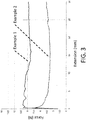
FIG. 3 is a chart reflecting functional forces of Comparative Example 1 and Example 2. - While the invention is amenable to various modifications and alternative forms, specific embodiments have been shown by way of example in the drawings and are described in detail below. The intention, however, is not to limit the invention to the particular embodiments described. On the contrary, the invention is intended to cover all modifications, equivalents, and alternatives falling within the scope of the invention as defined by the appended claims.
- Various embodiments described herein address reducing sliding friction between complementary sliding components in syringe assemblies, such as friction reduction between a first, softer component and a second, more rigid component of a syringe assembly. For example, some embodiments relate to reducing friction between a syringe stopper and a barrel, between a syringe tip cap and a barrel, or between a syringe valve body and valve plug, or other complementary syringe components. In some embodiments, the first component (e.g., a stopper) includes an elastomeric material, such as butyl rubber, and the second component (e.g., a syringe barrel) includes a ceramic material, such as borosilicate glass. While various embodiments are described in association with syringe assembly applications, a variety of applications where reduced friction is sought are contemplated.
-
FIG. 1 is a schematic view of asyringe assembly 10, according to some embodiments. As shown, thesyringe assembly 10 includes asyringe barrel 12, astopper 14 that forms a complementary fit with thesyringe barrel 12, aplunger rod 16, a tip cap orneedle shield 18, and, in the case of a pre-filled embodiment, aliquid 20, such as a medicament, for dispensing from thesyringe assembly 10. As shown, thesyringe barrel 12 and thestopper 14 are first and second complementary syringe components that are slidably engaged with one another, thestopper 14 forming a slidable seal within thesyringe barrel 12. Although thesyringe barrel 12 and thestopper 14 are slidably engaged in a linear relationship, it should be understood that other sliding relationships (e.g., rotational sliding between a valve body and a valve plug) are contemplated. - As shown, the
syringe barrel 12 defines a bore orinner surface 30, also described as a sliding surface. Thesyringe barrel 12 is formed of a suitable material, such as suitable ceramic, polymeric, and metal materials. In some embodiments, thesyringe barrel 12 includes a substantially rigid or hard material, such as a glass material. Although any of a variety of glass compositions are contemplated, according to the examples that follow borosilicate glass has been shown to be an effective material in association with friction-reduction methods according to some embodiments. - As indicated in
FIG. 1 , thestopper 14 defines anouter surface 32 for slidably engaging theinner surface 30 of thesyringe barrel 12. In some embodiments, thestopper 14 includes a softer material than thesyringe barrel 12. For example, thestopper 14 is optionally constructed with one or more barrier films applied to an elastomeric core, where the barrier film(s) define theouter surface 32 of thestopper 14. The elastomeric core can be formed of a variety of elastomeric materials, including: Butyl Rubber, Silicon, materials sold under the trade name "VITON", and the like. The barrier film or films optionally include expanded fluoropolymer films and, such as expanded polytetrafluoroethylene films. Barrierfilms based on expanded PTFE help provide for thin and strong barrier layers to leachables and extractables. Some examples of suitable stopper designs utilizing expanded PTFE and elastomeric materials are described inU.S. Appl. No. 12/915,850 - In some embodiment methods of reducing friction between the
stopper 14 and thesyringe barrel 12 of thesyringe assembly 10, thesyringe barrel 12 is filled with WFI water and sealed to prevent leakage. A cap, a second stopper, or other sealing member (not shown) different than thestopper 14 is optionally utilized to seal the WFI water within thesyringe barrel 12. In other embodiments, theassembly 10, including thestopper 14 is filled with WFI water. The WFI water filledsyringe barrel 12 is exposed to a source of heat, such as saturated steam. For example, the WFI water filledsyringe barrel 12 may be placed in an autoclave with the temperature set at 121 °C or above. The saturated steam will heat the WFI water and thesyringe barrel 12. The WFI water is removed and thesyringe barrel 12 is dried. Following drying, thesyringe barrel 12 is ready for use. Syringe assemblies with syringe barrels thus prepared display lower frictional forces between thesyringe barrel 12 and thestopper 14. - In some embodiments, the
syringe barrel 12 is rinsed with an organic solvent after thesyringe barrel 12 and associated WFI water have been heated with steam. For example, a Hexane solvent may be used to rinse thesyringe barrel 12. After the rinsing step, thesyringe barrel 12 is dried. Drying may be conducted at room temperature (RT) or at elevated temperatures (e.g., at about 90 °C or greater, from about 70 °C to about 110 °C, other at other temperature(s) as desired). The following examples are illustrative of methods of preparing asyringe assembly 10 with reduced friction according to some embodiments. While various methods of reducing friction between thesyringe barrel 12 and thestopper 14 have been described, it should be understood that in other implementations similar methodology is applied to reduce friction between alternative or additional components of thesyringe assembly 10, such as between thesyringe barrel 12 and thetip cap 18, for example. - A syringe stopper was constructed in the following manner: A layer of FEP about 0.5 mils in thickness (FEP 100, DuPont) was laminated to a layer of densified expanded PTFE film [thickness: 1 mil; tensile strength: 13.85ksi (longitudinal), 13.9ksi (transverse); modulus: 19.8ksi (longitudinal), 20.7ksi (transverse); strain to break: 425% (longitudinal), 425% (transverse)]. The two layers were stacked on top of each other in a pin frame and heating to 380 °C in an oven for 15 minutes. A layer of porous expanded PTFE [thickness: 27.5 micrometers, matrix tensile strength: 66.8MPa (longitudinal), 75.8MPa (transverse), strain to break: 131 % (longitudinal), 91 % (transverse), bubble point: 22.6 psi] was placed on the densified ePTFE-FEP laminate such that the porous expanded PTFE layer faced the FEP layer in the laminate. These three layers were placed between two smooth metal plates, the plates were clamped to a clamping pressure of about 1 psi. The plates were then placed in an oven at 305 °C for 15 minutes. The resulting three layer composite material (densified ePTFE - FEP - porous ePTFE) was then cooled to about 40 °C.
- This composite material was then thermoformed using heat and vacuum to create a pre-form. The pre-form was constructed by heating the composite to a sufficiently high temperature and then drawing the composite over a male plug using differential pressure. The composite material was loaded into the thermoforming apparatus such that the densified ePTFE layer faced the plug. The composite was heated using a hot air gun (Steinel HG2310) with air exit temperature of 380°C by placing the gun about 5mm away from the surface of the composite. After 5 seconds, the film was subjected to a vacuum of -85kPa. The composite was continued to be heated for another 15 seconds and cooled to about 40 °C under vacuum.
- The resulting pre-form sample was then inverted and then placed into a rubber molding cavity charged with 3.5 grams of elastomer (50 Durometer halobutyl rubber), and the stopper was formed by compression molding. The mold was built to geometry specific for 1 mL "long" plunger per the ISO standard IS011040-5:2001 (E), with an additional 2% shrinkage factor incorporated.
- The cavity was loaded in a press with both platens preheated to 120 °C. The platens were closed to 55,500 lbs (about 8700 psi total internal pressure). The platens were then heated at 180 °C for 5 minutes and then cooled under pressure to 40 °C. The pressure was released and the stopper was ejected. The resulting stopper was washed using a detergent and triple rinsed with de-ionized water. Stopper samples were then cut from the release sheet using a razor blade. They were subjected to two 30 minutes cycles in an autoclave at 121 °C.
- As constructed, the stoppers were used as in the following examples, which reflect the improved sliding friction of the present invention when compared to that of the comparative example. A new stopper was used in each of the examples.
FIG. 2 provides flow charts illustrating the methods of Examples 2 to 5. - A borosilicate glass syringe (1mL Long Schott forma 3s with a staked needle) was obtained. The syringe was obtained without silicone oil applied. A stopper constructed as described above was inserted into the barrel of the syringe and the Dynamic force was measured. Results are reported in Table I.
- A syringe according to the inventive method was constructed in the following manner: A glass syringe free of silicone oil identical to that used in Example 1 was filled with WFI grade water and placed in an autoclave (121°C for 1 hr), the glass syringe was then dried at 90°Cfor 60 minutes and allowed to cool overnight. The stopper was then inserted into the syringe and the dynamic force was measured to be 4.7N. Results are reported in Table I.
- A glass syringe free of silicone oil identical to that of Example 1 was filled with WFI grade water and placed in an autoclave (121 °C for 1 hr), the glass syringe was then removed from the autoclave, rinsed with hexane and dried at room temperature overnight in a laboratory hood. Another stopper was then inserted into this syringe and the dynamic force was measured to be 1.1 N. Results are reported in Table I.
- A glass syringe free of silicone oil identical to that of Comparative Example 1 was filled with WFI grade water and placed in an autoclave (121 °C for 1 hr), the glass syringe was then removed from the autoclave and dried at room temperature overnight in a laboratory hood. The stopper was then inserted into this syringe and the dynamic force was measured to be 5.9N. Results are reported in Table I.
- A glass syringe free of silicone oil identical to that of Comparative Example 1 was filled with WFI grade water and placed in an autoclave (121 °C for 1 hr), the glass syringe was then removed from the autoclave and then dried at 90 °C for 60 minutes. The syringe was then rinsed with hexane and allowed to dry overnight in a laboratory hood. The stopper was then inserted into this syringe and the dynamic force was measured to be 4.4 N. Results are reported in Table I.
- The syringe of Example 2 was tested per the dye ingress test in USP <381 > to evaluate the seal between the inside of the syringe barrel and the stopper from Example 1. No significant dye ingress was observed.
Table 1 Static Force (N) Dynamic Force (N) Comparative Example 1 10.1 8.5 Example 2 7.0 4.7 Example 3 7.3 1.1 Example 4 8.5 5.9 Example 5 6.4 4.4 - As shown in Table 1, subjecting the glass syringe to the treatments described in Examples 2 through 5 lower the dynamic and static force of the stopper.
- The test was performed as specified by I.S. EN ISO 7886-1 :1998 Annex G, with the following exceptions: i) Syringe is mounted so that nozzle is pointing down, ii) No liquid was expelled; only air was expelled, and iii) Forces resulting from travel from the total graduated capacity position to 20mm from that point were recorded. Static force is defined as the value at the first inflection point in the force versus displacement graph. Dynamic force is the value after the inflection point during travel.
- Materials were evaluated for tensile strength, modulus and strain to break according to ATM D882-10 using 0.25 inch by 3 inch samples and a cross head rate of 20 inches/min and one inch gauge length.
- Various modifications and additions can be made to the exemplary embodiments discussed without departing from the scope of the present invention. For example, while the embodiments described above refer to particular features, the scope of this invention also includes embodiments having different combinations of features and embodiments that do not include all of the described features. Accordingly, the scope of the present invention is intended to embrace all such alternatives, modifications, and variations as fall within the scope of the claims, together with all equivalents thereof.
- Further examples are defined in the following clauses:
- 1. A method of reducing friction on glass comprising the steps of: a. providing a glass surface, b. contacting the glass surface with WFI water, c. applying saturated steam at a temperature of at least 121 °C to heat the glass surface and the WFI water, and d. drying the glass surface.
- 2. The method of clause 1 in which the drying step is performed at above 90 °C.
- 3. The method of clause 1 in which the drying step is performed at room temperature.
- 4. The method of
clause 3 further comprising the steps of: rinsing the glass surface with a solvent following the drying step; and drying the glass surface at or above 90 °C following the rinsing step. - 5. The method of clause 1 in which the glass surface comprises borosilicate glass.
- 6. The method of clause 1 further comprising the step of rinsing the glass surface with an organic solvent.
- 7. The method of
clause 6 in which the rinsing step is performed prior to the drying step. - 8. The method of
clause 6 in which the organic solvent is hexane. - 9. The method of clause 1 in which the glass surface that is provided is substantially free of lubricant prior to contacting the glass surface with WFI water.
- 10. The method of clause 1 in which the glass surface that is provided is substantially free of silicone oil prior to contacting the glass surface with WFI water.
- 11. A method of making a syringe assembly comprising: providing a first syringe component defining a first sliding surface that is substantially free of lubricant; contacting the first sliding surface with water; heating the first sliding surface and the water in contact with the first sliding surface at a temperature of at least 121 °C; and drying the first sliding surface.
- 12. The method of clause 11 in which the water is WFI water.
- 13. The method of clause 11 in which heating the first sliding surface and the water includes applying saturated steam at a temperature of at least 121 °C to heat the first sliding surface and the water.
- 14. The method of clause 11 in which the first component is a syringe stopper.
- 15. The method of clause 11 in which the first sliding surface comprises a glass material.
- 16. The method of clause 11 further comprising: providing a second syringe component defining a second sliding surface configured for sliding engagement with the first sliding surface; and slidably contacting the first sliding surface with the second sliding surface.
- 17. The method of
clause 16 in which the second syringe component is softer than the first syringe component. - 18. The method of
clause 16, wherein the first sliding surface is slidably contacted with the second sliding surface after applying saturated steam to heat the first sliding surface and the water in contact with the first sliding surface. - 19. The method of
clause 16 in which the first component is a syringe barrel, the second component is a syringe stopper, and the method further comprises pre-filling the syringe barrel with a medicament and storing the syringe assembly. - 20. The method of clause 11, further comprising at least one of: drying the first sliding surface at room temperature after applying saturated steam, drying the first sliding surface at or above 90 °C after applying saturated steam, and rinsing the first sliding surface with an organic solvent after applying the saturated steam.
- 21. A syringe assembly manufactured by the method of clause 11.
- 22. A component of a syringe assembly that is prepared for sliding engagement with a second, complementary component of the syringe assembly by a process comprising: contacting the first sliding surface with WFI water; applying saturated steam to heat the first sliding surface and the WFI water in contact with the first sliding surface; and drying the first sliding surface.
- 23. The component of clause 22, wherein the component is a syringe barrel and the first sliding surface is an interior surface of the syringe barrel.
- 24. The component of clause 22, wherein the first sliding surface is substantially free of silicone oil.
Claims (10)
- A component of a syringe assembly that is prepared for sliding engagement with a second, complementary component of the syringe assembly by a process comprising:contacting the first sliding surface with water for injection (WFI) water;applying saturated steam to heat the first sliding surface and the WFI water in contact with the first sliding surface; anddrying the first sliding surface.
- The component of claim 1, wherein the component is a syringe barrel and the first sliding surface is an interior surface of the syringe barrel.
- The component of claim 1, wherein the first sliding surface is substantially free of silicone oil.
- The component of claims 1 to 3, wherein the first sliding surface is heated at a temperature of at least 121 °C.
- The component of claims 1 to 4, wherein the component comprises a glass material.
- The component of claim 5, wherein the component comprises borosilicate glass.
- The component of claims 1 to 6, wherein the second, complementary component is softer than the component.
- The component of claims 1 to 7, wherein the drying step is performed at above 90 °C.
- The component of claims 1 to 7, wherein the drying step is performed at room temperature.
- The component of claims 1 to 9, wherein the process further comprises the steps of rinsing the first sliding surface with a solvent following the drying step; and drying the first sliding surface at or above 90 °C following the rinsing step.
Applications Claiming Priority (3)
| Application Number | Priority Date | Filing Date | Title |
|---|---|---|---|
| US201161475851P | 2011-04-15 | 2011-04-15 | |
| PCT/US2012/033616 WO2012142479A1 (en) | 2011-04-15 | 2012-04-13 | Method of reducing friction between syringe components |
| EP12717991.9A EP2696919B1 (en) | 2011-04-15 | 2012-04-13 | Method of reducing friction between syringe components |
Related Parent Applications (2)
| Application Number | Title | Priority Date | Filing Date |
|---|---|---|---|
| EP12717991.9A Division EP2696919B1 (en) | 2011-04-15 | 2012-04-13 | Method of reducing friction between syringe components |
| EP12717991.9A Division-Into EP2696919B1 (en) | 2011-04-15 | 2012-04-13 | Method of reducing friction between syringe components |
Publications (1)
| Publication Number | Publication Date |
|---|---|
| EP3560535A1 true EP3560535A1 (en) | 2019-10-30 |
Family
ID=46022695
Family Applications (2)
| Application Number | Title | Priority Date | Filing Date |
|---|---|---|---|
| EP19179922.0A Withdrawn EP3560535A1 (en) | 2011-04-15 | 2012-04-13 | Method of reducing friction between syringe components |
| EP12717991.9A Active EP2696919B1 (en) | 2011-04-15 | 2012-04-13 | Method of reducing friction between syringe components |
Family Applications After (1)
| Application Number | Title | Priority Date | Filing Date |
|---|---|---|---|
| EP12717991.9A Active EP2696919B1 (en) | 2011-04-15 | 2012-04-13 | Method of reducing friction between syringe components |
Country Status (4)
| Country | Link |
|---|---|
| US (3) | US9539394B2 (en) |
| EP (2) | EP3560535A1 (en) |
| CA (1) | CA2832976C (en) |
| WO (1) | WO2012142479A1 (en) |
Families Citing this family (11)
| Publication number | Priority date | Publication date | Assignee | Title |
|---|---|---|---|---|
| US10471212B2 (en) | 2009-10-29 | 2019-11-12 | W. L. Gore & Associates, Inc. | Silicone free drug delivery devices |
| US9597458B2 (en) | 2009-10-29 | 2017-03-21 | W. L. Gore & Associates, Inc. | Fluoropolymer barrier materials for containers |
| JP2013509270A (en) * | 2009-10-29 | 2013-03-14 | ゴア エンタープライズ ホールディングス,インコーポレイティド | Syringe stopper covered with expanded PTFE |
| US11612697B2 (en) | 2010-10-29 | 2023-03-28 | W. L. Gore & Associates, Inc. | Non-fluoropolymer tie layer and fluoropolymer barrier layer |
| US20140142500A1 (en) * | 2012-04-23 | 2014-05-22 | Zogenix, Inc. | Piston closures for drug delivery capsules |
| FR3041334B1 (en) * | 2015-09-21 | 2020-02-14 | Disposable-Lab | PROCESS FOR SEALING A CONTAINER COMPRISING AT LEAST ONE PLUG, IN PARTICULAR A CARPULE, MEANS OF INSERTION AND ASSOCIATED SEALING LINE |
| US10471211B2 (en) | 2016-01-15 | 2019-11-12 | W. L. Gore & Associates, Inc. | Medical delivery device with laminated stopper |
| US10869967B2 (en) * | 2017-01-06 | 2020-12-22 | Verily Life Sciences Llc | Rigid sensor stopper for use in drug delivery devices |
| US20250229036A1 (en) * | 2022-04-04 | 2025-07-17 | Becton, Dickinson And Company | Multi-Chamber Syringe with Pressure Valve for Sequential Delivery of Fluids and Methods of Use |
| US20260077130A1 (en) | 2024-09-18 | 2026-03-19 | Regeneron Pharmaceuticals, Inc. | Systems and methods for precision dose delivery, sterlization, and packaging of medical devices |
| EP4736911A1 (en) * | 2024-10-29 | 2026-05-06 | Becton Dickinson France | Method for manufacturing a prefilled syringe to reduce gliding force therein |
Citations (4)
| Publication number | Priority date | Publication date | Assignee | Title |
|---|---|---|---|---|
| GB399336A (en) * | 1932-11-21 | 1933-10-05 | Josef Schoene | Device for the sterilization of injection-syringes by means of boiling water and steam |
| US5207983A (en) * | 1992-01-29 | 1993-05-04 | Sterling Winthrop Inc. | Method of terminal steam sterilization |
| WO2001060534A1 (en) * | 2000-02-18 | 2001-08-23 | Eco2 Sa | Device and method for the precision cleaning of objects |
| WO2011027872A1 (en) * | 2009-09-04 | 2011-03-10 | 国立大学法人東京大学 | Inorganic structure, method for producing same, and method for producing inorganic thin film |
Family Cites Families (25)
| Publication number | Priority date | Publication date | Assignee | Title |
|---|---|---|---|---|
| AU623598B2 (en) | 1987-06-19 | 1992-05-21 | Terumo Kabushiki Kaisha | Medical instrument and production thereof |
| JPH0534669Y2 (en) | 1988-03-16 | 1993-09-02 | ||
| US5112664A (en) | 1990-11-30 | 1992-05-12 | W. L. Gore & Associates, Inc. | Shielded gasket assembly |
| US5279606A (en) | 1991-08-28 | 1994-01-18 | Habley Medical Technology Corporation | Non-reactive composite sealing barrier |
| AU4408693A (en) | 1992-12-10 | 1994-07-04 | W.L. Gore & Associates, Inc. | Composite article |
| DE69428914T2 (en) | 1994-10-31 | 2002-04-04 | W.L. Gore & Associates, Inc. | STIFF LEAF-SHAPED POLYTETRAFLUORETHYLENE MATERIAL |
| JP3387775B2 (en) | 1997-05-22 | 2003-03-17 | 株式会社大協精工 | Sealing stopper for syringe and prefilled syringe |
| AU9783498A (en) | 1997-10-03 | 1999-04-27 | Gore Enterprise Holdings, Inc. | An expanded ptfe covered space-filling implant |
| US20110282185A1 (en) * | 1998-06-29 | 2011-11-17 | Bracco Suisse S.A. | Gasket for Pre-Filled Syringe and Pre-Filled Syringe |
| DE19831112C2 (en) * | 1998-07-11 | 2003-06-26 | Schott Glas | Universal glass container for medical purposes |
| KR100313828B1 (en) * | 1999-04-27 | 2001-11-15 | 윤여생 | Method for removing glass particle adhered to the inner wall of glass cartridge |
| US6331351B1 (en) | 1999-09-22 | 2001-12-18 | Gore Enterprise Holdings, Inc. | Chemically active filter material |
| JP2002086481A (en) | 2000-09-14 | 2002-03-26 | Terumo Corp | Method for manufacturing gasket |
| DE10108958A1 (en) * | 2001-02-19 | 2002-09-12 | Arzneimittelgesellschaft Mit B | Device and method for manufacturing a syringe for medical purposes |
| US20020164265A1 (en) * | 2001-05-04 | 2002-11-07 | Hetzler Kevin G. | Method of removing refractive defects in cyclic olefin medical devices |
| US6541589B1 (en) | 2001-10-15 | 2003-04-01 | Gore Enterprise Holdings, Inc. | Tetrafluoroethylene copolymer |
| US20030211264A1 (en) | 2002-05-09 | 2003-11-13 | Farnsworth Ted Ray | Expanded polytetrafluoroethylene (ePTFE)-reinforced perfluoroelastomers (FFKM) |
| US20050238872A1 (en) | 2004-04-23 | 2005-10-27 | Kennedy Michael E | Fluoropolymer barrier material |
| FR2890316B1 (en) * | 2005-09-02 | 2007-10-05 | Aguettant Soc Par Actions Simp | SYRINGE FOR FILLING THEN STERILIZED BY STEAM AUTOCLAVING. |
| US8637144B2 (en) | 2007-10-04 | 2014-01-28 | W. L. Gore & Associates, Inc. | Expandable TFE copolymers, method of making, and porous, expended articles thereof |
| TR201815698T4 (en) | 2007-12-26 | 2018-11-21 | Daikyo Seiko Ltd | Rubber molds. |
| CN101909675B (en) * | 2007-12-28 | 2013-03-13 | 泰尔茂株式会社 | Gasket for syringe and syringe comprising the gasket |
| JP2013509270A (en) | 2009-10-29 | 2013-03-14 | ゴア エンタープライズ ホールディングス,インコーポレイティド | Syringe stopper covered with expanded PTFE |
| US9597458B2 (en) | 2009-10-29 | 2017-03-21 | W. L. Gore & Associates, Inc. | Fluoropolymer barrier materials for containers |
| US9878101B2 (en) * | 2010-11-12 | 2018-01-30 | Sio2 Medical Products, Inc. | Cyclic olefin polymer vessels and vessel coating methods |
-
2012
- 2012-04-13 WO PCT/US2012/033616 patent/WO2012142479A1/en not_active Ceased
- 2012-04-13 EP EP19179922.0A patent/EP3560535A1/en not_active Withdrawn
- 2012-04-13 CA CA2832976A patent/CA2832976C/en active Active
- 2012-04-13 US US13/446,900 patent/US9539394B2/en active Active
- 2012-04-13 EP EP12717991.9A patent/EP2696919B1/en active Active
-
2016
- 2016-10-26 US US15/335,112 patent/US20170043096A1/en not_active Abandoned
-
2020
- 2020-11-02 US US17/087,195 patent/US20210046245A1/en not_active Abandoned
Patent Citations (4)
| Publication number | Priority date | Publication date | Assignee | Title |
|---|---|---|---|---|
| GB399336A (en) * | 1932-11-21 | 1933-10-05 | Josef Schoene | Device for the sterilization of injection-syringes by means of boiling water and steam |
| US5207983A (en) * | 1992-01-29 | 1993-05-04 | Sterling Winthrop Inc. | Method of terminal steam sterilization |
| WO2001060534A1 (en) * | 2000-02-18 | 2001-08-23 | Eco2 Sa | Device and method for the precision cleaning of objects |
| WO2011027872A1 (en) * | 2009-09-04 | 2011-03-10 | 国立大学法人東京大学 | Inorganic structure, method for producing same, and method for producing inorganic thin film |
Also Published As
| Publication number | Publication date |
|---|---|
| CA2832976C (en) | 2018-12-18 |
| US20210046245A1 (en) | 2021-02-18 |
| US9539394B2 (en) | 2017-01-10 |
| EP2696919A1 (en) | 2014-02-19 |
| CA2832976A1 (en) | 2012-10-18 |
| US20170043096A1 (en) | 2017-02-16 |
| EP2696919B1 (en) | 2019-07-24 |
| US20120260607A1 (en) | 2012-10-18 |
| WO2012142479A1 (en) | 2012-10-18 |
Similar Documents
| Publication | Publication Date | Title |
|---|---|---|
| US20210046245A1 (en) | Method Of Reducing Friction Between Syringe Components | |
| US11654241B2 (en) | Fluoropolymer barrier material for containers | |
| EP3308816B1 (en) | Syringe stopper coated with densified expanded ptfe | |
| AU2020201401B2 (en) | Three-position plungers, film coated plungers and related syringe assemblies | |
| HK40015713A (en) | Method of reducing friction between syringe components | |
| HK40036879A (en) | Syringe cap coated with expanded ptfe | |
| HK40011574A (en) | Syringe stopper coated with expanded ptfe | |
| AU2017202553B2 (en) | Fluoropolymer barrier materials for containers | |
| HK1240866A1 (en) | Syringe stopper coated with expanded ptfe | |
| HK1239601A1 (en) | Syringe stopper coated with expanded ptfe | |
| HK1248628B (en) | Syringe stopper coated with densified expanded ptfe | |
| HK1240866B (en) | Syringe stopper coated with expanded ptfe |
Legal Events
| Date | Code | Title | Description |
|---|---|---|---|
| PUAI | Public reference made under article 153(3) epc to a published international application that has entered the european phase |
Free format text: ORIGINAL CODE: 0009012 |
|
| STAA | Information on the status of an ep patent application or granted ep patent |
Free format text: STATUS: REQUEST FOR EXAMINATION WAS MADE |
|
| 17P | Request for examination filed |
Effective date: 20190613 |
|
| AC | Divisional application: reference to earlier application |
Ref document number: 2696919 Country of ref document: EP Kind code of ref document: P |
|
| AK | Designated contracting states |
Kind code of ref document: A1 Designated state(s): AL AT BE BG CH CY CZ DE DK EE ES FI FR GB GR HR HU IE IS IT LI LT LU LV MC MK MT NL NO PL PT RO RS SE SI SK SM TR |
|
| REG | Reference to a national code |
Ref country code: HK Ref legal event code: DE Ref document number: 40015713 Country of ref document: HK |
|
| STAA | Information on the status of an ep patent application or granted ep patent |
Free format text: STATUS: EXAMINATION IS IN PROGRESS |
|
| 17Q | First examination report despatched |
Effective date: 20221108 |
|
| RAP3 | Party data changed (applicant data changed or rights of an application transferred) |
Owner name: W.L. GORE & ASSOCIATES, INC. |
|
| STAA | Information on the status of an ep patent application or granted ep patent |
Free format text: STATUS: THE APPLICATION IS DEEMED TO BE WITHDRAWN |
|
| 18D | Application deemed to be withdrawn |
Effective date: 20251101 |