EP3560072B1 - Motoreducteur compact - Google Patents
Motoreducteur compact Download PDFInfo
- Publication number
- EP3560072B1 EP3560072B1 EP17828737.1A EP17828737A EP3560072B1 EP 3560072 B1 EP3560072 B1 EP 3560072B1 EP 17828737 A EP17828737 A EP 17828737A EP 3560072 B1 EP3560072 B1 EP 3560072B1
- Authority
- EP
- European Patent Office
- Prior art keywords
- shell
- actuator according
- stator
- extensions
- axis
- Prior art date
- Legal status (The legal status is an assumption and is not a legal conclusion. Google has not performed a legal analysis and makes no representation as to the accuracy of the status listed.)
- Active
Links
Images



Classifications
-
- H—ELECTRICITY
- H02—GENERATION; CONVERSION OR DISTRIBUTION OF ELECTRIC POWER
- H02K—DYNAMO-ELECTRIC MACHINES
- H02K7/00—Arrangements for handling mechanical energy structurally associated with dynamo-electric machines, e.g. structural association with mechanical driving motors or auxiliary dynamo-electric machines
- H02K7/10—Structural association with clutches, brakes, gears, pulleys or mechanical starters
- H02K7/116—Structural association with clutches, brakes, gears, pulleys or mechanical starters with gears
-
- H—ELECTRICITY
- H02—GENERATION; CONVERSION OR DISTRIBUTION OF ELECTRIC POWER
- H02K—DYNAMO-ELECTRIC MACHINES
- H02K1/00—Details of the magnetic circuit
- H02K1/06—Details of the magnetic circuit characterised by the shape, form or construction
- H02K1/12—Stationary parts of the magnetic circuit
- H02K1/14—Stator cores with salient poles
- H02K1/146—Stator cores with salient poles consisting of a generally annular yoke with salient poles
-
- F—MECHANICAL ENGINEERING; LIGHTING; HEATING; WEAPONS; BLASTING
- F16—ENGINEERING ELEMENTS AND UNITS; GENERAL MEASURES FOR PRODUCING AND MAINTAINING EFFECTIVE FUNCTIONING OF MACHINES OR INSTALLATIONS; THERMAL INSULATION IN GENERAL
- F16H—GEARING
- F16H1/00—Toothed gearings for conveying rotary motion
- F16H1/02—Toothed gearings for conveying rotary motion without gears having orbital motion
- F16H1/20—Toothed gearings for conveying rotary motion without gears having orbital motion involving more than two intermeshing members
- F16H1/22—Toothed gearings for conveying rotary motion without gears having orbital motion involving more than two intermeshing members with a plurality of driving or driven shafts; with arrangements for dividing torque between two or more intermediate shafts
- F16H1/227—Toothed gearings for conveying rotary motion without gears having orbital motion involving more than two intermeshing members with a plurality of driving or driven shafts; with arrangements for dividing torque between two or more intermediate shafts comprising two or more gearwheels in mesh with the same internally toothed wheel
-
- H—ELECTRICITY
- H02—GENERATION; CONVERSION OR DISTRIBUTION OF ELECTRIC POWER
- H02K—DYNAMO-ELECTRIC MACHINES
- H02K1/00—Details of the magnetic circuit
- H02K1/06—Details of the magnetic circuit characterised by the shape, form or construction
- H02K1/12—Stationary parts of the magnetic circuit
- H02K1/14—Stator cores with salient poles
- H02K1/146—Stator cores with salient poles consisting of a generally annular yoke with salient poles
- H02K1/148—Sectional cores
-
- H—ELECTRICITY
- H02—GENERATION; CONVERSION OR DISTRIBUTION OF ELECTRIC POWER
- H02K—DYNAMO-ELECTRIC MACHINES
- H02K11/00—Structural association of dynamo-electric machines with electric components or with devices for shielding, monitoring or protection
- H02K11/02—Structural association of dynamo-electric machines with electric components or with devices for shielding, monitoring or protection for suppression of electromagnetic interference
-
- H—ELECTRICITY
- H02—GENERATION; CONVERSION OR DISTRIBUTION OF ELECTRIC POWER
- H02K—DYNAMO-ELECTRIC MACHINES
- H02K11/00—Structural association of dynamo-electric machines with electric components or with devices for shielding, monitoring or protection
- H02K11/30—Structural association with control circuits or drive circuits
-
- H—ELECTRICITY
- H02—GENERATION; CONVERSION OR DISTRIBUTION OF ELECTRIC POWER
- H02K—DYNAMO-ELECTRIC MACHINES
- H02K11/00—Structural association of dynamo-electric machines with electric components or with devices for shielding, monitoring or protection
- H02K11/30—Structural association with control circuits or drive circuits
- H02K11/33—Drive circuits, e.g. power electronics
-
- H—ELECTRICITY
- H02—GENERATION; CONVERSION OR DISTRIBUTION OF ELECTRIC POWER
- H02K—DYNAMO-ELECTRIC MACHINES
- H02K11/00—Structural association of dynamo-electric machines with electric components or with devices for shielding, monitoring or protection
- H02K11/40—Structural association with grounding devices
-
- H—ELECTRICITY
- H02—GENERATION; CONVERSION OR DISTRIBUTION OF ELECTRIC POWER
- H02K—DYNAMO-ELECTRIC MACHINES
- H02K5/00—Casings; Enclosures; Supports
- H02K5/04—Casings or enclosures characterised by the shape, form or construction thereof
-
- H—ELECTRICITY
- H02—GENERATION; CONVERSION OR DISTRIBUTION OF ELECTRIC POWER
- H02K—DYNAMO-ELECTRIC MACHINES
- H02K5/00—Casings; Enclosures; Supports
- H02K5/04—Casings or enclosures characterised by the shape, form or construction thereof
- H02K5/22—Auxiliary parts of casings not covered by groups H02K5/06-H02K5/20, e.g. shaped to form connection boxes or terminal boxes
- H02K5/225—Terminal boxes or connection arrangements
-
- H—ELECTRICITY
- H02—GENERATION; CONVERSION OR DISTRIBUTION OF ELECTRIC POWER
- H02K—DYNAMO-ELECTRIC MACHINES
- H02K7/00—Arrangements for handling mechanical energy structurally associated with dynamo-electric machines, e.g. structural association with mechanical driving motors or auxiliary dynamo-electric machines
- H02K7/10—Structural association with clutches, brakes, gears, pulleys or mechanical starters
- H02K7/116—Structural association with clutches, brakes, gears, pulleys or mechanical starters with gears
- H02K7/1163—Structural association with clutches, brakes, gears, pulleys or mechanical starters with gears where at least two gears have non-parallel axes without having orbital motion
-
- F—MECHANICAL ENGINEERING; LIGHTING; HEATING; WEAPONS; BLASTING
- F16—ENGINEERING ELEMENTS AND UNITS; GENERAL MEASURES FOR PRODUCING AND MAINTAINING EFFECTIVE FUNCTIONING OF MACHINES OR INSTALLATIONS; THERMAL INSULATION IN GENERAL
- F16H—GEARING
- F16H57/00—General details of gearing
- F16H57/02—Gearboxes; Mounting gearing therein
- F16H2057/02034—Gearboxes combined or connected with electric machines
-
- F—MECHANICAL ENGINEERING; LIGHTING; HEATING; WEAPONS; BLASTING
- F16—ENGINEERING ELEMENTS AND UNITS; GENERAL MEASURES FOR PRODUCING AND MAINTAINING EFFECTIVE FUNCTIONING OF MACHINES OR INSTALLATIONS; THERMAL INSULATION IN GENERAL
- F16H—GEARING
- F16H57/00—General details of gearing
- F16H57/02—Gearboxes; Mounting gearing therein
- F16H2057/02039—Gearboxes for particular applications
- F16H2057/02069—Gearboxes for particular applications for industrial applications
-
- F—MECHANICAL ENGINEERING; LIGHTING; HEATING; WEAPONS; BLASTING
- F16—ENGINEERING ELEMENTS AND UNITS; GENERAL MEASURES FOR PRODUCING AND MAINTAINING EFFECTIVE FUNCTIONING OF MACHINES OR INSTALLATIONS; THERMAL INSULATION IN GENERAL
- F16H—GEARING
- F16H57/00—General details of gearing
- F16H57/02—Gearboxes; Mounting gearing therein
- F16H2057/02039—Gearboxes for particular applications
- F16H2057/02082—Gearboxes for particular applications for application in vehicles other than propelling, e.g. adjustment of parts
-
- F—MECHANICAL ENGINEERING; LIGHTING; HEATING; WEAPONS; BLASTING
- F16—ENGINEERING ELEMENTS AND UNITS; GENERAL MEASURES FOR PRODUCING AND MAINTAINING EFFECTIVE FUNCTIONING OF MACHINES OR INSTALLATIONS; THERMAL INSULATION IN GENERAL
- F16H—GEARING
- F16H57/00—General details of gearing
- F16H57/02—Gearboxes; Mounting gearing therein
- F16H2057/02086—Measures for reducing size of gearbox, e.g. for creating a more compact transmission casing
-
- H—ELECTRICITY
- H02—GENERATION; CONVERSION OR DISTRIBUTION OF ELECTRIC POWER
- H02K—DYNAMO-ELECTRIC MACHINES
- H02K1/00—Details of the magnetic circuit
- H02K1/06—Details of the magnetic circuit characterised by the shape, form or construction
- H02K1/12—Stationary parts of the magnetic circuit
- H02K1/14—Stator cores with salient poles
-
- H—ELECTRICITY
- H02—GENERATION; CONVERSION OR DISTRIBUTION OF ELECTRIC POWER
- H02K—DYNAMO-ELECTRIC MACHINES
- H02K2203/00—Specific aspects not provided for in the other groups of this subclass relating to the windings
- H02K2203/03—Machines characterised by the wiring boards, i.e. printed circuit boards or similar structures for connecting the winding terminations
-
- H—ELECTRICITY
- H02—GENERATION; CONVERSION OR DISTRIBUTION OF ELECTRIC POWER
- H02K—DYNAMO-ELECTRIC MACHINES
- H02K2213/00—Specific aspects, not otherwise provided for and not covered by codes H02K2201/00 - H02K2211/00
- H02K2213/03—Machines characterised by numerical values, ranges, mathematical expressions or similar information
-
- H—ELECTRICITY
- H02—GENERATION; CONVERSION OR DISTRIBUTION OF ELECTRIC POWER
- H02K—DYNAMO-ELECTRIC MACHINES
- H02K7/00—Arrangements for handling mechanical energy structurally associated with dynamo-electric machines, e.g. structural association with mechanical driving motors or auxiliary dynamo-electric machines
- H02K7/14—Structural association with mechanical loads, e.g. with hand-held machine tools or fans
Definitions
- the present invention relates to the field of mechatronic actuators intended in particular for controlling mechanical components of a motor vehicle, for example ventilation grilles, air conditioning flaps or more generally valve shutters. These are components requiring a relatively high torque, with a displacement of a few tens of degrees and a typical positioning accuracy of less than 5 degrees, as well as a minimal footprint.
- the patent application US2013 / 104682 describes a mechatronic actuator consisting of a housing incorporating in a shell a three-phase electric motor formed by a stator excited by electric coils and by a magnetized rotor, driving an output shaft by means of a gear train.
- the axis of said rotor, the axis of the output shaft and the axes of the intermediate toothed wheels are parallel.
- the shell has a longitudinal axis
- the box has three fixing extensions arranged at three corners of the box, each of said extensions being crossed by a bore, the axis of which is parallel to the mechanical axes of the engine and of the toothed wheels.
- the vibration and shock resistance is not completely satisfactory for automotive applications, and the vibrations can cause the printed circuit to exit unexpectedly from its supports, or the accidental dismantling of certain mechanical or electromagnetic components.
- the invention relates in its most general sense to a mechatronic actuator consisting of a housing incorporating in a shell a three-phase electric motor formed by a stator excited by electric coils and by a magnetized rotor, driving an output shaft by means of a gear train, the axis of said rotor, the axis of the output shaft and the axes of the toothed wheels intermediates being parallel, the shell having a longitudinal axis (L), the box having three fixing extensions arranged at three corners of the box, each of said extensions being crossed by a bore whose axis is parallel to the mechanical axes of the engine and cogwheels.
- one of said extensions has a positioning lug in a complementary housing, another of said extensions has a clipping claw.
- the invention also relates to a method of fitting a mechatronic actuator referred to above.
- the method consists in positioning said actuator by engaging said tab in the reception area, then tilting it relative to the lower edge of said tab, until the hook is engaged in the complementary part of the reception structure.
- the invention also relates to several verified embodiments, which can be carried out alone or in combination.
- said extensions have a dual function of fixing either by screwing or rivet passing through said bores or by the clipping of said clipping claw during the pivoting of the housing relative to said tab which is wedged in a housing provided on a reception structure.
- the extension provided on the same side face as the extension provided with the tab, has a hook which cooperates with a complementary part of said reception structure.
- one of the transverse faces is extended by a hollow sleeve for the introduction of a male connector provided on a connection cord.
- the cover of said shell has an opening inside which is placed a guide bearing for the output wheel.
- said shell is drilled symmetrically to allow the passage of a through transmission shaft or the connection to the actuator of two transmission shafts.
- the output wheel can have different sections, on one side and the other, for connecting axes of different sections.
- said stator has the shape of a radial triangular star, the three coiled poles of which form the three star branches, the axes of symmetry of two consecutive coiled poles forming a mechanical angle of 120 °.
- the box also incorporates an electronic circuit comprising a capacitor for filtering the electrical signal, the shell having a longitudinal axis (L).
- the stator is positioned in the housing so that the axis of symmetry of one of said three wound poles forms with the longitudinal axis (L) an angle of 90 °.
- the stator is positioned in the housing so that the axis of symmetry of that of the three coiled poles forming with the longitudinal axis (L) an angle of between 70 and 110 ° has a chamfer at the level of the area closest to the side wall.
- said filtering capacitor consists of a tubular component mounted perpendicular to the plane of the printed circuit, said capacitor being positioned in the space delimited on the one hand by two consecutive stator poles (42, 43) whose pole positioned between 70 and 110 ° relative to the median plane, and on the other hand by the angle of the housing located opposite said two complementary stator poles.
- all of the electronic components are soldered onto the surface of the printed circuit oriented towards the stator, said printed circuit having a hole through which the axis of the rotor passes and tinned holes for the insertion of the connection pads of the three coils.
- the printed circuit has at least one hole or a notch for the passage of a mechanical axis of one of said toothed wheels.
- the printed circuit has a dimension such that its projection in a transverse plane fits into the projection of the circle circumscribed to said stator, on said transverse plane, except for the rear part of the printed circuit corresponding to the connection of the electrical connector and in that said printed circuit is positioned with respect to said casing to preserve, with respect to the side faces on either side, a space of a width greater than 10% of the internal width of said casing.
- the actuator according to the illustrative example comprises, according to a particular embodiment, a metal spring positioned in compression between an uninsulated area of the yoke of said stator and a conductive ground track of the printed circuit.
- said stator has an uninsulated bore to receive the lower part of said spring, the peripheral surface of said spring coming into contact with the uninsulated interior surface of said bore when the spring is put into compression by the printed circuit.
- said housing is constituted by a shell and a complementary closing cover, one of the lateral faces of said shell having an internal protuberance pierced by an emerging cavity, positioned between two toothed wheels, and a second protuberance pierced by a cavity of non-circular section, said cover having two studs complementary to said cavities, of a length greater than other connecting studs, the cover also having guide bearings of the upper end of the mechanical axes.
- said cover also has at least one stud forming a stopper for the printed circuit, said stopper not coming into contact with the printed circuit when the latter is in the nominal position.
- said cover also has at least one stud forming a stopper for the stator, said stopper not coming into contact with the stator when the latter is in the nominal position.
- the housing has three fixing extensions arranged at three corners of the housing, each of said extensions being crossed by a bore whose axis is parallel to the axes. mechanics of the motor and of the toothed wheels, one of said extension having a positioning lug in a complementary housing, another of said extensions having a clipping claw during the pivoting of the housing relative to said positioning lug.
- the figure 1 shows an external view of an example of an actuator, consisting of a shell (1) closed by a cover (2).
- the shell (1) has three extensions (3, 4, 5) at three of its angles. Each of the extensions has a hole respectively (6, 7, 8).
- one of the extensions (5) has a tab (9) which can be wedged in a housing provided on a reception structure.
- the extension (4) provided on the same side face (10) as the extension (5) provided with the tab (9), has a hook (11) which cooperates with a complementary part of the reception structure.
- the installation is done by positioning the actuator by engaging the tab (9) in the reception area, then tilting it with respect to the lower edge (12) of the tab, until the hook (11) or engaged in the complementary part of the reception structure.
- One of the transverse faces (13) is extended by a hollow sleeve (14) for the introduction of a male connector provided on a connection cord.
- the cover (2) has an opening (15) inside which is placed a bearing (16) for guiding the output wheel.
- the housing can also be drilled symmetrically to allow the passage of a through transmission shaft or the connection to the actuator of two transmission shafts.
- the output wheel can have different sections, on one side and the other, for the connection of axes of different sections.
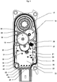
- the figure 2 shows a top view of the actuator after removal of the cover (2).
- the output wheel (17) is driven by a gear train formed by a succession of toothed wheels (17 to 21), mounted on parallel axes, perpendicular to the connecting plane between the cover (2) and the shell ( 1).
- the rotor (71) of the electric motor drives a wheel (21) driving the gear train.
- the rotor axis passes through a hole in a printed circuit (22).
- No electronic component is mounted on the upper face of the printed circuit (22) which allows realization by a wave soldering process in a single simple machine pass.
- the printed circuit (22) has a series of tinned holes (23 to 26) for the connection with the pins of the connector, extending perpendicular to the median plane.
- tinned holes 27 to 31
- a sixth tinned hole being masked on the figure 2 by the toothed wheel (20) - for the connection of the power supply pads of the electric coils.
- These pads are for example press-fit pads ("press-fitt" in English) making it possible to make the electrical connection of the printed circuit (22) without soldering, by simply driving the printed circuit (22) on the erect pads according to a direction perpendicular to the surface of the printed circuit (22).
- the surface of the printed circuit (22) does not cover the enveloping surface of the stator (32).
- the projection of the circle circumscribed to the stator (32) on a transverse plane entirely covers the projected surface of the printed circuit (22) on this same plane, with the exception of the part (33) of the printed circuit (22) ensuring the connection with the connector.
- the printed circuit (22) does not come into contact with the edges of the shell (1), but preserves on either side a space (34, 35) with a width greater than 10% of the width. interior of the hull (1).
- the inner surface of the side wall (38) of the shell (1) has a first inner protrusion (36) and a second inner protrusion (37).
- the first inner protrusion (36) is positioned in the space available between the output wheel (17) and the intermediate toothed wheel (19). It presents a cavity (39) of hexagonal section to receive a positioning pin of circular section (60) provided on the cover (2) and visible in figure 5 .
- the second inner protrusion (37) is positioned in the corner of the shell (1) devoid of outer protuberance. It has an oblong opening cavity (40) in the example described, with a main axis parallel to the lateral face (38) to facilitate the positioning of the cover (2) relative to the shell (1).
- This emerging cavity (40) is intended to receive an anti-rotation pin (61), visible in figure 5 having a cross-shaped section and extending perpendicular to the inner surface of the cover (2).
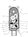
- the figure 3 shows a view of the inside of the actuator after removal of the cover (2) and of the printed circuit (22).
- the stator (32) has three coiled poles (41 to 43) extending radially and is formed by a stacked sheet structure. Each pole (41 to 43) has a central tooth surrounded by a coil.
- the median axes (44 to 46) of the respectively wound poles (41 to 43) form a mechanical angle of 120 ° two by two.
- the stator thus has the shape of a radial triangular star with each coiled pole forming a star branch.
- the shell (1) has a longitudinal axis (L) connecting the connector (14) to the output wheel (17). This longitudinal axis is parallel to the two side faces of the shell (1), each extending along the longitudinal direction.
- the stator (32) is positioned in the shell (1) such that one of the poles (43) is oriented to form an angle of approximately 90 ° with respect to the longitudinal axis (L) of the shell ( 1). This positioning makes it possible to reduce the width of the shell and therefore the general size of the actuator and to optimize the occupation of the interior space of the shell (1).
- a tolerance of ⁇ 20 °, and preferably ⁇ 10 ° is possible because the effect on the bulk remains minimal due to an impact according to the cosine of this angular variation.
- the effect of a slight angular offset from the optimum 90 ° position can be further reduced by providing a chamfer (48) at the angle of the stator contacting the side face (47).
- This positioning of the rotor (32) also makes it possible to free up a space (49) between the two poles (42, 43) of the stator, and the angle (50) of the shell.
- This space makes it possible to position a filter capacitor (51), typically chemical and cylindrical in shape, soldered to the printed circuit (22).
- the figure 4 shows a partial enlarged view of the stator (32) and the printed circuit (22).
- the actuator comprises a metal spring (52) introduced into a through hole (53) formed in the stator yoke.
- the bottom of the shell (1) has a stepped or inclined surface facing this bore (53), to form a zone for receiving the lower end (54) of the spring which is not parallel to the transverse plane. This configuration leads to buckling of the spring, when it is put under stress, which forces a mechanical and therefore electrical contact between the turns of the spring (52) and the inner surface of the bore (53).
- the spring (52) comes into contact with a conductive track of the printed circuit (22), which is connected to ground.
- the figure 5 shows a view of the inner surface of the cover (2).
- the cover (2) also has two assembly pins (60, 61) whose length is greater than the bearings (62 to 65) so as to allow the precise positioning of the cover (2) relative to the shell (1) and mechanical elements, in particular the axes of the intermediate toothed wheels, of the output wheel and of the rotor (71), so that, when the cover (2) is brought closer to the shell (1), the ends axes engage without difficulty in the corresponding bearings.
- the cover also has four stops (66 to 69) intended to limit unexpected movements of the printed circuit (22) resulting from vibration. These stops (66 to 69) do not come into contact with the surface of the printed circuit (22) when the latter occupies its nominal position, but prevent excessive displacement which risks uncoupling the connection pads during shocks or vibrations.
- a stud (70) similarly limits the movement of the stator (32) without coming into contact with the latter when it is in the nominal position.
Landscapes
- Engineering & Computer Science (AREA)
- Power Engineering (AREA)
- General Engineering & Computer Science (AREA)
- Microelectronics & Electronic Packaging (AREA)
- Mechanical Engineering (AREA)
- Physics & Mathematics (AREA)
- Electromagnetism (AREA)
- Motor Or Generator Frames (AREA)
- Connection Of Motors, Electrical Generators, Mechanical Devices, And The Like (AREA)
- Iron Core Of Rotating Electric Machines (AREA)
Description
- La présente invention concerne le domaine des actionneurs mécatroniques destinés notamment à la commande d'organes mécaniques d'un véhicule automobile, par exemple les grilles d'aération, les volets de climatisation ou plus généralement des obturateurs de vanne. Il s'agit d'organes nécessitant un couple relativement élevé, avec un déplacement de quelques dizaines de degrés et une précision de positionnement typique de moins de 5 degrés, ainsi qu'un encombrement minimal.
- On connaît dans l'état de la technique la demande de brevet
DE102014107900 décrivant un actionneur avec un moteur électrique, en particulier un moteur à courant continu sans balais comportant un stator et un rotor pourvu d'un pignon d'entraînement qui transmet le mouvement à un train d'engrenages avec au moins une roue intermédiaire. - La demande de brevet
allemand DE102011054955 décrit un autre exemple d'un tel actionneur de l'art antérieur. - La demande de brevet
US2013/104682 décrit un actionneur mécatronique constitué par un boîtier intégrant dans une coque un moteur électrique triphasé formé par un stator excité par des bobines électriques et par un rotor aimanté, entraînant un arbre de sortie par l'intermédiaire d'un train d'engrenages. L'axe dudit rotor, l'axe de l'arbre de sortie et les axes des roues dentés intermédiaires sont parallèles. La coque présente un axe longitudinal, le boîtier présente trois prolongements de fixation disposés au niveau de trois coins du boîtier, chacun desdits prolongements étant traversé par un perçage dont l'axe est parallèle aux axes mécaniques du moteur et des roues dentées. - Les solutions de l'art antérieur ne sont pas optimisées en ce qui concerne l'encombrement. Le remplissage du volume intérieur du boîtier n'est pas maximisé, et il en résulte des dimensions et un encombrement excessifs.
- Par ailleurs, la tenue aux vibrations et au choc n'est pas totalement satisfaisante pour des applications automobiles, et les vibrations peuvent provoquer la sortie inopinée du circuit imprimé de ses supports, ou le démontage accidentel de certains composants mécaniques ou électromagnétiques.
- De plus, les solutions de l'art antérieur nécessitent une fixation manuelle par les vis, ce qui est compliqué et prend du temps.
- Afin de remédier à ces inconvénients, spécifiquement d'éviter la nécessité d'une fixation manuelle par les vis, l'invention concerne selon son acception la plus générale un actionneur mécatronique constitué par un boîtier intégrant dans une coque un moteur électrique triphasé formé par un stator excité par des bobines électriques et par un rotor aimanté, entraînant un arbre de sortie par l'intermédiaire d'un train d'engrenages, l'axe dudit rotor, l'axe de l'arbre de sortie et les axes des roues dentés intermédiaires étant parallèles, la coque présentant un axe longitudinal (L), le boîtier présentant trois prolongements de fixation disposés au niveau de trois coins du boîtier, chacun desdits prolongements étant traversé par un perçage dont l'axe est parallèle aux axes mécaniques du moteur et des roues dentées. Notamment, l'un desdits prolongements présente une patte de positionnement dans un logement complémentaire, un autre desdits prolongements présente une griffe de clipsage.
- L'invention concerne également un procédé de mise en place d'un actionneur mécatronique susvisé. Le procédé consiste à positionner par rapport à une structure d'accueil ledit actionneur en engageant ladite patte dans la zone d'accueil, puis en le basculant par rapport à l'arête inférieure de ladite patte, jusqu'à ce que le crochet soit engagé dans la partie complémentaire de la structure d'accueil.
- L'invention concerne également plusieurs modes de réalisation vérifiés, qui peuvent être réalisés seul ou en combinaison.
- Selon un mode de réalisation particulier, lesdits prolongements présentent une double fonction de fixation soit par vissage ou rivet traversant lesdits perçages soit par le clipsage de ladite griffe de clipsage lors du pivotement du boîtier par rapport à ladite patte venant se caler dans un logement prévu sur une structure d'accueil.
- Selon un autre mode de réalisation, le prolongement, prévu sur la même face latérale que le prolongement munie de la patte, présente un crochet qui vient coopérer avec une partie complémentaire de ladite structure d'accueil.
- Selon une variante, l'une des faces transversale est prolongée par un manchon creux pour l'introduction d'un connecteur mâle prévu sur un cordon de raccordement.
- Selon une autre variante, le couvercle de ladite coque présente une ouverture à l'intérieure de laquelle est placé un palier de guidage de la roue de sortie.
- De préférence, ladite coque est percée symétriquement pour permettre le passage d'un axe de transmission traversant ou le raccordement sur l'actionneur de deux axes de transmission. De plus, la roue de sortie peut présenter des sections différentes, d'un côté et de l'autre, pour le raccordement d'axes de sections différentes.
- Avantageusement, ledit stator présente une forme d'étoile triangulaire radial dont les trois pôles bobinés formant les trois branches d'étoile, les axes de symétrie de deux pôles bobinés consécutifs formant un angle mécanique de 120°. Le boîtier intègre également un circuit électronique comprenant un condensateur pour le filtrage du signal électrique, la coque présentant un axe longitudinal (L).
- De préférence, le stator est positionné dans le boîtier de façon à ce que l'axe de symétrie de l'un desdits trois pôles bobinés forme avec l'axe longitudinal (L) un angle de 90°.
- Les modes de réalisations ci-dessous sont donnés au titre des exemples illustratifs pour mieux comprendre le fonctionnement d'actionneur. Cependant, ils ne font pas partie de l'invention.
- Actionneur mécatronique constitué par un boîtier intégrant dans une coque un moteur électrique triphasé formé par un stator excité par des bobines électriques et par un rotor aimanté, entraînant un arbre de sortie par l'intermédiaire d'un train d'engrenages, l'axe dudit rotor, l'axe de l'arbre de sortie et les axes des roues dentés intermédiaires étant parallèles, ledit stator présentant une forme d'étoile triangulaire radiale dont les trois pôles bobinés formant les trois branches d'étoile, les axes de symétrie de deux pôles bobinés consécutifs formant un angle mécanique de 120°, le boîtier intégrant également un circuit électronique comprenant un condensateur pour le filtrage du signal électrique, la coque présentant un axe longitudinal (L),
- caractérisé en ce que
- le stator est positionné dans le boîtier de façon à ce que l'axe de symétrie de l'un desdits trois pôles bobinés forme avec l'axe longitudinal (L) un angle compris entre 70 et 110°.
- Selon une variante, le stator est positionné dans le boîtier de façon à ce que l'axe de symétrie de celui des trois pôle bobiné formant avec l'axe longitudinal (L) un angle compris entre 70 et 110° présente un chanfrein au niveau de la zone la plus proche de la paroi latérale.
- Selon un mode de réalisation particulier, ledit condensateur de filtrage est constitué par un composant tubulaire monté perpendiculairement au plan du circuit imprimé, ledit condensateur étant positionné dans l'espace délimité d'une part par deux pôles statoriques consécutifs (42, 43) dont le pôle positionné entre 70 et 110° par rapport au plan médian, et d'autre part par l'angle du boîtier situé en face desdits deux pôles statoriques complémentaires.
- De préférence, la totalité des composants électroniques sont soudés sur la surface du circuit imprimé orientée vers le stator, ledit circuit imprimé présentant un trou de passage de l'axe du rotor et des trous étamés pour l'insertion des plots de connexion des trois bobines électriques, ainsi que des broches du connecteur électrique, lesdites broches s'étendant toutes parallèlement aux axes mécaniques, en direction de la surface du circuit imprimé.
- Avantageusement, le circuit imprimé présente au moins un trou ou une encoche pour le passage d'un axe mécanique d'une desdites roues dentées.
- De préférence, le circuit imprimé présente une dimension telle que sa projection dans un plan transversal s'inscrit dans la projection du cercle circonscrit audit stator, sur ledit plan transversal, hormis pour la partie arrière du circuit imprimé correspondant à la connexion du connecteur électrique et en ce que ledit circuit imprimé est positionné par rapport audit boîtier pour préserver, par rapport aux faces latérales de part et d'autre un espace d'une largeur supérieure à 10% de la largeur intérieure dudit boîtier.
- L'actionneur selon l'exemple illustratif comporte selon un mode de mise en œuvre particulier un ressort métallique positionné en compression entre une zone non isolée de la culasse dudit stator et une piste conductrice de masse du circuit imprimé.
- Avantageusement, ledit stator présente un perçage non isolé pour recevoir la partie inférieure dudit ressort, la surface périphérique dudit ressort venant en contact avec la surface intérieure non isolée dudit perçage lorsque le ressort est mis en compression par le circuit imprimé.
- Selon une variante particulière, ledit boîtier est constitué par une coque et un couvercle de fermeture complémentaires, l'une des faces latérales de ladite coque présentant une protubérance intérieure percée par une cavité débouchant, positionné entre deux roues dentées, et une deuxième protubérance percée par une cavité de section non circulaire, ledit couvercle présentant deux plots complémentaires auxdites cavités, d'une longueur supérieure à d'autres plots de liaison, le couvercle présentant en outre des paliers de guidage de l'extrémité supérieure des axes mécaniques.
- Avantageusement, ledit couvercle présente en outre au moins un plot formant une butée pour le circuit imprimé, ladite butée ne venant pas en contact avec le circuit imprimé lorsque ce dernier est en position nominale.
- Selon un mode de réalisation particulier, ledit couvercle présente en outre au moins un plot formant une butée pour le stator, ladite butée ne venant pas en contact avec le stator lorsque ce dernier est en position nominale.
- Selon un autre mode de réalisation particulier, le boîtier présente trois prolongements de fixation disposé au niveau de trois coins du boîtier, chacun desdits prolongements étant traversé par un perçage dont l'axe est parallèle aux axes mécaniques du moteur et des roues dentées, l'un desdits prolongement présentant une patte de positionnement dans un logement complémentaire, un autre desdits prolongements présentant une griffe de clipsage lors du pivotement du boîtier par rapport à ladite patte de positionnement.
- La présente invention sera mieux comprise à la lecture de la description détaillée d'un exemple non limitatif de l'invention qui suit, se référant aux dessins annexés où :
- la
figure 1 représente une vue en perspective de trois quart dessus d'un actionneur selon l'invention ; - la
figure 2 représente une vue selon un plan de coupe médian de l'actionneur selon l'invention, couvercle et circuit imprimé enlevés ; - la
figure 3 représente une vue selon un plan de coupe médian de l'actionneur selon l'invention, couvercle enlevé ; - la
figure 4 représente une vue en détail de la liaison électrique entre le stator et le circuit imprimé ne faisant pas partie de l'invention revendiquée; - la
figure 5 représente une vue de dessous du couvercle ne faisant pas partie de l'invention revendiquée. - La
figure 1 représente une vue extérieure d'un exemple d'actionneur, constitué par une coque (1) fermée par un couvercle (2). - La coque (1) présente trois prolongements (3, 4, 5) au niveau de trois de ses angles. Chacun des prolongements présente un perçage respectivement (6, 7, 8).
- Les deux prolongements (4, 5) présentent une double fonction de fixation :
- soit par vissage ou rivet traversant les perçages (7, 8)
- soit par clipsage.
- Pour permettre une fixation par clipsage, l'un des prolongements (5) présente une patte (9) qui peut venir se caler dans un logement prévu sur une structure d'accueil.
- Le prolongement (4), prévu sur la même face latérale (10) que le prolongement (5) munie de la patte (9), présente un crochet (11) qui vient coopérer avec une partie complémentaire de la structure d'accueil. La mise en place se fait en positionnant l'actionneur en engageant la patte (9) dans la zone d'accueil, puis en le basculant par rapport à l'arête inférieure (12) de la patte, jusqu'à ce que le crochet (11) soit engagé dans la partie complémentaire de la structure d'accueil.
- L'une des faces transversale (13) est prolongée par un manchon creux (14) pour l'introduction d'un connecteur mâle prévu sur un cordon de raccordement.
- Le couvercle (2) présente une ouverture (15) à l'intérieure de laquelle est placé un palier (16) de guidage de la roue de sortie.
- Optionnellement, le boîtier peut être également percé symétriquement pour permettre le passage d'un axe de transmission traversant ou le raccordement sur l'actionneur de deux axes de transmission.
- La roue de sortie peut présenter des sections différentes, d'un côté et de l'autre, pour le raccordement d'axes de sections différentes.
- La
figure 2 représente une vue de dessus de l'actionneur après retrait du couvercle (2). - La roue de sortie (17) est entraînée par un train d'engrenages formé d'une succession de roues dentées (17 à 21), montées sur des axes parallèles, perpendiculaires au plan de liaison entre le couvercle (2) et la coque (1).
- Le rotor (71) du moteur électrique entraîne une roue (21) entraînant le train d'engrenages.
- L'axe du rotor traverse un perçage d'un circuit imprimé (22).
- Aucun composant électronique n'est monté sur la face supérieure du circuit imprimé (22) ce qui permet une réalisation par un procédé de soudure par vague en une seule passe machine simple.
- Le circuit imprimé (22) présente une série de trous étamés (23 à 26) pour la liaison avec les broches du connecteur, s'étendant perpendiculairement au plan médian.
- Il présente également des trous étamés (27 à 31) ― un sixième trou étamé étant masqué sur la
figure 2 par la roue dentée (20) ― pour la connexion des plots d'alimentation des bobines électriques. Ces plots sont par exemple des plots à emmanchement (« press-fitt » en anglais) permettant de réaliser le raccordement électrique du circuit imprimé (22) sans soudure, par un simple chassage du circuit imprimé (22) sur les plots en érection selon une direction perpendiculaire à la surface du circuit imprimé (22). - La surface du circuit imprimé (22) ne recouvre pas la surface enveloppante du stator (32).
- La projection du cercle circonscrit au stator (32) sur un plan transversal recouvre entièrement la surface projetée du circuit imprimé (22) sur ce même plan, à l'exception de la partie (33) du circuit imprimé (22) assurant la liaison avec le connecteur.
- Par ailleurs, le circuit imprimé (22) ne vient pas en contact avec les bords de la coque (1), mais préserve de part et d'autre un espace (34, 35) d'une largeur supérieure à 10% de la largeur intérieure de la coque (1).
- La surface intérieure de la paroi latérale (38) de la coque (1) présente une première protubérance intérieure (36) et une seconde protubérance intérieure (37).
- La première protubérance intérieure (36) est positionnée dans l'espace disponible entre la roue de sortie (17) et la roue dentée intermédiaire (19). Elle présente une cavité (39) de section hexagonale pour recevoir un picot de positionnement de section circulaire (60) prévu sur le couvercle (2) et visible en
figure 5 . - La seconde protubérance intérieure (37) est positionnée dans l'angle de la coque (1) dépourvue de protubérance extérieure. Elle présente une cavité débouchante (40) oblongue dans l'exemple décrit, avec un axe principal parallèle à la face latérale (38) pour faciliter le positionnement du couvercle (2) par rapport à la coque (1).
- Cette cavité débouchante (40) est destinée à recevoir un picot anti-rotation (61), visible en
figure 5 présentant une section en forme de croix et s'étendant perpendiculairement à la surface intérieure du couvercle (2). - La
figure 3 représente une vue de l'intérieur de l'actionneur après retrait du couvercle (2) et du circuit imprimé (22). - Le stator (32) présente trois pôles bobinés (41 à 43) s'étendant radialement et est formé par une structure de tôles empilées. Chaque pôle (41 à 43) présente une dent centrale entourée par une bobine.
- Les axes médians (44 à 46) des pôles bobinés respectivement (41 à 43) forment un angle mécanique de 120° deux à deux. Le stator présente ainsi une forme d'étoile triangulaire radiale avec chaque pôle bobiné formant une branche d'étoile.
- La coque (1) présente un axe longitudinal (L) reliant le connecteur (14) à la roue de sortie (17). Cet axe longitudinal est parallèle aux deux faces latérales de la coque (1), chacune s'étendant le long de la direction longitudinale.
- Le stator (32) est positionné dans la coque (1) de telle sorte que l'un des pôles (43) soit orienté pour former un angle d'environ 90° par rapport à l'axe longitudinal (L) de la coque (1). Ce positionnement permet de réduire la largeur de la coque et donc l'encombrement général de l'actionneur et d'optimiser l'occupation de l'espace intérieur de la coque (1).
- Une tolérance de ± 20°, et de préférence ± 10° est possible car l'effet sur l'encombrement reste minime en raison d'un impact selon le cosinus de cette variation angulaire. L'effet d'un léger décalage angulaire par rapport à la position optimale à 90° peut encore être réduit en prévoyant un chanfrein (48) à l'angle du stator venant en contact avec la face latérale (47).
- Ce positionnement du rotor (32) permet aussi de dégager un espace (49) entre les deux pôles (42, 43) du stator, et l'angle (50) de la coque. Cet espace permet de positionner un condensateur de filtrage (51), typiquement chimique et de forme cylindrique, soudé sur le circuit imprimé (22).
- La
figure 4 représente une vue agrandie partielle du stator (32) et du circuit imprimé (22). - Pour réaliser la mise à la masse électrique du stator (32), l'actionneur comporte un ressort (52) métallique introduit dans un perçage traversant (53) formé dans la culasse statorique. Le fond de la coque (1) présente en regard de ce perçage (53) une surface étagée ou inclinée, pour former une zone de réception de l'extrémité inférieure (54) du ressort qui n'est pas parallèle au plan transversal. Cette configuration conduit à un flambage du ressort, lorsqu'il est mis sous contrainte, ce qui force un contact mécanique et donc électrique entre les spires du ressort (52) et la surface intérieure du perçage (53).
- Du côté opposé, le ressort (52) vient en contact avec une piste conductrice du circuit imprimé (22), qui est relié à la masse.
- Lors de la mise en place du circuit imprimé, celui-ci vient s'appuyer sur le ressort (52) et le mettre en compression, assurant ainsi une bonne liaison électrique et mécanique entre la culasse du stator (22) et la piste conductrice reliée à la masse.
- La
figure 5 représente une vue de la surface intérieure du couvercle (2). - Il présente un palier (16) assurant le positionnement et le guidage de la roue de sortie (17), ainsi que des paliers (62 à 65) pour le positionnement et le guidage des extrémités des axes des roues dentées respectivement (18 à 21).
- Le couvercle (2) présente en outre deux picots d'assemblage (60, 61) dont la longueur est supérieure aux paliers (62 à 65) de façon à permettre le positionnement précis du couvercle (2) par rapport à la coque (1) et des éléments mécaniques, notamment les axes des roues dentées intermédiaires, de la roue de sortie et du rotor (71), de façon à ce que, lorsque l'on rapproche le couvercle (2) de la coque (1), les extrémités des axes s'engagent sans difficultés dans les paliers correspondants.
- Le couvercle présente en outre quatre butées (66 à 69) destinées à limiter les déplacements inopinés du circuit imprimé (22) résultant de vibration. Ces butées (66 à 69) ne viennent pas en contact avec la surface du circuit imprimé (22) lorsque celui-ci occupe sa position nominale, mais empêche un déplacement excessif risquant de désaccoupler les plots de connexion lors de chocs ou de vibrations.
- Un plot (70) limite de la même façon le déplacement du stator (32) sans venir en contact avec ce dernier lorsqu'il est en position nominale.
Claims (10)
- Actionneur mécatronique constitué par un boîtier intégrant dans une coque (1) un moteur électrique triphasé formé par un stator (32) excité par des bobines électriques et par un rotor (71) aimanté, entraînant un arbre de sortie (17) par l'intermédiaire d'un train d'engrenages, l'axe dudit rotor (71), l'axe de l'arbre de sortie (17) et les axes des roues dentées intermédiaires (18 à 20) étant parallèles, la coque (1) présentant un axe longitudinal (L), le boîtier présentant trois prolongements de fixation disposés au niveau de trois coins du boîtier (3 à 5), chacun desdits prolongements (3 à 5) étant traversé par un perçage (6 à 8) dont l'axe est parallèle aux axes mécaniques du moteur et des roues dentées, caractérisé en ce que l'un desdits prolongements (5) présente une patte (9) de positionnement dans un logement complémentaire, un autre desdits prolongements (4) présente une griffe de clipsage (11).
- Actionneur mécatronique selon la revendication 1 caractérisé en ce que lesdits prolongements (4,5) présentent une double fonction de fixation soit par vissage ou rivet traversant lesdits perçages (7, 8) soit par le clipsage de ladite griffe de clipsage (11) lors du pivotement du boîtier par rapport à ladite patte (9) venant se caler dans un logement prévu sur une structure d'accueil.
- Actionneur mécatronique selon la revendication 2 caractérisé en ce que le prolongement (4), prévu sur la même face latérale (10) que le prolongement (5) munie de la patte (9), présente un crochet (11) qui vient coopérer avec une partie complémentaire de ladite structure d'accueil.
- Actionneur mécatronique selon la revendication 1 caractérisé en ce que l'une des faces transversale (13) est prolongée par un manchon creux (14) pour l'introduction d'un connecteur mâle prévu sur un cordon de raccordement.
- Actionneur mécatronique selon la revendication 1 caractérisé en ce que le couvercle (2) de ladite coque (1) présente une ouverture (15) à l'intérieure de laquelle est placé un palier (16) de guidage de la roue de sortie.
- Actionneur mécatronique selon la revendication 1 caractérisé en ce que ladite coque (1) est percée symétriquement pour permettre le passage d'un axe de transmission traversant ou le raccordement sur l'actionneur de deux axes de transmission.
- Actionneur mécatronique selon la revendication précédente caractérisé roue de sortie peut présenter des sections différentes, d'un côté et de l'autre, pour le raccordement d'axes de sections différentes.
- Actionneur mécatronique selon la revendication 1 caractérisé en ce que ledit stator (32) présente une forme d'étoile triangulaire radial dont les trois pôles bobinés (41 à 43) formant les trois branches d'étoile, les axes de symétrie de deux pôles bobinés consécutifs formant un angle mécanique de 120°, le boîtier intégrant également un circuit électronique (22) comprenant un condensateur (51) pour le filtrage du signal électrique, la coque (1) présentant un axe longitudinal (L),
- Actionneur mécatronique selon la revendication 1 caractérisé en ce que le stator (32) est positionné dans le boîtier de façon à ce que l'axe de symétrie de l'un desdits trois pôles bobinés (41 à 43) forme avec l'axe longitudinal (L) un angle de 90°.
- Procédé de mise en place d'un actionneur mécatronique conforme à la revendication 1 caractérisé en ce qu'il consiste à positionner par rapport à une structure d'accueil ledit actionneur en engageant ladite patte (9) dans la zone d'accueil, puis en le basculant par rapport à l'arête inférieure (12) de ladite patte (9), jusqu'à ce que le crochet (11) soit engagé dans la partie complémentaire de la structure d'accueil.
Priority Applications (2)
| Application Number | Priority Date | Filing Date | Title |
|---|---|---|---|
| EP21184900.5A EP3934061A1 (fr) | 2016-12-21 | 2017-12-21 | Motoreducteur compact |
| EP19201728.3A EP3611822B1 (fr) | 2016-12-21 | 2017-12-21 | Motoreducteur compact |
Applications Claiming Priority (2)
| Application Number | Priority Date | Filing Date | Title |
|---|---|---|---|
| FR1662976A FR3060892B1 (fr) | 2016-12-21 | 2016-12-21 | Actionneur mecatronique |
| PCT/EP2017/084051 WO2018115259A1 (fr) | 2016-12-21 | 2017-12-21 | Motoreducteur compact |
Related Child Applications (4)
| Application Number | Title | Priority Date | Filing Date |
|---|---|---|---|
| EP21184900.5A Division-Into EP3934061A1 (fr) | 2016-12-21 | 2017-12-21 | Motoreducteur compact |
| EP21184900.5A Division EP3934061A1 (fr) | 2016-12-21 | 2017-12-21 | Motoreducteur compact |
| EP19201728.3A Division EP3611822B1 (fr) | 2016-12-21 | 2017-12-21 | Motoreducteur compact |
| EP19201728.3A Division-Into EP3611822B1 (fr) | 2016-12-21 | 2017-12-21 | Motoreducteur compact |
Publications (3)
| Publication Number | Publication Date |
|---|---|
| EP3560072A1 EP3560072A1 (fr) | 2019-10-30 |
| EP3560072B1 true EP3560072B1 (fr) | 2021-09-22 |
| EP3560072B8 EP3560072B8 (fr) | 2021-11-03 |
Family
ID=58501552
Family Applications (3)
| Application Number | Title | Priority Date | Filing Date |
|---|---|---|---|
| EP19201728.3A Active EP3611822B1 (fr) | 2016-12-21 | 2017-12-21 | Motoreducteur compact |
| EP21184900.5A Pending EP3934061A1 (fr) | 2016-12-21 | 2017-12-21 | Motoreducteur compact |
| EP17828737.1A Active EP3560072B8 (fr) | 2016-12-21 | 2017-12-21 | Motoreducteur compact |
Family Applications Before (2)
| Application Number | Title | Priority Date | Filing Date |
|---|---|---|---|
| EP19201728.3A Active EP3611822B1 (fr) | 2016-12-21 | 2017-12-21 | Motoreducteur compact |
| EP21184900.5A Pending EP3934061A1 (fr) | 2016-12-21 | 2017-12-21 | Motoreducteur compact |
Country Status (7)
| Country | Link |
|---|---|
| US (2) | US10965188B2 (fr) |
| EP (3) | EP3611822B1 (fr) |
| JP (2) | JP7149274B2 (fr) |
| KR (2) | KR102519864B1 (fr) |
| CN (2) | CN115208091A (fr) |
| FR (2) | FR3060892B1 (fr) |
| WO (1) | WO2018115259A1 (fr) |
Families Citing this family (8)
| Publication number | Priority date | Publication date | Assignee | Title |
|---|---|---|---|---|
| FR3074872B1 (fr) | 2017-12-08 | 2019-11-01 | Moving Magnet Technologies | Vanne de reglage compacte |
| USD900180S1 (en) * | 2018-11-08 | 2020-10-27 | Pmp Pro-Mec S.P.A. | Gearmotor |
| USD900181S1 (en) * | 2018-11-08 | 2020-10-27 | Pmp Pro-Mec S.P.A. | Gearmotor |
| KR102486344B1 (ko) * | 2022-01-26 | 2023-01-09 | 대영전자 주식회사 | 스테이터 및 이를 구비한 진공 청소기용 모터 |
| KR102486343B1 (ko) * | 2022-01-26 | 2023-01-09 | 대영전자 주식회사 | 스테이터 및 이를 구비한 진공 청소기용 모터 |
| KR102486345B1 (ko) * | 2022-03-03 | 2023-01-09 | 대영전자 주식회사 | 스테이터 및 이를 구비한 진공 청소기용 모터 |
| FR3139251A1 (fr) | 2022-08-26 | 2024-03-01 | Sonceboz Automotive Sa | Motoréducteur à compacité amélioré |
| KR102786293B1 (ko) * | 2024-09-19 | 2025-03-26 | 캄텍주식회사 | Bldc 모터용 액추에이터 |
Citations (2)
| Publication number | Priority date | Publication date | Assignee | Title |
|---|---|---|---|---|
| US20130104682A1 (en) * | 2011-10-31 | 2013-05-02 | Minebea Co., Ltd. | Drive Unit For Actuator Drive Including An Electric Motor And Actuator Drive |
| DE202016000143U1 (de) * | 2016-01-13 | 2016-03-23 | Tdcm Corporation Ltd. | Antriebsgerät mit Schrittmotor |
Family Cites Families (30)
| Publication number | Priority date | Publication date | Assignee | Title |
|---|---|---|---|---|
| JPS58182465A (ja) * | 1982-04-20 | 1983-10-25 | Yaskawa Electric Mfg Co Ltd | ブラシレスモ−タ |
| JPS60153667U (ja) * | 1984-03-22 | 1985-10-14 | 株式会社安川電機 | ブラシレスモ−タ |
| JPH04178141A (ja) * | 1990-11-09 | 1992-06-25 | Asmo Co Ltd | 小型偏平回転子 |
| JP4124520B2 (ja) * | 1998-07-30 | 2008-07-23 | 日本発条株式会社 | 導電性接触子のホルダ及びその製造方法 |
| FR2815189B1 (fr) * | 2000-10-06 | 2003-01-03 | Moving Magnet Tech | Moto-reducteur electrique sans balai autocommute sur un signal de position absolu |
| DE10115151A1 (de) * | 2001-03-27 | 2002-10-10 | Hella Kg Hueck & Co | Elektrischer Stellantrieb für ein Kraftfahrzeug |
| KR20050040193A (ko) * | 2003-10-28 | 2005-05-03 | 이영희 | 전도성 탐침 장치 |
| EP1911951A1 (fr) * | 2006-10-10 | 2008-04-16 | Magneti Marelli Powertrain S.p.A. | Papillon des gaz avec moteur sans balai triphasé pour moteur à combustion interne |
| US7772731B2 (en) * | 2007-03-16 | 2010-08-10 | Keihin Corporation | Electric motor, rotary actuator and rotary apparatus |
| JP5028220B2 (ja) * | 2007-10-31 | 2012-09-19 | 日立オートモティブシステムズ株式会社 | 電動パワーステアリング用モータ、それに用いられる電磁シールド構造および電磁シールド方法 |
| WO2010027447A2 (fr) * | 2008-09-08 | 2010-03-11 | Cts Corporation | Actionneur à courant continu sans balais |
| JP5630650B2 (ja) * | 2010-01-12 | 2014-11-26 | 日本電産株式会社 | モータおよびモータの製造方法 |
| JP5629875B2 (ja) * | 2010-08-17 | 2014-11-26 | 日本電産株式会社 | モータ |
| JP5325903B2 (ja) * | 2011-02-04 | 2013-10-23 | 本田技研工業株式会社 | 回転電機 |
| JP5899631B2 (ja) * | 2011-03-03 | 2016-04-06 | 東芝ホームテクノ株式会社 | 送風装置 |
| DE102011054958B4 (de) * | 2011-10-31 | 2025-08-21 | Minebea Mitsumi Inc. | Gehäuse eines Stellantriebs zur Aufnahme eines Elektromotors und Baueinheit |
| DE102011054955B4 (de) | 2011-10-31 | 2025-10-02 | Minebea Mitsumi Inc. | Rotorbaugruppe eines Gleichstrommotors |
| FR2982715B1 (fr) | 2011-11-14 | 2013-11-15 | Moving Magnet Tech | Module indicateur pour tableau de bord a mouvement fluide |
| FR2994353B1 (fr) * | 2012-08-01 | 2014-08-08 | Moving Magnet Tech | Moteur electrique optimise a dents etroites |
| JP6051054B2 (ja) * | 2013-01-15 | 2016-12-21 | 株式会社ミクニ | ポンプ装置 |
| DE102013105965B4 (de) * | 2013-06-07 | 2023-08-03 | Minebea Mitsumi Inc. | Stator mit Erdungskontakt |
| DE102014107900A1 (de) | 2013-06-07 | 2014-12-11 | Minebea Co., Ltd | Getriebe-Anordnung |
| JP6223738B2 (ja) * | 2013-07-23 | 2017-11-01 | 日本電産サンキョー株式会社 | ギヤードモータ |
| JP6315250B2 (ja) * | 2014-03-31 | 2018-04-25 | 日立工機株式会社 | 電動工具 |
| EP2961038B1 (fr) * | 2014-06-05 | 2019-12-11 | Samsung Electronics Co., Ltd. | Aspirateur avec ensemble de moteur |
| CN106575025B (zh) * | 2014-07-03 | 2020-01-31 | Lg伊诺特有限公司 | 透镜驱动装置 |
| KR102220503B1 (ko) * | 2014-08-22 | 2021-02-25 | 엘지이노텍 주식회사 | 렌즈 구동 장치 |
| JP6457219B2 (ja) * | 2014-08-28 | 2019-01-23 | 日本電産サンキョー株式会社 | ギアードモータおよびダンパ装置 |
| FR3030147B1 (fr) * | 2014-12-11 | 2018-03-16 | Mmt Sa | Actionneur avec modules statorique et rotorique enrobes |
| DE102015210648A1 (de) * | 2015-06-10 | 2016-12-15 | Siemens Schweiz Ag | Stellantrieb |
-
2016
- 2016-12-21 FR FR1662976A patent/FR3060892B1/fr active Active
-
2017
- 2017-12-21 US US16/472,059 patent/US10965188B2/en active Active
- 2017-12-21 EP EP19201728.3A patent/EP3611822B1/fr active Active
- 2017-12-21 KR KR1020197021213A patent/KR102519864B1/ko active Active
- 2017-12-21 WO PCT/EP2017/084051 patent/WO2018115259A1/fr not_active Ceased
- 2017-12-21 CN CN202210662472.8A patent/CN115208091A/zh active Pending
- 2017-12-21 KR KR1020237011556A patent/KR102639911B1/ko active Active
- 2017-12-21 EP EP21184900.5A patent/EP3934061A1/fr active Pending
- 2017-12-21 JP JP2019533317A patent/JP7149274B2/ja active Active
- 2017-12-21 CN CN201780084257.1A patent/CN110199459B/zh active Active
- 2017-12-21 EP EP17828737.1A patent/EP3560072B8/fr active Active
-
2020
- 2020-05-20 FR FR2005207A patent/FR3096523B1/fr active Active
-
2021
- 2021-02-23 US US17/182,472 patent/US11437885B2/en active Active
-
2022
- 2022-09-26 JP JP2022152500A patent/JP7373631B2/ja active Active
Patent Citations (2)
| Publication number | Priority date | Publication date | Assignee | Title |
|---|---|---|---|---|
| US20130104682A1 (en) * | 2011-10-31 | 2013-05-02 | Minebea Co., Ltd. | Drive Unit For Actuator Drive Including An Electric Motor And Actuator Drive |
| DE202016000143U1 (de) * | 2016-01-13 | 2016-03-23 | Tdcm Corporation Ltd. | Antriebsgerät mit Schrittmotor |
Also Published As
| Publication number | Publication date |
|---|---|
| FR3060892A1 (fr) | 2018-06-22 |
| US20200099274A1 (en) | 2020-03-26 |
| US20210175776A1 (en) | 2021-06-10 |
| EP3560072A1 (fr) | 2019-10-30 |
| KR20190094455A (ko) | 2019-08-13 |
| FR3096523A1 (fr) | 2020-11-27 |
| WO2018115259A1 (fr) | 2018-06-28 |
| KR102639911B1 (ko) | 2024-02-23 |
| FR3096523B1 (fr) | 2021-07-30 |
| JP7149274B2 (ja) | 2022-10-06 |
| US11437885B2 (en) | 2022-09-06 |
| EP3611822A1 (fr) | 2020-02-19 |
| CN110199459A (zh) | 2019-09-03 |
| KR20230050481A (ko) | 2023-04-14 |
| KR102519864B1 (ko) | 2023-04-10 |
| FR3060892B1 (fr) | 2021-01-22 |
| EP3611822B1 (fr) | 2021-11-10 |
| US10965188B2 (en) | 2021-03-30 |
| JP2020502983A (ja) | 2020-01-23 |
| EP3560072B8 (fr) | 2021-11-03 |
| CN110199459B (zh) | 2022-07-05 |
| JP7373631B2 (ja) | 2023-11-02 |
| JP2022177235A (ja) | 2022-11-30 |
| CN115208091A (zh) | 2022-10-18 |
| EP3934061A1 (fr) | 2022-01-05 |
Similar Documents
| Publication | Publication Date | Title |
|---|---|---|
| EP3611822B1 (fr) | Motoreducteur compact | |
| EP3520204B1 (fr) | Motoreducteur présentant un capteur de position entourant la roue de sortie | |
| FR2916011A1 (fr) | Actionneur tubulaire d'entrainement d'un ecran et procede de fabrication d'un tel actionneur | |
| FR2903240A1 (fr) | Dispositif de connecteur rotatif equipe d'un capteur d'angle de direction incorpore | |
| CA2554668A1 (fr) | Moto-reducteur notamment pour mecanisme d'essuie-glace de vehicule automobile | |
| EP3529516A2 (fr) | Motoreducteur compact | |
| WO2019068784A1 (fr) | Motoréducteur compact | |
| FR2677416A1 (fr) | Petit moteur equipe d'un mecanisme reducteur a vis. | |
| EP0282377B1 (fr) | Ensemble de motoréducteur électrique et son procédé de montage | |
| FR3039617B1 (fr) | Boitier de transmission et module de transmission equipe d'un tel boitier | |
| FR2553590A1 (fr) | Ensemble a balai en carbone | |
| EP3913779B1 (fr) | Motoreducteur comportant un stator a double diametre | |
| FR3052933A1 (fr) | Moteur tubulaire pour un systeme d'obturation | |
| EP1648076A1 (fr) | Motoréducteur comprenant une carte de contrôle et un porte-balais et son procédé d'assemblage | |
| FR3083029A1 (fr) | Demarreur ayant une rondelle porte-balais comprenant une embase decalee | |
| FR2968043A1 (fr) | Dispositif de demarreur | |
| EP2189999B1 (fr) | Contacteur de dispositif de demarrage pour vehicule automobile | |
| WO2025252907A1 (fr) | Motoréducteur de positionnement | |
| FR3083030A1 (fr) | Demarreur ayant un porte balai pour une longueur de balai optimisee | |
| WO2017182755A1 (fr) | Machine electrique tournante munie d'un boîtier de contacts à configuration optimisée | |
| FR2752995A1 (fr) | Electroaimant a noyau plongeant utilise par exemple dans un telerupteur | |
| EP4578085A1 (fr) | Motoréducteur à compacité améliorée | |
| WO2017182742A1 (fr) | Machine electrique tournante munie de contacts etablissant une connexion entre des enroulements de phases et des terminaux d'un connecteur | |
| EP1359658A1 (fr) | Connecteur électrique et moteur électrique équipé d'un tel connecteur | |
| FR3166494A1 (fr) | Dispositif d’alimentation électrique pour un rotor bobiné |
Legal Events
| Date | Code | Title | Description |
|---|---|---|---|
| STAA | Information on the status of an ep patent application or granted ep patent |
Free format text: STATUS: UNKNOWN |
|
| STAA | Information on the status of an ep patent application or granted ep patent |
Free format text: STATUS: THE INTERNATIONAL PUBLICATION HAS BEEN MADE |
|
| PUAI | Public reference made under article 153(3) epc to a published international application that has entered the european phase |
Free format text: ORIGINAL CODE: 0009012 |
|
| STAA | Information on the status of an ep patent application or granted ep patent |
Free format text: STATUS: REQUEST FOR EXAMINATION WAS MADE |
|
| 17P | Request for examination filed |
Effective date: 20190621 |
|
| AK | Designated contracting states |
Kind code of ref document: A1 Designated state(s): AL AT BE BG CH CY CZ DE DK EE ES FI FR GB GR HR HU IE IS IT LI LT LU LV MC MK MT NL NO PL PT RO RS SE SI SK SM TR |
|
| AX | Request for extension of the european patent |
Extension state: BA ME |
|
| DAV | Request for validation of the european patent (deleted) | ||
| DAX | Request for extension of the european patent (deleted) | ||
| STAA | Information on the status of an ep patent application or granted ep patent |
Free format text: STATUS: EXAMINATION IS IN PROGRESS |
|
| 17Q | First examination report despatched |
Effective date: 20200825 |
|
| REG | Reference to a national code |
Ref country code: DE Ref legal event code: R079 Ref document number: 602017046493 Country of ref document: DE Free format text: PREVIOUS MAIN CLASS: H02K0001140000 Ipc: H02K0005040000 |
|
| GRAP | Despatch of communication of intention to grant a patent |
Free format text: ORIGINAL CODE: EPIDOSNIGR1 |
|
| STAA | Information on the status of an ep patent application or granted ep patent |
Free format text: STATUS: GRANT OF PATENT IS INTENDED |
|
| RIC1 | Information provided on ipc code assigned before grant |
Ipc: F16H 57/02 20120101ALN20210322BHEP Ipc: H02K 5/22 20060101ALN20210322BHEP Ipc: H02K 7/14 20060101ALN20210322BHEP Ipc: H02K 11/02 20160101ALI20210322BHEP Ipc: H02K 1/14 20060101ALI20210322BHEP Ipc: H02K 11/33 20160101ALI20210322BHEP Ipc: H02K 7/116 20060101ALI20210322BHEP Ipc: H02K 5/04 20060101AFI20210322BHEP |
|
| RIC1 | Information provided on ipc code assigned before grant |
Ipc: F16H 57/02 20120101ALN20210330BHEP Ipc: H02K 5/22 20060101ALN20210330BHEP Ipc: H02K 7/14 20060101ALN20210330BHEP Ipc: H02K 11/02 20160101ALI20210330BHEP Ipc: H02K 1/14 20060101ALI20210330BHEP Ipc: H02K 11/33 20160101ALI20210330BHEP Ipc: H02K 7/116 20060101ALI20210330BHEP Ipc: H02K 5/04 20060101AFI20210330BHEP |
|
| INTG | Intention to grant announced |
Effective date: 20210421 |
|
| GRAS | Grant fee paid |
Free format text: ORIGINAL CODE: EPIDOSNIGR3 |
|
| GRAA | (expected) grant |
Free format text: ORIGINAL CODE: 0009210 |
|
| STAA | Information on the status of an ep patent application or granted ep patent |
Free format text: STATUS: THE PATENT HAS BEEN GRANTED |
|
| AK | Designated contracting states |
Kind code of ref document: B1 Designated state(s): AL AT BE BG CH CY CZ DE DK EE ES FI FR GB GR HR HU IE IS IT LI LT LU LV MC MK MT NL NO PL PT RO RS SE SI SK SM TR |
|
| REG | Reference to a national code |
Ref country code: GB Ref legal event code: FG4D Free format text: NOT ENGLISH |
|
| REG | Reference to a national code |
Ref country code: DE Ref legal event code: R081 Ref document number: 602017046493 Country of ref document: DE Owner name: SONCEBOZ MOTION BONCOURT S.A., CH Free format text: FORMER OWNER: MMT AG, ZUG, CH Ref country code: DE Ref legal event code: R081 Ref document number: 602017046493 Country of ref document: DE Owner name: SONCEBOZ AUTOMOTIVE S.A., CH Free format text: FORMER OWNER: MMT AG, ZUG, CH |
|
| REG | Reference to a national code |
Ref country code: IE Ref legal event code: FG4D Free format text: LANGUAGE OF EP DOCUMENT: FRENCH |
|
| REG | Reference to a national code |
Ref country code: DE Ref legal event code: R096 Ref document number: 602017046493 Country of ref document: DE |
|
| REG | Reference to a national code |
Ref country code: CH Ref legal event code: PK Free format text: RECTIFICATION B8 Ref country code: CH Ref legal event code: EP Ref country code: AT Ref legal event code: REF Ref document number: 1433076 Country of ref document: AT Kind code of ref document: T Effective date: 20211015 |
|
| RAP2 | Party data changed (patent owner data changed or rights of a patent transferred) |
Owner name: SONCEBOZ AUTOMOTIVE S.A. |
|
| REG | Reference to a national code |
Ref country code: LT Ref legal event code: MG9D |
|
| REG | Reference to a national code |
Ref country code: NL Ref legal event code: MP Effective date: 20210922 |
|
| PG25 | Lapsed in a contracting state [announced via postgrant information from national office to epo] |
Ref country code: SE Free format text: LAPSE BECAUSE OF FAILURE TO SUBMIT A TRANSLATION OF THE DESCRIPTION OR TO PAY THE FEE WITHIN THE PRESCRIBED TIME-LIMIT Effective date: 20210922 Ref country code: RS Free format text: LAPSE BECAUSE OF FAILURE TO SUBMIT A TRANSLATION OF THE DESCRIPTION OR TO PAY THE FEE WITHIN THE PRESCRIBED TIME-LIMIT Effective date: 20210922 Ref country code: FI Free format text: LAPSE BECAUSE OF FAILURE TO SUBMIT A TRANSLATION OF THE DESCRIPTION OR TO PAY THE FEE WITHIN THE PRESCRIBED TIME-LIMIT Effective date: 20210922 Ref country code: HR Free format text: LAPSE BECAUSE OF FAILURE TO SUBMIT A TRANSLATION OF THE DESCRIPTION OR TO PAY THE FEE WITHIN THE PRESCRIBED TIME-LIMIT Effective date: 20210922 Ref country code: NO Free format text: LAPSE BECAUSE OF FAILURE TO SUBMIT A TRANSLATION OF THE DESCRIPTION OR TO PAY THE FEE WITHIN THE PRESCRIBED TIME-LIMIT Effective date: 20211222 Ref country code: BG Free format text: LAPSE BECAUSE OF FAILURE TO SUBMIT A TRANSLATION OF THE DESCRIPTION OR TO PAY THE FEE WITHIN THE PRESCRIBED TIME-LIMIT Effective date: 20211222 Ref country code: LT Free format text: LAPSE BECAUSE OF FAILURE TO SUBMIT A TRANSLATION OF THE DESCRIPTION OR TO PAY THE FEE WITHIN THE PRESCRIBED TIME-LIMIT Effective date: 20210922 |
|
| REG | Reference to a national code |
Ref country code: AT Ref legal event code: MK05 Ref document number: 1433076 Country of ref document: AT Kind code of ref document: T Effective date: 20210922 |
|
| PG25 | Lapsed in a contracting state [announced via postgrant information from national office to epo] |
Ref country code: LV Free format text: LAPSE BECAUSE OF FAILURE TO SUBMIT A TRANSLATION OF THE DESCRIPTION OR TO PAY THE FEE WITHIN THE PRESCRIBED TIME-LIMIT Effective date: 20210922 Ref country code: GR Free format text: LAPSE BECAUSE OF FAILURE TO SUBMIT A TRANSLATION OF THE DESCRIPTION OR TO PAY THE FEE WITHIN THE PRESCRIBED TIME-LIMIT Effective date: 20211223 |
|
| PG25 | Lapsed in a contracting state [announced via postgrant information from national office to epo] |
Ref country code: AT Free format text: LAPSE BECAUSE OF FAILURE TO SUBMIT A TRANSLATION OF THE DESCRIPTION OR TO PAY THE FEE WITHIN THE PRESCRIBED TIME-LIMIT Effective date: 20210922 |
|
| PG25 | Lapsed in a contracting state [announced via postgrant information from national office to epo] |
Ref country code: IS Free format text: LAPSE BECAUSE OF FAILURE TO SUBMIT A TRANSLATION OF THE DESCRIPTION OR TO PAY THE FEE WITHIN THE PRESCRIBED TIME-LIMIT Effective date: 20220122 Ref country code: SK Free format text: LAPSE BECAUSE OF FAILURE TO SUBMIT A TRANSLATION OF THE DESCRIPTION OR TO PAY THE FEE WITHIN THE PRESCRIBED TIME-LIMIT Effective date: 20210922 Ref country code: RO Free format text: LAPSE BECAUSE OF FAILURE TO SUBMIT A TRANSLATION OF THE DESCRIPTION OR TO PAY THE FEE WITHIN THE PRESCRIBED TIME-LIMIT Effective date: 20210922 Ref country code: PT Free format text: LAPSE BECAUSE OF FAILURE TO SUBMIT A TRANSLATION OF THE DESCRIPTION OR TO PAY THE FEE WITHIN THE PRESCRIBED TIME-LIMIT Effective date: 20220124 Ref country code: PL Free format text: LAPSE BECAUSE OF FAILURE TO SUBMIT A TRANSLATION OF THE DESCRIPTION OR TO PAY THE FEE WITHIN THE PRESCRIBED TIME-LIMIT Effective date: 20210922 Ref country code: NL Free format text: LAPSE BECAUSE OF FAILURE TO SUBMIT A TRANSLATION OF THE DESCRIPTION OR TO PAY THE FEE WITHIN THE PRESCRIBED TIME-LIMIT Effective date: 20210922 Ref country code: ES Free format text: LAPSE BECAUSE OF FAILURE TO SUBMIT A TRANSLATION OF THE DESCRIPTION OR TO PAY THE FEE WITHIN THE PRESCRIBED TIME-LIMIT Effective date: 20210922 Ref country code: EE Free format text: LAPSE BECAUSE OF FAILURE TO SUBMIT A TRANSLATION OF THE DESCRIPTION OR TO PAY THE FEE WITHIN THE PRESCRIBED TIME-LIMIT Effective date: 20210922 Ref country code: CZ Free format text: LAPSE BECAUSE OF FAILURE TO SUBMIT A TRANSLATION OF THE DESCRIPTION OR TO PAY THE FEE WITHIN THE PRESCRIBED TIME-LIMIT Effective date: 20210922 Ref country code: AL Free format text: LAPSE BECAUSE OF FAILURE TO SUBMIT A TRANSLATION OF THE DESCRIPTION OR TO PAY THE FEE WITHIN THE PRESCRIBED TIME-LIMIT Effective date: 20210922 |
|
| REG | Reference to a national code |
Ref country code: DE Ref legal event code: R097 Ref document number: 602017046493 Country of ref document: DE |
|
| PG25 | Lapsed in a contracting state [announced via postgrant information from national office to epo] |
Ref country code: MC Free format text: LAPSE BECAUSE OF FAILURE TO SUBMIT A TRANSLATION OF THE DESCRIPTION OR TO PAY THE FEE WITHIN THE PRESCRIBED TIME-LIMIT Effective date: 20210922 Ref country code: DK Free format text: LAPSE BECAUSE OF FAILURE TO SUBMIT A TRANSLATION OF THE DESCRIPTION OR TO PAY THE FEE WITHIN THE PRESCRIBED TIME-LIMIT Effective date: 20210922 |
|
| PLBE | No opposition filed within time limit |
Free format text: ORIGINAL CODE: 0009261 |
|
| REG | Reference to a national code |
Ref country code: CH Ref legal event code: PL |
|
| STAA | Information on the status of an ep patent application or granted ep patent |
Free format text: STATUS: NO OPPOSITION FILED WITHIN TIME LIMIT |
|
| GBPC | Gb: european patent ceased through non-payment of renewal fee |
Effective date: 20211222 |
|
| 26N | No opposition filed |
Effective date: 20220623 |
|
| REG | Reference to a national code |
Ref country code: BE Ref legal event code: MM Effective date: 20211231 |
|
| PG25 | Lapsed in a contracting state [announced via postgrant information from national office to epo] |
Ref country code: LU Free format text: LAPSE BECAUSE OF NON-PAYMENT OF DUE FEES Effective date: 20211221 Ref country code: IE Free format text: LAPSE BECAUSE OF NON-PAYMENT OF DUE FEES Effective date: 20211221 Ref country code: GB Free format text: LAPSE BECAUSE OF NON-PAYMENT OF DUE FEES Effective date: 20211222 |
|
| PG25 | Lapsed in a contracting state [announced via postgrant information from national office to epo] |
Ref country code: SI Free format text: LAPSE BECAUSE OF FAILURE TO SUBMIT A TRANSLATION OF THE DESCRIPTION OR TO PAY THE FEE WITHIN THE PRESCRIBED TIME-LIMIT Effective date: 20210922 Ref country code: BE Free format text: LAPSE BECAUSE OF NON-PAYMENT OF DUE FEES Effective date: 20211231 |
|
| PG25 | Lapsed in a contracting state [announced via postgrant information from national office to epo] |
Ref country code: LI Free format text: LAPSE BECAUSE OF NON-PAYMENT OF DUE FEES Effective date: 20211231 Ref country code: CH Free format text: LAPSE BECAUSE OF NON-PAYMENT OF DUE FEES Effective date: 20211231 |
|
| PG25 | Lapsed in a contracting state [announced via postgrant information from national office to epo] |
Ref country code: IT Free format text: LAPSE BECAUSE OF FAILURE TO SUBMIT A TRANSLATION OF THE DESCRIPTION OR TO PAY THE FEE WITHIN THE PRESCRIBED TIME-LIMIT Effective date: 20210922 |
|
| PG25 | Lapsed in a contracting state [announced via postgrant information from national office to epo] |
Ref country code: CY Free format text: LAPSE BECAUSE OF FAILURE TO SUBMIT A TRANSLATION OF THE DESCRIPTION OR TO PAY THE FEE WITHIN THE PRESCRIBED TIME-LIMIT Effective date: 20210922 |
|
| PG25 | Lapsed in a contracting state [announced via postgrant information from national office to epo] |
Ref country code: SM Free format text: LAPSE BECAUSE OF FAILURE TO SUBMIT A TRANSLATION OF THE DESCRIPTION OR TO PAY THE FEE WITHIN THE PRESCRIBED TIME-LIMIT Effective date: 20210922 Ref country code: HU Free format text: LAPSE BECAUSE OF FAILURE TO SUBMIT A TRANSLATION OF THE DESCRIPTION OR TO PAY THE FEE WITHIN THE PRESCRIBED TIME-LIMIT; INVALID AB INITIO Effective date: 20171221 |
|
| PG25 | Lapsed in a contracting state [announced via postgrant information from national office to epo] |
Ref country code: MK Free format text: LAPSE BECAUSE OF FAILURE TO SUBMIT A TRANSLATION OF THE DESCRIPTION OR TO PAY THE FEE WITHIN THE PRESCRIBED TIME-LIMIT Effective date: 20210922 |
|
| PG25 | Lapsed in a contracting state [announced via postgrant information from national office to epo] |
Ref country code: MT Free format text: LAPSE BECAUSE OF FAILURE TO SUBMIT A TRANSLATION OF THE DESCRIPTION OR TO PAY THE FEE WITHIN THE PRESCRIBED TIME-LIMIT Effective date: 20210922 |
|
| REG | Reference to a national code |
Ref country code: DE Ref legal event code: R082 Ref document number: 602017046493 Country of ref document: DE Ref country code: DE Ref legal event code: R081 Ref document number: 602017046493 Country of ref document: DE Owner name: SONCEBOZ MOTION BONCOURT S.A., CH Free format text: FORMER OWNER: SONCEBOZ AUTOMOTIVE S.A., SONCEBOZ, CH |
|
| PG25 | Lapsed in a contracting state [announced via postgrant information from national office to epo] |
Ref country code: TR Free format text: LAPSE BECAUSE OF FAILURE TO SUBMIT A TRANSLATION OF THE DESCRIPTION OR TO PAY THE FEE WITHIN THE PRESCRIBED TIME-LIMIT Effective date: 20210922 |
|
| PGFP | Annual fee paid to national office [announced via postgrant information from national office to epo] |
Ref country code: FR Payment date: 20251230 Year of fee payment: 9 |
|
| PGFP | Annual fee paid to national office [announced via postgrant information from national office to epo] |
Ref country code: DE Payment date: 20260127 Year of fee payment: 9 |