EP3559687B1 - A battery management system and a method for controlling a battery management system - Google Patents
A battery management system and a method for controlling a battery management system Download PDFInfo
- Publication number
- EP3559687B1 EP3559687B1 EP16820263.8A EP16820263A EP3559687B1 EP 3559687 B1 EP3559687 B1 EP 3559687B1 EP 16820263 A EP16820263 A EP 16820263A EP 3559687 B1 EP3559687 B1 EP 3559687B1
- Authority
- EP
- European Patent Office
- Prior art keywords
- battery
- state
- model
- control unit
- vehicle
- Prior art date
- Legal status (The legal status is an assumption and is not a legal conclusion. Google has not performed a legal analysis and makes no representation as to the accuracy of the status listed.)
- Active
Links
Images



Classifications
-
- B—PERFORMING OPERATIONS; TRANSPORTING
- B60—VEHICLES IN GENERAL
- B60L—PROPULSION OF ELECTRICALLY-PROPELLED VEHICLES; SUPPLYING ELECTRIC POWER FOR AUXILIARY EQUIPMENT OF ELECTRICALLY-PROPELLED VEHICLES; ELECTRODYNAMIC BRAKE SYSTEMS FOR VEHICLES IN GENERAL; MAGNETIC SUSPENSION OR LEVITATION FOR VEHICLES; MONITORING OPERATING VARIABLES OF ELECTRICALLY-PROPELLED VEHICLES; ELECTRIC SAFETY DEVICES FOR ELECTRICALLY-PROPELLED VEHICLES
- B60L58/00—Methods or circuit arrangements for monitoring or controlling batteries or fuel cells, specially adapted for electric vehicles
- B60L58/10—Methods or circuit arrangements for monitoring or controlling batteries or fuel cells, specially adapted for electric vehicles for monitoring or controlling batteries
- B60L58/12—Methods or circuit arrangements for monitoring or controlling batteries or fuel cells, specially adapted for electric vehicles for monitoring or controlling batteries responding to state of charge [SoC]
-
- G—PHYSICS
- G01—MEASURING; TESTING
- G01R—MEASURING ELECTRIC VARIABLES; MEASURING MAGNETIC VARIABLES
- G01R31/00—Arrangements for testing electric properties; Arrangements for locating electric faults; Arrangements for electrical testing characterised by what is being tested not provided for elsewhere
- G01R31/36—Arrangements for testing, measuring or monitoring the electrical condition of accumulators or electric batteries, e.g. capacity or state of charge [SoC]
- G01R31/367—Software therefor, e.g. for battery testing using modelling or look-up tables
-
- B—PERFORMING OPERATIONS; TRANSPORTING
- B60—VEHICLES IN GENERAL
- B60K—ARRANGEMENT OR MOUNTING OF PROPULSION UNITS OR OF TRANSMISSIONS IN VEHICLES; ARRANGEMENT OR MOUNTING OF PLURAL DIVERSE PRIME-MOVERS IN VEHICLES; AUXILIARY DRIVES FOR VEHICLES; INSTRUMENTATION OR DASHBOARDS FOR VEHICLES; ARRANGEMENTS IN CONNECTION WITH COOLING, AIR INTAKE, GAS EXHAUST OR FUEL SUPPLY OF PROPULSION UNITS IN VEHICLES
- B60K6/00—Arrangement or mounting of plural diverse prime-movers for mutual or common propulsion, e.g. hybrid propulsion systems comprising electric motors and internal combustion engines
- B60K6/20—Arrangement or mounting of plural diverse prime-movers for mutual or common propulsion, e.g. hybrid propulsion systems comprising electric motors and internal combustion engines the prime-movers consisting of electric motors and internal combustion engines, e.g. HEVs
- B60K6/22—Arrangement or mounting of plural diverse prime-movers for mutual or common propulsion, e.g. hybrid propulsion systems comprising electric motors and internal combustion engines the prime-movers consisting of electric motors and internal combustion engines, e.g. HEVs characterised by apparatus, components or means specially adapted for HEVs
-
- B—PERFORMING OPERATIONS; TRANSPORTING
- B60—VEHICLES IN GENERAL
- B60L—PROPULSION OF ELECTRICALLY-PROPELLED VEHICLES; SUPPLYING ELECTRIC POWER FOR AUXILIARY EQUIPMENT OF ELECTRICALLY-PROPELLED VEHICLES; ELECTRODYNAMIC BRAKE SYSTEMS FOR VEHICLES IN GENERAL; MAGNETIC SUSPENSION OR LEVITATION FOR VEHICLES; MONITORING OPERATING VARIABLES OF ELECTRICALLY-PROPELLED VEHICLES; ELECTRIC SAFETY DEVICES FOR ELECTRICALLY-PROPELLED VEHICLES
- B60L2200/00—Type of vehicles
- B60L2200/18—Buses
-
- B—PERFORMING OPERATIONS; TRANSPORTING
- B60—VEHICLES IN GENERAL
- B60L—PROPULSION OF ELECTRICALLY-PROPELLED VEHICLES; SUPPLYING ELECTRIC POWER FOR AUXILIARY EQUIPMENT OF ELECTRICALLY-PROPELLED VEHICLES; ELECTRODYNAMIC BRAKE SYSTEMS FOR VEHICLES IN GENERAL; MAGNETIC SUSPENSION OR LEVITATION FOR VEHICLES; MONITORING OPERATING VARIABLES OF ELECTRICALLY-PROPELLED VEHICLES; ELECTRIC SAFETY DEVICES FOR ELECTRICALLY-PROPELLED VEHICLES
- B60L2200/00—Type of vehicles
- B60L2200/36—Vehicles designed to transport cargo, e.g. trucks
-
- B—PERFORMING OPERATIONS; TRANSPORTING
- B60—VEHICLES IN GENERAL
- B60L—PROPULSION OF ELECTRICALLY-PROPELLED VEHICLES; SUPPLYING ELECTRIC POWER FOR AUXILIARY EQUIPMENT OF ELECTRICALLY-PROPELLED VEHICLES; ELECTRODYNAMIC BRAKE SYSTEMS FOR VEHICLES IN GENERAL; MAGNETIC SUSPENSION OR LEVITATION FOR VEHICLES; MONITORING OPERATING VARIABLES OF ELECTRICALLY-PROPELLED VEHICLES; ELECTRIC SAFETY DEVICES FOR ELECTRICALLY-PROPELLED VEHICLES
- B60L2200/00—Type of vehicles
- B60L2200/40—Working vehicles
-
- B—PERFORMING OPERATIONS; TRANSPORTING
- B60—VEHICLES IN GENERAL
- B60L—PROPULSION OF ELECTRICALLY-PROPELLED VEHICLES; SUPPLYING ELECTRIC POWER FOR AUXILIARY EQUIPMENT OF ELECTRICALLY-PROPELLED VEHICLES; ELECTRODYNAMIC BRAKE SYSTEMS FOR VEHICLES IN GENERAL; MAGNETIC SUSPENSION OR LEVITATION FOR VEHICLES; MONITORING OPERATING VARIABLES OF ELECTRICALLY-PROPELLED VEHICLES; ELECTRIC SAFETY DEVICES FOR ELECTRICALLY-PROPELLED VEHICLES
- B60L2240/00—Control parameters of input or output; Target parameters
- B60L2240/40—Drive Train control parameters
- B60L2240/54—Drive Train control parameters related to batteries
-
- B—PERFORMING OPERATIONS; TRANSPORTING
- B60—VEHICLES IN GENERAL
- B60L—PROPULSION OF ELECTRICALLY-PROPELLED VEHICLES; SUPPLYING ELECTRIC POWER FOR AUXILIARY EQUIPMENT OF ELECTRICALLY-PROPELLED VEHICLES; ELECTRODYNAMIC BRAKE SYSTEMS FOR VEHICLES IN GENERAL; MAGNETIC SUSPENSION OR LEVITATION FOR VEHICLES; MONITORING OPERATING VARIABLES OF ELECTRICALLY-PROPELLED VEHICLES; ELECTRIC SAFETY DEVICES FOR ELECTRICALLY-PROPELLED VEHICLES
- B60L2240/00—Control parameters of input or output; Target parameters
- B60L2240/40—Drive Train control parameters
- B60L2240/54—Drive Train control parameters related to batteries
- B60L2240/545—Temperature
-
- B—PERFORMING OPERATIONS; TRANSPORTING
- B60—VEHICLES IN GENERAL
- B60L—PROPULSION OF ELECTRICALLY-PROPELLED VEHICLES; SUPPLYING ELECTRIC POWER FOR AUXILIARY EQUIPMENT OF ELECTRICALLY-PROPELLED VEHICLES; ELECTRODYNAMIC BRAKE SYSTEMS FOR VEHICLES IN GENERAL; MAGNETIC SUSPENSION OR LEVITATION FOR VEHICLES; MONITORING OPERATING VARIABLES OF ELECTRICALLY-PROPELLED VEHICLES; ELECTRIC SAFETY DEVICES FOR ELECTRICALLY-PROPELLED VEHICLES
- B60L3/00—Electric devices on electrically-propelled vehicles for safety purposes; Monitoring operating variables, e.g. speed, deceleration or energy consumption
- B60L3/0023—Detecting, eliminating, remedying or compensating for drive train abnormalities, e.g. failures within the drive train
- B60L3/0046—Detecting, eliminating, remedying or compensating for drive train abnormalities, e.g. failures within the drive train relating to electric energy storage systems, e.g. batteries or capacitors
-
- B—PERFORMING OPERATIONS; TRANSPORTING
- B60—VEHICLES IN GENERAL
- B60L—PROPULSION OF ELECTRICALLY-PROPELLED VEHICLES; SUPPLYING ELECTRIC POWER FOR AUXILIARY EQUIPMENT OF ELECTRICALLY-PROPELLED VEHICLES; ELECTRODYNAMIC BRAKE SYSTEMS FOR VEHICLES IN GENERAL; MAGNETIC SUSPENSION OR LEVITATION FOR VEHICLES; MONITORING OPERATING VARIABLES OF ELECTRICALLY-PROPELLED VEHICLES; ELECTRIC SAFETY DEVICES FOR ELECTRICALLY-PROPELLED VEHICLES
- B60L58/00—Methods or circuit arrangements for monitoring or controlling batteries or fuel cells, specially adapted for electric vehicles
- B60L58/10—Methods or circuit arrangements for monitoring or controlling batteries or fuel cells, specially adapted for electric vehicles for monitoring or controlling batteries
-
- B—PERFORMING OPERATIONS; TRANSPORTING
- B60—VEHICLES IN GENERAL
- B60Y—INDEXING SCHEME RELATING TO ASPECTS CROSS-CUTTING VEHICLE TECHNOLOGY
- B60Y2200/00—Type of vehicle
- B60Y2200/10—Road Vehicles
- B60Y2200/11—Passenger cars; Automobiles
-
- B—PERFORMING OPERATIONS; TRANSPORTING
- B60—VEHICLES IN GENERAL
- B60Y—INDEXING SCHEME RELATING TO ASPECTS CROSS-CUTTING VEHICLE TECHNOLOGY
- B60Y2200/00—Type of vehicle
- B60Y2200/10—Road Vehicles
- B60Y2200/14—Trucks; Load vehicles, Busses
- B60Y2200/143—Busses
-
- B—PERFORMING OPERATIONS; TRANSPORTING
- B60—VEHICLES IN GENERAL
- B60Y—INDEXING SCHEME RELATING TO ASPECTS CROSS-CUTTING VEHICLE TECHNOLOGY
- B60Y2200/00—Type of vehicle
- B60Y2200/10—Road Vehicles
- B60Y2200/14—Trucks; Load vehicles, Busses
- B60Y2200/145—Haulage vehicles, trailing trucks
-
- B—PERFORMING OPERATIONS; TRANSPORTING
- B60—VEHICLES IN GENERAL
- B60Y—INDEXING SCHEME RELATING TO ASPECTS CROSS-CUTTING VEHICLE TECHNOLOGY
- B60Y2200/00—Type of vehicle
- B60Y2200/40—Special vehicles
- B60Y2200/41—Construction vehicles, e.g. graders, excavators
-
- B—PERFORMING OPERATIONS; TRANSPORTING
- B60—VEHICLES IN GENERAL
- B60Y—INDEXING SCHEME RELATING TO ASPECTS CROSS-CUTTING VEHICLE TECHNOLOGY
- B60Y2200/00—Type of vehicle
- B60Y2200/90—Vehicles comprising electric prime movers
- B60Y2200/91—Electric vehicles
-
- B—PERFORMING OPERATIONS; TRANSPORTING
- B60—VEHICLES IN GENERAL
- B60Y—INDEXING SCHEME RELATING TO ASPECTS CROSS-CUTTING VEHICLE TECHNOLOGY
- B60Y2200/00—Type of vehicle
- B60Y2200/90—Vehicles comprising electric prime movers
- B60Y2200/92—Hybrid vehicles
-
- Y—GENERAL TAGGING OF NEW TECHNOLOGICAL DEVELOPMENTS; GENERAL TAGGING OF CROSS-SECTIONAL TECHNOLOGIES SPANNING OVER SEVERAL SECTIONS OF THE IPC; TECHNICAL SUBJECTS COVERED BY FORMER USPC CROSS-REFERENCE ART COLLECTIONS [XRACs] AND DIGESTS
- Y02—TECHNOLOGIES OR APPLICATIONS FOR MITIGATION OR ADAPTATION AGAINST CLIMATE CHANGE
- Y02T—CLIMATE CHANGE MITIGATION TECHNOLOGIES RELATED TO TRANSPORTATION
- Y02T10/00—Road transport of goods or passengers
- Y02T10/60—Other road transportation technologies with climate change mitigation effect
- Y02T10/70—Energy storage systems for electromobility, e.g. batteries
-
- Y—GENERAL TAGGING OF NEW TECHNOLOGICAL DEVELOPMENTS; GENERAL TAGGING OF CROSS-SECTIONAL TECHNOLOGIES SPANNING OVER SEVERAL SECTIONS OF THE IPC; TECHNICAL SUBJECTS COVERED BY FORMER USPC CROSS-REFERENCE ART COLLECTIONS [XRACs] AND DIGESTS
- Y02—TECHNOLOGIES OR APPLICATIONS FOR MITIGATION OR ADAPTATION AGAINST CLIMATE CHANGE
- Y02T—CLIMATE CHANGE MITIGATION TECHNOLOGIES RELATED TO TRANSPORTATION
- Y02T90/00—Enabling technologies or technologies with a potential or indirect contribution to GHG emissions mitigation
- Y02T90/10—Technologies relating to charging of electric vehicles
- Y02T90/16—Information or communication technologies improving the operation of electric vehicles
Definitions
- a battery management system for controlling a battery in a vehicle and a method for controlling such a battery management system.
- the invention can be applied in heavy-duty vehicles, such as trucks, buses and construction equipment. Although the invention will be described with respect to a bus, the invention is not restricted to this particular vehicle, but may also be used in other vehicles such as cars as well as heavy-duty vehicles.
- an electric vehicle In a hybrid or electric vehicles, it is important to have a good knowledge of battery properties for various operating conditions. To achieve that, an electric vehicle often comprises a battery management system tasked with monitoring the status of the battery.
- objectives of the battery management system are (1), energy level state monitoring, i.e. state of charge estimation (2), power capacity state monitoring (3), maintaining of safe operation of the battery pack (4), state of health estimation and (5) ensuring that the cells in the battery pack are balanced.
- Sensor signals such as voltage, current and temperature
- the mathematical models include parameters describing cell properties such as for example resistance, capacity and open circuit voltage. Setting of these parameters is essential for efficient state monitoring.
- the cell parameter setting is performed in a laboratory enabling good control of cell load, temperature etc.
- US2012/0098481 describes an apparatus for charging a battery.
- the described charging system also includes a database for accumulating battery parameter data from a plurality of batteries and a processor for recursively updating data characterizing a model representing the battery based both on jointly measured battery voltage and current and accumulated parameter data received from the database.
- the apparatus has a current supply for supplying current for charging the battery as governed by the processor.
- the described system only gives a limited view of the battery properties, and it is desirable to provide an improved and more detailed battery management system.
- US2013/085696 discloses a method for obtaining degradation of a battery comprising the steps of collecting data of the battery and data related to the degradation of the battery; processing the collected data to obtain parameters related to the degradation of the battery; creating and updating a degradation model for the battery with the obtained parameters; and computing the degradation of the battery by using the degradation model and the parameters.
- US 2016/349330 discloses an assessment of the remaining life of the vehicle battery.
- An on-board device may collect information from one or more sensors or devices within the vehicle. The information may be processed to generate a data set that accurately describes the current status and operating conditions of the battery. The data set may be used to evaluate the health of the battery and make predictions regarding the future performance of the battery, which may be communicated to the driver of the vehicle.
- WO2016/082208 discloses a method in which battery data are collected and thereafter stored and analyzed off-board. Several models stored off-board are updated with measured data. The models are mapped into an off-board model and an on-board model is selected and updated on-board to correspond to the off-board model. The on-board model is thereafter used to determine battery status.
- An objective of the invention is to provide a method and system for controlling a battery management system such that a more accurate battery model can be provided.
- the objective is achieved by a method of controlling a battery management system according to claim 1.
- a method of controlling a vehicle battery management system comprising a battery arranged in a vehicle, the battery being controlled by a battery control unit comprising a battery model describing a relation between a battery state and a time varying battery property.
- the method comprises, in the battery control unit: measuring at least one time varying battery sensor output; determining a battery state based on the measured battery sensor output; updating the battery model based on the measured battery property, thereby forming an updated battery model, receiving a second battery model; and combining the received second model with the existing battery model.
- a battery property may be a directly measured time varying property, herein referred to as a sensor output, or a battery property may be a calculated, i.e. determined, time varying property, herein referred to as a battery state.
- a sensor output i.e. a measured time varying property
- a battery state may depend on both directly measured battery properties as well as on calculated battery properties (i.e. other battery states), as will be exemplified in the following.
- a battery operating condition defines the overall properties of the battery at a given point in time. Accordingly, the battery operating condition can be said to include all of the measured and determined battery properties at a given point in time.
- the battery operating conditions may also include information describing parameters external to the battery, such as vehicle and environmental conditions.
- the battery management system comprises battery sensors, or the like, for measuring battery parameters such as current, voltage and temperature.
- a method which improves the accuracy of the battery model by updating the battery model based on the measured battery property, which in turn leads to a determination of a battery state, and by further updating the battery model based on a received second battery model.
- the battery model can thereby be dynamically updated in the vehicle, based both on properties of the battery in the vehicle and based on a second battery model which may describe battery states of other batteries, without connecting the vehicle to a charging station.
- This can also be referred to as experience sharing, where vehicles can share their respective battery models, and learn from other vehicles. Accordingly, more precise estimation of the battery states for varying battery operating conditions can be achieved in a vehicle, which has positive effects such as more efficient cell balancing and better battery energy utilization.
- the described method includes battery properties acquired during operation of the vehicle, i.e. during use of the batteries.
- the estimation of battery states implicitly gives the possibility to track the battery state of health. The reason is the coupling between battery state of health and battery properties such as resistance.
- the battery model may comprise a function describing the battery state as a function of the time varying battery property.
- the function itself can be updated based on the measured battery property for the given time dependent battery state.
- An advantage of providing a function describing the relationship is that also property values and battery states for operating conditions which are not previously experienced may be estimated. How a battery state is related to a battery property may for example be described using a polynomial function, tile coding or neural networks. However, other mathematical functions may also be used.
- the battery model comprises a state map describing the relation between the battery state and the time varying battery property for a range of battery property values.
- a state map describing the relation between the battery state and the time varying battery property for a range of battery property values.
- a first state map in the vehicle describes a relation between a battery state and a time varying battery property for a first set of battery property values
- a received second state map describes a relation between a battery state and a time varying battery property for a second set of battery property values, the first set of battery property values being different from the second set of battery property values
- the method comprises combining the first and second state maps. That the first set and second set of battery property values are different should in the present context be understood to mean that the maps comprise battery state values for different, non-overlapping, battery property values.
- combining the first and second state maps comprises adding battery states from the second state map to the first state map for non-overlapping battery property values.
- a more complete state map for a battery can be achieved adding previously unknown battery property values to the map to form a combined state map.
- the battery model may describe a battery resistance or a battery capacity as a function of temperature, state-of-charge and/or state-of-health.
- the temperature, state-of-charge and/or state-of-health are examples of time varying battery properties
- the battery resistance and battery capacity are examples of determined battery states.
- battery states can be determined for a wide range of values of the battery properties corresponding to various operating conditions of the vehicle, thus improving the accuracy of the model.
- the battery model may describe a time derivative of a battery state-of-health as a function of temperature, state-of-charge and/or current. Accordingly, the time derivative of a battery state-of-health is the determined battery state. Moreover, by observing the time dependent behaviour of a battery state as a function of a time varying battery property, a detailed model accurately describing also dynamic properties of the battery can be provided.
- the second battery model is received from a second battery control unit controlling a second battery in a second vehicle.
- a battery management unit in the first vehicle can receive information from a second vehicle, the battery model in the first vehicle can be made more accurate, assuming that the batteries of the two vehicles are of the same or similar type.
- the second vehicle may have experienced different operating conditions in comparison to the first vehicle, thereby in turn having measured battery properties and determined battery states for other operating conditions.
- the method may further comprise transmitting the second model from a second battery control unit in a second vehicle to a first battery control unit in a first vehicle when the first and second vehicles are within a distance of each other allowing direct communication between the first and second vehicles.
- This is advantageous since it allows for automatically updating the battery models when vehicles having similar batteries are near each other. This may for example occur in parking lots, at distribution centers, at gas stations or even on the road as the vehicles are moving.
- the transmission may be performed via vehicle-to-vehicle communication, Bluetooth or WiFi.
- vehicle-to-vehicle communication Bluetooth or WiFi.
- means of communication already existing in the vehicle may be used to update the battery model and thereby improve the battery utilization.
- the described battery management system could be retrofitted in an existing vehicle without the need for substantial modifications relating to communication capabilities.
- the method may further comprise transmitting the second model from a second battery control unit in a second vehicle to a first battery control unit in a first vehicle via a battery control server.
- a centralized server could gather information from a large number of vehicles, thereby describing battery states for a wide range of operating states, making updating the battery management systems even more effective.
- a battery control system comprising: a first battery comprising a first battery control unit, arranged in a first vehicle, wherein the first battery control unit is configured to measure at least one time varying sensor output and to determine a battery state based on the measured battery sensor output.
- the first battery control unit comprises a battery model describing a relation between a battery state and a time varying battery property, wherein the first battery control unit is further configured to update the battery model based on the determined battery state to form an updated battery model; and the first battery control unit is configured to receive a second battery model; and to combine the received second battery model with the existing updated battery model.
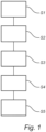
- Fig. 1 is a flow chart outlining the general steps of a method of controlling a vehicle battery management system 100 according to an embodiment of the invention. The method of Fig. 1 will be described with further reference to the vehicle 110 comprising a battery management system 100 illustrated in Fig. 2 .
- the battery management system comprises a battery 102 and a battery control unit 104 configured to control the battery 102.
- the battery control unit 104 may be a dedicated control unit configured to control a battery in a hybrid or electrical propulsion system of a vehicle, or it may be a general purpose control unit.
- the battery control unit 104 may include a microprocessor, microcontroller, programmable digital signal processor or another programmable device.
- the battery control unit 104 comprises electronic circuits and connections (not shown) as well as processing circuitry (not shown).
- the battery control unit 204 may comprise modules in either hardware or software, or partially in hardware or software and communicate using known transmission buses such as CAN-bus and/or wireless communication capabilities.
- the processing circuitry may be a general purpose processor or a specific processor.
- the battery control unit 104 comprises a non-transitory memory for storing computer program code and data upon. Thus, the skilled addressee realizes that the battery control unit 104 may be embodied by many different constructions.
- the method comprises, in the battery control unit 104, measuring S1 at least one time varying battery sensor output of the battery 102, where the sensor output is a current (I), a voltage (V), or a temperature (T). Based on the measured battery sensor output, a battery state can be determined S2.
- the method comprises updating S3 the battery model based on the determined battery state, thereby forming an updated battery model.
- the battery management system 100 receives S4 a second battery model; and finally, the received second model is combined S5 with the existing battery model, in order to form a resulting combined battery model.
- battery property here encompasses both a directly measured time varying property as well as a determined, calculated, battery property.
- a measured property is further referred to as a sensor output, and a calculated, i.e. determined, battery property is referred to as a battery state.
- a sensor output can be a measured current, voltage or temperature, which can be measured using dedicated sensors or other instruments in the battery management system.
- step of receiving S4 a second battery model may equally well be performed prior to the step of measuring S1 a battery sensor output.
- Fig. 2 further illustrates vehicles 110, 112 comprising the battery control system.
- the illustrated vehicle is a bus.
- the described method and system may equally well be used in other types of vehicles, e.g. trucks, construction equipment, cars etc.
- the battery management system comprises a first battery 102 and a first battery control unit 104.
- the first battery control unit 104 is configured to perform the method described above with reference to Fig. 1 .
- Fig. 2 further comprises a second vehicle 112 comprising a second battery control unit 108 controlling a second battery 106 in the second vehicle 112.
- the second battery model can be received from the second battery control unit 108. It can be assumed that the second battery model describes a relation between the same battery state and time varying battery property as the first battery model does. In other words, a battery model in the first vehicle 110 is updated using a battery model from the second vehicle 112.
- each vehicle comprises communication units 120, 122, including transmitting and receiving functionality.
- a transmitter 122 of the second vehicle 112 can be configured to transmit the second battery model to the receiver 120 in the first vehicle 110 when the first and second vehicles 110, 112 are within a distance of each other allowing direct communication between the vehicles 110, 112.
- the communication units 120, 122 may for example be vehicle-to-vehicle (V2V) communication units, Bluetooth or WiFi transceivers. It is also possible that a vehicle is equipped with several different types of communication units.
- a battery control server 124 configured to receive and store the updated battery model from the first battery control unit 104, and/or from the second battery control unit 108.
- the battery control server 124 can be used to store and maintain battery models from a large number of vehicles. Thereby, a vehicle can communicate with the battery control server to receive an updated battery model based not only on one other battery, but based on a large number of batteries in different vehicles. Thereby, a more detailed battery model can be achieved since it can be assumed that batteries in different vehicle experience different operating conditions, thereby providing a more complete model.
- Figs. 3A-C schematically illustrate a battery model and how a battery model may be updated based on measured battery property and resulting determined battery state.
- the model is for simplicity illustrated as a linear model 300. It should be understood that the mathematical models determining the battery properties may be much more complex.
- the example model 300 describes state-of-charge as a function of temperature.
- the result 302 of a measurement is introduced into the model, i.e. the resulting battery state based on the measured sensor output.
- the model is updated, e.g. by means of a linear fit to the data points including the newly added data point, thereby forming an updated model 304.
- a battery model may thus start with only basic information of the battery properties and then learn empirically from measurements as well as from other batteries, based on other operating conditions of the battery.
- the battery model may for example describe a resistance R, as a function of temperature, T, state-of-charge (SoC) or state-of-health (SoH) (i.e. R(T), R(SoC), R(SoH)), battery capacity as a function of T, SoC, SoH and/or the time derivative d/dt(SoH) vs T, I, SoC etc.
- a resistance R as a function of temperature, T, state-of-charge (SoC) or state-of-health (SoH)
- SoH state-of-health
- Fig. 4 schematically illustrates a battery model in the form of a battery state map 402 in a first vehicle 110.
- the state map describes a relation between a battery state and a time varying battery property.
- the state map illustrates SoC vs temperature.
- a second state map 404 describing a relation between a battery state and a time varying battery property for a second set of battery property values is received from a second vehicle 112.
- the two state maps are combined to form a resulting combined state map 406.
- the two state maps 402, 404 does not comprise any overlapping data points, so the combined state map 406 is simply formed by adding all of the data points from one map to the other.
- the received condition map comprises data points overlapping the data points already existing in the first state map
- the overlapping data points of the second state map may simply be ignored, they may be combined with the data points of the first map by forming an average, or by forming a weighted average where either data point may be averaged using a selected weight.
Landscapes
- Engineering & Computer Science (AREA)
- Power Engineering (AREA)
- Life Sciences & Earth Sciences (AREA)
- Sustainable Development (AREA)
- Sustainable Energy (AREA)
- Transportation (AREA)
- Mechanical Engineering (AREA)
- Physics & Mathematics (AREA)
- General Physics & Mathematics (AREA)
- Electric Propulsion And Braking For Vehicles (AREA)
- Secondary Cells (AREA)
Description
- A battery management system for controlling a battery in a vehicle, and a method for controlling such a battery management system.
- The invention can be applied in heavy-duty vehicles, such as trucks, buses and construction equipment. Although the invention will be described with respect to a bus, the invention is not restricted to this particular vehicle, but may also be used in other vehicles such as cars as well as heavy-duty vehicles.
- In a hybrid or electric vehicles, it is important to have a good knowledge of battery properties for various operating conditions. To achieve that, an electric vehicle often comprises a battery management system tasked with monitoring the status of the battery.
- In particular, objectives of the battery management system are (1), energy level state monitoring, i.e. state of charge estimation (2), power capacity state monitoring (3), maintaining of safe operation of the battery pack (4), state of health estimation and (5) ensuring that the cells in the battery pack are balanced. Sensor signals, such as voltage, current and temperature, are combined with mathematical models to achieve the previously listed objectives. The mathematical models include parameters describing cell properties such as for example resistance, capacity and open circuit voltage. Setting of these parameters is essential for efficient state monitoring. Typically the cell parameter setting is performed in a laboratory enabling good control of cell load, temperature etc.
- However, cell parameter setting is complex for example due to multidimensional relationships between parameters and operating conditions. For example, cell resistance may depend both on temperature, state of charge and current. Another reason for the complexity is battery degradation, meaning that battery properties will change over time.
US2012/0098481 describes an apparatus for charging a battery. The described charging system also includes a database for accumulating battery parameter data from a plurality of batteries and a processor for recursively updating data characterizing a model representing the battery based both on jointly measured battery voltage and current and accumulated parameter data received from the database. Finally, the apparatus has a current supply for supplying current for charging the battery as governed by the processor. - However, the described system only gives a limited view of the battery properties, and it is desirable to provide an improved and more detailed battery management system.
-
US2013/085696 discloses a method for obtaining degradation of a battery comprising the steps of collecting data of the battery and data related to the degradation of the battery; processing the collected data to obtain parameters related to the degradation of the battery; creating and updating a degradation model for the battery with the obtained parameters; and computing the degradation of the battery by using the degradation model and the parameters. -
US 2016/349330 discloses an assessment of the remaining life of the vehicle battery. An on-board device may collect information from one or more sensors or devices within the vehicle. The information may be processed to generate a data set that accurately describes the current status and operating conditions of the battery. The data set may be used to evaluate the health of the battery and make predictions regarding the future performance of the battery, which may be communicated to the driver of the vehicle. -
WO2016/082208 discloses a method in which battery data are collected and thereafter stored and analyzed off-board. Several models stored off-board are updated with measured data. The models are mapped into an off-board model and an on-board model is selected and updated on-board to correspond to the off-board model. The on-board model is thereafter used to determine battery status. - An objective of the invention is to provide a method and system for controlling a battery management system such that a more accurate battery model can be provided.
- According to a first aspect of the invention, the objective is achieved by a method of controlling a battery management system according to
claim 1. - Accordingly, there is provided a method of controlling a vehicle battery management system comprising a battery arranged in a vehicle, the battery being controlled by a battery control unit comprising a battery model describing a relation between a battery state and a time varying battery property. The method comprises, in the battery control unit: measuring at least one time varying battery sensor output; determining a battery state based on the measured battery sensor output; updating the battery model based on the measured battery property, thereby forming an updated battery model, receiving a second battery model; and combining the received second model with the existing battery model.
- In the present context, a battery property may be a directly measured time varying property, herein referred to as a sensor output, or a battery property may be a calculated, i.e. determined, time varying property, herein referred to as a battery state. A sensor output (i.e. a measured time varying property) can here be a measured current, voltage or temperature. Moreover, a battery state may depend on both directly measured battery properties as well as on calculated battery properties (i.e. other battery states), as will be exemplified in the following. A battery operating condition defines the overall properties of the battery at a given point in time. Accordingly, the battery operating condition can be said to include all of the measured and determined battery properties at a given point in time. The battery operating conditions may also include information describing parameters external to the battery, such as vehicle and environmental conditions.
- It is thus assumed that the battery management system comprises battery sensors, or the like, for measuring battery parameters such as current, voltage and temperature.
- Hereby, a method is provided which improves the accuracy of the battery model by updating the battery model based on the measured battery property, which in turn leads to a determination of a battery state, and by further updating the battery model based on a received second battery model. The battery model can thereby be dynamically updated in the vehicle, based both on properties of the battery in the vehicle and based on a second battery model which may describe battery states of other batteries, without connecting the vehicle to a charging station. This can also be referred to as experience sharing, where vehicles can share their respective battery models, and learn from other vehicles. Accordingly, more precise estimation of the battery states for varying battery operating conditions can be achieved in a vehicle, which has positive effects such as more efficient cell balancing and better battery energy utilization. Moreover, since there is no need to connect the vehicle to a charging station to update the battery model, both electric and hybrid vehicles can benefit from the described method. Furthermore, the described method includes battery properties acquired during operation of the vehicle, i.e. during use of the batteries. In addition to more precise estimation of the battery states, the estimation of battery states implicitly gives the possibility to track the battery state of health. The reason is the coupling between battery state of health and battery properties such as resistance.
- According to one embodiment of the invention, the battery model may comprise a function describing the battery state as a function of the time varying battery property. Hereby, the function itself can be updated based on the measured battery property for the given time dependent battery state. An advantage of providing a function describing the relationship is that also property values and battery states for operating conditions which are not previously experienced may be estimated. How a battery state is related to a battery property may for example be described using a polynomial function, tile coding or neural networks. However, other mathematical functions may also be used.
- According to the invention, the battery model comprises a state map describing the relation between the battery state and the time varying battery property for a range of battery property values. By means of the state map, a more complete description of a battery state for a range of battery operating conditions can be provided. Moreover, the use of a state map makes it easy to access previously estimated battery states for a known set of operating conditions since no calculations are required. Instead, the battery property can be acquired directly from the map.
- According to the invention, a first state map in the vehicle describes a relation between a battery state and a time varying battery property for a first set of battery property values, and a received second state map describes a relation between a battery state and a time varying battery property for a second set of battery property values, the first set of battery property values being different from the second set of battery property values, wherein the method comprises combining the first and second state maps. That the first set and second set of battery property values are different should in the present context be understood to mean that the maps comprise battery state values for different, non-overlapping, battery property values.
- According to one embodiment of the invention, combining the first and second state maps comprises adding battery states from the second state map to the first state map for non-overlapping battery property values. Hereby, a more complete state map for a battery can be achieved adding previously unknown battery property values to the map to form a combined state map.
- According to one embodiment, the battery model may describe a battery resistance or a battery capacity as a function of temperature, state-of-charge and/or state-of-health. Accordingly, the temperature, state-of-charge and/or state-of-health are examples of time varying battery properties, and the battery resistance and battery capacity are examples of determined battery states. Hereby, battery states can be determined for a wide range of values of the battery properties corresponding to various operating conditions of the vehicle, thus improving the accuracy of the model.
- According to a further embodiment of the invention, the battery model may describe a time derivative of a battery state-of-health as a function of temperature, state-of-charge and/or current. Accordingly, the time derivative of a battery state-of-health is the determined battery state. Moreover, by observing the time dependent behaviour of a battery state as a function of a time varying battery property, a detailed model accurately describing also dynamic properties of the battery can be provided.
- According to the invention, the second battery model is received from a second battery control unit controlling a second battery in a second vehicle. Thereby, since a battery management unit in the first vehicle can receive information from a second vehicle, the battery model in the first vehicle can be made more accurate, assuming that the batteries of the two vehicles are of the same or similar type. In particular, the second vehicle may have experienced different operating conditions in comparison to the first vehicle, thereby in turn having measured battery properties and determined battery states for other operating conditions.
- According to one embodiment of the invention, the method may further comprise transmitting the second model from a second battery control unit in a second vehicle to a first battery control unit in a first vehicle when the first and second vehicles are within a distance of each other allowing direct communication between the first and second vehicles. This is advantageous since it allows for automatically updating the battery models when vehicles having similar batteries are near each other. This may for example occur in parking lots, at distribution centers, at gas stations or even on the road as the vehicles are moving.
- According to one embodiment of the invention the transmission may be performed via vehicle-to-vehicle communication, Bluetooth or WiFi. Hereby, means of communication already existing in the vehicle may be used to update the battery model and thereby improve the battery utilization. Accordingly, the described battery management system could be retrofitted in an existing vehicle without the need for substantial modifications relating to communication capabilities.
- According to one embodiment of the invention the method may further comprise transmitting the second model from a second battery control unit in a second vehicle to a first battery control unit in a first vehicle via a battery control server. Hereby, a centralized server could gather information from a large number of vehicles, thereby describing battery states for a wide range of operating states, making updating the battery management systems even more effective.
- There is also provided a computer program comprising program code means for performing the steps of any of above described embodiments when the program is run on a computer, and a computer readable medium carrying the aforementioned computer program.
- According to a second aspect of the invention, there is provided a battery control system comprising: a first battery comprising a first battery control unit, arranged in a first vehicle, wherein the first battery control unit is configured to measure at least one time varying sensor output and to determine a battery state based on the measured battery sensor output. The first battery control unit comprises a battery model describing a relation between a battery state and a time varying battery property, wherein the first battery control unit is further configured to update the battery model based on the determined battery state to form an updated battery model; and the first battery control unit is configured to receive a second battery model; and to combine the received second battery model with the existing updated battery model.
- Further advantages and advantageous features of the invention are disclosed in the following description and in the dependent claims.
- With reference to the appended drawings, below follows a more detailed description of embodiments of the invention cited as examples.
- In the drawings:
-
Fig. 1 is a flow chart outlining the general steps of a method according to an embodiment of the invention; -
Fig. 2 schematically illustrates a vehicle comprising a battery control system according to an embodiment of the invention; -
Figs. 3A-C schematically illustrates mathematical models of a battery control system according to an embodiment of the invention; and -
Fig. 4 schematically illustrates a state map of a battery control system according to an embodiment of the invention. - In the present detailed description, various embodiments of the battery control system and method according to the present invention are mainly described with reference to heavy vehicle comprising a hybrid propulsion system in the form of a combination of battery powered electric motors and an internal combustion engine. However, it should be noted that various embodiments of the described invention are equally applicable for a wide range of hybrid and fully electrical vehicles.
-
Fig. 1 is a flow chart outlining the general steps of a method of controlling a vehiclebattery management system 100 according to an embodiment of the invention. The method ofFig. 1 will be described with further reference to thevehicle 110 comprising abattery management system 100 illustrated inFig. 2 . The battery management system comprises abattery 102 and abattery control unit 104 configured to control thebattery 102. - The
battery control unit 104 may be a dedicated control unit configured to control a battery in a hybrid or electrical propulsion system of a vehicle, or it may be a general purpose control unit. Thebattery control unit 104 may include a microprocessor, microcontroller, programmable digital signal processor or another programmable device. Thus, thebattery control unit 104 comprises electronic circuits and connections (not shown) as well as processing circuitry (not shown). The battery control unit 204 may comprise modules in either hardware or software, or partially in hardware or software and communicate using known transmission buses such as CAN-bus and/or wireless communication capabilities. The processing circuitry may be a general purpose processor or a specific processor. Thebattery control unit 104 comprises a non-transitory memory for storing computer program code and data upon. Thus, the skilled addressee realizes that thebattery control unit 104 may be embodied by many different constructions. - In a first step, the method comprises, in the
battery control unit 104, measuring S1 at least one time varying battery sensor output of thebattery 102, where the sensor output is a current (I), a voltage (V), or a temperature (T). Based on the measured battery sensor output, a battery state can be determined S2. Next, the method comprises updating S3 the battery model based on the determined battery state, thereby forming an updated battery model. In a following step, thebattery management system 100 receives S4 a second battery model; and finally, the received second model is combined S5 with the existing battery model, in order to form a resulting combined battery model. - As described earlier, the term "battery property" here encompasses both a directly measured time varying property as well as a determined, calculated, battery property. A measured property is further referred to as a sensor output, and a calculated, i.e. determined, battery property is referred to as a battery state. A sensor output can be a measured current, voltage or temperature, which can be measured using dedicated sensors or other instruments in the battery management system.
- It should be noted that the described method steps must not be performed in the precise order in which they are listed. For example, the step of receiving S4 a second battery model may equally well be performed prior to the step of measuring S1 a battery sensor output.
- In addition to the
battery management system 100,Fig. 2 further illustratesvehicles - In the
first vehicle 110, the battery management system comprises afirst battery 102 and a firstbattery control unit 104. The firstbattery control unit 104 is configured to perform the method described above with reference toFig. 1 .Fig. 2 further comprises asecond vehicle 112 comprising a secondbattery control unit 108 controlling asecond battery 106 in thesecond vehicle 112. Hereby, the second battery model can be received from the secondbattery control unit 108. It can be assumed that the second battery model describes a relation between the same battery state and time varying battery property as the first battery model does. In other words, a battery model in thefirst vehicle 110 is updated using a battery model from thesecond vehicle 112. - In order to efficiently communicate with other vehicles, each vehicle comprises
communication units transmitter 122 of thesecond vehicle 112 can be configured to transmit the second battery model to thereceiver 120 in thefirst vehicle 110 when the first andsecond vehicles vehicles communication units - As further illustrated in
Fig. 2 , communication between vehicles may take place via abattery control server 124 configured to receive and store the updated battery model from the firstbattery control unit 104, and/or from the secondbattery control unit 108. Thebattery control server 124 can be used to store and maintain battery models from a large number of vehicles. Thereby, a vehicle can communicate with the battery control server to receive an updated battery model based not only on one other battery, but based on a large number of batteries in different vehicles. Thereby, a more detailed battery model can be achieved since it can be assumed that batteries in different vehicle experience different operating conditions, thereby providing a more complete model. -
Figs. 3A-C schematically illustrate a battery model and how a battery model may be updated based on measured battery property and resulting determined battery state. InFig. 3A , the model is for simplicity illustrated as alinear model 300. It should be understood that the mathematical models determining the battery properties may be much more complex. Theexample model 300 describes state-of-charge as a function of temperature. InFig. 3B , theresult 302 of a measurement is introduced into the model, i.e. the resulting battery state based on the measured sensor output. Based on the newly determined battery state, the model is updated, e.g. by means of a linear fit to the data points including the newly added data point, thereby forming an updatedmodel 304. A battery model may thus start with only basic information of the battery properties and then learn empirically from measurements as well as from other batteries, based on other operating conditions of the battery. - The battery model may for example describe a resistance R, as a function of temperature, T, state-of-charge (SoC) or state-of-health (SoH) (i.e. R(T), R(SoC), R(SoH)), battery capacity as a function of T, SoC, SoH and/or the time derivative d/dt(SoH) vs T, I, SoC etc.
-
Fig. 4 schematically illustrates a battery model in the form of abattery state map 402 in afirst vehicle 110. The state map describes a relation between a battery state and a time varying battery property. In the present example, the state map illustrates SoC vs temperature. Asecond state map 404 describing a relation between a battery state and a time varying battery property for a second set of battery property values is received from asecond vehicle 112. Finally the two state maps are combined to form a resulting combinedstate map 406. - In the example illustrated in
Fig. 4 , the twostate maps state map 406 is simply formed by adding all of the data points from one map to the other. In a situation where the received condition map comprises data points overlapping the data points already existing in the first state map, there are a number of different ways to handle the overlapping data points. The overlapping data points of the second state map may simply be ignored, they may be combined with the data points of the first map by forming an average, or by forming a weighted average where either data point may be averaged using a selected weight. - It is to be understood that the present invention is not limited to the embodiments described above and illustrated in the drawings; rather, the skilled person will recognize that many changes and modifications may be made within the scope of the appended claims. In the claims, the word "comprising" does not exclude other elements or steps, and the indefinite article "a" or "an" does not exclude a plurality. The mere fact that certain measures are recited in mutually different dependent claims does not indicate that a combination of these measures cannot be used to advantage.
Claims (10)
- A method of controlling a vehicle battery management system (100) comprising a battery (102) arranged in a vehicle (110), the battery being controlled by a battery control unit (104) comprising a battery model describing a relation between a battery state and a time varying battery property, the method comprising, in the battery control unit (104):measuring (S1) at least one time varying battery sensor output;determining (S2) a battery state based on said measured battery sensor output;updating (S3) said battery model based on the determined battery state, thereby forming an updated battery model;characterized in that the method comprises, in the battery control unit (104):receiving (S4) a second battery model from a second battery control unit (108) controlling a second battery (106) in a second vehicle (112); andcombining (S5) the received second model with the existing battery model,wherein said battery model comprises a state map (402) describing said relation between said battery state and said time varying battery property for a range of battery property values, wherein a first state map (402) in said vehicle describes a relation between a battery state and a time varying battery property for a first set of battery property values, and wherein a received second state map (404) describes a relation between a battery state and a time varying battery property for a second set of battery property values, said first set of battery property values being different from said second set of battery property values, the method comprising combining said first and second state maps to form a resulting combined state map (406).
- The method according to claim 1, wherein said battery model comprises a function (300) describing said battery state as a function of said time varying battery property.
- The method according to claim 1 or 2, wherein combining said first and second state maps comprises adding battery states from said second state map to said first state map for non-overlapping battery property values.
- The method according to any one of the preceding claims, further comprising transmitting said second model from a second battery control unit in a second vehicle to a first battery control unit in a first vehicle when said first and second vehicles are within a distance of each other allowing direct communication between said first and second vehicles.
- The method according to any one of the preceding claims, further comprising transmitting said second model from a second battery control unit in a second vehicle to a first battery control unit in a first vehicle via a battery control server (124).
- A computer program comprising program code means for performing the steps of any of claims 1 to 5 when said program is run on a computer.
- A computer readable medium carrying a computer program comprising program code means for performing the steps of any of claims 1 to 5 when said program product is run on a computer.
- A battery management system (100) comprising:a first battery (102) comprising a first battery control unit (104), configured to be arranged in a first vehicle (110), wherein said first battery control unit is configured to measure at least one time varying battery sensor output and to determine a battery state based on said measured battery sensor output;said first battery control unit comprising a battery model describing a relation between a battery state and a time varying battery property, wherein said first battery control unit is further configured to update said battery model based on the determined battery state to form an updated battery model;characterized insaid first battery control unit being configured to receive a second battery model from a second battery control unit (108) controlling a second battery (106) in a second vehicle (112); and to combine the received second battery model with the existing updated battery model,wherein said battery model comprises a state map describing said relation between said battery state and said time varying battery property for a range of battery property values, wherein a first state map (402) in said vehicle (110) describes a relation between a battery state and a time varying battery property for a first set of battery property values, and wherein a received second state map (404) describes a relation between a battery state and a time varying battery property for a second set of battery property values, said first set being different from said second set of battery property values, the first battery control unit being configured to combine said first and second state maps to form a resulting combined state map (406).
- The system according to claim 8, wherein said battery model comprises a function (302) describing said battery state as a function of said time varying battery property.
- The system according to claim 8 or 9, wherein said first battery control unit is configured to combine said first and second state maps by adding battery states from said second state map to said first state map for non-overlapping battery property values.
Applications Claiming Priority (1)
| Application Number | Priority Date | Filing Date | Title |
|---|---|---|---|
| PCT/EP2016/082248 WO2018113962A1 (en) | 2016-12-21 | 2016-12-21 | A battery management system and a method for controlling a battery management system |
Publications (3)
| Publication Number | Publication Date |
|---|---|
| EP3559687A1 EP3559687A1 (en) | 2019-10-30 |
| EP3559687C0 EP3559687C0 (en) | 2024-08-21 |
| EP3559687B1 true EP3559687B1 (en) | 2024-08-21 |
Family
ID=57708584
Family Applications (1)
| Application Number | Title | Priority Date | Filing Date |
|---|---|---|---|
| EP16820263.8A Active EP3559687B1 (en) | 2016-12-21 | 2016-12-21 | A battery management system and a method for controlling a battery management system |
Country Status (5)
| Country | Link |
|---|---|
| US (1) | US11131715B2 (en) |
| EP (1) | EP3559687B1 (en) |
| KR (1) | KR20190100950A (en) |
| CN (1) | CN110036304B (en) |
| WO (1) | WO2018113962A1 (en) |
Families Citing this family (11)
| Publication number | Priority date | Publication date | Assignee | Title |
|---|---|---|---|---|
| JP7048519B2 (en) * | 2019-01-25 | 2022-04-05 | 本田技研工業株式会社 | Secondary battery status detection system, secondary battery status detection device and secondary battery status detection method |
| US11505086B2 (en) | 2019-07-08 | 2022-11-22 | Deere & Company | Vehicle speed control system and method of controlling retardation energy of a vehicle |
| CN115968447A (en) * | 2020-05-07 | 2023-04-14 | 齐塔拉科技公司 | Battery analysis system and method |
| KR20220075123A (en) * | 2020-11-27 | 2022-06-07 | 주식회사 커넥토 | Analysis Service System for Battery Condition of Electric Bus |
| US12012014B2 (en) * | 2021-02-10 | 2024-06-18 | Guangzhou Automobile Group Co., Ltd. | Method and apparatus for optimizing battery management system |
| EP4094979A1 (en) * | 2021-05-25 | 2022-11-30 | Volvo Truck Corporation | A method of determining a preconditioning status of a vehicle component or system |
| US11774504B2 (en) | 2021-10-04 | 2023-10-03 | Zitara Technologies, Inc. | System and method for battery management |
| US11577625B1 (en) | 2021-11-11 | 2023-02-14 | Beta Air, Llc | Systems and methods for predicting degradation of a battery for use in an electric vehicle |
| EP4409309A4 (en) | 2021-12-09 | 2025-10-22 | Zitara Tech Inc | System and method for determining a battery condition |
| WO2023112985A1 (en) * | 2021-12-16 | 2023-06-22 | 古河電気工業株式会社 | Battery status detection device, information processing system, and data collection method |
| WO2025081058A1 (en) | 2023-10-11 | 2025-04-17 | Zitara Technologies, Inc. | System and method for degradation based battery control |
Family Cites Families (21)
| Publication number | Priority date | Publication date | Assignee | Title |
|---|---|---|---|---|
| US20040081867A1 (en) | 2002-10-23 | 2004-04-29 | Edlund David J. | Distributed fuel cell network |
| JP2006025471A (en) * | 2004-07-06 | 2006-01-26 | Moric Co Ltd | Degradation determining system of battery for electric vehicle |
| US7107161B2 (en) * | 2004-11-05 | 2006-09-12 | Research In Motion Limited | Method and system for accurately reporting battery capacity |
| CN100486033C (en) | 2005-08-08 | 2009-05-06 | 丰田自动车株式会社 | Powertrain battery life predicting and warning apparatuses |
| CN101750584B (en) * | 2008-12-09 | 2013-01-02 | 易维特科技股份有限公司 | Method for real-time calculation of battery pack information for electric vehicle and electric vehicle using the method |
| JP5343168B2 (en) * | 2010-06-24 | 2013-11-13 | パナソニック株式会社 | Method and system for obtaining the degree of battery degradation |
| AU2011316798B2 (en) | 2010-10-22 | 2017-02-02 | Nucleus Scientific, Inc. | Apparatus and method for rapidly charging batteries |
| CN103033752B (en) | 2011-09-30 | 2016-01-20 | 吴昌旭 | Method for predicting and prolonging service life of battery of electric vehicle |
| US9058038B2 (en) * | 2012-03-29 | 2015-06-16 | GM Global Technology Operations LLC | Method and system for predicting vehicle battery health using a collaborative vehicle battery health model |
| AT512003A3 (en) * | 2013-01-23 | 2014-05-15 | Avl List Gmbh | Method for determining a control-technical observer for the SoC |
| EP3011351B1 (en) * | 2013-06-19 | 2017-08-16 | Volvo Truck Corporation | Method for estimating state of health of a battery in a hybrid vehicle |
| US20150066228A1 (en) | 2013-07-26 | 2015-03-05 | Peaknrg | Building Management and Appliance Control System |
| FR3016218B1 (en) * | 2014-01-03 | 2016-01-01 | Commissariat Energie Atomique | METHOD, DEVICE AND SYSTEM FOR ESTIMATING THE HEALTH CONDITION OF A BATTERY OF AN ELECTRIC OR HYBRID VEHICLE WHEN USED, AND METHOD FOR CONSTRUCTING A MODEL FOR SUCH ESTIMATION |
| US9446678B2 (en) | 2014-03-05 | 2016-09-20 | Ford Global Technologies, Llc | Battery model with robustness to cloud-specific communication issues |
| US9956887B2 (en) * | 2014-06-16 | 2018-05-01 | Ford Global Technologies, Llc | Batter capacity degradation indication |
| JP2016048617A (en) | 2014-08-27 | 2016-04-07 | 日本電気株式会社 | Information processing device, state estimation method, and program |
| KR102335296B1 (en) * | 2014-11-28 | 2021-12-06 | 로베르트 보쉬 게엠베하 | Wireless Network based Battery Management System |
| US10197631B2 (en) * | 2015-06-01 | 2019-02-05 | Verizon Patent And Licensing Inc. | Systems and methods for determining vehicle battery health |
| CN105717457B (en) * | 2016-02-03 | 2018-11-30 | 惠州市蓝微新源技术有限公司 | A method of it is analyzed using large database concept and carries out battery state-of-health estimation |
| US10328802B2 (en) * | 2016-11-11 | 2019-06-25 | Toyota Motor Engineering & Manufacturing North America, Inc. | Systems and methods for adaptive braking using brake wear data |
| US10556598B2 (en) * | 2016-11-23 | 2020-02-11 | Ge Global Sourcing Llc | Vehicle control systems and methods |
-
2016
- 2016-12-21 CN CN201680091324.8A patent/CN110036304B/en active Active
- 2016-12-21 EP EP16820263.8A patent/EP3559687B1/en active Active
- 2016-12-21 US US16/466,192 patent/US11131715B2/en active Active
- 2016-12-21 WO PCT/EP2016/082248 patent/WO2018113962A1/en not_active Ceased
- 2016-12-21 KR KR1020197021506A patent/KR20190100950A/en not_active Ceased
Also Published As
| Publication number | Publication date |
|---|---|
| KR20190100950A (en) | 2019-08-29 |
| WO2018113962A1 (en) | 2018-06-28 |
| CN110036304B (en) | 2021-08-20 |
| EP3559687C0 (en) | 2024-08-21 |
| US20200070682A1 (en) | 2020-03-05 |
| CN110036304A (en) | 2019-07-19 |
| EP3559687A1 (en) | 2019-10-30 |
| US11131715B2 (en) | 2021-09-28 |
Similar Documents
| Publication | Publication Date | Title |
|---|---|---|
| EP3559687B1 (en) | A battery management system and a method for controlling a battery management system | |
| CN107003357B (en) | Battery management system based on wireless network | |
| US11065978B2 (en) | Systems, methods, and storage media for adapting machine learning models for optimizing performance of a battery pack | |
| US11555858B2 (en) | Systems, methods, and storage media for predicting a discharge profile of a battery pack | |
| CN104890526B (en) | Vehicles, systems and methods | |
| US12558993B2 (en) | Computing system, battery deterioration predicting method, and battery deterioration predicting program | |
| CN111612205A (en) | System and method for determining a target battery charge level for a driving route | |
| KR102343974B1 (en) | Method and apparatus for determining the state of charge of a battery pack | |
| US12504481B2 (en) | Method and system for determining a remaining useful lifetime of a battery | |
| CN112786980B (en) | Management system with supervisory control for rechargeable energy storage devices in electric vehicles | |
| US11084387B2 (en) | Systems, methods, and storage media for arranging a plurality of cells in a vehicle battery pack | |
| CN113219336B (en) | Battery degradation judgment system, method and non-temporary storage medium storing program | |
| CN115047344A (en) | Power battery pack heat estimation method and device | |
| CN113829952A (en) | Battery control method and system of electric automobile and electric automobile | |
| CN114879070B (en) | A battery status evaluation method and related equipment | |
| KR20220070113A (en) | Real-time life estimation system and method of electric vehicle battery | |
| US20230314522A1 (en) | Traction battery power planning | |
| US20220024343A1 (en) | Method for operating an electrical energy store | |
| JP2014048874A (en) | Device, system, and method for diagnosing vehicle condition | |
| CN119795995A (en) | SOH correction method, cloud platform, system, device and storage medium | |
| KR20240132610A (en) | Real-time battery monitering system and its method | |
| Elwer et al. | Battery management systems for electric vehicle applications |
Legal Events
| Date | Code | Title | Description |
|---|---|---|---|
| STAA | Information on the status of an ep patent application or granted ep patent |
Free format text: STATUS: UNKNOWN |
|
| STAA | Information on the status of an ep patent application or granted ep patent |
Free format text: STATUS: THE INTERNATIONAL PUBLICATION HAS BEEN MADE |
|
| PUAI | Public reference made under article 153(3) epc to a published international application that has entered the european phase |
Free format text: ORIGINAL CODE: 0009012 |
|
| STAA | Information on the status of an ep patent application or granted ep patent |
Free format text: STATUS: REQUEST FOR EXAMINATION WAS MADE |
|
| 17P | Request for examination filed |
Effective date: 20190709 |
|
| AK | Designated contracting states |
Kind code of ref document: A1 Designated state(s): AL AT BE BG CH CY CZ DE DK EE ES FI FR GB GR HR HU IE IS IT LI LT LU LV MC MK MT NL NO PL PT RO RS SE SI SK SM TR |
|
| AX | Request for extension of the european patent |
Extension state: BA ME |
|
| DAV | Request for validation of the european patent (deleted) | ||
| DAX | Request for extension of the european patent (deleted) | ||
| STAA | Information on the status of an ep patent application or granted ep patent |
Free format text: STATUS: EXAMINATION IS IN PROGRESS |
|
| 17Q | First examination report despatched |
Effective date: 20221110 |
|
| GRAP | Despatch of communication of intention to grant a patent |
Free format text: ORIGINAL CODE: EPIDOSNIGR1 |
|
| STAA | Information on the status of an ep patent application or granted ep patent |
Free format text: STATUS: GRANT OF PATENT IS INTENDED |
|
| INTG | Intention to grant announced |
Effective date: 20240412 |
|
| GRAS | Grant fee paid |
Free format text: ORIGINAL CODE: EPIDOSNIGR3 |
|
| GRAA | (expected) grant |
Free format text: ORIGINAL CODE: 0009210 |
|
| STAA | Information on the status of an ep patent application or granted ep patent |
Free format text: STATUS: THE PATENT HAS BEEN GRANTED |
|
| AK | Designated contracting states |
Kind code of ref document: B1 Designated state(s): AL AT BE BG CH CY CZ DE DK EE ES FI FR GB GR HR HU IE IS IT LI LT LU LV MC MK MT NL NO PL PT RO RS SE SI SK SM TR |
|
| REG | Reference to a national code |
Ref country code: GB Ref legal event code: FG4D |
|
| REG | Reference to a national code |
Ref country code: CH Ref legal event code: EP |
|
| REG | Reference to a national code |
Ref country code: IE Ref legal event code: FG4D |
|
| REG | Reference to a national code |
Ref country code: DE Ref legal event code: R096 Ref document number: 602016089029 Country of ref document: DE |
|
| U01 | Request for unitary effect filed |
Effective date: 20240920 |
|
| U07 | Unitary effect registered |
Designated state(s): AT BE BG DE DK EE FI FR IT LT LU LV MT NL PT RO SE SI Effective date: 20241011 |
|
| PG25 | Lapsed in a contracting state [announced via postgrant information from national office to epo] |
Ref country code: NO Free format text: LAPSE BECAUSE OF FAILURE TO SUBMIT A TRANSLATION OF THE DESCRIPTION OR TO PAY THE FEE WITHIN THE PRESCRIBED TIME-LIMIT Effective date: 20241121 |
|
| PG25 | Lapsed in a contracting state [announced via postgrant information from national office to epo] |
Ref country code: GR Free format text: LAPSE BECAUSE OF FAILURE TO SUBMIT A TRANSLATION OF THE DESCRIPTION OR TO PAY THE FEE WITHIN THE PRESCRIBED TIME-LIMIT Effective date: 20241122 Ref country code: PL Free format text: LAPSE BECAUSE OF FAILURE TO SUBMIT A TRANSLATION OF THE DESCRIPTION OR TO PAY THE FEE WITHIN THE PRESCRIBED TIME-LIMIT Effective date: 20240821 |
|
| PG25 | Lapsed in a contracting state [announced via postgrant information from national office to epo] |
Ref country code: IS Free format text: LAPSE BECAUSE OF FAILURE TO SUBMIT A TRANSLATION OF THE DESCRIPTION OR TO PAY THE FEE WITHIN THE PRESCRIBED TIME-LIMIT Effective date: 20241221 |
|
| PG25 | Lapsed in a contracting state [announced via postgrant information from national office to epo] |
Ref country code: HR Free format text: LAPSE BECAUSE OF FAILURE TO SUBMIT A TRANSLATION OF THE DESCRIPTION OR TO PAY THE FEE WITHIN THE PRESCRIBED TIME-LIMIT Effective date: 20240821 |
|
| PG25 | Lapsed in a contracting state [announced via postgrant information from national office to epo] |
Ref country code: ES Free format text: LAPSE BECAUSE OF FAILURE TO SUBMIT A TRANSLATION OF THE DESCRIPTION OR TO PAY THE FEE WITHIN THE PRESCRIBED TIME-LIMIT Effective date: 20240821 Ref country code: RS Free format text: LAPSE BECAUSE OF FAILURE TO SUBMIT A TRANSLATION OF THE DESCRIPTION OR TO PAY THE FEE WITHIN THE PRESCRIBED TIME-LIMIT Effective date: 20241121 |
|
| U20 | Renewal fee for the european patent with unitary effect paid |
Year of fee payment: 9 Effective date: 20241225 |
|
| PG25 | Lapsed in a contracting state [announced via postgrant information from national office to epo] |
Ref country code: RS Free format text: LAPSE BECAUSE OF FAILURE TO SUBMIT A TRANSLATION OF THE DESCRIPTION OR TO PAY THE FEE WITHIN THE PRESCRIBED TIME-LIMIT Effective date: 20241121 Ref country code: PL Free format text: LAPSE BECAUSE OF FAILURE TO SUBMIT A TRANSLATION OF THE DESCRIPTION OR TO PAY THE FEE WITHIN THE PRESCRIBED TIME-LIMIT Effective date: 20240821 Ref country code: NO Free format text: LAPSE BECAUSE OF FAILURE TO SUBMIT A TRANSLATION OF THE DESCRIPTION OR TO PAY THE FEE WITHIN THE PRESCRIBED TIME-LIMIT Effective date: 20241121 Ref country code: IS Free format text: LAPSE BECAUSE OF FAILURE TO SUBMIT A TRANSLATION OF THE DESCRIPTION OR TO PAY THE FEE WITHIN THE PRESCRIBED TIME-LIMIT Effective date: 20241221 Ref country code: HR Free format text: LAPSE BECAUSE OF FAILURE TO SUBMIT A TRANSLATION OF THE DESCRIPTION OR TO PAY THE FEE WITHIN THE PRESCRIBED TIME-LIMIT Effective date: 20240821 Ref country code: GR Free format text: LAPSE BECAUSE OF FAILURE TO SUBMIT A TRANSLATION OF THE DESCRIPTION OR TO PAY THE FEE WITHIN THE PRESCRIBED TIME-LIMIT Effective date: 20241122 Ref country code: ES Free format text: LAPSE BECAUSE OF FAILURE TO SUBMIT A TRANSLATION OF THE DESCRIPTION OR TO PAY THE FEE WITHIN THE PRESCRIBED TIME-LIMIT Effective date: 20240821 |
|
| PG25 | Lapsed in a contracting state [announced via postgrant information from national office to epo] |
Ref country code: SM Free format text: LAPSE BECAUSE OF FAILURE TO SUBMIT A TRANSLATION OF THE DESCRIPTION OR TO PAY THE FEE WITHIN THE PRESCRIBED TIME-LIMIT Effective date: 20240821 |
|
| PG25 | Lapsed in a contracting state [announced via postgrant information from national office to epo] |
Ref country code: CZ Free format text: LAPSE BECAUSE OF FAILURE TO SUBMIT A TRANSLATION OF THE DESCRIPTION OR TO PAY THE FEE WITHIN THE PRESCRIBED TIME-LIMIT Effective date: 20240821 |
|
| PG25 | Lapsed in a contracting state [announced via postgrant information from national office to epo] |
Ref country code: SK Free format text: LAPSE BECAUSE OF FAILURE TO SUBMIT A TRANSLATION OF THE DESCRIPTION OR TO PAY THE FEE WITHIN THE PRESCRIBED TIME-LIMIT Effective date: 20240821 |
|
| PLBE | No opposition filed within time limit |
Free format text: ORIGINAL CODE: 0009261 |
|
| STAA | Information on the status of an ep patent application or granted ep patent |
Free format text: STATUS: NO OPPOSITION FILED WITHIN TIME LIMIT |
|
| PG25 | Lapsed in a contracting state [announced via postgrant information from national office to epo] |
Ref country code: MC Free format text: LAPSE BECAUSE OF FAILURE TO SUBMIT A TRANSLATION OF THE DESCRIPTION OR TO PAY THE FEE WITHIN THE PRESCRIBED TIME-LIMIT Effective date: 20240821 |
|
| 26N | No opposition filed |
Effective date: 20250522 |
|
| REG | Reference to a national code |
Ref country code: CH Ref legal event code: PL |
|
| GBPC | Gb: european patent ceased through non-payment of renewal fee |
Effective date: 20241221 |
|
| PG25 | Lapsed in a contracting state [announced via postgrant information from national office to epo] |
Ref country code: GB Free format text: LAPSE BECAUSE OF NON-PAYMENT OF DUE FEES Effective date: 20241221 |
|
| PG25 | Lapsed in a contracting state [announced via postgrant information from national office to epo] |
Ref country code: CH Free format text: LAPSE BECAUSE OF NON-PAYMENT OF DUE FEES Effective date: 20241231 |
|
| PG25 | Lapsed in a contracting state [announced via postgrant information from national office to epo] |
Ref country code: IE Free format text: LAPSE BECAUSE OF NON-PAYMENT OF DUE FEES Effective date: 20241221 |
|
| U20 | Renewal fee for the european patent with unitary effect paid |
Year of fee payment: 10 Effective date: 20251223 |