EP3559483B1 - Dispositif d'ecartement a rattrapage angulaire - Google Patents
Dispositif d'ecartement a rattrapage angulaire Download PDFInfo
- Publication number
- EP3559483B1 EP3559483B1 EP17837978.0A EP17837978A EP3559483B1 EP 3559483 B1 EP3559483 B1 EP 3559483B1 EP 17837978 A EP17837978 A EP 17837978A EP 3559483 B1 EP3559483 B1 EP 3559483B1
- Authority
- EP
- European Patent Office
- Prior art keywords
- support
- spacer
- ring
- spacer device
- drive ring
- Prior art date
- Legal status (The legal status is an assumption and is not a legal conclusion. Google has not performed a legal analysis and makes no representation as to the accuracy of the status listed.)
- Active
Links
- 125000006850 spacer group Chemical group 0.000 claims description 80
- 230000000717 retained effect Effects 0.000 claims description 3
- 230000000295 complement effect Effects 0.000 description 6
- 238000007373 indentation Methods 0.000 description 5
- 238000009434 installation Methods 0.000 description 5
- 210000002105 tongue Anatomy 0.000 description 5
- 238000004519 manufacturing process Methods 0.000 description 3
- 238000006073 displacement reaction Methods 0.000 description 2
- 239000000463 material Substances 0.000 description 2
- 208000031968 Cadaver Diseases 0.000 description 1
- 239000000654 additive Substances 0.000 description 1
- 230000000996 additive effect Effects 0.000 description 1
- 230000008878 coupling Effects 0.000 description 1
- 238000010168 coupling process Methods 0.000 description 1
- 238000005859 coupling reaction Methods 0.000 description 1
- 238000001125 extrusion Methods 0.000 description 1
- 229910052751 metal Inorganic materials 0.000 description 1
- 238000000465 moulding Methods 0.000 description 1
- 230000000284 resting effect Effects 0.000 description 1
- 238000010079 rubber tapping Methods 0.000 description 1
Images


Classifications
-
- F—MECHANICAL ENGINEERING; LIGHTING; HEATING; WEAPONS; BLASTING
- F16—ENGINEERING ELEMENTS AND UNITS; GENERAL MEASURES FOR PRODUCING AND MAINTAINING EFFECTIVE FUNCTIONING OF MACHINES OR INSTALLATIONS; THERMAL INSULATION IN GENERAL
- F16B—DEVICES FOR FASTENING OR SECURING CONSTRUCTIONAL ELEMENTS OR MACHINE PARTS TOGETHER, e.g. NAILS, BOLTS, CIRCLIPS, CLAMPS, CLIPS OR WEDGES; JOINTS OR JOINTING
- F16B5/00—Joining sheets or plates, e.g. panels, to one another or to strips or bars parallel to them
- F16B5/02—Joining sheets or plates, e.g. panels, to one another or to strips or bars parallel to them by means of fastening members using screw-thread
- F16B5/0216—Joining sheets or plates, e.g. panels, to one another or to strips or bars parallel to them by means of fastening members using screw-thread the position of the plates to be connected being adjustable
- F16B5/0233—Joining sheets or plates, e.g. panels, to one another or to strips or bars parallel to them by means of fastening members using screw-thread the position of the plates to be connected being adjustable allowing for adjustment perpendicular to the plane of the plates
-
- F—MECHANICAL ENGINEERING; LIGHTING; HEATING; WEAPONS; BLASTING
- F16—ENGINEERING ELEMENTS AND UNITS; GENERAL MEASURES FOR PRODUCING AND MAINTAINING EFFECTIVE FUNCTIONING OF MACHINES OR INSTALLATIONS; THERMAL INSULATION IN GENERAL
- F16B—DEVICES FOR FASTENING OR SECURING CONSTRUCTIONAL ELEMENTS OR MACHINE PARTS TOGETHER, e.g. NAILS, BOLTS, CIRCLIPS, CLAMPS, CLIPS OR WEDGES; JOINTS OR JOINTING
- F16B43/00—Washers or equivalent devices; Other devices for supporting bolt-heads or nuts
- F16B43/02—Washers or equivalent devices; Other devices for supporting bolt-heads or nuts with special provisions for engaging surfaces which are not perpendicular to a bolt axis or do not surround the bolt
Definitions
- the present invention relates to a spacing device which can be placed between two supports so as to bridge the distance between them.
- the invention finds a particular application in the automotive field, to fill the free space existing between a load-bearing element and a roof body of a vehicle and allow, for example, the fixing of roof bars on this vehicle. .
- This known spacer device comprises a fixing part intended to bear and / or to be fixed on a first support and a spacer having a bearing end intended to come into contact with a second support, placed opposite from the first.
- the fixing piece and the spacer piece are assembled together at the level of threads allowing them to be moved relative to each other in an axial direction, to allow the spacer device to be adjusted to the distance separating the two supports.
- the spacer device is made integral with a roof bar disposed on the outer face of the first support by means of a through screw.
- a bolt - washer system on the side of the exterior face of the second support makes it possible to lock the spacer device and to hold the canvas bar fixedly on the first support.
- the spacer is rotated by the roof bar fixing screw.
- Distance adjustment separating the two supports and the fixing of the roof bar (or more generally the locking of the spacer device) are carried out simultaneously. If these two functions are not perfectly coordinated, it is possible that the locking intervenes before the spacer is perfectly in place, which can lead to deforming one or the other of the supports.
- the presence of the roof bar on the side of the first support makes it necessary to work on the side of the second support, inside the vehicle, in order to adjust the spacer device.
- the small and confined space contributes to making the installation of the spacer device difficult.
- first support and the second support have an angular offset, that is to say when the opposite faces of the supports are not perfectly parallel to each other, the contacting of the spacer piece with the second support is imperfect.
- the locking of the spacer device by the fixing screw can lead to the deformation of one or the other of the supports.
- spacers are known from EP2130722 , DE102010000134 , DE202011100696U or document “Kugel-Aus Stamms-in Kas”, Antriebstechnik, veriser suverlage, Mainz, DE, Vol 33, n 11, 1/11/2014 .
- the present invention aims to overcome all or part of the aforementioned drawbacks.
- the spacer device comprises a support ring held against the spacer and retained by the attachment device of the drive ring, the support ring having a first flat face to bear on the second support , and a second face with a spherical cap receiving the bearing end with a spherical end of the spacer.
- a spacer device is intended to fill the space between a first support and a second support, arranged opposite one another.
- the term “internal face” will denote the faces of the first and of the second support which are placed opposite one another; and by “external face” the faces of the first and of the second support opposite to these internal faces.
- the distance separating the first and the second support is not precisely known, and the device of the invention precisely makes it possible to compensate for these differences which may exist from one point to another of the supports. As such, several spacers can be arranged between the supports so as to more precisely control the distance separating them over all their extents.
- these supports are plane, at least in the vicinity of the installation position of the spacer device.
- the two supports may have an angular offset and not be perfectly parallel to each other, and the present invention aims most particularly to compensate for this angular offset.
- the first and the second support each have an opening arranged vis-à-vis one another, allowing the spacing device to be placed between the two supports and allowing the passage of a locking member retained on the side. on each external face of the supports.
- the spacer device may also have the function of allowing the attachment of a complementary element on the external surface of one or the other of the supports.
- the locking member such as a through screw, also makes it possible to firmly press the complementary element against the external face of one of the supports.
- the figures 1a and 1b respectively show an exploded view and a section of a spacer device 1 according to a first embodiment according to the invention.
- the spacer device 1 comprises a fastener 2 having an internal thread or tapping 2c.
- the fixing part 2 is intended to be made integral with the first support. To this end, it may include a retaining member 2a and a support body 2b.
- the spacer device 1 can be introduced and positioned in the space between the two supports through an opening made beforehand in the first support.
- the retaining member 2a may comprise one or a plurality of flexible tabs 2a which contracts when the spacer device is introduced into the opening to abut the outer face of the first support on the support body 2b, and which retracts to lock this position.
- the fixing part 2 can also have a non-circular outer section so as to block its rotation with respect to the support, once it is in place on the first support, as is clearly visible in FIG.
- the spacer device 1 also comprises a spacer piece 3 having an external thread 3c.
- the spacer 3 and the fastener 2 are designed to be assembled to each other at their respective threads 3c, 2c.
- the rotational drive of the spacer 3 allows the two parts to be moved relative to each other in an axial direction.
- the spacer 3 has the shape of a cylinder, the thread being formed on the outer surface of this cylinder, so that it can be screwed and unscrewed on the fixing part 2.
- the spacer 3 has two ends, a first drive end 3a oriented towards the side of the fixing part 2, and a support end 3b opposite the drive end 3a.
- the support end 3b has a spherical end.
- the spacer device also comprises a support ring 5 held against the spacer, on the side of its support end 3b, and having a first flat face to bear on the second support, and a second face to spherical cap to receive the ball-tipped bearing end 3b of the spacer 3.
- the flat face of the ring 5 has the function of resting on the second support to preserve the distance separating the two supports even in the presence of forces. tending to bring them closer to each other.
- the ball-tipped bearing end 3b of the spacer 3 cooperates with the spherical cap of the bearing ring 5 to form a ball joint, allowing the bearing ring 5 to tilt and bring into contact plane its first plane face with the second support, even if the latter has an angular offset with the first support.
- the device 1 advantageously comprises a drive ring 4.
- the drive ring 4 is designed to be housed in the spacer 3, for example at inside the cylinder.
- the drive ring 4 may itself have the shape of a hollow cylinder, the external diameter of which corresponds substantially to the internal diameter of the cylinder forming the spacer 3, in order to be able to be inserted therein.
- the drive ring 4 and the spacer 3 are associated with each other so that an axial torque applied to the drive ring 4 is transmitted to the spacer 3.
- This coupling can be achieved by any means known per se, for example by giving the internal cylinder of the spacer 3 and the external cylinder of the drive ring 4 a non-circular section preventing the axial rotation of a part vis-à-vis the 'other.
- the drive ring 4 carries at least one indentation or a boss allowing, by means of a suitable tool, to apply a drive torque to the ring 4, so as to move it in rotation.
- the indentation or the boss may be formed on the internal wall of the ring 4.
- a plurality of such indentations or bosses may be arranged to form a slot, a star, a square in the driving ring 4 in order to facilitate cooperation. with the end of a tool, such as a screwdriver, and its rotational drive.
- the drive ring 4 makes it possible to drive the spacer 3 in rotation, when it is itself driven in rotation by a tool. In this way, it is possible to screw and / or unscrew the spacer 3 in the fixing part 2, and adjust the axial displacement of the spacer 3 to bring the support ring 5 into contact with the second support. .
- the drive ring 4 is provided with a hooking system 4a cooperating with an internal shoulder 5a of the support ring 5 for to join them together.
- the attachment system 4a may comprise an external shoulder 4b on the side of the end of the drive ring 4 oriented towards the support ring 5 and at least one flexible tongue 4e carrying on its surface a retaining collar 4c.
- the retaining flange 4c and the external shoulder 4b define a notch 4d allowing the internal shoulder 5a of the support ring 5 to be clipped onto the drive ring 4.
- the notch 4d and the shoulder 5a have between them a sufficient operating clearance to allow low amplitude movements of the support ring 5 with respect to the drive ring 4.
- the attachment system 4a comprises a plurality of flexible tongues 4e, defining as many 4d notches distributed over the contour of the end of the drive ring 4.
- the operating clearance is in this case present at each notch 4d and distributed all around the spherical cap.
- the drive ring 4 is provided with four tabs 4e defined by four through slots.
- the retaining flange 4c and the outer shoulder 4b are carried by each flexible tab 4e.
- the figure 3 shows a second embodiment of the spacer device, in which the slots defining the tongues 4e of the attachment system 4a do not open onto the end of the drive ring 4.
- the flange 4c retainer is carried by the flexible tab 4e.
- the outer shoulder 4b is integral with the rest of the drive ring 4.
- this ring 5 is slid along the ring. drive 4, after having introduced it from the end opposite to that carrying the attachment system 4a.
- the support end 3b of the spacer 3 may include a recess whose dimensions are sufficient to accommodate the retaining collar 4c. So, the support ring 5 can be held against the spacer 3, the spherical cap of the support ring 5 receiving the spherical end support end 3b of the spacer 3 to form a ball joint.
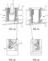
- FIG. 2a shows a sectional view of a device 1 according to the invention fixed on a first support 7a.
- a tool 6 is positioned on the side of the fixing part 2, that is to say on the side of the external face of the first support 7a on which the device 1 is fixed.
- the tool 6 has a head cooperating with bosses. or indentations formed on the internal face of the drive ring 4.
- the threads 2c, 3c with which the fasteners 2 and spacer 3 are fitted lead to the spacer 2 being axially displaced until part of the flat face of the support ring 5 comes into contact. with the second support 7b.
- This support 7b has an angular offset, which may be several degrees, with the first support 7a.
- the figure 2b shows an enlarged view of the attachment system 4a of the drive ring 4 cooperating with the shoulder 5a of the support ring 5, before this contact is made.
- the flat face of the support ring 5 ensures a flat contact with the second support 7b.
- the inclination of the support ring 5 is made possible by the ball joint formed between this support ring 5 and the ball-tipped support end 3a of the spacer 3. It is also made possible by the operating clearance existing in the attachment system 4a.
- the figure 2d shows an enlarged view of the attachment system 4a of the drive ring cooperating with the shoulder 5a of the support ring 5, after the plane contact has been made. It is observed that the game is distributed in a differentiated manner in the notches 4d forming the attachment system, so as to allow the rotation of the support ring 5.
- the spacer device 1 also serves as a support for fixing a complementary element
- the positioning and adjustment of the device 1 are carried out before positioning the complementary element, for example on the external face of the first support 7b, at the level of the fixing part 2.
- the tool 6 can therefore be introduced on this side of the support for the installation of the device 1, then the possible additional element can be fixed on the fixing part 2 during a final assembly step, for example by inserting a through-fastening screw, introduced on the side of the outer face of the second support 7b, the complementary element then forming a nut.
- the invention finds a very particular application in the automotive field, for securing a bar, forming the complementary element, on the roof of a vehicle.
- the device 1 is advantageously made of plastic material, obtained by molding or by extrusion. But it could be made of another material or be obtained by another manufacturing process, for example by additive manufacturing.
Landscapes
- Engineering & Computer Science (AREA)
- General Engineering & Computer Science (AREA)
- Mechanical Engineering (AREA)
- Connection Of Plates (AREA)
- Prostheses (AREA)
- Fittings On The Vehicle Exterior For Carrying Loads, And Devices For Holding Or Mounting Articles (AREA)
- Standing Axle, Rod, Or Tube Structures Coupled By Welding, Adhesion, Or Deposition (AREA)
Description
- La présente invention concerne un dispositif d'écartement pouvant être disposé entre deux supports de manière à combler la distance les séparant. L'invention trouve une application particulière dans le domaine de l'automobile, pour combler l'espace libre existant entre un élément porteur et une carrosserie de toit d'un véhicule et permettre, par exemple, la fixation de barres de toit sur ce véhicule.
- On connaît du document
EP2532568 un dispositif d'écartement visant à combler un espace compris entre des éléments de tôleries qui composent la structure d'un véhicule et permettant de compenser des écarts de cote pouvant exister entre ces éléments. Ce dispositif d'écartement connu comprend une pièce de fixation destinée à prendre appui et/ou à être fixée sur un premier support et une pièce d'écartement présentant une extrémité d'appui destinée à entrer en contact avec un second support, placé en regard du premier. La pièce de fixation et la pièce d'écartement sont assemblées entre elles au niveau de filetages permettant de les déplacer l'une par rapport à l'autre selon une direction axiale, pour permettre d'ajuster le dispositif d'écartement à la distance séparant les deux supports. - Dans ce document cité, le dispositif d'écartement est rendu solidaire d'une barre de toit disposée sur la face extérieure du premier support par l'intermédiaire d'une vis traversant. Un système boulon - rondelle du côté de la face extérieure du second support permet de verrouiller le dispositif d'écartement et de maintenir fixement la barre de toile sur le premier support.
- La pièce d'écartement est entraînée en rotation par la vis de fixation de la barre de toit. L'ajustement à la distance séparant les deux supports et la fixation de la barre de toit (ou plus généralement le verrouillage du dispositif d'écartement) sont réalisés simultanément. Si ces deux fonctions ne sont pas parfaitement coordonnées, il est possible que le verrouillage intervienne avant que la pièce d'écartement ne soit parfaitement en place, ce qui peut conduire à déformer l'un ou l'autre des supports.
- Par ailleurs, la présence de la barre de toit du côté du premier support impose de travailler du côté du second support, à l'intérieur du véhicule, pour régler le dispositif d'écartement. L'espace réduit et confiné contribue à rendre l'installation du dispositif d'écartement malaisé.
- Enfin, lorsque le premier support et le second support présentent un décalage angulaire, c'est à dire lorsque les faces en regard des supports ne sont pas parfaitement parallèles l'une à l'autre, la mise en contact de la pièce d'écartement avec le second support est imparfaite. Dans ce cas, le verrouillage du dispositif d'écartement par la vis de fixation peut conduire à la déformation de l'un ou l'autre des supports.
- D'autres formes de dispositifs d'écartement sont connus de
EP2130722 ,DE102010000134 ,DE202011100696U ou du document « Kugel-Ausgleichs-scheibe Kas », Antriebstechnik, Vereinigte Fachverlage, Mainz, DE, Vol 33, n 11, 1/11/2014. - La présente invention vise à pallier tout ou partie des inconvénients précités.
- En vue de la réalisation de ce but, l'objet de l'invention propose un dispositif d'écartement à rattrapage angulaire pour combler l'espace séparant un premier support d'un second support disposé en regard du premier support, le dispositif d'écartement comprenant :
- une pièce de fixation destinée à être rendue solidaire du premier support et présentant un filetage interne ;
- une pièce d'écartement présentant un filetage externe et une extrémité d'appui à bout sphérique;
- une bague d'entrainement comprenant un système d'accroche, la bague d'entrainement étant logée dans la pièce d'écartement et couplée à cette pièce ;
- Le dispositif d'écartement comprend une bague d'appui maintenue contre la pièce d'écartement et retenue par le dispositif d'accroche de la bague d'entrainement, la bague d'appui présentant une première face plane pour prendre appui sur le second support, et une seconde face à calotte sphérique recevant l'extrémité d'appui à bout sphérique de la pièce d'écartement.
- Selon d'autres caractéristiques avantageuses et non limitatives de l'invention, prises seules ou selon toute combinaison techniquement réalisable :
- la bague d'entraînement est munie d'au moins moins un bossage ou d'au moins une empreinte pour faciliter l'application d'un couple de rotation par un outil ;
- le système d'accroche et la bague d'appui présentent un jeu de fonctionnement suffisant pour permettre un mouvement de la bague d'appui ;
- le système d'accroche est formé d'au moins un cran pour recevoir un épaulement interne de la bague d'appui ;
- le cran est défini par un épaulement externe et une collerette de retenue portée par une languette flexible ;
- l'épaulement externe est porté par la languette flexible ;
- la pièce de fixation comprend un corps d'appui et un organe de retenue permettant de solidariser le dispositif au premier support.
- D'autres caractéristiques et avantages de l'invention ressortiront de la description détaillée de l'invention qui va suivre en référence aux figures annexées sur lesquels :
- les
figures 1a et 1b représentent respectivement en vue éclatée et en coupe un dispositif d'écartement selon un premier mode de réalisation et conforme à l'invention ; - les
figures 2a à 2d représentent les différentes étapes de la mise en place d'un exemple particulier du dispositif d'écartement de l'invention ; - la
figure 3 représente une vue éclatée d'un dispositif d'écartement suivant un deuxième mode de réalisation et conforme à l'invention. - Un dispositif d'écartement conforme à l'invention est destiné à combler l'espace compris entre un premier support et un second support, disposés en regard l'un de l'autre. On désignera par le terme « face interne », les faces du premier et du second support qui sont placées en vis-à-vis l'une de l'autre ; et par « face externe » les faces du premier et du second support opposées à ces faces internes. La distance séparant le premier et le second support n'est pas précisément connue, et le dispositif de l'invention permet justement de compenser ces écarts pouvant exister d'un point à l'autre des supports. À ce titre, plusieurs dispositifs d'écartement peuvent être disposés entre les supports de sorte à contrôler plus précisément la distance les séparant sur toutes leurs étendues.
- Usuellement, ces supports sont plans, au moins dans le voisinage de la position d'implantation du dispositif d'écartement. Les deux supports peuvent présenter un décalage angulaire et n'être pas parfaitement parallèles entre eux, et la présente invention vise tout particulièrement à compenser ce décalage angulaire.
- Le premier et le second support présentent chacun une ouverture disposée en vis-à-vis l'une de l'autre, permettant de placer le dispositif d'écartement entre les deux supports et permettant le passage d'un organe de verrouillage retenu du coté de chaque face externe des supports. Le dispositif d'écartement peut également avoir pour fonction de permettre la solidarisation d'un élément complémentaire sur la surface externe de l'un ou l'autre des supports. Dans ce cas, l'organe de verrouillage, tel qu'une vis traversante, permet également de fermement plaquer l'élément complémentaire contre la face externe de l'un des supports.
- Les
figures 1a et 1b représentent respectivement une vue éclatée et une coupe d'un dispositif d'écartement 1 selon un premier mode de réalisation conforme à l'invention. - Le dispositif d'écartement 1 comprend une pièce de fixation 2 présentant un filetage interne ou taraudage 2c. La pièce de fixation 2 est destinée à être rendue solidaire du premier support. À cet effet, elle peut comporter un organe 2a de retenue et un corps d'appui 2b. Le dispositif d'écartement 1 peut être introduit et positionné dans l'espace compris entre les deux supports par une ouverture préalablement aménagée dans le premier support. L'organe de retenue 2a peut comprendre une ou une pluralité de pattes flexibles 2a qui se contracte lorsque le dispositif d'écartement est introduit dans l'ouverture pour mettre en butée la face externe du premier support sur le corps d'appui 2b, et qui se rétracte pour verrouiller cette position. La pièce de fixation 2 peut également présenter une section extérieure non circulaire de manière à bloquer sa rotation vis-à-vis du support, une fois mise en place sur le premier support, comme cela est bien visible sur la figure la.
- Le dispositif d'écartement 1 conforme à l'invention comprend également une pièce d'écartement 3 présentant un filetage externe 3c. La pièce d'écartement 3 et la pièce de fixation 2 sont conçues pour être assemblés l'une à l'autre au niveau de leurs filetages 3c, 2c respectifs. L'entraînement en rotation de la pièce d'écartement 3 permet de déplacer les deux pièces l'une par rapport à l'autre selon une direction axiale.
- La pièce d'écartement 3 présente une forme de cylindre, le filetage étant formé sur la surface extérieure de ce cylindre, de sorte à pouvoir être vissé et dévissé sur la pièce de fixation 2.
- La pièce d'écartement 3 présente deux extrémités, une première extrémité d'entraînement 3a orientée du côté de la pièce de fixation 2, et une extrémité d'appui 3b à l'opposé de l'extrémité d'entrainement 3a. L'extrémité d'appui 3b est à bout sphérique.
- Le dispositif d'écartement comprend également une bague d'appui 5 maintenue contre la pièce d'écartement, du côté de son extrémité d'appui 3b, et présentant une première face plane pour prendre appui sur le second support, et une seconde face à calotte sphérique pour recevoir l'extrémité d'appui à bout sphérique 3b de la pièce d'écartement 3.
- Lorsque le dispositif d'écartement 1 est disposé dans l'espace compris entre les deux supports, la face plane de la bague 5 a pour fonction de prendre appui sur le second support pour préserver la distance séparant les deux supports même en présence d'efforts tendant à les rapprocher l'un de l'autre. L'extrémité d'appui à bout sphérique 3b de la pièce d'écartement 3 coopère avec la calotte sphérique de la bague d'appui 5 pour former une rotule, permettant à la bague d'appui 5 de s'incliner et mettre en contact plan sa première face plane avec le second support, même si celui-ci présente un décalage angulaire avec le premier support.
- Pour permettre le réglage de cette prise d'appui, le dispositif 1 conforme à l'invention comporte avantageusement une bague d'entraînement 4. La bague d'entraînement 4 est conçue pour être logée dans la pièce d'écartement 3, par exemple à l'intérieur du cylindre. La bague d'entrainement 4 peut elle-même présenter la forme d'un cylindre creux dont le diamètre externe correspond sensiblement au diamètre interne du cylindre formant la pièce d'écartement 3, pour pouvoir y être insérée. La bague d'entraînement 4 et la pièce d'écartement 3 sont associées entre elles de sorte qu'un couple de rotation axial appliqué à la bague d'entraînement 4 soit transmis à la pièce d'écartement 3. Ce couplage peut être réalisé par tout moyen connu en soi, par exemple en donnant au cylindre interne de la pièce d'écartement 3 et au cylindre externe de la bague d'entrainement 4 une section non circulaire prévenant la rotation axiale d'une pièce vis-à-vis de l'autre.
- De manière avantageuse, la bague d'entrainement 4 porte au moins une empreinte ou un bossage permettant, par l'intermédiaire d'un outil adapté, d'appliquer un couple d'entraînement à la bague 4, de manière à la déplacer en rotation. L'empreinte ou le bossage peut être formé sur la paroi interne de la bague 4. Une pluralité de telles empreintes ou bossages peut être disposée pour former une fente, une étoile, un carré dans la bague d'entrainement 4 afin de faciliter la coopération avec l'extrémité d'un outil, tel qu'un tournevis, et son entraînement en rotation.
- La bague d'entraînement 4 permet d'entraîner en rotation la pièce d'écartement 3, lorsqu'elle est elle-même entrainée en rotation par un outil. On peut de la sorte, visser et/ou dévisser la pièce d'écartement 3 dans la pièce de fixation 2, et ajuster le déplacement axial de la pièce d'écartement 3 pour mettre en contact la bague d'appui 5 avec le deuxième support.
- Pour maintenir la bague d'appui 5 contre ou à proximité de la pièce d'écartement 3, la bague d'entrainement 4 est munie d'un système d'accroche 4a coopérant avec un épaulement interne 5a de la bague d'appui 5 pour les solidariser l'une à l'autre. Le système d'accroche 4a peut comprendre un épaulement externe 4b du coté de l'extrémité de la bague d'entrainement 4 orientée vers la bague d'appui 5 et au moins une languette flexible 4e portant sur sa surface une collerette de retenue 4c. La collerette de retenue 4c et l'épaulement externe 4b définissent un cran 4d permettant de clipper l'épaulement interne 5a de la bague d'appui 5 sur la bague d'entrainement 4. Le cran 4d et l'épaulement 5a présentent entre eux un jeu de fonctionnement suffisant pour permettre des mouvements de faibles amplitudes de la bague d'appui 5 vis-à-vis de la bague d'entraînement 4. Préférentiellement, le système d'accroche 4a comprend une pluralité de languettes flexibles 4e, définissant autant de crans 4d répartis sur le contour de l'extrémité de la bague d'entrainement 4. Le jeu de fonctionnement est dans ce cas présent au niveau de chaque cran 4d et réparti tout autour de la calotte sphérique.
- Dans le premier mode de réalisation de la
figure 1A , la bague d'entrainement 4 est munie de quatre languettes 4e définie par quatre fentes débouchantes. Dans ce mode de réalisation, la collerette de retenue 4c et l'épaulement externe 4b sont portés par chaque languette flexible 4e. - La
figure 3 représente un deuxième mode de réalisation du dispositif d'écartement, dans lequel les fentes définissant les languettes 4e du système d'accroche 4a ne débouchent pas sur l'extrémité de la bague d'entraînement 4. Dans ce mode de réalisation, seul la collerette de retenue 4c est portée par la languette flexible 4e. L'épaulement externe 4b est solidaire du reste de la bague d'entrainement 4. Dans ce mode de réalisation, pour clipper la bague d'appui 5 sur le système d'accroche 4a, on fait glisser cette bague 5 le long de la bague d'entrainement 4, après l'avoir introduite depuis l'extrémité opposée à celle portant le système d'accroche 4a. - Quel que soit le mode de réalisation choisi du système d'accroche 4a, l'extrémité d'appui 3b de la pièce d'écartement 3 peut comprendre un évidement dont les dimensions sont suffisantes pour accueillir la collerette de retenue 4c. Ainsi, on peut maintenir la bague d'appui 5 contre la pièce d'écartement 3, la calotte sphérique de la bague d'appui 5 recevant l'extrémité d'appui à bout sphérique 3b de la pièce d'écartement 3 pour former une rotule.
- Cette configuration avantageuse peut être mise à profit pour compenser un décalage angulaire existant entre deux supports lors de la mise en place du dispositif d'écartement 1, comme cela va être décrit en détail en référence aux
figures 2a à 2d . Lafigure 2a représente une vue en coupe d'un dispositif 1 conforme à l'invention fixé sur un premier support 7a. Un outil 6 est positionné du côté de la pièce de fixation 2, c'est-à-dire du côté de la face externe du premier support 7a sur lequel est fixé le dispositif 1. L'outil 6 présente une tête coopérant avec des bossages ou empreintes formés sur la face interne de la bague d'entraînement 4. - Le mouvement de rotation sur lui-même de l'outil 6, éventuellement complétée de son inclinaison, entraîne en rotation la bague 4 et la pièce d'écartement 3 qui lui est couplée.
- Les filetages 2c, 3c dont sont munies les pièces de fixation 2 et d'écartement 3 conduisent à déplacer axialement la pièce d'écartement 2 jusqu'à ce qu'une partie de la face plane de la bague d'appui 5 vienne en contact avec le deuxième support 7b. Ce support 7b présente un décalage angulaire, qui peut être de plusieurs degrés, avec le premier support 7a.
- La
figure 2b représente une vue agrandie du système d'accroche 4a de la bague d'entrainement 4 coopérant avec l'épaulement 5a de la bague d'appui 5, avant que ce contact ne se réalise. On observe le jeu existant entre le cran 4d et l'épaulement interne 5a qui repose dans ce cran. - Le mouvement maintenu de rotation de l'outil 6 continue à entraîner le déplacement axial de la pièce d'écartement 3, pour placer le dispositif d'écartement 1 dans une configuration finale représentée sur la
figure 2c . - Dans cette configuration, la face plane de la bague d'appui 5 assure un contact plan avec le second support 7b. L'inclinaison de la bague d'appui 5 est rendue possible par la liaison rotule formée entre cette bague d'appui 5 et l'extrémité d'appui à bout sphérique 3a de la pièce d'écartement 3. Elle est également rendue possible par le jeu de fonctionnement existant dans le système d'accroche 4a.
- La
figure 2d représente une vue agrandie du système d'accroche 4a de la bague d'entrainement coopérant avec l'épaulement 5a de la bague d'appui 5, après que le contact plan se soit réalisé. On observe que le jeu s'est réparti de manière différenciée dans les crans 4d formant le système d'accroche, de manière à permettre la rotation de la bague d'appui 5. - Lorsque le dispositif d'écartement 1 sert également de support de fixation à un élément complémentaire, la mise en place et l'ajustement du dispositif 1 se réalisent avant de positionner l'élément complémentaire, par exemple sur la face externe du premier support 7b, au niveau de la pièce de fixation 2. L'outil 6 peut donc être introduit de ce côté du support pour la mise en place du dispositif 1, puis l'éventuel élément complémentaire peut être fixé sur la pièce de fixation 2 au cours d'une étape l'assemblage final, par exemple en insérant une vis de fixation traversante, introduite du côté de la face externe du deuxième support 7b, l'élément complémentaire formant alors écrou.
- L'invention trouve une application toute particulière dans le domaine de l'automobile, pour rendre solidaire une barre, formant l'élément complémentaire, sur le toit d'un véhicule.
- Pour des raisons de facilité de fabrication et de coût, le dispositif 1 est avantageusement constitué de matière plastique, obtenu par moulage ou par extrusion. Mais il pourrait être constitué d'un autre matériau ou être obtenu par un autre procédé de fabrication, par exemple par fabrication additive.
- Bien entendu, l'invention n'est pas limitée au mode de mise en œuvre décrit et on peut y apporter des variantes de réalisation sans sortir du cadre de l'invention tel que défini par les revendications.
Claims (7)
- Dispositif d'écartement (1) à rattrapage angulaire pour combler l'espace séparant un premier support d'un second support disposé en regard du premier support, le dispositif d'écartement (1) comprenant :- une pièce de fixation (2) destinée à être rendue solidaire du premier support et présentant un filetage interne (2c);- une pièce d'écartement (3) présentant un filetage externe (3c) et une extrémité d'appui (3b) à bout sphérique;- une bague d'entrainement (4) comprenant un système d'accroche (4a), la bague d'entrainement (4) étant logée dans la pièce d'écartement (3) et couplée à cette pièce ;la pièce de fixation (2) et la pièce d'écartement (3) étant assemblées entre elles au niveau de leurs filetages respectifs (2c, 3c) et pouvant se déplacer l'une par rapport à l'autre selon une direction axiale pour ajuster le dispositif d'écartement (1) à la distance séparant les deux supports, le dispositif d'écartement comprenant une bague d'appui (5) maintenue contre la pièce d'écartement et retenue par le dispositif d'accroche (4a) de la bague d'entrainement (4), la bague d'appui (5) présentant une première face plane pour prendre appui sur le second support, et une seconde face à calotte sphérique recevant l'extrémité d'appui à bout sphérique (3b) de la pièce d'écartement.
- Dispositif d'écartement (1) selon la revendication précédente dans lequel la bague d'entraînement (4) est munie d'au moins un bossage ou d'au moins une empreinte pour faciliter l'application d'un couple de rotation par un outil.
- Dispositif d'écartement (1) selon la revendication précédente dans lequel le système d'accroche (4a) et la bague d'appui (5) présentent un jeu de fonctionnement suffisant pour permettre un mouvement la bague d'appui (5).
- Dispositif d'écartement (1) selon la revendication précédente dans lequel le système d'accroche (4a) est formé d'au moins un cran (4d) pour recevoir un épaulement interne (5c) de la bague d'appui (5).
- Dispositif d'écartement (1) selon la revendication précédente dans lequel le cran (4d) est défini par un épaulement externe (4b) et une collerette de retenue (4c) porté par une languette flexible (4e).
- Dispositif d'écartement (1) selon la revendication précédente dans lequel l'épaulement externe (4b) est porté par la languette flexible (4e).
- Dispositif d'écartement (1) selon l'une des revendications précédentes dans laquelle la pièce de fixation (2) comprend un corps d'appui (2b) et un organe de retenue (2a) permettant de solidariser le dispositif (1) au premier support.
Applications Claiming Priority (2)
| Application Number | Priority Date | Filing Date | Title |
|---|---|---|---|
| FR1663342A FR3061119B1 (fr) | 2016-12-23 | 2016-12-23 | Dispositif d’ecartement a rattrapage angulaire |
| PCT/FR2017/053838 WO2018115799A1 (fr) | 2016-12-23 | 2017-12-22 | Dispositif d'ecartement a rattrapage angulaire |
Publications (2)
| Publication Number | Publication Date |
|---|---|
| EP3559483A1 EP3559483A1 (fr) | 2019-10-30 |
| EP3559483B1 true EP3559483B1 (fr) | 2021-02-03 |
Family
ID=58162894
Family Applications (1)
| Application Number | Title | Priority Date | Filing Date |
|---|---|---|---|
| EP17837978.0A Active EP3559483B1 (fr) | 2016-12-23 | 2017-12-22 | Dispositif d'ecartement a rattrapage angulaire |
Country Status (7)
| Country | Link |
|---|---|
| US (1) | US20200191184A1 (fr) |
| EP (1) | EP3559483B1 (fr) |
| JP (1) | JP2020502448A (fr) |
| CN (1) | CN110234890A (fr) |
| ES (1) | ES2859523T3 (fr) |
| FR (1) | FR3061119B1 (fr) |
| WO (1) | WO2018115799A1 (fr) |
Families Citing this family (2)
| Publication number | Priority date | Publication date | Assignee | Title |
|---|---|---|---|---|
| DE202016105286U1 (de) * | 2016-09-22 | 2018-01-09 | Jörg Schwarzbich | Toleranzausgleichselement |
| DE102018119473B3 (de) * | 2018-08-10 | 2019-08-29 | Dr. Ing. H.C. F. Porsche Aktiengesellschaft | Dachrahmen und Dachstruktur eines Kraftfahrzeugs |
Family Cites Families (7)
| Publication number | Priority date | Publication date | Assignee | Title |
|---|---|---|---|---|
| DE102008026414B4 (de) * | 2008-06-02 | 2010-04-08 | Böllhoff Verbindungstechnik GmbH | Toleranzausgleichselement |
| JP4953213B2 (ja) * | 2008-08-26 | 2012-06-13 | 株式会社日本マイクロニクス | テーブル高さ調整機構及びこれを用いた高さ調整テーブル |
| DE102010000134B4 (de) * | 2010-01-20 | 2023-11-30 | Witte Automotive Gmbh | Abstandsverschraubungselement für Leichtbauformteile |
| DE202011100696U1 (de) * | 2011-05-13 | 2011-07-15 | WKW Erbslöh Automotive GmbH | Toleranzausgleichseinrichtung |
| DE202011105303U1 (de) * | 2011-09-05 | 2011-10-20 | WKW Erbslöh Automotive GmbH | Toleranzausgleichseinrichtung |
| DE102011051013A1 (de) | 2011-06-10 | 2012-12-13 | Jac Products Europe Gmbh | Vorrichtung zur Befestigung eines Anbauteils, zum Beispiel einer Reling, an einer Fahrzeugkarosserie |
| DE102011054861A1 (de) * | 2011-10-27 | 2013-05-02 | Böllhoff Verbindungstechnik GmbH | Befestigungselement mit Toleranzausgleichsfunktion |
-
2016
- 2016-12-23 FR FR1663342A patent/FR3061119B1/fr active Active
-
2017
- 2017-12-22 WO PCT/FR2017/053838 patent/WO2018115799A1/fr unknown
- 2017-12-22 CN CN201780079010.0A patent/CN110234890A/zh active Pending
- 2017-12-22 ES ES17837978T patent/ES2859523T3/es active Active
- 2017-12-22 EP EP17837978.0A patent/EP3559483B1/fr active Active
- 2017-12-22 US US16/472,814 patent/US20200191184A1/en not_active Abandoned
- 2017-12-22 JP JP2019534276A patent/JP2020502448A/ja not_active Withdrawn
Non-Patent Citations (1)
| Title |
|---|
| None * |
Also Published As
| Publication number | Publication date |
|---|---|
| JP2020502448A (ja) | 2020-01-23 |
| CN110234890A (zh) | 2019-09-13 |
| WO2018115799A1 (fr) | 2018-06-28 |
| EP3559483A1 (fr) | 2019-10-30 |
| US20200191184A1 (en) | 2020-06-18 |
| FR3061119B1 (fr) | 2019-06-21 |
| ES2859523T3 (es) | 2021-10-04 |
| FR3061119A1 (fr) | 2018-06-29 |
Similar Documents
| Publication | Publication Date | Title |
|---|---|---|
| EP3546685B1 (fr) | Dispositif d'ajustement de l'elevation d'une piece | |
| EP1963688B1 (fr) | Agencement pour l'assemblage de deux pieces par vissage par l'intermediaire d'un ensemble vis-ecrou | |
| EP3546686B1 (fr) | Dispositif de l'ajustement de l'élévation d'une pièce | |
| EP2505855B1 (fr) | Fixation aveugle équipée d'un système de maintien auto-cassant | |
| EP3559483B1 (fr) | Dispositif d'ecartement a rattrapage angulaire | |
| EP3298286B1 (fr) | Element de fixation ameliore | |
| EP0402198B1 (fr) | Ensemble d'écrou à verrouillage | |
| FR2967229A1 (fr) | Dispositif de raccordement securise de deux embouts, notamment d'une canalisation. | |
| EP2502806B1 (fr) | Ensemble d'équipement de véhicule automobile et un procédé de montage associé | |
| EP1588897A1 (fr) | Elément de fixation et véhicule correspondant | |
| EP3559482B1 (fr) | Dispositif d'ecartement pouvant etre dispose entre deux supports | |
| EP3199405A1 (fr) | Barre de toit pour véhicule automobile et système de fixation associé | |
| EP1837717B1 (fr) | Pièce d'horlogerie et barillet comportant une fixation de couvercle améliorée | |
| EP4028292A1 (fr) | Maneton, boîte à rotule et système de tringlerie d'actionnement d'essuie-glaces correspondant et son procédé d'assemblage | |
| FR2911647A1 (fr) | Clip de fixation monobloc, frangible, a verrouillage "quart de tour" | |
| EP1231422A1 (fr) | Procédé pour rendre une vis imperdable, collier de fixation de tuyauteries et utilisation du procédé pour fabriquer les colliers | |
| EP3610161B1 (fr) | Attache ergonomique munie d'un pied d'encliquetage et d'un collet de compression | |
| FR2945845A1 (fr) | Dispositif de maintien d'ecrou. | |
| FR3036068A1 (fr) | Dispositif d'accrochage pour l'accrochage d'un pot d'echappement a la caisse d'un vehicule automobile | |
| EP4123187A1 (fr) | Fixation pour l'assemblage temporaire de structures | |
| EP4114693A1 (fr) | Support de boite a rotule, bielle et procede d'assemblage correspondants | |
| FR3034476A1 (fr) | Plaque de matage perfectionnee pour assemblage par vis | |
| EP4204731A1 (fr) | Dispositif de raccordement de graissage muni d'un embout de graissage et d'un porte-codeur d'identification | |
| FR3021258A3 (fr) | Plot de suspension pour element de suspension d'une ligne d'echappement de vehicule automobile | |
| FR2823264A1 (fr) | Dispositif et procede de fixation d'une piece sur un support |
Legal Events
| Date | Code | Title | Description |
|---|---|---|---|
| STAA | Information on the status of an ep patent application or granted ep patent |
Free format text: STATUS: UNKNOWN |
|
| STAA | Information on the status of an ep patent application or granted ep patent |
Free format text: STATUS: THE INTERNATIONAL PUBLICATION HAS BEEN MADE |
|
| PUAI | Public reference made under article 153(3) epc to a published international application that has entered the european phase |
Free format text: ORIGINAL CODE: 0009012 |
|
| STAA | Information on the status of an ep patent application or granted ep patent |
Free format text: STATUS: REQUEST FOR EXAMINATION WAS MADE |
|
| 17P | Request for examination filed |
Effective date: 20190611 |
|
| AK | Designated contracting states |
Kind code of ref document: A1 Designated state(s): AL AT BE BG CH CY CZ DE DK EE ES FI FR GB GR HR HU IE IS IT LI LT LU LV MC MK MT NL NO PL PT RO RS SE SI SK SM TR |
|
| AX | Request for extension of the european patent |
Extension state: BA ME |
|
| DAV | Request for validation of the european patent (deleted) | ||
| DAX | Request for extension of the european patent (deleted) | ||
| GRAP | Despatch of communication of intention to grant a patent |
Free format text: ORIGINAL CODE: EPIDOSNIGR1 |
|
| GRAJ | Information related to disapproval of communication of intention to grant by the applicant or resumption of examination proceedings by the epo deleted |
Free format text: ORIGINAL CODE: EPIDOSDIGR1 |
|
| GRAP | Despatch of communication of intention to grant a patent |
Free format text: ORIGINAL CODE: EPIDOSNIGR1 |
|
| STAA | Information on the status of an ep patent application or granted ep patent |
Free format text: STATUS: GRANT OF PATENT IS INTENDED |
|
| INTG | Intention to grant announced |
Effective date: 20200810 |
|
| GRAS | Grant fee paid |
Free format text: ORIGINAL CODE: EPIDOSNIGR3 |
|
| GRAA | (expected) grant |
Free format text: ORIGINAL CODE: 0009210 |
|
| STAA | Information on the status of an ep patent application or granted ep patent |
Free format text: STATUS: THE PATENT HAS BEEN GRANTED |
|
| AK | Designated contracting states |
Kind code of ref document: B1 Designated state(s): AL AT BE BG CH CY CZ DE DK EE ES FI FR GB GR HR HU IE IS IT LI LT LU LV MC MK MT NL NO PL PT RO RS SE SI SK SM TR |
|
| REG | Reference to a national code |
Ref country code: GB Ref legal event code: FG4D Free format text: NOT ENGLISH |
|
| REG | Reference to a national code |
Ref country code: AT Ref legal event code: REF Ref document number: 1359768 Country of ref document: AT Kind code of ref document: T Effective date: 20210215 Ref country code: CH Ref legal event code: EP |
|
| REG | Reference to a national code |
Ref country code: DE Ref legal event code: R096 Ref document number: 602017032420 Country of ref document: DE |
|
| REG | Reference to a national code |
Ref country code: IE Ref legal event code: FG4D Free format text: LANGUAGE OF EP DOCUMENT: FRENCH |
|
| REG | Reference to a national code |
Ref country code: NL Ref legal event code: MP Effective date: 20210203 |
|
| REG | Reference to a national code |
Ref country code: LT Ref legal event code: MG9D |
|
| REG | Reference to a national code |
Ref country code: AT Ref legal event code: MK05 Ref document number: 1359768 Country of ref document: AT Kind code of ref document: T Effective date: 20210203 |
|
| PG25 | Lapsed in a contracting state [announced via postgrant information from national office to epo] |
Ref country code: LT Free format text: LAPSE BECAUSE OF FAILURE TO SUBMIT A TRANSLATION OF THE DESCRIPTION OR TO PAY THE FEE WITHIN THE PRESCRIBED TIME-LIMIT Effective date: 20210203 Ref country code: BG Free format text: LAPSE BECAUSE OF FAILURE TO SUBMIT A TRANSLATION OF THE DESCRIPTION OR TO PAY THE FEE WITHIN THE PRESCRIBED TIME-LIMIT Effective date: 20210503 Ref country code: HR Free format text: LAPSE BECAUSE OF FAILURE TO SUBMIT A TRANSLATION OF THE DESCRIPTION OR TO PAY THE FEE WITHIN THE PRESCRIBED TIME-LIMIT Effective date: 20210203 Ref country code: GR Free format text: LAPSE BECAUSE OF FAILURE TO SUBMIT A TRANSLATION OF THE DESCRIPTION OR TO PAY THE FEE WITHIN THE PRESCRIBED TIME-LIMIT Effective date: 20210504 Ref country code: FI Free format text: LAPSE BECAUSE OF FAILURE TO SUBMIT A TRANSLATION OF THE DESCRIPTION OR TO PAY THE FEE WITHIN THE PRESCRIBED TIME-LIMIT Effective date: 20210203 Ref country code: PT Free format text: LAPSE BECAUSE OF FAILURE TO SUBMIT A TRANSLATION OF THE DESCRIPTION OR TO PAY THE FEE WITHIN THE PRESCRIBED TIME-LIMIT Effective date: 20210604 Ref country code: NO Free format text: LAPSE BECAUSE OF FAILURE TO SUBMIT A TRANSLATION OF THE DESCRIPTION OR TO PAY THE FEE WITHIN THE PRESCRIBED TIME-LIMIT Effective date: 20210503 |
|
| PG25 | Lapsed in a contracting state [announced via postgrant information from national office to epo] |
Ref country code: SE Free format text: LAPSE BECAUSE OF FAILURE TO SUBMIT A TRANSLATION OF THE DESCRIPTION OR TO PAY THE FEE WITHIN THE PRESCRIBED TIME-LIMIT Effective date: 20210203 Ref country code: AT Free format text: LAPSE BECAUSE OF FAILURE TO SUBMIT A TRANSLATION OF THE DESCRIPTION OR TO PAY THE FEE WITHIN THE PRESCRIBED TIME-LIMIT Effective date: 20210203 Ref country code: RS Free format text: LAPSE BECAUSE OF FAILURE TO SUBMIT A TRANSLATION OF THE DESCRIPTION OR TO PAY THE FEE WITHIN THE PRESCRIBED TIME-LIMIT Effective date: 20210203 Ref country code: LV Free format text: LAPSE BECAUSE OF FAILURE TO SUBMIT A TRANSLATION OF THE DESCRIPTION OR TO PAY THE FEE WITHIN THE PRESCRIBED TIME-LIMIT Effective date: 20210203 Ref country code: NL Free format text: LAPSE BECAUSE OF FAILURE TO SUBMIT A TRANSLATION OF THE DESCRIPTION OR TO PAY THE FEE WITHIN THE PRESCRIBED TIME-LIMIT Effective date: 20210203 Ref country code: PL Free format text: LAPSE BECAUSE OF FAILURE TO SUBMIT A TRANSLATION OF THE DESCRIPTION OR TO PAY THE FEE WITHIN THE PRESCRIBED TIME-LIMIT Effective date: 20210203 |
|
| PG25 | Lapsed in a contracting state [announced via postgrant information from national office to epo] |
Ref country code: IS Free format text: LAPSE BECAUSE OF FAILURE TO SUBMIT A TRANSLATION OF THE DESCRIPTION OR TO PAY THE FEE WITHIN THE PRESCRIBED TIME-LIMIT Effective date: 20210603 |
|
| REG | Reference to a national code |
Ref country code: ES Ref legal event code: FG2A Ref document number: 2859523 Country of ref document: ES Kind code of ref document: T3 Effective date: 20211004 |
|
| PG25 | Lapsed in a contracting state [announced via postgrant information from national office to epo] |
Ref country code: CZ Free format text: LAPSE BECAUSE OF FAILURE TO SUBMIT A TRANSLATION OF THE DESCRIPTION OR TO PAY THE FEE WITHIN THE PRESCRIBED TIME-LIMIT Effective date: 20210203 Ref country code: EE Free format text: LAPSE BECAUSE OF FAILURE TO SUBMIT A TRANSLATION OF THE DESCRIPTION OR TO PAY THE FEE WITHIN THE PRESCRIBED TIME-LIMIT Effective date: 20210203 Ref country code: SM Free format text: LAPSE BECAUSE OF FAILURE TO SUBMIT A TRANSLATION OF THE DESCRIPTION OR TO PAY THE FEE WITHIN THE PRESCRIBED TIME-LIMIT Effective date: 20210203 |
|
| REG | Reference to a national code |
Ref country code: DE Ref legal event code: R097 Ref document number: 602017032420 Country of ref document: DE |
|
| PG25 | Lapsed in a contracting state [announced via postgrant information from national office to epo] |
Ref country code: RO Free format text: LAPSE BECAUSE OF FAILURE TO SUBMIT A TRANSLATION OF THE DESCRIPTION OR TO PAY THE FEE WITHIN THE PRESCRIBED TIME-LIMIT Effective date: 20210203 Ref country code: DK Free format text: LAPSE BECAUSE OF FAILURE TO SUBMIT A TRANSLATION OF THE DESCRIPTION OR TO PAY THE FEE WITHIN THE PRESCRIBED TIME-LIMIT Effective date: 20210203 Ref country code: SK Free format text: LAPSE BECAUSE OF FAILURE TO SUBMIT A TRANSLATION OF THE DESCRIPTION OR TO PAY THE FEE WITHIN THE PRESCRIBED TIME-LIMIT Effective date: 20210203 |
|
| PLBE | No opposition filed within time limit |
Free format text: ORIGINAL CODE: 0009261 |
|
| STAA | Information on the status of an ep patent application or granted ep patent |
Free format text: STATUS: NO OPPOSITION FILED WITHIN TIME LIMIT |
|
| 26N | No opposition filed |
Effective date: 20211104 |
|
| PG25 | Lapsed in a contracting state [announced via postgrant information from national office to epo] |
Ref country code: AL Free format text: LAPSE BECAUSE OF FAILURE TO SUBMIT A TRANSLATION OF THE DESCRIPTION OR TO PAY THE FEE WITHIN THE PRESCRIBED TIME-LIMIT Effective date: 20210203 |
|
| PG25 | Lapsed in a contracting state [announced via postgrant information from national office to epo] |
Ref country code: SI Free format text: LAPSE BECAUSE OF FAILURE TO SUBMIT A TRANSLATION OF THE DESCRIPTION OR TO PAY THE FEE WITHIN THE PRESCRIBED TIME-LIMIT Effective date: 20210203 |
|
| PG25 | Lapsed in a contracting state [announced via postgrant information from national office to epo] |
Ref country code: IS Free format text: LAPSE BECAUSE OF FAILURE TO SUBMIT A TRANSLATION OF THE DESCRIPTION OR TO PAY THE FEE WITHIN THE PRESCRIBED TIME-LIMIT Effective date: 20210603 |
|
| PG25 | Lapsed in a contracting state [announced via postgrant information from national office to epo] |
Ref country code: MC Free format text: LAPSE BECAUSE OF FAILURE TO SUBMIT A TRANSLATION OF THE DESCRIPTION OR TO PAY THE FEE WITHIN THE PRESCRIBED TIME-LIMIT Effective date: 20210203 |
|
| REG | Reference to a national code |
Ref country code: CH Ref legal event code: PL |
|
| GBPC | Gb: european patent ceased through non-payment of renewal fee |
Effective date: 20211222 |
|
| REG | Reference to a national code |
Ref country code: BE Ref legal event code: MM Effective date: 20211231 |
|
| PG25 | Lapsed in a contracting state [announced via postgrant information from national office to epo] |
Ref country code: LU Free format text: LAPSE BECAUSE OF NON-PAYMENT OF DUE FEES Effective date: 20211222 Ref country code: IE Free format text: LAPSE BECAUSE OF NON-PAYMENT OF DUE FEES Effective date: 20211222 Ref country code: GB Free format text: LAPSE BECAUSE OF NON-PAYMENT OF DUE FEES Effective date: 20211222 |
|
| PG25 | Lapsed in a contracting state [announced via postgrant information from national office to epo] |
Ref country code: BE Free format text: LAPSE BECAUSE OF NON-PAYMENT OF DUE FEES Effective date: 20211231 |
|
| PG25 | Lapsed in a contracting state [announced via postgrant information from national office to epo] |
Ref country code: LI Free format text: LAPSE BECAUSE OF NON-PAYMENT OF DUE FEES Effective date: 20211231 Ref country code: CH Free format text: LAPSE BECAUSE OF NON-PAYMENT OF DUE FEES Effective date: 20211231 |
|
| PG25 | Lapsed in a contracting state [announced via postgrant information from national office to epo] |
Ref country code: CY Free format text: LAPSE BECAUSE OF FAILURE TO SUBMIT A TRANSLATION OF THE DESCRIPTION OR TO PAY THE FEE WITHIN THE PRESCRIBED TIME-LIMIT Effective date: 20210203 |
|
| P01 | Opt-out of the competence of the unified patent court (upc) registered |
Effective date: 20230526 |
|
| PG25 | Lapsed in a contracting state [announced via postgrant information from national office to epo] |
Ref country code: HU Free format text: LAPSE BECAUSE OF FAILURE TO SUBMIT A TRANSLATION OF THE DESCRIPTION OR TO PAY THE FEE WITHIN THE PRESCRIBED TIME-LIMIT; INVALID AB INITIO Effective date: 20171222 |
|
| PGFP | Annual fee paid to national office [announced via postgrant information from national office to epo] |
Ref country code: IT Payment date: 20231228 Year of fee payment: 7 Ref country code: FR Payment date: 20231222 Year of fee payment: 7 Ref country code: DE Payment date: 20231214 Year of fee payment: 7 |
|
| PGFP | Annual fee paid to national office [announced via postgrant information from national office to epo] |
Ref country code: ES Payment date: 20240130 Year of fee payment: 7 |
|
| PG25 | Lapsed in a contracting state [announced via postgrant information from national office to epo] |
Ref country code: MK Free format text: LAPSE BECAUSE OF FAILURE TO SUBMIT A TRANSLATION OF THE DESCRIPTION OR TO PAY THE FEE WITHIN THE PRESCRIBED TIME-LIMIT Effective date: 20210203 |