EP3558621B1 - Verfahren zur herstellung eines fahrradrahmens - Google Patents
Verfahren zur herstellung eines fahrradrahmens Download PDFInfo
- Publication number
- EP3558621B1 EP3558621B1 EP17800526.0A EP17800526A EP3558621B1 EP 3558621 B1 EP3558621 B1 EP 3558621B1 EP 17800526 A EP17800526 A EP 17800526A EP 3558621 B1 EP3558621 B1 EP 3558621B1
- Authority
- EP
- European Patent Office
- Prior art keywords
- injection
- modules
- module
- moulding
- cavity
- Prior art date
- Legal status (The legal status is an assumption and is not a legal conclusion. Google has not performed a legal analysis and makes no representation as to the accuracy of the status listed.)
- Active
Links
Images

















Classifications
-
- B—PERFORMING OPERATIONS; TRANSPORTING
- B29—WORKING OF PLASTICS; WORKING OF SUBSTANCES IN A PLASTIC STATE IN GENERAL
- B29C—SHAPING OR JOINING OF PLASTICS; SHAPING OF MATERIAL IN A PLASTIC STATE, NOT OTHERWISE PROVIDED FOR; AFTER-TREATMENT OF THE SHAPED PRODUCTS, e.g. REPAIRING
- B29C45/00—Injection moulding, i.e. forcing the required volume of moulding material through a nozzle into a closed mould; Apparatus therefor
- B29C45/17—Component parts, details or accessories; Auxiliary operations
- B29C45/1703—Introducing an auxiliary fluid into the mould
- B29C45/1704—Introducing an auxiliary fluid into the mould the fluid being introduced into the interior of the injected material which is still in a molten state, e.g. for producing hollow articles
-
- B—PERFORMING OPERATIONS; TRANSPORTING
- B29—WORKING OF PLASTICS; WORKING OF SUBSTANCES IN A PLASTIC STATE IN GENERAL
- B29C—SHAPING OR JOINING OF PLASTICS; SHAPING OF MATERIAL IN A PLASTIC STATE, NOT OTHERWISE PROVIDED FOR; AFTER-TREATMENT OF THE SHAPED PRODUCTS, e.g. REPAIRING
- B29C45/00—Injection moulding, i.e. forcing the required volume of moulding material through a nozzle into a closed mould; Apparatus therefor
- B29C45/14—Injection moulding, i.e. forcing the required volume of moulding material through a nozzle into a closed mould; Apparatus therefor incorporating preformed parts or layers, e.g. injection moulding around inserts or for coating articles
-
- B—PERFORMING OPERATIONS; TRANSPORTING
- B29—WORKING OF PLASTICS; WORKING OF SUBSTANCES IN A PLASTIC STATE IN GENERAL
- B29C—SHAPING OR JOINING OF PLASTICS; SHAPING OF MATERIAL IN A PLASTIC STATE, NOT OTHERWISE PROVIDED FOR; AFTER-TREATMENT OF THE SHAPED PRODUCTS, e.g. REPAIRING
- B29C45/00—Injection moulding, i.e. forcing the required volume of moulding material through a nozzle into a closed mould; Apparatus therefor
- B29C45/17—Component parts, details or accessories; Auxiliary operations
- B29C45/1703—Introducing an auxiliary fluid into the mould
- B29C45/1704—Introducing an auxiliary fluid into the mould the fluid being introduced into the interior of the injected material which is still in a molten state, e.g. for producing hollow articles
- B29C45/1711—Introducing an auxiliary fluid into the mould the fluid being introduced into the interior of the injected material which is still in a molten state, e.g. for producing hollow articles and removing excess material from the mould cavity by the introduced fluid, e.g. to an overflow cavity
-
- B—PERFORMING OPERATIONS; TRANSPORTING
- B29—WORKING OF PLASTICS; WORKING OF SUBSTANCES IN A PLASTIC STATE IN GENERAL
- B29C—SHAPING OR JOINING OF PLASTICS; SHAPING OF MATERIAL IN A PLASTIC STATE, NOT OTHERWISE PROVIDED FOR; AFTER-TREATMENT OF THE SHAPED PRODUCTS, e.g. REPAIRING
- B29C45/00—Injection moulding, i.e. forcing the required volume of moulding material through a nozzle into a closed mould; Apparatus therefor
- B29C45/17—Component parts, details or accessories; Auxiliary operations
- B29C45/26—Moulds
- B29C45/2673—Moulds with exchangeable mould parts, e.g. cassette moulds
-
- B—PERFORMING OPERATIONS; TRANSPORTING
- B62—LAND VEHICLES FOR TRAVELLING OTHERWISE THAN ON RAILS
- B62K—CYCLES; CYCLE FRAMES; CYCLE STEERING DEVICES; RIDER-OPERATED TERMINAL CONTROLS SPECIALLY ADAPTED FOR CYCLES; CYCLE AXLE SUSPENSIONS; CYCLE SIDECARS, FORECARS, OR THE LIKE
- B62K13/00—Cycles convertible to, or transformable into, other types of cycles or land vehicle
-
- B—PERFORMING OPERATIONS; TRANSPORTING
- B62—LAND VEHICLES FOR TRAVELLING OTHERWISE THAN ON RAILS
- B62K—CYCLES; CYCLE FRAMES; CYCLE STEERING DEVICES; RIDER-OPERATED TERMINAL CONTROLS SPECIALLY ADAPTED FOR CYCLES; CYCLE AXLE SUSPENSIONS; CYCLE SIDECARS, FORECARS, OR THE LIKE
- B62K19/00—Cycle frames
- B62K19/02—Cycle frames characterised by material or cross-section of frame members
- B62K19/16—Cycle frames characterised by material or cross-section of frame members the material being wholly or mainly of plastics
-
- B—PERFORMING OPERATIONS; TRANSPORTING
- B62—LAND VEHICLES FOR TRAVELLING OTHERWISE THAN ON RAILS
- B62K—CYCLES; CYCLE FRAMES; CYCLE STEERING DEVICES; RIDER-OPERATED TERMINAL CONTROLS SPECIALLY ADAPTED FOR CYCLES; CYCLE AXLE SUSPENSIONS; CYCLE SIDECARS, FORECARS, OR THE LIKE
- B62K19/00—Cycle frames
- B62K19/18—Joints between frame members
-
- B—PERFORMING OPERATIONS; TRANSPORTING
- B62—LAND VEHICLES FOR TRAVELLING OTHERWISE THAN ON RAILS
- B62K—CYCLES; CYCLE FRAMES; CYCLE STEERING DEVICES; RIDER-OPERATED TERMINAL CONTROLS SPECIALLY ADAPTED FOR CYCLES; CYCLE AXLE SUSPENSIONS; CYCLE SIDECARS, FORECARS, OR THE LIKE
- B62K3/00—Bicycles
- B62K3/02—Frames
- B62K3/04—Frames having a substantially horizontal top bar
-
- B—PERFORMING OPERATIONS; TRANSPORTING
- B62—LAND VEHICLES FOR TRAVELLING OTHERWISE THAN ON RAILS
- B62K—CYCLES; CYCLE FRAMES; CYCLE STEERING DEVICES; RIDER-OPERATED TERMINAL CONTROLS SPECIALLY ADAPTED FOR CYCLES; CYCLE AXLE SUSPENSIONS; CYCLE SIDECARS, FORECARS, OR THE LIKE
- B62K3/00—Bicycles
- B62K3/02—Frames
- B62K3/06—Frames of open type
-
- B—PERFORMING OPERATIONS; TRANSPORTING
- B62—LAND VEHICLES FOR TRAVELLING OTHERWISE THAN ON RAILS
- B62K—CYCLES; CYCLE FRAMES; CYCLE STEERING DEVICES; RIDER-OPERATED TERMINAL CONTROLS SPECIALLY ADAPTED FOR CYCLES; CYCLE AXLE SUSPENSIONS; CYCLE SIDECARS, FORECARS, OR THE LIKE
- B62K7/00—Freight- or passenger-carrying cycles
- B62K7/02—Frames
-
- B—PERFORMING OPERATIONS; TRANSPORTING
- B29—WORKING OF PLASTICS; WORKING OF SUBSTANCES IN A PLASTIC STATE IN GENERAL
- B29C—SHAPING OR JOINING OF PLASTICS; SHAPING OF MATERIAL IN A PLASTIC STATE, NOT OTHERWISE PROVIDED FOR; AFTER-TREATMENT OF THE SHAPED PRODUCTS, e.g. REPAIRING
- B29C45/00—Injection moulding, i.e. forcing the required volume of moulding material through a nozzle into a closed mould; Apparatus therefor
- B29C45/17—Component parts, details or accessories; Auxiliary operations
- B29C45/1703—Introducing an auxiliary fluid into the mould
- B29C45/1704—Introducing an auxiliary fluid into the mould the fluid being introduced into the interior of the injected material which is still in a molten state, e.g. for producing hollow articles
- B29C45/1706—Introducing an auxiliary fluid into the mould the fluid being introduced into the interior of the injected material which is still in a molten state, e.g. for producing hollow articles using particular fluids or fluid generating substances
- B29C2045/1707—Introducing an auxiliary fluid into the mould the fluid being introduced into the interior of the injected material which is still in a molten state, e.g. for producing hollow articles using particular fluids or fluid generating substances using a liquid, e.g. water
-
- B—PERFORMING OPERATIONS; TRANSPORTING
- B29—WORKING OF PLASTICS; WORKING OF SUBSTANCES IN A PLASTIC STATE IN GENERAL
- B29L—INDEXING SCHEME ASSOCIATED WITH SUBCLASS B29C, RELATING TO PARTICULAR ARTICLES
- B29L2031/00—Other particular articles
- B29L2031/30—Vehicles, e.g. ships or aircraft, or body parts thereof
- B29L2031/3091—Bicycles
-
- B—PERFORMING OPERATIONS; TRANSPORTING
- B62—LAND VEHICLES FOR TRAVELLING OTHERWISE THAN ON RAILS
- B62K—CYCLES; CYCLE FRAMES; CYCLE STEERING DEVICES; RIDER-OPERATED TERMINAL CONTROLS SPECIALLY ADAPTED FOR CYCLES; CYCLE AXLE SUSPENSIONS; CYCLE SIDECARS, FORECARS, OR THE LIKE
- B62K15/00—Collapsible or foldable cycles
- B62K2015/001—Frames adapted to be easily dismantled
Definitions
- the invention relates to a method for producing a bicycle frame from at least two modules, wherein the modules are manufactured individually and connected to one another at corresponding connecting sections.
- a special method of producing an electric bicycle is already known from the DE 10 2015 110 933 A1 known.
- the bicycle frame is manufactured there, with several individual modules being manufactured and then assembled.
- the object of the invention is to provide a concept for rationalising production and reducing production costs, which can be applied regardless of the type of frame and which is particularly advantageous when a wide range of models is to be served.
- the invention relates to a method for producing a bicycle frame from at least two modules with the features of claim 1.
- the modules are manufactured individually and connected to one another at corresponding connecting sections, and at least one of the modules is manufactured from thermoplastic using an injection molding process with fluid injection technology.
- at least two modules or all modules are manufactured from plastic using an injection molding process.
- the above and following descriptions of the module or the injection molding process can always relate to only one module or the injection molding process for producing only one module, or to two, more, or all modules or the injection molding processes for producing these multiple modules.
- the frame manufactured according to the invention can be the frame of a conventional pedal-driven bicycle or a motorized bicycle such as an electric bicycle.
- a bicycle frame is divided into at least two assemblies (modules), for example, a rear part and a front part, which can then be connected via a defined interface and preferably a cutting plane.
- the connection is preferably fixed and non-detachable.
- the modules can generally be connected by a material-to-material bond, a force-to-material bond, or a form-fitting connection.
- suitable material-to-material bonding methods include, for example, adhesive bonds or welded joints.
- suitable force-to-material bonding methods include screw connections.
- suitable form-fitting methods include, for example, riveted connections or clip connections.
- Mechanical connecting elements such as screws, sleeves, or the like can be inserted into the cavity of the injection mold and overmolded as, for example, a metallic insert during the injection molding process.
- the modules are fixed or pre-fixed to one another using a mechanical process, wherein corresponding rails are preferably molded or attached to the connecting sections of the modules and these rails are pushed into one another to fix or pre-fix the modules.
- corresponding rails are preferably molded or attached to the connecting sections of the modules and these rails are pushed into one another to fix or pre-fix the modules.
- the modules are pushed into one another along the rails up to an end position and the end position is then fixed with mechanical connecting elements such as screws or rivets.
- the rails can, for example, be formed as an integral part of the modules during the injection molding process. They can also be cast from plastic or, for example, inserted into the cavity of the injection mold as a metallic insert and overmolded.
- the modules are a front part and a rear part, with the rear part comprising the rear triangle, the seat tube and the bottom bracket, with the front part comprising the head tube, the top and/or down tube and a connecting bar running parallel to the seat tube when the modules are connected, and with the connecting sections being formed by the seat tube and the connecting bar.
- rear and front parts By combining different rear and front parts, a wide variety of models can be achieved. For example, by combining a rear part with different front parts, men's and women's versions of a bike can be created. Furthermore, by attaching different front parts to the same rear part, different types of bikes, such as cargo bikes, can be created.
- the rear part can, for example, be pre-fixed to the front part by vertical displacement.
- the final position can be fixed with a mechanical fixing element such as a pin or bolt.
- the injection molding process is carried out on an injection molding machine whose tool halves have master plates and contour plates, wherein the master plates are detachably attached to the clamping plates of the injection molding machine and wherein the contour plates are detachably attached to the master plates and form the injection molding cavity for the module.
- the cavity for the entire module is defined by two opposing contour plates.
- This design allows for cost reduction for large-scale production. This is because a separate injection mold is not required for each module variant. Instead, the same master plates can be used for similar modules, such as men's and women's versions of the front module or identical modules of different sizes to provide different frame sizes. Customization is then achieved by exchanging the contour plates. This means that the master plate can always remain attached to the injection molding machine's clamping platens, even when producing different module variants, and only needs to be removed for maintenance or repairs.
- the contour plates can be preheated to operating temperature before being attached to the clamping plate and/or equipped with all necessary connections, for example, for an injector nozzle mounted on the contour plate. This can shorten setup times when changing module variants.
- the contour plates can be connected to the base plate using a quick-clamping system.
- Suitable quick-clamping systems include mechanical, pneumatic, hydraulic, or electromagnetic quick-clamping systems.
- the injection molding process is carried out on an injection molding machine in whose cavity a replaceable insert is inserted.
- the cavity which itself is formed by interchangeable contour plates, also has an additional interchangeable insert. This further increases the flexibility in redesigning the cavity.
- Interchangeable inserts can be useful, for example, to create undercuts, to implement minor changes between module variants, to divide the cavity and produce two modules simultaneously, or to attach injection nozzles at specific positions.
- An ejection system can be provided to eject the molded module from the cavity.
- the contour plate ejection system can, for example, be self-actuated or operated by an actuator associated with the non-replaceable part of the injection molding machine.
- the ejection system can be actuated mechanically, hydraulically, pneumatically, or electromechanically.
- the contour plates and the master plates can have centering devices in the form of, for example, guide pins and corresponding holes that are aligned with the closing movement of the clamping plates.
- the centering devices can be arranged on the front and rear of the contour plates as well as on the front of the master plates. This enables fast and precise assembly as well as precise closing of the contour plates during operation.
- cones, pins, rings, and corresponding counter cavities can also serve as centering devices.
- the contour plates and/or the interchangeable inserts to be equipped with guide rails and to be pushed along these guide rails to a final position during setup of the injection molding machine.
- the contour plates and/or the interchangeable inserts can have fluid guide channels and can be cleaned before operation or cooled during operation by a fluid guide in these channels or heated. Suitable fluids include oil or water. If necessary, the fluid is introduced into the contour plate via the base plate. In this variant, the base plate has a fluid guide channel and both plates have suitable interfaces, such as quick-coupling systems.
- the contour plates and/or the interchangeable inserts can have sensors, such as pressure and/or temperature sensors, and temperature and/or pressure measurements can be performed during operation.
- the process involves inserting a film into the cavity, which is then back-injected (in-mold process).
- the contour plates and/or the interchangeable inserts may be provided with evacuation channels.
- the module comprises hollow tubes and fluid injection is carried out as part of the injection molding process.
- Suitable fluids include, for example, gas (GIT) such as nitrogen, carbon dioxide or air, water (WIT), or mixtures thereof.
- GIT gas
- WIT water
- Suitable process controls include, for example, a melt push-back process or a secondary cavity process, whereby the cavity is completely filled with a plastic melt and a liquid core is then pushed back into the screw unit or into a secondary cavity by means of a fluid or projectile.
- the secondary cavity can, for example, also be arranged in the contour plate or in the main plate. If necessary, a closing device is provided by means of which the secondary cavity is opened and closed.
- Suitable processes include so-called inflation processes, in which the component is partially filled and the melt is then inflated by a fluid.
- a hose may be present into which the fluid This avoids direct contact between the fluid and the plastic melt.
- the fluid injection is performed by an injector whose nozzle is arranged in the contour plate or in the interchangeable insert.
- the injector nozzle is preferably provided on the contour plate or the interchangeable insert, since this plate or insert defines the cavity and therefore enables direct and precise injection.
- the injectors can be positioned at the flow path end of the cavity.
- the contour plate or the interchangeable insert can be equipped with slides that cause material displacement during the process. Such slides are also referred to as core pulls.
- the slides can be actuated mechanically, hydraulically, pneumatically, or electromechanically, for example.
- At least one fiber structure, prepreg, and/or preferably a metallic insert is inserted into the injection molding cavity during the injection molding process to produce the module.
- the fiber structures can be laid or braided, for example, from long or short fibers. Carbon, glass, or even natural fibers can be considered as fiber material.
- Such inserts can impart additional rigidity to the frame.
- Other conceivable inserts for increasing rigidity include metal sheets or tubes (aluminum or steel), organic sheets, or organic sheets.
- Other suitable inserts include, for example, films for in-mold labeling, pedal and/or steering head bearings, sensors such as GPS sensors, threaded metal parts, reflectors, or cables and cable guides for electrical lines, brake lines, or fiber optics.
- a module preferably the rear part, comprises an electric motor and/or a battery. These elements or means for mounting these elements can also be inserted into the cavity as an insert. If mounting means are inserted into the cavity and overmolded, the motor and battery can be installed subsequently. In the case of a motor, the module can also include a recess into which the motor is inserted after demolding.
- the plastic is a thermoplastic.
- Suitable plastics include, for example, polyamides such as polyamide 12, polyamide 6 or polyamide 6.6, polypropylene, polyethylene, polystyrene, polyethersulfone, polyetherketone, polyphenylene sulfide, polyvinyl chloride, polyester, acrylonitrile butadiene styrene or thermoplastic elastomers.
- Preferred examples include polybutylene terephthalate or polyterephthalate ethylene.
- the plastic is injected into the injection mold in a non-crosslinked or partially crosslinked state, for example as caprolactam and optionally with an activator, and polymerized in the heated mold.
- the plastic can contain dispersed short or long fibers made of, for example, carbon or glass. This makes the frames recyclable. Adequate frame rigidity can still be achieved through suitable inserts such as fiber structures.
- a multi-component injection molding process is used to manufacture at least one module, and the component is manufactured from at least two different plastics.
- different techniques and injection molding machine designs can be used for multi-component injection molding, such as two-platen technology, three-platen technology, Indexable insert technology, indexable insert technology, stack technology, tandem technology, turnover technology and/or a rotary table tool.
- the method involves introducing a thermoplastic molten material into the closed cavity of the injection molding machine, subsequently injecting a fluid to displace the material and create a cavity, and finally opening the cavity and ejecting the finished molded component.
- a pressure higher than the ambient pressure is maintained in the cavity formed by the fluid, at least for a short time.
- fluid is circulated in the cavity formed by the fluid in order to achieve cooling. It can also be provided that the fluid is then sucked out of the cavity.
- a bicycle frame can be produced consisting of at least two separate modules which are connected to one another at corresponding connecting sections, wherein the modules are injection-molded plastic parts. Preferred embodiments will accordingly emerge from the description of the method according to the invention.
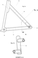
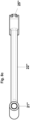
- FIG. 1 shows a module 10 of a bicycle frame according to the invention in different views.
- the module 10 represents the rear end of the frame and is suitable for assembling a diamond frame. It comprises a seat tube 11 and two of this seat tube 11, a seat stay 12, and a chain stay 13. At the lower end of the seat tube 11 there is a bore 14 for receiving the bottom bracket. At the rear ends of the stays 12 and 13 there are aligned bores 15 for receiving the rear wheel axle.
- the stays 12 and 13 are each only formed on one side. Although such a construction is rather rare in bicycles, it can be particularly advantageous for injection molding.
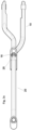
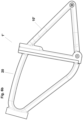
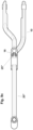
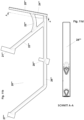
- FIG. 2 shows another module 20 of a bicycle frame according to the invention in different views.
- the module 20 depicts the main frame triangle of a diamond frame of a classic men's bicycle. It comprises a head tube 21, a top tube 22, a down tube 23, and a connecting bar 24.
- the connecting bar 24 extends between the top tube 22 and the down tube 23 in place of a seat tube and, together with them, forms the main frame triangle.
- the seat tube 11, the seat stay 12, and the chain stay 13 of module 10, as well as the head tube 21, the top tube 22, and the down tube 23 of module 20, are designed as hollow tubes, as can be seen in the figures, at least in the case of the seat tube 11, seat stay 12, chain stay 13, and head tube 21. Only the thin connecting strip 24 is solid.
- the connecting strip 24 has a rail 25 on its rear side with a web projecting from the rear side. This web extends vertically across the entire height of the connecting strip 24. It has a trapezoidal cross-section and widens with increasing distance from the rear side of the connecting strip 24.
- the seat tube 11 has a rail 16 with a groove-shaped recess on its front side. This groove extends vertically from the top of the seat tube 11 almost to its lower end. At the bottom, the rail 16 and its groove are delimited by a stop 17.
- the groove has a trapezoidal cross-section and widens with increasing depth. This cross-section of the groove corresponds to the cross-section of the web on the rail 25 of the connecting strip 24.
- the rails 16 and 25 are inserted into corresponding vertical and elongated recesses on the seat tube 11 and the connecting bar 24, as can be seen from the figures.
- the front part 20 can be connected to the rear part 10 by the web of the rail 25 of the front part 20 being positioned at the top of the groove of the rail 16 of the rear part 10 and being pushed into this groove from above until it abuts the stop 17. Lifting of the front part 20 from the rear part 10 to the front is prevented by the positive locking resulting from the corresponding trapezoidal cross-sections of the web of the rail 25 and the groove of the rail 16.
- the final position of the web of the rail 25 at the stop 17 can be secured by suitable measures such as welding or bolting, which is not specifically shown in the figure.
- Modules 10 and 11 are each manufactured by injection molding from a thermoplastic material.
- a film is first inserted into a suitable injection molding cavity, which reproduces the external shape of the modules, and then vacuum-sealed to the cavity. This film is intended to define the external appearance of the modules.
- metal parts are inserted into the injection molding cavity. These metal parts include at least the rails 16 and 25, respectively, as well as bearing rings in the bores 14 and 15.
- a thermoplastic material is then injected into the cavity, and the cavity is completely filled. The inserts and the film are back-injected. During a short holding time, the plastic material solidifies on the surfaces.
- a fluid is injected into the cavity at several points via an injector, which displaces the still-plastic plastic material in the core of the tubes, which are to be manufactured as hollow components.
- an injector which displaces the still-plastic plastic material in the core of the tubes, which are to be manufactured as hollow components.
- a mass-back injection molding process or a secondary cavity molding process can be used here.
- Holes 14 and 15, as well as the cavity in the head tube 21 and the seat post insertion area in the seat tube 11, are machined using core pulls. After cooling, modules 10 and 20 are demolded.
- Figure 4 shows a bicycle which is constructed using a frame 1 according to Figure 3 was manufactured.
- the bicycle comprises a saddle assembly 2, which is inserted from above into the seat tube 11.
- a headset 3 with a handlebar and a fork is provided, which is inserted through the head tube 21.
- the components 4, comprising the crank, chainrings, derailleur, chain, cassette, and rear derailleur, are attached to the bicycle. If metallic sleeves with internal threads are required for assembly, these can be inserted into the cavity as inserts and overmolded using the injection molding process. The necessary cables and levers on the handlebars are not shown.
- the bicycles 5 14 are attached to the front fork and to holes 15 at the rear with quick releases.
- FIG. 5 shows a further module 10' of a bicycle frame according to the invention in different views, which has a module 10 of the Figure 1 alternative rear triangle of the frame.
- the same elements are designated by the same reference numerals as before, except that an apostrophe is added.
- the only difference between the module 10' and the module 10 is the double design of both the seat stays 12a' and 12b' and the chainstays 13a' and 13b'. This design is the most common in bicycles and, for reasons of torsional rigidity, is preferred over the design according to Figure 1 preferable, but somewhat more challenging to implement in injection molding.
- This module 10' of the Figure 5 can be used with module 20 of the Figure 2 be assembled into another bicycle frame 1', which is Figure 6 and is the basis for the Figure 7 the bicycle shown.
- Figure 8 shows a further module 20" of a bicycle frame according to the invention in different views, which has a module 20 of the Figure 2 represents an alternative front section of the frame.
- the same elements are designated with the same reference numerals as before, except that two apostrophes are added.
- the only difference between the 20" module and the 20" module is the lowered top tube, so that the 20" module replicates the main frame triangle of a classic women's bike.
- This module 20" of the Figure 8 can be used with module 10 of the Figure 1 to form a 1"ladies' bicycle frame, which can be Figure 9 and is the basis for the Figure 10 The ladies' bicycle shown here.
- a module 20′′′ of a bicycle frame according to the invention is shown in different views, which has a module 20′′′ compared to the module 20 of the Figure 2 again represents an alternative front part of the frame.
- the same elements are designated by the same reference numerals as before, except that three apostrophes are added.
- the 20′′′ module represents the front part of a cargo bike, such as those often used by parents or postmen.
- the front of the top tube 22′′′ does not reach the head tube 21′′′, but instead joins the down tube 23′′′ for part of its length.
- the down tube 23′′′ does not reach all the way to the connecting bar 24′′′ at the rear, but ends shortly before it in an extension tube 26′′′, which is intended to lie under the cargo basket in the finished bicycle and extends below the down tube 23′′′ forwards beyond the position of the head tube 21′′′. It initially extends horizontally forwards and then has a bend so that the front end extends diagonally upwards.
- a front bearing tube 27′′′ is formed, which in the finished bicycle serves to accommodate a handlebarless fork for the front wheel.
- a lower control sleeve 28′′′ is formed, which is intended to accommodate a forkless headset in the finished bicycle, which can then be connected via suitable connecting means such as a rod or cable is brought into contact with the front wheel.
- This module 20′′′ of the Figure 11 can be used with module 10 of the Figure 1 be assembled into a cargo bike frame 1′′′, which is Figure 12 and is the basis for the Figure 13
- the cargo bike shown here is the one used.
- this design features a forkless headset 6′′′, which is mounted at the top in the head tube 21′′′ and at the bottom in the lower control sleeve 28′′′.
- a separate, handlebarless fork 7′′′ for securing the front wheel 5 is housed in the front bearing tube 27′′′.
- the handlebarless fork 7′′′ and the forkless headset 6′′′ are connected via a linkage 8′′′.
- a cargo container 9′′′ is provided in the area formed between the head tube 21′′′, the front bearing tube 27′′′, and the extension tube 26′′′.
- module 20′′′ of the Figure 11 with module 10' of the Figure 5 could be connected to form an alternative cargo bike frame.
- the 10', 20" and 20′′′ modules are manufactured in essentially identical manner using an injection molding process, as described above for modules 10 and 20.
- rear part modules 10 and front part modules 20 are also conceivable. It is clear that a wide variety of models can be created in this way by any combination of corresponding individual parts.
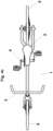
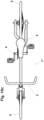
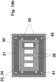
- Figure 14 shows representations of opposing clamping plates and tools of an injection molding machine for producing modules 10 and 20 of a method according to the invention.
- the representations are merely schematic, and the shape of the cavity therefore does not reflect the shape of the modules, but rather an abstract rectangular shape.
- One of the clamping plates 30 is stationary and the other can be moved along the machine axis A.
- a mounting plate 31 is provided, which is bolted to the clamping plates 30.
- the individual injection mold 32 is detachably attached to this mounting plate 31.
- Each mold half 32 comprises two separate parts, namely a main plate 33 detachably attached to the mounting plate and one detachably attached to the Contour plate 34 is attached to the main plate 33.
- Mechanical quick-clamping systems 35 (not shown in detail) can be used for the detachable fastenings.
- the cavity 36 is defined by the opposing contour plates 34.
- This two-part design of the mold halves 32 makes it possible for similar modules, for example the men's version 20 and the women's version 20" of the front part module, to be manufactured using the same main plates 33.
- similar modules for example the men's version 20 and the women's version 20" of the front part module
- the contour plates 34 when changing from the production of module 20 to the production of module 20", for example, it is not necessary to replace the entire mold halves 32; instead, only a part of them needs to be replaced, namely the contour plates 34.
- a modular principle applies.
- the relatively small contour plates 34 are cheaper to purchase than entire mold halves 32 and are also easier to replace, which results in significant advantages in production.
- the filling channels 37 for the thermoplastic mass extend through both the main plates 33 and the contour plates 34.
- the connection of the filling channel parts is achieved by aligned support with precise assembly of the contour plates 34 on the main plates 33. This precise assembly is made possible, among other things, by the assembly pins 38 on the contour plate 34 and assembly holes 39 on the main plate 33, which are each aligned in the direction of axis A.
- the contour plates 34 also have guide pins 40 and guide holes 41 on the side facing the cavity 35, which promote precise closing of the mold halves 32 during operation.
- injection nozzles (not shown in the figure) for injecting the fluid during the fluid injection process are located on the contour plates 34. These injection nozzles are positioned at the flow path end of the cavity 35. The connection of the fluid lines to the nozzles (also not shown) is arranged laterally on the contour plates 34 so that it is freely accessible and does not rest on the main plates 33. Also not shown are the Contour plates 34 arranged core pulls for forming the pipe parts described in more detail above.
- interchangeable inserts 42 are inserted into the cavity 35, which can depict detailed aspects of the modules 10 and 20, so that in some cases, when changing from the production of one type of module 10 or 20 to the production of another type of module 10 or 20, it is not even necessary to change the contour plates 34, but only to change the interchangeable inserts 42.
- the inserts 42 can, for example, be held in the cavity 36 in a form-fitting manner.
- the injection molding machine also features a mechanical ejection system 43, which is shown only in the left half. However, a similar system is also located in the other half.
- the ejection system 43 serves to eject the finished cast and solidified modules 10 and 20, respectively.
Landscapes
- Engineering & Computer Science (AREA)
- Mechanical Engineering (AREA)
- Manufacturing & Machinery (AREA)
- Injection Moulding Of Plastics Or The Like (AREA)
- Moulds For Moulding Plastics Or The Like (AREA)
Description
- Die Erfindung betrifft ein Verfahren zur Herstellung eines Fahrradrahmens aus wenigstens zwei Modulen, wobei die Module einzeln hergestellt und an korrespondierenden Verbindungsabschnitten miteinander verbunden werden.
- In der Fahrradindustrie gibt es eine große Modellvielfalt. Fast jedes Modell wird überdies auch in unterschiedlichen Größen hergestellt. Dies führt insgesamt dazu, dass sehr viele unterschiedliche Fahrradrahmen in jeweils nicht allzu großen Stückzahlen produziert werden müssen, was sich insgesamt negativ auf die Produktionskosten auswirkt.
- Vor diesem Hintergrund wäre es erstrebenswert, im Zusammenhang mit der Produktion von Fahrradrahmen eine Rationalisierung und eine Senkung der Produktionskosten zu erreichen.
- Eine besondere Methode der Produktion eines Elektrofahrrades ist bereits aus der
DE 10 2015 110 933 A1 bekannt. Dort wird der Fahrradrahmen gefertigt, dass mehrere einzelne Module gefertigt und dann zusammengesetzt werden. - Aus der
WO 2014/193245 A1 , derCN 103 552 220 A und derDE 43 28 349 A1 sind bereits Verfahren der Fluidinjektionstechnik bekannt. Aus derUS 2004/212171 A1 und derDE 10 2015 110933 A1 sind bereits modular aufgebaute Fahrradrahmen bekannt. Schließlich befasst sich dieDE 10 2012 200 594 A1 mit einem Verfahren zur Herstellung eines Fahrradrahmens, der aus recyclebarem Polymer herhergestellt ist. - Aufgabe der Erfindung ist es, ein unabhängig vom Typ des Rahmens anwendbares Konzept zur Rationalisierung der Herstellung und Senkung der Produktionskosten bereitzustellen, das insbesondere dann vorteilhaft ist, wenn eine breite Modellpalette bedient werden soll.
- Vor diesem Hintergrund betrifft die Erfindung ein Verfahren zur Herstellung eines Fahrradrahmens aus wenigstens zwei Modulen mit den Merkmalen des Anspruchs 1. Demnach werden die Module einzeln hergestellt und an korrespondierenden Verbindungsabschnitten miteinander verbunden undwenigstens eines der Module wird anhand eines Spritzgießverfahrens mit der Fluidinjektionstechnik aus thermoplastischem Kunststoff hergestellt. Vorzugsweise werden wenigstens zwei Module oder alle Module anhand eines Spritzgießverfahrens aus Kunststoff hergestellt. Die obenstehenden und nachfolgenden Beschreibungen des Moduls bzw. des Spritzgießverfahrens können jeweils immer nur ein Modul bzw. das Spritzgießverfahren zur Herstellung nur eines Moduls oder aber zwei, mehr oder alle Module bzw. die Spritzgießverfahren zur Herstellung dieser mehreren Module betreffen.
- Bei dem erfindungsgemäß hergestellten Rahmen kann es sich um den Rahmen eines herkömmlichen pedalbetriebenen Fahrrads oder eines motorisierten Fahrrads wie beispielsweise eines Elektrofahrrads handeln.
- Das erfindungsgemäße Verfahren ermöglicht eine Steigerung der Modellvielfalt und kürzere Lieferzeiten bei einer besseren ökologischen Bilanz. Bevorzugte Ausführungsformen ergeben sich aus dem Wortlaut der Ansprüche. Vorteile der Erfindung sind in den nachfolgend diskutierten bevorzugten Varianten des Verfahrens besonders ausgeprägt.
- Erfindungsgemäß ist also vorgesehen, dass ein Fahrradrahmen in wenigstens zwei Baugruppen (Module) geteilt wird, beispielsweise in ein Hinterteil und ein Vorderteil, die über eine definierte Schnittstelle und bevorzugt Schnittebene sodann verbunden werden können. Die Verbindung ist vorzugsweise fix und unlösbar.
- Die Module können grundsätzlich stoffschlüssig, kraftschlüssig oder formschlüssig verbunden werden. Konkret geeignete stoffschlüssige Verbindungsformen umfassen beispielsweise Klebeverbindungen oder Schweißverbindungen. Konkret geeignete kraftschlüssige Verbindungsformen umfassen Schraubverbindungen. Konkret geeignete formschlüssige Verbindungsformen umfassen beispielsweise Nietverbindungen oder Clipverbindungen. Mechanische Verbindungselemente wie Schrauben, Hülsen oder dergleichen können im Rahmen des Spritzgießverfahrens als beispielsweise metallisches Einlegeteil in die Kavität des Spritzgießwerkzeugs eingelegt und umspritzt werden.
- In einer Ausführungsform ist vorgesehen, dass die Module anhand eines mechanischen Verfahrens aneinander fixiert oder vorfixiert werden, wobei an den Verbindungsabschnitten der Module vorzugsweise korrespondierende Schienen angeformt oder angebracht werden und diese Schienen zur Fixierung oder Vorfixierung der Module ineinander geschoben werden. Beispielsweise kann vorgesehen sein, dass die Module entlang der Schienen bis zu einer Endstellung ineinander geschoben werden und die Endstellung dann mit mechanischen Verbindungselementen wie Schrauben oder Nieten fixiert wird. Die Schienen können beispielsweise im Rahmen des Spritzgießverfahrens als integraler Bestandteil der Module gebildet werden. Sie können ebenfalls aus Kunststoff gegossen werden oder als beispielsweise metallisches Einlegeteil in die Kavität des Spritzgießwerkzeugs eingelegt und umspritzt werden.
- In einer Ausführungsform ist vorgesehen, dass es sich bei den Modulen um ein Vorderteil und ein Hinterteil handelt, wobei das Hinterteil den Hinterbau, das Sattelrohr und das Tretlager umfasst, wobei das Vorderteil das Steuerrohr, das Ober- und/oder Unterrohr und eine im verbundenen Zustand der Module parallel zum Sattelrohr verlaufende Verbindungsleiste umfasst, und wobei die Verbindungsabschnitte durch das Sattelrohr und die Verbindungsleiste gebildet werden. Mit dieser Konstruktion kann erreicht werden, dass die beiden Module eine in etwa ähnliche Größe haben und sich der Verbindungsabschnitt über eine signifikante Länge erstreckt, sodass eine stabile Verbindung und eine ausreichende Steifigkeit des Rahmens erreicht werden können. Zusätzliche Stabilität wird durch die Zuordnung des Tretlagers zum Hinterbau erreicht, der im fertig montierten Zustand das Antriebsrad hält.
- Durch eine Kombination von verschiedenen Hinter- und Vorderteilen kann eine hohe Modellvielfalt realisiert werden. Beispielsweise lassen sich durch die Kombination eines Hinterteils mit unterschiedlichen Vorderteilen Herren- und Damenversionen eines Rads herstellen. Ferner können durch den Anbau unterschiedlicher Vorderteile an dasselbe Hinterteil auch unterschiedliche Radtypen wie beispielsweise Lastenfahrräder hergestellt werden.
- Sofern am Sattelrohr und an der Verbindungsleiste ein vertikales Schienensystem vorgesehen ist, kann beispielsweise das Hinterteil durch vertikale Verschiebung am Vorderteil vorfixiert werden die Endstellung kann mit einem mechanischen Fixierungselement wie beispielsweise einem Stift oder Bolzen fixiert werden.
- In einer Ausführungsform ist vorgesehen, dass das Spritzgießverfahren an einer Spritzgießmaschine durchgeführt wird, deren Werkzeughälften Stammplatten und Konturplatten aufweisen, wobei die Stammplatten lösbar an den Aufspannplatten der Spritzgießmaschine befestigt sind und wobei die Konturplatten lösbar an den Stammplatten befestigt sind und die Spritzgießkavität für das Modul bilden. Es kann vorgesehen sein, dass die Kavität für das gesamte Modul durch zwei gegenüberliegende Konturplatten definiert wird. Wenn hier von Werkzeughälften gesprochen wird, dann ist mit dieser Terminologie keine Beschränkung auf genau zwei Hälften beabsichtigt. Ebenfalls können drei oder mehrere "Hälften" eine Kavität bilden.
- In dieser Ausführungsform kann für große Stückzahlen eine Kostenreduktion erreicht werden. Denn es wird nicht für jede Variante eines Moduls ein insgesamt eigenes Spritzgießwerkzeug benötigt, sondern für ähnliche Module, beispielsweise Herren- und Damenausführungen des Vordermoduls oder identische Module unterschiedlicher Größe zur Bereitstellung unterschiedlicher Rahmengrößen, können dieselben Stammplatten verwendet werden. Die Individualisierung erfolgt dann durch Tausch der Konturplatten. So kann die Stammplatte auch bei der Herstellung unterschiedlicher Modulvarianten immer an den Aufspannplatten der Spritzgießmaschine befestigt bleiben und muss lediglich für Wartungen oder Reparaturen abgenommen werden.
- Die Konturplatten können vor deren Befestigung an der Aufspannplatte auf Betriebstemperatur vorgewärmt und/oder mit allen benötigten Anschlüssen, beispielsweise für eine an der Konturplatte angeordnete Injektordüse versehen werden. So können die Rüstzeiten bei einem Wechsel der Modulvarianten verkürzt werden.
- Die Konturplatten können anhand eines Schnellspannsystems mit der Stammplatte verbunden werden. Geeignete Schnellspannsysteme umfassen mechanische, pneumatische, hydraulische oder elektromagnetischen Schnellspannsysteme.
- In einer Ausführungsform ist vorgesehen, dass das Spritzgießverfahren an einer Spritzgießmaschine durchgeführt wird, in deren Kavität ein Wechseleinsatz eingelegt ist. Es kann also in einer Ausführungsform vorgesehen sein, dass in der Kavität, die selbst durch auswechselbare Konturplatten gebildet wird, noch zusätzlich ein auswechselbarer Einsatz vorhanden ist. So wird die Flexibilität in der Umgestaltung der Kavität noch weiter erhöht. Wechseleinsätze können beispielsweise sinnvoll sein, um Hinterschneidungen abzubilden, um kleinere Änderungen zwischen Modulvarianten zu realisieren, um eine Teilung der Kavität zu erreichen und zwei Module gleichzeitig produzieren zu können oder um Injektionsdüsen an bestimmten Positionen anzubringen.
- Es kann ein Auswurfsystem vorgesehen sein, mit dem das gegossene Modul aus der Kavität ausgeworfen wird. Das Auswurfsystem der Konturplatte kann beispielsweise selbstbetätigt sein oder anhand eines Aktors betätigt werden, der dem nicht wechselbaren Teil der Spritzgießmaschine zugeordnet ist. Die Betätigung des Auswurfsystems kann beispielsweise mechanisch, hydraulisch, pneumatisch oder elektromechanisch erfolgen.
- Die Konturplatten und die Stammplatten können Zentriereinrichtungen in Form von beispielsweise Führungsbolzen und korrespondierenden Löchern aufweisen, die in Richtung der Schließbewegung der Aufspannplatten stehen. Die Zentriereinrichtungen können an der Vorderseite und der Rückseite der Konturplatten sowie an der Vorderseite der Stammplatten angeordnet sein. So wird eine schnelle und präzise Montage ebenso ermöglicht wie ein präzises Schließen der Konturplatten im Betrieb. Ferner können auch beispielsweise Koni, Stifte, Ringe und entsprechende Gegenkavitäten als Zentriereinrichtungen dienen. Des Weiteren ist denkbar, dass die Konturplatten und/oder die Wechseleinsätze mit Führungsschienen ausgerüstet sind und beim Rüsten der Spritzgießmaschine an diesen Führungsschienen bis an eine Endposition aufgeschoben werden.
- Die Konturplatten und/oder die Wechseleinsätze können Fluidführungskanäle aufweisen und vor dem Betrieb oder während des Betriebs durch eine Fluidführung in diesen Kanälen gekühlt oder beheizt werden. Als geeignete Fluide kommen beispielsweise Öl oder Wasser in Betracht. Gegebenenfalls wird das Fluid über die Stammplatte in die Konturplatte eingeleitet, wobei die Stammplatte in dieser Variante einen Fluidführungskanal und beide Platten geeignete Schnittstellen wie beispielsweise Schnellkupplungssysteme aufweisen. Die Konturplatten und/oder die Wechseleinsätze können Sensoren wie beispielsweise Druck- und/oder Temperatursensoren aufweisen und dass während des Betriebs eine Temperatur- und/oder Druckmessung erfolgt.
- In einer Ausführungsform ist vorgesehen, dass im Rahmen des Verfahrens eine Folie in die Kavität eingelegt wird, die dann hinterspritzt wird (In-Mould-Verfahren). Zum Halten der Folie vor dem Hinterspritzen kann vorgesehen sein, dass die Konturplatten und/oder die Wechseleinsätze Evakuierungskanäle aufweisen.
- In einer Ausführungsform ist vorgesehen, dass das Modul hohle Rohre umfasst und im Rahmen des Spritzgießverfahrens eine Fluidinjektion durchgeführt wird. Wenn hier von einem Rohr die Rede ist, kann dieses im Querschnitt rund, oval, mehreckig oder beliebig anders geformt sein. Geeignete Fluide umfassen beispielsweise Gas (GIT) wie Stickstoff, Kohlendioxid oder Luft, Wasser (WIT) oder Mischungen daraus. Geeignete Verfahrensführungen umfassen beispielsweise ein Masserückdrück- oder ein Nebenkavitätenverfahren, wobei die Kavität vollständig mit einer Kunststoffschmelze gefüllt und eine flüssige Seele dann mittels Fluid oder Projektil zurück in das Schneckenaggregat oder in eine Nebenkavität gedrückt wird. Die Nebenkavität kann beispielsweise ebenfalls in der Konturplatte oder in der Stammplatte angeordnet sein. Gegebenenfalls ist eine Schließvorrichtung vorhanden, anhand der die Nebenkavität geöffnet und geschlossen wird.
- Weitere geeignete Verfahrensführungen umfassen sogenannte Aufblasverfahren, in denen das Bauteil teilgefüllt und die Schmelze dann durch ein Fluid aufgeblasen wird. Im Falle eines Aufblasverfahrens kann ein Schlauch vorhanden sein, in den das Fluid injiziert wird. So wird ein unmittelbarer Kontakt zwischen dem Fluid und der Kunststoffschmelze vermieden.
- In einer Ausführungsform ist vorgesehen, dass die Fluidinjektion durch einen Injektor durchgeführt wird, dessen Düse in der Konturplatte oder im Wechseleinsatz angeordnet ist. Im Falle einer Verwendung von wechselbaren Konturplatten ist die Injektordüse vorzugsweise an der Konturplatte oder am Wechseleinsatz vorgesehen, da diese Platte bzw. dieser Einsatz die Kavität definieren und daher eine unmittelbare und präzise Injektion ermöglicht wird.
- Generell kann vorgesehen sein, dass die Injektoren am Fließwegende der Kavität positioniert werden.
- Es kann vorgesehen sein, dass die Konturplatte oder der Wechseleinsatz mit Schiebern ausgerüstet sind, die im Verfahren eine Materialverschiebung bewirken. Derartige Schieber werden auch als Kernzüge bezeichnet. Die Betätigung der Schieber kann beispielsweise mechanisch, hydraulisch, pneumatisch oder elektromechanisch erfolgen.
- In einer Ausführungsform ist vorgesehen, dass im Spritzgießverfahren zur Herstellung des Moduls wenigstens ein Fasergebilde, Prepreg und/oder vorzugsweise metallisches Einlegeteil in die Spritzgießkavität eingelegt wird. Die Fasergebilde können Gelege oder Geflechte aus beispielsweise Langfasern oder Kurzfasern sein. Als Fasermaterial kommen Kohlenstoff, Glas oder auch Naturfasern in Betracht. Solche Einlegeteile können dem Rahmen zusätzliche Steifigkeit verleihen. Weitere denkbare Einlegeteile zur Erhöhung der Steifigkeit umfassen Bleche oder Rohre aus Metall (Aluminium oder Stahl), Organobleche oder Organosheets. Weitere geeignete Einlegeteile umfassen beispielsweise Folien für ein In-Mould-Labelling, Tret- und/oder Lenkkopflager, Sensoren wie beispielsweise eine GPS-Sensorik, gewindetragende Metallteile, Reflektoren oder Kabel und Kabelführungen für elektrische Leitungen, Bremsleitungen oder Lichtleiter.
- In einer Ausführungsform ist vorgesehen, dass ein Modul, vorzugsweise das Hinterteil einen Elektromotor und/oder einen Akku umfasst. Auch diese Elemente oder Mittel zur Montage dieser Elemente können als Einlegeteil in die Kavität eingelegt werden. Sofern Montagemittel in die Kavität eingelegt und umspritzt werden, kann die Montage des Motors und des Akkus nachträglich erfolgen. Im Falle eines Motors kann das Modul auch eine Ausnehmung umfassen, in dem nach der Entformung der Motor eingelegt wird.
- In einer Ausführungsform ist vorgesehen, dass es sich bei dem Kunststoff um einen thermoplastischen Kunststoff handelt. Geeignete Kunststoffe umfassen beispielsweise Polyamide wie Polyamid 12, Polyamid 6 oder Polyamid 6.6, Polypropylen, Polyethylen, Polystyrol, Polyethersulfon, Polyetherketon, Polyphenylensulfid, Polyvinylchlorid, Polyester, Acrylnitril-Butadien-Styrol oder thermoplastische Elastomere. Bevorzugte Beispiele umfassen Polybutylenterephtalat oder Polyterephtalatethylen. Es kann vorgesehen sein, dass der Kunststoff im nicht vernetzten oder teilvernetzten Zustand, beispielsweise als Caprolactam und gegebenenfalls mit einem Aktivator in das Spritzgießwerkzeug eingespritzt und im beheizten Werkzeug polymerisiert wird. Der Kunststoff kann dispergierte Kurz- oder Langfasern aus beispielsweise Kohlenstoff oder Glas aufweisen. So kann erreicht werden, dass die Rahmen recycelbar sind. Durch geeignete Einlegeteile wie Fasergebilde kann dennoch eine ausreichende Rahmensteifigkeit erreicht werden.
- In einer Ausführungsform ist vorgesehen, dass in der Herstellung wenigstens eines Moduls ein Mehrkomponentenspritzgießverfahren zur Anwendung kommt und die Komponente aus wenigstens zwei unterschiedlichen Kunststoffen gefertigt wird. Für den Mehrkomponentenspritzguss können je nach Rahmengeometrie unterschiedliche Techniken und Bauformen der Spritzgießmaschine zum Einsatz kommen, wie beispielsweise Zweiplattentechnik, Dreiplattentechnik, Wendeplattentechnik, eine Indexplattentechnik, Etagentechnik, Tandemtechnik, Umsatztechnik und/oder ein Drehtellerwerkzeug.
- In einer Ausführungsform ist vorgesehen, dass im Rahmen des Verfahrens eine thermoplastische Kunststoffschmelze in die geschlossene Kavität der Spritzgießmaschine eingebracht wird, dass anschließend ein Fluid zur Materialverdrängung und zur Schaffung eines Hohlraums injiziert wird und dass letztendlich die Kavität geöffnet und das fertig gegossene Bauteil ausgeworfen wird. Vorzugsweise ist vorgesehen, dass in dem durch das Fluid gebildeten Hohlraum nach dem Injizieren des Fluides zumindest kurzzeitig ein gegenüber dem Umgebungsdruck erhöhter Druck aufrechterhalten wird. Ferner kann vorgesehen sein, dass Fluid im durch das Fluid gebildeten Hohlraum zirkuliert wird, um eine Kühlung zu erreichen. Auch kann vorgesehen sein, dass das Fluid sodann aus dem Hohlraum abgesaugt wird.
- Mit dem vorgenannten Verfahren kann ein Fahrradrahmen hergestellt werden bestehend aus wenigstens zwei separaten Modulen, die an korrespondierenden Verbindungsabschnitten miteinander verbunden sind, wobei es sich bei den Modulen um spritzgegossene Kunststoffteile handeltBevorzugte Ausgestaltungen ergeben sich demgemäß aus der Beschreibung des erfindungsgemäßen Verfahrens.
- Weitere Einzelheiten und Vorteile der Erfindung ergeben sich aus den nachfolgend anhand der Figuren diskutierten Ausführungsbeispielen. In den Figuren zeigen:
- Figur 1:
- ein Hinterteil eines erfindungsgemäßen Fahrradrahmens;
- Figur 2:
- ein Vorderteil eines erfindungsgemäßen Fahrradrahmens;
- Figur 3:
- einen aus dem Hinterteil gemäß
Figur 1 und dem Vorderteil gemäßFigur 2 zusammengesetzten erfindungsgemäßen Fahrradrahmen; - Figur 4:
- ein Fahrrad umfassend den Fahrradrahmen gemäß
Figur 3 ; - Figur 5:
- ein alternatives Hinterteil eines erfindungsgemäßen Fahrradrahmens;
- Figur 6:
- einen aus dem Hinterteil gemäß
Figur 5 und dem Vorderteil gemäßFigur 2 zusammengesetzten erfindungsgemäßen Fahrradrahmen; - Figur 7:
- ein Fahrrad umfassend den Fahrradrahmen gemäß
Figur 6 ; - Figur 8:
- ein alternatives Vorderteil eines erfindungsgemäßen Fahrradrahmens;
- Figur 9:
- einen aus dem Hinterteil gemäß
Figur 1 und dem Vorderteil gemäßFigur 8 zusammengesetzten erfindungsgemäßen Fahrradrahmen; - Figur 10:
- ein Fahrrad umfassend den Fahrradrahmen gemäß
Figur 9 ; - Figur 11:
- ein wiederum alternatives Vorderteil eines erfindungsgemäßen Fahrradrahmens;
- Figur 12:
- einen aus dem Hinterteil gemäß
Figur 1 und dem Vorderteil gemäßFigur 11 zusammengesetzten erfindungsgemäßen Fahrradrahmen; - Figur 13:
- ein Fahrrad umfassend den Fahrradrahmen gemäß
Figur 12 ; und - Figur 14:
- Ansichten des Spritzgießwerkzeugs einer Spritzgießmaschine.
-
Figur 1 zeigt ein Modul 10 eines erfindungsgemäßen Fahrradrahmens in unterschiedlichen Ansichten. Das Modul 10 stellt den Hinterbau des Rahmens dar und ist für die Zusammenstellung eines Diamantrahmens geeignet. Es umfasst ein Sattelrohr 11 sowie zwei von diesem Sattelrohr 11, eine Sitzstrebe 12 und eine Kettenstrebe 13. Am unteren Ende des Sattelrohres 11 befindet sich eine Bohrung 14 zur Aufnahme des Tretlagers. An deren hinteren Enden der Streben 12 und 13 befinden sich fluchtende Bohrungen 15 zur Aufnahme der Hinterradachse. Die Streben 12 und 13 sind in der gezeigten Ausführungsform jeweils lediglich einseitig ausgebildet. Eine derartige Konstruktion ist bei Fahrrädern zwar eher selten, kann jedoch für eine Spritzgussherstellung besonders vorteilhaft sein. -
Figur 2 zeigt ein weiteres Modul 20 eines erfindungsgemäßen Fahrradrahmens in unterschiedlichen Ansichten. Das Modul 20 bildet das Hauptrahmendreieck eines Diamantrahmens eines klassischen Herrenrades ab. Es umfasst ein Steuerrohr 21, ein Oberrohr 22, ein Unterrohr 23 und eine Verbindungsleiste 24. Die Verbindungsleiste 24 erstreckt sich an Stelle eines Sattelrohres zwischen Oberrohr 22 und Unterrohr 23 und bildet gemeinsam mit diesen das Hauptrahmendreieck. - Das Sattelrohr 11, die Sitzstrebe 12 und die Kettenstrebe 13 des Moduls 10 sowie das Steuerrohr 21, das Oberrohr 22 und das Unterrohr 23 des Moduls 20 sind als hohle Rohre ausgebildet, wie dies zumindest im Falle von Sattelrohr 11, Sitzstrebe 12, Kettenstrebe 13 und Steuerrohr 21 in den Figuren zu erkennen ist. Lediglich die dünne Verbindungsleiste 24 ist massiv ausgebildet.
- Die Verbindungsleiste 24 weist an der Rückseite eine Schiene 25 mit einem von der Rückseite nach hinten abstehenden Steg auf. Dieser Steg erstreckt sich vertikal über die gesamte Höhe der Verbindungsleiste 24. Er hat einen trapezförmigen Querschnitt und verbreitert sich mit zunehmendem Abstand von der Rückseite der Verbindungsleiste 24.
- Das Sattelrohr 11 weist an der Vorderseite eine Schiene 16 mit einer nutförmigen Vertiefung auf. Diese Nut erstreckt sich vertikal von der Oberseite des Sattelrohres 11 bis fast ganz zu dessen unterem Ende. An der Unterseite werden die Schiene 16 und deren Nut von einem Anschlag 17 begrenzt. Die Nut hat einen trapezförmigen Querschnitt und verbreitert sich mit zunehmender Tiefe. Dieser Querschnitt der Nut korrespondiert zum Querschnitt des Stegs an der Schiene 25 der Verbindungsleiste 24.
- Die Schienen 16 und 25 sind in entsprechende vertikale und längliche Ausnehmungen an Sattelrohr 11 und Verbindungsleiste 24 eingesetzt, wie dies aus den Figuren zu erkennen ist.
- Anhang der Schienen 16 und 25 kann das Vorderteil 20 mit dem Hinterteil 10 verbunden werden, in dem der Steg der Schiene 25 des Vorderteils 20 an der Oberseite der Nut der Schiene 16 des Hinterteils 10 ansetzt und von oben in diese Nut eingeschoben wird, bis er an den Anschlag 17 stößt. Ein Abheben des Vorderteils 20 vom Hinterteil 10 nach vorne wird durch den Formschluss verhindert, der sich aus den korrespondierenden trapezförmigen Querschnitten des Stegs der Schiene 25 und der Nut der Schiene 16 ergibt. Die Endposition des Stegs der Schiene 25 am Anschlag 17 kann mit geeigneten Maßnahmen wie beispielsweis durch Verschweißen oder Verbolzen gesichert werden, was in der Figur nicht extra dargestellt ist.
- Der so zusammengesetzte Rahmen ist in
Figur 3 gezeigt und wird dort allgemein mit dem Bezugszeichen 1 gekennzeichnet. - Die Module 10 und 11 werden jeweils durch Spritzguss aus einem thermoplastischen Kunststoffmaterial gefertigt. Dabei wird in eine geeignete Spritzgusskavität, welche die Außenform der Module wiedergibt, zunächst eine Folie eingelegt und mit Vakuum an die Kavität festgesaugt. Diese Folie soll das äußere Erscheinungsbild der Module definieren. Ferner werden in die Spritzgusskavität Metallteile eingelegt. Diese Metallteile umfassen zumindest die Schienen 16 bzw. 25 sowie Lagerringe in den Bohrungen 14 und 15. Anschließend wird ein thermoplastisches Kunststoffmaterial in die Kavität injiziert und die Kavität wird vollständig gefüllt. Hierbei werden die Einlegeteile und die Folie hinterspritzt. Während einer kurzen Haltezeit erstarrt das Kunststoffmaterial an den Oberflächen. Nach dieser Haltezeit wird über einen Injektor an mehreren Stellen ein Fluid in die Kavität eingespritzt, welches das noch plastische Kunststoffmaterial im Kern der als Hohlbauteile zu fertigenden Rohre verdrängt. Hier kann beispielsweise ein Masserückdrückverfahren oder ein Nebenkavitätenverfahren zur Anwendung kommen. Die Bohrungen 14 und 15 sowie der Hohlraum im Steuerrohr 21 und der Steckbereich für die Sattelstütze im Sattelrohr 11 werden mit Kernzügen eingearbeitet. Nach einer Abkühlung werden die Module 10 und 20 entformt.
-
Figur 4 zeigt ein Fahrrad, das unter Verwendung eines Rahmens 1 gemäßFigur 3 gefertigt wurde. Neben dem Rahmen 1 umfasst das Fahrrad einen Sattelaufbau 2, der von oben in das Sattelrohr 11 gesteckt ist. Ferner ist ein Steuersatz 3 mit einem Lenker und einer Gabel vorgesehen, der durch das Steuerrohr 21 gesteckt ist. Letztlich sind die Komponenten 4 umfassend Kurbel, Kettenblätter, Werfer, Kette, Kassette und Schaltwerk am Rad angebracht. Sofern für die Montage metallische Hülsen mit Innengewinde benötigt werden, können diese im Spritzgussverfahren als Einlegeteile in die Kavität eingebracht und umspritzt werden. Nicht dargestellt sind die notwendigen Seilzüge und die notwendigen Hebel am Lenker. Die Räder 5 14 sind mit Schnellspannern an der Gabel vorne bzw. an den Bohrungen 15 hinten festgemacht. -
Figur 5 zeigt ein weiteres Modul 10' eines erfindungsgemäßen Fahrradrahmens in unterschiedlichen Ansichten, welches einen gegenüber dem Modul 10 derFigur 1 alternativen Hinterbau des Rahmens darstellt. Dieselben Elemente werden mit denselben Bezugszeichen wie zuvor bezeichnet, außer dass ein Apostroph angefügt wird. Der einzige Unterschied des Moduls 10' gegenüber dem Modul 10 ist die doppelte Ausführung sowohl der Sitzstreben 12a' und 12b' als auch der Kettenstreben 13a' und 13b'. Diese Konstruktion ist bei Fahrrädern am häufigsten und aus Gründen der Verwindungssteifigkeit gegenüber der Ausführung gemäßFigur 1 zu bevorzugen, in der Spritzgussherstellung jedoch etwas anspruchsvoller zu realisieren. - Dieses Modul 10' der
Figur 5 kann mit dem Modul 20 derFigur 2 zu einem anderen Fahrradrahmen 1' zusammengefügt werden, der inFigur 6 dargestellt ist und die Grundlage für das inFigur 7 dargestellte Fahrrad bildet. -
Figur 8 zeigt ein weiteres Modul 20" eines erfindungsgemäßen Fahrradrahmens in unterschiedlichen Ansichten, welches einen gegenüber dem Modul 20 derFigur 2 alternativen Vorderteil des Rahmens darstellt. Dieselben Elemente werden mit denselben Bezugszeichen wie zuvor bezeichnet, außer dass zwei Apostrophe angefügt werden. Der einzige Unterschied des Moduls 20" gegenüber dem Modul 20 liegt in der Absenkung des Oberrohres 22", sodass das Modul 20" das Hauptrahmendreieck eines klassischen Damenrades abbildet. - Dieses Modul 20" der
Figur 8 kann mit dem Modul 10 derFigur 1 zu einem Damenfahrradrahmen 1" zusammengefügt werden, der inFigur 9 dargestellt ist und die Grundlage für das inFigur 10 dargestellte Damenfahrrad bildet. - In derselben Weise könnte das Modul 20" der
Figur 8 natürlich auch mit dem Modul 10' derFigur 5 verbunden werden, um einen alternativen Damenfahrradrahmen zu bilden. - Des Weiteren ist in der
Figur 11 ein Modul 20‴ eines erfindungsgemäßen Fahrradrahmens in unterschiedlichen Ansichten gezeigt, welches einen gegenüber dem Modul 20 derFigur 2 wiederum alternativen Vorderteil des Rahmens darstellt. Dieselben Elemente werden mit denselben Bezugszeichen wie zuvor bezeichnet, außer dass drei Apostrophe angefügt werden. Das Modul 20‴ stellt das Vorderteil eines Lastfahrrades dar, wie es beispielsweise von Eltern oder Postboten gerne verwendet wird. - Im Modul 20‴ reicht das Oberrohr 22‴ an seiner Vorderseite nicht bis zum Steuerrohr 21‴, sondern mündet auf einer Teilstrecke des Weges in das Unterrohr 23‴. Das Unterrohr 23‴ wiederum reicht an der Rückseite nicht ganz bis zur Verbindungsleiste 24"', sondern mündet kurz davor in ein Verlängerungsrohr 26‴, das im fertigen Fahrrad unter dem Lastenkorb liegen soll und sich unterhalb des Unterrohres 23‴ nach vorne über die Position des Steuerrohres 21‴ hinaus erstreckt. Es erstreckt sich zunächst in waagrechter Richtung nach vorne und weist dann einen Knick auf, sodass sich der vordere Endbereich schräg nach oben erstreckt. Am vorderen Ende des Verlängerungsrohres 26‴ ist ein vorderes Lagerrohr 27‴ angeformt, das im fertigen Fahrrad zur Aufnahme einer lenkerlosen Gabel für das Vorderrad dient. Im waagrechten Bereich des Verlängerungsrohres 26‴ ist an der Verlängerung der gedachten Achse des Steuerrohres 21‴ eine untere Steuerhülse 28‴ eingeformt, die im fertigen Fahrrad einen gabellosen Steuersatz aufnehmen soll, der dann über geeignete Verbindungsmittel wie beispielsweise ein Gestänge oder einen Seilzug mit dem Vorderrad in Kontakt gebracht wird.
- Dieses Modul 20‴ der
Figur 11 kann mit dem Modul 10 derFigur 1 zu einem Lastfahrradrahmen 1‴ zusammengefügt werden, der inFigur 12 dargestellt ist und die Grundlage für das inFigur 13 dargestellte Lastfahrrad bildet. Im Gegensatz zu den bisherigen Fahrrädern ist in dieser Ausführungsform ein gabelloser Steuersatz 6‴ vorgesehen, der oben im Steuerrohr 21‴ und unten in der unteren Steuerhülse 28‴ gelagert ist. Eine separate, lenkerlose Gabel 7‴ zur Fixierung des vorderen Rads 5 ist im vorderen Lagerrohr 27‴ aufgenommen. Die lenkerlose Gabel 7‴ und der gabellose Steuersatz 6‴ stehen über ein Gestänge 8‴ in Verbindung. Im zwischen Steuerrohr 21‴, vorderem Lagerrohr 27‴ und Verlängerungsrohr 26‴ gebildeten Bereich ist ein Lastenbehälter 9‴ vorgesehen. - Auch hier gilt, dass das Modul 20‴ der
Figur 11 mit dem Modul 10' derFigur 5 verbunden werden könnte, um einen alternativen Lastfahrradrahmen zu bilden. - Die Module 10', 20" und 20‴ werden in prinzipiell identischer Weise mit Hilfe eines Spritzgießverfahrens gefertigt, wie dies oben für Module 10 und 20 beschrieben wurde.
- Auch weitere Varianten von Hinterteil-Modulen 10 und Vorderteil-Modulen 20 sind denkbar. Es ist ersichtlich, dass auf diese Weise durch beliebige Kombination korrespondierender Einzelteile eine große Modellvielfalt erzeugt werden kann.
-
Figur 14 zeigt Darstellungen gegenüberliegender Aufspannplatten und Werkzeuge einer Spritzgießmaschine zur Herstellung der Module 10 und 20 eines erfindungsgemäßen Verfahrens. Die Darstellungen sind lediglich schematisch und die Form der Kavität gibt deshalb nicht die Form der Module wieder, sondern eine abstrakte rechteckige Form. - Von den Aufspannplatten 30 ist eine stationär und die andere kann entlang der Maschinenachse A verfahren werden. Auf den Aufspannplatten 30 ist jeweils eine Montageplatte 31 vorgesehen, die mit den Aufspannplatten 30 verbolzt ist. Das individuelle Spritzgießwerkzeug 32 ist lösbar an dieser Montageplatte 31 befestigt. Jede Werkzeughälfte 32 umfasst zwei separate Teile, nämlich eine lösbar an der Montageplatte befestigte Stammplatte 33 und eine wiederum lösbar an der Stammplatte 33 befestigte Konturplatte 34. Für die lösbaren Befestigungen können nicht näher dargestellte mechanische Schnellspannsysteme 35 verwendet werden. Die Kavität 36 wird durch die gegenüberliegenden Konturplatten 34 definiert. Durch diese zweiteilige Ausführung der Werkzeughälften 32 wird ermöglicht, dass für ähnliche Module, beispielsweise die Herrenausführung 20 und die Damenausführung 20" des Vorderteil-Moduls unter Verwendung derselben Stammplatten 33 hergestellt werden können. So ist es nicht erforderlich, bei beispielsweise einem Wechsel von einer Herstellung des Moduls 20 zu einer Herstellung des Moduls 20" die gesamten Werkzeughälften 32 zu tauschen, sondern es muss lediglich ein Teil davon getauscht werden, nämlich die Konturplatten 34. Es liegt ein Baukastenprinzip vor. Die verhältnismäßig kleinen Konturplatten 34 sind in der Anschaffung günstiger als gesamte Werkzeughälften 32 und zudem einfacher zu wechseln, wodurch sich signifikante Vorteile in der Produktion ergeben.
- Die Füllkanäle 37 für die thermoplastische Masse erstrecken sich sowohl durch die Stammplatten 33 als auch durch die Konturplatten 34. Die Verbindung der Füllkanalteile erfolgt durch fluchtende Auflage bei präziser Montage der Konturplatten 34 an den Stammplatten 33. Diese präzise Montage wird unter anderem durch die Montagestifte 38 an der Konturplatte 34 und Montagelöcher 39 an der Stammplatte 33 und ermöglicht, die jeweils in Richtung der Achse A stehen. Die Konturplatten 34 weisen an der zur Kavität 35 gerichteten Seite ferner Führungsbolzen 40 und Führungslöcher 41 auf, die ein präzises Schließen der Werkzeughälften 32 im Betrieb begünstigen.
- An den Konturplatten 34 befinden sich ferner in der Figur nicht dargestellte Injektionsdüsen zum Eindrücken des Fluids während des Fluidinjektionsverfahrens. Diese Injektionsdüsen sind am Fließwegende der Kavität 35 positioniert. Der ebenfalls nicht dargestellte Anschluss der Fluidleitungen an die Düsen ist seitlich an den Konturplatten 34 angeordnet, sodass er frei zugänglich ist und nicht an den Stammplatten 33 aufliegt. Ebenfalls nicht dargestellt sind die auch an den Konturplatten 34 angeordneten Kernzüge zur Formung der oben näher bezeichneten Rohrteile.
- In der Kavität 35 sind ferner Wechseleinsätze 42 eingelegt, die Detailaspekte des Module 10 und 20 abbilden können, sodass in manchen Fällen auch beim Wechsel von einer Herstellung einer Art eines Moduls 10 bzw. 20 zur Herstellung einer anderen Art eines Moduls 10 bzw. 20 noch nicht einmal ein Wechsel der Konturplatten 34 notwendig ist, sondern lediglich ein Wechsel der Wechseleinsätze 42. Die Einsätze 42 können beispielsweise formschlüssig in der Kavität 36 gehalten werden.
- Die Spritzgießmaschine weist ferner ein mechanisches Auswurfsystem 43 auf, das nur in der linken Hälfte gezeigt ist. Auch in der anderen Hälfte befindet sich aber ein derartiges System. Das Auswurfsystem 43 dient zum Auswurf der fertig gegossenen und erstarrten Module 10 bzw. 20.
Claims (12)
- Verfahren zur Herstellung eines Fahrradrahmens aus wenigstens zwei Modulen (10, 20), wobei die Module (10, 20) einzeln hergestellt und an korrespondierenden Verbindungsabschnitten miteinander verbunden werden, wobei wenigstens eines der Module (10, 20) hohle Rohre mit rundem, ovalen oder mehrkantigen Querschnitt umfasst und anhand eines Spritzgießverfahrens mit der Fluidinjektionstechnik aus thermoplastischen Kunststoff hergestellt wird.
dadurch gekennzeichnet,
dass ein Modul (10, 20), insbesondere ein Vorder- oder Hinterteil als Einlegeteil bzw. Vorspritzling in ein Spritzgusswerkzeug eingelegt wird und anschließend ein weiteres Modul (20, 10), insbesondere ein Hinter- oder Vorderteil im formgebenden Spritzgusswerkzeug erzeugt wird. - Verfahren nach Anspruch 1, dadurch gekennzeichnet, dass die Module (10, 20) anhand eines mechanischen Verfahrens aneinander fixiert oder vorfixiert werden, wobei an den Verbindungsabschnitten der Module vorzugsweise korrespondierende Schienen (24, 25) als integraler Bestandteil der Module (10, 20) gebildet werden und diese Schienen (24, 25) zur Fixierung oder Vorfixierung der Module (10, 20) ineinandergeschoben werden.
- Verfahren nach einem der vorhergehenden Ansprüche, dadurch gekennzeichnet, dass es sich bei den Modulen (10, 20) um ein Vorderteil (20) und ein Hinterteil (10) handelt, wobei das Hinterteil (10) den Hinterbau, das Sattelrohr (11) und das Tretlager umfasst, wobei das Vorderteil (20) das Steuerrohr (21), das Ober (22)- und/oder Unterrohr (23) und eine im verbundenen Zustand der Module (10, 20) parallel zum Sattelrohr (11) verlaufende Verbindungsleiste (24) umfasst, und wobei die Verbindungsabschnitte durch das Sattelrohr (11) und die Verbindungsleiste (24) gebildet werden.
- Verfahren nach einem der vorhergehenden Ansprüche, dadurch gekennzeichnet, dass das Spritzgießverfahren an einer Spritzgießmaschine durchgeführt wird, deren Werkzeughälften Stammplatten und Konturplatten aufweisen, wobei die Stammplatten lösbar an den Aufspannplatten der Spritzgießmaschine befestigt sind und wobei die Konturplatten lösbar an den Stammplatten befestigt sind und die Spritzgießkavität für das Modul (10, 20) bilden.
- Verfahren nach einem der vorhergehenden Ansprüche, dadurch gekennzeichnet, dass das Spritzgießverfahren an einer Spritzgießmaschine durchgeführt wird, in deren Kavität ein Wechseleinsatz vorgesehen ist.
- Verfahren nach einem der vorhergehenden Ansprüche, dadurch gekennzeichnet, dass im Rahmen des Spritzgießverfahrens eine Fluidinjektion durchgeführt wird, wobei vorzugsweise vorgesehen ist, dass die Fluidinjektion durch einen Injektor durchgeführt wird, dessen Düse in der Konturplatte oder im Wechseleinsatz angeordnet ist.
- Verfahren nach einem der vorhergehenden Ansprüche, dadurch gekennzeichnet, dass bei der Fluidinjektionstechnik das sogenannte Masserückdrückverfahren oder das sogenannte Aufblasverfahren und/oder das Verdrängen der plastischen Seele in eine Überlaufkavität angewendet wird.
- Verfahren nach einem der vorhergehenden Ansprüche, dadurch gekennzeichnet, dass im Spritzgießverfahren zur Herstellung des Moduls (10, 20) wenigstens ein Fasergebilde, Prepreg und/oder vorzugsweise metallisches Einlegeteil, wie beispielsweise Schienen, Gewindehülsen, Metallhülsen, Aufnahmen in einem vorbestimmten Bereich, zum Beispiel im Achsbereich, in die Spritzgießkavität eingelegt werden.
- Verfahren nach einem der vorhergehenden Ansprüche, dadurch gekennzeichnet, dass der Kunststoff als Caprolactam mit einem dazugehörigen Aktivator in das Spritzgusswerkzeug eingespritzt und im Spritzgusswerkzeug polymerisiert wird.
- Verfahren nach einem der vorhergehenden Ansprüche, dadurch gekennzeichnet, dass das Fluid mit Hilfe eines zweiten Injektors für eine bessere Kühlwirkung zum Zirkulieren gebraucht wird.
- Verfahren nach einem der vorhergehenden Ansprüche, dadurch gekennzeichnet, dass das injizierte Fluid Wasser und/oder Gas und/oder zeitlich hintereinander folgende Gase ist, welches über mindestens einen im Werkzeug angeordneten Injektor gemeinsam oder nacheinander eingebracht wird.
- Verfahren nach einem der Ansprüche 1 - 11, dadurch gekennzeichnet, dass die Module (10, 20) form- und kraftschlüssig miteinander lösbar verbindbar sind.
Applications Claiming Priority (2)
| Application Number | Priority Date | Filing Date | Title |
|---|---|---|---|
| DE102016015538.8A DE102016015538B4 (de) | 2016-12-22 | 2016-12-22 | Verfahren zur Herstellung eines Fahrradrahmens |
| PCT/EP2017/079529 WO2018114155A1 (de) | 2016-12-22 | 2017-11-16 | Verfahren zur herstellung eines fahrradrahmens |
Publications (3)
| Publication Number | Publication Date |
|---|---|
| EP3558621A1 EP3558621A1 (de) | 2019-10-30 |
| EP3558621C0 EP3558621C0 (de) | 2025-05-14 |
| EP3558621B1 true EP3558621B1 (de) | 2025-05-14 |
Family
ID=60382221
Family Applications (1)
| Application Number | Title | Priority Date | Filing Date |
|---|---|---|---|
| EP17800526.0A Active EP3558621B1 (de) | 2016-12-22 | 2017-11-16 | Verfahren zur herstellung eines fahrradrahmens |
Country Status (3)
| Country | Link |
|---|---|
| EP (1) | EP3558621B1 (de) |
| DE (1) | DE102016015538B4 (de) |
| WO (1) | WO2018114155A1 (de) |
Families Citing this family (11)
| Publication number | Priority date | Publication date | Assignee | Title |
|---|---|---|---|---|
| WO2020052701A1 (de) * | 2018-09-11 | 2020-03-19 | David Maurer | Faltbares fahrrad für den transport von personen und lasten |
| DE102020007270A1 (de) | 2020-11-28 | 2022-06-02 | Felix Bochmann | Fahrradrahmen aus Recycling-Kunststoff |
| DE102020133019A1 (de) | 2020-12-10 | 2022-06-15 | Plastic Innovation Gmbh | Verfahren zur Herstellung eines Zweiradrahmens |
| EP4306289A1 (de) * | 2022-07-11 | 2024-01-17 | Polisport Plásticos, SA | Träger für ein fahrrad und verfahren zu seiner herstellung |
| DE102022118736A1 (de) * | 2022-07-26 | 2024-02-01 | Plastic Innovation Gmbh | Verfahren zur Herstellung einer Gabel für ein Zweirad |
| EP4400397A1 (de) * | 2023-01-12 | 2024-07-17 | Nihola, Cykler | Frachtfahrradrahmen |
| CN116395070A (zh) * | 2023-04-12 | 2023-07-07 | 深圳市十方运动科技有限公司 | 一种可载人载物的助力车 |
| DE202023106150U1 (de) * | 2023-10-24 | 2025-01-30 | Igus Gmbh | Modularer Fahrradrahmen aus Kunststoff |
| DE102023136358A1 (de) * | 2023-12-21 | 2025-06-26 | Igus Gmbh | Strukturbauteil für ein Fahrzeug |
| DE102024111080A1 (de) * | 2024-04-19 | 2025-10-23 | Igus Gmbh | Verfahren zur Herstellung eines Strukturbauteils für ein Fahrrad Verfahren zur Herstellung eines Fahrradrahmens sowie Fahrradrahmen |
| DE102024112157A1 (de) | 2024-04-30 | 2025-10-30 | Igus Gmbh | Verfahren zur Herstellung eines Fahrradrahmens, Spritzgießwerkzeug sowie Fahrradrahmen |
Citations (1)
| Publication number | Priority date | Publication date | Assignee | Title |
|---|---|---|---|---|
| DE102012200594A1 (de) * | 2011-01-31 | 2012-08-09 | Juan Carlos Calabresse Muzzi | Form und Verfahren zur Herstellung eines Fahrradrahmens hergestellt aus recyclebarem Polymer |
Family Cites Families (9)
| Publication number | Priority date | Publication date | Assignee | Title |
|---|---|---|---|---|
| DE4328349A1 (de) * | 1993-08-24 | 1995-03-02 | Klaue Hermann | Teilbares Fahrrad mit aus Leichtmetall- oder Kunststoff-Druckguss hergestelltem Rahmen |
| FR2765853B1 (fr) | 1997-07-08 | 2000-03-31 | Jean Mege | Cadre de velo en matiere plastique et/ou composite en au moins deux parties a plan de jonction perpendiculaire au plan du cadre |
| AU3229901A (en) | 2000-02-16 | 2001-08-27 | Asahi Kasei Kabushiki Kaisha | Polyamide resin composition |
| US6886845B2 (en) * | 2003-04-25 | 2005-05-03 | Hung-Chang Chao | Detachable bicycle |
| DE102007036869A1 (de) * | 2007-06-19 | 2009-01-02 | Tino Kempf | Fahrrad aus Kunststoff und Verfahren |
| NZ611256A (en) | 2013-05-29 | 2014-09-26 | David Barnaby Latham Richard | Height adjustable bike |
| CN203581271U (zh) | 2013-10-17 | 2014-05-07 | 硕懋工业股份有限公司 | 滑步车结构 |
| CN103552220A (zh) * | 2013-11-07 | 2014-02-05 | 天津国丰模具有限公司 | 自行车主体构件加工机构及加工方法 |
| DE102015110933A1 (de) | 2014-07-17 | 2016-01-21 | Ford Global Technologies, Llc | Modulares Fahrrad |
-
2016
- 2016-12-22 DE DE102016015538.8A patent/DE102016015538B4/de active Active
-
2017
- 2017-11-16 WO PCT/EP2017/079529 patent/WO2018114155A1/de not_active Ceased
- 2017-11-16 EP EP17800526.0A patent/EP3558621B1/de active Active
Patent Citations (1)
| Publication number | Priority date | Publication date | Assignee | Title |
|---|---|---|---|---|
| DE102012200594A1 (de) * | 2011-01-31 | 2012-08-09 | Juan Carlos Calabresse Muzzi | Form und Verfahren zur Herstellung eines Fahrradrahmens hergestellt aus recyclebarem Polymer |
Non-Patent Citations (1)
| Title |
|---|
| PRUNER HARRY ET AL: "Grundsätzlicher Werkzeugaufbau", SPRITZGIESSWERKZEUGE KOMPAKT, 1 May 2012 (2012-05-01), pages 1 - 2, XP093117961, Retrieved from the Internet <URL:https://www.hanser-elibrary.com/doi/abs/10.3139/9783446428775.001> [retrieved on 20240110], DOI: https://doi.org/10.3139/9783446428775.001 * |
Also Published As
| Publication number | Publication date |
|---|---|
| EP3558621C0 (de) | 2025-05-14 |
| WO2018114155A1 (de) | 2018-06-28 |
| EP3558621A1 (de) | 2019-10-30 |
| DE102016015538A1 (de) | 2018-06-28 |
| DE102016015538B4 (de) | 2024-02-22 |
Similar Documents
| Publication | Publication Date | Title |
|---|---|---|
| DE102016015538B4 (de) | Verfahren zur Herstellung eines Fahrradrahmens | |
| EP3313720B1 (de) | Verfahren zur herstellung eines kunststoffrahmens für ein zweirad | |
| EP2558269B1 (de) | Karosserie für einen personenkraftwagen | |
| EP2012992B1 (de) | Verfahren zur herstellung eines verbundbauteils | |
| DE19632315C1 (de) | Verfahren und Vorrichtung zur gleichzeitigen Herstellung von Kleinstspritzgußteilen aus thermoplastischen oder vernetzenden Polymeren | |
| EP4272923A1 (de) | Verfahren zur herstellung eines kunststofflenkers für ein zweirad | |
| DE10106458A1 (de) | Verfahren zur Herstellung von Verbundteilen durch Mehrkomponentenspritzguss | |
| DE102020133019A1 (de) | Verfahren zur Herstellung eines Zweiradrahmens | |
| EP2782746A2 (de) | Verfahren zum herstellen eines hohlprofils sowie hohlprofilbauteil | |
| EP4389574A1 (de) | Verfahren zum herstellen einer lenkeranordnung | |
| DE10358929C5 (de) | Fluidunterstütztes Mehrfachhohlraumkunststoffspritzgießen | |
| US6843954B2 (en) | Injection molding techniques utilizing fluid channels | |
| DE10356984B4 (de) | Kunststoffspritzguss-Gegenstände mit Hohlrippenelementen | |
| DE69520124T2 (de) | Formvorrichtung und Verfahren zum Spritzgiessen | |
| WO2024022744A1 (de) | Verfahren zur herstellung einer gabel für ein zweirad | |
| EP1257411B1 (de) | Mehrkomponenten-Spritzgiessenverfahren mit Flüssigkeitsinjektion für Artikel mit Bindenähten und damit hergestellter Artikel | |
| WO2023094552A1 (de) | Verfahren zur herstellung eines kombinationsbauteils und kombinationsbauteil | |
| DE102018215660A1 (de) | Spritzgießwerkzeug zur Herstellung von Spritzgussbauteilen, sowie Verfahren zur Herstellung von Spritzgussbauteilen | |
| DE102022134718A1 (de) | Laufradkomponente, Verfahren zur Herstellung und Werkzeugeinrichtung | |
| DE102024113146A1 (de) | Verfahren und Spritzgusswerkzeug zur Herstellung eines Bauteils | |
| WO2025229066A1 (de) | Verfahren zur herstellung eines fahrradrahmens, spritzgiesswerkzeug sowie fahrradrahmen | |
| EP1017522B1 (de) | Werkzeug insbesondere zum herstellen von kernen | |
| WO1999029484A1 (de) | Verwendung des kernausschmelzverfahrens beim herstellen von hohlrahmen | |
| WO2025202408A1 (de) | Spritzgusswerkzeug und verfahren zur herstellung einer tretkurbel für ein fahrrad | |
| DE102007060863B4 (de) | Verfahren zur Herstellung mehrkomponentiger Kunststoffkorken |
Legal Events
| Date | Code | Title | Description |
|---|---|---|---|
| STAA | Information on the status of an ep patent application or granted ep patent |
Free format text: STATUS: UNKNOWN |
|
| STAA | Information on the status of an ep patent application or granted ep patent |
Free format text: STATUS: THE INTERNATIONAL PUBLICATION HAS BEEN MADE |
|
| PUAI | Public reference made under article 153(3) epc to a published international application that has entered the european phase |
Free format text: ORIGINAL CODE: 0009012 |
|
| STAA | Information on the status of an ep patent application or granted ep patent |
Free format text: STATUS: REQUEST FOR EXAMINATION WAS MADE |
|
| 17P | Request for examination filed |
Effective date: 20190705 |
|
| AK | Designated contracting states |
Kind code of ref document: A1 Designated state(s): AL AT BE BG CH CY CZ DE DK EE ES FI FR GB GR HR HU IE IS IT LI LT LU LV MC MK MT NL NO PL PT RO RS SE SI SK SM TR |
|
| AX | Request for extension of the european patent |
Extension state: BA ME |
|
| DAV | Request for validation of the european patent (deleted) | ||
| DAX | Request for extension of the european patent (deleted) | ||
| STAA | Information on the status of an ep patent application or granted ep patent |
Free format text: STATUS: EXAMINATION IS IN PROGRESS |
|
| 17Q | First examination report despatched |
Effective date: 20210701 |
|
| GRAP | Despatch of communication of intention to grant a patent |
Free format text: ORIGINAL CODE: EPIDOSNIGR1 |
|
| STAA | Information on the status of an ep patent application or granted ep patent |
Free format text: STATUS: GRANT OF PATENT IS INTENDED |
|
| INTG | Intention to grant announced |
Effective date: 20250127 |
|
| GRAS | Grant fee paid |
Free format text: ORIGINAL CODE: EPIDOSNIGR3 |
|
| GRAA | (expected) grant |
Free format text: ORIGINAL CODE: 0009210 |
|
| STAA | Information on the status of an ep patent application or granted ep patent |
Free format text: STATUS: THE PATENT HAS BEEN GRANTED |
|
| AK | Designated contracting states |
Kind code of ref document: B1 Designated state(s): AL AT BE BG CH CY CZ DE DK EE ES FI FR GB GR HR HU IE IS IT LI LT LU LV MC MK MT NL NO PL PT RO RS SE SI SK SM TR |
|
| REG | Reference to a national code |
Ref country code: GB Ref legal event code: FG4D Free format text: NOT ENGLISH |
|
| REG | Reference to a national code |
Ref country code: CH Ref legal event code: EP |
|
| REG | Reference to a national code |
Ref country code: IE Ref legal event code: FG4D Free format text: LANGUAGE OF EP DOCUMENT: GERMAN |
|
| U01 | Request for unitary effect filed |
Effective date: 20250514 |
|
| U07 | Unitary effect registered |
Designated state(s): AT BE BG DE DK EE FI FR IT LT LU LV MT NL PT RO SE SI Effective date: 20250520 |
|
| PG25 | Lapsed in a contracting state [announced via postgrant information from national office to epo] |
Ref country code: ES Free format text: LAPSE BECAUSE OF FAILURE TO SUBMIT A TRANSLATION OF THE DESCRIPTION OR TO PAY THE FEE WITHIN THE PRESCRIBED TIME-LIMIT Effective date: 20250514 |
|
| PG25 | Lapsed in a contracting state [announced via postgrant information from national office to epo] |
Ref country code: GR Free format text: LAPSE BECAUSE OF FAILURE TO SUBMIT A TRANSLATION OF THE DESCRIPTION OR TO PAY THE FEE WITHIN THE PRESCRIBED TIME-LIMIT Effective date: 20250815 Ref country code: NO Free format text: LAPSE BECAUSE OF FAILURE TO SUBMIT A TRANSLATION OF THE DESCRIPTION OR TO PAY THE FEE WITHIN THE PRESCRIBED TIME-LIMIT Effective date: 20250814 |
|
| PG25 | Lapsed in a contracting state [announced via postgrant information from national office to epo] |
Ref country code: PL Free format text: LAPSE BECAUSE OF FAILURE TO SUBMIT A TRANSLATION OF THE DESCRIPTION OR TO PAY THE FEE WITHIN THE PRESCRIBED TIME-LIMIT Effective date: 20250514 |
|
| PG25 | Lapsed in a contracting state [announced via postgrant information from national office to epo] |
Ref country code: HR Free format text: LAPSE BECAUSE OF FAILURE TO SUBMIT A TRANSLATION OF THE DESCRIPTION OR TO PAY THE FEE WITHIN THE PRESCRIBED TIME-LIMIT Effective date: 20250514 |
|
| PG25 | Lapsed in a contracting state [announced via postgrant information from national office to epo] |
Ref country code: RS Free format text: LAPSE BECAUSE OF FAILURE TO SUBMIT A TRANSLATION OF THE DESCRIPTION OR TO PAY THE FEE WITHIN THE PRESCRIBED TIME-LIMIT Effective date: 20250814 |
|
| PG25 | Lapsed in a contracting state [announced via postgrant information from national office to epo] |
Ref country code: IS Free format text: LAPSE BECAUSE OF FAILURE TO SUBMIT A TRANSLATION OF THE DESCRIPTION OR TO PAY THE FEE WITHIN THE PRESCRIBED TIME-LIMIT Effective date: 20250914 |
|
| U1N | Appointed representative for the unitary patent procedure changed after the registration of the unitary effect |
Representative=s name: LORENZ SEIDLER GOSSEL PART. MBB; DE |
|
| U20 | Renewal fee for the european patent with unitary effect paid |
Year of fee payment: 9 Effective date: 20251125 |
|
| PG25 | Lapsed in a contracting state [announced via postgrant information from national office to epo] |
Ref country code: SM Free format text: LAPSE BECAUSE OF FAILURE TO SUBMIT A TRANSLATION OF THE DESCRIPTION OR TO PAY THE FEE WITHIN THE PRESCRIBED TIME-LIMIT Effective date: 20250514 |
|
| PG25 | Lapsed in a contracting state [announced via postgrant information from national office to epo] |
Ref country code: CZ Free format text: LAPSE BECAUSE OF FAILURE TO SUBMIT A TRANSLATION OF THE DESCRIPTION OR TO PAY THE FEE WITHIN THE PRESCRIBED TIME-LIMIT Effective date: 20250514 |
|
| PG25 | Lapsed in a contracting state [announced via postgrant information from national office to epo] |
Ref country code: SK Free format text: LAPSE BECAUSE OF FAILURE TO SUBMIT A TRANSLATION OF THE DESCRIPTION OR TO PAY THE FEE WITHIN THE PRESCRIBED TIME-LIMIT Effective date: 20250514 |
|
| PLBE | No opposition filed within time limit |
Free format text: ORIGINAL CODE: 0009261 |
|
| STAA | Information on the status of an ep patent application or granted ep patent |
Free format text: STATUS: NO OPPOSITION FILED WITHIN TIME LIMIT |
|
| REG | Reference to a national code |
Ref country code: CH Ref legal event code: L10 Free format text: ST27 STATUS EVENT CODE: U-0-0-L10-L00 (AS PROVIDED BY THE NATIONAL OFFICE) Effective date: 20260325 |
|
| 26N | No opposition filed |
Effective date: 20260217 |