EP3558075B1 - Brew module and machine for preparing beverages - Google Patents
Brew module and machine for preparing beverages Download PDFInfo
- Publication number
- EP3558075B1 EP3558075B1 EP17818148.3A EP17818148A EP3558075B1 EP 3558075 B1 EP3558075 B1 EP 3558075B1 EP 17818148 A EP17818148 A EP 17818148A EP 3558075 B1 EP3558075 B1 EP 3558075B1
- Authority
- EP
- European Patent Office
- Prior art keywords
- brewing module
- brewing
- capsule
- module part
- module according
- Prior art date
- Legal status (The legal status is an assumption and is not a legal conclusion. Google has not performed a legal analysis and makes no representation as to the accuracy of the status listed.)
- Active
Links
- 235000013361 beverage Nutrition 0.000 title description 22
- 239000002775 capsule Substances 0.000 claims description 132
- 230000007246 mechanism Effects 0.000 claims description 53
- 230000005540 biological transmission Effects 0.000 claims description 23
- 238000002360 preparation method Methods 0.000 claims description 17
- 230000008878 coupling Effects 0.000 claims description 16
- 238000010168 coupling process Methods 0.000 claims description 16
- 238000005859 coupling reaction Methods 0.000 claims description 16
- XLYOFNOQVPJJNP-UHFFFAOYSA-N water Substances O XLYOFNOQVPJJNP-UHFFFAOYSA-N 0.000 claims description 16
- 235000016213 coffee Nutrition 0.000 claims description 10
- 235000013353 coffee beverage Nutrition 0.000 claims description 10
- 238000007664 blowing Methods 0.000 claims description 6
- 238000013016 damping Methods 0.000 claims description 6
- 238000010438 heat treatment Methods 0.000 claims description 5
- 238000000034 method Methods 0.000 claims description 3
- 230000006835 compression Effects 0.000 claims 1
- 238000007906 compression Methods 0.000 claims 1
- 239000012530 fluid Substances 0.000 claims 1
- 238000000605 extraction Methods 0.000 description 12
- 210000000629 knee joint Anatomy 0.000 description 11
- 239000007789 gas Substances 0.000 description 10
- 238000013124 brewing process Methods 0.000 description 8
- 238000001514 detection method Methods 0.000 description 8
- 238000003780 insertion Methods 0.000 description 5
- 230000037431 insertion Effects 0.000 description 5
- 239000007788 liquid Substances 0.000 description 5
- 230000003287 optical effect Effects 0.000 description 5
- 239000000463 material Substances 0.000 description 4
- 230000001960 triggered effect Effects 0.000 description 4
- 230000009471 action Effects 0.000 description 3
- 235000015114 espresso Nutrition 0.000 description 3
- 230000000903 blocking effect Effects 0.000 description 2
- 235000020291 caffè lungo Nutrition 0.000 description 2
- 238000010276 construction Methods 0.000 description 2
- 238000004146 energy storage Methods 0.000 description 2
- 230000008569 process Effects 0.000 description 2
- 235000020288 ristretto Nutrition 0.000 description 2
- 241001122767 Theaceae Species 0.000 description 1
- 230000008901 benefit Effects 0.000 description 1
- 238000011109 contamination Methods 0.000 description 1
- 230000003247 decreasing effect Effects 0.000 description 1
- 238000007599 discharging Methods 0.000 description 1
- 230000035622 drinking Effects 0.000 description 1
- 230000005484 gravity Effects 0.000 description 1
- 210000003127 knee Anatomy 0.000 description 1
- 239000002655 kraft paper Substances 0.000 description 1
- 230000007257 malfunction Effects 0.000 description 1
- 239000011159 matrix material Substances 0.000 description 1
- 239000012528 membrane Substances 0.000 description 1
- 238000004806 packaging method and process Methods 0.000 description 1
- 238000007789 sealing Methods 0.000 description 1
- 238000000926 separation method Methods 0.000 description 1
- 230000007704 transition Effects 0.000 description 1
- 239000002918 waste heat Substances 0.000 description 1
Images

Classifications
-
- A—HUMAN NECESSITIES
- A47—FURNITURE; DOMESTIC ARTICLES OR APPLIANCES; COFFEE MILLS; SPICE MILLS; SUCTION CLEANERS IN GENERAL
- A47J—KITCHEN EQUIPMENT; COFFEE MILLS; SPICE MILLS; APPARATUS FOR MAKING BEVERAGES
- A47J31/00—Apparatus for making beverages
- A47J31/24—Coffee-making apparatus in which hot water is passed through the filter under pressure, i.e. in which the coffee grounds are extracted under pressure
- A47J31/34—Coffee-making apparatus in which hot water is passed through the filter under pressure, i.e. in which the coffee grounds are extracted under pressure with hot water under liquid pressure
- A47J31/36—Coffee-making apparatus in which hot water is passed through the filter under pressure, i.e. in which the coffee grounds are extracted under pressure with hot water under liquid pressure with mechanical pressure-producing means
- A47J31/3604—Coffee-making apparatus in which hot water is passed through the filter under pressure, i.e. in which the coffee grounds are extracted under pressure with hot water under liquid pressure with mechanical pressure-producing means with a mechanism arranged to move the brewing chamber between loading, infusing and ejecting stations
- A47J31/3623—Cartridges being employed
- A47J31/3633—Means to perform transfer from a loading position to an infusing position
-
- A—HUMAN NECESSITIES
- A47—FURNITURE; DOMESTIC ARTICLES OR APPLIANCES; COFFEE MILLS; SPICE MILLS; SUCTION CLEANERS IN GENERAL
- A47J—KITCHEN EQUIPMENT; COFFEE MILLS; SPICE MILLS; APPARATUS FOR MAKING BEVERAGES
- A47J31/00—Apparatus for making beverages
- A47J31/24—Coffee-making apparatus in which hot water is passed through the filter under pressure, i.e. in which the coffee grounds are extracted under pressure
- A47J31/34—Coffee-making apparatus in which hot water is passed through the filter under pressure, i.e. in which the coffee grounds are extracted under pressure with hot water under liquid pressure
- A47J31/36—Coffee-making apparatus in which hot water is passed through the filter under pressure, i.e. in which the coffee grounds are extracted under pressure with hot water under liquid pressure with mechanical pressure-producing means
- A47J31/3604—Coffee-making apparatus in which hot water is passed through the filter under pressure, i.e. in which the coffee grounds are extracted under pressure with hot water under liquid pressure with mechanical pressure-producing means with a mechanism arranged to move the brewing chamber between loading, infusing and ejecting stations
- A47J31/3623—Cartridges being employed
-
- A—HUMAN NECESSITIES
- A47—FURNITURE; DOMESTIC ARTICLES OR APPLIANCES; COFFEE MILLS; SPICE MILLS; SUCTION CLEANERS IN GENERAL
- A47J—KITCHEN EQUIPMENT; COFFEE MILLS; SPICE MILLS; APPARATUS FOR MAKING BEVERAGES
- A47J31/00—Apparatus for making beverages
- A47J31/24—Coffee-making apparatus in which hot water is passed through the filter under pressure, i.e. in which the coffee grounds are extracted under pressure
- A47J31/34—Coffee-making apparatus in which hot water is passed through the filter under pressure, i.e. in which the coffee grounds are extracted under pressure with hot water under liquid pressure
- A47J31/36—Coffee-making apparatus in which hot water is passed through the filter under pressure, i.e. in which the coffee grounds are extracted under pressure with hot water under liquid pressure with mechanical pressure-producing means
- A47J31/3666—Coffee-making apparatus in which hot water is passed through the filter under pressure, i.e. in which the coffee grounds are extracted under pressure with hot water under liquid pressure with mechanical pressure-producing means whereby the loading of the brewing chamber with the brewing material is performed by the user
- A47J31/3676—Cartridges being employed
-
- A—HUMAN NECESSITIES
- A47—FURNITURE; DOMESTIC ARTICLES OR APPLIANCES; COFFEE MILLS; SPICE MILLS; SUCTION CLEANERS IN GENERAL
- A47J—KITCHEN EQUIPMENT; COFFEE MILLS; SPICE MILLS; APPARATUS FOR MAKING BEVERAGES
- A47J31/00—Apparatus for making beverages
- A47J31/40—Beverage-making apparatus with dispensing means for adding a measured quantity of ingredients, e.g. coffee, water, sugar, cocoa, milk, tea
- A47J31/407—Beverage-making apparatus with dispensing means for adding a measured quantity of ingredients, e.g. coffee, water, sugar, cocoa, milk, tea with ingredient-containing cartridges; Cartridge-perforating means
-
- A—HUMAN NECESSITIES
- A47—FURNITURE; DOMESTIC ARTICLES OR APPLIANCES; COFFEE MILLS; SPICE MILLS; SUCTION CLEANERS IN GENERAL
- A47J—KITCHEN EQUIPMENT; COFFEE MILLS; SPICE MILLS; APPARATUS FOR MAKING BEVERAGES
- A47J31/00—Apparatus for making beverages
- A47J31/44—Parts or details or accessories of beverage-making apparatus
- A47J31/4492—Means to read code provided on ingredient pod or cartridge
-
- A—HUMAN NECESSITIES
- A47—FURNITURE; DOMESTIC ARTICLES OR APPLIANCES; COFFEE MILLS; SPICE MILLS; SUCTION CLEANERS IN GENERAL
- A47J—KITCHEN EQUIPMENT; COFFEE MILLS; SPICE MILLS; APPARATUS FOR MAKING BEVERAGES
- A47J31/00—Apparatus for making beverages
- A47J31/44—Parts or details or accessories of beverage-making apparatus
- A47J31/46—Dispensing spouts, pumps, drain valves or like liquid transporting devices
- A47J31/468—Pumping means
-
- A—HUMAN NECESSITIES
- A47—FURNITURE; DOMESTIC ARTICLES OR APPLIANCES; COFFEE MILLS; SPICE MILLS; SUCTION CLEANERS IN GENERAL
- A47J—KITCHEN EQUIPMENT; COFFEE MILLS; SPICE MILLS; APPARATUS FOR MAKING BEVERAGES
- A47J31/00—Apparatus for making beverages
- A47J31/44—Parts or details or accessories of beverage-making apparatus
- A47J31/54—Water boiling vessels in beverage making machines
-
- A—HUMAN NECESSITIES
- A47—FURNITURE; DOMESTIC ARTICLES OR APPLIANCES; COFFEE MILLS; SPICE MILLS; SUCTION CLEANERS IN GENERAL
- A47J—KITCHEN EQUIPMENT; COFFEE MILLS; SPICE MILLS; APPARATUS FOR MAKING BEVERAGES
- A47J31/00—Apparatus for making beverages
- A47J31/24—Coffee-making apparatus in which hot water is passed through the filter under pressure, i.e. in which the coffee grounds are extracted under pressure
- A47J31/34—Coffee-making apparatus in which hot water is passed through the filter under pressure, i.e. in which the coffee grounds are extracted under pressure with hot water under liquid pressure
- A47J31/36—Coffee-making apparatus in which hot water is passed through the filter under pressure, i.e. in which the coffee grounds are extracted under pressure with hot water under liquid pressure with mechanical pressure-producing means
- A47J31/3604—Coffee-making apparatus in which hot water is passed through the filter under pressure, i.e. in which the coffee grounds are extracted under pressure with hot water under liquid pressure with mechanical pressure-producing means with a mechanism arranged to move the brewing chamber between loading, infusing and ejecting stations
- A47J31/3623—Cartridges being employed
- A47J31/3628—Perforating means therefor
Definitions
- the invention relates to extraction devices for preparing beverages or the like from an extraction material contained in a portion capsule, for example ground coffee.
- a brewing module for an extraction device a capsule recognition module and a beverage preparation machine with such a brewing module and / or capsule recognition module.
- Brewing modules are particularly popular in which the capsule is thrown in and the brewing chamber is closed manually by means of an operating lever or automatically motorized, whereby when the brewing chamber is opened again after the brewing process, the capsule is automatically removed from the brewing chamber and ejected into a capsule container.
- Such brewing modules with automatic capsule ejection are generally horizontal Formed brewing modules, ie the capsule is inserted from above, the closure of the brewing chamber is a horizontal relative movement of two brewing module parts, the brewing liquid flows essentially horizontally, and the capsule container is formed below the brewing chamber.
- One problem area in this context relates to the detection of capsule properties, for example the reading out of information provided on the capsule in order to trigger a brewing process as a function of this information.
- One possibility for this is to provide the capsule with a suitable marking or color combination and to detect it optically. This is done, for example, with a camera. Because the brewing chamber itself is too hot and prone to contamination during operation, the information is generally recorded before the brewing process, while the capsule is still outside the brewing chamber, at a capsule detection position.
- the operating element can in particular be an operating lever which can be brought from the first to the second position by a tilting movement from top to bottom. In the second position, for example, the operating lever closes a capsule insertion opening which is formed by a housing of the beverage preparation machine - for example the brewing module.
- the movement of the operating element from the first to the second position takes place against a mechanical resistance, so that the user performs mechanical work, whereby the energy coupled into the brewing module (minus the unavoidable losses) is temporarily stored in the energy store. After the release, the latter emits this energy again by performing the mechanical work necessary to close the brewing chamber (to move the second brewing module part relative to the first brewing module part into the second brewing module position).
- the energy stored in the energy store can be used to move the operating element back into the first position if there is no release, for example if the capsule recognition was unsuccessful or the beverage preparation machine reports a malfunction.
- the energy store can in particular be a spring, the operating element then being moved into the second position against the force of the spring and the spring being tensioned as a result. After the release, the spring is relaxed in that the second brewing module part is moved relative to the first brewing module part.
- damping mechanism which prevents the second brewing module part - or the operating element - from being accelerated too much during the corresponding movement caused by the spring and thus from snapping against a stop.
- a damping mechanism can be formed in the energy store itself or separately therefrom.
- the energy store is a gas pressure spring. This has the advantage that a damping mechanism can be integrated into the spring.
- the energy store exerts, for example, directly or indirectly a force on the second brewing module part in the direction of the second brewing module part position and on the operating element in the direction of the first position:
- the brewing chamber closes, when the energy store is full and the operating element is not blocked, the operating element moves back towards the first position.
- the latter can as mentioned can be used when a preparation process is to be interrupted, ie when the capsule insertion opening is to be accessible again so that the capsule can be removed.
- the brewing module can in particular have a transmission mechanism for coupling the work performed on the operating element into the energy store and for converting the work-performing force from the energy store into a movement of the second brewing module part relative to the first roaring module part.
- Such a transmission mechanism - it can also be understood as a type of gear - can be designed as a lever mechanism, for example. In addition or as an alternative, it can also contain other mechanical force or torque transmission means, for example meshing gears, a worm drive, etc.
- the second coupling point or the energy store it would also be possible to configure the second coupling point or the energy store to be blockable. Provided that the mentioned condition is met, according to which charging the energy store - possibly depending on the design of the transmission mechanism via corresponding step-up or step-down steps - requires more force than moving the second brewing module part relative to the first brewing module part, this is not necessary, as the four states mentioned are sufficient.
- the transmission mechanism is designed as a lever mechanism, it can contain at least one fixed bearing point in addition to the three coupling points.
- the energy store is a spring, for example a compressed air spring, it can optionally be mounted between the knee joint of the first toggle lever and a fixed axis of rotation (bearing point).
- the transmission mechanism in embodiments has a second toggle lever which is connected to the second brewing module part at one of the end pivot points and to a fixed location at the other of the end pivot points.
- the drive force is coupled in via the knee joint of the second toggle lever. In this way it can be ensured that the force exerted on the second brewing module part at the end of the closure path is translated particularly strongly towards the second brewing module part position so that the brewing module parts can be pressed against one another in a sealing manner with great force.
- the second end pivot point of the first toggle lever can optionally be connected to the knee joint of the second toggle lever.
- the operating element is an operating lever
- this can be mounted on one side at a fixed pivot point, the coupling to the transmission mechanism generally being arranged away from the outer end of the operating lever in order to enable the force exerted by the user to be translated.
- the brewing module has, for example, a capsule recognition device.
- the capsule recognition device is assigned to the brewing module, since it belongs to that part of the beverage preparation machine that receives the capsule and interacts with it, which part is called the brewing module in this text.
- a brewing module within the meaning of the present text can, but does not have to, be available as a separate, independent and exchangeable module. It can also be composed of various components integrated into the beverage preparation machine.
- the program used by the coffee machine for brewing can also be selected on the basis of the recognized capsule type, for example the brewing pressure, the brewing duration and possibly also the temperature and / or other properties can be set depending on whether the inserted capsule is used for the preparation of e.g. ristretto, espresso or lungo is provided.
- the capsule recognition device can in particular be set up to carry out an optical capsule recognition, i.e. to read out optical features of the portion capsule via an optical sensor.
- a lighting means can also be present which illuminates the capsule in a controlled manner.
- Suitable optically readable features are, for example, a bar code, a 2D matrix code (e.g. QR code or Aztec code), a pictogram (icon) and / or a specific color scheme. Also a code according to WO 2016/091859 , WO 2016/091860 and or WO 2016/091861 it is an option.
- the capsule recognition device can in particular be arranged to carry out the capsule recognition when the capsule is in a capsule recognition position which is different from the brewing position and, for example, is above it.
- the capsule recognition is triggered by moving the operating element into its second position.
- the capsule Before or during the movement of the second brewing module part relative to the first brewing module part, in these embodiments the capsule is transported from the capsule recognition position into the brewing position, for example by falling down.
- a holding means which at least partially engages under the capsule at the capsule recognition position, is withdrawn.
- the invention also relates to a beverage preparation machine with a brewing module of the type discussed.
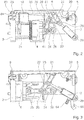
- the brewing module 1 has a brewing module housing 2. Two brewing module parts that can be moved relative to one another are guided in the brewing module housing 2, namely a diverting device 3 and an injector 4.
- the injector 4 has perforation elements for piercing a portion capsule 10 which is at least partially filled with an extraction material - for example ground coffee.
- the injector 4 is set up to introduce a liquid - for example hot water - through the perforation elements or past them into the pierced capsule, the water being able to be supplied via a water supply (not shown) which can have a flexible hose, for example.
- the diversion device 3 also has perforation elements, namely extraction-side piercing tips 39.
- perforation elements namely extraction-side piercing tips 39.
- These can, for example, be designed as in FIG WO 2015/039258 or in WO 2010/118544 described or have a different configuration; It is also possible to use principles other than piercing tips, for example with grid-like structures.
- the relative movement of the second brewing module part (injector) relative to the first brewing module part (diversion device) is achieved in the embodiment described here in that the diversion device 3 is mounted fixed to the housing, while the injector 4 can be moved along the horizontal axis.
- the brewing module As the brewing position located between the diverting device 3 and the injector 4 there is a capsule recognition position, into which the capsule passes after being inserted through a capsule insertion opening.
- the brewing module accordingly has a capsule recognition device 5 with a camera, the structure of which, for example, at least partially corresponds to that shown in FIG WO 2016/087190 corresponds to the structure described.
- the brewing module is set up in particular to hold the capsule inserted through the capsule insertion opening in the capsule recognition position before it goes down into the brewing position after successful capsule recognition and possibly after a further step (e.g. triggering of the brewing by the user).
- a mechanism can be present, for example, which comprises an element which engages under the capsule at the capsule recognition position and can be retracted in an electromechanically controlled manner for the transition to the brewing position.
- Other mechanisms for example purely mechanical, are also conceivable.
- the brewing module has an operating lever 6 which is mounted on a first fixed bearing point 20 and can be pivoted about it.
- the transmission mechanism from the operating lever 6 to the injector 4 is a lever mechanism and comprises a first toggle lever and a second toggle lever.
- the first toggle lever is formed by a first lever arm 21 engaging the operating lever and a second lever arm 22 which are pivotably connected to one another via a first toggle lever pin 23 so that a first knee joint is formed.
- the second toggle lever is formed by a third lever arm 24 and a fourth lever arm 25, which are pivotably connected to one another via a second toggle lever pin 26, so that a second knee joint is formed.
- the third lever arm 24 is mounted on a second fixed bearing point 28 and can be pivoted about this.
- the fourth lever arm 25 engages the injector 4 and is pivotable about a bearing pin 41 of the injector 4.
- the injector 4 is mounted in such a way that it can be positioned between the first brewing module part position (in Fig. 1 shown) and the second brewing module part position (in Fig. 3 visible) can be moved horizontally.
- the second lever arm 22 acts on the second knee joint, for example by engaging with the second toggle lever pin 26.
- a gas pressure spring 7 engages the first knee joint and extends between a third fixed bearing point 29, about which the gas pressure spring can be pivoted, and the first knee joint, whereby it is in engagement with the first toggle lever bolt 23, for example.
- a first locking mechanism is configured to prevent the second brewing module part from moving away from the first brewing module part position.
- the first locking mechanism has a locking bolt 81, for example magnetically triggered axially displaceable, which can be brought into engagement with the third and fourth lever arm in order to prevent the third and fourth lever arm from pivoting relative to one another in the blocked state, the third lever arm is connected to a fixed bearing point - a movement of the injector 4 is also completely prevented.
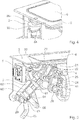
- a second locking mechanism is set up to block the operating lever 6 relative to the housing 2.
- the second locking mechanism works according to the known so-called ballpoint pen principle.
- a locking sleeve 83 which can be pressed down by the operating lever itself against a spring force and which is guided so that it is rotated by a predetermined angle - for example 90 ° - each time it is pressed down.
- the rotation can, for example, be brought about in a manner known per se by a control groove 84 of the locking sleeve, into which a control pin (not visible in the figures) engages.
- the locking sleeve blocks movement of the operating lever away from the second operating element position ( FIGS. 2 and 3 ) by means of locking wing 85 or releases it.
- the setup described enables the following operating sequence: In the open state, in which the operating lever 6 is pivoted upwards, is in the first operating element position ( Fig. 1 ), the capsule 10 can be inserted through the capsule insertion opening and thus reaches the capsule recognition position.
- the brewing module is also closed in the illustrated embodiment, which can also be connected, for example, to the fact that the capsule is shielded from ambient light at the capsule detection position.
- a corresponding sensor for example a switch, can determine that the operating lever is in the second operating lever position.
- Fig. 2 shows the brewing module during capsule recognition.
- the capsule detection can include, for example, that the capsule 10 is illuminated - a light beam 55 is in Fig. 2 indicated - and the illuminated capsule is detected by the camera, whereupon a code on the capsule or a color or similar is evaluated.
- the blocking is released again by the second locking mechanism in that the user pushes the operating lever slightly downwards, whereupon the user can pull the operating lever upwards. Due to the stiffness of the gas spring, this movement also bends the second toggle lever and moves it into the in Fig. 1 Brought position shown, whereupon the first locking mechanism can lock the second knee lift. Opening it can also cause the used capsule to fall down into your capsule container.
- a corresponding mechanism is for example in WO 2015/048914 described.
- the user wants to remove the capsule after the capsule has been recognized, instead of bringing it into the brewing position and closing the brewing chamber - e.g. if the capsule recognition shows that the selected capsule is not suitable for the desired drink - the user can press the Lever down to unlock the second locking mechanism. The gas pressure spring then presses the Control lever up again and the user can remove the capsule from the capsule detection position.
- a blower device 60 - functionally corresponding to a bellows - is also connected to the lever mechanism.
- This here has a cylinder 61 and a piston 62 displaceable in the cylinder.
- the cylinder 61 is pivotably mounted on the third fixed bearing point 29, while the piston 62 is connected to the first toggle bolt via a connecting rod, so that the piston 62 in the cylinder is also moved when the gas pressure spring is tensioned or released.
- An active volume, which is increased or decreased by moving the piston 62 in the cylinder, is formed in the orientation shown below the piston 62, in FIG Fig. 5 left below the piston.
- Two air connections 63, 64 open into the active volume of the cylinder 61.
- a first air connection 63 is connected to an air intake hose 65 through which air can be drawn in.
- the hose leads, for example, to a location inside or outside a beverage preparation machine housing at which it is to be expected that particularly dry and / or particularly warm air is present.
- the air intake hose leads to a location next to the water heating means, where there is a slightly increased temperature due to the resulting waste heat and the air is therefore preheated.
- a connecting hose 66 is connected to a second air connection 64, which leads to an area of the capsule recognition device 5 which leads to the Capsule recognition position directly adjoins a lens or a window, which is arranged between the camera sensor (e.g. with a CCD or CMOS sensor array) and the capsule recognition position and prevents, for example, hot vapors from reaching the camera sensor from the brewing chamber.
- the camera sensor e.g. with a CCD or CMOS sensor array
- the first and the second air connection 62, 63 and / or the corresponding hoses 65, 66 connected to them are each provided with a valve means - for example a simple valve as it is used in principle to inflate balloons - which cause through the first air connection air can only be sucked in but not blown out and conversely only air can be blown out through the second air connection but not sucked in.
- a valve means - for example a simple valve as it is used in principle to inflate balloons - which cause through the first air connection air can only be sucked in but not blown out and conversely only air can be blown out through the second air connection but not sucked in.
- the blower device 60 is arranged parallel to the air pressure spring 7. As a result, when the air pressure spring 7 is tensioned by actuating the operating lever 6, the air present in the cylinder 61 is blown through the connecting hose in front of the lens or window, which removes any fogging or soiling and / or prevents fogging / soiling. When the gas pressure spring is released when the brewing chamber is closed, the piston is moved back again, whereby air is sucked in.
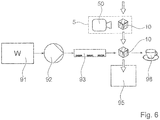
- FIG Figure 6 A machine according to the invention for preparing a brewed beverage from a portion capsule 10, namely here a coffee machine, with a brewing module is shown in FIG Figure 6 shown schematically.
- the brewing module has a water tank 91, a pump 92 for supplying brewing water to the injector 4 and a water heating device 93 (for example a continuous flow heater).
- the capsule recognition module 5 with camera 50 is in particular located above the brewing chamber. After the capsule recognition process, an inserted capsule can be transported downwards by the action of gravity, as described above.
- a capsule container 95 is also arranged below the brewing module, into which the capsules 1 fall or are transported after the brewing process.
- Numeral 98 denotes a coffee cup.
Description
Die Erfindung betrifft Extraktionsgeräte zum Zubereiten von Getränken oder dergleichen aus einem in einer Portionskapsel enthaltenen Extraktionsgut, beispielsweise gemahlenem Kaffee. Sie betrifft insbesondere ein Brühmodul für ein Extraktionsgerät, ein Kapselerkennungsmodul sowie eine Getränkezubereitungsmaschine mit einem solchen Brühmodul und/oder Kapselerkennungsmodul.The invention relates to extraction devices for preparing beverages or the like from an extraction material contained in a portion capsule, for example ground coffee. In particular, it relates to a brewing module for an extraction device, a capsule recognition module and a beverage preparation machine with such a brewing module and / or capsule recognition module.
Extraktionsgeräte zum Zubereiten von Getränken oder dergleichen aus einem in einer Portionsverpackung vorhandenen Extraktionsgut sind beispielsweise als Kaffee- oder Espressomaschinen bekannt. In vielen entsprechenden Systemen sind die Portionsverpackungen als Kapseln ausgebildet, in denen das Extraktionsgut bspw. luftdicht abgeschlossen ist. Für die Extraktion wird die Kapsel angestochen, beispielsweise an zwei einander gegenüberliegenden Seiten. Auf der ersten Seite wird dann eine Extraktionsflüssigkeit - im Allgemeinen heisses Wasser - eingeleitet. Auf der zweiten Seite wird das Extraktionsprodukt aus der Kapsel ausgeleitet. Dies geschieht in einem sogenannten Brühmodul. Ein solches weist eine Brühkammer auf, in der die Kapsel aufgenommen wird. Besonders beliebt sind Brühmodule, bei welchen die Kapsel eingeworfen und die Brühkammer manuell mittels eines Bedienhebels oder automatisch motorisiert verschlossen wird, wobei beim erneuten Öffnen der Brühkammer nach dem Brühvorgang die Kapsel selbsttätig aus der Brühkammer entfernt und in einen Kapselbehälter ausgeworfen wird. Solche Brühmodule mit selbsttätigem Kapselauswurf sind im Allgemeinen als horizontale Brühmodule ausgebildet, d.h. der Kapseleinwurf erfolgt von oben, das Verschliessen der Brühkammer ist eine horizontale Relativbewegung zweier Brühmodulteile, die Brühflüssigkeit fliesst im wesentlichen horizontal, und der Kapselbehälter ist unterhalb der Brühkammer ausgebildet.Extraction devices for preparing beverages or the like from an extraction material present in portion packaging are known, for example, as coffee or espresso machines. In many corresponding systems, the portion packs are designed as capsules in which the extraction material is sealed, for example, in an airtight manner. For the extraction, the capsule is pierced, for example on two opposite sides. An extraction liquid - generally hot water - is then introduced on the first side. On the second side, the extraction product is discharged from the capsule. This takes place in a so-called brewing module. One such has a brewing chamber in which the capsule is received. Brewing modules are particularly popular in which the capsule is thrown in and the brewing chamber is closed manually by means of an operating lever or automatically motorized, whereby when the brewing chamber is opened again after the brewing process, the capsule is automatically removed from the brewing chamber and ejected into a capsule container. Such brewing modules with automatic capsule ejection are generally horizontal Formed brewing modules, ie the capsule is inserted from above, the closure of the brewing chamber is a horizontal relative movement of two brewing module parts, the brewing liquid flows essentially horizontally, and the capsule container is formed below the brewing chamber.
Ein Problemfeld in diesem Zusammenhang betrifft das Erfassen von Kapseleigenschaften, beispielsweise das Auslesen von auf der Kapsel angebrachten Informationen zum Auslösen eines Brühprozesses abhängig von diesen Informationen. Eine Möglichkeit dafür besteht darin, die Kapsel mit einer geeigneten Markierung oder Farbkombination zu versehen und diese optisch zu erfassen. Dies geschieht beispielsweise mit einer Kamera. Weil die Brühkammer selbst im Betrieb zu heiss und verschmutzungsanfällig ist, geschieht das Erfassen der Informationen im Allgemeinen vor dem Brühprozess, während sich die Kapsel noch ausserhalb der Brühkammer befindet, an einer Kapselerkennungsposition.One problem area in this context relates to the detection of capsule properties, for example the reading out of information provided on the capsule in order to trigger a brewing process as a function of this information. One possibility for this is to provide the capsule with a suitable marking or color combination and to detect it optically. This is done, for example, with a camera. Because the brewing chamber itself is too hot and prone to contamination during operation, the information is generally recorded before the brewing process, while the capsule is still outside the brewing chamber, at a capsule detection position.
Beispielsweise aus
Es ist Aufgabe der Erfindung, eine Getränkezubereitungsmaschine und ein Brühmodul für eine solche zur Verfügung zu stellen, welche Nachteile des Standes der Technik überwinden, und welche durch eine möglichst einfache Konstruktion die Erfassung von Eigenschaften einer verwendeten Portionskapsel vor dem Brühprozess ermöglichen. Die verwendete Konstruktion sollte auch für die Implementierung als manuell zu betätigendes Brühmodul geeignet sein.The object of the invention is to provide a beverage preparation machine and a brewing module for such a machine which overcome the disadvantages of the prior art and which, through the simplest possible construction, enable the properties of a portion capsule used to be recorded prior to the brewing process. The construction used should also be suitable for implementation as a manually operated brewing module.
Gemäss der Erfindung wird ein Brühmodul zum Zubereiten eines Brühgetränks aus einer Portionskapsel zur Verfügung gestellt, welches aufweist:
- ein erstes Brühmodulteil und ein relativ zu diesem zwischen einer ersten Brühmodulteil-Position und einer zweiten Brühmodulteil-Position bewegbares zweites Brühmodulteil, wobei in der zweiten Brühmodulteil-Position durch das erste und zweite Brühmodulteil eine Brühkammer gebildet wird, welche die sich in einer Brühposition befindende Portionskapsel beim Brühvorgang mindestens teilweise umgibt, wobei das Brühmodul eingerichtet ist, durch das Einleiten einer Brühflüssigkeit in die Kapsel ein Brühgetränk zu brühen und dieses aus der Kapsel abzuleiten; und
- ein Bedienelement welches manuell von einer ersten in eine zweite Bedienelement-Position bringbar ist,
- a first brewing module part and a second brewing module part movable relative to this between a first brewing module part position and a second brewing module part position, wherein in the second brewing module part position a brewing chamber is formed by the first and second brewing module parts, which the portion capsule is in a brewing position surrounds at least partially during the brewing process, the brewing module being set up to brew a brewed beverage by introducing a brewing liquid into the capsule and to divert it from the capsule; and
- an operating element which can be moved manually from a first to a second operating element position,
Das Brühmodul zeichnet sich durch einen Energiespeicher aus, der eingerichtet ist, durch Bewegen des Bedienelements von der ersten in die zweite Position in das Brühmodul eingekoppelte Energie zwischenzuspeichern und durch eine Freigabe ausgelöst in eine Bewegung von der ersten Brühmodulteil-Position in die zweite Brühmodulteil-Position wieder umzusetzen.The brewing module is characterized by an energy store which is set up to temporarily store energy coupled into the brewing module by moving the operating element from the first to the second position and triggered by a release in a movement from the first brewing module part position to the second brewing module part position to implement again.
Das zweite Brühmodulteil ist beispielsweise relativ zum ersten Brühmodulteil bewegbar, indem das erste Brühmodulteil gehäusefest montiert ist und das zweite Brühmodulteil relativ zum Gehäuse, insbesondere linear-translatorisch, insbesondere horizontal bewegt wird. Auch eine Bewegung beider Brühmodulteile relativ zum Gehäuse oder eine Bewegung bloss des ersten Brühmodulteils relativ zum Gehäuse ist jedoch nicht ausgeschlossen.The second brewing module part can be moved relative to the first brewing module part, for example, in that the first brewing module part is mounted fixed to the housing and the second Brewing module part is moved relative to the housing, in particular linear-translationally, in particular horizontally. However, a movement of both brewing module parts relative to the housing or a movement only of the first brewing module part relative to the housing is not excluded.
Das zweite Brühmodulteil kann ein Injektor sein, durch welchen die Portionskapsel angestochen wird und von welchem beispielsweise heisses Wasser als Brühflüssigkeit in die Portionskapsel eingeleitet wird. Das erste Brühmodulteil kann eine Ausleitvorrichtung zum Ausleiten des Extraktionsprodukts aus der Kapsel bilden. Zu diesem Zweck weist es beispielsweise extraktionsseitige Anstechelemente zum extraktionsseitigen Anstechen der Kapsel oder andere Strukturen auf, welche die Kapsel extraktionsseitig öffnen.The second brewing module part can be an injector through which the portion capsule is pierced and from which, for example, hot water is introduced as brewing liquid into the portion capsule. The first brewing module part can form a discharge device for discharging the extraction product from the capsule. For this purpose it has, for example, extraction-side piercing elements for piercing the capsule on the extraction-side or other structures which open the capsule on the extraction-side.
Das Bedienelement kann insbesondere ein Bedienhebel sein, welcher durch eine Kippbewegung von oben nach unten von der ersten in die zweite Position gebracht werden kann. In der zweiten Position verschliesst beispielsweise der Bedienhebel eine Kapseleinlegeöffnung, welche durch ein Gehäuse der Getränkezubereitungsmaschine - beispielsweise der Brühmoduls - gebildet wird.The operating element can in particular be an operating lever which can be brought from the first to the second position by a tilting movement from top to bottom. In the second position, for example, the operating lever closes a capsule insertion opening which is formed by a housing of the beverage preparation machine - for example the brewing module.
Die Bewegung des Bedienelements von der ersten in die zweite Position erfolgt gegen einen mechanischen Widerstand, sodass der Benutzer mechanische Arbeit leistet, wobei die dadurch in das Brühmodul eingekoppelte Energie (abzüglich der unvermeidlichen Verluste) im Energiespeicher zwischengespeichert wird. Dieser gibt nach der Freigabe diese Energie in wieder ab, indem er die zum Schliessen der Brühkammer (zum Bewegen des zweiten Brühmodulteils relativ zum ersten Brühmodulteil in die zweite Brühmodul-Position) notwendige mechanische Arbeit leistet.The movement of the operating element from the first to the second position takes place against a mechanical resistance, so that the user performs mechanical work, whereby the energy coupled into the brewing module (minus the unavoidable losses) is temporarily stored in the energy store. After the release, the latter emits this energy again by performing the mechanical work necessary to close the brewing chamber (to move the second brewing module part relative to the first brewing module part into the second brewing module position).
Es kann optional vorgesehen sein, dass die im Energiespeicher gespeicherte Energie zum Zurückbewegen des Bedienelements in die erste Position verwendet werden kann, wenn keine Freigabe erfolgt, bspw. wenn die Kapselerkennung nicht erfolgreich war oder die Getränkezubereitungsmaschine eine Störung meldet.It can optionally be provided that the energy stored in the energy store can be used to move the operating element back into the first position if there is no release, for example if the capsule recognition was unsuccessful or the beverage preparation machine reports a malfunction.
Der Energiespeicher kann insbesondere eine Feder sein, wobei dann das Bewegen des Bedienelements in die zweite Position entgegen der Kraft der Feder erfolgt und die Feder dadurch gespannt wird. Nach der Freigabe wird die Feder dadurch entspannt, dass das zweite Brühmodulteil relativ zum ersten Brühmodulteil bewegt wird.The energy store can in particular be a spring, the operating element then being moved into the second position against the force of the spring and the spring being tensioned as a result. After the release, the spring is relaxed in that the second brewing module part is moved relative to the first brewing module part.
Weiter kann ein Dämpfungsmechanismus vorhanden sein, welcher verhindert, dass das zweite Brühmodulteile - bzw. das Bedienelement - bei der entsprechenden durch die Feder verursachten Bewegung zu sehr beschleunigt wird und dadurch gegen einen Anschlag schnellt. Ein solcher Dämpfungsmechanismus kann im Energiespeicher selbst oder separat davon ausgebildet sein.Furthermore, there can be a damping mechanism which prevents the second brewing module part - or the operating element - from being accelerated too much during the corresponding movement caused by the spring and thus from snapping against a stop. Such a damping mechanism can be formed in the energy store itself or separately therefrom.
In einem Beispiel ist der Energiespeicher eine Gasdruckfeder. Eine solche hat den Vorteil, dass ein Dämpfungsmechanismus gleich in die Feder integriert werden kann.In one example, the energy store is a gas pressure spring. This has the advantage that a damping mechanism can be integrated into the spring.
Zum Bewegen des zweiten Brühmodulteils in die zweite Brühmodulteil-Position übt der Energiespeicher beispielsweise direkt oder indirekt eine Kraft auf das zweite Brühmodulteil in Richtung der zweiten Brühmodulteil-Position und auf das Bedienelement in Richtung erste Position aus: Wenn der Energiespeicher gefüllt und das zweite Brühmodulteil nicht blockiert ist, schliesst sich die Brühkammer, wenn der Energiespeicher gefüllt und das Bedienelement nicht blockiert ist, bewegt sich das Bedienelement zurück in Richtung erste Position. Letzteres kann wie erwähnt benutzt werden, wenn ein Zubereitungsvorgang abgebrochen werden soll, d.h. wenn die Kapseleinlegeöffnung wieder zugänglich sein soll, damit die Kapsel entnommen werden kann.To move the second brewing module part into the second brewing module part position, the energy store exerts, for example, directly or indirectly a force on the second brewing module part in the direction of the second brewing module part position and on the operating element in the direction of the first position: When the energy store is full and the second brewing module part is not is blocked, the brewing chamber closes, when the energy store is full and the operating element is not blocked, the operating element moves back towards the first position. The latter can as mentioned can be used when a preparation process is to be interrupted, ie when the capsule insertion opening is to be accessible again so that the capsule can be removed.
Das Brühmodul kann insbesondere einen Übertragungsmechanismus zum Einkoppeln der am Bedienelement geleisteten Arbeit in den Energiespeicher und zum Umsetzen der arbeitsleistenden Kraft vom Energiespeicher in eine Bewegung des zweiten Brühmodulteils relativ zum ersten Brüllmodulteil aufweisen.The brewing module can in particular have a transmission mechanism for coupling the work performed on the operating element into the energy store and for converting the work-performing force from the energy store into a movement of the second brewing module part relative to the first roaring module part.
Ein solcher Übertragungsmechanismus - er kann auch als eine Art Getriebe aufgefasst werden - kann beispielsweise als Hebelmechanismus ausgebildet sein. Ergänzend oder alternativ kann er auch andere mechanische Kraft- bzw. Drehmomentübertragungsmittel beinhalten, beispielsweise ineinander greifende Zahnräder, einen Schneckenantrieb, etc.Such a transmission mechanism - it can also be understood as a type of gear - can be designed as a lever mechanism, for example. In addition or as an alternative, it can also contain other mechanical force or torque transmission means, for example meshing gears, a worm drive, etc.
Der Übertragungsmechanismus kann insbesondere mehrere Kopplungsstellen aufweisen. Beispielsweise kann Folgendes vorgesehen sein:
- An einer ersten Kopplungsstelle greift das Bedienelement an, und die am Bedienelement durch Bewegen in die zweite Position angesetzte Kraft wird durch den Übertragungsmechanismus an den Energiespeicher übertragen und spannt dort ggf. dessen Feder. Bei diesem Vorgang bewegt sich bspw. das zweite Brühmodulteil nicht.
- An einer zweiten Kopplungsstelle ist der Übertragungsmechanismus an den Energiespeicher gekoppelt.
- An einer dritten Kopplungsstelle ist der Übertragungsmechanismus an das zweite Brühmodulteil bzw. einen Bewegungsmechanismus zur Bewegung des zweiten Brühmodulteils relativ zum ersten Brühmodulteil (das kann auch eine Bewegung beider Brühmodulteile relativ zum Gehäuse beinhalten) gekoppelt.
- The operating element engages at a first coupling point, and the force applied to the operating element by moving it into the second position is transmitted to the energy store by the transmission mechanism and tensions its spring there, if necessary. During this process, for example, the second brewing module part does not move.
- The transmission mechanism is coupled to the energy store at a second coupling point.
- At a third coupling point, the transmission mechanism is coupled to the second brewing module part or a movement mechanism for moving the second brewing module part relative to the first brewing module part (this can also include a movement of both brewing module parts relative to the housing).
Eine Bewegung des Übertragungsmechanismus an der ersten und an der dritten Kopplungsstelle kann bspw. gezielt blockier- und freigebbar sein. Dadurch sind verschiedene Zustände möglich:
- In einem ersten Zustand ist die dritte Kopplungsstelle blockiert, was bedeutet, dass das zweite Brühmodulteil direkt oder indirekt blockiert ist, und die erste Kopplungsstelle ist freigegeben. In diesem Zustand sind das Bedienelement und der Energiespeicher aneinander gekoppelt - durch eine Bewegung des Bedienelements kann Energie in den Energiespeicher eingekoppelt werden (ggf. durch Spannen der Feder). Umgekehrt kann der Energiespeicher das Bedienelement von der zweiten Position zurück in Richtung der ersten Position bewegen, wenn keine Gegenkraft angesetzt wird.
- In einem zweiten Zustand sind sowohl die erste als auch die dritte Kopplungsstelle blockiert. In diesem Zustand ist keine Bewegung des Übertragungsmechanismus möglich. Im Energiespeicher vorhandene Energie bleibt dort gespeichert. Dieser zweite Zustand wird bspw. nach der Bedienung des Bedienelements eingenommen, während eine Kapselerkennung stattfindet und bevor das Brühmodul geschlossen wird.
- In einem dritten Zustand ist die erste Kopplungsstelle blockiert, bspw. indem das Bedienelement blockiert ist, und die dritte Kopplungsstelle ist freigegeben. In diesem Zustand bewegt der Energiespeicher das zweite Brühmodulteil relativ zum ersten, gegebenenfalls indem die vorher gespannte Feder die Federkraft über den Übertragungsmechanismus auf den entsprechenden Bewegungsmechanismus überträgt.
- In einem vierten Zustand sind sowohl die erste als auch die dritte Kopplungsstelle freigegeben. Indem ein Laden des Energiespeichers (ggf. Spannen der Feder) einen grösseren mechanischen Widerstand bietet als ein Bewegen der Brühmodulteile relativ zueinander, sind in diesem vierten Zustand das Bedienelement und der Bewegungsmechanismus der Brühmodulteile faktisch aneinander gekoppelt, d.h. im vierten Zustand kann bei leerem - oder blockiertem - Energiespeicher das Bedienelement direkt das zweite Brühmodulteil relativ zum ersten Brühmodulteil bewegen, wie das in Getränkezubereitungsmaschinen nach dem Stand der Technik immer der Fall ist. Der vierte Zustand wird eingenommen, wenn nach erfolgter Brühung die Brühkammer wieder geöffnet werden soll. Die Öffnung der Brühkammer wird dann durch ein Zurückbewegen des Bedienelements an die erste Position bewirkt, woraufhin erneut eine Kapsel eingelegt werden. Nach Einnahme des ersten Zustands kann erneut Energie in den Energiespeicher gekoppelt werden.
- In a first state, the third coupling point is blocked, which means that the second brewing module part is blocked directly or indirectly, and the first coupling point is released. In this state, the control element and the energy store are coupled to one another - energy can be coupled into the energy store by moving the control element (possibly by tensioning the spring). Conversely, the energy store can move the operating element from the second position back in the direction of the first position if no counterforce is applied.
- In a second state, both the first and the third coupling point are blocked. In this state, no movement of the transmission mechanism is possible. The energy present in the energy storage device remains stored there. This second state is assumed, for example, after the operating element has been operated, while capsule detection takes place and before the brewing module is closed.
- In a third state, the first coupling point is blocked, for example in that the operating element is blocked, and the third coupling point is released. In this state, the energy store moves the second brewing module part relative to the first, possibly in that the previously tensioned spring transfers the spring force via the transmission mechanism to the corresponding movement mechanism.
- In a fourth state, both the first and the third coupling point are released. Since charging the energy store (possibly tensioning the spring) offers greater mechanical resistance than moving the brewing module parts relative to one another, in this fourth state the control element and the movement mechanism of the brewing module parts are effectively coupled to one another, i.e. in the fourth state, when the - or blocked - energy storage move the operating element directly the second brewing module part relative to the first brewing module part, as is always the case in beverage preparation machines according to the prior art. The fourth state is assumed when the brewing chamber is to be opened again after brewing has taken place. The brewing chamber is then opened by moving the operating element back to the first position, whereupon a capsule is inserted again. After taking the first state, energy can again be coupled into the energy store.
Im Prinzip wäre es auch möglich, auch die zweite Kopplungsstelle bzw. den Energiespeicher blockierbar auszugestalten. Sofern die erwähnte Bedingung erfüllt ist, wonach ein Laden des Energiespeichers - gegebenenfalls abhängig von der Ausgestaltung des Übertragungsmechanismus über entsprechende Über- oder Untersetzungen - mehr Kraft benötigt als ein Bewegen des zweiten Brühmodulteils relativ zum ersten Brühmodulteil, ist das aber nicht notwendig, da die vier erwähnten Zustände ausreichen.In principle, it would also be possible to configure the second coupling point or the energy store to be blockable. Provided that the mentioned condition is met, according to which charging the energy store - possibly depending on the design of the transmission mechanism via corresponding step-up or step-down steps - requires more force than moving the second brewing module part relative to the first brewing module part, this is not necessary, as the four states mentioned are sufficient.
Wenn der Übertragungsmechanismus als Hebelmechanismus ausgebildet ist, kann er nebst den drei Kopplungsstellen mindestens eine fixe Lagerstelle beinhalten.If the transmission mechanism is designed as a lever mechanism, it can contain at least one fixed bearing point in addition to the three coupling points.
In Ausführungsformen weist der Übertragungsmechanismus insbesondere einen ersten Kniehebel auf, wobei der Energiespeicher (bspw. die Feder) mit dem Kniegelenk des ersten Kniehebels verbunden ist. Da sich bei einem solchen Mechanismus die Kraftübersetzung abhängig vom Zustand ändert, kann er insbesondere so eingerichtet sein, dass die vom Energiespeicher eingekoppelte Kraft auch am Ende des Wegs ausreicht, wenn die Feder schon fast entspannt ist. Ein anderer Drehpunkt (End-Drehpunkt) des Kniehebels ist insbesondere mit dem Betätigungselement verbunden.In embodiments, the transmission mechanism has, in particular, a first toggle lever, the energy store (for example the spring) being connected to the knee joint of the first toggle lever. Since the force transmission changes depending on the state in such a mechanism, it can in particular be set up in such a way that the force coupled in by the energy store is also sufficient at the end of the path when the spring is almost relaxed. Another pivot point (end pivot point) of the toggle lever is in particular connected to the actuating element.
Wenn der Energiespeicher eine Feder ist, bspw. eine Druckluftfeder, kann er ggf. zwischen dem Kniegelenk des ersten Kniehebels und einer festen Drehachse (Lagerstelle) gelagert sein.If the energy store is a spring, for example a compressed air spring, it can optionally be mounted between the knee joint of the first toggle lever and a fixed axis of rotation (bearing point).
Ergänzend oder alternativ zum ersten Kniehebel weist der Übertragungsmechanismus in Ausführungsformen einen zweiten Kniehebel auf, der an einem der End-Drehpunkte mit dem zweiten Brühmodulteil und am anderen der End-Drehpunkte mit einer fixen Lagestelle verbunden ist. Über das Kniegelenk des zweiten Kniehebels wird die Antriebskraft eingekoppelt. Dadurch kann sichergestellt werden, dass die auf das zweite Brühmodulteil ausgeübte Kraft am Ende des Verschliesswegs, zur zweiten Brühmodulteil-Position hin besonders stark übersetzt wird, so dass die Brühmodulteile mit grosser Kraft dichtend gegeneinander gedrückt werden können.In addition to or as an alternative to the first toggle lever, the transmission mechanism in embodiments has a second toggle lever which is connected to the second brewing module part at one of the end pivot points and to a fixed location at the other of the end pivot points. The drive force is coupled in via the knee joint of the second toggle lever. In this way it can be ensured that the force exerted on the second brewing module part at the end of the closure path is translated particularly strongly towards the second brewing module part position so that the brewing module parts can be pressed against one another in a sealing manner with great force.
Der zweite End-Drehpunkt des ersten Kniehebels kann gegebenenfalls an das Kniegelenk des zweiten Kniehebels angeschlossen sein.The second end pivot point of the first toggle lever can optionally be connected to the knee joint of the second toggle lever.
Wenn das Bedienelement ein Bedienhebel ist, kann dieser auf der einen Seite an einem festen Drehpunkt gelagert sein, wobei die Kopplung zum Übertragungsmechanismus im Allgemeinen vom äusseren Ende des Bedienhebels entfernt angeordnet ist, um eine Übersetzung der vom Benutzer ausgeübten Kraft zu ermöglichen.If the operating element is an operating lever, this can be mounted on one side at a fixed pivot point, the coupling to the transmission mechanism generally being arranged away from the outer end of the operating lever in order to enable the force exerted by the user to be translated.
Das Brühmodul weist nebst den diskutierten Elementen beispielsweise eine Kapselerkennungsvorrichtung auf. Im Kontext des vorliegenden Lehre wird die Kapselerkennungsvorrichtung dem Brühmodul zugeordnet, da sie zu demjenigen Teil der Getränkezubereitungsmaschine gehört, welches die Kapsel aufnimmt und mit ihr wechselwirkt, welcher Teil in diesem Text eben Brühmodul genannt wird. Ein Brühmodul im Sinne des vorliegenden Texts kann, muss aber nicht als separates, eigenständiges und auswechselbares Modul vorhanden sein. Es kann sich auch aus verschiedenen, in die Getränkezubereitungsmaschine integrierten Komponenten zusammengesetzt sein.In addition to the elements discussed, the brewing module has, for example, a capsule recognition device. In the context of the present teaching, the capsule recognition device is assigned to the brewing module, since it belongs to that part of the beverage preparation machine that receives the capsule and interacts with it, which part is called the brewing module in this text. A brewing module within the meaning of the present text can, but does not have to, be available as a separate, independent and exchangeable module. It can also be composed of various components integrated into the beverage preparation machine.
Mit einer Kapselerkennungsvorrichtung kann - das ist an sich bekannt - insbesondere erstens bestimmt werden, ob die eingelegte Kapsel überhaupt für eine Verwendung in der Getränkezubereitungsmaschine geeignet ist oder nicht. Zweitens besteht die Möglichkeit, aufgrund erkannter Kapseleigenschaften an den Benutzer entsprechende Informationen auszugeben, bspw. über ein Display. Es kann beispielsweise der Getränketyp (Kaffee, Tee, etc.), die Sorte (z.B. "100% Arabica"), die empfohlene Zubereitungsart (z.B. "Espresso", "Ristretto" oder "Lungo" etc.) und/oder eine andere Information angezeigt werden. Drittens kann auch das von der Kaffeemaschine für die Brühung verwendete Programm aufgrund der erkannten Kapselsorte gewählt werden, bspw. können der Brühdruck, die Brühdauer sowie eventuell auch die Temperatur und/oder andere Eigenschaften abhängig davon eingestellt werden, ob die eingelegte Kapsel für die Zubereitung von z.B. Ristretto, Espresso oder Lungo vorgesehen ist.With a capsule recognition device - this is known per se - it can in particular firstly be determined whether the inserted capsule is at all suitable for use in the beverage preparation machine or not. Secondly, there is the possibility of outputting corresponding information to the user based on recognized capsule properties, for example via a display. It can For example, the type of drink (coffee, tea, etc.), the type (eg "100% Arabica"), the recommended preparation method (eg "Espresso", "Ristretto" or "Lungo" etc.) and / or other information can be displayed . Thirdly, the program used by the coffee machine for brewing can also be selected on the basis of the recognized capsule type, for example the brewing pressure, the brewing duration and possibly also the temperature and / or other properties can be set depending on whether the inserted capsule is used for the preparation of e.g. ristretto, espresso or lungo is provided.
Die Kapselerkennungsvorrichtung kann insbesondere eingerichtet sein, eine optische Kapselerkennung vorzunehmen, d.h. optische Merkmale der Portionskapsel über einen optischen Sensor auszulesen. Dazu kann auch ein Beleuchtungsmittel vorhanden sein, welches die Kapsel kontrolliert beleuchtet.The capsule recognition device can in particular be set up to carry out an optical capsule recognition, i.e. to read out optical features of the portion capsule via an optical sensor. For this purpose, a lighting means can also be present which illuminates the capsule in a controlled manner.
Geeignete optisch auslesbare Merkmale sind beispielsweise ein Strichcode, ein 2D-MatrixCode (bspw. QR-Code oder Aztec-Code), ein Piktogramm (Icon) und/oder auch eine bestimmte Farbgebung. Auch ein Code gemäss
Die Kapselerkennungsvorrichtung kann insbesondere angeordnet sein, die Kapselerkennung vorzunehmen, wenn die Kapsel an einer Kapselerkennungsposition ist, welche von der Brühposition verschieden ist und bspw. oberhalb dieser ist.The capsule recognition device can in particular be arranged to carry out the capsule recognition when the capsule is in a capsule recognition position which is different from the brewing position and, for example, is above it.
In Ausführungsformen kann insbesondere vorgesehen sein, dass die Kapselerkennung durch das Bewegen des Bedienelements in seine zweite Position ausgelöst wird.In embodiments it can be provided in particular that the capsule recognition is triggered by moving the operating element into its second position.
Ergänzend oder alternativ kann die Getränkezubereitungsmaschine eingerichtet sein, die erfolgte Kapselerkennung für die Freigabe der Bewegung des zweiten Brühmodulteils relativ zum ersten Brühmodulteil in die zweite Brühmodulteil-Position vorauszusetzen. Gegebenenfalls kann eine Eingabe durch den Benutzer als weitere Voraussetzung verlangt werden.In addition or as an alternative, the beverage preparation machine can be set up to assume that the capsule has been recognized for the release of the movement of the second brewing module part relative to the first brewing module part into the second brewing module part position. If necessary, an input by the user can be requested as a further requirement.
Vor oder während der Bewegung des zweiten Brühmodulteils relativ zum ersten Brühmodulteil erfolgt in diesen Ausführungsformen ein Transport der Kapsel von der Kapselerkennungsposition in die Brühposition, bspw. indem sie nach unten fällt. Zu diesem Zweck kann bspw. vorgesehen sein, dass ein Haltemittel, welches die Kapsel an der Kapselerkennungsposition mindestens teilweise untergreift, zurückgezogen wird.Before or during the movement of the second brewing module part relative to the first brewing module part, in these embodiments the capsule is transported from the capsule recognition position into the brewing position, for example by falling down. For this purpose it can be provided, for example, that a holding means, which at least partially engages under the capsule at the capsule recognition position, is withdrawn.
Insbesondere in Ausführungsformen mit optischer Kapselerkennungsvorrichtung kann das Brühmodul ferner eine mechanisch angetriebene Blasvorrichtung aufweisen. Eine solche funktioniert in der Art eines Blasebalgs. Sie kann als klassischer Blasebalg mit flexibler Membran oder bspw. auch als Kolbensystem ausgestaltet sein. Eine Blasvorrichtung ist insbesondere an den Übertragungsmechanismus gekoppelt und wird durch diesen angetrieben, insbesondere im Rahmen von ohnehin durchgeführten Bewegungen - beispielsweise beim Laden des Energiespeichers oder beim Bewegen des zweiten Brühmodulteils relativ zum ersten Brühmodulteil.In particular in embodiments with an optical capsule recognition device, the brewing module can furthermore have a mechanically driven blowing device. This works in the manner of a bellows. It can be designed as a classic bellows with a flexible membrane or, for example, as a piston system. A blowing device is coupled in particular to the transmission mechanism and is driven by it, in particular in the context of movements that are already carried out - for example when charging the energy store or when moving the second brewing module part relative to the first brewing module part.
Eine solche Blasvorrichtung ist insbesondere eingerichtet, einen Luftstrom über dasjenige transparente Teil der Kapselerkennungsvorrichtung zu erzeugen, welches das lichtempfindliche Element des optischen Sensors (ein solcher kann insbesondere eine Kamera sein) von dem Bereich trennt, an welchem sich die Kapsel befindet und durch welches hindurch die Kapselerkennung stattfindet. Dieses transparente Teil ist im Allgemeinen ein Fenster mit oder ohne Linsenfunktion (in diesem Kontext wird auch eine Kameralinse als "Fenster" bezeichnet, wenn sie gleichzeitig den Bereich des lichtempfindlichen Elements vom Bereich der Kapsel trennt). Der Luftstrom wird kapselseitig über das Fenster geführt, um einem Beschlagen des Fensters entgegenzuwirken und auch um es zu reinigen.Such a blowing device is in particular set up to generate an air flow over that transparent part of the capsule recognition device which separates the light-sensitive element of the optical sensor (such a camera can in particular be a camera) from the area in which the capsule is located and through which the Capsule detection takes place. This transparent part is generally a window with or without a lens function (in this context a camera lens is also referred to as a "window" if it simultaneously separates the area of the light-sensitive element from the area of the capsule). The air flow is guided over the window on the capsule side in order to counteract fogging of the window and also to clean it.
Eingangsseitig kann die Blasvorrichtung mit einem Bereich der Getränkezubereitungsmaschine verbunden sein, in welchem sich besonders trockene und/oder besonders warme Luft befindet, insbesondere in einer Umgebung des Wassererhitzungsmittels.On the input side, the blowing device can be connected to an area of the beverage preparation machine in which there is particularly dry and / or particularly warm air, in particular in the vicinity of the water heating means.
Die Erfindung betrifft auch eine Getränkezubereitungsmaschine mit einem Brühmodul der diskutierten Art.The invention also relates to a beverage preparation machine with a brewing module of the type discussed.
Nachfolgend werden Ausführungsbeispiele der Erfindung anhand von Figuren beschrieben. In den Figuren bezeichnen gleiche Bezugszeichen gleiche oder analoge Elemente. Es zeigen:
- Fig. 1
- eine Seitenansicht eines Brühmoduls, wobei einige Teile, insbesondere Gehäuseteile ausgeblendet sind;
- Fig. 2
- eine Seitenansicht des Brühmoduls gemäss
Fig. 1 während der Kapselerkennung; - Fig. 3
- eine Seitenansicht des Brühmoduls gemäss
Fig. 1 und2 während des Brühprozesses; - Fig. 4
- ein Detail des Brühmoduls gemäss
Fig. 1-3 , welches den zweiten Verriegelungsmechanismus erkennen lässt, - Fig. 5
- eine Detailansicht des Brühmoduls gemäss
Fig. 1-4 , und - Fig. 6
- ein Schema einer erfindungsgemässen Kaffeemaschine.
- Fig. 1
- a side view of a brewing module, with some parts, in particular housing parts, are hidden;
- Fig. 2
- a side view of the brewing module according to
Fig. 1 during capsule recognition; - Fig. 3
- a side view of the brewing module according to
Fig. 1 and2 during the brewing process; - Fig. 4
- a detail of the brewing module according to
Fig. 1-3 , which reveals the second locking mechanism, - Fig. 5
- a detailed view of the brewing module according to
Fig. 1-4 , and - Fig. 6
- a scheme of a coffee machine according to the invention.
Das Brühmodul 1 gemäss
Der Injektor 4 weist Perforationselemente zum Anstechen einer Portionskapsel 10 auf, die mindestens teilweise mit einem Extraktionsgut - bspw. gemahlenem Kaffee - gefüllt ist. Der Injektor 4 ist eingerichtet, eine Flüssigkeit - bspw. heisses Wasser - durch die Perforationselemente oder an diesen vorbei in die angestochene Kapsel einzubringen wobei das Wasser über eine Wasserzuführung (nicht gezeigt) zuführbar ist, die bspw. einen flexiblen Schlauch aufweisen kann.The
Auch die Ausleitvorrichtung 3 weist im hier beschriebenen Ausführungsbeispiel Perforationselemente auf, nämlich extraktionsseitige Anstechspitzen 39. Diese können beispielsweise ausgebildet sein wie in
Ausserdem weist die Ausleitvorrichtung beidseits der Kapsel zur Injektorseite hin ragende Führungsmittel 31 auf, wie sie beispielsweise in
Für die Zubereitung eines Brühgetränks wird wie an sich bekannt eine Kapsel zwischen der Ausleitvorrichtung 3 und dem Injektor 4 platziert, und diese werden so aufeinander zubewegt, dass zwischen diesen eine die Kapsel umfassende Brühkammer gebildet wird. Das heisse Wasser wird durch den Injektor unter Druck der Kapsel zugeführt, und das Extraktionsprodukt fliesst durch die Ausleitvorrichtung 3 via einen Getränkeauslauf 13 in ein bspw. darunter platziertes Trinkgefäss ab.For the preparation of a brewed beverage, as is known per se, a capsule is placed between the
Die relative Bewegung des zweiten Brühmodulteils (Injektor) relativ zum ersten Brühmodulteil (Ausleitvorrichtung) wird im hier beschriebenen Ausführungsbeispiel dadurch erreicht, dass die Ausleitvorrichtung 3 gehäusefest montiert ist, während der Injektor 4 entlang der horizontalen Achse bewegbar ist.The relative movement of the second brewing module part (injector) relative to the first brewing module part (diversion device) is achieved in the embodiment described here in that the
Über der zwischen den Ausleitvorrichtung 3 und Injektor 4 liegenden Brühposition befindet sich eine Kapselerkennungsposition, in welche die Kapsel nach Einlegen durch eine Kapseleinlegeöffnung gelangt. Nebst der der Brühkammereinheit mit Ausleitvorrichtung 3 und Injektor 4 weist das Brühmodul dementsprechend eine Kapselerkennungsvorrichtung 5 mit Kamera auf, deren Aufbau beispielsweise mindestens teilweise dem in
Das Brühmodul ist insbesondere eingerichtet, die durch die Kapseleinlegeöffnung eingelegte Kapsel in der Kapselerkennungsposition zu halten bevor sie nach erfolgreicher Kapselerkennung und ggf. nach einem weiteren Schritt (bspw. Auslösen der Brühung durch den Benutzer) nach unten in die Brühposition gelangt. Zu diesem Zweck kann ein bspw. Mechanismus vorhanden sein, der ein die Kapsel an der Kapselerkennungsposition untergreifendes, für den Übergang in die Brühposition elektromechanisch gesteuert rückziehbares Element umfasst. Auch andere, bspw. rein mechanisch arbeitende Mechanismen sind denkbar.The brewing module is set up in particular to hold the capsule inserted through the capsule insertion opening in the capsule recognition position before it goes down into the brewing position after successful capsule recognition and possibly after a further step (e.g. triggering of the brewing by the user). For this purpose, a mechanism can be present, for example, which comprises an element which engages under the capsule at the capsule recognition position and can be retracted in an electromechanically controlled manner for the transition to the brewing position. Other mechanisms, for example purely mechanical, are also conceivable.
Für die Bedienung durch den Benutzer zwecks Schliessen der Brühkammer weist das Brühmodul einen Bedienhebel 6 auf, der an einer ersten fixen Lagerstelle 20 gelagert und um diese schwenkbar ist. Der Übertragungsmechanismus vom Bedienhebel 6 zum Injektor 4 ist ein Hebelmechanismus und umfasst einen ersten Kniehebel und einen zweiten Kniehebel. Der erste Kniehebel wird durch einen am Bedienhebel angreifenden ersten Hebelarm 21 und einen zweiten Hebelarm 22 gebildet die über einen ersten Kniehebelbolzen 23 schwenkbar miteinander verbunden sind, so dass sich ein erstes Kniegelenk bildet. Der zweite Kniehebel wird durch einen dritten Hebelarm 24 und einen vierten Hebelarm 25 gebildet, die über einen zweiten Kniehebelbolzen 26 schwenkbar miteinander verbunden sind, so dass ein zweites Kniegelenk gebildet wird. Der dritte Hebelarm 24 ist an einer zweiten fixen Lagerstelle 28 gelagert und um diese schwenkbar. Der vierte Hebelarm 25 greift am Injektor 4 an und ist um einen Lagerzapfen 41 des Injektors 4 schwenkbar. Der Injektor 4 ist so gelagert, dass er zwischen der ersten Brühmodulteil-Position (in
Der zweite Hebelarm 22 greift am zweiten Kniegelenk an, beispielsweise indem er mit dem zweiten Kniehebelbolzen 26 in Eingriff steht.The
Am ersten Kniegelenk greift eine Gasdruckfeder 7 an, die sich zwischen einer dritten fixen Lagerstelle 29, um welche die Gasdruckfeder schwenkbar ist, und dem ersten Kniegelenk erstreckt, wobei sie bspw. mit dem ersten Kniehebelbolzen 23 im Eingriff steht.A
Das Brühmodul weist ausserdem zwei Verriegelungsmechanismen auf.The brewing module also has two locking mechanisms.
Ein erster Verriegelungsmechanismus ist eingerichtet, eine Bewegung des zweiten Brühmodulteils von der ersten Brühmodulteilposition weg zu verhindern. Im dargestellten Ausführungsbeispiel weist der erste Verriegelungsmechanismus einen bspw. magnetisch ausgelöst in axialer Richtung verschiebbaren Verriegelungsbolzen 81 auf, welcher mit dem dritten und vierten Hebelarm in Eingriff bringbar ist, um im Blockierzustand ein Verschwenken des dritten und vierten Hebelarms relativ zueinander zu verhindern, was - da der dritte Hebelarm mit einer fixen Lagerstelle verbunden ist - auch eine Bewegung des Injektors 4 ganz verhindert. Alternativ wäre es auch möglich, einen Verriegelungsmechanismus vorzusehen, der direkt mit dem Injektor in Eingriff bringbar ist, oder der eingerichtet ist, eine Bewegung des dritten oder vierten Hebelarms relativ zum Gehäuse zu verhindern.A first locking mechanism is configured to prevent the second brewing module part from moving away from the first brewing module part position. In the illustrated embodiment, the first locking mechanism has a locking
Ein zweiter Verriegelungsmechanismus ist eingerichtet, den Bedienhebel 6 relativ zum Gehäuse 2 zu blockieren. In der dargestellten Ausführungsform funktioniert der zweite Verriegelungsmechanismus nach dem bekannten sogenannten Kugelschreiber-Prinzip. Dazu ist eine Verriegelungshülse 83 vorhanden, welche durch den Bedienhebel selbst entgegen einer Federkraft nach unten gedrückt werden kann, und welche so geführt ist, dass sie bei jedem Drücken nach unten um einen vorgegebenen Winkel - bspw. 90° - gedreht wird. Die Drehung kann bspw. in an sich bekannter Art durch eine Steuernut 84 der Verriegelungshülse bewirkt werden, in welche ein Steuerungszapfen (in den Figuren nicht sichtbar) eingreift. Je nach eingenommener Orientierung blockiert die Verriegelungshülse eine Bewegung des Bedienhebels weg von der zweiten Bedienelement-Position (
Die beschriebene Einrichtung ermöglicht folgenden Bedienablauf:
Im geöffneten Zustand, in welchem der Bedienhebel 6 nach oben verschwenkt, an der ersten Bedienelement-Position ist (
In the open state, in which the
Daraufhin betätigt der Benutzer den Bedienhebel 6 entgegen der Federkraft der Gasdruckfeder 7, während der erste Verriegelungsmechanismus das zweite Brühmodulteil blockiert. Der Bedienhebel gelangt von der ersten Bedienelement-Position in die zweite Bedienelement-Position. Dort wird der Bedienhebel durch den zweiten Verriegelungsmechanismus verriegelt.The user then operates the operating
Durch das Bringen des Bedienhebels in die zweite Bedienelement-Position wird im dargestellten Ausführungsbeispiel auch das Brühmodul verschlossen, womit bspw. auch verbunden sein kann, dass die Kapsel an der Kapselerkennungsposition von Umgebungslicht abgeschirmt wird.By bringing the operating lever into the second operating element position, the brewing module is also closed in the illustrated embodiment, which can also be connected, for example, to the fact that the capsule is shielded from ambient light at the capsule detection position.
Dann findet, bspw. selbsttätig, d.h. ohne weiteres Zutun durch den Benutzer (ein entsprechender Sensor, bspw. Schalter, kann feststellen, dass der Bedienhebel an der zweiten Bedienhebel-Position ist) die Kapselerkennung statt.
Ausgelöst durch die erfolgreiche Kapselerkennung oder durch eine Aktion des Benutzers wird anschliessend ein Bewegen der Kapsel nach unten bewirkt und die Brühkammer geschlossen. Dazu wird die Blockierung durch den ersten Verriegelungsmechanismus aufgehoben, bspw. durch einen Elektromagneten, welcher den Verriegelungsbolzen 81 axial verschiebt und so aus dem Eingriff mit dem dritten Hebelarm 24 löst. Aufgrund der durch die Gasdruckfeder ausgeübten Federkraft wird dadurch das erste Kniegelenk und als Folge auch das zweite Kniegelenk gestreckt, was den Injektor 4 bewegt und die Brühkammer schliesst, während sich die Kapsel darin befindet.Triggered by the successful capsule recognition or by an action by the user, the capsule is then moved downwards and the brewing chamber is closed. This is the blocking by the first The locking mechanism is canceled, for example by an electromagnet, which axially displaces the locking
Dann kann der Brühprozess in an sich bekannter Art erfolgen, indem heisses Wasser unter Druck in die beim Schliessen der Brühkammer angestochene Kapsel eingeleitet und das entstehende Brühgetränk aus über die Ausleitvorrichtung aus dieser abgeleitet wird.The brewing process can then take place in a manner known per se, in that hot water under pressure is introduced into the capsule pierced when the brewing chamber is closed and the resulting brewed beverage is diverted from the latter via the diversion device.
Nach erfolgter Brühung wird die Blockierung durch den zweiten Verriegelungsmechanismus wieder aufgehoben, indem der Benutzer den Bedienhebel leicht nach unten drückt, woraufhin der Benutzer den Bedienhebel nach oben ziehen kann. Aufgrund der Steifigkeit der Gasdruckfeder wird durch diese Bewegung auch der zweite Kniehebel gebeugt und in die in
Wenn der Benutzer nach erfolgter Kapselerkennung die Kapsel entnehmen möchte anstatt sie in die Brühposition zu bringen und die Brühkammer zu schliessen - bspw. wenn sich aufgrund der Kapselerkennung herausstellt, dass die gewählte Kapsel für das gewünschte Getränk nicht geeignet ist - kann der Benutzer durch Drücken des Bedienhebels nach unten die Blockierung durch den zweiten Verriegelungsmechanismus aufheben. Daraufhin drückt die Gasdruckfeder den Bedienhebel wieder nach oben, und der Benutzer kann die Kapsel aus der Kapselerkennungsposition entfernen.If the user wants to remove the capsule after the capsule has been recognized, instead of bringing it into the brewing position and closing the brewing chamber - e.g. if the capsule recognition shows that the selected capsule is not suitable for the desired drink - the user can press the Lever down to unlock the second locking mechanism. The gas pressure spring then presses the Control lever up again and the user can remove the capsule from the capsule detection position.
Ein weiteres Merkmal ist in
In das aktive Volumen des Zylinders 61 münden zwei Luftanschlüsse 63, 64.Two
Ein erster Luftanschluss 63 ist mit einem Luftansaugschlauch 65 verbunden, durch welchen Luft angesaugt werden kann. Der Schlauch führt bspw. zu einem Ort innerhalb oder ausserhalb eines Getränkezubereitungsmaschinengehäuses, an welchem damit zu rechnen ist, dass besonders trockene und/oder besonders warme Luft vorhanden ist. In einem Ausführungsbeispiel führt der Luftansaugschlauch zu einem Ort neben den Wassererhitzungsmitteln, wo aufgrund entstehender Abwärme eine leicht erhöhte Temperatur herrscht und die Luft daher vorgewärmt wird.A
An einen zweiten Luftanschluss 64 ist ein Verbindungsschlauch 66 angeschlossen, welcher zu einem Bereich der Kapselerkennungsvorrichtung 5 führt, der zur Kapselerkennungsposition hin unmittelbar an eine Linse oder ein Fenster angrenzt, welche bzw. welches zwischen dem Kamerasensor (bspw. mit einem CCD oder CMOS-Sensorarray) und der Kapselerkennungsposition angeordnet ist und bspw. verhindert, dass heisse Dämpfe aus der Brühkammer zum Kamerasensor gelangen.A connecting
Der erste und der zweite Luftanschluss 62, 63 und/oder die entsprechenden daran angeschlossenen Schläuche 65, 66 sind je mit einem Ventilmittel versehen - bspw. einen einfachen Ventil, wie es vom Prinzip her zum Aufblasen von Luftballons verwendet wird - welche bewirken, dass durch den ersten Luftanschluss Luft nur angesaugt, nicht aber ausgeblasen werden kann und durch den zweiten Luftanschluss umgekehrt nur Luft ausgeblasen, nicht aber angesaugt werden kann.The first and the
Die Blasvorrichtung 60 ist parallel zur Luftdruckfeder 7 angeordnet. Dadurch wird beim Spannen der Luftdruckfeder 7 durch Betätigen des Bedienhebels 6 die im Zylinder 61 vorhandene Luft durch den Verbindungsschlauch vor die Linse bzw. das Fenster geblasen, wodurch ein eventueller Beschlag oder eine Verschmutzung entfernt wird und/oder einem Beschlagen/verschmutzen vorgebeugt wird. Beim Entspannen der Gasdruckfeder beim Verschliessen der Brühkammer wird der Kolben wieder zurückbewegt, wodurch Luft angesaugt wird.The
Eine mechanisch angetriebene Blasvorrichtung der beschriebenen Art kann auch an einer anderen Stelle als der beschriebenen im Brühmodul angeordnet sein und durch Relativbewegungen von Elementen betätigt werden, bspw. parallel zum ersten Kniehebel oder eventuell zum zweiten Kniehebel oder zwischen dem Brühmodulgehäuse und dem Injektor. Besonders vorteilhaft ist eine Anordnung, die wie im beschriebenen Ausführungsbeispiel einen Luftstrom zur Kapselerkennungsvorrichtung unmittelbar vor der Kapselerkennung bewirkt.A mechanically driven blowing device of the type described can also be arranged in a different location than the one described in the brewing module and actuated by relative movements of elements, for example parallel to the first toggle lever or possibly to the second toggle lever or between the brewing module housing and the injector. An arrangement is particularly advantageous which, as in the exemplary embodiment described, causes an air flow to the capsule recognition device immediately before the capsule recognition.
In
Eine erfindungsgemässe Maschine zum Zubereiten eines Brühgetränks aus einer Portionskapsel 10, nämlich hier eine Kaffeemaschine, mit einem Brühmodul ist in
- 11
- BrühmodulBrewing module
- 22
- BrühmodulgehäuseBrew module housing
- 33
- AusleitvorrichtungReject device
- 44th
- InjektorInjector
- 55
- KapselerkennungsvorrichtungCapsule detection device
- 66th
- BedienhebelControl lever
- 77th
- GasdruckfederGas spring
- 1010
- PortionskapselPortion capsule
- 1313th
- GetränkeauslaufBeverage outlet
- 2020th
- erste fixe Lagerstellefirst fixed storage location
- 2121
- Erster HebelarmFirst lever arm
- 2222nd
- zweiter Hebelarmsecond lever arm
- 2323
- erster Kniehebelbolzenfirst toggle bolt
- 2424
- dritter Hebelarmthird lever arm
- 2525th
- vierter Hebelarmfourth lever arm
- 2626th
- zweiter Kniehebelbolzensecond toggle bolt
- 2828
- zweite fixe Lagerstellesecond fixed storage location
- 2929
- dritte fixe Lagerstellesthird fixed storage location
- 3131
- FührungsmittelGuide means
- 3939
- extraktionsseitige Anstechspitzenextraction-side piercing tips
- 4141
- LagerzapfenJournal
- 5050
- Kameracamera
- 5555
- LichtstrahlBeam of light
- 6060
- BlasvorrichtungBlower
- 6161
- Zylindercylinder
- 6262
- Kolbenpiston
- 6363
- erster Luftanschlussfirst air connection
- 6464
- zweiter Luftanschlusssecond air connection
- 6565
- LuftansaugschlauchAir intake hose
- 6666
- VerbindungsschlauchConnecting hose
- 8181
- VerriegelungsbolzenLocking bolt
- 8383
- VerriegelungshülseLocking sleeve
- 8484
- SteuernutControl groove
- 8585
- VerriegelungsflügelLocking wing
- 9191
- WassertankWater tank
- 9292
- Pumpepump
- 9393
- WasserheizungsvorrichtungWater heating device
- 9595
- KapselbehälterCapsule container
- 9898
- Kaffeetassecoffee pot
Claims (15)
- A brewing module for preparing a brewed drink from a portion capsule, comprising:• a first brewing module part (3) and a second brewing module part (4), the second brewing module part (4) being movable relative to said first brewing module part (3) between a first brewing module part position and a second brewing module part position, wherein, in the second brewing module part position, a brewing chamber is formed which during a brewing procedure at least partly surrounds the portion capsule (10) situated in a brewing position, wherein the brewing module is configured to brew a brewed drink by way of introducing a brewing fluid into the portion capsule and to discharge said brewed drink out of the portion capsule; and• an operating element (6) which can be brought manually from a first into a second operating element position,characterised by an energy store (7) which is configured to intermediately store energy which is coupled into the brewing module, by way of moving the operating element from the first into the second position, and to again convert it, activated by a release, into a movement from the first brewing module part position into the second brewing module part position.
- A brewing module according to claim 1, wherein the operating element (6) is an operating lever which can be brought from the first into the second position by way of a top down tilting movement and wherein the operating element in the second position closes a capsule insert opening.
- A brewing module according to claim 1 or 2, wherein the energy store (7) comprises a spring which is loaded by way of the moving of the operating element from the first into the second position.
- A brewing module according to one of the preceding claims, comprising a damping mechanism which acts in a damping manner on movement from the first brewing module part position into the second brewing module part position.
- A brewing module according to claim 4, wherein the energy store (7) is a gas compression spring, into which the damping mechanism is integrated.
- A brewing module according to one of the preceding claims, comprising a transmission mechanism for coupling the physical work executed on the operating element (6) into the energy store (7), and for converting a work-executing force from the energy store (7) into the movement of the second brewing module part (4) relative to the first brewing module part (3).
- A brewing module according to claim 6, wherein the transmission mechanism is designed as a lever mechanism and comprises a plurality of levers (21, 22, 24, 25) which are pivotable relative to one another.
- A brewing module according to claim 7, wherein the transmission mechanism comprises a first toggle lever, wherein the energy store is connected to a toggle joint (23) of the first toggle lever and an end rotation point of the toggle lever is connected to the actuation element.
- A brewing module according to claim 7 or 8, wherein the transmission mechanism comprises a second toggle lever which at one of the end rotation points is connected to the second brewing module part and at the other of the end rotation points to a fixed mounting location (28), wherein, via a toggle joint (26) of the second toggle lever, a drive force for the movement from the first brewing module part position into the second brewing module part position can be coupled in.
- A brewing module according to claim 6-9, comprising a mechanically drivable blowing device (60) which is arranged to be driven by the transmission mechanism.
- A brewing module according to one of the preceding claims, comprising a first locking mechanism which is configured to prevent or release a movement of the second brewing module part (4) away from the first brewing module part position, depending on its state.
- A brewing module according to one of the preceding claims, comprising a second locking mechanism which is configured to prevent or release a movement of the operating element away from the second operating element position, depending on its state.
- A brewing module according to one of the preceding claims, comprising a capsule recognition device (5) which is configured to electronically detect characteristics of a portion capsule which is located at a capsule recognition position.
- A brewing module according to claim 13, wherein the capsule recognition position is above the brewing position.
- A drinks preparation machine, in particular coffee machine, comprising a water feed, a pump (92) and a water heating means (93) as well as a brewing module according to one of the preceding claims.
Priority Applications (1)
| Application Number | Priority Date | Filing Date | Title |
|---|---|---|---|
| PL17818148T PL3558075T3 (en) | 2016-12-22 | 2017-12-20 | Brew module and machine for preparing beverages |
Applications Claiming Priority (2)
| Application Number | Priority Date | Filing Date | Title |
|---|---|---|---|
| EP16206245.9A EP3338600A1 (en) | 2016-12-22 | 2016-12-22 | Brew module and machine for preparing beverages |
| PCT/EP2017/083925 WO2018115184A1 (en) | 2016-12-22 | 2017-12-20 | Brewing module and beverage-preparing machine |
Publications (2)
| Publication Number | Publication Date |
|---|---|
| EP3558075A1 EP3558075A1 (en) | 2019-10-30 |
| EP3558075B1 true EP3558075B1 (en) | 2021-05-19 |
Family
ID=57588919
Family Applications (2)
| Application Number | Title | Priority Date | Filing Date |
|---|---|---|---|
| EP16206245.9A Withdrawn EP3338600A1 (en) | 2016-12-22 | 2016-12-22 | Brew module and machine for preparing beverages |
| EP17818148.3A Active EP3558075B1 (en) | 2016-12-22 | 2017-12-20 | Brew module and machine for preparing beverages |
Family Applications Before (1)
| Application Number | Title | Priority Date | Filing Date |
|---|---|---|---|
| EP16206245.9A Withdrawn EP3338600A1 (en) | 2016-12-22 | 2016-12-22 | Brew module and machine for preparing beverages |
Country Status (12)
| Country | Link |
|---|---|
| US (1) | US11337542B2 (en) |
| EP (2) | EP3338600A1 (en) |
| JP (1) | JP7102411B2 (en) |
| KR (1) | KR102444542B1 (en) |
| CN (1) | CN110113969B (en) |
| AU (1) | AU2017384674B2 (en) |
| CA (1) | CA3046722A1 (en) |
| HU (1) | HUE056184T2 (en) |
| PL (1) | PL3558075T3 (en) |
| PT (1) | PT3558075T (en) |
| RU (1) | RU2745347C2 (en) |
| WO (1) | WO2018115184A1 (en) |
Families Citing this family (9)
| Publication number | Priority date | Publication date | Assignee | Title |
|---|---|---|---|---|
| EP3403545A1 (en) * | 2017-05-19 | 2018-11-21 | Tchibo GmbH | Brewing module and machine for making beverages |
| US11647860B1 (en) | 2022-05-13 | 2023-05-16 | Sharkninja Operating Llc | Flavored beverage carbonation system |
| US11751585B1 (en) | 2022-05-13 | 2023-09-12 | Sharkninja Operating Llc | Flavored beverage carbonation system |
| US11634314B1 (en) | 2022-11-17 | 2023-04-25 | Sharkninja Operating Llc | Dosing accuracy |
| US11745996B1 (en) | 2022-11-17 | 2023-09-05 | Sharkninja Operating Llc | Ingredient containers for use with beverage dispensers |
| US11738988B1 (en) | 2022-11-17 | 2023-08-29 | Sharkninja Operating Llc | Ingredient container valve control |
| US11871867B1 (en) | 2023-03-22 | 2024-01-16 | Sharkninja Operating Llc | Additive container with bottom cover |
| US11925287B1 (en) | 2023-03-22 | 2024-03-12 | Sharkninja Operating Llc | Additive container with inlet tube |
| US11931704B1 (en) | 2023-06-16 | 2024-03-19 | Sharkninja Operating Llc | Carbonation chamber |
Citations (1)
| Publication number | Priority date | Publication date | Assignee | Title |
|---|---|---|---|---|
| WO2018026275A1 (en) * | 2016-08-03 | 2018-02-08 | Koninklijke Douwe Egberts B.V. | System, apparatus, method, capsule and kit of capsules for preparing a beverage |
Family Cites Families (31)
| Publication number | Priority date | Publication date | Assignee | Title |
|---|---|---|---|---|
| ITTO20040374A1 (en) | 2004-06-04 | 2004-09-04 | Sgl Italia Srl | PERCOLATING MACHINE FOR THE PREPARATION OF A DRINK |
| FR2898028B1 (en) * | 2006-03-01 | 2008-05-16 | Seb Sa | INFUSING MACHINE COMPRISING A DEVICE FOR EJECTING THE INFUSED PRODUCT |
| ES2332378T3 (en) * | 2006-05-24 | 2010-02-03 | Nestec S.A. | INFUSION DEVICE FOR CAPSULE WITH VARIABLE TRANSMISSION RELATIONSHIP CLOSURE MECHANISM. |
| ITMI20061307A1 (en) | 2006-07-06 | 2008-01-07 | Perfect Steam Appliances Ltd | INFUSION GROUP FOR MACHINE FOR THE PREPARATION OF DRINKS |
| ITMI20061989A1 (en) | 2006-10-17 | 2008-04-18 | Maddalena Ricotti | INFUSION APPARATUS FOR COFFEE MACHINE AND RELATED DRIVING METHOD |
| ITFI20070267A1 (en) * | 2007-11-28 | 2009-05-29 | Saeco Ipr Ltd | "INFUSION GROUP FOR THE PREPARATION OF DRINKS FROM SINGLE-DOSE PACKAGES AND MACHINE INCLUDING THE GROUP" |
| EP2238878A1 (en) * | 2009-04-09 | 2010-10-13 | Nestec S.A. | Beverage preparation device having a closing mechanism with force demultiplying means |
| JP2012523861A (en) | 2009-04-15 | 2012-10-11 | ルナ・テクノロジー・システムズ・エル・テー・エス・ゲゼルシャフト・ミット・べシュレンクテル・ハフツング | Device, puncture device, and extraction device for removing extraction product from portion package |
| BR112012007816A2 (en) * | 2009-10-05 | 2016-08-30 | Nestec Sa | ergonomic capsule extraction device |
| US8973489B2 (en) * | 2009-12-01 | 2015-03-10 | Nestec S.A. | Cartridge extraction device |
| CN101744537A (en) * | 2009-12-18 | 2010-06-23 | 广东亿龙电器股份有限公司 | Capsule extraction device |
| AU2011288220B2 (en) * | 2010-08-13 | 2016-08-11 | Versuni Holding B.V. | Brewing device for preparing a food product. |
| JP5909494B2 (en) * | 2010-10-08 | 2016-04-26 | コーニンクレッカ フィリップス エヌ ヴェKoninklijke Philips N.V. | Extraction unit using horizontal motion |
| US8800817B2 (en) * | 2010-12-06 | 2014-08-12 | The Coca-Cola Company | Beverage dispensing device |
| WO2012114218A1 (en) * | 2011-02-25 | 2012-08-30 | Koninklijke Philips Electronics N.V. | Brewing assembly and beverages production machine comprising said assembly |
| ITBG20110052A1 (en) * | 2011-12-22 | 2013-06-23 | Emmebielle S R L | INFUSION GROUP |
| KR102115045B1 (en) * | 2012-01-25 | 2020-05-26 | 큐보 커피 게엠베하 | Brewing module |
| CN102835898A (en) | 2012-09-24 | 2012-12-26 | 刘政权 | Encapsulant brewing device of drink extracting machine |
| ITTO20130568A1 (en) * | 2013-07-08 | 2015-01-09 | Lavazza Luigi Spa | MACHINE AND SYSTEM FOR THE PREPARATION OF LIQUID PRODUCTS VIA CAPSULES |
| CA2920909A1 (en) * | 2013-08-15 | 2015-02-19 | 2266170 Ontario Inc. | Capsule identification system |
| EP2850980A1 (en) | 2013-09-20 | 2015-03-25 | Luna Technology Systems LTS GmbH | Perforation device for a brewing device |
| EP2856917A1 (en) * | 2013-10-01 | 2015-04-08 | Luna Technology Systems LTS GmbH | Brewing module |
| PT2904951T (en) * | 2014-02-06 | 2017-02-21 | Qbo Coffee Gmbh | System for preparing a brewed product |
| EP3128879B1 (en) * | 2014-04-08 | 2020-07-29 | Société des Produits Nestlé S.A. | Multisize capsule handling with parallel actuation |
| WO2015173285A1 (en) * | 2014-05-13 | 2015-11-19 | Nestec S.A. | Container and code of system for preparing a beverage or foodstuff |
| EP3028608A1 (en) | 2014-12-01 | 2016-06-08 | Qbo Coffee GmbH | Brewing module, capsule sensing module and machine for preparing beverages |
| EP3031748A1 (en) | 2014-12-11 | 2016-06-15 | Qbo Coffee GmbH | Beverage capsule, beverage preparation system and method for identifying a beverage capsule |
| EP3031750A1 (en) | 2014-12-11 | 2016-06-15 | Qbo Coffee GmbH | Beverage capsule, beverage preparation system and method for identifying a beverage capsule |
| EP3031749A1 (en) | 2014-12-11 | 2016-06-15 | Qbo Coffee GmbH | Beverage capsule, beverage preparation system and method for identifying a beverage capsule |
| ITUB20152073A1 (en) * | 2015-07-10 | 2017-01-10 | La Marzocco Srl | Piston type machine for dispensing coffee or other beverages for infusion |
| CN106993951B (en) * | 2016-01-26 | 2019-07-19 | 漳州灿坤实业有限公司 | Brewing apparatus |
-
2016
- 2016-12-22 EP EP16206245.9A patent/EP3338600A1/en not_active Withdrawn
-
2017
- 2017-12-20 WO PCT/EP2017/083925 patent/WO2018115184A1/en unknown
- 2017-12-20 AU AU2017384674A patent/AU2017384674B2/en not_active Expired - Fee Related
- 2017-12-20 PL PL17818148T patent/PL3558075T3/en unknown
- 2017-12-20 US US16/471,815 patent/US11337542B2/en active Active
- 2017-12-20 PT PT178181483T patent/PT3558075T/en unknown
- 2017-12-20 RU RU2019120780A patent/RU2745347C2/en active
- 2017-12-20 CN CN201780079474.1A patent/CN110113969B/en active Active
- 2017-12-20 JP JP2019534184A patent/JP7102411B2/en active Active
- 2017-12-20 CA CA3046722A patent/CA3046722A1/en not_active Abandoned
- 2017-12-20 HU HUE17818148A patent/HUE056184T2/en unknown
- 2017-12-20 KR KR1020197020689A patent/KR102444542B1/en active IP Right Grant
- 2017-12-20 EP EP17818148.3A patent/EP3558075B1/en active Active
Patent Citations (1)
| Publication number | Priority date | Publication date | Assignee | Title |
|---|---|---|---|---|
| WO2018026275A1 (en) * | 2016-08-03 | 2018-02-08 | Koninklijke Douwe Egberts B.V. | System, apparatus, method, capsule and kit of capsules for preparing a beverage |
Also Published As
| Publication number | Publication date |
|---|---|
| RU2019120780A3 (en) | 2021-02-03 |
| CN110113969A (en) | 2019-08-09 |
| CN110113969B (en) | 2021-12-21 |
| EP3338600A1 (en) | 2018-06-27 |
| US20200093317A1 (en) | 2020-03-26 |
| CA3046722A1 (en) | 2018-06-28 |
| RU2745347C2 (en) | 2021-03-24 |
| JP7102411B2 (en) | 2022-07-19 |
| WO2018115184A1 (en) | 2018-06-28 |
| PT3558075T (en) | 2021-08-20 |
| RU2019120780A (en) | 2021-01-22 |
| JP2020513897A (en) | 2020-05-21 |
| HUE056184T2 (en) | 2022-02-28 |
| KR102444542B1 (en) | 2022-09-16 |
| AU2017384674A1 (en) | 2019-07-18 |
| PL3558075T3 (en) | 2021-11-22 |
| AU2017384674B2 (en) | 2023-11-30 |
| KR20190116264A (en) | 2019-10-14 |
| EP3558075A1 (en) | 2019-10-30 |
| US11337542B2 (en) | 2022-05-24 |
Similar Documents
| Publication | Publication Date | Title |
|---|---|---|
| EP3558075B1 (en) | Brew module and machine for preparing beverages | |
| EP3558077B1 (en) | Brewing module and machine for making beverages | |
| EP2496118B1 (en) | Tea-maker having a closable pouring spout | |
| WO2016087190A1 (en) | Brewing module, capsule-detecting module, and beverage-preparing machine | |
| EP3383236B1 (en) | Machine for making beverages | |
| EP2806773B1 (en) | Brewing module | |
| EP2418987B1 (en) | Brewing module | |
| DE202006002678U1 (en) | Coffee machine for preparing a coffee beverage by means of packaged, pre-portioned Kaffeepouches | |
| WO2007016977A1 (en) | Device for extracting an extraction product contained in a capsule by means of a liquid extraction agent | |
| DE102010063898B4 (en) | Beverage preparation machine | |
| WO2017093202A1 (en) | Beverage-making machine for making a beverage | |
| DE3509171A1 (en) | DEVICE FOR COMPACTING SOLID WASTE | |
| EP3545801B1 (en) | Beverage machine with draining means for residual water | |
| EP3403546A1 (en) | Brewing module and machine for making beverages | |
| EP2745749B1 (en) | Device for preparing a drink | |
| EP3624650A1 (en) | Brewing module and the beverage preparation machine | |
| EP2223640B1 (en) | Coffee pod machine with bypass | |
| DE2263772A1 (en) | TILTING DEVICE FOR OPTIONAL EMPTYING OF LARGE-SPACE CONTAINERS, FOR EXAMPLE LARGE-SPACE CONTAINERS, AND CONTAINERS OF OTHER SYSTEMS | |
| DE2139916C3 (en) | Device for sorting out edge notch cards | |
| DE102015121029B4 (en) | Beverage preparation device, system and operating method | |
| DE682485C (en) | Self-seller | |
| DE741067C (en) | Device for automatic control of the washing process on setting machines | |
| DE202015102197U1 (en) | Device for producing a brewing beverage | |
| DE2601512C2 (en) | Cannula container | |
| DE1659595C (en) | Device for compacting garbage arranged at the lower end of a garbage chute |
Legal Events
| Date | Code | Title | Description |
|---|---|---|---|
| STAA | Information on the status of an ep patent application or granted ep patent |
Free format text: STATUS: UNKNOWN |
|
| STAA | Information on the status of an ep patent application or granted ep patent |
Free format text: STATUS: THE INTERNATIONAL PUBLICATION HAS BEEN MADE |
|
| PUAI | Public reference made under article 153(3) epc to a published international application that has entered the european phase |
Free format text: ORIGINAL CODE: 0009012 |
|
| STAA | Information on the status of an ep patent application or granted ep patent |
Free format text: STATUS: REQUEST FOR EXAMINATION WAS MADE |
|
| 17P | Request for examination filed |
Effective date: 20190618 |
|
| AK | Designated contracting states |
Kind code of ref document: A1 Designated state(s): AL AT BE BG CH CY CZ DE DK EE ES FI FR GB GR HR HU IE IS IT LI LT LU LV MC MK MT NL NO PL PT RO RS SE SI SK SM TR |
|
| AX | Request for extension of the european patent |
Extension state: BA ME |
|
| RIN1 | Information on inventor provided before grant (corrected) |
Inventor name: KROOS, FRIEDRICH |
|
| DAV | Request for validation of the european patent (deleted) | ||
| DAX | Request for extension of the european patent (deleted) | ||
| STAA | Information on the status of an ep patent application or granted ep patent |
Free format text: STATUS: EXAMINATION IS IN PROGRESS |
|
| 17Q | First examination report despatched |
Effective date: 20200514 |
|
| REG | Reference to a national code |
Ref country code: HK Ref legal event code: DE Ref document number: 40013905 Country of ref document: HK |
|
| GRAP | Despatch of communication of intention to grant a patent |
Free format text: ORIGINAL CODE: EPIDOSNIGR1 |
|
| STAA | Information on the status of an ep patent application or granted ep patent |
Free format text: STATUS: GRANT OF PATENT IS INTENDED |
|
| INTG | Intention to grant announced |
Effective date: 20201209 |
|
| GRAS | Grant fee paid |
Free format text: ORIGINAL CODE: EPIDOSNIGR3 |
|
| GRAA | (expected) grant |
Free format text: ORIGINAL CODE: 0009210 |
|
| STAA | Information on the status of an ep patent application or granted ep patent |
Free format text: STATUS: THE PATENT HAS BEEN GRANTED |
|
| AK | Designated contracting states |
Kind code of ref document: B1 Designated state(s): AL AT BE BG CH CY CZ DE DK EE ES FI FR GB GR HR HU IE IS IT LI LT LU LV MC MK MT NL NO PL PT RO RS SE SI SK SM TR |
|
| REG | Reference to a national code |
Ref country code: GB Ref legal event code: FG4D Free format text: NOT ENGLISH |
|
| REG | Reference to a national code |
Ref country code: CH Ref legal event code: EP |
|
| REG | Reference to a national code |
Ref country code: DE Ref legal event code: R096 Ref document number: 502017010430 Country of ref document: DE |
|
| REG | Reference to a national code |
Ref country code: AT Ref legal event code: REF Ref document number: 1393172 Country of ref document: AT Kind code of ref document: T Effective date: 20210615 |
|
| REG | Reference to a national code |
Ref country code: IE Ref legal event code: FG4D Free format text: LANGUAGE OF EP DOCUMENT: GERMAN |
|
| REG | Reference to a national code |
Ref country code: NL Ref legal event code: FP |
|
| REG | Reference to a national code |
Ref country code: PT Ref legal event code: SC4A Ref document number: 3558075 Country of ref document: PT Date of ref document: 20210820 Kind code of ref document: T Free format text: AVAILABILITY OF NATIONAL TRANSLATION Effective date: 20210813 |
|
| REG | Reference to a national code |
Ref country code: LT Ref legal event code: MG9D |
|
| PG25 | Lapsed in a contracting state [announced via postgrant information from national office to epo] |
Ref country code: FI Free format text: LAPSE BECAUSE OF FAILURE TO SUBMIT A TRANSLATION OF THE DESCRIPTION OR TO PAY THE FEE WITHIN THE PRESCRIBED TIME-LIMIT Effective date: 20210519 Ref country code: LT Free format text: LAPSE BECAUSE OF FAILURE TO SUBMIT A TRANSLATION OF THE DESCRIPTION OR TO PAY THE FEE WITHIN THE PRESCRIBED TIME-LIMIT Effective date: 20210519 Ref country code: BG Free format text: LAPSE BECAUSE OF FAILURE TO SUBMIT A TRANSLATION OF THE DESCRIPTION OR TO PAY THE FEE WITHIN THE PRESCRIBED TIME-LIMIT Effective date: 20210819 Ref country code: HR Free format text: LAPSE BECAUSE OF FAILURE TO SUBMIT A TRANSLATION OF THE DESCRIPTION OR TO PAY THE FEE WITHIN THE PRESCRIBED TIME-LIMIT Effective date: 20210519 |
|
| PG25 | Lapsed in a contracting state [announced via postgrant information from national office to epo] |
Ref country code: LV Free format text: LAPSE BECAUSE OF FAILURE TO SUBMIT A TRANSLATION OF THE DESCRIPTION OR TO PAY THE FEE WITHIN THE PRESCRIBED TIME-LIMIT Effective date: 20210519 Ref country code: NO Free format text: LAPSE BECAUSE OF FAILURE TO SUBMIT A TRANSLATION OF THE DESCRIPTION OR TO PAY THE FEE WITHIN THE PRESCRIBED TIME-LIMIT Effective date: 20210819 Ref country code: RS Free format text: LAPSE BECAUSE OF FAILURE TO SUBMIT A TRANSLATION OF THE DESCRIPTION OR TO PAY THE FEE WITHIN THE PRESCRIBED TIME-LIMIT Effective date: 20210519 Ref country code: SE Free format text: LAPSE BECAUSE OF FAILURE TO SUBMIT A TRANSLATION OF THE DESCRIPTION OR TO PAY THE FEE WITHIN THE PRESCRIBED TIME-LIMIT Effective date: 20210519 Ref country code: GR Free format text: LAPSE BECAUSE OF FAILURE TO SUBMIT A TRANSLATION OF THE DESCRIPTION OR TO PAY THE FEE WITHIN THE PRESCRIBED TIME-LIMIT Effective date: 20210820 Ref country code: IS Free format text: LAPSE BECAUSE OF FAILURE TO SUBMIT A TRANSLATION OF THE DESCRIPTION OR TO PAY THE FEE WITHIN THE PRESCRIBED TIME-LIMIT Effective date: 20210919 |
|
| PG25 | Lapsed in a contracting state [announced via postgrant information from national office to epo] |
Ref country code: SM Free format text: LAPSE BECAUSE OF FAILURE TO SUBMIT A TRANSLATION OF THE DESCRIPTION OR TO PAY THE FEE WITHIN THE PRESCRIBED TIME-LIMIT Effective date: 20210519 Ref country code: SK Free format text: LAPSE BECAUSE OF FAILURE TO SUBMIT A TRANSLATION OF THE DESCRIPTION OR TO PAY THE FEE WITHIN THE PRESCRIBED TIME-LIMIT Effective date: 20210519 Ref country code: ES Free format text: LAPSE BECAUSE OF FAILURE TO SUBMIT A TRANSLATION OF THE DESCRIPTION OR TO PAY THE FEE WITHIN THE PRESCRIBED TIME-LIMIT Effective date: 20210519 Ref country code: DK Free format text: LAPSE BECAUSE OF FAILURE TO SUBMIT A TRANSLATION OF THE DESCRIPTION OR TO PAY THE FEE WITHIN THE PRESCRIBED TIME-LIMIT Effective date: 20210519 Ref country code: EE Free format text: LAPSE BECAUSE OF FAILURE TO SUBMIT A TRANSLATION OF THE DESCRIPTION OR TO PAY THE FEE WITHIN THE PRESCRIBED TIME-LIMIT Effective date: 20210519 |
|
| REG | Reference to a national code |
Ref country code: DE Ref legal event code: R097 Ref document number: 502017010430 Country of ref document: DE |
|
| REG | Reference to a national code |
Ref country code: HU Ref legal event code: AG4A Ref document number: E056184 Country of ref document: HU |
|
| PLBE | No opposition filed within time limit |
Free format text: ORIGINAL CODE: 0009261 |
|
| STAA | Information on the status of an ep patent application or granted ep patent |
Free format text: STATUS: NO OPPOSITION FILED WITHIN TIME LIMIT |
|
| 26N | No opposition filed |
Effective date: 20220222 |
|
| PG25 | Lapsed in a contracting state [announced via postgrant information from national office to epo] |
Ref country code: IS Free format text: LAPSE BECAUSE OF FAILURE TO SUBMIT A TRANSLATION OF THE DESCRIPTION OR TO PAY THE FEE WITHIN THE PRESCRIBED TIME-LIMIT Effective date: 20210919 Ref country code: AL Free format text: LAPSE BECAUSE OF FAILURE TO SUBMIT A TRANSLATION OF THE DESCRIPTION OR TO PAY THE FEE WITHIN THE PRESCRIBED TIME-LIMIT Effective date: 20210519 |
|
| PG25 | Lapsed in a contracting state [announced via postgrant information from national office to epo] |
Ref country code: MC Free format text: LAPSE BECAUSE OF FAILURE TO SUBMIT A TRANSLATION OF THE DESCRIPTION OR TO PAY THE FEE WITHIN THE PRESCRIBED TIME-LIMIT Effective date: 20210519 |
|
| REG | Reference to a national code |
Ref country code: BE Ref legal event code: MM Effective date: 20211231 |
|
| PG25 | Lapsed in a contracting state [announced via postgrant information from national office to epo] |
Ref country code: LU Free format text: LAPSE BECAUSE OF NON-PAYMENT OF DUE FEES Effective date: 20211220 Ref country code: IE Free format text: LAPSE BECAUSE OF NON-PAYMENT OF DUE FEES Effective date: 20211220 |
|
| PG25 | Lapsed in a contracting state [announced via postgrant information from national office to epo] |
Ref country code: BE Free format text: LAPSE BECAUSE OF NON-PAYMENT OF DUE FEES Effective date: 20211231 |
|
| PGFP | Annual fee paid to national office [announced via postgrant information from national office to epo] |
Ref country code: RO Payment date: 20221214 Year of fee payment: 6 Ref country code: PT Payment date: 20221209 Year of fee payment: 6 Ref country code: NL Payment date: 20221222 Year of fee payment: 6 Ref country code: GB Payment date: 20221223 Year of fee payment: 6 Ref country code: FR Payment date: 20221222 Year of fee payment: 6 Ref country code: DE Payment date: 20221213 Year of fee payment: 6 Ref country code: CZ Payment date: 20221212 Year of fee payment: 6 Ref country code: AT Payment date: 20221222 Year of fee payment: 6 |
|
| PGFP | Annual fee paid to national office [announced via postgrant information from national office to epo] |
Ref country code: PL Payment date: 20221122 Year of fee payment: 6 Ref country code: HU Payment date: 20221218 Year of fee payment: 6 |
|
| PGFP | Annual fee paid to national office [announced via postgrant information from national office to epo] |
Ref country code: CH Payment date: 20230101 Year of fee payment: 6 |
|
| PGFP | Annual fee paid to national office [announced via postgrant information from national office to epo] |
Ref country code: IT Payment date: 20221228 Year of fee payment: 6 |
|
| PG25 | Lapsed in a contracting state [announced via postgrant information from national office to epo] |
Ref country code: CY Free format text: LAPSE BECAUSE OF FAILURE TO SUBMIT A TRANSLATION OF THE DESCRIPTION OR TO PAY THE FEE WITHIN THE PRESCRIBED TIME-LIMIT Effective date: 20210519 |
|
| P01 | Opt-out of the competence of the unified patent court (upc) registered |
Effective date: 20230529 |
|
| PGFP | Annual fee paid to national office [announced via postgrant information from national office to epo] |
Ref country code: PL Payment date: 20231123 Year of fee payment: 7 |