EP3558051B1 - Hairdressing tool, hairdressing system and method for hairdressing - Google Patents
Hairdressing tool, hairdressing system and method for hairdressing Download PDFInfo
- Publication number
- EP3558051B1 EP3558051B1 EP17822802.9A EP17822802A EP3558051B1 EP 3558051 B1 EP3558051 B1 EP 3558051B1 EP 17822802 A EP17822802 A EP 17822802A EP 3558051 B1 EP3558051 B1 EP 3558051B1
- Authority
- EP
- European Patent Office
- Prior art keywords
- suction
- mouthpiece
- hairdressing
- hair
- section
- Prior art date
- Legal status (The legal status is an assumption and is not a legal conclusion. Google has not performed a legal analysis and makes no representation as to the accuracy of the status listed.)
- Active
Links
Images


Classifications
-
- A—HUMAN NECESSITIES
- A45—HAND OR TRAVELLING ARTICLES
- A45D—HAIRDRESSING OR SHAVING EQUIPMENT; EQUIPMENT FOR COSMETICS OR COSMETIC TREATMENTS, e.g. FOR MANICURING OR PEDICURING
- A45D44/00—Other cosmetic or toiletry articles, e.g. for hairdressers' rooms
-
- A—HUMAN NECESSITIES
- A45—HAND OR TRAVELLING ARTICLES
- A45D—HAIRDRESSING OR SHAVING EQUIPMENT; EQUIPMENT FOR COSMETICS OR COSMETIC TREATMENTS, e.g. FOR MANICURING OR PEDICURING
- A45D20/00—Hair drying devices; Accessories therefor
Definitions
- the invention relates to a hairdressing tool, a hairdressing system and a method for hairdressing.
- Conventional hairdressing involves performing complex manual positioning techniques, such as manipulation, gathering, selection and/or separation, on a section of hair to prepare said section or underlying sections of hair for the actual hairdressing techniques, such as cutting, coloring, shaping and/or providing attaching hair extensions.
- Hairdressers are extensively trained to perform the positioning techniques with one hand while executing the hairdressing techniques simultaneously with the other hand. This limits the ability of the hairdresser to execute accurate and/or complex hairdressing techniques.
- a hairdressing tool is for instance known from US2014261525A1 .
- a hairdressing tool comprising a tirst mouthpiece, wherein the first mouthpiece comprises a suction inlet, a suction outlet, and a suction duct extending between the suction inlet and the suction outlet, wherein the suction outlet is connectable to a suction unit, wherein the suction inlet is arranged for sucking in a section of hair from the human head into the suction duct and wherein the suction duct is arranged for retaining said section of hair along a retaining path inside the suction duct wherein the suction inlet comprises an inlet opening with an inlet width and an inlet height, wherein the ratio between the inlet width and the inlet height is at least 10:1, preferably at least 15:1 and most preferably at least 20:1.
- the suction duct defines a laminar flow area extending from the suction inlet towards the suction outlet along the retaining path, wherein the suction duct at the laminar flow area is formed so as to generate a laminar or a substantially laminar flow of air along said retaining path.
- the suction duct has a cross section perpendicular to the retaining path, which cross section is constant or substantially constant in the laminar flow area. Hence, the air flow rate can be kept substantially constant in said laminar flow area.
- the inlet height is less than ten millimeters, preferably less than eight millimeters and most preferably less than six millimeters
- the suction duct has a duct height and a duct width, wherein the ratio between the duct width and the duct height is at least 10:1, preferably at least 15:1 and most preferably at least 20:1.
- the duct height is less than ten millimeters, preferably less than eight millimeters and most preferably less than six millimeters. Said duct is relatively wide, which can promote formation of a laminar air flow inside said suction duct.
- the suction duct defines a retaining plane having a width of at least eight centimeters, preferably at least ten centimeters. Said width allows for the section of hair to be spread out across the retaining plane, to allow for precise and/or accurate hairdressing techniques on said section of hair.
- the retaining path is linear.
- the section of hair can be retained in a substantially linear manner.
- the first mouthpiece is at least partially transparent at the suction duct to allow visual inspection of the section of hair inside the suction duct from outside the first mouthpiece.
- the hairdresser can easily assess the condition of the section of hair and/or prepare said section of hair for the hairdressing techniques.
- the first mouthpiece is provided with a magnification section located at the suction duct for visually inspecting the section of hair inside the suction duct from outside the first mouthpiece.
- the magnification section e.g. a lens, can further increase the accuracy of the visual inspection.
- the magnification is such that each hair in the section of hair can be inspected individually.
- the first mouthpiece is provided with one or more leveling instruments for visually indicating the orientation of the first mouthpiece relative to a horizontal and/or a vertical plane.
- the hairdresser can set the orientation of the first mouthpiece more accurately based on the feedback from the one or more leveling instruments.
- the first mouthpiece comprises a laser for projecting a laser line and/or a laser pattern onto the section of hair retained in the first mouthpiece.
- the laser line and/or pattern can be used to more accurately position the first mouthpiece with respect to human head and/or to guide the hairdresser in performing the hairdressing techniques on the section of hair.
- the first mouthpiece comprises one or more projections that are adjustable in length with respect to the suction inlet for setting a distance between the human head and the suction inlet. Hence, the section of hair can be retained more accurately, i.e. with the first mouthpiece at the a preset distance from the human head.
- the first mouthpiece comprises a working surface that is extendable from the suction inlet in an extension direction in line with the retaining path for supporting at least a part of the section of hair between the suction inlet and the human head.
- the working surface can provide an effective working surface that can prevent the section of hair from slacking when performing hairdressing techniques.
- the first mouthpiece comprises one or more conduits that are connectable in fluid communication to a source of warm air, hot air, steam or liquid, wherein the one or more conduits debouch into the suction duct, preferably at or near the suction inlet.
- the section of hair can be dried, heated, washed and/or colored while said section of hair is retained in the suction duct.
- the hairdressing tool further comprises a support that is arranged for positioning the first mouthpiece with respect to a human head, wherein the hairdressing tool further comprises a fixation member for fixing the position of the first mouthpiece with respect to the support, wherein the hairdressing tool is arranged for hands-free retaining of said section of hair in the suction duct when the position of the first mouthpiece with respect to the support is fixed.
- the first mouthpiece can be conveniently set up for hands-free retaining of a section of hair to allow a hairdresser to perform hairdressing techniques, such as cutting, coloring, shaping and/or attaching hair extensions, on said section of hair or underlying sections of hair.
- hairdressing techniques such as cutting, coloring, shaping and/or attaching hair extensions
- the first mouthpiece comprises an air chamber between the suction duct and the suction outlet, wherein the air chamber is formed so as to generate a turbulent flow of air between the suction duct and the suction outlet.
- the air chamber has a cross section perpendicular to the retaining path that is larger than the cross section of the suction duct perpendicular to said retaining path. The turbulent air flow in the air chamber can isolate the mouthpiece from the sound waves that originate from the suction unit upstream of the suction outlet.
- the support is a stand that is arranged to be placed on a floor. Hence, the support can be easily moved around over the floor with respect to the human head.
- the support is a mount that is arranged to be mounted to a mounting surface of an object or a building. This allows for the support to be mounted in a secure and/or stable manner.
- the support can for example be mounted to a wall, the ceiling or a hairdressing chair.
- the first mouthpiece is coupled to the support via a coupling, wherein the coupling is arranged for rotating the first mouthpiece with respect to the support about a first axis of rotation.
- the same coupling is also arranged for rotating the first mouthpiece with respect to the support about a second axis of rotation orthogonal to the first axis of rotation.
- the same coupling is additionally arranged for rotating the first mouthpiece with respect to the support about a third axis of rotation orthogonal to the first axis of rotation and the second axis of rotation.
- the first mouthpiece can be rotatable about one, two or even three axes of rotation so that the first mouthpiece can be positioned in many, if not any, orientation with respect to the support.
- the coupling allows for three-dimensionally positioning the first mouthpiece relative to the human head.
- the hairdressing tool comprises a second and/or further mouthpieces supported by the same support and arranged for retaining further sections of hair in different positions with respect to the support. Hence, several sections of hair can be retained simultaneously and hands-free by the respective mouthpieces, to allow for further and/or more complex hairdressing techniques.
- the hairdressing tool comprises a second and/or further mouthpieces, wherein the first mouthpiece and the second and/or further mouthpieces are interchangeable.
- the hairdresser can replace one mouthpiece by another mouthpiece depending on the hairdressing technique to be performed.
- the invention provides a hairdressing system comprising the hairdressing tool to according to the previously discussed embodiments that include the support, wherein the hairdressing system further comprises a suction unit at the support or separate from the support, wherein the suction unit is connectable in fluid communication to the suction outlet of the first mouthpiece.
- the suction unit is arranged to generate the suction in the suction duct to retain the section of hair.
- the suction unit can be connected to or placed near the support. Alternatively, the suction unit can be separated from the support, e.g. in a separate room, for reasons of noise isolation.
- One suction unit can be connected to several hairdressing tools simultaneously.
- the hairdressing system comprises a suction hose for connecting the suction outlet of the first mouthpiece in fluid communication to the suction unit.
- the suction hose can be guided through and/or along the support to connect the suction outlet to the suction unit.
- the suction unit is provided with a filter for separating cut-off hairs from the air flow.
- the first mouthpiece can also be used to suck in cut-off hairs to prevent said cut-off hairs from falling on the ground.
- the cut-off hairs can be collected centrally at the suction unit and can be disposed of regularly.
- the invention provides a method for hairdressing with the use of the hairdressing tool according to the invention, wherein the method comprises the step of:
- the invention provides a method for hairdressing with the use of the hairdressing tool according to the invention that includes the support, wherein the method comprises the steps of;
- the first mouthpiece can be conveniently set up for hands-free retaining of a section of hair to allow a hairdresser to perform hairdressing techniques, such as cutting, coloring and/or shaping, on said section of hair or underlying sections of hair.
- hairdressing techniques such as cutting, coloring and/or shaping
- the hairdressing tool comprises a second and/or further mouthpieces supported by the same support, wherein the method further comprises the step of retaining further sections of hair in different positions with respect to the support. Hence, several sections of hair can be retained simultaneously and hands-free by the respective mouthpieces, to allow for further and/or more complex hairdressing techniques.
- the hairdressing tool comprises a second and/or further mouthpieces, wherein the method further comprises the step of interchanging the first mouthpiece and the second and/or further mouthpieces.
- the hairdresser can replace one mouthpiece by another mouthpiece depending on the hairdressing technique to be performed.
- Figures 1-5 show a hairdressing tool 1 according to a first exemplary embodiment of the invention.
- the hairdressing tool 1 is used for hands-free retaining of a section of hair 6, as shown in figure 3 .
- 'Hands-free retaining' in the context of the present invention means retaining without the use of hands, so that the hairdresser has both hands available for performing other hairdressing on the retained section of hair 6 or the underlying section of hair.
- the hairdressing tool 1 comprises a first mouthpiece 2 and a support 3 that is arranged for positioning the first mouthpiece 2 with respect to a human head, for example in the orientation as shown in figure 3 .
- the first mouthpiece 2 is coupled to the support 3 via a coupling 4, in this exemplary embodiment in the form of a flexible suction hose 8, that is arranged for rotating the first mouthpiece 2 with respect to the support 3 about a first axis of rotation X.
- the coupling 4 may be a hinge-like coupling with one or more degrees of freedom, in which case the flexible suction hose 8 is separately attached to the first mouthpiece 2.
- the coupling 4 is arranged for rotating the first mouthpiece 2 with respect to the support 3 about a second axis of rotation Y orthogonal to the first axis of rotation X.
- the coupling 4 is arranged for rotating the first mouthpiece 2 with respect to the support about a third axis of rotation R orthogonal to the first axis of rotation X and the second axis of rotation Y.
- said coupling 4 provides considerable degrees of freedom for positioning the first mouthpiece 2 with respect to a human head.
- the hairdressing tool 1 further comprises a fixation member 5 that is arranged to fixate the first mouthpiece 2 in a set position with respect to the support 3.
- the hairdressing tool 1 is arranged for hands-free retaining of said section of hair 6 in the suction duct 23 when the position of the first mouthpiece 2 with respect to the support 3 is fixed.
- the fixation member 5 is a plastically deformable, stiff element 50 running alongside and/or parallel to the coupling 4 between the first mouthpiece 2 and the support 3.
- Said fixation member 5 is sufficiently stiff to support the weight of the first mouthpiece 2 and to maintain the position thereof relative to the support 3.
- mechanical fasteners such as wing nuts or clamps can be used to fixate the position of the first mouthpiece 2 with respect to the support 3.
- the first mouthpiece 2 comprises a mouthpiece body 20 with a suction inlet 21, a suction outlet 22, and a suction duct 23 extending between the suction inlet 21 and the suction outlet 22.
- the suction outlet 22 is connectable via the suction hose 8 to a suction unit 9, as for example shown in figure 15 .
- Said suction unit 9 is arranged for generating an low pressure or partial vacuum for drawing ambient air into the suction inlet 21, through the suction duct 23 and out of the suction outlet 22.
- the capacity of the suction unit 9 is sufficient to generate an air flow rate inside the suction duct 23 that is sufficient to reliably retain the section of hair 6 inside the first mouthpiece 2.
- the suction inlet 21 has an inlet opening 24 that is dimensioned and/or shaped to suck the section of hair 6 into the suction duct 23 when said section of hair 6 is presented by the hairdresser in the proximity of said inlet opening 24.
- the suction duct 23 is arranged for retaining said section of hair 6 along a retaining path P inside the suction duct 23.
- the suction duct 23 defines a laminar flow area 25 extending from the suction inlet 21 towards the suction outlet 22 along the retaining path P.
- the suction duct 23 at the laminar flow area 25 is formed so as to generate a laminar or a substantially laminar flow of air A along said retaining path P.
- the suction duct 23 has a cross section perpendicular to the retaining path P, which cross section is constant or substantially constant in the laminar flow area 25.
- the retaining path P inside the suction duct 23 is linear or substantially linear.
- the suction duct 23 has a ratio between the duct height H and a duct width W of at least 10:1, preferably at least 15:1 and most preferably at least 20:1.
- the duct height H is less than ten millimeters, preferably less than eight millimeters and most preferably less than six millimeters.
- the suction duct 23 further defines a retaining plane K having a width of at least eight centimeters, preferably at least ten centimeters.
- the inlet opening 24 has the same ratio and or the same dimensions as the suction duct 23. Therefore, in this exemplary embodiment, the inlet height is equal to the duct height H and is less than ten millimeters, preferably less than eight millimeters and most preferably less than six millimeters.
- the first mouthpiece 2 comprises an air chamber 26 between the suction duct 23 and the suction outlet 22.
- the air chamber 26 is formed so as to generate a turbulent flow of air T between the suction duct 23 and the suction outlet 22.
- the turbulent flow of air T interrupts the sound waves originating from the suction unit 9 and can thus reduce the noise of the suction unit 9 that is perceived at the first mouthpiece 2.
- the air chamber 26 has a cross section perpendicular to the retaining path P that is larger than the cross section of the suction duct 23 perpendicular to said retaining path P.
- the first mouthpiece 2 is preferably at least partially transparent at the suction duct 23 to allow visual inspection of the section of hair 6 inside the suction duct 23 from outside the first mouthpiece 2.
- Figure 6 shows an alternative embodiment of the hairdressing tool 101 that comprise the first mouthpiece 2 of figures 1-5 and a second mouthpiece 2' and/or further mouthpieces supported by the same support 3 and arranged for retaining further sections of hair in different positions with respect to the support 3.
- Said alternative hairdressing tool 101 is provided with an adapter 110 for mounting the two mouthpieces 2, 2' to the same suction hose 8.
- the one or more mouthpieces 2, 2' of the hairdressing tool 1 are interchangeable depending on the hairdressing techniques that are to be performed.
- Figures 7-14 show a variety of further mouthpieces 102, 202, 302, 402, 502, 602, 702, 802 that can be placed at the coupling 4 of the hairdressing tool 1 instead of the previously described first mouthpiece 2.
- Figure 7 shows an unclaimed first alternative mouthpiece 102 that differs from the first mouthpiece 2 as shown in figures 1-5 in that its suction duct 123 extends along a non-linear retaining path P.
- the retaining path P is at least partially helical. Said retaining path P can be used to shape the section of hair 6 into a curl.
- the retaining path P may be corrugated to shape the section of hair 6 into a wave pattern.
- Other non-linear paths P may be provided depending on the hairdressing requirements.
- Figure 8 shows an unclaimed second alternative mouthpiece 202 that differs from the first mouthpiece 2 as shown in figures 1-5 in that it has three individual or separate suction ducts 223 that extend parallel or substantially parallel to each other along respective retaining paths P1, P2, P3.
- Each suction duct 223 is arranged for retaining a section of hair 61, 62, 63 along said retaining path P1, P2, P3.
- Figure 9 shows a third alternative mouthpiece 302 that differs from the previously discussed mouthpiece 2 as shown in figures 1-5 in that it is provided with a magnification section 327 located at the suction duct 323 for visually inspecting the section of hair 6 inside the suction duct 323 from outside the alternative mouthpiece 302.
- Figure 10 shows a fourth alternative mouthpiece 402 that differs from the previously discussed mouthpiece 2 as shown in figures 1-5 in that it is provided with a laser 427 on the mouthpiece body 420 for projecting a laser line L and/or a laser pattern onto the section of hair 6 retained in the alternative mouthpiece 402.
- Figure 11 shows a fifth alternative mouthpiece 502 that differs from the previously discussed mouthpiece 2 as shown in figures 1-5 in that it is provided with one or more leveling instruments 527 for visually indicating the orientation of the alternative mouthpiece 502 relative to a horizontal and/or a vertical plane.
- Figure 12 shows a sixth alternative mouthpiece 602 that differs from the previously discussed mouthpiece 2 as shown in figures 1-5 in that it comprises one or more projections 627, 628 that are adjustable in length with respect to the suction inlet for setting a distance between the human head and the suction inlet.
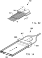
- Figure 13 shows a seventh alternative mouthpiece 702 that differs from the previously discussed mouthpiece 2 as shown in figures 1-5 in that it comprises a working surface 727 that is extendable from the suction inlet 721 in an extension direction D in line with the retaining path P for supporting at least a part of the section of hair 6 between the suction inlet 721 and the human head.
- Figure 14 shows a eighth alternative mouthpiece 802 that differs from the previously discussed mouthpiece 2 as shown in figures 1-5 in that it comprises one or more conduits 827, 828 that are connectable in fluid communication to a source of warm air, hot air, steam or liquid (not shown), wherein the one or more conduits 827, 828 debouch into the suction duct 823, preferably at or near the suction inlet 821.
- Figure 15 schematically shows a hairdressing shop 900 with a plurality of hairdressing chairs 901, 902, 903 and a plurality of the aforementioned hairdressing tools 1, 101 placed in close proximity to those chairs 901, 902, 903.
- Two of the hairdressing tools 1, 101 are provided with the previously discussed stand 30 that is arranged to be placed on the floor 990 of the hairdressing shop 900.
- Figure 15 shows a further hairdressing tool 201 that is provided with an alternative support 203 in the form of a mount 230 that is arranged to be mounted to a mounting surface of an object or a building, e.g. to a wall 991 or directly to one of the chairs 901, 902, 903.
- the hairdressing tools 1, 101, 201 in the hairdressing shop 900 of figure 15 form part of a hairdressing system 7.
- the suction unit 9 can be provided at the support 3, as with the hairdressing tool 1.
- the suction unit 9 may be provided separate from the support 3, as with the hairdressing tools 101, 201.
- the suction unit 9 is connected to in fluid communication to the respective first and second mouthpieces 2, 2' via the suction hose 8.
- the suction unit 9 When the suction unit 9 is separate from the support 3, it may be provided in a different room of the building, e.g. separated from the room where the hairdressing chairs 901, 902, 903 are located, to prevent noise.
- the suction unit 9 is provided with a filter 90 for separating cut-off hairs from the air flow.
- the hairdressing tool 1, 101, 201 can be used when cutting hairs.
Landscapes
- Dry Shavers And Clippers (AREA)
Description
- The invention relates to a hairdressing tool, a hairdressing system and a method for hairdressing.
- Conventional hairdressing involves performing complex manual positioning techniques, such as manipulation, gathering, selection and/or separation, on a section of hair to prepare said section or underlying sections of hair for the actual hairdressing techniques, such as cutting, coloring, shaping and/or providing attaching hair extensions. Hairdressers are extensively trained to perform the positioning techniques with one hand while executing the hairdressing techniques simultaneously with the other hand. This limits the ability of the hairdresser to execute accurate and/or complex hairdressing techniques.
- It is an object of the present invention to provide a hairdressing tool, a hairdressing system and a method for hairdressing that can simplify hairdressing. A hairdressing tool is for instance known from
US2014261525A1 . - A hairdressing tool according to the invention is defined by
claim 1. The hairdressing tool comprising a tirst mouthpiece, wherein the first mouthpiece comprises a suction inlet, a suction outlet, and a suction duct extending between the suction inlet and the suction outlet, wherein the suction outlet is connectable to a suction unit, wherein the suction inlet is arranged for sucking in a section of hair from the human head into the suction duct and wherein the suction duct is arranged for retaining said section of hair along a retaining path inside the suction duct wherein the suction inlet comprises an inlet opening with an inlet width and an inlet height, wherein the ratio between the inlet width and the inlet height is at least 10:1, preferably at least 15:1 and most preferably at least 20:1. - This results in a relatively wide suction inlet in which the section of hair can be spread out in the width direction to allow for precise and/or accurate hairdressing techniques.
- The suction duct defines a laminar flow area extending from the suction inlet towards the suction outlet along the retaining path, wherein the suction duct at the laminar flow area is formed so as to generate a laminar or a substantially laminar flow of air along said retaining path. Hence, the section of hair that is retained in said laminar flow area can be kept substantially stable and/or still, so that the hairdresser can accurately perform hairdressing techniques on said section of hair.
- The suction duct has a cross section perpendicular to the retaining path, which cross section is constant or substantially constant in the laminar flow area. Hence, the air flow rate can be kept substantially constant in said laminar flow area.
- In a preferred embodiment, the inlet height is less than ten millimeters, preferably less than eight millimeters and most preferably less than six millimeters
- In a further embodiment the suction duct has a duct height and a duct width, wherein the ratio between the duct width and the duct height is at least 10:1, preferably at least 15:1 and most preferably at least 20:1. In particular, the duct height is less than ten millimeters, preferably less than eight millimeters and most preferably less than six millimeters. Said duct is relatively wide, which can promote formation of a laminar air flow inside said suction duct.
- In a further embodiment the suction duct defines a retaining plane having a width of at least eight centimeters, preferably at least ten centimeters. Said width allows for the section of hair to be spread out across the retaining plane, to allow for precise and/or accurate hairdressing techniques on said section of hair.
- In a further embodiment the retaining path is linear. Hence, the section of hair can be retained in a substantially linear manner.
- Below is a list of optional features that could be incorporated either alone or in combination into the first mouthpiece or any of the further mouthpieces, if applicable.
- In an exemplary embodiment the first mouthpiece is at least partially transparent at the suction duct to allow visual inspection of the section of hair inside the suction duct from outside the first mouthpiece. Hence, the hairdresser can easily assess the condition of the section of hair and/or prepare said section of hair for the hairdressing techniques.
- Preferably, the first mouthpiece is provided with a magnification section located at the suction duct for visually inspecting the section of hair inside the suction duct from outside the first mouthpiece. The magnification section, e.g. a lens, can further increase the accuracy of the visual inspection. Preferably, the magnification is such that each hair in the section of hair can be inspected individually.
- In another embodiment the first mouthpiece is provided with one or more leveling instruments for visually indicating the orientation of the first mouthpiece relative to a horizontal and/or a vertical plane. Hence, the hairdresser can set the orientation of the first mouthpiece more accurately based on the feedback from the one or more leveling instruments.
- In a further embodiment the first mouthpiece comprises a laser for projecting a laser line and/or a laser pattern onto the section of hair retained in the first mouthpiece. The laser line and/or pattern can be used to more accurately position the first mouthpiece with respect to human head and/or to guide the hairdresser in performing the hairdressing techniques on the section of hair.
- In a further embodiment the first mouthpiece comprises one or more projections that are adjustable in length with respect to the suction inlet for setting a distance between the human head and the suction inlet. Hence, the section of hair can be retained more accurately, i.e. with the first mouthpiece at the a preset distance from the human head.
- In a further embodiment the first mouthpiece comprises a working surface that is extendable from the suction inlet in an extension direction in line with the retaining path for supporting at least a part of the section of hair between the suction inlet and the human head. The working surface can provide an effective working surface that can prevent the section of hair from slacking when performing hairdressing techniques.
- In a further embodiment the first mouthpiece comprises one or more conduits that are connectable in fluid communication to a source of warm air, hot air, steam or liquid, wherein the one or more conduits debouch into the suction duct, preferably at or near the suction inlet. Hence, the section of hair can be dried, heated, washed and/or colored while said section of hair is retained in the suction duct.
- In another embodiment, the hairdressing tool further comprises a support that is arranged for positioning the first mouthpiece with respect to a human head, wherein the hairdressing tool further comprises a fixation member for fixing the position of the first mouthpiece with respect to the support, wherein the hairdressing tool is arranged for hands-free retaining of said section of hair in the suction duct when the position of the first mouthpiece with respect to the support is fixed. The first mouthpiece can be conveniently set up for hands-free retaining of a section of hair to allow a hairdresser to perform hairdressing techniques, such as cutting, coloring, shaping and/or attaching hair extensions, on said section of hair or underlying sections of hair. There is no need for complex and simultaneously positioning techniques as in the prior art. Hence, a single hairdresser can execute complex hairdressing techniques with both hands and without the assistance of others.
- In a further embodiment thereof the first mouthpiece comprises an air chamber between the suction duct and the suction outlet, wherein the air chamber is formed so as to generate a turbulent flow of air between the suction duct and the suction outlet. Preferably, the air chamber has a cross section perpendicular to the retaining path that is larger than the cross section of the suction duct perpendicular to said retaining path. The turbulent air flow in the air chamber can isolate the mouthpiece from the sound waves that originate from the suction unit upstream of the suction outlet.
- In a preferred embodiment the support is a stand that is arranged to be placed on a floor. Hence, the support can be easily moved around over the floor with respect to the human head.
- In alternative embodiment the support is a mount that is arranged to be mounted to a mounting surface of an object or a building. This allows for the support to be mounted in a secure and/or stable manner. The support can for example be mounted to a wall, the ceiling or a hairdressing chair.
- In a further embodiment the first mouthpiece is coupled to the support via a coupling, wherein the coupling is arranged for rotating the first mouthpiece with respect to the support about a first axis of rotation. Preferably, the same coupling is also arranged for rotating the first mouthpiece with respect to the support about a second axis of rotation orthogonal to the first axis of rotation. Most preferably, the same coupling is additionally arranged for rotating the first mouthpiece with respect to the support about a third axis of rotation orthogonal to the first axis of rotation and the second axis of rotation. Hence, the first mouthpiece can be rotatable about one, two or even three axes of rotation so that the first mouthpiece can be positioned in many, if not any, orientation with respect to the support. Preferably, the coupling allows for three-dimensionally positioning the first mouthpiece relative to the human head.
- In a further embodiment the hairdressing tool comprises a second and/or further mouthpieces supported by the same support and arranged for retaining further sections of hair in different positions with respect to the support. Hence, several sections of hair can be retained simultaneously and hands-free by the respective mouthpieces, to allow for further and/or more complex hairdressing techniques.
- Alternatively or additionally, the hairdressing tool comprises a second and/or further mouthpieces, wherein the first mouthpiece and the second and/or further mouthpieces are interchangeable. Hence, the hairdresser can replace one mouthpiece by another mouthpiece depending on the hairdressing technique to be performed.
- According to a second aspect, the invention provides a hairdressing system comprising the hairdressing tool to according to the previously discussed embodiments that include the support, wherein the hairdressing system further comprises a suction unit at the support or separate from the support, wherein the suction unit is connectable in fluid communication to the suction outlet of the first mouthpiece.
- The suction unit is arranged to generate the suction in the suction duct to retain the section of hair. The suction unit can be connected to or placed near the support. Alternatively, the suction unit can be separated from the support, e.g. in a separate room, for reasons of noise isolation. One suction unit can be connected to several hairdressing tools simultaneously.
- In an embodiment thereof the hairdressing system comprises a suction hose for connecting the suction outlet of the first mouthpiece in fluid communication to the suction unit. The suction hose can be guided through and/or along the support to connect the suction outlet to the suction unit.
- In a further embodiment thereof the suction unit is provided with a filter for separating cut-off hairs from the air flow. Hence, in addition to retaining the section of hair, the first mouthpiece can also be used to suck in cut-off hairs to prevent said cut-off hairs from falling on the ground. The cut-off hairs can be collected centrally at the suction unit and can be disposed of regularly.
- The invention provides a method for hairdressing with the use of the hairdressing tool according to the invention, wherein the method comprises the step of:
- guiding the section of hair from the human head into the suction duct and retaining said section of hair along a retaining path inside the suction duct with suction.
- The invention provides a method for hairdressing with the use of the hairdressing tool according to the invention that includes the support, wherein the method comprises the steps of;
- guiding the section of hair from the human head into the suction duct and retaining said section of hair along a retaining path inside the suction duct with suction;
- using the fixation member to fix the position of the first mouthpiece with respect to the support; and
- performing hairdressing techniques on said section or underlying sections of hair while the section of hair is retained hands-free in the suction duct of the hairdressing tool.
- Hence, by employing the hairdressing tool according to the invention in the method according to the invention, the first mouthpiece can be conveniently set up for hands-free retaining of a section of hair to allow a hairdresser to perform hairdressing techniques, such as cutting, coloring and/or shaping, on said section of hair or underlying sections of hair. There is no need for complex and simultaneously positioning techniques as in the prior art. Hence, a single hairdresser can execute complex hairdressing techniques with both hands and without the assistance of others.
- In a preferred embodiment of the method, the hairdressing tool comprises a second and/or further mouthpieces supported by the same support, wherein the method further comprises the step of retaining further sections of hair in different positions with respect to the support. Hence, several sections of hair can be retained simultaneously and hands-free by the respective mouthpieces, to allow for further and/or more complex hairdressing techniques.
- Alternatively or additionally, the hairdressing tool comprises a second and/or further mouthpieces, wherein the method further comprises the step of interchanging the first mouthpiece and the second and/or further mouthpieces. Hence, the hairdresser can replace one mouthpiece by another mouthpiece depending on the hairdressing technique to be performed.
- The various aspects and features described and shown in the specification can be applied, individually, wherever possible. These individual aspects, in particular the aspects and features described in the attached dependent claims, can be made subject of divisional patent applications.
- The invention will be elucidated on the basis of an exemplary embodiment shown in the attached schematic drawings, in which:
-
figure 1 shows a side view of a hairdressing tool with a first mouthpiece according to a first embodiment of the invention; -
figure 2 shows an isometric view of the first mouthpiece according tofigure 1 ; -
figure 3 shows an isometric view of the first mouthpiece according tofigure 2 while retaining a section of hair; -
figure 4 shows a cross section of the first mouthpiece according to the line IV-IV infigure 3 ; -
figure 5 shows a top view of the first mouthpiece according tofigure 3 ; -
figure 6 shows an alternative hairdressing tool with a first mouthpiece and a second mouthpiece according to a second embodiment of the invention; -
figures 7-14 show various embodiments of the first mouthpiece with optional features that could be incorporated either alone or in combination into the first mouthpiece or any of the further mouthpieces, if applicable; and -
figure 15 show a hairdressing system comprising several hairdressing tools according to a third embodiment of the invention. -
Figures 1-5 show ahairdressing tool 1 according to a first exemplary embodiment of the invention. Thehairdressing tool 1 is used for hands-free retaining of a section ofhair 6, as shown infigure 3 . 'Hands-free retaining' in the context of the present invention means retaining without the use of hands, so that the hairdresser has both hands available for performing other hairdressing on the retained section ofhair 6 or the underlying section of hair. - As shown in
figure 1 , thehairdressing tool 1 comprises afirst mouthpiece 2 and asupport 3 that is arranged for positioning thefirst mouthpiece 2 with respect to a human head, for example in the orientation as shown infigure 3 . Thefirst mouthpiece 2 is coupled to thesupport 3 via acoupling 4, in this exemplary embodiment in the form of aflexible suction hose 8, that is arranged for rotating thefirst mouthpiece 2 with respect to thesupport 3 about a first axis of rotation X. Alternatively, thecoupling 4 may be a hinge-like coupling with one or more degrees of freedom, in which case theflexible suction hose 8 is separately attached to thefirst mouthpiece 2. Preferably, thecoupling 4 is arranged for rotating thefirst mouthpiece 2 with respect to thesupport 3 about a second axis of rotation Y orthogonal to the first axis of rotation X. Most preferably, thecoupling 4 is arranged for rotating thefirst mouthpiece 2 with respect to the support about a third axis of rotation R orthogonal to the first axis of rotation X and the second axis of rotation Y. Hence, saidcoupling 4 provides considerable degrees of freedom for positioning thefirst mouthpiece 2 with respect to a human head. - The
hairdressing tool 1 further comprises afixation member 5 that is arranged to fixate thefirst mouthpiece 2 in a set position with respect to thesupport 3. Thehairdressing tool 1 is arranged for hands-free retaining of said section ofhair 6 in thesuction duct 23 when the position of thefirst mouthpiece 2 with respect to thesupport 3 is fixed. In this exemplary embodiment, thefixation member 5 is a plastically deformable,stiff element 50 running alongside and/or parallel to thecoupling 4 between thefirst mouthpiece 2 and thesupport 3.Said fixation member 5 is sufficiently stiff to support the weight of thefirst mouthpiece 2 and to maintain the position thereof relative to thesupport 3. When additional manual force is applied, the positioning of thefirst mouthpiece 2 with respect to thesupport 3 can be conveniently altered. Alternatively, mechanical fasteners, such as wing nuts or clamps can be used to fixate the position of thefirst mouthpiece 2 with respect to thesupport 3. - As shown in
figures 1-5 , thefirst mouthpiece 2 comprises amouthpiece body 20 with asuction inlet 21, asuction outlet 22, and asuction duct 23 extending between thesuction inlet 21 and thesuction outlet 22. Thesuction outlet 22 is connectable via thesuction hose 8 to asuction unit 9, as for example shown infigure 15 . Saidsuction unit 9 is arranged for generating an low pressure or partial vacuum for drawing ambient air into thesuction inlet 21, through thesuction duct 23 and out of thesuction outlet 22. The capacity of thesuction unit 9 is sufficient to generate an air flow rate inside thesuction duct 23 that is sufficient to reliably retain the section ofhair 6 inside thefirst mouthpiece 2. - As shown in
figures 2 and 3 , thesuction inlet 21 has aninlet opening 24 that is dimensioned and/or shaped to suck the section ofhair 6 into thesuction duct 23 when said section ofhair 6 is presented by the hairdresser in the proximity of saidinlet opening 24. Thesuction duct 23 is arranged for retaining said section ofhair 6 along a retaining path P inside thesuction duct 23. As best seen infigure 4 , thesuction duct 23 defines alaminar flow area 25 extending from thesuction inlet 21 towards thesuction outlet 22 along the retaining path P. Thesuction duct 23 at thelaminar flow area 25 is formed so as to generate a laminar or a substantially laminar flow of air A along said retaining path P. To achieve said laminar flow of air A, thesuction duct 23 has a cross section perpendicular to the retaining path P, which cross section is constant or substantially constant in thelaminar flow area 25. In this exemplary embodiment, the retaining path P inside thesuction duct 23 is linear or substantially linear. - The
suction duct 23 has a ratio between the duct height H and a duct width W of at least 10:1, preferably at least 15:1 and most preferably at least 20:1. In this exemplary embodiment, the duct height H is less than ten millimeters, preferably less than eight millimeters and most preferably less than six millimeters. As shown infigure 5 , thesuction duct 23 further defines a retaining plane K having a width of at least eight centimeters, preferably at least ten centimeters. - To prevent any turbulence generation between the
inlet opening 24 and thesuction duct 23, it is preferred that theinlet opening 24 has the same ratio and or the same dimensions as thesuction duct 23. Therefore, in this exemplary embodiment, the inlet height is equal to the duct height H and is less than ten millimeters, preferably less than eight millimeters and most preferably less than six millimeters. - In the embodiment as shown in
figures 1-5 , thefirst mouthpiece 2 comprises anair chamber 26 between thesuction duct 23 and thesuction outlet 22. Theair chamber 26 is formed so as to generate a turbulent flow of air T between thesuction duct 23 and thesuction outlet 22. The turbulent flow of air T interrupts the sound waves originating from thesuction unit 9 and can thus reduce the noise of thesuction unit 9 that is perceived at thefirst mouthpiece 2. In this exemplary embodiment, theair chamber 26 has a cross section perpendicular to the retaining path P that is larger than the cross section of thesuction duct 23 perpendicular to said retaining path P. - The
first mouthpiece 2 is preferably at least partially transparent at thesuction duct 23 to allow visual inspection of the section ofhair 6 inside thesuction duct 23 from outside thefirst mouthpiece 2. -
Figure 6 shows an alternative embodiment of thehairdressing tool 101 that comprise thefirst mouthpiece 2 offigures 1-5 and a second mouthpiece 2' and/or further mouthpieces supported by thesame support 3 and arranged for retaining further sections of hair in different positions with respect to thesupport 3. Saidalternative hairdressing tool 101 is provided with anadapter 110 for mounting the twomouthpieces 2, 2' to thesame suction hose 8. - The one or
more mouthpieces 2, 2' of thehairdressing tool 1 are interchangeable depending on the hairdressing techniques that are to be performed.Figures 7-14 show a variety offurther mouthpieces coupling 4 of thehairdressing tool 1 instead of the previously describedfirst mouthpiece 2. -
Figure 7 shows an unclaimed firstalternative mouthpiece 102 that differs from thefirst mouthpiece 2 as shown infigures 1-5 in that itssuction duct 123 extends along a non-linear retaining path P. In this example, the retaining path P is at least partially helical. Said retaining path P can be used to shape the section ofhair 6 into a curl. In an alternative embodiment (not shown), the retaining path P may be corrugated to shape the section ofhair 6 into a wave pattern. Other non-linear paths P may be provided depending on the hairdressing requirements. -
Figure 8 shows an unclaimed secondalternative mouthpiece 202 that differs from thefirst mouthpiece 2 as shown infigures 1-5 in that it has three individual orseparate suction ducts 223 that extend parallel or substantially parallel to each other along respective retaining paths P1, P2, P3. Eachsuction duct 223 is arranged for retaining a section ofhair suction ducts 223 prior to the retaining, said elastic bands E can be slid off thealternative mouthpiece 202 and onto the retained sections ofhair alternative mouthpiece 202 offigure 8 provides a convenient way of applying elastic bands E around sections ofhair -
Figure 9 shows a thirdalternative mouthpiece 302 that differs from the previously discussedmouthpiece 2 as shown infigures 1-5 in that it is provided with amagnification section 327 located at thesuction duct 323 for visually inspecting the section ofhair 6 inside thesuction duct 323 from outside thealternative mouthpiece 302. -
Figure 10 shows a fourthalternative mouthpiece 402 that differs from the previously discussedmouthpiece 2 as shown infigures 1-5 in that it is provided with alaser 427 on themouthpiece body 420 for projecting a laser line L and/or a laser pattern onto the section ofhair 6 retained in thealternative mouthpiece 402. -
Figure 11 shows a fifthalternative mouthpiece 502 that differs from the previously discussedmouthpiece 2 as shown infigures 1-5 in that it is provided with one ormore leveling instruments 527 for visually indicating the orientation of thealternative mouthpiece 502 relative to a horizontal and/or a vertical plane. -
Figure 12 shows a sixthalternative mouthpiece 602 that differs from the previously discussedmouthpiece 2 as shown infigures 1-5 in that it comprises one ormore projections -
Figure 13 shows a seventhalternative mouthpiece 702 that differs from the previously discussedmouthpiece 2 as shown infigures 1-5 in that it comprises a workingsurface 727 that is extendable from thesuction inlet 721 in an extension direction D in line with the retaining path P for supporting at least a part of the section ofhair 6 between thesuction inlet 721 and the human head. -
Figure 14 shows a eighthalternative mouthpiece 802 that differs from the previously discussedmouthpiece 2 as shown infigures 1-5 in that it comprises one ormore conduits more conduits suction duct 823, preferably at or near thesuction inlet 821. -
Figure 15 schematically shows ahairdressing shop 900 with a plurality of hairdressing chairs 901, 902, 903 and a plurality of theaforementioned hairdressing tools chairs hairdressing tools stand 30 that is arranged to be placed on thefloor 990 of thehairdressing shop 900.Figure 15 shows afurther hairdressing tool 201 that is provided with analternative support 203 in the form of amount 230 that is arranged to be mounted to a mounting surface of an object or a building, e.g. to awall 991 or directly to one of thechairs - The
hairdressing tools hairdressing shop 900 offigure 15 form part of ahairdressing system 7. In saidhairdressing system 7, thesuction unit 9 can be provided at thesupport 3, as with thehairdressing tool 1. Alternatively, thesuction unit 9 may be provided separate from thesupport 3, as with thehairdressing tools suction unit 9 is connected to in fluid communication to the respective first andsecond mouthpieces 2, 2' via thesuction hose 8. When thesuction unit 9 is separate from thesupport 3, it may be provided in a different room of the building, e.g. separated from the room where the hairdressing chairs 901, 902, 903 are located, to prevent noise. - Preferably, the
suction unit 9 is provided with afilter 90 for separating cut-off hairs from the air flow. Hence, thehairdressing tool - It is to be understood that the above description is included to illustrate the operation of the preferred embodiments and is not meant to limit the scope of the invention. From the above discussion, many variations will be apparent to one skilled in the art that would yet be encompassed by the scope of the present invention.
Claims (16)
- Hairdressing tool (1, 101, 201) comprising a first mouthpiece (2, 302, 402, 502, 602, 702, 802), wherein the first mouthpiece comprises a mouthpiece body (20, 420) with a suction inlet (21, 721, 821), a suction outlet (22), and a suction duct (23, 323) extending between the suction inlet (21, 721, 821) and the suction outlet (22), wherein the suction outlet (22) is connectable to a suction unit (9), wherein the suction inlet (21, 721, 821) is arranged for sucking in a section of hair (6) from the human head into the suction duct (23, 323) and wherein the suction duct (23, 323) is arranged for retaining said section of hair (6) along a retaining path (P) inside the suction duct (23, 323), wherein the mouthpiece body (20, 420) is continuous between the suction inlet (21, 721, 821) and the suction outlet (22) such that the suction duct (23, 323) is open only at the suction inlet (21, 721, 821) and the suction outlet (22), wherein the suction inlet (21, 721, 821) comprises an inlet opening (24) with an inlet width (W) and an inlet height (H), characterized in that the ratio between the inlet width (W) and the inlet height (H) is at least 10:1, wherein the suction duct (23, 323) defines a laminar flow area (25) extending from the suction inlet (21, 721, 821) towards the suction outlet (22) along the retaining path (P), wherein the suction duct (23, 323) at the laminar flow area (25) has a cross section perpendicular to the retaining path (P) that is constant or substantially constant in the laminar flow area (25) so as to generate a laminar or a substantially laminar flow of air along said retaining path (P).
- Hairdressing tool (1, 101, 201) according to claim 1, wherein the ratio between the inlet width (W) and the inlet height (H) is at least 15:1 and preferably at least 20:1.
- Hairdressing tool (1, 101, 201) according to any one of the preceding claims, wherein the inlet height (H) is less than ten millimeters, preferably less than eight millimeters and most preferably less than six millimeters.
- Hairdressing tool (1, 101, 201) according to any one of the preceding claims, wherein the suction duct (23, 323) has a duct height (H) and a duct width (W), wherein the ratio between the duct width (W) and the duct height (H) is at least 10:1, preferably at least 15:1 and most preferably at least 20:1, preferably wherein the duct height (H) is less than ten millimeters, preferably less than eight millimeters and most preferably less than six millimeters, more preferably wherein the suction duct (23, 323) defines a retaining plane (K) having a width of at least eight centimeters, preferably at least ten centimeters.
- Hairdressing tool (1, 101, 201) according to any one of the preceding claims, wherein the retaining path (P) is linear.
- Hairdressing tool (1, 101, 201) according to any one of the preceding claims, wherein the first mouthpiece (2, 302, 402, 502, 602, 702, 802) comprises an air chamber (26) between the suction duct (23, 323) and the suction outlet (22), wherein the air chamber (26) is formed so as to generate a turbulent flow of air between the suction duct (23, 323) and the suction outlet (22), preferably wherein the air chamber (26) has a cross section perpendicular to the retaining path (P) that is larger than the cross section of the suction duct (23, 323) perpendicular to said retaining path (P).
- Hairdressing tool (1, 101, 201) according to any one of the preceding claims, wherein the first mouthpiece (2, 302, 402, 502, 602, 702, 802) is at least partially transparent at the suction duct (23, 323) to allow visual inspection of the section of hair (6) inside the suction duct (23, 323) from outside the first mouthpiece (2, 302, 402, 502, 602, 702, 802), preferably wherein the first mouthpiece (302) is provided with a magnification section (327) located at the suction duct (323) for visually inspecting the section of hair (6) inside the suction duct (323) from outside the first mouthpiece (302).
- Hairdressing tool (1, 101, 201) according to any one of the preceding claims, wherein the first mouthpiece (502) is provided with one or more leveling instruments (527) for visually indicating the orientation of the first mouthpiece (502) relative to a horizontal and/or a vertical plane; or wherein the first mouthpiece (402) comprises a laser (427) for projecting a laser line (L) and/or a laser pattern onto the section of hair (6) retained in the first mouthpiece (402).
- Hairdressing tool (1, 101, 201) according to any one of the preceding claims, wherein the first mouthpiece (602) comprises one or more projections (627, 628) that are adjustable in length with respect to the suction inlet (21) for setting a distance between the human head and the suction inlet (21); or wherein the first mouthpiece (702) comprises a working surface (727) that is extendable from the suction inlet (721) in an extension direction (D) in line with the retaining path (P) for supporting at least a part of the section of hair (6) between the suction inlet (721) and the human head.
- Hairdressing tool (1, 101, 201) according to any one of the preceding claims, wherein the first mouthpiece (802) comprises one or more conduits (827, 828) that are connectable in fluid communication to a source of warm air, hot air, steam or liquid, wherein the one or more conduits (827, 828) debouch into the suction duct (823), preferably at or near the suction inlet (821).
- Hairdressing tool (1, 101, 201) according to any one of the preceding claims, wherein the hairdressing tool further comprises a support (3, 203) that is arranged for positioning the first mouthpiece (2, 302, 402, 502, 602, 702, 802) with respect to a human head, wherein the hairdressing tool (1, 101, 201) further comprises a fixation member (5) for fixing the position of the first mouthpiece (2, 302, 402, 502, 602, 702, 802) with respect to the support (3, 203), wherein the hairdressing tool (1, 101, 201) is arranged for hands-free retaining of said section of hair (6) in the suction duct (23, 323) when the position of the first mouthpiece (2, 302, 402, 502, 602, 702, 802) with respect to the support (3, 203) is fixed, preferably wherein the support (3) is a stand (30) that is arranged to be placed on a floor (990), or wherein the support (203) is a mount (230) that is arranged to be mounted to a mounting surface of an object (991, 901, 902, 903) or a building.
- Hairdressing tool (1, 101, 201) according to claim 11, wherein the first mouthpiece (2, 302, 402, 502, 602, 702, 802) is coupled to the support (3, 203) via a coupling (4), wherein the coupling (4) is arranged for rotating the first mouthpiece (2, 302, 402, 502, 602, 702, 802) with respect to the support (3, 203) about a first axis of rotation (X), preferably wherein the coupling (4) is arranged for rotating the first mouthpiece (2, 302, 402, 502, 602, 702, 802) with respect to the support (3, 203) about a second axis of rotation (Y) orthogonal to the first axis of rotation (X), more preferably wherein the coupling (4) is arranged for rotating the first mouthpiece (2, 302, 402, 502, 602, 702, 802) with respect to the support (3, 203) about a third axis of rotation (R) orthogonal to the first axis of rotation (X) and the second axis of rotation (Y) .
- Hairdressing tool (101) according to claim 11 or 12, wherein the hairdressing tool (101) comprises a second and/or further mouthpieces (2') supported by the same support (3, 203) and arranged for retaining further sections of hair (6) in different positions with respect to the support (3, 203); or wherein the hairdressing tool (101) comprises a second and/or further mouthpieces (2'), wherein the first mouthpiece (2, 302, 402, 502, 602, 702, 802) and the second and/or further mouthpieces (2') are interchangeable.
- Hairdressing system (7) comprising the hairdressing tool (1, 101, 201) according to any one of claims 11-13, wherein the hairdressing system (7) further comprises a suction unit (9) at the support (3, 203) or separate from the support (3, 203), wherein the suction unit (9) is connectable in fluid communication to the suction outlet (22) of the first mouthpiece (2, 302, 402, 502, 602, 702, 802), preferably wherein the hairdressing system (7) comprises a suction hose (8) for connecting the suction outlet (22) of the first mouthpiece (2, 302, 402, 502, 602, 702, 802) in fluid communication to the suction unit (9), more preferably wherein the suction unit (9) is provided with a filter (90) for separating cut-off hairs from the air flow.
- Method for hairdressing with the use of the hairdressing tool (1, 101, 201) according to any one of claims 1-13, wherein the method comprises the step of:- guiding the section of hair (6) from the human head into the suction duct (23, 323) and retaining said section of hair (6) along a retaining path (P) inside the suction duct (23, 323) with suction.
- Method for hairdressing with the use of the hairdressing tool (1, 101, 201) according to any one of claims 11-13, wherein the method comprises the steps of:- guiding the section of hair (6) from the human head into the suction duct (23, 323) and retaining said section of hair (6) along a retaining path (P) inside the suction duct (23, 323) with suction;- using the fixation member (5) to fix the position of the first mouthpiece (2, 302, 402, 502, 602, 702, 802) with respect to the support (3, 203); and- performing hairdressing techniques on said section (6) or underlying sections of hair while the section of hair (6) is retained hands-free in the suction duct (23, 323) of the hairdressing tool (1, 101, 201), preferably wherein the hairdressing tool (101) comprises a second and/or further mouthpieces (2') supported by the same support (3, 203), wherein the method further comprises the step of retaining further sections of hair (6) in different positions with respect to the support (3, 203), or wherein the hairdressing tool (101) comprises a second and/or further mouthpieces (2'), wherein the method further comprises the step of interchanging the first mouthpiece (2, 302, 402, 502, 602, 702, 802) and the second and/or further mouthpieces (2').
Applications Claiming Priority (2)
| Application Number | Priority Date | Filing Date | Title |
|---|---|---|---|
| NL2018079A NL2018079B1 (en) | 2016-12-23 | 2016-12-23 | Hairdressing tool, hairdressing system and method for hairdressing |
| PCT/NL2017/050843 WO2018117819A1 (en) | 2016-12-23 | 2017-12-18 | Hairdressing tool, hairdressing system and method for hairdressing |
Publications (3)
| Publication Number | Publication Date |
|---|---|
| EP3558051A1 EP3558051A1 (en) | 2019-10-30 |
| EP3558051C0 EP3558051C0 (en) | 2024-02-21 |
| EP3558051B1 true EP3558051B1 (en) | 2024-02-21 |
Family
ID=60888575
Family Applications (1)
| Application Number | Title | Priority Date | Filing Date |
|---|---|---|---|
| EP17822802.9A Active EP3558051B1 (en) | 2016-12-23 | 2017-12-18 | Hairdressing tool, hairdressing system and method for hairdressing |
Country Status (3)
| Country | Link |
|---|---|
| EP (1) | EP3558051B1 (en) |
| NL (1) | NL2018079B1 (en) |
| WO (1) | WO2018117819A1 (en) |
Families Citing this family (1)
| Publication number | Priority date | Publication date | Assignee | Title |
|---|---|---|---|---|
| CN111789370B (en) * | 2020-06-19 | 2023-03-28 | 安徽医科大学 | Hair picking device for hair extension |
Citations (1)
| Publication number | Priority date | Publication date | Assignee | Title |
|---|---|---|---|---|
| US4974321A (en) * | 1988-04-22 | 1990-12-04 | Takaaki Yoshida | Hair cutting device |
Family Cites Families (3)
| Publication number | Priority date | Publication date | Assignee | Title |
|---|---|---|---|---|
| US4000562A (en) * | 1975-05-29 | 1977-01-04 | Alevras Constantino J | Vacuum haircutting apparatus and method |
| US6925728B2 (en) * | 2002-03-12 | 2005-08-09 | Kathleen M. Busa | Grooming device with vacuum for drying and straightening hair |
| US8887738B2 (en) * | 2013-03-18 | 2014-11-18 | Tina Ward | Suction powered hair-styling device |
-
2016
- 2016-12-23 NL NL2018079A patent/NL2018079B1/en not_active IP Right Cessation
-
2017
- 2017-12-18 WO PCT/NL2017/050843 patent/WO2018117819A1/en not_active Ceased
- 2017-12-18 EP EP17822802.9A patent/EP3558051B1/en active Active
Patent Citations (1)
| Publication number | Priority date | Publication date | Assignee | Title |
|---|---|---|---|---|
| US4974321A (en) * | 1988-04-22 | 1990-12-04 | Takaaki Yoshida | Hair cutting device |
Also Published As
| Publication number | Publication date |
|---|---|
| EP3558051C0 (en) | 2024-02-21 |
| WO2018117819A1 (en) | 2018-06-28 |
| NL2018079B1 (en) | 2018-07-02 |
| EP3558051A1 (en) | 2019-10-30 |
Similar Documents
| Publication | Publication Date | Title |
|---|---|---|
| JP3204344U (en) | Suitable for application of methods for keeping the reflective surface of a mirror with a handle for medical or dental testing clean during use by an manipulated air flow, improved to a more easily sterilizable of the handle mirror Configuration | |
| US10307921B2 (en) | Automated hair cutting system and method of operation thereof | |
| CN206136994U (en) | Unmanned aerial vehicle sprays scope adjusting device | |
| US5813088A (en) | Backpack blower | |
| JP2019130532A (en) | Instrument head cleaning system | |
| EP3558051B1 (en) | Hairdressing tool, hairdressing system and method for hairdressing | |
| KR101479369B1 (en) | Equipment of dispersing air jets from air conditioning systems and mixing them with ambient air | |
| US20220071748A1 (en) | Evacuation dam frame | |
| US20110179597A1 (en) | Debris collecting apparatus and methods of making and using the same | |
| KR20190041468A (en) | An ultra-portable system for isolation and control during surgery in surgical environments | |
| US4077122A (en) | Hair cutting and trimming apparatus | |
| CA2849113A1 (en) | Floor stand with angled arm for microscope | |
| WO2017058507A3 (en) | Portable, controlled environment system | |
| EP1210955A3 (en) | Breast pump and regulating device, distribution valve, pump therefor | |
| JP7359397B2 (en) | haircut device | |
| FR3104917B1 (en) | IMPROVED HAIRDRESSING DEVICE FORMING AN OSCILLATING BLOWING BRUSH | |
| CN106041692B (en) | sanding tool | |
| JP2009180457A (en) | Clean air conditioner | |
| CN210662976U (en) | Range hood slit air curtain structure and range hood | |
| JP5278925B1 (en) | Auxiliary hose for vacuum cleaner | |
| WO2008058538A1 (en) | A personal climatic device and system for its supply | |
| SE440760B (en) | HARKLIPPNINGSANORDNING | |
| CN111771711A (en) | Pose and pose calculation method and pose calculation device of pollination robot and its robotic arm | |
| FR2856637B1 (en) | VENTILATION, HEATING AND / OR AIR CONDITIONING DEVICE COMPRISING AN AIR PROPULSION MEMBER, A SEAT AND A CONNECTION DUCT BETWEEN THE BODY AND THE SEAT | |
| US20230204204A1 (en) | Lighting System With Vacuum Intake |
Legal Events
| Date | Code | Title | Description |
|---|---|---|---|
| STAA | Information on the status of an ep patent application or granted ep patent |
Free format text: STATUS: UNKNOWN |
|
| STAA | Information on the status of an ep patent application or granted ep patent |
Free format text: STATUS: THE INTERNATIONAL PUBLICATION HAS BEEN MADE |
|
| PUAI | Public reference made under article 153(3) epc to a published international application that has entered the european phase |
Free format text: ORIGINAL CODE: 0009012 |
|
| STAA | Information on the status of an ep patent application or granted ep patent |
Free format text: STATUS: REQUEST FOR EXAMINATION WAS MADE |
|
| 17P | Request for examination filed |
Effective date: 20190722 |
|
| AK | Designated contracting states |
Kind code of ref document: A1 Designated state(s): AL AT BE BG CH CY CZ DE DK EE ES FI FR GB GR HR HU IE IS IT LI LT LU LV MC MK MT NL NO PL PT RO RS SE SI SK SM TR |
|
| AX | Request for extension of the european patent |
Extension state: BA ME |
|
| DAV | Request for validation of the european patent (deleted) | ||
| DAX | Request for extension of the european patent (deleted) | ||
| STAA | Information on the status of an ep patent application or granted ep patent |
Free format text: STATUS: EXAMINATION IS IN PROGRESS |
|
| 17Q | First examination report despatched |
Effective date: 20220421 |
|
| INTG | Intention to grant announced |
Effective date: 20221215 |
|
| GRAJ | Information related to disapproval of communication of intention to grant by the applicant or resumption of examination proceedings by the epo deleted |
Free format text: ORIGINAL CODE: EPIDOSDIGR1 |
|
| INTC | Intention to grant announced (deleted) | ||
| GRAP | Despatch of communication of intention to grant a patent |
Free format text: ORIGINAL CODE: EPIDOSNIGR1 |
|
| STAA | Information on the status of an ep patent application or granted ep patent |
Free format text: STATUS: GRANT OF PATENT IS INTENDED |
|
| INTG | Intention to grant announced |
Effective date: 20230918 |
|
| GRAS | Grant fee paid |
Free format text: ORIGINAL CODE: EPIDOSNIGR3 |
|
| GRAA | (expected) grant |
Free format text: ORIGINAL CODE: 0009210 |
|
| STAA | Information on the status of an ep patent application or granted ep patent |
Free format text: STATUS: THE PATENT HAS BEEN GRANTED |
|
| AK | Designated contracting states |
Kind code of ref document: B1 Designated state(s): AL AT BE BG CH CY CZ DE DK EE ES FI FR GB GR HR HU IE IS IT LI LT LU LV MC MK MT NL NO PL PT RO RS SE SI SK SM TR |
|
| REG | Reference to a national code |
Ref country code: GB Ref legal event code: FG4D |
|
| REG | Reference to a national code |
Ref country code: CH Ref legal event code: EP |
|
| REG | Reference to a national code |
Ref country code: IE Ref legal event code: FG4D |
|
| REG | Reference to a national code |
Ref country code: DE Ref legal event code: R096 Ref document number: 602017079391 Country of ref document: DE |
|
| U01 | Request for unitary effect filed |
Effective date: 20240228 |
|
| U07 | Unitary effect registered |
Designated state(s): AT BE BG DE DK EE FI FR IT LT LU LV MT NL PT SE SI Effective date: 20240306 |
|
| PG25 | Lapsed in a contracting state [announced via postgrant information from national office to epo] |
Ref country code: IS Free format text: LAPSE BECAUSE OF FAILURE TO SUBMIT A TRANSLATION OF THE DESCRIPTION OR TO PAY THE FEE WITHIN THE PRESCRIBED TIME-LIMIT Effective date: 20240621 |
|
| PG25 | Lapsed in a contracting state [announced via postgrant information from national office to epo] |
Ref country code: GR Free format text: LAPSE BECAUSE OF FAILURE TO SUBMIT A TRANSLATION OF THE DESCRIPTION OR TO PAY THE FEE WITHIN THE PRESCRIBED TIME-LIMIT Effective date: 20240522 |
|
| PG25 | Lapsed in a contracting state [announced via postgrant information from national office to epo] |
Ref country code: RS Free format text: LAPSE BECAUSE OF FAILURE TO SUBMIT A TRANSLATION OF THE DESCRIPTION OR TO PAY THE FEE WITHIN THE PRESCRIBED TIME-LIMIT Effective date: 20240521 Ref country code: HR Free format text: LAPSE BECAUSE OF FAILURE TO SUBMIT A TRANSLATION OF THE DESCRIPTION OR TO PAY THE FEE WITHIN THE PRESCRIBED TIME-LIMIT Effective date: 20240221 |
|
| PG25 | Lapsed in a contracting state [announced via postgrant information from national office to epo] |
Ref country code: ES Free format text: LAPSE BECAUSE OF FAILURE TO SUBMIT A TRANSLATION OF THE DESCRIPTION OR TO PAY THE FEE WITHIN THE PRESCRIBED TIME-LIMIT Effective date: 20240221 |
|
| PG25 | Lapsed in a contracting state [announced via postgrant information from national office to epo] |
Ref country code: RS Free format text: LAPSE BECAUSE OF FAILURE TO SUBMIT A TRANSLATION OF THE DESCRIPTION OR TO PAY THE FEE WITHIN THE PRESCRIBED TIME-LIMIT Effective date: 20240521 Ref country code: NO Free format text: LAPSE BECAUSE OF FAILURE TO SUBMIT A TRANSLATION OF THE DESCRIPTION OR TO PAY THE FEE WITHIN THE PRESCRIBED TIME-LIMIT Effective date: 20240521 Ref country code: IS Free format text: LAPSE BECAUSE OF FAILURE TO SUBMIT A TRANSLATION OF THE DESCRIPTION OR TO PAY THE FEE WITHIN THE PRESCRIBED TIME-LIMIT Effective date: 20240621 Ref country code: HR Free format text: LAPSE BECAUSE OF FAILURE TO SUBMIT A TRANSLATION OF THE DESCRIPTION OR TO PAY THE FEE WITHIN THE PRESCRIBED TIME-LIMIT Effective date: 20240221 Ref country code: GR Free format text: LAPSE BECAUSE OF FAILURE TO SUBMIT A TRANSLATION OF THE DESCRIPTION OR TO PAY THE FEE WITHIN THE PRESCRIBED TIME-LIMIT Effective date: 20240522 Ref country code: ES Free format text: LAPSE BECAUSE OF FAILURE TO SUBMIT A TRANSLATION OF THE DESCRIPTION OR TO PAY THE FEE WITHIN THE PRESCRIBED TIME-LIMIT Effective date: 20240221 |
|
| PG25 | Lapsed in a contracting state [announced via postgrant information from national office to epo] |
Ref country code: PL Free format text: LAPSE BECAUSE OF FAILURE TO SUBMIT A TRANSLATION OF THE DESCRIPTION OR TO PAY THE FEE WITHIN THE PRESCRIBED TIME-LIMIT Effective date: 20240221 |
|
| PG25 | Lapsed in a contracting state [announced via postgrant information from national office to epo] |
Ref country code: PL Free format text: LAPSE BECAUSE OF FAILURE TO SUBMIT A TRANSLATION OF THE DESCRIPTION OR TO PAY THE FEE WITHIN THE PRESCRIBED TIME-LIMIT Effective date: 20240221 |
|
| PG25 | Lapsed in a contracting state [announced via postgrant information from national office to epo] |
Ref country code: SM Free format text: LAPSE BECAUSE OF FAILURE TO SUBMIT A TRANSLATION OF THE DESCRIPTION OR TO PAY THE FEE WITHIN THE PRESCRIBED TIME-LIMIT Effective date: 20240221 |
|
| PG25 | Lapsed in a contracting state [announced via postgrant information from national office to epo] |
Ref country code: CZ Free format text: LAPSE BECAUSE OF FAILURE TO SUBMIT A TRANSLATION OF THE DESCRIPTION OR TO PAY THE FEE WITHIN THE PRESCRIBED TIME-LIMIT Effective date: 20240221 |
|
| PG25 | Lapsed in a contracting state [announced via postgrant information from national office to epo] |
Ref country code: SK Free format text: LAPSE BECAUSE OF FAILURE TO SUBMIT A TRANSLATION OF THE DESCRIPTION OR TO PAY THE FEE WITHIN THE PRESCRIBED TIME-LIMIT Effective date: 20240221 |
|
| PG25 | Lapsed in a contracting state [announced via postgrant information from national office to epo] |
Ref country code: SM Free format text: LAPSE BECAUSE OF FAILURE TO SUBMIT A TRANSLATION OF THE DESCRIPTION OR TO PAY THE FEE WITHIN THE PRESCRIBED TIME-LIMIT Effective date: 20240221 Ref country code: SK Free format text: LAPSE BECAUSE OF FAILURE TO SUBMIT A TRANSLATION OF THE DESCRIPTION OR TO PAY THE FEE WITHIN THE PRESCRIBED TIME-LIMIT Effective date: 20240221 Ref country code: RO Free format text: LAPSE BECAUSE OF FAILURE TO SUBMIT A TRANSLATION OF THE DESCRIPTION OR TO PAY THE FEE WITHIN THE PRESCRIBED TIME-LIMIT Effective date: 20240221 Ref country code: CZ Free format text: LAPSE BECAUSE OF FAILURE TO SUBMIT A TRANSLATION OF THE DESCRIPTION OR TO PAY THE FEE WITHIN THE PRESCRIBED TIME-LIMIT Effective date: 20240221 |
|
| REG | Reference to a national code |
Ref country code: DE Ref legal event code: R097 Ref document number: 602017079391 Country of ref document: DE |
|
| PLBE | No opposition filed within time limit |
Free format text: ORIGINAL CODE: 0009261 |
|
| STAA | Information on the status of an ep patent application or granted ep patent |
Free format text: STATUS: NO OPPOSITION FILED WITHIN TIME LIMIT |
|
| U20 | Renewal fee for the european patent with unitary effect paid |
Year of fee payment: 8 Effective date: 20241212 |
|
| 26N | No opposition filed |
Effective date: 20241122 |
|
| PG25 | Lapsed in a contracting state [announced via postgrant information from national office to epo] |
Ref country code: MC Free format text: LAPSE BECAUSE OF FAILURE TO SUBMIT A TRANSLATION OF THE DESCRIPTION OR TO PAY THE FEE WITHIN THE PRESCRIBED TIME-LIMIT Effective date: 20240221 |
|
| REG | Reference to a national code |
Ref country code: CH Ref legal event code: PL |
|
| GBPC | Gb: european patent ceased through non-payment of renewal fee |
Effective date: 20241218 |
|
| PG25 | Lapsed in a contracting state [announced via postgrant information from national office to epo] |
Ref country code: GB Free format text: LAPSE BECAUSE OF NON-PAYMENT OF DUE FEES Effective date: 20241218 |
|
| PG25 | Lapsed in a contracting state [announced via postgrant information from national office to epo] |
Ref country code: CH Free format text: LAPSE BECAUSE OF NON-PAYMENT OF DUE FEES Effective date: 20241231 |
|
| PG25 | Lapsed in a contracting state [announced via postgrant information from national office to epo] |
Ref country code: IE Free format text: LAPSE BECAUSE OF NON-PAYMENT OF DUE FEES Effective date: 20241218 |
|
| U20 | Renewal fee for the european patent with unitary effect paid |
Year of fee payment: 9 Effective date: 20251211 |