EP3557971B1 - Ballenausgabevorrichtung - Google Patents
Ballenausgabevorrichtung Download PDFInfo
- Publication number
- EP3557971B1 EP3557971B1 EP17822742.7A EP17822742A EP3557971B1 EP 3557971 B1 EP3557971 B1 EP 3557971B1 EP 17822742 A EP17822742 A EP 17822742A EP 3557971 B1 EP3557971 B1 EP 3557971B1
- Authority
- EP
- European Patent Office
- Prior art keywords
- feed out
- bale
- roller
- spreader
- feed
- Prior art date
- Legal status (The legal status is an assumption and is not a legal conclusion. Google has not performed a legal analysis and makes no representation as to the accuracy of the status listed.)
- Active
Links
Images




Classifications
-
- A—HUMAN NECESSITIES
- A01—AGRICULTURE; FORESTRY; ANIMAL HUSBANDRY; HUNTING; TRAPPING; FISHING
- A01F—PROCESSING OF HARVESTED PRODUCE; HAY OR STRAW PRESSES; DEVICES FOR STORING AGRICULTURAL OR HORTICULTURAL PRODUCE
- A01F29/00—Cutting apparatus specially adapted for cutting hay, straw or the like
- A01F29/09—Details
- A01F29/10—Feeding devices
-
- A—HUMAN NECESSITIES
- A01—AGRICULTURE; FORESTRY; ANIMAL HUSBANDRY; HUNTING; TRAPPING; FISHING
- A01D—HARVESTING; MOWING
- A01D87/00—Loaders for hay or like field crops
- A01D87/12—Loaders for sheaves, stacks or bales
- A01D87/127—Apparatus for handling, loading or unrolling round bales
-
- A—HUMAN NECESSITIES
- A01—AGRICULTURE; FORESTRY; ANIMAL HUSBANDRY; HUNTING; TRAPPING; FISHING
- A01F—PROCESSING OF HARVESTED PRODUCE; HAY OR STRAW PRESSES; DEVICES FOR STORING AGRICULTURAL OR HORTICULTURAL PRODUCE
- A01F29/00—Cutting apparatus specially adapted for cutting hay, straw or the like
- A01F29/005—Cutting apparatus specially adapted for cutting hay, straw or the like for disintegrating and cutting up bales of hay, straw or fodder
-
- A—HUMAN NECESSITIES
- A01—AGRICULTURE; FORESTRY; ANIMAL HUSBANDRY; HUNTING; TRAPPING; FISHING
- A01F—PROCESSING OF HARVESTED PRODUCE; HAY OR STRAW PRESSES; DEVICES FOR STORING AGRICULTURAL OR HORTICULTURAL PRODUCE
- A01F29/00—Cutting apparatus specially adapted for cutting hay, straw or the like
- A01F29/01—Cutting apparatus specially adapted for cutting hay, straw or the like specially adapted for being mounted on or drawn by a tractor, e.g. field choppers
-
- A—HUMAN NECESSITIES
- A01—AGRICULTURE; FORESTRY; ANIMAL HUSBANDRY; HUNTING; TRAPPING; FISHING
- A01F—PROCESSING OF HARVESTED PRODUCE; HAY OR STRAW PRESSES; DEVICES FOR STORING AGRICULTURAL OR HORTICULTURAL PRODUCE
- A01F29/00—Cutting apparatus specially adapted for cutting hay, straw or the like
- A01F29/02—Cutting apparatus specially adapted for cutting hay, straw or the like having rotating knives with their cutting edges in a plane perpendicular to their rotational axis
- A01F29/04—Cutting apparatus specially adapted for cutting hay, straw or the like having rotating knives with their cutting edges in a plane perpendicular to their rotational axis with feeding direction transverse to axis
-
- A—HUMAN NECESSITIES
- A01—AGRICULTURE; FORESTRY; ANIMAL HUSBANDRY; HUNTING; TRAPPING; FISHING
- A01F—PROCESSING OF HARVESTED PRODUCE; HAY OR STRAW PRESSES; DEVICES FOR STORING AGRICULTURAL OR HORTICULTURAL PRODUCE
- A01F29/00—Cutting apparatus specially adapted for cutting hay, straw or the like
- A01F29/09—Details
- A01F29/12—Discharge means
-
- A—HUMAN NECESSITIES
- A01—AGRICULTURE; FORESTRY; ANIMAL HUSBANDRY; HUNTING; TRAPPING; FISHING
- A01D—HARVESTING; MOWING
- A01D87/00—Loaders for hay or like field crops
- A01D87/12—Loaders for sheaves, stacks or bales
- A01D87/127—Apparatus for handling, loading or unrolling round bales
- A01D2087/128—Devices for unrolling or breaking round bales
Definitions
- the invention relates to bale feed out apparatus in particular to a hay bale or forage feed out apparatus for use in conjunction with or towed by a tractor.
- GB 2048211 A discloses an apparatus for unrolling, discharging and distributing cylindrical bales of hay or similar material.
- the apparatus comprises a chamber closed at the bottom by a conveyor travelling transversely of the apparatus on which a bale can be supported and so rotated about its axis and roller devices are provided for stripping material from the surface of a rotated bale and for discharging the stripped material through a chute to a desired location.
- FR 2561490 A1 discloses a machine for distributing and scattering hay, straw or similar product from cylindrical bales.
- the machine is characterised in that it comprises mobile devices for supporting the cylindrical bales in the form of two assemblies of disks intended to advance the layer of straw and to drive the roll of straw.
- the machine furthermore comprises a flap 19 which moves over the outlet orifice and a loading system.
- US 4195958 discloses a bale unroller for unrolling cylindrical bales of hay.
- a boxlike container has a side door for insertion of a bale of hay onto an elevated and inclined floor.
- a plurality of angle irons extends transversely across a floor and are connected at ends by chains which are in turn driven by sprockets. As the sprockets are driven, the angle irons slidably move along the floor to impart rotative movement to the bale.
- a plurality of rollers horizontally disposed above the floor at the discharge end of the unroller, limit forward movement of the bale.
- a pair of wheels which are pivotally supported by a framework, urge the bale forward to keep it in contact with the rollers.
- the sheet of hay which is removed from the bale, is fed from the unroller by a lower roller and by a paddle conveyor.
- the invention provides a forage bale feed out apparatus comprising: a chassis arranged to be operatively mounted on or in association with a vehicle in use; feed out means comprising a feed out roller having an axis of rotational symmetry about which the feed out roller is arranged to rotate, a drive motor arranged to rotate the feed out roller, conveying means for urging a bale towards said feed out roller as the size of a bale diminishes; the feed out roller is located at a feed out region, and wherein the conveying means is orientated such that the end of the conveying means proximate the feed out region is elevated towards the axis of rotational symmetry of the feed out roller, further comprising a spreader tool adapted to spread and distribute the forage bale portions fed out from the feed roller at the feed out region, wherein the spreader tool comprises a roller having an axis of rotational symmetry about which the roller is arranged to rotate, the spreader roller having radially extending tines at intervals, wherein the tines cooperate in use
- the forage to be spread has the maximum wrap and contact with the roller resulting in the maximum throw and most effective and widespread distribution across the ground.
- the conveying means includes outwardly extending teeth at intervals therealong which teeth co operate in use to draw out feed from a bale.
- the conveying means is a chain conveyor.
- the chain conveyor is substantially flat along a major portion of its length. This means the apparatus provides a low loading height for the bales to be spread, providing a stable, secure loading area and process.
- the chassis includes a lower section with engaging portions for enabling linkage to a vehicle, and the chassis may include a sub frame upon which the feed out roller is mounted and an under shield. In this way the apparatus can be towed by a tractor.
- the under shield provides a catch portion for any element of the bale that become detached.
- the chassis of an embodiment also includes a back frame for restricting rearward movement of a forage bale.
- the conveying means for urging a bale towards the feed out region is mounted within a cradle for safety and security and for a compact apparatus.
- the cradle has a frame dimensioned to support a large round bale in use and to restrict the lateral movement of the bale such that the outer curved periphery of the bale is maintained in engagement with the feed out roller means.
- the components of the frame of the chassis provide advantageous safety features and can avoid the toppling out of the chassis of a particularly heavy or oversize bale.
- the frame would also secure the bale in the apparatus during extended movements of the tractor that may be pulling the apparatus and the bale, for example during turning manoeuvres or when on rough ground.
- the apparatus is adapted to accept and operate a square bale, including appropriate support for the bale.
- the drive transmission includes a dog clutch.
- the dog clutch may comprise a centrally locating engagement pin and cone system.
- a forage bale feed out apparatus as previously mentioned and further comprising a latch mechanism arranged to connect the tool to the feed out apparatus, the connection and latching portion providing a rising feature such that the spreader roller tines are urged into engagement and into a predetermined alignment before the latch mechanism is latched in and completed.
- a latch mechanism arranged to connect the tool to the feed out apparatus, the connection and latching portion providing a rising feature such that the spreader roller tines are urged into engagement and into a predetermined alignment before the latch mechanism is latched in and completed.
- a foot portion may be provided on the bale feed out apparatus, in particular the foot portion may include a spring providing a degree of shock absorbency, so as to prevent damage to the component parts of the apparatus and/or the spreader tool from rough handling onto the ground.
- the cushioned part of the apparatus or foot portion containing the spring can prevent damage to the machine apparatus parts if the tool or the feed out apparatus is dropped from a tractor or otherwise dumped or roughly handled onto the ground before the headstock rollers are ready to be released and brought into operation.
- the present invention comprises forage feed out apparatus to support a large round hay bale which apparatus when operatively mounted on a tractor allows hay from the bale to be feed out in a line of loose hay for stock.
- the invention includes a tool adapted to spread and distribute the hay or forage fed out from the feed out portion of the apparatus.
- feed out apparatus 10 comprising a chassis 20.
- the feed out means comprises a feed out roller 26.
- the roller 26 having an axis of rotational symmetry R' about which the roller is arranged to rotate.
- the feed out roller is connected to a drive motor 34.
- the drive motor 34 is mounted to the chassis 20 and is arranged to rotate the feed out roller 26.
- the apparatus further comprises a conveying means 42 for urging a bale towards said feed out roller 26 as the size of a bale diminishes.
- the apparatus is arranged such that the feed out roller 26 is located at a feed out region 40, and wherein the conveying means 42 is orientated such that the end of the conveying means 42 proximate the feed out region 40 is elevated towards axis of rotational symmetry of the feed out roller R'.
- the apparatus includes a spreader tool T adapted to spread and distribute the forage bale portions fed out from the feed roller 26 at the feed out region 40.
- the tool T comprises a roller 50 having an axis of rotational symmetry about which the roller 50 is arranged to rotate, the spreader roller 50 having radially extending tines 52 at intervals, wherein the tines 52 cooperate in use to spread feed from a bale.
- a spreader drive motor arranged to rotate the spreader roller 50, wherein the feed out roller 26 and the spreader roller 50 are parallel and driven in opposite directions.
- the feed out apparatus 10 as illustrated in Figure 1 may be stably supported on the ground ready to receive a large round bale.
- a chassis 20 fabricated from suitable hollow box members provides such a stable support and incorporates sockets to be engaged by prongs 28 of a tractor mounted support frame 22 so that the chassis can be elevated and supported, for example from a three-point linkage assembly of a tractor.
- a sub frame 24 Extending outwardly towards one side of the chassis is a sub frame 24 which provides mounting for a feed out roller 26.
- the feed out rollers are arranged to be driven through a transmission means which forms part of a drive (not shown) driven by motor 34.
- a cradle 30 Securely mounted to the chassis 20 and extending in the opposite direction to the roller supporting frame 24 is a cradle 30.
- the cradle 30 supports a bale in association with the feed out rollers 26 and 50.
- a back frame 32 restricts rearward movement of the bale.
- the chassis 20 allows the apparatus to be stably supported on the ground as illustrated in Figure 1 and the prongs 28 will also allow an operator from the tractor to move a bale from its stored position and lift the bale into the cradle 30.
- the tractor mounted support frame 22 can then be retracted and the prongs 28 can by this action be removed from the bale once it is in place ready to act with the support frame 22 to support the chassis 20.
- the apparatus 10 is supportable on a three-point linkage of a tractor (not shown) and the frame 22 has projecting from the lower corners thereof two parallel arms or prongs 28 arranged in use to engage in the engaging sockets in the apparatus and to provide a stable support for the chassis 20 in operative engagement with the support frame 22. Further details of the engagement of the prongs 28 with the chassis are described below with reference to Figures 5 and 6 .
- the frame 22 also has supported thereon a hydraulic motor 38 which is part of the control means to provide the power from the tractor or other vehicle to the frame and prongs 28 in order to assist with the latching function and operation.
- the conveying means 42 is shown in Figure 2 is a chain conveyor and includes outwardly extending teeth or bars 44 at intervals therealong which bars or teeth co operate in use to draw out feed from a bale and to draw the bale along the conveyor and to cause it to rotate.
- the bars 44 may include upstanding teeth.
- the bars 44 may be equally spaced along the conveying means 42, for example there are 10 bars on the chain conveyor illustrated in Figure 2 .
- the feed out roller 26 is driven in the same direction as the conveyor 42.
- the feed out roller 26 can have radially extending teeth with the teeth on the roller being operatively associated to facilitate removal of hay from the bale and also to act as a clearing means to ensure there is a minimum likelihood of hay becoming entangled on the feed out roller or in the fed out region 40. For example, there are at least three sets of these interacting teeth along the rollers but as will be appreciated this number could be varied.
- the spreader tool T is arranged to distribute the forage bale portions fed out from the feed out rollers.
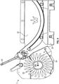
- the spreader tool T comprises a spreader roller 50, having an axis of rotational symmetry R" about which the spreader roller 50 is arranged to rotate, the spreader roller 50 having radially extending tines 52 at intervals spirally therealong, wherein the tines cooperate in use to spread feed from a bale, and further comprising a drive motor 35 arranged to rotate the spreader roller 50.
- the spreader roller 50 is located above a portion of the chassis 20 including an under shield 54.
- the tines 52 are swept back in order to urge the forage from the bale to drop off, be released from the tines and directed towards the under shield 54.
- the rotation of the feed out roller is clockwise (CW) and the rotation of the spreader roller 50 is counter clockwise (CCW) so as to create the maximum throw of the forage from the spreader with the minimum opportunity for clogging and residency time of the forage at the spreader tool T and in the feed out region.
- connection and latching portion are arranged to provide a rising feature such that the spreader roller tines 52 are urged into engagement and into a predetermined alignment before the latch mechanism is latched in.
- the rollers 26 and 50 must be driven by a suitably powered drive means to ensure that the hay can be removed or loosened by the teeth on the chain conveyor, by the roller 26 and by the spreader roller 50 and thus feed out from the bale, without tangling a supply of hay from the bale to deliver loose hay to a line of stock formed.
- the motor 34 mounted on the frame 22 and motor 35 are arranged to be automatically engaged by the transmission means associated with the rollers.
- the transmission has dog clutch and a coupling with the drive shaft that engage with a coupling drive engagement on the hydraulic motors.
- the dog clutch comprises a central locking engagement pin and a cone.
- FIG. 5 the latch mechanism between the support frame 22 and the chassis 20 will now be described.
- the latch L hook and bar are shown in unlatched in Figure 5 , for example when the chassis is located on the ground, and in a latched position with the hook and bar connected in Figure 6 .
- the latch is operated via a bolt 80 and pivot pin 82.
- a torsion spring (not shown) is held at screw points 84, 86 and the chassis 20 further includes a foot portion 70.
- the foot portion 70 acts via the spring 71 and sprung element 72 to hold the bar and latch out of engagement when the chassis supported on the ground and then to release and urge the hook into latch engagement once the headstock and support frame are engaged via the prongs 28 an engagement cone 64.
- the spring 71 in effect takes the pressure of the latch hook when it is disengaged from the bar and urges and maintains the latch while the weight and load of the chassis and bale is with the support frame.
- the apparatus provides a degree of shock absorbency, so as to prevent damage to the component parts of the apparatus and/or the tool T from rough handling and rough landing or positioning on rough or uneven ground.
- the chassis 20 is supported on a stable base and a bale loaded therein preferably using the prongs or forks 28 on the frame 22.
- the prongs are engaged with the chassis 20 and the chassis lifted into position so that the roller transmission for rollers 26 and 50 couples with the motors 34 for the rollers.
- a pressure sensitive control could be used to automatically regulate the appropriate positioning of this cradle to ensure that the bale is retained in the correct position relative to the feed out roller 26 and spreader roller 50.
- the unit is robust simple in operation and versatile.
- the cradle 30 illustrated is particularly adapted for a round bale but a modified cradle or a cradle with adjusting components could be set up so that either a round or a rectangular or square bale could be used in the apparatus.
- the tines 52 on the spreader roller 50 may be altered or adapted in shape for particular spreading functions.
- the feed out roller or rollers could be provided at either side or orientation on the cradle.
- the apparatus is particularly designed for the feed out mechanism as illustrated using the inter-engaging teeth on two associated rollers.
- the arrangement of the cradle and chassis could be used in association with other feed out means.
- the cradle and chassis could be used in association with other feed out means.
- there are significant advantages in providing a unit which can allow separation from the cradle and its supporting chassis from the mounting frame it will also be feasible to provide a unit where the cradle was permanently located in association with the vehicle.
- a detachable tool T or this can be permanently attached to the apparatus.
Landscapes
- Life Sciences & Earth Sciences (AREA)
- Environmental Sciences (AREA)
- Agricultural Machines (AREA)
- Storage Of Harvested Produce (AREA)
- Threshing Machine Elements (AREA)
Claims (9)
- Eine Futterballenausgabevorrichtung (10), beinhaltend:ein Chassis (20), das eingerichtet ist, um in Verwendung betriebsbereit an einem Fahrzeug befestigt oder mit diesem in Verbindung zu sein;ein Ausgabemittel, beinhaltend eine Ausgaberolle (26), die eine Drehsymmetrieachse (R') aufweist, um die sich zu drehen die Ausgaberolle (26) eingerichtet ist, einen Antriebsmotor (34), der eingerichtet ist, um die Ausgaberolle (26) zu drehen, ein Fördermittel (42) zum Treiben eines Ballens zu der Ausgaberolle (26), während sich die Größe eines Ballens verringert; wobei sich die Ausgaberolle (26) an einem Ausgabebereich (40) befindet, und wobei das Fördermittel (42) so ausgerichtet ist, dass das nahe dem Ausgabebereich (40) gelegene Ende des Fördermittels (42) zu der Drehsymmetrieachse (R') der Ausgaberolle (26) hin angehoben ist, ferner beinhaltend ein Verteilerwerkzeug (T), das angepasst ist, um die Futterballenteile, die von der Ausgaberolle (26) an dem Ausgabebereich (40) ausgegeben werden, zu verteilen und zu verbreiten, wobei das Verteilerwerkzeug (T) eine Verteilerrolle (50) beinhaltet, die eine Drehsymmetrieachse (R") aufweist, um die sich zu drehen die Verteilerrolle (50) eingerichtet ist, wobei die Verteilerrolle (50) in Abständen sich radial erstreckende Zinken (52) aufweist, wobei die Zinken (52) bei Verwendung kooperieren, um Futtermittel von einem Ballen zu verteilen, und ferner beinhaltend einen Verteilerantriebsmotor (34), der eingerichtet ist, um die Verteilerrolle (50) zu drehen, und wobei die Ausgaberolle (26) und die Verteilerrolle (50) parallel sind und in entgegengesetzte Richtungen angetrieben werden, wobeidas Fördermittel (42) ein Kettenförderer ist, wobei der Kettenförderer entlang einem Hauptteil seiner Länge im Wesentlichen flach ist, unddadurch gekennzeichnet, dassder Kettenförderer eingerichtet ist, um von einem niedrigsten Punkt des Förderers zu einem höchsten Punkt anzuheben, wobei sich der höchste Punkt über dem im Wesentlichen flachen Teil des Förderers befindet, sich über der Stelle der Drehsymmetrieachsen der Ausgaberolle (R') und der Verteilerrolle (R") befindet und nahe dem Ausgabebereich (40) liegt.
- Futterballenausgabevorrichtung (10) gemäß Anspruch 1, wobei das Fördermittel (42) daran entlang in Abständen sich nach außen erstreckende Zähne umfasst, wobei die Zähne bei Verwendung kooperieren, um Futtermittel aus einem Ballen zu ziehen.
- Futterballenausgabevorrichtung (10) gemäß einem vorhergehenden Anspruch, wobei das Chassis (20) einen unteren Teilabschnitt mit eingreifenden Teilen zum Ermöglichen einer Kopplung mit einem Fahrzeug umfasst.
- Futterballenausgabevorrichtung (10) gemäß einem vorhergehenden Anspruch, wobei das Chassis (20) einen Hilfsrahmen, auf dem die Ausgaberolle befestigt ist, und eine untere Abschirmung (54) umfasst.
- Futterballenausgabevorrichtung (10) gemäß einem vorhergehenden Anspruch, wobei das Chassis (20) einen hinteren Rahmen (32) zum Einschränken von Rückwärtsbewegung eines Futterballens umfasst.
- Futterballenausgabevorrichtung (10) gemäß einem vorhergehenden Anspruch, wobei das Fördermittel (42) zum Treiben eines Ballens innerhalb eines Halters (30) befestigt ist, der auf dem Chassis (20) befestigt ist.
- Futterballenausgabevorrichtung (10) gemäß einem vorhergehenden Anspruch, wobei das Antriebsgetriebe eine Klauenkupplung umfasst.
- Futterballenausgabevorrichtung (10) gemäß einem vorhergehenden Anspruch, wobei das Chassis (20) ferner einen Fußteil (70) beinhaltet.
- Futterballenausgabevorrichtung gemäß Anspruch 8, wobei der Fußteil (70) eine Feder (71) umfasst, die einen Grad an Stoßabsorptionsfähigkeit bereitstellt, um Schaden an den Komponententeilen der Vorrichtung (10) und/oder des Verteilerwerkzeugs (T) infolge von grober Handhabung auf den Boden zu verhindern.
Applications Claiming Priority (2)
| Application Number | Priority Date | Filing Date | Title |
|---|---|---|---|
| GB1622059.2A GB2558243B (en) | 2016-12-22 | 2016-12-22 | Bale feed out apparatus |
| PCT/GB2017/053830 WO2018115862A1 (en) | 2016-12-22 | 2017-12-20 | Bale feed out apparatus |
Publications (2)
| Publication Number | Publication Date |
|---|---|
| EP3557971A1 EP3557971A1 (de) | 2019-10-30 |
| EP3557971B1 true EP3557971B1 (de) | 2022-02-09 |
Family
ID=58360748
Family Applications (1)
| Application Number | Title | Priority Date | Filing Date |
|---|---|---|---|
| EP17822742.7A Active EP3557971B1 (de) | 2016-12-22 | 2017-12-20 | Ballenausgabevorrichtung |
Country Status (4)
| Country | Link |
|---|---|
| US (1) | US11503772B2 (de) |
| EP (1) | EP3557971B1 (de) |
| GB (1) | GB2558243B (de) |
| WO (1) | WO2018115862A1 (de) |
Families Citing this family (2)
| Publication number | Priority date | Publication date | Assignee | Title |
|---|---|---|---|---|
| AU2017343921B2 (en) * | 2016-10-14 | 2023-11-23 | Hustler Equipment Limited | A retention mechanism for agricultural machinery |
| GB201812674D0 (en) * | 2018-08-03 | 2018-09-19 | Spread A Bale Ltd | Bale handling apparatus |
Citations (3)
| Publication number | Priority date | Publication date | Assignee | Title |
|---|---|---|---|---|
| US4195958A (en) | 1978-05-30 | 1980-04-01 | Wayne Diekemper | Bale unroller |
| GB2048211A (en) | 1979-04-23 | 1980-12-10 | Scorgie W E | Apparatus for Handling Straw and the Like Bales |
| NZ286932A (en) | 1996-07-03 | 1998-09-24 | Currie Russell Henry | Hay bale feed out apparatus includes two or more rollers having teeth and means to urge a bale towards the rollers |
Family Cites Families (16)
| Publication number | Priority date | Publication date | Assignee | Title |
|---|---|---|---|---|
| US3552463A (en) * | 1968-11-25 | 1971-01-05 | Koehring Co | Ear corn adapter for forage harvesters |
| DE2715269A1 (de) * | 1977-04-05 | 1978-10-19 | Bayerische Landesanstalt Fuer | Vorrichtung zum aufloesen von grossballen |
| US4266899A (en) * | 1979-04-30 | 1981-05-12 | Skeem Wayne B | Round bale feeder |
| US4443146A (en) * | 1980-08-01 | 1984-04-17 | Duncan Andrew R | Bale feeding apparatus |
| DE3337390C1 (de) * | 1983-10-14 | 1985-05-02 | Hermann 4472 Haren Bergmann | Vorrichtung zum Transportieren und Zerkleinern von Rundballen |
| FR2561490B1 (fr) * | 1984-03-20 | 1986-12-26 | Lenoir Francois | Machine destinee a distribuer et eparpiller le foin, la paille ou produit analogue, a partir de balles cylindriques |
| NZ207957A (en) * | 1984-04-26 | 1987-03-06 | Kennedy Farm Equip | Feedout apparatus for round hay bales;teasing roll loosens wound-up material |
| US4778322A (en) * | 1985-08-22 | 1988-10-18 | Bill Stronski | Round bale retriever/feeder |
| CA2142116A1 (en) | 1992-08-10 | 1994-02-17 | Mervyn William Williams | Agricultural machine |
| FR2759537A1 (fr) * | 1997-02-20 | 1998-08-21 | Suire | Machine agricole de deroulage de balles rondes |
| US5865589A (en) * | 1997-05-07 | 1999-02-02 | Fleischer Manufacturing, Inc. | Bale feeder |
| US7341415B2 (en) * | 2004-04-01 | 2008-03-11 | Sam Roosma | Bale processing apparatus |
| US20060175445A1 (en) * | 2005-02-09 | 2006-08-10 | Duratech Industries | Self-propelled hydrostatic drive bale shredder for large bales |
| US7651043B2 (en) * | 2005-12-15 | 2010-01-26 | DuraTech Industries Internatioal, Inc. | Bale grinder |
| CN104093301B (zh) * | 2012-01-27 | 2016-12-14 | 维米尔制造公司 | 用于各种形状草捆的草捆处理机 |
| US9642312B2 (en) * | 2013-09-11 | 2017-05-09 | Vermeer Manufacturing Company | Bale processor |
-
2016
- 2016-12-22 GB GB1622059.2A patent/GB2558243B/en active Active
-
2017
- 2017-12-20 US US16/472,806 patent/US11503772B2/en active Active
- 2017-12-20 EP EP17822742.7A patent/EP3557971B1/de active Active
- 2017-12-20 WO PCT/GB2017/053830 patent/WO2018115862A1/en not_active Ceased
Patent Citations (3)
| Publication number | Priority date | Publication date | Assignee | Title |
|---|---|---|---|---|
| US4195958A (en) | 1978-05-30 | 1980-04-01 | Wayne Diekemper | Bale unroller |
| GB2048211A (en) | 1979-04-23 | 1980-12-10 | Scorgie W E | Apparatus for Handling Straw and the Like Bales |
| NZ286932A (en) | 1996-07-03 | 1998-09-24 | Currie Russell Henry | Hay bale feed out apparatus includes two or more rollers having teeth and means to urge a bale towards the rollers |
Non-Patent Citations (2)
| Title |
|---|
| ANONYMOUS: "Hustler SL360X bale feeder review", 24 February 2016 (2016-02-24), pages 1 - 3, XP055981996, Retrieved from the Internet <URL:https://www.farmtrader.co.nz/reviews/1602/hustler-sl360x-bale-feeder-review> [retrieved on 20221116] |
| ANONYMOUS: "Martin Pears Engineering | Wessex BFR-180 Round Bale Feeder", 16 November 2022 (2022-11-16), pages 1 - 5, XP055982003, Retrieved from the Internet <URL:https://www.mpearsengineering.co.uk/products/wessex-bfr-180-round-bale-feeder/> [retrieved on 20221116] |
Also Published As
| Publication number | Publication date |
|---|---|
| GB2558243A (en) | 2018-07-11 |
| GB2558243A8 (en) | 2018-08-15 |
| GB2558243B (en) | 2022-06-08 |
| US20200084973A1 (en) | 2020-03-19 |
| WO2018115862A1 (en) | 2018-06-28 |
| US11503772B2 (en) | 2022-11-22 |
| CA3047898A1 (en) | 2018-06-28 |
| EP3557971A1 (de) | 2019-10-30 |
| GB201622059D0 (en) | 2017-02-08 |
Similar Documents
| Publication | Publication Date | Title |
|---|---|---|
| US5340040A (en) | Disintegration of baled crop materials | |
| US6886763B2 (en) | Bale processor | |
| US4088272A (en) | Bale loader and shredder | |
| US5865589A (en) | Bale feeder | |
| CA2488298C (en) | Bale processor with grain mixing attachment | |
| CA1277960C (en) | Round haybale unloader | |
| US11503772B2 (en) | Bale feed out apparatus | |
| EP3033938B1 (de) | Strohabwickel- und -verteilungsvorrichtung | |
| US4084708A (en) | Bale lifter and carrier attachment | |
| CA2291319C (en) | Square bale processor | |
| US7717660B1 (en) | Device and method for lifting and transporting conventional hay bale feeders with a round hay bale | |
| CA3047898C (en) | Bale feed out apparatus | |
| EP3045028B1 (de) | Trichter und sein halter | |
| US5067870A (en) | Hay bale unroller | |
| US10682940B2 (en) | Agricultural dump cart | |
| US2909264A (en) | Bale loading machine | |
| RU2726425C1 (ru) | Погрузчик тюков сена и соломы Бруславцева В.Е. | |
| US20110064542A1 (en) | Tiltable roller bed trailer | |
| CA1038338A (en) | Vehicle for distributing straw or like material from round bales | |
| DE202009004934U1 (de) | Einstreugerät zum Aufnehmen, Transportieren, Auflösen und Auswerfen von Streugut | |
| CA2487635C (en) | Bale processor | |
| JP4368516B2 (ja) | 堆肥散布機 | |
| US7588203B2 (en) | Silage pile defacer | |
| CA2285896C (en) | Square bale loading platform and processing apparatus | |
| CA2171146A1 (en) | Bale feeder |
Legal Events
| Date | Code | Title | Description |
|---|---|---|---|
| STAA | Information on the status of an ep patent application or granted ep patent |
Free format text: STATUS: UNKNOWN |
|
| STAA | Information on the status of an ep patent application or granted ep patent |
Free format text: STATUS: THE INTERNATIONAL PUBLICATION HAS BEEN MADE |
|
| PUAI | Public reference made under article 153(3) epc to a published international application that has entered the european phase |
Free format text: ORIGINAL CODE: 0009012 |
|
| STAA | Information on the status of an ep patent application or granted ep patent |
Free format text: STATUS: REQUEST FOR EXAMINATION WAS MADE |
|
| 17P | Request for examination filed |
Effective date: 20190619 |
|
| AK | Designated contracting states |
Kind code of ref document: A1 Designated state(s): AL AT BE BG CH CY CZ DE DK EE ES FI FR GB GR HR HU IE IS IT LI LT LU LV MC MK MT NL NO PL PT RO RS SE SI SK SM TR |
|
| AX | Request for extension of the european patent |
Extension state: BA ME |
|
| DAV | Request for validation of the european patent (deleted) | ||
| DAX | Request for extension of the european patent (deleted) | ||
| STAA | Information on the status of an ep patent application or granted ep patent |
Free format text: STATUS: EXAMINATION IS IN PROGRESS |
|
| 17Q | First examination report despatched |
Effective date: 20200922 |
|
| GRAP | Despatch of communication of intention to grant a patent |
Free format text: ORIGINAL CODE: EPIDOSNIGR1 |
|
| STAA | Information on the status of an ep patent application or granted ep patent |
Free format text: STATUS: GRANT OF PATENT IS INTENDED |
|
| INTG | Intention to grant announced |
Effective date: 20210813 |
|
| GRAS | Grant fee paid |
Free format text: ORIGINAL CODE: EPIDOSNIGR3 |
|
| TPAC | Observations filed by third parties |
Free format text: ORIGINAL CODE: EPIDOSNTIPA |
|
| GRAA | (expected) grant |
Free format text: ORIGINAL CODE: 0009210 |
|
| STAA | Information on the status of an ep patent application or granted ep patent |
Free format text: STATUS: THE PATENT HAS BEEN GRANTED |
|
| AK | Designated contracting states |
Kind code of ref document: B1 Designated state(s): AL AT BE BG CH CY CZ DE DK EE ES FI FR GB GR HR HU IE IS IT LI LT LU LV MC MK MT NL NO PL PT RO RS SE SI SK SM TR |
|
| REG | Reference to a national code |
Ref country code: GB Ref legal event code: FG4D |
|
| REG | Reference to a national code |
Ref country code: CH Ref legal event code: EP Ref country code: AT Ref legal event code: REF Ref document number: 1466936 Country of ref document: AT Kind code of ref document: T Effective date: 20220215 |
|
| REG | Reference to a national code |
Ref country code: DE Ref legal event code: R096 Ref document number: 602017053232 Country of ref document: DE |
|
| REG | Reference to a national code |
Ref country code: IE Ref legal event code: FG4D |
|
| REG | Reference to a national code |
Ref country code: LT Ref legal event code: MG9D |
|
| REG | Reference to a national code |
Ref country code: NL Ref legal event code: MP Effective date: 20220209 |
|
| REG | Reference to a national code |
Ref country code: AT Ref legal event code: MK05 Ref document number: 1466936 Country of ref document: AT Kind code of ref document: T Effective date: 20220209 |
|
| PG25 | Lapsed in a contracting state [announced via postgrant information from national office to epo] |
Ref country code: SE Free format text: LAPSE BECAUSE OF FAILURE TO SUBMIT A TRANSLATION OF THE DESCRIPTION OR TO PAY THE FEE WITHIN THE PRESCRIBED TIME-LIMIT Effective date: 20220209 Ref country code: RS Free format text: LAPSE BECAUSE OF FAILURE TO SUBMIT A TRANSLATION OF THE DESCRIPTION OR TO PAY THE FEE WITHIN THE PRESCRIBED TIME-LIMIT Effective date: 20220209 Ref country code: PT Free format text: LAPSE BECAUSE OF FAILURE TO SUBMIT A TRANSLATION OF THE DESCRIPTION OR TO PAY THE FEE WITHIN THE PRESCRIBED TIME-LIMIT Effective date: 20220609 Ref country code: NO Free format text: LAPSE BECAUSE OF FAILURE TO SUBMIT A TRANSLATION OF THE DESCRIPTION OR TO PAY THE FEE WITHIN THE PRESCRIBED TIME-LIMIT Effective date: 20220509 Ref country code: NL Free format text: LAPSE BECAUSE OF FAILURE TO SUBMIT A TRANSLATION OF THE DESCRIPTION OR TO PAY THE FEE WITHIN THE PRESCRIBED TIME-LIMIT Effective date: 20220209 Ref country code: LT Free format text: LAPSE BECAUSE OF FAILURE TO SUBMIT A TRANSLATION OF THE DESCRIPTION OR TO PAY THE FEE WITHIN THE PRESCRIBED TIME-LIMIT Effective date: 20220209 Ref country code: HR Free format text: LAPSE BECAUSE OF FAILURE TO SUBMIT A TRANSLATION OF THE DESCRIPTION OR TO PAY THE FEE WITHIN THE PRESCRIBED TIME-LIMIT Effective date: 20220209 Ref country code: ES Free format text: LAPSE BECAUSE OF FAILURE TO SUBMIT A TRANSLATION OF THE DESCRIPTION OR TO PAY THE FEE WITHIN THE PRESCRIBED TIME-LIMIT Effective date: 20220209 Ref country code: BG Free format text: LAPSE BECAUSE OF FAILURE TO SUBMIT A TRANSLATION OF THE DESCRIPTION OR TO PAY THE FEE WITHIN THE PRESCRIBED TIME-LIMIT Effective date: 20220509 |
|
| PG25 | Lapsed in a contracting state [announced via postgrant information from national office to epo] |
Ref country code: PL Free format text: LAPSE BECAUSE OF FAILURE TO SUBMIT A TRANSLATION OF THE DESCRIPTION OR TO PAY THE FEE WITHIN THE PRESCRIBED TIME-LIMIT Effective date: 20220209 Ref country code: LV Free format text: LAPSE BECAUSE OF FAILURE TO SUBMIT A TRANSLATION OF THE DESCRIPTION OR TO PAY THE FEE WITHIN THE PRESCRIBED TIME-LIMIT Effective date: 20220209 Ref country code: GR Free format text: LAPSE BECAUSE OF FAILURE TO SUBMIT A TRANSLATION OF THE DESCRIPTION OR TO PAY THE FEE WITHIN THE PRESCRIBED TIME-LIMIT Effective date: 20220510 Ref country code: FI Free format text: LAPSE BECAUSE OF FAILURE TO SUBMIT A TRANSLATION OF THE DESCRIPTION OR TO PAY THE FEE WITHIN THE PRESCRIBED TIME-LIMIT Effective date: 20220209 Ref country code: AT Free format text: LAPSE BECAUSE OF FAILURE TO SUBMIT A TRANSLATION OF THE DESCRIPTION OR TO PAY THE FEE WITHIN THE PRESCRIBED TIME-LIMIT Effective date: 20220209 |
|
| PG25 | Lapsed in a contracting state [announced via postgrant information from national office to epo] |
Ref country code: IS Free format text: LAPSE BECAUSE OF FAILURE TO SUBMIT A TRANSLATION OF THE DESCRIPTION OR TO PAY THE FEE WITHIN THE PRESCRIBED TIME-LIMIT Effective date: 20220609 |
|
| PG25 | Lapsed in a contracting state [announced via postgrant information from national office to epo] |
Ref country code: SM Free format text: LAPSE BECAUSE OF FAILURE TO SUBMIT A TRANSLATION OF THE DESCRIPTION OR TO PAY THE FEE WITHIN THE PRESCRIBED TIME-LIMIT Effective date: 20220209 Ref country code: SK Free format text: LAPSE BECAUSE OF FAILURE TO SUBMIT A TRANSLATION OF THE DESCRIPTION OR TO PAY THE FEE WITHIN THE PRESCRIBED TIME-LIMIT Effective date: 20220209 Ref country code: RO Free format text: LAPSE BECAUSE OF FAILURE TO SUBMIT A TRANSLATION OF THE DESCRIPTION OR TO PAY THE FEE WITHIN THE PRESCRIBED TIME-LIMIT Effective date: 20220209 Ref country code: EE Free format text: LAPSE BECAUSE OF FAILURE TO SUBMIT A TRANSLATION OF THE DESCRIPTION OR TO PAY THE FEE WITHIN THE PRESCRIBED TIME-LIMIT Effective date: 20220209 Ref country code: DK Free format text: LAPSE BECAUSE OF FAILURE TO SUBMIT A TRANSLATION OF THE DESCRIPTION OR TO PAY THE FEE WITHIN THE PRESCRIBED TIME-LIMIT Effective date: 20220209 Ref country code: CZ Free format text: LAPSE BECAUSE OF FAILURE TO SUBMIT A TRANSLATION OF THE DESCRIPTION OR TO PAY THE FEE WITHIN THE PRESCRIBED TIME-LIMIT Effective date: 20220209 |
|
| REG | Reference to a national code |
Ref country code: DE Ref legal event code: R026 Ref document number: 602017053232 Country of ref document: DE |
|
| PLBI | Opposition filed |
Free format text: ORIGINAL CODE: 0009260 |
|
| PLAB | Opposition data, opponent's data or that of the opponent's representative modified |
Free format text: ORIGINAL CODE: 0009299OPPO |
|
| PLAX | Notice of opposition and request to file observation + time limit sent |
Free format text: ORIGINAL CODE: EPIDOSNOBS2 |
|
| PG25 | Lapsed in a contracting state [announced via postgrant information from national office to epo] |
Ref country code: AL Free format text: LAPSE BECAUSE OF FAILURE TO SUBMIT A TRANSLATION OF THE DESCRIPTION OR TO PAY THE FEE WITHIN THE PRESCRIBED TIME-LIMIT Effective date: 20220209 |
|
| 26 | Opposition filed |
Opponent name: HUSTLER EQUIPMENT LIMITED Effective date: 20221108 |
|
| R26 | Opposition filed (corrected) |
Opponent name: HUSTLER EQUIPMENT LIMITED Effective date: 20221108 |
|
| PG25 | Lapsed in a contracting state [announced via postgrant information from national office to epo] |
Ref country code: SI Free format text: LAPSE BECAUSE OF FAILURE TO SUBMIT A TRANSLATION OF THE DESCRIPTION OR TO PAY THE FEE WITHIN THE PRESCRIBED TIME-LIMIT Effective date: 20220209 |
|
| PLBB | Reply of patent proprietor to notice(s) of opposition received |
Free format text: ORIGINAL CODE: EPIDOSNOBS3 |
|
| PG25 | Lapsed in a contracting state [announced via postgrant information from national office to epo] |
Ref country code: IT Free format text: LAPSE BECAUSE OF FAILURE TO SUBMIT A TRANSLATION OF THE DESCRIPTION OR TO PAY THE FEE WITHIN THE PRESCRIBED TIME-LIMIT Effective date: 20220209 |
|
| REG | Reference to a national code |
Ref country code: CH Ref legal event code: PL |
|
| REG | Reference to a national code |
Ref country code: BE Ref legal event code: MM Effective date: 20221231 |
|
| PG25 | Lapsed in a contracting state [announced via postgrant information from national office to epo] |
Ref country code: LU Free format text: LAPSE BECAUSE OF NON-PAYMENT OF DUE FEES Effective date: 20221220 |
|
| PG25 | Lapsed in a contracting state [announced via postgrant information from national office to epo] |
Ref country code: LI Free format text: LAPSE BECAUSE OF NON-PAYMENT OF DUE FEES Effective date: 20221231 Ref country code: CH Free format text: LAPSE BECAUSE OF NON-PAYMENT OF DUE FEES Effective date: 20221231 |
|
| PG25 | Lapsed in a contracting state [announced via postgrant information from national office to epo] |
Ref country code: BE Free format text: LAPSE BECAUSE OF NON-PAYMENT OF DUE FEES Effective date: 20221231 |
|
| PLAB | Opposition data, opponent's data or that of the opponent's representative modified |
Free format text: ORIGINAL CODE: 0009299OPPO |
|
| R26 | Opposition filed (corrected) |
Opponent name: HUSTLER EQUIPMENT LIMITED Effective date: 20221108 |
|
| PG25 | Lapsed in a contracting state [announced via postgrant information from national office to epo] |
Ref country code: HU Free format text: LAPSE BECAUSE OF FAILURE TO SUBMIT A TRANSLATION OF THE DESCRIPTION OR TO PAY THE FEE WITHIN THE PRESCRIBED TIME-LIMIT; INVALID AB INITIO Effective date: 20171220 |
|
| PG25 | Lapsed in a contracting state [announced via postgrant information from national office to epo] |
Ref country code: CY Free format text: LAPSE BECAUSE OF FAILURE TO SUBMIT A TRANSLATION OF THE DESCRIPTION OR TO PAY THE FEE WITHIN THE PRESCRIBED TIME-LIMIT Effective date: 20220209 |
|
| PG25 | Lapsed in a contracting state [announced via postgrant information from national office to epo] |
Ref country code: MK Free format text: LAPSE BECAUSE OF FAILURE TO SUBMIT A TRANSLATION OF THE DESCRIPTION OR TO PAY THE FEE WITHIN THE PRESCRIBED TIME-LIMIT Effective date: 20220209 |
|
| PG25 | Lapsed in a contracting state [announced via postgrant information from national office to epo] |
Ref country code: MC Free format text: LAPSE BECAUSE OF FAILURE TO SUBMIT A TRANSLATION OF THE DESCRIPTION OR TO PAY THE FEE WITHIN THE PRESCRIBED TIME-LIMIT Effective date: 20220209 |
|
| PG25 | Lapsed in a contracting state [announced via postgrant information from national office to epo] |
Ref country code: TR Free format text: LAPSE BECAUSE OF FAILURE TO SUBMIT A TRANSLATION OF THE DESCRIPTION OR TO PAY THE FEE WITHIN THE PRESCRIBED TIME-LIMIT Effective date: 20220209 Ref country code: MC Free format text: LAPSE BECAUSE OF FAILURE TO SUBMIT A TRANSLATION OF THE DESCRIPTION OR TO PAY THE FEE WITHIN THE PRESCRIBED TIME-LIMIT Effective date: 20220209 |
|
| REG | Reference to a national code |
Ref country code: DE Ref legal event code: R100 Ref document number: 602017053232 Country of ref document: DE |
|
| PG25 | Lapsed in a contracting state [announced via postgrant information from national office to epo] |
Ref country code: MT Free format text: LAPSE BECAUSE OF FAILURE TO SUBMIT A TRANSLATION OF THE DESCRIPTION OR TO PAY THE FEE WITHIN THE PRESCRIBED TIME-LIMIT Effective date: 20220209 |
|
| PLCK | Communication despatched that opposition was rejected |
Free format text: ORIGINAL CODE: EPIDOSNREJ1 |
|
| PLBN | Opposition rejected |
Free format text: ORIGINAL CODE: 0009273 |
|
| STAA | Information on the status of an ep patent application or granted ep patent |
Free format text: STATUS: OPPOSITION REJECTED |
|
| 27O | Opposition rejected |
Effective date: 20240912 |
|
| PGFP | Annual fee paid to national office [announced via postgrant information from national office to epo] |
Ref country code: GB Payment date: 20251230 Year of fee payment: 9 |
|
| PGFP | Annual fee paid to national office [announced via postgrant information from national office to epo] |
Ref country code: FR Payment date: 20251229 Year of fee payment: 9 |
|
| PGFP | Annual fee paid to national office [announced via postgrant information from national office to epo] |
Ref country code: IE Payment date: 20251229 Year of fee payment: 9 |
|
| PGFP | Annual fee paid to national office [announced via postgrant information from national office to epo] |
Ref country code: DE Payment date: 20251230 Year of fee payment: 9 |