EP3557718A1 - Dispositif d'alimentation électrique et son procédé de fonctionnement - Google Patents
Dispositif d'alimentation électrique et son procédé de fonctionnement Download PDFInfo
- Publication number
- EP3557718A1 EP3557718A1 EP19168168.3A EP19168168A EP3557718A1 EP 3557718 A1 EP3557718 A1 EP 3557718A1 EP 19168168 A EP19168168 A EP 19168168A EP 3557718 A1 EP3557718 A1 EP 3557718A1
- Authority
- EP
- European Patent Office
- Prior art keywords
- port
- convertor
- electrical power
- voltage threshold
- power supply
- Prior art date
- Legal status (The legal status is an assumption and is not a legal conclusion. Google has not performed a legal analysis and makes no representation as to the accuracy of the status listed.)
- Granted
Links
Images
Classifications
-
- G—PHYSICS
- G06—COMPUTING OR CALCULATING; COUNTING
- G06F—ELECTRIC DIGITAL DATA PROCESSING
- G06F1/00—Details not covered by groups G06F3/00 - G06F13/00 and G06F21/00
- G06F1/26—Power supply means, e.g. regulation thereof
- G06F1/266—Arrangements to supply power to external peripherals either directly from the computer or under computer control, e.g. supply of power through the communication port, computer controlled power-strips
-
- H—ELECTRICITY
- H02—GENERATION; CONVERSION OR DISTRIBUTION OF ELECTRIC POWER
- H02J—ELECTRIC POWER NETWORKS; CIRCUIT ARRANGEMENTS OR SYSTEMS FOR SUPPLYING OR DISTRIBUTING ELECTRIC POWER; SYSTEMS FOR STORING ELECTRIC ENERGY
- H02J7/00—Circuit arrangements for charging or discharging batteries or for supplying loads from batteries
- H02J7/70—Circuit arrangements for charging or discharging batteries or for supplying loads from batteries characterised by the mechanical construction
-
- G—PHYSICS
- G06—COMPUTING OR CALCULATING; COUNTING
- G06F—ELECTRIC DIGITAL DATA PROCESSING
- G06F13/00—Interconnection of, or transfer of information or other signals between, memories, input/output devices or central processing units
- G06F13/38—Information transfer, e.g. on bus
- G06F13/40—Bus structure
- G06F13/4063—Device-to-bus coupling
- G06F13/4068—Electrical coupling
- G06F13/4081—Live connection to bus, e.g. hot-plugging
-
- H—ELECTRICITY
- H02—GENERATION; CONVERSION OR DISTRIBUTION OF ELECTRIC POWER
- H02J—ELECTRIC POWER NETWORKS; CIRCUIT ARRANGEMENTS OR SYSTEMS FOR SUPPLYING OR DISTRIBUTING ELECTRIC POWER; SYSTEMS FOR STORING ELECTRIC ENERGY
- H02J7/00—Circuit arrangements for charging or discharging batteries or for supplying loads from batteries
- H02J7/50—Circuit arrangements for charging or discharging batteries or for supplying loads from batteries acting upon multiple batteries simultaneously or sequentially
-
- H—ELECTRICITY
- H02—GENERATION; CONVERSION OR DISTRIBUTION OF ELECTRIC POWER
- H02J—ELECTRIC POWER NETWORKS; CIRCUIT ARRANGEMENTS OR SYSTEMS FOR SUPPLYING OR DISTRIBUTING ELECTRIC POWER; SYSTEMS FOR STORING ELECTRIC ENERGY
- H02J7/00—Circuit arrangements for charging or discharging batteries or for supplying loads from batteries
- H02J7/855—Circuit arrangements for charging or discharging batteries or for supplying loads from batteries with circuits adapted for supplying loads from the battery
-
- H—ELECTRICITY
- H02—GENERATION; CONVERSION OR DISTRIBUTION OF ELECTRIC POWER
- H02J—ELECTRIC POWER NETWORKS; CIRCUIT ARRANGEMENTS OR SYSTEMS FOR SUPPLYING OR DISTRIBUTING ELECTRIC POWER; SYSTEMS FOR STORING ELECTRIC ENERGY
- H02J7/00—Circuit arrangements for charging or discharging batteries or for supplying loads from batteries
- H02J7/90—Regulation of charging or discharging current or voltage
- H02J7/933—Regulation of charging or discharging current or voltage the cycle being controlled or terminated in response to electric parameters
-
- H—ELECTRICITY
- H02—GENERATION; CONVERSION OR DISTRIBUTION OF ELECTRIC POWER
- H02M—APPARATUS FOR CONVERSION BETWEEN AC AND AC, BETWEEN AC AND DC, OR BETWEEN DC AND DC, AND FOR USE WITH MAINS OR SIMILAR POWER SUPPLY SYSTEMS; CONVERSION OF DC OR AC INPUT POWER INTO SURGE OUTPUT POWER; CONTROL OR REGULATION THEREOF
- H02M3/00—Conversion of DC power input into DC power output
- H02M3/02—Conversion of DC power input into DC power output without intermediate conversion into AC
- H02M3/04—Conversion of DC power input into DC power output without intermediate conversion into AC by static converters
- H02M3/10—Conversion of DC power input into DC power output without intermediate conversion into AC by static converters using discharge tubes with control electrode or semiconductor devices with control electrode
- H02M3/145—Conversion of DC power input into DC power output without intermediate conversion into AC by static converters using discharge tubes with control electrode or semiconductor devices with control electrode using devices of a triode or transistor type requiring continuous application of a control signal
- H02M3/155—Conversion of DC power input into DC power output without intermediate conversion into AC by static converters using discharge tubes with control electrode or semiconductor devices with control electrode using devices of a triode or transistor type requiring continuous application of a control signal using semiconductor devices only
- H02M3/156—Conversion of DC power input into DC power output without intermediate conversion into AC by static converters using discharge tubes with control electrode or semiconductor devices with control electrode using devices of a triode or transistor type requiring continuous application of a control signal using semiconductor devices only with automatic control of output voltage or current, e.g. switching regulators
- H02M3/158—Conversion of DC power input into DC power output without intermediate conversion into AC by static converters using discharge tubes with control electrode or semiconductor devices with control electrode using devices of a triode or transistor type requiring continuous application of a control signal using semiconductor devices only with automatic control of output voltage or current, e.g. switching regulators including plural semiconductor devices as final control devices for a single load
- H02M3/1582—Buck-boost converters
-
- G—PHYSICS
- G06—COMPUTING OR CALCULATING; COUNTING
- G06F—ELECTRIC DIGITAL DATA PROCESSING
- G06F2213/00—Indexing scheme relating to interconnection of, or transfer of information or other signals between, memories, input/output devices or central processing units
- G06F2213/0042—Universal serial bus [USB]
-
- H—ELECTRICITY
- H02—GENERATION; CONVERSION OR DISTRIBUTION OF ELECTRIC POWER
- H02J—ELECTRIC POWER NETWORKS; CIRCUIT ARRANGEMENTS OR SYSTEMS FOR SUPPLYING OR DISTRIBUTING ELECTRIC POWER; SYSTEMS FOR STORING ELECTRIC ENERGY
- H02J2105/00—Networks for supplying or distributing electric power characterised by their spatial reach or by the load
- H02J2105/40—Networks for supplying or distributing electric power characterised by their spatial reach or by the load characterised by the loads connecting to the networks or being supplied by the networks
- H02J2105/44—Portable electronic devices
-
- H—ELECTRICITY
- H02—GENERATION; CONVERSION OR DISTRIBUTION OF ELECTRIC POWER
- H02J—ELECTRIC POWER NETWORKS; CIRCUIT ARRANGEMENTS OR SYSTEMS FOR SUPPLYING OR DISTRIBUTING ELECTRIC POWER; SYSTEMS FOR STORING ELECTRIC ENERGY
- H02J2207/00—Details of circuit arrangements for charging or discharging batteries or supplying loads from batteries
- H02J2207/20—Charging or discharging characterised by the power electronics converter
-
- H—ELECTRICITY
- H02—GENERATION; CONVERSION OR DISTRIBUTION OF ELECTRIC POWER
- H02J—ELECTRIC POWER NETWORKS; CIRCUIT ARRANGEMENTS OR SYSTEMS FOR SUPPLYING OR DISTRIBUTING ELECTRIC POWER; SYSTEMS FOR STORING ELECTRIC ENERGY
- H02J7/00—Circuit arrangements for charging or discharging batteries or for supplying loads from batteries
-
- H—ELECTRICITY
- H02—GENERATION; CONVERSION OR DISTRIBUTION OF ELECTRIC POWER
- H02M—APPARATUS FOR CONVERSION BETWEEN AC AND AC, BETWEEN AC AND DC, OR BETWEEN DC AND DC, AND FOR USE WITH MAINS OR SIMILAR POWER SUPPLY SYSTEMS; CONVERSION OF DC OR AC INPUT POWER INTO SURGE OUTPUT POWER; CONTROL OR REGULATION THEREOF
- H02M1/00—Details of apparatus for conversion
- H02M1/0083—Converters characterised by their input or output configuration
- H02M1/009—Converters characterised by their input or output configuration having two or more independently controlled outputs
Definitions
- the invention generally relates to an electrical power supply device and method of operating the electrical power supply device.
- An electrical power supply device includes a DC-DC power convertor receiving an input voltage and producing an output voltage, a first port in electrical communication with the DC-DC power convertor configured to supply electrical power to a first consumer device, and a second port distinct from the first port and in electrical communication with the DC-DC power convertor configured to supply electrical power to a second consumer device.
- the electrical power supply device further includes a device controller in that is communication with the DC-DC power convertor, the first port, and the second port.
- the device controller has one or more processors and memory.
- the memory includes instructions which causes the device controller to command the DC-DC power convertor to produce the output voltage between a first voltage threshold and a second voltage threshold higher than the first voltage threshold in accordance with the first consumer device being connected to the first port and the second consumer device not being connected to the second port.
- the memory further includes instructions which causes the device controller to command the DC-DC power convertor to produce the output voltage at the first voltage threshold in accordance with the first consumer device being connected to the first port and the second consumer device being connected to the second port.
- the DC-DC power convertor has a buck-boost configuration.
- the electrical power supply device may conform to the Universal Serial Bus (USB) Power Delivery Specification 2.0 or the USB Power Delivery Specification 3.0.
- USB Universal Serial Bus
- the first voltage threshold is 5 volts and the second voltage threshold may be 20 or 21 volts.
- the DC-DC power convertor has a first maximum current output capacity of 6 amperes in accordance with the output voltage being equal to or less than the input voltage and the DC-DC power convertor has a second maximum current output capacity of 5 amperes in accordance with the output voltage being greater than the input voltage.
- the DC-DC power convertor has a buck-only configuration and wherein the first voltage threshold is 5 volts and the second voltage threshold is 9 volts.
- the DC-DC power convertor has a maximum current output capacity of 6 amperes.
- a method of operating such an electrical power supply device incldues the steps of:
- USB Universal Serial Bus
- USB has become a ubiquitous power socket for many consumer devices such as cellular telephones, digital media players and/or other hand-held devices.
- Users utilize USB to fulfil their requirements not only in terms of data but also to provide power to, or charge, their devices simply, often without the need to load a driver, in order to carry out "traditional" USB functions.
- USB Power Delivery (PD) Specification enables the maximum functionality of USB by providing more flexible power delivery, e.g. for battery charging, along with data over a single cable. Its aim is to operate with and build on the existing USB ecosystem.
- the USB Power Delivery Specification 2.0 and the USB Power Delivery Specification 3.0 are published by the USB Implementer's Forum, Inc and each is incorporated by reference herein.
- a proposed innovative solution is to provide a single electrical power supply device that is connected to multiple ports which are each configured to connect with a consumer device.
- the electrical power supply device includes a DC-DC power convertor that receives an input voltage, e.g. from the vehicle battery and produces a different output voltage.
- the DC-DC power convertor is connected to each of the ports.
- the electrical power supply device also includes a device controller in communication with the DC-DC power converter, the first port, and the second port.
- the device controller is programmed to command the DC-DC power convertor to produce the output voltage between a first voltage threshold, e.g. 5 volts and a second voltage threshold, e.g.
- the device controller is further programmed to command the DC-DC power convertor to produce the output voltage at the first voltage threshold when multiple consumer devices are connected to multiple ports.
- This innovation provides offer a lower cost "entry level" PD solution for multiple ports since it eliminates the need for a dedicated power supply for each port while still offering PD charging capability on one port at a time.
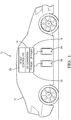
- Fig. 1 illustrates an electrical power supply device, e.g. a Universal Serial Bus (USB) power delivery (PD) device, hereinafter referred to as the PD device 10 that is designed for use in a motor vehicle 12.
- the PD device 10 may be used to support battery charging of USB enabled devices in the vehicle 12 (not shown).
- the PD device 10 includes a buck-only DC-DC power convertor, hereinafter referred to as the DC convertor 14, that receives an input voltage from a vehicle's electrical system.
- the output voltage can by one of at least two different voltages, e.g. a 5 volt output to support a normal USB charge rate or a 9 volt output to support an enhanced USB charge rate.
- the DC convertor 14, being a buck-only DC-DC power convertor is incapable of providing an output voltage that is greater than the input voltage.
- the DC convertor 14 may be a "buck/boost" type that generates an output voltage from 5 volts to 21 volts which is both above and below the typical vehicle input voltage of 12 to 14 volts.
- the DC convertor 14 is connected to at least two USB ports, e.g. USB-C type ports (see USB Type-C Specification 1.0 published by the USB Implementer's Forum), that are configured to connect with and supply electrical power for charging to consumer devices and are hereinafter referred to as first port 16 and second port 18.
- USB-C type ports see USB Type-C Specification 1.0 published by the USB Implementer's Forum
- the PD device 10 also includes a device controller 20 in communication with the DC convertor 14 and the first and second ports 16, 18.
- the device controller 20 has one or more processors and memory.
- the processors may be a microprocessors, application specific integrated circuits (ASIC), or built from discrete logic and timing circuits (not shown).
- Software instructions that program the processors may be stored in a non-volatile (NV) memory device (not shown).
- the NV memory device may be contained within the microprocessor or ASIC or it may be a separate device.
- Non-limiting examples of the types of NV memory that may be used include electrically erasable programmable read only memory (EEPROM), masked read only memory (ROM), and flash memory.
- the memory stores instructions that cause the device controller 20 to communicate with the first and second ports 16, 18 to determine whether a consumer devices is connected to the first and/or second ports 16, 18. If the device controller 20 determines that a consumer device 22 is concerted to only to the first port 16 and no consumer devices are connected to the second port 18 or any other port (not shown), the device controller 20 will communicate with the connected first consumer device 22 thought the first port 16 according to the USB PD protocol to negotiate an output voltage between a first voltage threshold, e.g. 5 volts and a second voltage threshold, e.g. 21 volts and command the DC convertor 14 to provide the output voltage at the negotiated voltage.
- a first voltage threshold e.g. 5 volts
- a second voltage threshold e.g. 21 volts
- the device controller 20 determines that the consumer device 22 is connected to the first port 16 and another consumer device 24 is connected to the second port 18, the device controller 20 will communicate with the connected first and second consumer devices 22, 24 thought the first and second ports 16, 18 according to the USB PD protocol to inform the consumer devices that the output voltage is fixed at the lower first voltage threshold.
- the device controller 20 will confirm that the DC convertor 14 is producing the output voltage at the first voltage threshold before supplying the output voltage to the second port 18.
- the PD device 10 may also include interface circuitry (not shown), such as a controller area network (CAN) transceiver, a local interconnect network (LIN) transceiver, a USB transceiver, and/or an analog/digital convertor circuit to allow the PD device 10 to establish electrical communication with other devices within the vehicle 12.
- interface circuitry such as a controller area network (CAN) transceiver, a local interconnect network (LIN) transceiver, a USB transceiver, and/or an analog/digital convertor circuit to allow the PD device 10 to establish electrical communication with other devices within the vehicle 12.
- the first voltage threshold is 5 volts and the second voltage threshold is 20 volts.
- the first voltage threshold is 5 volts and the second voltage threshold is 21 volts.
- the buck/boost DC convertor 14 has a current output capacity that is limited to 6 amperes when the output voltage is less than or equal to the input voltage.
- the current output capacity of the DC convertor 14 is limited to 5 amperes when the output voltage is greater than the input voltage.
- the PD device 10 may include power switches that are used to limit the current on the first and second ports 16, 18.
- the first voltage threshold is 5 volts and the second voltage threshold is 9 volts.
- the buck-only DC convertor 14 has a current output capacity that is limited to 6 amperes.
- the PD device 10 may include power switches that are used to limit the current on the first and second ports 16, 18.
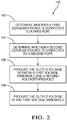
- Fig. 2 illustrates a method 100 of operating the PD device 10 which includes the device controller 20, the DC convertor 14, the first port 16, and the second port 18.
- the device controller 20 has one or more processors and memory.
- the method 100 includes the following steps:
- STEP 102 DETERMINE WHETHER A FIRST CONSUMER DEVICE IS CONNECTED TO A FIRST PORT, includes the PD device 10 determining whether the first consumer device 22 is connected to the first port 16;
- STEP 104 DETERMINE WHETHER A SECOND CONSUMER DEVICE IS CONNECTED TO A SECOND PORT, includes the PD device 10 determining whether the second consumer device 24 is connected to the second port 18;
- STEP 106 PRODUCE THE OUTPUT VOLTAGE BETWEEN A FIRST VOLTAGE THRESHOLD AND A SECOND VOLTAGE THRESHOLD, includes the PD device 10 producing an output voltage that is between a first voltage threshold and a second voltage threshold in accordance with the device controller 20 determining that the first consumer device 22 is connected to the first port 16 and the second consumer device 24 is not connected to the second port 18. This second voltage threshold is higher than the first voltage threshold; and
- STEP 108 PRODUCE THE OUTPUT VOLTAGE AT THE FIRST VOLTAGE THRESHOLD, includes the PD device 10 producing the output voltage at the first voltage threshold via the DC-DC power convertor in accordance with the device controller 20 determining that the first consumer device 22 is connected to the first port 16 and the second consumer device 24 is connected to the second port 18.
- an electrical power supply device e.g. a USB PD device 10
- a method 100 of operating such a PD device 10 is provided.
- the PD device 10 and method 100 provides the benefit of a USB PD device 10 that is capable of supporting multiple ports with a single DC convertor at a lower cost than prior USB PD device designs.
- 'one or more' includes a function being performed by one element, a function being performed by more than one element, e.g., in a distributed fashion, several functions being performed by one element, several functions being performed by several elements, or any combination of the above.
- first, second, etc. are, in some instances, used herein to describe various elements, these elements should not be limited by these terms. These terms are only used to distinguish one element from another.
- a first contact could be termed a second contact, and, similarly, a second contact could be termed a first contact, without departing from the scope of the various described embodiments.
- the first contact and the second contact are both contacts, but they are not the same contact.
- the term “if' is, optionally, construed to mean “when” or “upon” or “in response to determining” or “in response to detecting,” depending on the context.
- the phrase “if it is determined” or “if [a stated condition or event] is detected” is, optionally, construed to mean “upon determining” or “in response to determining” or “upon detecting [the stated condition or event]” or “in response to detecting [the stated condition or event],” depending on the context.
Landscapes
- Engineering & Computer Science (AREA)
- Power Engineering (AREA)
- General Engineering & Computer Science (AREA)
- Theoretical Computer Science (AREA)
- Computer Hardware Design (AREA)
- Physics & Mathematics (AREA)
- General Physics & Mathematics (AREA)
- Dc-Dc Converters (AREA)
- Direct Current Feeding And Distribution (AREA)
- Charge And Discharge Circuits For Batteries Or The Like (AREA)
- Power Sources (AREA)
- Information Transfer Systems (AREA)
Applications Claiming Priority (2)
| Application Number | Priority Date | Filing Date | Title |
|---|---|---|---|
| US201862659272P | 2018-04-18 | 2018-04-18 | |
| US15/988,161 US10185380B1 (en) | 2018-04-18 | 2018-05-24 | Electrical power supply device and method of operating same |
Publications (2)
| Publication Number | Publication Date |
|---|---|
| EP3557718A1 true EP3557718A1 (fr) | 2019-10-23 |
| EP3557718B1 EP3557718B1 (fr) | 2023-08-09 |
Family
ID=65011390
Family Applications (1)
| Application Number | Title | Priority Date | Filing Date |
|---|---|---|---|
| EP19168168.3A Active EP3557718B1 (fr) | 2018-04-18 | 2019-04-09 | Dispositif d'alimentation électrique et son procédé de fonctionnement |
Country Status (4)
| Country | Link |
|---|---|
| US (1) | US10185380B1 (fr) |
| EP (1) | EP3557718B1 (fr) |
| JP (1) | JP2019215852A (fr) |
| CN (1) | CN110391729B (fr) |
Families Citing this family (2)
| Publication number | Priority date | Publication date | Assignee | Title |
|---|---|---|---|---|
| US20230166622A1 (en) * | 2021-11-29 | 2023-06-01 | Molex, Llc | Multi-purpose charger |
| CN118232697A (zh) | 2022-12-21 | 2024-06-21 | 安波福电气系统有限公司 | 隔离型双向直流变换电路及其控制方法 |
Citations (1)
| Publication number | Priority date | Publication date | Assignee | Title |
|---|---|---|---|---|
| US20170358947A1 (en) * | 2016-06-08 | 2017-12-14 | Texas Instruments Incorporated | Multi-port power delivery |
Family Cites Families (8)
| Publication number | Priority date | Publication date | Assignee | Title |
|---|---|---|---|---|
| US9130400B2 (en) * | 2009-09-24 | 2015-09-08 | Apple Inc. | Multiport power converter with load detection capabilities |
| CN102054412B (zh) * | 2009-11-09 | 2013-03-13 | 纬创资通股份有限公司 | 共用电源和显示器检测不同主机板电路的设备及转接装置 |
| KR101387022B1 (ko) * | 2010-11-17 | 2014-04-18 | 니혼마키센 고교 가부시키가이샤 | 전원 회로 |
| EP2701304B1 (fr) * | 2012-08-23 | 2015-04-08 | BlackBerry Limited | Fonctionnement d'un amplificateur en mode de commutation |
| US9917466B2 (en) * | 2013-12-30 | 2018-03-13 | Google Technology Holdings LLC | DC power source and associated methods of operating same to efficiently supply a specification-compliant output voltage |
| KR20150085642A (ko) * | 2014-01-16 | 2015-07-24 | 삼성전자주식회사 | 전원 공급 장치, 이를 포함하는 전자 장치 및 전원 공급 방법 |
| US20160072317A1 (en) * | 2014-09-08 | 2016-03-10 | Avogy, Inc. | Method and system for power provisioning |
| TW201633047A (zh) * | 2015-03-02 | 2016-09-16 | 耕源科技股份有限公司 | 電源適配器、電源適配系統與其方法 |
-
2018
- 2018-05-24 US US15/988,161 patent/US10185380B1/en active Active
-
2019
- 2019-03-18 JP JP2019049491A patent/JP2019215852A/ja active Pending
- 2019-04-09 EP EP19168168.3A patent/EP3557718B1/fr active Active
- 2019-04-17 CN CN201910307645.2A patent/CN110391729B/zh active Active
Patent Citations (1)
| Publication number | Priority date | Publication date | Assignee | Title |
|---|---|---|---|---|
| US20170358947A1 (en) * | 2016-06-08 | 2017-12-14 | Texas Instruments Incorporated | Multi-port power delivery |
Also Published As
| Publication number | Publication date |
|---|---|
| EP3557718B1 (fr) | 2023-08-09 |
| US10185380B1 (en) | 2019-01-22 |
| CN110391729A (zh) | 2019-10-29 |
| CN110391729B (zh) | 2020-09-22 |
| JP2019215852A (ja) | 2019-12-19 |
Similar Documents
| Publication | Publication Date | Title |
|---|---|---|
| US11046200B2 (en) | On-board control device | |
| US11133701B2 (en) | Method and apparatus for charging and mutual charging a combination of intelligent devices | |
| CN107209539B (zh) | 供电装置及其控制电路、受电装置及其控制电路、使用它的电子设备及充电适配器、异常检测方法 | |
| EP3557724B1 (fr) | Dispositif d'alimentation électrique et son procédé de fonctionnement | |
| US11880253B2 (en) | Smartphone and add-on device power delivery system | |
| US10291039B2 (en) | Method and apparatus for controlling supply of power to electronic device | |
| US10343539B2 (en) | Power supply device for supplying electricity to a load utilizing electric power of a storage-battery-equipped vehicle | |
| EP3557723B1 (fr) | Dispositif d'alimentation électrique et son procédé de fonctionnement | |
| CN105383419A (zh) | 车载电源控制系统、线束和车载电源控制装置 | |
| EP3518379B1 (fr) | Système et procédé de chargement de corps mobile électrique autonome | |
| WO2019011905A2 (fr) | Charge à puissance variable | |
| EP3557718A1 (fr) | Dispositif d'alimentation électrique et son procédé de fonctionnement | |
| KR20040031394A (ko) | 휴대용 통신 단말기의 배터리 충전장치 | |
| CN105490349B (zh) | 移动终端的供电系统及方法 | |
| KR20060006822A (ko) | 차량용 전력 공급 시스템 | |
| JPWO2020084689A1 (ja) | 充電制御装置 | |
| US11342705B2 (en) | Electrical power supply device and method of operating same | |
| CN115152123A (zh) | 电子设备、附件、电子设备的工作方法及程序、附件的工作方法及程序 | |
| US11652315B2 (en) | Electrical power supply device | |
| CN112440802A (zh) | 车辆充电系统、方法、装置、车辆及存储介质 | |
| CN112977114A (zh) | 充电装置及其控制方法 | |
| JP2017005963A (ja) | 充放電器 | |
| US11689042B2 (en) | Device and method for charging a battery discharged beyond at least one operating threshold | |
| JP4022892B2 (ja) | 通信アダプタ | |
| JP2024172521A (ja) | 電気機器 |
Legal Events
| Date | Code | Title | Description |
|---|---|---|---|
| PUAI | Public reference made under article 153(3) epc to a published international application that has entered the european phase |
Free format text: ORIGINAL CODE: 0009012 |
|
| STAA | Information on the status of an ep patent application or granted ep patent |
Free format text: STATUS: THE APPLICATION HAS BEEN PUBLISHED |
|
| AK | Designated contracting states |
Kind code of ref document: A1 Designated state(s): AL AT BE BG CH CY CZ DE DK EE ES FI FR GB GR HR HU IE IS IT LI LT LU LV MC MK MT NL NO PL PT RO RS SE SI SK SM TR |
|
| AX | Request for extension of the european patent |
Extension state: BA ME |
|
| STAA | Information on the status of an ep patent application or granted ep patent |
Free format text: STATUS: REQUEST FOR EXAMINATION WAS MADE |
|
| 17P | Request for examination filed |
Effective date: 20200423 |
|
| RBV | Designated contracting states (corrected) |
Designated state(s): AL AT BE BG CH CY CZ DE DK EE ES FI FR GB GR HR HU IE IS IT LI LT LU LV MC MK MT NL NO PL PT RO RS SE SI SK SM TR |
|
| STAA | Information on the status of an ep patent application or granted ep patent |
Free format text: STATUS: EXAMINATION IS IN PROGRESS |
|
| 17Q | First examination report despatched |
Effective date: 20211208 |
|
| RAP3 | Party data changed (applicant data changed or rights of an application transferred) |
Owner name: APTIV TECHNOLOGIES LIMITED |
|
| GRAP | Despatch of communication of intention to grant a patent |
Free format text: ORIGINAL CODE: EPIDOSNIGR1 |
|
| STAA | Information on the status of an ep patent application or granted ep patent |
Free format text: STATUS: GRANT OF PATENT IS INTENDED |
|
| INTG | Intention to grant announced |
Effective date: 20230424 |
|
| GRAS | Grant fee paid |
Free format text: ORIGINAL CODE: EPIDOSNIGR3 |
|
| GRAA | (expected) grant |
Free format text: ORIGINAL CODE: 0009210 |
|
| STAA | Information on the status of an ep patent application or granted ep patent |
Free format text: STATUS: THE PATENT HAS BEEN GRANTED |
|
| AK | Designated contracting states |
Kind code of ref document: B1 Designated state(s): AL AT BE BG CH CY CZ DE DK EE ES FI FR GB GR HR HU IE IS IT LI LT LU LV MC MK MT NL NO PL PT RO RS SE SI SK SM TR |
|
| P01 | Opt-out of the competence of the unified patent court (upc) registered |
Effective date: 20230630 |
|
| REG | Reference to a national code |
Ref country code: GB Ref legal event code: FG4D |
|
| REG | Reference to a national code |
Ref country code: CH Ref legal event code: EP |
|
| REG | Reference to a national code |
Ref country code: IE Ref legal event code: FG4D |
|
| REG | Reference to a national code |
Ref country code: DE Ref legal event code: R096 Ref document number: 602019034389 Country of ref document: DE |
|
| REG | Reference to a national code |
Ref country code: LT Ref legal event code: MG9D |
|
| REG | Reference to a national code |
Ref country code: NL Ref legal event code: MP Effective date: 20230809 |
|
| REG | Reference to a national code |
Ref country code: AT Ref legal event code: MK05 Ref document number: 1598632 Country of ref document: AT Kind code of ref document: T Effective date: 20230809 |
|
| PG25 | Lapsed in a contracting state [announced via postgrant information from national office to epo] |
Ref country code: GR Free format text: LAPSE BECAUSE OF FAILURE TO SUBMIT A TRANSLATION OF THE DESCRIPTION OR TO PAY THE FEE WITHIN THE PRESCRIBED TIME-LIMIT Effective date: 20231110 |
|
| PG25 | Lapsed in a contracting state [announced via postgrant information from national office to epo] |
Ref country code: IS Free format text: LAPSE BECAUSE OF FAILURE TO SUBMIT A TRANSLATION OF THE DESCRIPTION OR TO PAY THE FEE WITHIN THE PRESCRIBED TIME-LIMIT Effective date: 20231209 |
|
| PG25 | Lapsed in a contracting state [announced via postgrant information from national office to epo] |
Ref country code: SE Free format text: LAPSE BECAUSE OF FAILURE TO SUBMIT A TRANSLATION OF THE DESCRIPTION OR TO PAY THE FEE WITHIN THE PRESCRIBED TIME-LIMIT Effective date: 20230809 Ref country code: RS Free format text: LAPSE BECAUSE OF FAILURE TO SUBMIT A TRANSLATION OF THE DESCRIPTION OR TO PAY THE FEE WITHIN THE PRESCRIBED TIME-LIMIT Effective date: 20230809 Ref country code: PT Free format text: LAPSE BECAUSE OF FAILURE TO SUBMIT A TRANSLATION OF THE DESCRIPTION OR TO PAY THE FEE WITHIN THE PRESCRIBED TIME-LIMIT Effective date: 20231211 Ref country code: NO Free format text: LAPSE BECAUSE OF FAILURE TO SUBMIT A TRANSLATION OF THE DESCRIPTION OR TO PAY THE FEE WITHIN THE PRESCRIBED TIME-LIMIT Effective date: 20231109 Ref country code: NL Free format text: LAPSE BECAUSE OF FAILURE TO SUBMIT A TRANSLATION OF THE DESCRIPTION OR TO PAY THE FEE WITHIN THE PRESCRIBED TIME-LIMIT Effective date: 20230809 Ref country code: LV Free format text: LAPSE BECAUSE OF FAILURE TO SUBMIT A TRANSLATION OF THE DESCRIPTION OR TO PAY THE FEE WITHIN THE PRESCRIBED TIME-LIMIT Effective date: 20230809 Ref country code: LT Free format text: LAPSE BECAUSE OF FAILURE TO SUBMIT A TRANSLATION OF THE DESCRIPTION OR TO PAY THE FEE WITHIN THE PRESCRIBED TIME-LIMIT Effective date: 20230809 Ref country code: IS Free format text: LAPSE BECAUSE OF FAILURE TO SUBMIT A TRANSLATION OF THE DESCRIPTION OR TO PAY THE FEE WITHIN THE PRESCRIBED TIME-LIMIT Effective date: 20231209 Ref country code: HR Free format text: LAPSE BECAUSE OF FAILURE TO SUBMIT A TRANSLATION OF THE DESCRIPTION OR TO PAY THE FEE WITHIN THE PRESCRIBED TIME-LIMIT Effective date: 20230809 Ref country code: GR Free format text: LAPSE BECAUSE OF FAILURE TO SUBMIT A TRANSLATION OF THE DESCRIPTION OR TO PAY THE FEE WITHIN THE PRESCRIBED TIME-LIMIT Effective date: 20231110 Ref country code: FI Free format text: LAPSE BECAUSE OF FAILURE TO SUBMIT A TRANSLATION OF THE DESCRIPTION OR TO PAY THE FEE WITHIN THE PRESCRIBED TIME-LIMIT Effective date: 20230809 Ref country code: AT Free format text: LAPSE BECAUSE OF FAILURE TO SUBMIT A TRANSLATION OF THE DESCRIPTION OR TO PAY THE FEE WITHIN THE PRESCRIBED TIME-LIMIT Effective date: 20230809 |
|
| PG25 | Lapsed in a contracting state [announced via postgrant information from national office to epo] |
Ref country code: PL Free format text: LAPSE BECAUSE OF FAILURE TO SUBMIT A TRANSLATION OF THE DESCRIPTION OR TO PAY THE FEE WITHIN THE PRESCRIBED TIME-LIMIT Effective date: 20230809 |
|
| PG25 | Lapsed in a contracting state [announced via postgrant information from national office to epo] |
Ref country code: ES Free format text: LAPSE BECAUSE OF FAILURE TO SUBMIT A TRANSLATION OF THE DESCRIPTION OR TO PAY THE FEE WITHIN THE PRESCRIBED TIME-LIMIT Effective date: 20230809 |
|
| PG25 | Lapsed in a contracting state [announced via postgrant information from national office to epo] |
Ref country code: SM Free format text: LAPSE BECAUSE OF FAILURE TO SUBMIT A TRANSLATION OF THE DESCRIPTION OR TO PAY THE FEE WITHIN THE PRESCRIBED TIME-LIMIT Effective date: 20230809 Ref country code: RO Free format text: LAPSE BECAUSE OF FAILURE TO SUBMIT A TRANSLATION OF THE DESCRIPTION OR TO PAY THE FEE WITHIN THE PRESCRIBED TIME-LIMIT Effective date: 20230809 Ref country code: ES Free format text: LAPSE BECAUSE OF FAILURE TO SUBMIT A TRANSLATION OF THE DESCRIPTION OR TO PAY THE FEE WITHIN THE PRESCRIBED TIME-LIMIT Effective date: 20230809 Ref country code: EE Free format text: LAPSE BECAUSE OF FAILURE TO SUBMIT A TRANSLATION OF THE DESCRIPTION OR TO PAY THE FEE WITHIN THE PRESCRIBED TIME-LIMIT Effective date: 20230809 Ref country code: DK Free format text: LAPSE BECAUSE OF FAILURE TO SUBMIT A TRANSLATION OF THE DESCRIPTION OR TO PAY THE FEE WITHIN THE PRESCRIBED TIME-LIMIT Effective date: 20230809 Ref country code: CZ Free format text: LAPSE BECAUSE OF FAILURE TO SUBMIT A TRANSLATION OF THE DESCRIPTION OR TO PAY THE FEE WITHIN THE PRESCRIBED TIME-LIMIT Effective date: 20230809 Ref country code: SK Free format text: LAPSE BECAUSE OF FAILURE TO SUBMIT A TRANSLATION OF THE DESCRIPTION OR TO PAY THE FEE WITHIN THE PRESCRIBED TIME-LIMIT Effective date: 20230809 |
|
| REG | Reference to a national code |
Ref country code: DE Ref legal event code: R097 Ref document number: 602019034389 Country of ref document: DE |
|
| PG25 | Lapsed in a contracting state [announced via postgrant information from national office to epo] |
Ref country code: IT Free format text: LAPSE BECAUSE OF FAILURE TO SUBMIT A TRANSLATION OF THE DESCRIPTION OR TO PAY THE FEE WITHIN THE PRESCRIBED TIME-LIMIT Effective date: 20230809 |
|
| PLBE | No opposition filed within time limit |
Free format text: ORIGINAL CODE: 0009261 |
|
| STAA | Information on the status of an ep patent application or granted ep patent |
Free format text: STATUS: NO OPPOSITION FILED WITHIN TIME LIMIT |
|
| 26N | No opposition filed |
Effective date: 20240513 |
|
| PG25 | Lapsed in a contracting state [announced via postgrant information from national office to epo] |
Ref country code: SI Free format text: LAPSE BECAUSE OF FAILURE TO SUBMIT A TRANSLATION OF THE DESCRIPTION OR TO PAY THE FEE WITHIN THE PRESCRIBED TIME-LIMIT Effective date: 20230809 |
|
| PG25 | Lapsed in a contracting state [announced via postgrant information from national office to epo] |
Ref country code: BG Free format text: LAPSE BECAUSE OF FAILURE TO SUBMIT A TRANSLATION OF THE DESCRIPTION OR TO PAY THE FEE WITHIN THE PRESCRIBED TIME-LIMIT Effective date: 20230809 |
|
| PG25 | Lapsed in a contracting state [announced via postgrant information from national office to epo] |
Ref country code: MC Free format text: LAPSE BECAUSE OF FAILURE TO SUBMIT A TRANSLATION OF THE DESCRIPTION OR TO PAY THE FEE WITHIN THE PRESCRIBED TIME-LIMIT Effective date: 20230809 |
|
| PG25 | Lapsed in a contracting state [announced via postgrant information from national office to epo] |
Ref country code: MC Free format text: LAPSE BECAUSE OF FAILURE TO SUBMIT A TRANSLATION OF THE DESCRIPTION OR TO PAY THE FEE WITHIN THE PRESCRIBED TIME-LIMIT Effective date: 20230809 Ref country code: BG Free format text: LAPSE BECAUSE OF FAILURE TO SUBMIT A TRANSLATION OF THE DESCRIPTION OR TO PAY THE FEE WITHIN THE PRESCRIBED TIME-LIMIT Effective date: 20230809 |
|
| REG | Reference to a national code |
Ref country code: CH Ref legal event code: PL |
|
| PG25 | Lapsed in a contracting state [announced via postgrant information from national office to epo] |
Ref country code: LU Free format text: LAPSE BECAUSE OF NON-PAYMENT OF DUE FEES Effective date: 20240409 |
|
| REG | Reference to a national code |
Ref country code: BE Ref legal event code: MM Effective date: 20240430 |
|
| PG25 | Lapsed in a contracting state [announced via postgrant information from national office to epo] |
Ref country code: LU Free format text: LAPSE BECAUSE OF NON-PAYMENT OF DUE FEES Effective date: 20240409 |
|
| PG25 | Lapsed in a contracting state [announced via postgrant information from national office to epo] |
Ref country code: BE Free format text: LAPSE BECAUSE OF NON-PAYMENT OF DUE FEES Effective date: 20240430 |
|
| PG25 | Lapsed in a contracting state [announced via postgrant information from national office to epo] |
Ref country code: BE Free format text: LAPSE BECAUSE OF NON-PAYMENT OF DUE FEES Effective date: 20240430 Ref country code: CH Free format text: LAPSE BECAUSE OF NON-PAYMENT OF DUE FEES Effective date: 20240430 |
|
| PG25 | Lapsed in a contracting state [announced via postgrant information from national office to epo] |
Ref country code: IE Free format text: LAPSE BECAUSE OF NON-PAYMENT OF DUE FEES Effective date: 20240409 |
|
| REG | Reference to a national code |
Ref country code: DE Ref legal event code: R081 Ref document number: 602019034389 Country of ref document: DE Owner name: APTIV TECHNOLOGIES AG, CH Free format text: FORMER OWNER: APTIV TECHNOLOGIES LIMITED, ST. MICHAEL, BB |
|
| PGFP | Annual fee paid to national office [announced via postgrant information from national office to epo] |
Ref country code: DE Payment date: 20250313 Year of fee payment: 7 |
|
| PG25 | Lapsed in a contracting state [announced via postgrant information from national office to epo] |
Ref country code: CY Free format text: LAPSE BECAUSE OF FAILURE TO SUBMIT A TRANSLATION OF THE DESCRIPTION OR TO PAY THE FEE WITHIN THE PRESCRIBED TIME-LIMIT; INVALID AB INITIO Effective date: 20190409 |
|
| PG25 | Lapsed in a contracting state [announced via postgrant information from national office to epo] |
Ref country code: HU Free format text: LAPSE BECAUSE OF FAILURE TO SUBMIT A TRANSLATION OF THE DESCRIPTION OR TO PAY THE FEE WITHIN THE PRESCRIBED TIME-LIMIT; INVALID AB INITIO Effective date: 20190409 |
|
| PGFP | Annual fee paid to national office [announced via postgrant information from national office to epo] |
Ref country code: GB Payment date: 20260305 Year of fee payment: 8 |
|
| PGFP | Annual fee paid to national office [announced via postgrant information from national office to epo] |
Ref country code: FR Payment date: 20260303 Year of fee payment: 8 |