EP3557675A1 - Lamination apparatus and method for secondary battery - Google Patents
Lamination apparatus and method for secondary battery Download PDFInfo
- Publication number
- EP3557675A1 EP3557675A1 EP18870526.3A EP18870526A EP3557675A1 EP 3557675 A1 EP3557675 A1 EP 3557675A1 EP 18870526 A EP18870526 A EP 18870526A EP 3557675 A1 EP3557675 A1 EP 3557675A1
- Authority
- EP
- European Patent Office
- Prior art keywords
- electrode assembly
- heating
- transfer
- heating member
- support member
- Prior art date
- Legal status (The legal status is an assumption and is not a legal conclusion. Google has not performed a legal analysis and makes no representation as to the accuracy of the status listed.)
- Granted
Links
Images


Classifications
-
- H—ELECTRICITY
- H01—ELECTRIC ELEMENTS
- H01M—PROCESSES OR MEANS, e.g. BATTERIES, FOR THE DIRECT CONVERSION OF CHEMICAL ENERGY INTO ELECTRICAL ENERGY
- H01M10/00—Secondary cells; Manufacture thereof
- H01M10/04—Construction or manufacture in general
- H01M10/0404—Machines for assembling batteries
-
- H—ELECTRICITY
- H01—ELECTRIC ELEMENTS
- H01M—PROCESSES OR MEANS, e.g. BATTERIES, FOR THE DIRECT CONVERSION OF CHEMICAL ENERGY INTO ELECTRICAL ENERGY
- H01M10/00—Secondary cells; Manufacture thereof
- H01M10/04—Construction or manufacture in general
-
- H—ELECTRICITY
- H01—ELECTRIC ELEMENTS
- H01M—PROCESSES OR MEANS, e.g. BATTERIES, FOR THE DIRECT CONVERSION OF CHEMICAL ENERGY INTO ELECTRICAL ENERGY
- H01M10/00—Secondary cells; Manufacture thereof
- H01M10/04—Construction or manufacture in general
- H01M10/0413—Large-sized flat cells or batteries for motive or stationary systems with plate-like electrodes
-
- H—ELECTRICITY
- H01—ELECTRIC ELEMENTS
- H01M—PROCESSES OR MEANS, e.g. BATTERIES, FOR THE DIRECT CONVERSION OF CHEMICAL ENERGY INTO ELECTRICAL ENERGY
- H01M10/00—Secondary cells; Manufacture thereof
- H01M10/04—Construction or manufacture in general
- H01M10/0436—Small-sized flat cells or batteries for portable equipment
-
- H—ELECTRICITY
- H01—ELECTRIC ELEMENTS
- H01M—PROCESSES OR MEANS, e.g. BATTERIES, FOR THE DIRECT CONVERSION OF CHEMICAL ENERGY INTO ELECTRICAL ENERGY
- H01M10/00—Secondary cells; Manufacture thereof
- H01M10/04—Construction or manufacture in general
- H01M10/0463—Cells or batteries with horizontal or inclined electrodes
-
- H—ELECTRICITY
- H01—ELECTRIC ELEMENTS
- H01M—PROCESSES OR MEANS, e.g. BATTERIES, FOR THE DIRECT CONVERSION OF CHEMICAL ENERGY INTO ELECTRICAL ENERGY
- H01M10/00—Secondary cells; Manufacture thereof
- H01M10/04—Construction or manufacture in general
- H01M10/0468—Compression means for stacks of electrodes and separators
-
- H—ELECTRICITY
- H01—ELECTRIC ELEMENTS
- H01M—PROCESSES OR MEANS, e.g. BATTERIES, FOR THE DIRECT CONVERSION OF CHEMICAL ENERGY INTO ELECTRICAL ENERGY
- H01M10/00—Secondary cells; Manufacture thereof
- H01M10/05—Accumulators with non-aqueous electrolyte
- H01M10/058—Construction or manufacture
- H01M10/0585—Construction or manufacture of accumulators having only flat construction elements, i.e. flat positive electrodes, flat negative electrodes and flat separators
-
- Y—GENERAL TAGGING OF NEW TECHNOLOGICAL DEVELOPMENTS; GENERAL TAGGING OF CROSS-SECTIONAL TECHNOLOGIES SPANNING OVER SEVERAL SECTIONS OF THE IPC; TECHNICAL SUBJECTS COVERED BY FORMER USPC CROSS-REFERENCE ART COLLECTIONS [XRACs] AND DIGESTS
- Y02—TECHNOLOGIES OR APPLICATIONS FOR MITIGATION OR ADAPTATION AGAINST CLIMATE CHANGE
- Y02E—REDUCTION OF GREENHOUSE GAS [GHG] EMISSIONS, RELATED TO ENERGY GENERATION, TRANSMISSION OR DISTRIBUTION
- Y02E60/00—Enabling technologies; Technologies with a potential or indirect contribution to GHG emissions mitigation
- Y02E60/10—Energy storage using batteries
-
- Y—GENERAL TAGGING OF NEW TECHNOLOGICAL DEVELOPMENTS; GENERAL TAGGING OF CROSS-SECTIONAL TECHNOLOGIES SPANNING OVER SEVERAL SECTIONS OF THE IPC; TECHNICAL SUBJECTS COVERED BY FORMER USPC CROSS-REFERENCE ART COLLECTIONS [XRACs] AND DIGESTS
- Y02—TECHNOLOGIES OR APPLICATIONS FOR MITIGATION OR ADAPTATION AGAINST CLIMATE CHANGE
- Y02P—CLIMATE CHANGE MITIGATION TECHNOLOGIES IN THE PRODUCTION OR PROCESSING OF GOODS
- Y02P70/00—Climate change mitigation technologies in the production process for final industrial or consumer products
- Y02P70/50—Manufacturing or production processes characterised by the final manufactured product
Definitions
- the present invention relates to a lamination apparatus and method for a secondary battery, and more particularly, to a lamination apparatus and method, in which an electrode assembly and a heating member are separated from each other when the lamination apparatus is stopped to prevent the electrode assembly from being heated and maintain a temperature of the heating member as it is.
- secondary batteries are chargeable and dischargeable unlike primary batteries that are not chargeable and are widely used in electronic devices such as mobile phones, notebook computers, camcorders, and the like, electric vehicles, or the like.
- Such a secondary battery comprises an electrode assembly comprising an electrode tab, an electrode lead coupled to the electrode tab, and a case accommodating the electrode assembly in a state in which a front end of the electrode lead is withdrawn to the outside.
- the electrode assembly is provided as a radial unit in which electrodes and separators are alternately laminated or has a structure in which a plurality of radical units are laminated.
- a lamination process is performed on the electrode assembly to improve bonding between the electrode and the separator.
- a lamination apparatus is used for the lamination process.
- the lamination apparatus comprises a transfer part transferring the electrode assembly in which the electrodes and the separators are alternately laminated, a heating part hating the transferred electrode assembly, and a pressing part rolling the heated electrode assembly to improve adhesion.
- the lamination apparatus has a problem in which, when the transfer part is stopped, the heating part continuously heats one electrode assembly to deform the electrode assembly, thereby causing defects of products.
- the heating part decreases in temperature to prevent the electrode assembly from being heated by the heating part, thereby preventing the electrode assembly from being deformed and also prevent defects of products from occurring.
- the lamination apparatus has a problem in which, when the transfer part is restarted, it takes a long time to normalize a temperature of the heating part, thereby significantly reducing efficiency and continuity of an operation.
- an object of the present invention is to provide a lamination apparatus for a secondary battery, in which, when a transfer part provided in the lamination apparatus is stopped, a heating member beating an electrode assembly moves to separate the electrode assembly from the heating member, thereby preventing the electrode assembly from being heated by the heating member and also preventing deformation and defects of the electrode assembly from occurring.
- an object of the present invention is to provide a lamination apparatus for a secondary battery, in which, when the transfer member is restarted, the electrode assembly is capable of being immediately reheated without waiting time.
- a lamination apparatus for a secondary battery according to an embodiment of the present invention which thermally bonds an electrode assembly in which electrodes and separators are alternately laminated, may comprise: a transfer member transferring the electrode assembly; a support member supporting each of top and bottom surfaces of the electrode assembly transferred by the transfer member; a heating member disposed outside the support member to heat the electrode assembly supported by the support member; and a moving member moving the heating member in a direction that is away from the electrode assembly.
- the moving member may move the heating member in the direction that is away from the electrode assembly when the transfer member is stopped to prevent the electrode assembly from being heated by the heating member.
- the moving member may allow the heating member to return to its original position when the transfer member is restarted to reheat the electrode assembly.
- the heating member may be maintained in heat capacity as it is even though the heating member is moved by the moving member.
- the support member may support each of the top and bottom surfaces of the electrode assembly even though the heating member is moved to prevent the electrode assembly from being tilted.
- the support member may comprise a metal plate having thermal conductivity.
- the support member may further comprise a heat-resistant plate disposed on an inner surface of the metal plate on which the electrode assembly is supported.
- the support member may comprise a heat-resistant plate supported on the electrode assembly and a metal plate disposed on an edge of an outer surface of the heat-resistant plate, by which the electrode assembly is not supported, to allow the heat-resistant to increase in strength.
- a lamination method for a secondary battery may comprise: a transfer step (S10) of transferring an electrode assembly through a transfer member; a support step (S20) of supporting each of top and bottom surfaces of the electrode assembly transferred by the transfer member; a heating step (S30) of heating the electrode assembly supported by the support member through the heating member provided outside the support member; and a bonding step (S40) of rolling and bonding the electrode assembly heated by the heating member through a rolling member.
- the lamination method may further comprise a non-heating process (S35), in which the heating member is moved in a direction that is away from the electrode assembly through a moving member when the transfer member is stopped to prevent the electrode assembly from being heated by the heating member, between the heating step (S30) and the bonding step (S40).
- a non-heating process S35
- the heating member is moved in a direction that is away from the electrode assembly through a moving member when the transfer member is stopped to prevent the electrode assembly from being heated by the heating member, between the heating step (S30) and the bonding step (S40).
- the lamination method may further comprise a reheating process (S37), in which the heating member returns to its original position when the transfer member is restarted to reheat the electrode assembly supported by the support member through the heating member, between the non-heating process (S35) and the bonding step (S40).
- S37 reheating process
- the lamination apparatus for the secondary battery may comprise the transfer member, the support member, the heating member, and the moving member.
- the heating member and the electrode assembly may be separated from each other to prevent the electrode assembly from being heated by the heating member, thereby preventing the deformation and the defects of the electrode assembly from occurring.
- the moving member of the lamination apparatus for the secondary battery may move the heating member in the direction that is away from the electrode assembly when the transfer member is stopped to prevent the heat capacity of the heating member from being transferred to the electrode assembly, thereby preventing the deformation and the defects of the electrode assembly from occurring.
- the moving member of the lamination apparatus for the secondary battery may allow the heating member to be moved to its original position so as to be close to the electrode assembly. Therefore, the electrode assembly may be reheated to improve the efficiency of the operation.
- the heating member of the lamination apparatus for the secondary battery may be maintained in heat capacity as it is even through the heating member is moved by the moving member. Therefore, the heating member may reheat the electrode assembly without the waiting time to improve the continuity of the operation.
- the support member of the lamination apparatus for the secondary battery may support each of both side surfaces of the electrode assembly event though the heating member is moved. Therefore, the tilting of the electrode provided in the electrode assembly may be prevented to prevent the defects of the electrode assembly from occurring.
- the support member of the lamination apparatus for the secondary battery may comprise the metal plate having thermal conductivity to transfer the heat source transferred from the heating member to the electrode assembly as it is, thereby heating the electrode assembly.
- the support member of the lamination apparatus for the secondary battery may further comprise the heat-resistant plate on the inner surface of the metal plate.
- the heat-resistant plate may be applied or attached in the form of the film to the metal plate. Therefore, the top and bottom surfaces of the electrode assembly supported by the support member may be prevented from being damaged to significantly prevent the defects of the electrode assembly from occurring.
- a lamination apparatus configured to thermally bond an electrode assembly in which electrodes and separators are alternately laminated.
- the lamination apparatus comprises a transfer member 110 transferring the electrode assembly 10, a support member 120 supporting each of the outermost top and bottom surfaces of the electrode assembly 10 that is transferred by the transfer member 110, a heating member 130 heating the electrode assembly 10 supported by the support member 120, and a moving member 140 moving the heating member in a direction that is away from the electrode assembly 10.
- the transfer member 110 transfers the electrode assembly 10, in which the electrodes and the separators are alternately laminated, up to a rolling member 150 via the heating member 130.
- the transfer member 110 is provided as a transfer roller or a conveyor belt to transfer the electrode assembly at a predetermined time and interval.
- the transfer member 110 further comprises an electrode transfer part and a separator transfer part, which respectively transfer the electrodes and the separators.
- the electrode transfer part comprises a first electrode transfer part 111 transferring a first electrode 11 and a second electrode transfer part 113 transferring a second electrode 13.
- the separator transfer part comprises a first separator transfer part 112 transferring a first separator 12 and a second separator transfer part 114 transferring a second separator 14.
- the transfer member 110 may sequentially laminate the first electrode 11, the first separator 12, the second electrode 13, and the second separator 14, which are transferred through the electrode transfer part and the separator transfer part, to manufacture the electrode assembly 10.
- the manufactured electrode assembly 10 is transferred up to the rolling member 150 via the heating member 130.
- the transfer member 110 further comprises a first cutter 115 cutting each of the first electrode 11 transferred by the first electrode transfer part 111 and the second electrode 13 transferred by the second electrode transfer part 113 into a predetermined size.
- the transfer member 110 further comprises a second cutter 116 cutting the electrode assembly 10, which is bonded through the rolling member 150, into a predetermined size.
- the second cutter 116 cuts the separator between the electrodes corresponding to each other, which are provided in the bonded electrode assembly 10, to obtain an electrode assembly 10 having a predetermined size.
- the support member 120 is configured to support the electrode assembly transferred by the transfer member 110.
- the support member 120 has a rectangular plate shape and supports each of the outermost top and bottom surfaces of the electrode assembly 10.
- the support member 120 may press the electrode assembly 10 in a range in which the transferring of the electrode assembly 10 transferred by the transfer member 110 does not interfere.
- the electrode assembly 10 transferred by the transfer member 110 may be significantly prevented from being tilted.
- the support member 120 may comprise a metal plate 121 having thermal conductivity.
- the support member 120 may transfer heat capacity transferred by the heating member 130 to the electrode assembly 10 as it is to effectively heat the electrode assembly 10. That is, even though the support member 120 is disposed between the electrode assembly 10 and the heating member 130, the electrode assembly 100 may be stably heated.
- the metal plate 121 may have a thickness of 2 mm to 10 mm, particularly, a thickness of 3 mm to 5 mm. That is, when the metal plate 121 has a thickness of 2 mm or less, heat of the heating member 130 may be reliably transferred to the electrode assembly 10 without loss of heat capacity. However, the metal plate 121 may be easily bent. When the metal plate 121 has a thickness of 10 mm or more, although the bending of the metal plate 121 is solved, the loss of the heat capacity may occur. As a result, it is difficult to stably heat the electrode assembly 10.
- the metal plate 121 may have an opening groove 121a in an outer surface thereof, which does not face the electrode assembly 10.
- the metal plate 121 supporting the electrode assembly 10 may decrease in thickness through the opening groove 121a.
- the heat may be transferred to the electrode assembly 10 without the loss of the heat capacity, and thus, the metal plate 121 by which the electrode assembly 10 is not supported may increase in thickness of an edge thereof to prevent the electrode assembly 10 from being deformed.
- the metal plate 121 may have a rectangular frame shape. Thus, the metal plate 121 may stably support the electrode assembly 10 and also stably heat the electrode assembly 10 because the heat capacity of the heating member is transferred as it is to the electrode assembly 10.
- the support member 120 may further comprise a heat-resistant plate 122 on an inner surface of the metal plate, on which the electrode assembly 10 is supported.
- the electrode assembly 10 may be supported on the heat-resistant plate 122 to prevent the electrode assembly from being damaged.
- the heat-resistant plate 122 may be provided in the form of a film, and thus, be applied or attached to the inner surface of the metal plate 121 to improve convenience and efficiency in use.
- the support member 120 may have an area greater than that of the electrode assembly 10. Thus, the support member 120 may stably support the entire top or bottom surface of the electrode assembly 10.
- the heating member 130 may be disposed outside the support member 120 to heat the electrode assembly 10 supported by the support member 120.
- the heating member 130 may be closely attached to the outside of the support member 120.
- the heat capacity of the heating member 130 may be more stably transferred to the electrode assembly 10.
- the heating member 130 may be a heating device that generates heat by power supplied from the outside.
- the moving member 140 may be configured to separate the electrode assembly from the heating member so that the heat source of the heating member is not transferred to the electrode assembly 10.
- the moving member 140 moves the heating member 130 in a direction that is away from the electrode assembly 10 supported by the support member 120. That is, when viewed in FIGS. 2 and 3 , the moving member 140 may move the heating member 130 in an upward or downward direction that is away from the electrode assembly 10.
- the moving member 140 may block or minimize the transferring of the heat source of the heating member 130 into the electrode assembly 10 to prevent the electrode assembly 10 from being heated by the heating member 130.
- the moving member 140 allows the heating member 130 to be closely attached to the outside of the support member 120 when the transfer member 110 operates so that the heating member 130 stably heats the electrode assembly 10 supported by the support member 120.
- the moving member 140 moves the heating member 130 in the direction that is away from the electrode assembly 10 when the transfer member 110 is stopped to prevent the electrode assembly 10 from being heated by the heating member 130, thereby preventing deformation and defects of the electrode assembly 10 from occurring.
- the electrode assembly may be prevented from being heated by the heating member 130.
- the support member 120 may support the electrode assembly 10 even though the heating member 130 is moved.
- the electrode provided in the electrode assembly 10 may be prevented from being tilted between the separators.
- the moving member 140 may allow the heating member 130 to return to its original position.
- the electrode assembly 10 may be reheated without waiting time to improve continuity and efficiency of the operation.
- the rolling member 150 may be provided in a pair to roll the top and bottom surfaces of the electrode assembly 10 that is heated by the heating member 130.
- the electrode and the separator, which are provided in the electrode assembly 10 may be bonded to each other to improve bonding therebetween.
- the lamination apparatus is characterized in that when the transfer member 110 is stopped, the heating member 130 is moved in the direction that is away from the electrode assembly 10 by the moving member 140.
- the electrode assembly 10 may be prevented from being heated by the heating member 130 to prevent the deformation and the defects of the electrode assembly from occurring.
- the heat capacity of the heating member may be maintained as it is.
- the transfer member is restarted, if the heating member is located at its original position by the moving member 140, the electrode assembly may be reheated without a separate standby time to improve the continuity and efficiency of the operation.
- a lamination method comprises a transfer step (S10) of transferring an electrode assembly 10 through a transfer member 110, a support step (S20) of supporting each of top and bottom surfaces of the electrode assembly 10 transferred by the transfer member 110, a heating step (S30) of heating the electrode assembly 10 supported by the support member 120 through a heating member 130 provided outside the support member, and a bonding step (S40) of rolling and bonding the electrode assembly 10 heated by the heating member 130 through a rolling member 150.
- the electrode assembly 10 is transferred up to the rolling member 150 via the heating member 130 through the transfer member 110.
- the transfer member 110 further comprises an electrode transfer part and a separator transfer part, which respectively transfer electrodes and separators so that the electrodes and the separators are alternately laminated.
- the electrode transfer part comprises a first electrode transfer part 111 transferring a first electrode 11 and a second electrode transfer part 113 transferring a second electrode 13.
- the separator transfer part comprises a first separator transfer part 112 transferring a first separator 12 and a second separator transfer part 114 transferring a second separator 14.
- the first electrode 11, the first separator 12, the second electrode 13, and the second separator 14 may be transferred to be sequentially laminated to manufacture the electrode assembly 10, and the manufactured electrode assembly 10 is transferred up to the rolling member 150 via the heating member 130.
- a first cutter 115 for cutting each of the first electrode 11 and the second electrode 13, which are transferred, into a predetermined size is used.
- the first electrode 11 and the second electrode 13, each of which is cut into the predetermined size by the first cutter 115, are alternately laminated together with the first separator 12 and the second separator 14 to manufacture the electrode assembly 10.
- each of the outermost top and bottom surfaces of the electrode assembly 10 that is transferred in the transfer step (S10) is supported by the support member 120 to prevent the electrode assembly 10 from being tilted.
- the electrode assembly 10 supported by the support member 120 is heated to increase in temperature through the heating member 130 provided outside the support member 120.
- a second cutter 116 for cutting the bonded electrode assembly 10 in a predetermined size is used.
- the second cutter 116 cuts each of the first separator 12 and the second separator 14, which are disposed between the electrodes corresponding to each other, to manufacture the electrode assembly having a predetermined size.
- a non-heating process (S35) in which the heating member 130 is moved in a direction that is away from the electrode assembly through a moving member 140 when the transfer member 110 is stopped to prevent the electrode assembly 10 from being heated by the heating member 130 may be further performed between the heating step (S30) and the bonding step (S40).
- the non-heating process (S35) is performed to prevent one electrode assembly 10 from being continuously heated by the heating member 130 when the transfer member 120 is stopped.
- the heating member 130 may be moved in the direction that is away from the electrode assembly 10 supported by the support member 120 through the moving member 140, and thus, even though hat capacity of the heating member is maintained as it is, a heat source of the heating member 130 may be effectively prevented from being transferred to the electrode assembly 10 to prevent deformation and defects of the electrode assembly 10 from occurring.
- the support member 120 may support the electrode assembly as it is to prevent the first electrode 11 and the second electrode 13, which are provided in the electrode assembly 10, from being tilted.
- the support member 120 may transfer the heat capacity transferred from the heating member 130 to the electrode assembly 10 as it is by a metal plate 121 having thermal conductivity.
- the electrode assembly 10 may be stably heated.
- the support member 120 may prevent the electrode assembly 10 from being damaged by a heat-resistant plate 122 disposed on an inner surface of the metal plate 121.
- a reheating process (S37) in which the heating member 130 returns to its original position when the transfer member 110 is restarted to reheat the electrode assembly 10 supported by the support member 120 through the heating member 130 is further performed between the non-heating process (S35) and the bonding step (S40).
- the heating member 130 returns to its original position through the moving member 140.
- the electrode assembly 10 being transferred may be reheated without a separate standby time to improve continuity and efficiency of an operation.
- a lamination apparatus comprises a support member 120'.
- the support member 120' comprises a heat-resistant plate 122' supported on the electrode assembly and a metal plate 121' that is disposed on an edge of an outer surface of the heat-resistant plate 122', by which the electrode assembly 10 is not supported, and allows the heat-resistant plate 122' to increase in strength.
- the support member 120' comprises the metal plate 120' on only the edge of the outer surface of the heat-resistant plate 122'.
- the support member 120' may be provided on only two sides facing each other of the heat-resistant plate 122'.
- the heat-resistant plate 122' may increase in strength, and the heat capacity transferred by the heating member 130 may be effectively transferred to the electrode assembly 10 without a loss of the heat capacity to stably heating the electrode assembly 10.
Landscapes
- Engineering & Computer Science (AREA)
- Manufacturing & Machinery (AREA)
- Chemical & Material Sciences (AREA)
- Chemical Kinetics & Catalysis (AREA)
- Electrochemistry (AREA)
- General Chemical & Material Sciences (AREA)
- Secondary Cells (AREA)
- Lining Or Joining Of Plastics Or The Like (AREA)
Abstract
Description
- The present application claims the benefit of the priority of Korean Patent Application No.
10-2017-0138385, filed on October 24, 2017 - The present invention relates to a lamination apparatus and method for a secondary battery, and more particularly, to a lamination apparatus and method, in which an electrode assembly and a heating member are separated from each other when the lamination apparatus is stopped to prevent the electrode assembly from being heated and maintain a temperature of the heating member as it is.
- In general, secondary batteries are chargeable and dischargeable unlike primary batteries that are not chargeable and are widely used in electronic devices such as mobile phones, notebook computers, camcorders, and the like, electric vehicles, or the like.
- Such a secondary battery comprises an electrode assembly comprising an electrode tab, an electrode lead coupled to the electrode tab, and a case accommodating the electrode assembly in a state in which a front end of the electrode lead is withdrawn to the outside. The electrode assembly is provided as a radial unit in which electrodes and separators are alternately laminated or has a structure in which a plurality of radical units are laminated.
- A lamination process is performed on the electrode assembly to improve bonding between the electrode and the separator. Here, a lamination apparatus is used for the lamination process.
- That is, the lamination apparatus comprises a transfer part transferring the electrode assembly in which the electrodes and the separators are alternately laminated, a heating part hating the transferred electrode assembly, and a pressing part rolling the heated electrode assembly to improve adhesion.
- However, the lamination apparatus has a problem in which, when the transfer part is stopped, the heating part continuously heats one electrode assembly to deform the electrode assembly, thereby causing defects of products.
- To prevent this problem, in the lamination apparatus, when the transfer part is stopped, power supplied to the heating part is interrupted, and thus, the heating part decreases in temperature to prevent the electrode assembly from being heated by the heating part, thereby preventing the electrode assembly from being deformed and also prevent defects of products from occurring.
- However, the lamination apparatus has a problem in which, when the transfer part is restarted, it takes a long time to normalize a temperature of the heating part, thereby significantly reducing efficiency and continuity of an operation.
- The present invention has been made to solve the above problems, an object of the present invention is to provide a lamination apparatus for a secondary battery, in which, when a transfer part provided in the lamination apparatus is stopped, a heating member beating an electrode assembly moves to separate the electrode assembly from the heating member, thereby preventing the electrode assembly from being heated by the heating member and also preventing deformation and defects of the electrode assembly from occurring. Particularly, an object of the present invention is to provide a lamination apparatus for a secondary battery, in which, when the transfer member is restarted, the electrode assembly is capable of being immediately reheated without waiting time.
- A lamination apparatus for a secondary battery according to an embodiment of the present invention, which thermally bonds an electrode assembly in which electrodes and separators are alternately laminated, may comprise: a transfer member transferring the electrode assembly; a support member supporting each of top and bottom surfaces of the electrode assembly transferred by the transfer member; a heating member disposed outside the support member to heat the electrode assembly supported by the support member; and a moving member moving the heating member in a direction that is away from the electrode assembly.
- The moving member may move the heating member in the direction that is away from the electrode assembly when the transfer member is stopped to prevent the electrode assembly from being heated by the heating member.
- The moving member may allow the heating member to return to its original position when the transfer member is restarted to reheat the electrode assembly.
- The heating member may be maintained in heat capacity as it is even though the heating member is moved by the moving member.
- The support member may support each of the top and bottom surfaces of the electrode assembly even though the heating member is moved to prevent the electrode assembly from being tilted.
- The support member may comprise a metal plate having thermal conductivity.
- The support member may further comprise a heat-resistant plate disposed on an inner surface of the metal plate on which the electrode assembly is supported.
- The support member may comprise a heat-resistant plate supported on the electrode assembly and a metal plate disposed on an edge of an outer surface of the heat-resistant plate, by which the electrode assembly is not supported, to allow the heat-resistant to increase in strength.
- A lamination method for a secondary battery according to an embodiment of the present invention may comprise: a transfer step (S10) of transferring an electrode assembly through a transfer member; a support step (S20) of supporting each of top and bottom surfaces of the electrode assembly transferred by the transfer member; a heating step (S30) of heating the electrode assembly supported by the support member through the heating member provided outside the support member; and a bonding step (S40) of rolling and bonding the electrode assembly heated by the heating member through a rolling member.
- The lamination method may further comprise a non-heating process (S35), in which the heating member is moved in a direction that is away from the electrode assembly through a moving member when the transfer member is stopped to prevent the electrode assembly from being heated by the heating member, between the heating step (S30) and the bonding step (S40).
- The lamination method may further comprise a reheating process (S37), in which the heating member returns to its original position when the transfer member is restarted to reheat the electrode assembly supported by the support member through the heating member, between the non-heating process (S35) and the bonding step (S40).
- First: the lamination apparatus for the secondary battery may comprise the transfer member, the support member, the heating member, and the moving member. Thus, the heating member and the electrode assembly may be separated from each other to prevent the electrode assembly from being heated by the heating member, thereby preventing the deformation and the defects of the electrode assembly from occurring.
- Second: the moving member of the lamination apparatus for the secondary battery may move the heating member in the direction that is away from the electrode assembly when the transfer member is stopped to prevent the heat capacity of the heating member from being transferred to the electrode assembly, thereby preventing the deformation and the defects of the electrode assembly from occurring.
- Third: the moving member of the lamination apparatus for the secondary battery may allow the heating member to be moved to its original position so as to be close to the electrode assembly. Therefore, the electrode assembly may be reheated to improve the efficiency of the operation.
- Fourth: the heating member of the lamination apparatus for the secondary battery may be maintained in heat capacity as it is even through the heating member is moved by the moving member. Therefore, the heating member may reheat the electrode assembly without the waiting time to improve the continuity of the operation.
- Fifth: the support member of the lamination apparatus for the secondary battery may support each of both side surfaces of the electrode assembly event though the heating member is moved. Therefore, the tilting of the electrode provided in the electrode assembly may be prevented to prevent the defects of the electrode assembly from occurring.
- Sixth: the support member of the lamination apparatus for the secondary battery may comprise the metal plate having thermal conductivity to transfer the heat source transferred from the heating member to the electrode assembly as it is, thereby heating the electrode assembly.
- Seventh: the support member of the lamination apparatus for the secondary battery may further comprise the heat-resistant plate on the inner surface of the metal plate. Particularly, the heat-resistant plate may be applied or attached in the form of the film to the metal plate. Therefore, the top and bottom surfaces of the electrode assembly supported by the support member may be prevented from being damaged to significantly prevent the defects of the electrode assembly from occurring.
-
-
FIG. 1 is a schematic perspective view of a lamination apparatus according to a first embodiment of the present invention. -
FIG. 2 is a side view of a support member, a heating member, and a moving member when the lamination apparatus operates according to the first embodiment of the present invention. -
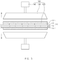
FIG. 3 is a side view of the support member, the heating member, and the moving member when the lamination apparatus is stopped according to the first embodiment of the present invention. -
FIG. 4 is a perspective view illustrating the support member of the lamination apparatus according to the first embodiment of the present invention. -
FIG. 5 is a flowchart illustrating a lamination method according to the first embodiment of the present invention. -
FIG. 6 is a perspective view illustrating a support member of a lamination apparatus according to a second embodiment of the present invention. - Hereinafter, embodiments of the present invention will be described in detail with reference to the accompanying drawings in such a manner that the technical idea of the present invention may easily be carried out by a person with ordinary skill in the art to which the invention pertains. The present invention may, however, be embodied in different forms and should not be construed as limited to the embodiments set forth herein. In the drawings, anything unnecessary for describing the present invention will be omitted for clarity, and also like reference numerals in the drawings denote like elements.
- As illustrated in
FIG. 1 , a lamination apparatus according to a first embodiment of the present invention is configured to thermally bond an electrode assembly in which electrodes and separators are alternately laminated. The lamination apparatus comprises atransfer member 110 transferring theelectrode assembly 10, asupport member 120 supporting each of the outermost top and bottom surfaces of theelectrode assembly 10 that is transferred by thetransfer member 110, aheating member 130 heating theelectrode assembly 10 supported by thesupport member 120, and a movingmember 140 moving the heating member in a direction that is away from theelectrode assembly 10. - The
transfer member 110 transfers theelectrode assembly 10, in which the electrodes and the separators are alternately laminated, up to arolling member 150 via theheating member 130. For example, thetransfer member 110 is provided as a transfer roller or a conveyor belt to transfer the electrode assembly at a predetermined time and interval. - The
transfer member 110 further comprises an electrode transfer part and a separator transfer part, which respectively transfer the electrodes and the separators. The electrode transfer part comprises a firstelectrode transfer part 111 transferring afirst electrode 11 and a secondelectrode transfer part 113 transferring asecond electrode 13. The separator transfer part comprises a firstseparator transfer part 112 transferring afirst separator 12 and a secondseparator transfer part 114 transferring asecond separator 14. - As described above, the
transfer member 110 may sequentially laminate thefirst electrode 11, thefirst separator 12, thesecond electrode 13, and thesecond separator 14, which are transferred through the electrode transfer part and the separator transfer part, to manufacture theelectrode assembly 10. The manufacturedelectrode assembly 10 is transferred up to therolling member 150 via theheating member 130. - The
transfer member 110 further comprises afirst cutter 115 cutting each of thefirst electrode 11 transferred by the firstelectrode transfer part 111 and thesecond electrode 13 transferred by the secondelectrode transfer part 113 into a predetermined size. - Also, the
transfer member 110 further comprises asecond cutter 116 cutting theelectrode assembly 10, which is bonded through the rollingmember 150, into a predetermined size. Thesecond cutter 116 cuts the separator between the electrodes corresponding to each other, which are provided in the bondedelectrode assembly 10, to obtain anelectrode assembly 10 having a predetermined size. - The
support member 120 is configured to support the electrode assembly transferred by thetransfer member 110. Thesupport member 120 has a rectangular plate shape and supports each of the outermost top and bottom surfaces of theelectrode assembly 10. Here, thesupport member 120 may press theelectrode assembly 10 in a range in which the transferring of theelectrode assembly 10 transferred by thetransfer member 110 does not interfere. Thus, theelectrode assembly 10 transferred by thetransfer member 110 may be significantly prevented from being tilted. - As illustrated in
FIG. 4 , thesupport member 120 may comprise ametal plate 121 having thermal conductivity. Thus, thesupport member 120 may transfer heat capacity transferred by theheating member 130 to theelectrode assembly 10 as it is to effectively heat theelectrode assembly 10. That is, even though thesupport member 120 is disposed between theelectrode assembly 10 and theheating member 130, theelectrode assembly 100 may be stably heated. - Here, the
metal plate 121 may have a thickness of 2 mm to 10 mm, particularly, a thickness of 3 mm to 5 mm. That is, when themetal plate 121 has a thickness of 2 mm or less, heat of theheating member 130 may be reliably transferred to theelectrode assembly 10 without loss of heat capacity. However, themetal plate 121 may be easily bent. When themetal plate 121 has a thickness of 10 mm or more, although the bending of themetal plate 121 is solved, the loss of the heat capacity may occur. As a result, it is difficult to stably heat theelectrode assembly 10. - Also, the
metal plate 121 may have anopening groove 121a in an outer surface thereof, which does not face theelectrode assembly 10. Thus, themetal plate 121 supporting theelectrode assembly 10 may decrease in thickness through theopening groove 121a. Thus, the heat may be transferred to theelectrode assembly 10 without the loss of the heat capacity, and thus, themetal plate 121 by which theelectrode assembly 10 is not supported may increase in thickness of an edge thereof to prevent theelectrode assembly 10 from being deformed. - The
metal plate 121 may have a rectangular frame shape. Thus, themetal plate 121 may stably support theelectrode assembly 10 and also stably heat theelectrode assembly 10 because the heat capacity of the heating member is transferred as it is to theelectrode assembly 10. - The
support member 120 may further comprise a heat-resistant plate 122 on an inner surface of the metal plate, on which theelectrode assembly 10 is supported. Theelectrode assembly 10 may be supported on the heat-resistant plate 122 to prevent the electrode assembly from being damaged. Particularly, the heat-resistant plate 122 may be provided in the form of a film, and thus, be applied or attached to the inner surface of themetal plate 121 to improve convenience and efficiency in use. - The
support member 120 may have an area greater than that of theelectrode assembly 10. Thus, thesupport member 120 may stably support the entire top or bottom surface of theelectrode assembly 10. - The
heating member 130 may be disposed outside thesupport member 120 to heat theelectrode assembly 10 supported by thesupport member 120. Here, theheating member 130 may be closely attached to the outside of thesupport member 120. Thus, the heat capacity of theheating member 130 may be more stably transferred to theelectrode assembly 10. - The
heating member 130 may be a heating device that generates heat by power supplied from the outside. - The moving
member 140 may be configured to separate the electrode assembly from the heating member so that the heat source of the heating member is not transferred to theelectrode assembly 10. The movingmember 140 moves theheating member 130 in a direction that is away from theelectrode assembly 10 supported by thesupport member 120. That is, when viewed inFIGS. 2 and3 , the movingmember 140 may move theheating member 130 in an upward or downward direction that is away from theelectrode assembly 10. Thus, the movingmember 140 may block or minimize the transferring of the heat source of theheating member 130 into theelectrode assembly 10 to prevent theelectrode assembly 10 from being heated by theheating member 130. - That is, as illustrated in
FIG. 2 , the movingmember 140 allows theheating member 130 to be closely attached to the outside of thesupport member 120 when thetransfer member 110 operates so that theheating member 130 stably heats theelectrode assembly 10 supported by thesupport member 120. - As illustrated in
FIG. 3 , the movingmember 140 moves theheating member 130 in the direction that is away from theelectrode assembly 10 when thetransfer member 110 is stopped to prevent theelectrode assembly 10 from being heated by theheating member 130, thereby preventing deformation and defects of theelectrode assembly 10 from occurring. - Here, although the heat source of the heating member is maintained as it is, the electrode assembly may be prevented from being heated by the
heating member 130. - Also, the
support member 120 may support theelectrode assembly 10 even though theheating member 130 is moved. Thus, the electrode provided in theelectrode assembly 10 may be prevented from being tilted between the separators. - Thereafter, when the
transfer member 110 is restarted, the movingmember 140 may allow theheating member 130 to return to its original position. Thus, theelectrode assembly 10 may be reheated without waiting time to improve continuity and efficiency of the operation. - The rolling
member 150 may be provided in a pair to roll the top and bottom surfaces of theelectrode assembly 10 that is heated by theheating member 130. Thus, the electrode and the separator, which are provided in theelectrode assembly 10, may be bonded to each other to improve bonding therebetween. - Thus, the lamination apparatus according to the first embodiment of the present invention is characterized in that when the
transfer member 110 is stopped, theheating member 130 is moved in the direction that is away from theelectrode assembly 10 by the movingmember 140. Thus, theelectrode assembly 10 may be prevented from being heated by theheating member 130 to prevent the deformation and the defects of the electrode assembly from occurring. Particularly, the heat capacity of the heating member may be maintained as it is. Thus, when the transfer member is restarted, if the heating member is located at its original position by the movingmember 140, the electrode assembly may be reheated without a separate standby time to improve the continuity and efficiency of the operation. - Hereinafter, a lamination method using the lamination apparatus according to the first embodiment of the present invention will be described.
- As illustrated in
FIG. 5 , a lamination method according to the first embodiment of the present invention comprises a transfer step (S10) of transferring anelectrode assembly 10 through atransfer member 110, a support step (S20) of supporting each of top and bottom surfaces of theelectrode assembly 10 transferred by thetransfer member 110, a heating step (S30) of heating theelectrode assembly 10 supported by thesupport member 120 through aheating member 130 provided outside the support member, and a bonding step (S40) of rolling and bonding theelectrode assembly 10 heated by theheating member 130 through a rollingmember 150. - In the transfer step (S10), the
electrode assembly 10 is transferred up to the rollingmember 150 via theheating member 130 through thetransfer member 110. Thetransfer member 110 further comprises an electrode transfer part and a separator transfer part, which respectively transfer electrodes and separators so that the electrodes and the separators are alternately laminated. The electrode transfer part comprises a firstelectrode transfer part 111 transferring afirst electrode 11 and a secondelectrode transfer part 113 transferring asecond electrode 13. The separator transfer part comprises a firstseparator transfer part 112 transferring afirst separator 12 and a secondseparator transfer part 114 transferring asecond separator 14. - That is, in the transfer step, the
first electrode 11, thefirst separator 12, thesecond electrode 13, and thesecond separator 14 may be transferred to be sequentially laminated to manufacture theelectrode assembly 10, and the manufacturedelectrode assembly 10 is transferred up to the rollingmember 150 via theheating member 130. - In the transfer step (S10), a
first cutter 115 for cutting each of thefirst electrode 11 and thesecond electrode 13, which are transferred, into a predetermined size is used. Thefirst electrode 11 and thesecond electrode 13, each of which is cut into the predetermined size by thefirst cutter 115, are alternately laminated together with thefirst separator 12 and thesecond separator 14 to manufacture theelectrode assembly 10. - In the support step (S20), each of the outermost top and bottom surfaces of the
electrode assembly 10 that is transferred in the transfer step (S10) is supported by thesupport member 120 to prevent theelectrode assembly 10 from being tilted. - In the heating step (S30), the
electrode assembly 10 supported by thesupport member 120 is heated to increase in temperature through theheating member 130 provided outside thesupport member 120. - The bonding step (S40), the
electrode assembly 10 heated by theheating member 130 is rolled by the rollingmember 150 to improve bonding between the electrode and the separator, which are provided in theelectrode assembly 10. - In the bonding step (S40), a
second cutter 116 for cutting the bondedelectrode assembly 10 in a predetermined size is used. Thesecond cutter 116 cuts each of thefirst separator 12 and thesecond separator 14, which are disposed between the electrodes corresponding to each other, to manufacture the electrode assembly having a predetermined size. - Here, as illustrated in
FIGS. 3 and4 , a non-heating process (S35) in which theheating member 130 is moved in a direction that is away from the electrode assembly through a movingmember 140 when thetransfer member 110 is stopped to prevent theelectrode assembly 10 from being heated by theheating member 130 may be further performed between the heating step (S30) and the bonding step (S40). - That is, the non-heating process (S35) is performed to prevent one
electrode assembly 10 from being continuously heated by theheating member 130 when thetransfer member 120 is stopped. Here, theheating member 130 may be moved in the direction that is away from theelectrode assembly 10 supported by thesupport member 120 through the movingmember 140, and thus, even though hat capacity of the heating member is maintained as it is, a heat source of theheating member 130 may be effectively prevented from being transferred to theelectrode assembly 10 to prevent deformation and defects of theelectrode assembly 10 from occurring. - Here, even though the
support member 120 moves theheating member 130, thesupport member 120 may support the electrode assembly as it is to prevent thefirst electrode 11 and thesecond electrode 13, which are provided in theelectrode assembly 10, from being tilted. - Particularly, the
support member 120 may transfer the heat capacity transferred from theheating member 130 to theelectrode assembly 10 as it is by ametal plate 121 having thermal conductivity. Thus, theelectrode assembly 10 may be stably heated. - Also, the
support member 120 may prevent theelectrode assembly 10 from being damaged by a heat-resistant plate 122 disposed on an inner surface of themetal plate 121. - As illustrated in
FIG. 2 , a reheating process (S37) in which theheating member 130 returns to its original position when thetransfer member 110 is restarted to reheat theelectrode assembly 10 supported by thesupport member 120 through theheating member 130 is further performed between the non-heating process (S35) and the bonding step (S40). - That is, in the reheating process (S37), when the
transfer member 110 is restarted to transfer theelectrode assembly 10, theheating member 130 returns to its original position through the movingmember 140. Here, since the heat capacity of theheating member 130 is maintained as it is, theelectrode assembly 10 being transferred may be reheated without a separate standby time to improve continuity and efficiency of an operation. - Hereinafter, in descriptions of another embodiment of the present invention, constituents having the same configuration and function as the abovementioned embodiment have been given the same reference numeral in the drawings, and thus duplicated description will be omitted.
- As illustrated in
FIG. 6 , a lamination apparatus according to a second embodiment of the present invention comprises a support member 120'. The support member 120' comprises a heat-resistant plate 122' supported on the electrode assembly and a metal plate 121' that is disposed on an edge of an outer surface of the heat-resistant plate 122', by which theelectrode assembly 10 is not supported, and allows the heat-resistant plate 122' to increase in strength. - That is, the support member 120' comprises the metal plate 120' on only the edge of the outer surface of the heat-resistant plate 122'. Particularly, the support member 120' may be provided on only two sides facing each other of the heat-resistant plate 122'. Thus, the heat-resistant plate 122' may increase in strength, and the heat capacity transferred by the
heating member 130 may be effectively transferred to theelectrode assembly 10 without a loss of the heat capacity to stably heating theelectrode assembly 10. - Accordingly, the scope of the present invention is defined by the appended claims rather than the foregoing description and the exemplary embodiments described therein. Various modifications made within the meaning of an equivalent of the claims of the invention and within the claims are to be regarded to be in the scope of the present invention.
Claims (11)
- A lamination apparatus for a secondary battery, which thermally bonds an electrode assembly in which electrodes and separators are alternately laminated, the lamination apparatus comprising:a transfer member transferring the electrode assembly;a support member supporting each of top and bottom surfaces of the electrode assembly transferred by the transfer member;a heating member disposed outside the support member to heat the electrode assembly supported by the support member; anda moving member moving the heating member in a direction that is away from the electrode assembly.
- The lamination apparatus of claim 1, wherein the moving member moves the heating member in the direction that is away from the electrode assembly when the transfer member is stopped to prevent the electrode assembly from being heated by the heating member.
- The lamination apparatus of claim 2, wherein the moving member allows the heating member to return to its original position when the transfer member is restarted to reheat the electrode assembly.
- The lamination apparatus of claim 1, wherein the heating member is maintained in heat capacity as it is even though the heating member is moved by the moving member.
- The lamination apparatus of claim 1, wherein the support member supports each of the top and bottom surfaces of the electrode assembly even though the heating member is moved to prevent the electrode assembly from being tilted.
- The lamination apparatus of claim 1, wherein the support member comprises a metal plate having thermal conductivity.
- The lamination apparatus of claim 6, wherein the support member further comprises a heat-resistant plate disposed on an inner surface of the metal plate on which the electrode assembly is supported.
- The lamination apparatus of claim 1, wherein the support member comprises a heat-resistant plate supported on the electrode assembly and a metal plate disposed on an edge of an outer surface of the heat-resistant plate, by which the electrode assembly is not supported, to allow the heat-resistant to increase in strength.
- A lamination method for a secondary battery, the lamination method comprising:a transfer step (S10) of transferring an electrode assembly through a transfer member;a support step (S20) of supporting each of top and bottom surfaces of the electrode assembly transferred by the transfer member;a heating step (S30) of heating the electrode assembly supported by the support member through the heating member provided outside the support member; anda bonding step (S40) of rolling and bonding the electrode assembly heated by the heating member through a rolling member.
- The lamination method of claim 9, further comprising a non-heating process (S35), in which the heating member is moved in a direction that is away from the electrode assembly through a moving member when the transfer member is stopped to prevent the electrode assembly from being heated by the heating member, between the heating step (S30) and the bonding step (S40).
- The lamination method of claim 10, further comprising a reheating process (S37), in which the heating member returns to its original position when the transfer member is restarted to reheat the electrode assembly supported by the support member through the heating member, between the non-heating process (S35) and the bonding step (S40).
Applications Claiming Priority (2)
| Application Number | Priority Date | Filing Date | Title |
|---|---|---|---|
| KR1020170138385A KR102223722B1 (en) | 2017-10-24 | 2017-10-24 | Lamination apparatus and method for secondary battery |
| PCT/KR2018/011306 WO2019083174A1 (en) | 2017-10-24 | 2018-09-21 | Lamination apparatus and method for secondary battery |
Publications (3)
| Publication Number | Publication Date |
|---|---|
| EP3557675A1 true EP3557675A1 (en) | 2019-10-23 |
| EP3557675A4 EP3557675A4 (en) | 2020-05-27 |
| EP3557675B1 EP3557675B1 (en) | 2024-01-24 |
Family
ID=66247855
Family Applications (1)
| Application Number | Title | Priority Date | Filing Date |
|---|---|---|---|
| EP18870526.3A Active EP3557675B1 (en) | 2017-10-24 | 2018-09-21 | Lamination apparatus and method for secondary battery |
Country Status (7)
| Country | Link |
|---|---|
| US (2) | US11563232B2 (en) |
| EP (1) | EP3557675B1 (en) |
| KR (1) | KR102223722B1 (en) |
| CN (1) | CN110121810B (en) |
| ES (1) | ES2969558T3 (en) |
| HU (1) | HUE065133T2 (en) |
| WO (1) | WO2019083174A1 (en) |
Cited By (1)
| Publication number | Priority date | Publication date | Assignee | Title |
|---|---|---|---|---|
| EP4109612A4 (en) * | 2020-03-25 | 2023-09-13 | LG Energy Solution, Ltd. | APPARATUS AND METHOD FOR MANUFACTURING UNIT CELLS |
Families Citing this family (10)
| Publication number | Priority date | Publication date | Assignee | Title |
|---|---|---|---|---|
| JP7156046B2 (en) * | 2019-01-14 | 2022-10-19 | トヨタ自動車株式会社 | LAMINATE PRESSING DEVICE, METHOD FOR MANUFACTURING PRESSED STRIP LAMINATE, METHOD FOR MANUFACTURING LAMINATED ELECTRODE, AND METHOD FOR MANUFACTURING BATTERY |
| KR102841147B1 (en) * | 2019-05-29 | 2025-07-31 | 주식회사 엘지에너지솔루션 | Radical unit, lamination apparatus and method for secondary battery |
| KR102468395B1 (en) | 2019-07-22 | 2022-11-16 | 주식회사 엘지에너지솔루션 | Separator Sealing Device and Sealing Method to Prevent Folding of separator |
| KR102849367B1 (en) | 2020-03-25 | 2025-08-25 | 주식회사 엘지에너지솔루션 | The Apparatus And The Method For Manufacturing Unit Cell |
| KR102849368B1 (en) | 2020-03-25 | 2025-08-25 | 주식회사 엘지에너지솔루션 | The Apparatus And The Method For Manufacturing Cell |
| EP4184634B1 (en) * | 2021-01-11 | 2025-11-26 | LG Energy Solution, Ltd. | Cutting device and lamination equipment and method for secondary battery comprising same |
| KR102932144B1 (en) | 2021-01-13 | 2026-02-27 | 주식회사 엘지에너지솔루션 | Electrode assembly laminating equipment with reduced defect rate and manufacturing method of electrode assembly thereby |
| CN115732735B (en) * | 2021-08-31 | 2024-05-31 | 宁德时代新能源科技股份有限公司 | Heating device, battery manufacturing equipment and battery manufacturing method |
| CN216015471U (en) * | 2021-09-23 | 2022-03-11 | 宁德时代新能源科技股份有限公司 | Electrode assembly manufacturing device |
| KR102867412B1 (en) * | 2022-11-09 | 2025-09-30 | 삼성에스디아이 주식회사 | All solid battery and manufacturing method of the same |
Family Cites Families (28)
| Publication number | Priority date | Publication date | Assignee | Title |
|---|---|---|---|---|
| US4289559A (en) * | 1979-10-18 | 1981-09-15 | Murphy Shirley D | Process and apparatus for heat laminating film to a substrate |
| DE4107249A1 (en) * | 1991-03-07 | 1992-09-10 | Roemmler H Resopal Werk Gmbh | METHOD AND DEVICE FOR THE PRODUCTION OF HIGH-PRESSURE LAYER COMPRESSED PLATES |
| US5500604A (en) * | 1994-07-15 | 1996-03-19 | Hughes Aircraft Company | Radial tensioning lamination fixture for membrane test probe |
| JP3432710B2 (en) | 1997-08-21 | 2003-08-04 | 東芝電池株式会社 | Equipment for manufacturing electrode elements for polymer batteries |
| JP2000208140A (en) | 1999-01-13 | 2000-07-28 | Toshiba Battery Co Ltd | Lamination device for polymer battery electrode element |
| AU5163800A (en) * | 1999-05-25 | 2000-12-12 | Leading Edge Technologies, Inc. | Apparatus and method for battery cell electrode preparation, assembly and lamination |
| US20020007552A1 (en) * | 1999-05-25 | 2002-01-24 | Singleton Robert W. | Apparatus and method of manufacturing a battery cell |
| TW499766B (en) * | 2000-03-29 | 2002-08-21 | Elite Ionergy Co Ltd | Battery manufacturing method |
| JP4486373B2 (en) | 2004-02-10 | 2010-06-23 | カシオマイクロニクス株式会社 | LAMINATING METHOD AND LAMINATING APPARATUS USING THE METHOD |
| JP3918004B2 (en) | 2005-04-22 | 2007-05-23 | 日本アビオニクス株式会社 | Semiconductor device repair method |
| JP2008041581A (en) * | 2006-08-10 | 2008-02-21 | Hitachi Maxell Ltd | Winding electrode group, prismatic secondary battery and laminated secondary battery |
| JP5844052B2 (en) | 2011-02-04 | 2016-01-13 | 三洋電機株式会社 | Multilayer battery and method for manufacturing the same |
| JP5901135B2 (en) | 2011-04-07 | 2016-04-06 | 株式会社京都製作所 | Laminating apparatus and laminating method |
| JP2013122831A (en) * | 2011-12-09 | 2013-06-20 | Automotive Energy Supply Corp | Apparatus and method of manufacturing electrode group, and method of manufacturing battery |
| KR101949479B1 (en) * | 2012-08-06 | 2019-02-19 | 스미또모 가가꾸 가부시키가이샤 | Roll member, coating device, separator production device, and secondary battery production device |
| JP2014086265A (en) | 2012-10-24 | 2014-05-12 | Nissan Motor Co Ltd | Separator joining method and device |
| KR101609424B1 (en) * | 2013-09-26 | 2016-04-05 | 주식회사 엘지화학 | Method of manufacturing electrode assembly |
| KR101586121B1 (en) | 2013-09-30 | 2016-01-22 | 주식회사 엘지화학 | Lamination device including electrode guide |
| WO2015050084A1 (en) | 2013-10-02 | 2015-04-09 | 日産自動車株式会社 | Method for bonding separators in electrical device, apparatus for bonding separators in electrical device, and electrical device |
| KR101826894B1 (en) | 2013-11-04 | 2018-02-07 | 주식회사 엘지화학 | Electrode assembly and apparatus for manufacturing the same |
| KR101775230B1 (en) | 2014-10-02 | 2017-09-05 | 주식회사 엘지화학 | Laminating apparatus and method for secondary battery |
| KR101749148B1 (en) * | 2014-10-23 | 2017-06-20 | 주식회사 엘지화학 | Lamination Device Using High-frequency Induction Heating and Secondary Battery Manufactured Using the Same |
| KR101891864B1 (en) * | 2015-02-16 | 2018-08-24 | 주식회사 엘지화학 | Apparatus for Shaping Separator and Battery Cell Manufactured by Using the Same |
| KR101816765B1 (en) * | 2015-06-04 | 2018-01-10 | 주식회사 엘지화학 | A protection film for a lamination of an electrode and a method for manufacturing a secondary battery using the same |
| GB2560481B (en) * | 2015-09-11 | 2019-03-20 | Jeld Wen Uk Ltd | Method and system for assembly of recessed panel doors |
| KR101925090B1 (en) | 2015-11-18 | 2018-12-04 | 주식회사 엘지화학 | Sealing apparatus of secondary battery |
| KR20170090157A (en) | 2016-01-28 | 2017-08-07 | 주식회사 탑앤씨 | Complex Lamination Apparatus of Pouch Film for Secondary Battery |
| JP6787241B2 (en) * | 2017-04-28 | 2020-11-18 | トヨタ自動車株式会社 | Manufacturing method of electrode laminate and battery |
-
2017
- 2017-10-24 KR KR1020170138385A patent/KR102223722B1/en active Active
-
2018
- 2018-09-21 EP EP18870526.3A patent/EP3557675B1/en active Active
- 2018-09-21 HU HUE18870526A patent/HUE065133T2/en unknown
- 2018-09-21 CN CN201880005532.0A patent/CN110121810B/en active Active
- 2018-09-21 WO PCT/KR2018/011306 patent/WO2019083174A1/en not_active Ceased
- 2018-09-21 US US16/476,726 patent/US11563232B2/en active Active
- 2018-09-21 ES ES18870526T patent/ES2969558T3/en active Active
-
2022
- 2022-12-09 US US18/078,761 patent/US12255280B2/en active Active
Cited By (1)
| Publication number | Priority date | Publication date | Assignee | Title |
|---|---|---|---|---|
| EP4109612A4 (en) * | 2020-03-25 | 2023-09-13 | LG Energy Solution, Ltd. | APPARATUS AND METHOD FOR MANUFACTURING UNIT CELLS |
Also Published As
| Publication number | Publication date |
|---|---|
| EP3557675B1 (en) | 2024-01-24 |
| CN110121810B (en) | 2022-05-24 |
| US20230109577A1 (en) | 2023-04-06 |
| WO2019083174A1 (en) | 2019-05-02 |
| US20190363389A1 (en) | 2019-11-28 |
| ES2969558T3 (en) | 2024-05-21 |
| KR20190045602A (en) | 2019-05-03 |
| US11563232B2 (en) | 2023-01-24 |
| US12255280B2 (en) | 2025-03-18 |
| CN110121810A (en) | 2019-08-13 |
| EP3557675A4 (en) | 2020-05-27 |
| KR102223722B1 (en) | 2021-03-05 |
| HUE065133T2 (en) | 2024-05-28 |
Similar Documents
| Publication | Publication Date | Title |
|---|---|---|
| EP3557675B1 (en) | Lamination apparatus and method for secondary battery | |
| KR102442472B1 (en) | Lamination apparatus and method for secondary battery | |
| US9893376B2 (en) | Methods of preparing electrode assembly and secondary battery | |
| CN109244371B (en) | Battery pole piece thermal compounding equipment | |
| EP3738704A1 (en) | Electrode assembly having different-sized pressure-welded portions of electrode tab-welded joint and ultrasonic welding device for manufacturing same | |
| JP2019135699A (en) | Manufacturing method for battery | |
| KR102901180B1 (en) | Method for Manufacturing Electrode Assembly Comprising Step of Simultaneously Applying Heating and Pressure | |
| JP2024541984A (en) | Method and apparatus for laminating battery cell components | |
| US11424474B2 (en) | Secondary battery, and apparatus and method for manufacturing the same | |
| KR20150124611A (en) | Cutting apparatus for secondary battery | |
| US11476491B2 (en) | Electrode pressure-bonding device | |
| EP3211676B1 (en) | Method for producing solar cell module | |
| US11936033B2 (en) | Electrode tab-feeding device including guide for positioning electrode tab at correct point | |
| JP2017098022A (en) | Separator welding device | |
| EP4397469A1 (en) | Sealing device for secondary battery | |
| JP7615434B2 (en) | Electrode assembly, manufacturing apparatus and method thereof | |
| JP2025536784A (en) | Laminating device and method for manufacturing electrode assembly | |
| JP2025519659A (en) | Electrode assembly and manufacturing method thereof | |
| EP4106065B1 (en) | Laminator having improved adhesiveness for producing unit structures | |
| CN116097486A (en) | Battery lamination processing apparatus and method | |
| US10964957B2 (en) | Manufacturing method for fuel cell including a heat adhesion step | |
| KR102688262B1 (en) | Fuel cell manufacturing system | |
| KR20250009931A (en) | Secondary battery and preparation method thereof | |
| KR20250146389A (en) | Secondary battery manufacturing device and secondary battery manufacturing method using the same | |
| CN115642277A (en) | Membrane electrode preparation equipment and preparation method for a fuel cell |
Legal Events
| Date | Code | Title | Description |
|---|---|---|---|
| STAA | Information on the status of an ep patent application or granted ep patent |
Free format text: STATUS: THE INTERNATIONAL PUBLICATION HAS BEEN MADE |
|
| PUAI | Public reference made under article 153(3) epc to a published international application that has entered the european phase |
Free format text: ORIGINAL CODE: 0009012 |
|
| STAA | Information on the status of an ep patent application or granted ep patent |
Free format text: STATUS: REQUEST FOR EXAMINATION WAS MADE |
|
| 17P | Request for examination filed |
Effective date: 20190717 |
|
| AK | Designated contracting states |
Kind code of ref document: A1 Designated state(s): AL AT BE BG CH CY CZ DE DK EE ES FI FR GB GR HR HU IE IS IT LI LT LU LV MC MK MT NL NO PL PT RO RS SE SI SK SM TR |
|
| AX | Request for extension of the european patent |
Extension state: BA ME |
|
| A4 | Supplementary search report drawn up and despatched |
Effective date: 20200430 |
|
| RIC1 | Information provided on ipc code assigned before grant |
Ipc: H01M 10/04 20060101AFI20200423BHEP |
|
| DAV | Request for validation of the european patent (deleted) | ||
| DAX | Request for extension of the european patent (deleted) | ||
| RAP1 | Party data changed (applicant data changed or rights of an application transferred) |
Owner name: LG ENERGY SOLUTION LTD. |
|
| RAP3 | Party data changed (applicant data changed or rights of an application transferred) |
Owner name: LG ENERGY SOLUTION, LTD. |
|
| GRAP | Despatch of communication of intention to grant a patent |
Free format text: ORIGINAL CODE: EPIDOSNIGR1 |
|
| STAA | Information on the status of an ep patent application or granted ep patent |
Free format text: STATUS: GRANT OF PATENT IS INTENDED |
|
| INTG | Intention to grant announced |
Effective date: 20231019 |
|
| P01 | Opt-out of the competence of the unified patent court (upc) registered |
Effective date: 20231030 |
|
| GRAS | Grant fee paid |
Free format text: ORIGINAL CODE: EPIDOSNIGR3 |
|
| GRAA | (expected) grant |
Free format text: ORIGINAL CODE: 0009210 |
|
| STAA | Information on the status of an ep patent application or granted ep patent |
Free format text: STATUS: THE PATENT HAS BEEN GRANTED |
|
| AK | Designated contracting states |
Kind code of ref document: B1 Designated state(s): AL AT BE BG CH CY CZ DE DK EE ES FI FR GB GR HR HU IE IS IT LI LT LU LV MC MK MT NL NO PL PT RO RS SE SI SK SM TR |
|
| REG | Reference to a national code |
Ref country code: GB Ref legal event code: FG4D |
|
| REG | Reference to a national code |
Ref country code: CH Ref legal event code: EP |
|
| REG | Reference to a national code |
Ref country code: IE Ref legal event code: FG4D |
|
| REG | Reference to a national code |
Ref country code: DE Ref legal event code: R096 Ref document number: 602018064630 Country of ref document: DE |
|
| REG | Reference to a national code |
Ref country code: LT Ref legal event code: MG9D |
|
| REG | Reference to a national code |
Ref country code: ES Ref legal event code: FG2A Ref document number: 2969558 Country of ref document: ES Kind code of ref document: T3 Effective date: 20240521 |
|
| REG | Reference to a national code |
Ref country code: HU Ref legal event code: AG4A Ref document number: E065133 Country of ref document: HU |
|
| REG | Reference to a national code |
Ref country code: NL Ref legal event code: MP Effective date: 20240124 |
|
| PG25 | Lapsed in a contracting state [announced via postgrant information from national office to epo] |
Ref country code: NL Free format text: LAPSE BECAUSE OF FAILURE TO SUBMIT A TRANSLATION OF THE DESCRIPTION OR TO PAY THE FEE WITHIN THE PRESCRIBED TIME-LIMIT Effective date: 20240124 |
|
| PG25 | Lapsed in a contracting state [announced via postgrant information from national office to epo] |
Ref country code: NL Free format text: LAPSE BECAUSE OF FAILURE TO SUBMIT A TRANSLATION OF THE DESCRIPTION OR TO PAY THE FEE WITHIN THE PRESCRIBED TIME-LIMIT Effective date: 20240124 |
|
| PG25 | Lapsed in a contracting state [announced via postgrant information from national office to epo] |
Ref country code: IS Free format text: LAPSE BECAUSE OF FAILURE TO SUBMIT A TRANSLATION OF THE DESCRIPTION OR TO PAY THE FEE WITHIN THE PRESCRIBED TIME-LIMIT Effective date: 20240524 |
|
| PG25 | Lapsed in a contracting state [announced via postgrant information from national office to epo] |
Ref country code: LT Free format text: LAPSE BECAUSE OF FAILURE TO SUBMIT A TRANSLATION OF THE DESCRIPTION OR TO PAY THE FEE WITHIN THE PRESCRIBED TIME-LIMIT Effective date: 20240124 |
|
| PG25 | Lapsed in a contracting state [announced via postgrant information from national office to epo] |
Ref country code: GR Free format text: LAPSE BECAUSE OF FAILURE TO SUBMIT A TRANSLATION OF THE DESCRIPTION OR TO PAY THE FEE WITHIN THE PRESCRIBED TIME-LIMIT Effective date: 20240425 |
|
| REG | Reference to a national code |
Ref country code: AT Ref legal event code: MK05 Ref document number: 1652892 Country of ref document: AT Kind code of ref document: T Effective date: 20240124 |
|
| PG25 | Lapsed in a contracting state [announced via postgrant information from national office to epo] |
Ref country code: HR Free format text: LAPSE BECAUSE OF FAILURE TO SUBMIT A TRANSLATION OF THE DESCRIPTION OR TO PAY THE FEE WITHIN THE PRESCRIBED TIME-LIMIT Effective date: 20240124 Ref country code: RS Free format text: LAPSE BECAUSE OF FAILURE TO SUBMIT A TRANSLATION OF THE DESCRIPTION OR TO PAY THE FEE WITHIN THE PRESCRIBED TIME-LIMIT Effective date: 20240424 |
|
| PG25 | Lapsed in a contracting state [announced via postgrant information from national office to epo] |
Ref country code: AT Free format text: LAPSE BECAUSE OF FAILURE TO SUBMIT A TRANSLATION OF THE DESCRIPTION OR TO PAY THE FEE WITHIN THE PRESCRIBED TIME-LIMIT Effective date: 20240124 |
|
| PG25 | Lapsed in a contracting state [announced via postgrant information from national office to epo] |
Ref country code: RS Free format text: LAPSE BECAUSE OF FAILURE TO SUBMIT A TRANSLATION OF THE DESCRIPTION OR TO PAY THE FEE WITHIN THE PRESCRIBED TIME-LIMIT Effective date: 20240424 Ref country code: NO Free format text: LAPSE BECAUSE OF FAILURE TO SUBMIT A TRANSLATION OF THE DESCRIPTION OR TO PAY THE FEE WITHIN THE PRESCRIBED TIME-LIMIT Effective date: 20240424 Ref country code: LT Free format text: LAPSE BECAUSE OF FAILURE TO SUBMIT A TRANSLATION OF THE DESCRIPTION OR TO PAY THE FEE WITHIN THE PRESCRIBED TIME-LIMIT Effective date: 20240124 Ref country code: IS Free format text: LAPSE BECAUSE OF FAILURE TO SUBMIT A TRANSLATION OF THE DESCRIPTION OR TO PAY THE FEE WITHIN THE PRESCRIBED TIME-LIMIT Effective date: 20240524 Ref country code: HR Free format text: LAPSE BECAUSE OF FAILURE TO SUBMIT A TRANSLATION OF THE DESCRIPTION OR TO PAY THE FEE WITHIN THE PRESCRIBED TIME-LIMIT Effective date: 20240124 Ref country code: GR Free format text: LAPSE BECAUSE OF FAILURE TO SUBMIT A TRANSLATION OF THE DESCRIPTION OR TO PAY THE FEE WITHIN THE PRESCRIBED TIME-LIMIT Effective date: 20240425 Ref country code: FI Free format text: LAPSE BECAUSE OF FAILURE TO SUBMIT A TRANSLATION OF THE DESCRIPTION OR TO PAY THE FEE WITHIN THE PRESCRIBED TIME-LIMIT Effective date: 20240124 Ref country code: BG Free format text: LAPSE BECAUSE OF FAILURE TO SUBMIT A TRANSLATION OF THE DESCRIPTION OR TO PAY THE FEE WITHIN THE PRESCRIBED TIME-LIMIT Effective date: 20240124 Ref country code: AT Free format text: LAPSE BECAUSE OF FAILURE TO SUBMIT A TRANSLATION OF THE DESCRIPTION OR TO PAY THE FEE WITHIN THE PRESCRIBED TIME-LIMIT Effective date: 20240124 |
|
| PG25 | Lapsed in a contracting state [announced via postgrant information from national office to epo] |
Ref country code: PL Free format text: LAPSE BECAUSE OF FAILURE TO SUBMIT A TRANSLATION OF THE DESCRIPTION OR TO PAY THE FEE WITHIN THE PRESCRIBED TIME-LIMIT Effective date: 20240124 Ref country code: PT Free format text: LAPSE BECAUSE OF FAILURE TO SUBMIT A TRANSLATION OF THE DESCRIPTION OR TO PAY THE FEE WITHIN THE PRESCRIBED TIME-LIMIT Effective date: 20240524 |
|
| PG25 | Lapsed in a contracting state [announced via postgrant information from national office to epo] |
Ref country code: SE Free format text: LAPSE BECAUSE OF FAILURE TO SUBMIT A TRANSLATION OF THE DESCRIPTION OR TO PAY THE FEE WITHIN THE PRESCRIBED TIME-LIMIT Effective date: 20240124 Ref country code: PT Free format text: LAPSE BECAUSE OF FAILURE TO SUBMIT A TRANSLATION OF THE DESCRIPTION OR TO PAY THE FEE WITHIN THE PRESCRIBED TIME-LIMIT Effective date: 20240524 Ref country code: PL Free format text: LAPSE BECAUSE OF FAILURE TO SUBMIT A TRANSLATION OF THE DESCRIPTION OR TO PAY THE FEE WITHIN THE PRESCRIBED TIME-LIMIT Effective date: 20240124 Ref country code: LV Free format text: LAPSE BECAUSE OF FAILURE TO SUBMIT A TRANSLATION OF THE DESCRIPTION OR TO PAY THE FEE WITHIN THE PRESCRIBED TIME-LIMIT Effective date: 20240124 |
|
| PG25 | Lapsed in a contracting state [announced via postgrant information from national office to epo] |
Ref country code: DK Free format text: LAPSE BECAUSE OF FAILURE TO SUBMIT A TRANSLATION OF THE DESCRIPTION OR TO PAY THE FEE WITHIN THE PRESCRIBED TIME-LIMIT Effective date: 20240124 |
|
| PG25 | Lapsed in a contracting state [announced via postgrant information from national office to epo] |
Ref country code: SM Free format text: LAPSE BECAUSE OF FAILURE TO SUBMIT A TRANSLATION OF THE DESCRIPTION OR TO PAY THE FEE WITHIN THE PRESCRIBED TIME-LIMIT Effective date: 20240124 |
|
| PG25 | Lapsed in a contracting state [announced via postgrant information from national office to epo] |
Ref country code: EE Free format text: LAPSE BECAUSE OF FAILURE TO SUBMIT A TRANSLATION OF THE DESCRIPTION OR TO PAY THE FEE WITHIN THE PRESCRIBED TIME-LIMIT Effective date: 20240124 Ref country code: CZ Free format text: LAPSE BECAUSE OF FAILURE TO SUBMIT A TRANSLATION OF THE DESCRIPTION OR TO PAY THE FEE WITHIN THE PRESCRIBED TIME-LIMIT Effective date: 20240124 |
|
| REG | Reference to a national code |
Ref country code: DE Ref legal event code: R097 Ref document number: 602018064630 Country of ref document: DE |
|
| PG25 | Lapsed in a contracting state [announced via postgrant information from national office to epo] |
Ref country code: SK Free format text: LAPSE BECAUSE OF FAILURE TO SUBMIT A TRANSLATION OF THE DESCRIPTION OR TO PAY THE FEE WITHIN THE PRESCRIBED TIME-LIMIT Effective date: 20240124 |
|
| PG25 | Lapsed in a contracting state [announced via postgrant information from national office to epo] |
Ref country code: SM Free format text: LAPSE BECAUSE OF FAILURE TO SUBMIT A TRANSLATION OF THE DESCRIPTION OR TO PAY THE FEE WITHIN THE PRESCRIBED TIME-LIMIT Effective date: 20240124 Ref country code: SK Free format text: LAPSE BECAUSE OF FAILURE TO SUBMIT A TRANSLATION OF THE DESCRIPTION OR TO PAY THE FEE WITHIN THE PRESCRIBED TIME-LIMIT Effective date: 20240124 Ref country code: RO Free format text: LAPSE BECAUSE OF FAILURE TO SUBMIT A TRANSLATION OF THE DESCRIPTION OR TO PAY THE FEE WITHIN THE PRESCRIBED TIME-LIMIT Effective date: 20240124 Ref country code: EE Free format text: LAPSE BECAUSE OF FAILURE TO SUBMIT A TRANSLATION OF THE DESCRIPTION OR TO PAY THE FEE WITHIN THE PRESCRIBED TIME-LIMIT Effective date: 20240124 Ref country code: DK Free format text: LAPSE BECAUSE OF FAILURE TO SUBMIT A TRANSLATION OF THE DESCRIPTION OR TO PAY THE FEE WITHIN THE PRESCRIBED TIME-LIMIT Effective date: 20240124 Ref country code: CZ Free format text: LAPSE BECAUSE OF FAILURE TO SUBMIT A TRANSLATION OF THE DESCRIPTION OR TO PAY THE FEE WITHIN THE PRESCRIBED TIME-LIMIT Effective date: 20240124 |
|
| PLBE | No opposition filed within time limit |
Free format text: ORIGINAL CODE: 0009261 |
|
| STAA | Information on the status of an ep patent application or granted ep patent |
Free format text: STATUS: NO OPPOSITION FILED WITHIN TIME LIMIT |
|
| PG25 | Lapsed in a contracting state [announced via postgrant information from national office to epo] |
Ref country code: IT Free format text: LAPSE BECAUSE OF FAILURE TO SUBMIT A TRANSLATION OF THE DESCRIPTION OR TO PAY THE FEE WITHIN THE PRESCRIBED TIME-LIMIT Effective date: 20240124 |
|
| PG25 | Lapsed in a contracting state [announced via postgrant information from national office to epo] |
Ref country code: IT Free format text: LAPSE BECAUSE OF FAILURE TO SUBMIT A TRANSLATION OF THE DESCRIPTION OR TO PAY THE FEE WITHIN THE PRESCRIBED TIME-LIMIT Effective date: 20240124 |
|
| 26N | No opposition filed |
Effective date: 20241025 |
|
| PG25 | Lapsed in a contracting state [announced via postgrant information from national office to epo] |
Ref country code: SI Free format text: LAPSE BECAUSE OF FAILURE TO SUBMIT A TRANSLATION OF THE DESCRIPTION OR TO PAY THE FEE WITHIN THE PRESCRIBED TIME-LIMIT Effective date: 20240124 Ref country code: MC Free format text: LAPSE BECAUSE OF FAILURE TO SUBMIT A TRANSLATION OF THE DESCRIPTION OR TO PAY THE FEE WITHIN THE PRESCRIBED TIME-LIMIT Effective date: 20240124 |
|
| REG | Reference to a national code |
Ref country code: CH Ref legal event code: PL |
|
| PG25 | Lapsed in a contracting state [announced via postgrant information from national office to epo] |
Ref country code: LU Free format text: LAPSE BECAUSE OF NON-PAYMENT OF DUE FEES Effective date: 20240921 |
|
| PGFP | Annual fee paid to national office [announced via postgrant information from national office to epo] |
Ref country code: BE Payment date: 20250424 Year of fee payment: 8 |
|
| PG25 | Lapsed in a contracting state [announced via postgrant information from national office to epo] |
Ref country code: CH Free format text: LAPSE BECAUSE OF NON-PAYMENT OF DUE FEES Effective date: 20240930 |
|
| PG25 | Lapsed in a contracting state [announced via postgrant information from national office to epo] |
Ref country code: IE Free format text: LAPSE BECAUSE OF NON-PAYMENT OF DUE FEES Effective date: 20240921 |
|
| PGFP | Annual fee paid to national office [announced via postgrant information from national office to epo] |
Ref country code: DE Payment date: 20250820 Year of fee payment: 8 |
|
| PGFP | Annual fee paid to national office [announced via postgrant information from national office to epo] |
Ref country code: HU Payment date: 20250929 Year of fee payment: 8 Ref country code: GB Payment date: 20250820 Year of fee payment: 8 |
|
| PGFP | Annual fee paid to national office [announced via postgrant information from national office to epo] |
Ref country code: FR Payment date: 20250821 Year of fee payment: 8 |
|
| PG25 | Lapsed in a contracting state [announced via postgrant information from national office to epo] |
Ref country code: CY Free format text: LAPSE BECAUSE OF FAILURE TO SUBMIT A TRANSLATION OF THE DESCRIPTION OR TO PAY THE FEE WITHIN THE PRESCRIBED TIME-LIMIT; INVALID AB INITIO Effective date: 20180921 |
|
| PGFP | Annual fee paid to national office [announced via postgrant information from national office to epo] |
Ref country code: ES Payment date: 20251007 Year of fee payment: 8 |