EP3557582B1 - Failure detection apparatus, failure detection method, and failure detection program - Google Patents
Failure detection apparatus, failure detection method, and failure detection program Download PDFInfo
- Publication number
- EP3557582B1 EP3557582B1 EP19169194.8A EP19169194A EP3557582B1 EP 3557582 B1 EP3557582 B1 EP 3557582B1 EP 19169194 A EP19169194 A EP 19169194A EP 3557582 B1 EP3557582 B1 EP 3557582B1
- Authority
- EP
- European Patent Office
- Prior art keywords
- failure detection
- ram
- area
- controller
- processing
- Prior art date
- Legal status (The legal status is an assumption and is not a legal conclusion. Google has not performed a legal analysis and makes no representation as to the accuracy of the status listed.)
- Active
Links
Images


Classifications
-
- G—PHYSICS
- G06—COMPUTING OR CALCULATING; COUNTING
- G06F—ELECTRIC DIGITAL DATA PROCESSING
- G06F11/00—Error detection; Error correction; Monitoring
- G06F11/07—Responding to the occurrence of a fault, e.g. fault tolerance
- G06F11/08—Error detection or correction by redundancy in data representation, e.g. by using checking codes
- G06F11/10—Adding special bits or symbols to the coded information, e.g. parity check, casting out 9's or 11's
- G06F11/1008—Adding special bits or symbols to the coded information, e.g. parity check, casting out 9's or 11's in individual solid state devices
- G06F11/1048—Adding special bits or symbols to the coded information, e.g. parity check, casting out 9's or 11's in individual solid state devices using arrangements adapted for a specific error detection or correction feature
-
- G—PHYSICS
- G06—COMPUTING OR CALCULATING; COUNTING
- G06F—ELECTRIC DIGITAL DATA PROCESSING
- G06F11/00—Error detection; Error correction; Monitoring
- G06F11/07—Responding to the occurrence of a fault, e.g. fault tolerance
- G06F11/0703—Error or fault processing not based on redundancy, i.e. by taking additional measures to deal with the error or fault not making use of redundancy in operation, in hardware, or in data representation
- G06F11/0706—Error or fault processing not based on redundancy, i.e. by taking additional measures to deal with the error or fault not making use of redundancy in operation, in hardware, or in data representation the processing taking place on a specific hardware platform or in a specific software environment
- G06F11/0712—Error or fault processing not based on redundancy, i.e. by taking additional measures to deal with the error or fault not making use of redundancy in operation, in hardware, or in data representation the processing taking place on a specific hardware platform or in a specific software environment in a virtual computing platform, e.g. logically partitioned systems
-
- G—PHYSICS
- G06—COMPUTING OR CALCULATING; COUNTING
- G06F—ELECTRIC DIGITAL DATA PROCESSING
- G06F11/00—Error detection; Error correction; Monitoring
- G06F11/30—Monitoring
- G06F11/3003—Monitoring arrangements specially adapted to the computing system or computing system component being monitored
- G06F11/301—Monitoring arrangements specially adapted to the computing system or computing system component being monitored where the computing system is a virtual computing platform, e.g. logically partitioned systems
-
- G—PHYSICS
- G06—COMPUTING OR CALCULATING; COUNTING
- G06F—ELECTRIC DIGITAL DATA PROCESSING
- G06F3/00—Input arrangements for transferring data to be processed into a form capable of being handled by the computer; Output arrangements for transferring data from processing unit to output unit, e.g. interface arrangements
- G06F3/06—Digital input from, or digital output to, record carriers, e.g. RAID, emulated record carriers or networked record carriers
- G06F3/0601—Interfaces specially adapted for storage systems
- G06F3/0602—Interfaces specially adapted for storage systems specifically adapted to achieve a particular effect
- G06F3/0614—Improving the reliability of storage systems
- G06F3/0619—Improving the reliability of storage systems in relation to data integrity, e.g. data losses, bit errors
-
- G—PHYSICS
- G06—COMPUTING OR CALCULATING; COUNTING
- G06F—ELECTRIC DIGITAL DATA PROCESSING
- G06F3/00—Input arrangements for transferring data to be processed into a form capable of being handled by the computer; Output arrangements for transferring data from processing unit to output unit, e.g. interface arrangements
- G06F3/06—Digital input from, or digital output to, record carriers, e.g. RAID, emulated record carriers or networked record carriers
- G06F3/0601—Interfaces specially adapted for storage systems
- G06F3/0628—Interfaces specially adapted for storage systems making use of a particular technique
- G06F3/0638—Organizing or formatting or addressing of data
- G06F3/0644—Management of space entities, e.g. partitions, extents, pools
-
- G—PHYSICS
- G06—COMPUTING OR CALCULATING; COUNTING
- G06F—ELECTRIC DIGITAL DATA PROCESSING
- G06F3/00—Input arrangements for transferring data to be processed into a form capable of being handled by the computer; Output arrangements for transferring data from processing unit to output unit, e.g. interface arrangements
- G06F3/06—Digital input from, or digital output to, record carriers, e.g. RAID, emulated record carriers or networked record carriers
- G06F3/0601—Interfaces specially adapted for storage systems
- G06F3/0668—Interfaces specially adapted for storage systems adopting a particular infrastructure
- G06F3/0671—In-line storage system
- G06F3/0673—Single storage device
- G06F3/0679—Non-volatile semiconductor memory device, e.g. flash memory, one time programmable memory [OTP]
-
- G—PHYSICS
- G11—INFORMATION STORAGE
- G11C—STATIC STORES
- G11C29/00—Checking stores for correct operation ; Subsequent repair; Testing stores during standby or offline operation
- G11C29/04—Detection or location of defective memory elements, e.g. cell constructio details, timing of test signals
- G11C29/08—Functional testing, e.g. testing during refresh, power-on self testing [POST] or distributed testing
-
- G—PHYSICS
- G11—INFORMATION STORAGE
- G11C—STATIC STORES
- G11C29/00—Checking stores for correct operation ; Subsequent repair; Testing stores during standby or offline operation
- G11C29/04—Detection or location of defective memory elements, e.g. cell constructio details, timing of test signals
- G11C2029/0409—Online test
Definitions
- the present disclosure relates to a failure detection apparatus, a failure detection method, and a failure detection program for detecting failure of memory.
- patent literature (PTL) 1 discloses an apparatus for performing diagnostics on a safety mechanism (SM) random access memory (RAM) area of RAM.
- SM safety mechanism
- RAM random access memory
- WO 2015 147 829 A1 discloses a method of cyclically performing progressive RAM tests during normal operation of an embedded system.
- US 8862952 B1 discloses a data storage system configured to perform prioritized memory scanning for memory errors.
- the data storage system prioritizes scanning for memory errors based on a quality attribute of pages or zones of a non-volatile memory array. Pages or zones having quality attributes that reflect a lower level of reliability or endurance than other pages or zones are scanned more frequently for memory errors. When memory errors are discovered, the quality attribute of pages or zones can be adjusted to reflect a lower level of reliability or endurance.
- stored data can be recovered before it may become permanently lost and before a host system reads the stored data.
- EP 2 963 716 A1 discloses a combustion device and a fuel cell system in which a failure in a control device is detected and upon such failure detection, a fuel cut-off valve can be surely closed.
- Each of safety control portions includes the error detecting portion, which can detect own abnormality and abnormality of other safety control portions, and the fuel shutoff control portion which shuts off the supply of a fuel by driving the power source shutoff device so as to shut off the supply of a power source voltage to the fuel shutoff valves in a case where abnormality is detected by the error detecting portion.
- US 7 246 269 B1 discloses a method and apparatus provided for use in testing a memory coupled to a processing node.
- a background scrubber in the processing node is initialized to perform a test of the memory.
- a status of the background scrubber is checked in which the status indicates whether an error occurred during the test.
- a predetermined action is taken in response to the status indicating that the error occurred during the test.
- the apparatus disclosed in PTL 1 merely performs diagnostics on the SMRAM area, which is a portion of the RAM.
- the apparatus disclosed in PTL 1 therefore cannot detect failure occurring in an undiagnosed area.
- the controller may be configured to execute processing related to detection of a property of a liquid. This configuration can detect properties of liquids.
- a failure detection method is a failure detection method to be executed by a failure detection apparatus including a RAM.
- the RAM includes a plurality of partitioned areas generated by partitioning the entire area of the RAM.
- the failure detection method includes executing processing related to detection of a physical quantity in a predetermined sampling period and executing sequential failure detection on a portion of the plurality of partitioned areas during a time when the processing is not being executed in each of a plurality of the sampling periods. This configuration allows execution of failure processing on all of the areas of the RAM, including the areas that affect operation of a sensor apparatus.
- a failure detection program is for causing a failure detection apparatus, which includes a RAM that includes a plurality of partitioned areas generated by partitioning the entire area of the RAM, to execute the steps of executing processing related to detection of a physical quantity in a predetermined sampling period and executing sequential failure detection on a portion of the plurality of partitioned areas during a time when the processing is not being executed in each of a plurality of the sampling periods.
- This configuration allows execution of failure processing on the entire area of the RAM, including the areas that affect operation of a sensor apparatus.
- the present disclosure can provide a failure detection apparatus, a failure detection method, and a failure detection program capable of executing failure detection on all areas of RAM.
- FIG. 1 is a functional block diagram illustrating an example schematic configuration of a safety instrumented system 1 according to an embodiment.
- the safety instrumented system 1 is, for example, provided on an operation line in a plant.
- the safety instrumented system 1 is a system provided to suspend the plant in a safe state during an emergency, such as when an abnormality occurs in a device on the operation line. Having the safety instrumented system 1 stop operation of the plant during an emergency can prevent disasters such as explosions or fatal accidents, environmental pollution, and the like and can protect equipment.
- Examples of the plant include an industrial plant such as a chemical plant; a plant for managing a well site, such as a gas field or oil field, and the surrounding area; a plant for managing power generation such as hydroelectric power, thermal power, nuclear power, or the like; a plant for managing environmental power generation such as solar power, wind power, or the like; and a plant for managing water and sewage, a dam, or the like.
- the plant is not, however, limited to these examples.
- the example safety instrumented system 1 illustrated in FIG. 1 includes a sensor apparatus 10, a calculation controller 11, and a safety apparatus 12.
- the sensor apparatus 10 functions as a failure detection apparatus that performs failure detection on internal RAM.
- the sensor apparatus 10 is an apparatus for executing processing related to detection of a predetermined physical quantity on the operation line.
- the processing related to detection of a predetermined physical quantity includes detection of the predetermined physical quantity and output of a signal corresponding to the detected physical quantity.
- the predetermined physical quantity may be determined appropriately in accordance with properties of the devices, substances, and the like used on the operation line.
- the sensor apparatus 10 transmits a signal corresponding to the detected physical quantity to the calculation controller 11. In the example in FIG. 1 , the sensor apparatus 10 transmits a signal corresponding to the detected physical quantity to the calculation controller 11 using a 4 mA to 20 mA current.
- the sensor apparatus 10 transmits a current in a range of 4 mA to 20 mA to the calculation controller 11 in accordance with the value of the detected physical quantity.
- the predetermined physical quantity that the sensor apparatus 10 detects is described as being the hydrogen ion exponent (pH) of a fluid used in the operation line.
- the predetermined physical quantity is not, however, limited to pH.
- the processing executed by the sensor apparatus 10 is also referred to as "sensor processing".
- the sensor processing includes processing related to detection of a physical quantity.
- the sensor apparatus 10 includes a sensor element 110 and a signal converter 120.
- FIG. 2 is a functional block diagram illustrating an example schematic configuration of the sensor apparatus 10.
- the sensor element 110 is an element for detecting the above-described predetermined physical quantity.
- the sensor element 110 is a sensor element capable of detecting the pH of a fluid.
- the signal converter 120 receives an electric signal outputted by the sensor element 110 on the basis of the detection result, performs digital signal processing on the electric signal, and outputs a current of 4 mA to 20 mA to the calculation controller 11 on the basis of the result of the digital signal processing.
- the signal converter 120 includes an analog-to-digital (A/D) converter 121, a controller 122, an output interface 123, read only memory (ROM) 124, and RAM 125.
- A/D analog-to-digital
- the A/D converter 121 converts an analog electric signal, outputted by the sensor element 110 on the basis of the detection result, to a digital signal.
- the controller 122 controls and manages the signal converter 120 overall, starting with the functional blocks of the signal converter 120.
- the controller 122 may be configured as software executed by a suitable processor, such as a central processing unit (CPU), or configured as a dedicated processor specialized for each process.
- the controller 122 performs predetermined calculation processing on the digital signal converted by the A/D converter 121.
- the controller 122 stores the result of the calculation processing (calculation result) in the RAM 125, for example.
- the controller 122 also converts the calculation result stored in the RAM 125 to a 4 mA to 20 mA current and outputs the current periodically, for example, to the calculation controller 11.
- the output interface 123 is an interface for outputting signals to the calculation controller 11 on the basis of control by the controller 122.
- the output interface 123 outputs 4 mA to 20 mA current signals to the calculation controller 11 on the basis of control by the controller 122.
- the ROM 124 functions as a memory of the signal converter 120.
- the ROM 124 stores programs executed by the controller 122, for example.
- the RAM 125 functions as a memory of the signal converter 120.
- the RAM 125 stores the calculation result from the controller 122, for example.
- FIG. 3 schematically illustrates an example of data areas in the RAM 125.
- the RAM 125 includes an operating system (OS) area 126, a stack area 127, a data area for program operation control 128, and a calculation result storage area 129 as data areas.
- the OS area 126 is an area storing software for the controller 122 to operate.
- the stack area 127 is an area for temporarily storing data during execution of processing by the controller 122.
- the data area for program operation control 128 is an area for storing data used when running programs. Data such as the number of measurements for calculating an average is stored here.
- the calculation result storage area 129 is an area for storing the result of calculation processing that the controller 122 executes on the digital signal converted by the A/D converter 121, as described above.
- the calculation controller 11 receives a current signal from the sensor apparatus 10.
- the calculation controller 11 executes safety control logic for implementing safety control.
- the calculation controller 11 transmits a control signal to the safety apparatus 12 to cause the safety apparatus 12 to execute predetermined control.
- the calculation controller 11 may be constituted by a mechanism known as a logic solver.
- the safety apparatus 12 executes predetermined control on the basis of the control signal received from the calculation controller 11. For example, on the basis of the control signal received from the calculation controller 11, the safety apparatus 12 executes control to stop the operation line.
- the safety apparatus 12 may, for example, be formed by a valve positioner, an electromagnetic valve, or the like.
- the calculation controller 11 transmits a control signal to the safety apparatus 12 to close the valve.
- the safety apparatus 12 configured as a valve positioner or an electromagnetic valve can, for example, stop the supply of a fluid to the line by closing the valve in response to the control signal received from the calculation controller 11.
- a safety integrity level is known as an index related to the likelihood of fulfilling a safety function.
- the safety integrity level is classified into four stages from SIL1 to SIL4, where SIL1 indicates the lowest level of safety, and SIL4 indicates the highest level of safety.
- the SIL may, for example, be determined in accordance with the functional safety standard IEC 61508.
- the SIL of the safety instrumented system 1 is, for example, determined by the product of the probability of failure on demand (PFD) of each constituent element of the safety instrumented system 1.
- PFD probability of failure on demand
- the SIL is determined by the product of the PFDs of the sensor apparatus 10, the calculation controller 11, and the safety apparatus 12.
- the index indicated by the SIL classification increases.
- safety is higher.
- the sensor apparatus 10 of the safety instrumented system 1 includes the RAM 125, as described with reference to FIG. 2 . Failure more easily occurs in the RAM 125, however, than in the other functional units. In other words, the PFD of the RAM 125 tends to increase. The PFD of the RAM 125 therefore tends to have a large effect on the SIL of the safety instrumented system 1. Hence, the SIL of the safety instrumented system 1 overall can easily be increased by improving the PFD of the RAM 125.
- failure detection is executed on the entire RAM 125 upon startup of the safety instrumented system 1, for example, whereas during operation of the RAM 125, failure detection is executed on the calculation result storage area 129 among the areas of the RAM 125. Failure detection is only executed on the calculation result storage area 129 during operation of the RAM 125, however, and failure detection is not executed on other areas that affect operation of the safety instrumented system 1.
- the other areas that affect operation of the safety instrumented system 1 are the OS area 126, the stack area 127, and the data area for program operation control 128.
- operation of the RAM 125 needs to stop if failure detection is to be executed on areas other than the calculation result storage area 129, such as the OS area 126, during operation of the RAM 125. Stopping operation of the RAM 125 and executing failure detection, however, hinders operation of the safety instrumented system 1. Stopping operation of the RAM 125 to execute failure detection is therefore not realistic.
- the RAM 125 included an error check and correct (ECC) function
- ECC error check and correct
- the RAM 125 could execute failure detection on the entire RAM 125 by executing ECC-based failure detection, even during operation of the RAM 125.
- the ECC function is capable of detecting that an error has occurred in data stored in the RAM 125 and of correcting the erroneous data.
- RAM 125 with an ECC function is more expensive than RAM 125 without an ECC function. Hence, the cost of the safety instrumented system 1 increases upon using RAM 125 with an ECC function.
- the present disclosure therefore provides a failure detection apparatus, a failure detection method, and a failure detection program capable of using a less expensive RAM 125, without an ECC function, to execute failure detection during operation of the RAM 125.
- failure detection executed by the sensor apparatus 10 is described.
- failure detection executed on the entire area of the RAM 125 requires approximately several hundred milliseconds to several seconds, for example. It is unrealistic, however, to stop the RAM 125 for several hundred milliseconds to several seconds while the RAM 125 is operating, as described above.
- the sensor apparatus 10 executes sequential failure detection on a plurality of elements yielded by partitioning the entire area of the RAM 125 and thus divides up the entire area of the RAM 125 to perform failure detection.
- FIG. 4 illustrates a method of failure detection executed by the sensor apparatus 10 according to the present embodiment.
- the upper and lower tiers of FIG. 4 are time charts illustrating processing executed by the sensor apparatus 10.
- the horizontal axis in FIG. 4 represents time.
- the time chart in the lower tier of FIG. 4 indicates processing when the sensor apparatus 10 executes failure detection at once on the entire area of the RAM 125.
- a predetermined time T 0 is required for failure detection of the entire area of the RAM 125.
- the predetermined time T 0 is several hundred milliseconds to several seconds, for example.
- the time chart in the upper tier of FIG. 4 illustrates failure detection processing executed by the sensor apparatus 10 according to the present embodiment.
- the sensor apparatus 10 uses a plurality of elements generated by partitioning the entire area of the RAM 125.
- the partitioned elements generated by partitioning the entire area of the RAM 125 are also referred to as "partitioned areas" in the present disclosure.
- the time chart in the lower tier of FIG. 4 illustrates an example of partitioned areas yielded by partitioning the entire area of the RAM 125.
- the partitioned areas of the RAM 125 may be determined in advance and set in the sensor apparatus 10.
- the partitioned areas may be partitioned by a different classification than the example data areas of the RAM 125 illustrated in FIG. 3 .
- the partitioned areas need not be the four areas consisting of the OS area 126, the stack area 127, the data area for program operation control 128, and the calculation result storage area 129.
- the OS area 126, the stack area 127, the data area for program operation control 128, and the calculation result storage area 129 may each be further partitioned to form the partitioned areas.
- each partitioned area belongs to one of the OS area 126, the stack area 127, the data area for program operation control 128, and the calculation result storage area 129.
- the sensor apparatus 10 executes the sensor processing over a certain sampling period T 1 , for example.
- the sampling period T 1 may be set appropriately in accordance with the physical quantity to be detected, the specifications of the sensor element 110, and the like, for example.
- the sensor apparatus 10 executes sensor processing. For example, the sensor apparatus 10 executes processing to detect a physical quantity during each sampling period T 1 .
- the sensor processing that the sensor apparatus 10 executes can be completed without taking up the entire sampling period T 1 .
- the predetermined time T 2 is also referred to below as the sensor processing time T 2 .
- the sensor apparatus 10 executes failure detection during the time T 3 , within each sampling period T 1 , when sensor processing is not being executed. At this time, the sensor apparatus 10 executes failure detection on one partitioned area of the RAM 125.
- the time T 3 is also referred to below as the failure detection time T 3 .
- the sensor apparatus 10 repeatedly alternates between sensor processing during the sensor processing time T 2 and failure detection during the failure detection time T 3 in the sampling periods T 1 .
- the sensor apparatus 10 executes sequential failure detection on all of the partitioned areas.
- the sensor apparatus 10 thus sequentially executes failure detection on the partitioned areas in the sampling periods T 1 .
- the sensor apparatus 10 can execute failure detection on the entire area of the RAM 125 by cycling through the same number of sampling periods T 1 as the number of partitioned areas.
- the time required for the sensor apparatus 10 according to the present embodiment to complete failure detection once on the entire area of the RAM 125 is also referred to below as the failure detection period T D .
- the failure detection period T D includes the same number of sampling periods T 1 as the number of partitioned areas of the RAM 125.
- the sensor apparatus 10 executes sequential failure detection on the partitioned areas of the RAM 125 in this way during the failure detection time T 3 , which is a portion of each sampling period T 1 .
- the sensor apparatus 10 can thereby execute failure detection on the entire area of the RAM 125 within the failure detection period T D .
- FIG. 5 is a flowchart illustrating an example of processing executed by the sensor apparatus 10 during the failure detection time T 3 .
- the sensor apparatus 10 executes failure detection on one partitioned area by executing the processing illustrated as an example in FIG. 5 during the failure detection time T 3 .
- FIG. 6 illustrates partitioned areas generated by partitioning the entire area of the RAM 125.
- the RAM 125 has N partitioned areas (N > 1), from area 1 to area N, as the partitioned areas for executing failure detection. Data, for example, is stored in each partitioned area.
- the sensor apparatus 10 executes failure detection sequentially on the N partitioned areas from area 1 to area N during the failure detection time T 3 of each sampling period T 1 .
- the procedures in FIG. 5 illustrate an example of failure detection processing on area 1 among the partitioned areas.
- FIG. 7 schematically illustrates example registers included in the controller 122 of the signal converter 120.
- the procedures in FIG. 5 are executed by the controller 122, which includes at least five registers from R0 to R4, as in the example in FIG. 7 .
- the controller 122 executes processing to disable interrupts at the start of the failure detection time T 3 (step S10). Consequently, processing other than failure detection does not interrupt. In other words, processing other than the processing illustrated in the procedures of FIG. 5 will not be executed.
- the controller 122 transfers the data (DATA 1) stored in area 1 of the RAM 125 to register R3 of the controller 122 to store the DATA 1 in register R3 (step S11).
- the controller 122 thus temporarily saves the DATA 1 that was stored in area 1 in register R3.
- the controller 122 then writes the value "0x55555555” as the DATA 1 of area 1 (step S12).
- "0x55555555” is a value represented as "01010101" in a 32-bit pattern.
- the controller 122 calculates the exclusive OR of the DATA 1 and "0x55555555” and saves the calculation result in register R2 (step S13).
- the calculation result saved in register R2 is 0 if area 1 is normal.
- the controller 122 then writes the value "0xAAAAAAAA” as the DATA 1 of area 1 (step S14).
- "0xAAAAAAAA” is a value represented as "10101010" in a 32-bit pattern.
- the controller 122 calculates the OR of i) the exclusive OR of the DATA 1 and "0xAAAAAAAA” and ii) the calculation result saved in register R2 in step S13.
- the controller 122 saves the calculation result in register R0 (step S15).
- the exclusive OR of the DATA 1 and "0xAAAAAAAA” is 0 if area 1 is normal. Accordingly, the calculation result saved in register R0 is 0 if area 1 is normal. Conversely, the calculation result saved in register R0 is a value other than 0 if an abnormality is present in area 1.
- the controller 122 stores the original data that was saved in register R3 in area 1 (step S16). In this way, the controller 122 restores the original data that was stored in area 1.
- the controller 122 executes processing enabling interrupts (step S17). Consequently, processing other than failure detection can interrupt and be executed.
- the controller 122 judges whether the calculation result saved in register R0 is 0 (step S18).
- step S18 Yes
- the controller 122 judges that area 1 is normal and terminates the procedures.
- step S18 when judging that the calculation result saved in register R0 is not 0 (step S18: No), the controller 122 judges that an abnormality exists in area 1 and executes error processing (step S19). As the error processing, the controller 122 provides notification of the occurrence of an error, for example. The controller 122 then terminates the procedures.
- the controller 122 executes the procedures in FIG. 5 to execute sequential failure detection on the partitioned areas from area 1 to area N.
- the controller 122 can thus execute failure detection on the entire area of the RAM 125 within the failure detection period T D .
- the sensor apparatus 10 executes failure detection during the failure detection time T 3 , in which sensor processing is not being executed, within each sampling period T 1 on the partitioned areas yielded by partitioning the RAM 125.
- the sensor apparatus 10 can therefore execute failure processing on all of the areas of the RAM 125, including the areas that affect operation of the sensor apparatus 10, i.e. the OS area 126, the stack area 127, and the data area for program operation control 128.
- the sensor apparatus 10 can execute failure detection without affecting the sensor processing executed by the sensor apparatus 10.
- the sensor apparatus 10 can execute failure detection without impairing the functions in the safety instrumented system 1.
- the sensor apparatus 10 Since the sensor apparatus 10 according to the present embodiment executes failure detection on the entire area of the RAM 125, the probability of overlooking failure of the RAM 125 is lower than when failure detection is only executed on a portion of the area of the RAM 125. The PFD of the sensor apparatus 10 thus decreases. Consequently, the PFD of the safety instrumented system 1 overall can be reduced, improving the SIL.
- the SIL of the safety instrumented system 1 has been described in the above embodiment as being determined by the product of the PFDs of the constituent elements of the safety instrumented system 1.
- the SIL of the safety instrumented system 1 may, however, be determined on the basis of the safe failure fraction (SFF) and the fault tolerance (FT).
- SFF safe failure fraction
- FT fault tolerance
- the SIL may be determined so that the index indicated by the SIL classification increases as the SFF is higher or as the FT is higher.
- the sensor apparatus 10 has been described as executing failure detection on one partitioned area of the RAM 125 during the failure detection time T 3 of each sampling period T 1 .
- the target of failure detection that the sensor apparatus 10 executes during the failure detection time T 3 of each sampling period T 1 is not limited to being one partitioned area.
- the sensor apparatus 10 may execute failure detection on two or more partitioned areas of the RAM 125 during the failure detection time T 3 of each sampling period T 1 . This approach may, for example, be taken only when failure detection can be executed on two or more partitioned areas during the failure detection time T 3 .
- the sensor apparatus 10 may execute failure detection on a portion of the plurality of partitioned areas of the RAM 125 during the failure detection time T 3 of each sampling period T 1 .
- the sensor apparatus 10 executes failure detection on two or more partitioned areas during the failure detection time T 3 of each sampling period T 1 , the sensor apparatus 10 can execute failure detection processing on the entire RAM 125 earlier than when executing failure detection on one partitioned area. In other words, the failure detection period T D can be shortened.
- the sensor apparatus 10 may execute failure detection on a priority basis on a specific partitioned area that is a portion of the plurality of partitioned areas.
- executing failure detection on a priority basis refers to executing failure detection on the specific partitioned area before the other partitioned areas, i.e. at an earlier stage in the failure detection period T D .
- the specific partitioned area on which failure detection is executed on a priority basis may, for example, be determined in advance and set in the sensor apparatus 10.
- Specific partitioned areas may, for example, be areas that could affect the SIL classification among the plurality of partitioned areas. Executing failure detection on a priority basis on specific partitioned areas facilitates earlier detection of failure in the specific partitioned areas.
- the specific partitioned areas may be the partitioned areas belonging to the calculation result storage area 129.
- the sensor apparatus 10 may in this case execute failure detection on a priority basis on the partitioned areas belonging to the calculation result storage area 129 as the specific partitioned area.
- failure occurs outside of the calculation result storage area 129, for example in the OS area 126, the sensor apparatus 10 operates abnormally, and failure of the sensor apparatus 10 can be discovered.
- failure occurs in the calculation result storage area 129, it is difficult to judge whether the calculation result is normal or abnormal, making it difficult to discover failure of the sensor apparatus 10.
- the occurrence of failure in the calculation result storage area 129 may result in a normal calculation result not being output, and the safety instrumented system 1 may stop operating normally.
- the sensor apparatus 10 has been described as an apparatus for detecting a predetermined physical quantity on an operation line.
- a longer sampling period T 1 is suitable for the failure detection method described in the above embodiment.
- the reason is that a longer failure detection time T 3 can more easily be set aside as the sampling period T 1 is longer, allowing more time to be used for failure detection in each sampling period T 1 .
- the properties of liquids generally tend to change more gradually than the properties of gases.
- the sensor apparatus 10 may therefore be an apparatus that detects the properties of a liquid or the change in the properties of the liquid as the predetermined physical quantity in the operation line. This is not, however, meant to exclude the sensor apparatus 10 from being an apparatus that detects the properties of a gas or the change in the properties of the gas.
Landscapes
- Engineering & Computer Science (AREA)
- Theoretical Computer Science (AREA)
- Physics & Mathematics (AREA)
- General Engineering & Computer Science (AREA)
- General Physics & Mathematics (AREA)
- Human Computer Interaction (AREA)
- Quality & Reliability (AREA)
- Computing Systems (AREA)
- Mathematical Physics (AREA)
- Computer Security & Cryptography (AREA)
- Testing And Monitoring For Control Systems (AREA)
- For Increasing The Reliability Of Semiconductor Memories (AREA)
- Test And Diagnosis Of Digital Computers (AREA)
- Testing Or Calibration Of Command Recording Devices (AREA)
Description
- The present disclosure relates to a failure detection apparatus, a failure detection method, and a failure detection program for detecting failure of memory.
- Apparatuses for performing diagnostics on memory are known. For example, patent literature (PTL) 1 discloses an apparatus for performing diagnostics on a safety mechanism (SM) random access memory (RAM) area of RAM.
- PTL 1:
JP2016170567A -
WO 2015 147 829 A1 discloses a method of cyclically performing progressive RAM tests during normal operation of an embedded system. -
US 8862952 B1 discloses a data storage system configured to perform prioritized memory scanning for memory errors. The data storage system prioritizes scanning for memory errors based on a quality attribute of pages or zones of a non-volatile memory array. Pages or zones having quality attributes that reflect a lower level of reliability or endurance than other pages or zones are scanned more frequently for memory errors. When memory errors are discovered, the quality attribute of pages or zones can be adjusted to reflect a lower level of reliability or endurance. In addition, stored data can be recovered before it may become permanently lost and before a host system reads the stored data. -
EP 2 963 716 A1 -
US 7 246 269 B1 discloses a method and apparatus provided for use in testing a memory coupled to a processing node. A background scrubber in the processing node is initialized to perform a test of the memory. A status of the background scrubber is checked in which the status indicates whether an error occurred during the test. A predetermined action is taken in response to the status indicating that the error occurred during the test. - The apparatus disclosed in
PTL 1, however, merely performs diagnostics on the SMRAM area, which is a portion of the RAM. The apparatus disclosed inPTL 1 therefore cannot detect failure occurring in an undiagnosed area. - It is an objective of the present disclosure to provide a failure detection apparatus, a failure detection method, and a failure detection program capable of executing failure detection on all areas of RAM.
- The above object is achieved by a failure detection apparatus according to
claim 1, a failure detection method and a failure detection program according to claim 4. The dependent claims are directed to different advantageous aspects of the invention. - In a failure detection apparatus according to an embodiment, the controller may be configured to execute processing related to detection of a property of a liquid. This configuration can detect properties of liquids.
- A failure detection method according to an embodiment is a failure detection method to be executed by a failure detection apparatus including a RAM. The RAM includes a plurality of partitioned areas generated by partitioning the entire area of the RAM. The failure detection method includes executing processing related to detection of a physical quantity in a predetermined sampling period and executing sequential failure detection on a portion of the plurality of partitioned areas during a time when the processing is not being executed in each of a plurality of the sampling periods. This configuration allows execution of failure processing on all of the areas of the RAM, including the areas that affect operation of a sensor apparatus.
- A failure detection program according to an embodiment is for causing a failure detection apparatus, which includes a RAM that includes a plurality of partitioned areas generated by partitioning the entire area of the RAM, to execute the steps of executing processing related to detection of a physical quantity in a predetermined sampling period and executing sequential failure detection on a portion of the plurality of partitioned areas during a time when the processing is not being executed in each of a plurality of the sampling periods. This configuration allows execution of failure processing on the entire area of the RAM, including the areas that affect operation of a sensor apparatus.
- The present disclosure can provide a failure detection apparatus, a failure detection method, and a failure detection program capable of executing failure detection on all areas of RAM.
- In the accompanying drawings:
-
FIG. 1 is a functional block diagram illustrating an example schematic configuration of a safety instrumented system according to an embodiment; -
FIG. 2 is a functional block diagram illustrating an example schematic configuration of the sensor apparatus illustrated inFIG. 1 ; -
FIG. 3 schematically illustrates an example of data areas in the RAM ofFIG. 2 ; -
FIG. 4 illustrates a method of failure detection executed by the sensor apparatus ofFIG. 1 ; -
FIG. 5 is a flowchart illustrating an example of processing executed by the sensor apparatus ofFIG. 1 during time T3; -
FIG. 6 illustrates partitioned areas generated by partitioning the entire area of RAM; and -
FIG. 7 schematically illustrates an example of registers included in a controller of the signal converter inFIG. 2 . - Embodiments of the present disclosure are now described with reference to the drawings.
-
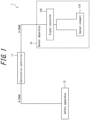
FIG. 1 is a functional block diagram illustrating an example schematic configuration of a safety instrumentedsystem 1 according to an embodiment. The safety instrumentedsystem 1 is, for example, provided on an operation line in a plant. The safety instrumentedsystem 1 is a system provided to suspend the plant in a safe state during an emergency, such as when an abnormality occurs in a device on the operation line. Having the safety instrumentedsystem 1 stop operation of the plant during an emergency can prevent disasters such as explosions or fatal accidents, environmental pollution, and the like and can protect equipment. Examples of the plant include an industrial plant such as a chemical plant; a plant for managing a well site, such as a gas field or oil field, and the surrounding area; a plant for managing power generation such as hydroelectric power, thermal power, nuclear power, or the like; a plant for managing environmental power generation such as solar power, wind power, or the like; and a plant for managing water and sewage, a dam, or the like. The plant is not, however, limited to these examples. - The example safety instrumented
system 1 illustrated inFIG. 1 includes asensor apparatus 10, acalculation controller 11, and asafety apparatus 12. In the safety instrumentedsystem 1, thesensor apparatus 10 functions as a failure detection apparatus that performs failure detection on internal RAM. - The
sensor apparatus 10 is an apparatus for executing processing related to detection of a predetermined physical quantity on the operation line. The processing related to detection of a predetermined physical quantity includes detection of the predetermined physical quantity and output of a signal corresponding to the detected physical quantity. The predetermined physical quantity may be determined appropriately in accordance with properties of the devices, substances, and the like used on the operation line. Thesensor apparatus 10 transmits a signal corresponding to the detected physical quantity to thecalculation controller 11. In the example inFIG. 1 , thesensor apparatus 10 transmits a signal corresponding to the detected physical quantity to thecalculation controller 11 using a 4 mA to 20 mA current. In other words, thesensor apparatus 10 transmits a current in a range of 4 mA to 20 mA to thecalculation controller 11 in accordance with the value of the detected physical quantity. In the present disclosure, the predetermined physical quantity that thesensor apparatus 10 detects is described as being the hydrogen ion exponent (pH) of a fluid used in the operation line. The predetermined physical quantity is not, however, limited to pH. In the present disclosure, the processing executed by thesensor apparatus 10 is also referred to as "sensor processing". The sensor processing includes processing related to detection of a physical quantity. - As illustrated in
FIG. 1 , thesensor apparatus 10 includes asensor element 110 and asignal converter 120.FIG. 2 is a functional block diagram illustrating an example schematic configuration of thesensor apparatus 10. - The
sensor element 110 is an element for detecting the above-described predetermined physical quantity. Here, thesensor element 110 is a sensor element capable of detecting the pH of a fluid. - The
signal converter 120 receives an electric signal outputted by thesensor element 110 on the basis of the detection result, performs digital signal processing on the electric signal, and outputs a current of 4 mA to 20 mA to thecalculation controller 11 on the basis of the result of the digital signal processing. - In the example in
FIG. 2 , thesignal converter 120 includes an analog-to-digital (A/D)converter 121, acontroller 122, anoutput interface 123, read only memory (ROM) 124, andRAM 125. - The A/
D converter 121 converts an analog electric signal, outputted by thesensor element 110 on the basis of the detection result, to a digital signal. - The
controller 122 controls and manages thesignal converter 120 overall, starting with the functional blocks of thesignal converter 120. Thecontroller 122 may be configured as software executed by a suitable processor, such as a central processing unit (CPU), or configured as a dedicated processor specialized for each process. - In accordance with a program stored in the
ROM 124, for example, thecontroller 122 performs predetermined calculation processing on the digital signal converted by the A/D converter 121. Thecontroller 122 stores the result of the calculation processing (calculation result) in theRAM 125, for example. Thecontroller 122 also converts the calculation result stored in theRAM 125 to a 4 mA to 20 mA current and outputs the current periodically, for example, to thecalculation controller 11. - The
output interface 123 is an interface for outputting signals to thecalculation controller 11 on the basis of control by thecontroller 122. Here, theoutput interface 123 outputs 4 mA to 20 mA current signals to thecalculation controller 11 on the basis of control by thecontroller 122. - The
ROM 124 functions as a memory of thesignal converter 120. TheROM 124 stores programs executed by thecontroller 122, for example. - The
RAM 125 functions as a memory of thesignal converter 120. TheRAM 125 stores the calculation result from thecontroller 122, for example. -
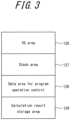
FIG. 3 schematically illustrates an example of data areas in theRAM 125. As illustrated inFIG. 3 , theRAM 125 includes an operating system (OS)area 126, astack area 127, a data area forprogram operation control 128, and a calculationresult storage area 129 as data areas. TheOS area 126 is an area storing software for thecontroller 122 to operate. Thestack area 127 is an area for temporarily storing data during execution of processing by thecontroller 122. The data area forprogram operation control 128 is an area for storing data used when running programs. Data such as the number of measurements for calculating an average is stored here. The calculationresult storage area 129 is an area for storing the result of calculation processing that thecontroller 122 executes on the digital signal converted by the A/D converter 121, as described above. - Referring again to
FIG. 1 , thecalculation controller 11 receives a current signal from thesensor apparatus 10. Thecalculation controller 11 executes safety control logic for implementing safety control. When judging, for example on the basis of the received current signal, that an abnormality has occurred, thecalculation controller 11 transmits a control signal to thesafety apparatus 12 to cause thesafety apparatus 12 to execute predetermined control. Thecalculation controller 11 may be constituted by a mechanism known as a logic solver. - The
safety apparatus 12 executes predetermined control on the basis of the control signal received from thecalculation controller 11. For example, on the basis of the control signal received from thecalculation controller 11, thesafety apparatus 12 executes control to stop the operation line. - The
safety apparatus 12 may, for example, be formed by a valve positioner, an electromagnetic valve, or the like. When judging, on the basis of the received current signal, that an abnormality has occurred, thecalculation controller 11 transmits a control signal to thesafety apparatus 12 to close the valve. Thesafety apparatus 12 configured as a valve positioner or an electromagnetic valve can, for example, stop the supply of a fluid to the line by closing the valve in response to the control signal received from thecalculation controller 11. - In the safety instrumented
system 1 illustrated as an example inFIG. 1 , a safety integrity level (SIL) is known as an index related to the likelihood of fulfilling a safety function. The safety integrity level is classified into four stages from SIL1 to SIL4, where SIL1 indicates the lowest level of safety, and SIL4 indicates the highest level of safety. The SIL may, for example, be determined in accordance with the functional safety standard IEC 61508. - The SIL of the safety instrumented
system 1 is, for example, determined by the product of the probability of failure on demand (PFD) of each constituent element of the safety instrumentedsystem 1. In other words, in the example safety instrumentedsystem 1 illustrated inFIG. 1 , the SIL is determined by the product of the PFDs of thesensor apparatus 10, thecalculation controller 11, and thesafety apparatus 12. As the product of the PFDs of the constituent elements is lower, the index indicated by the SIL classification increases. In other words, as the product of the PFDs of the constituent elements is lower, safety is higher. - The
sensor apparatus 10 of the safety instrumentedsystem 1 includes theRAM 125, as described with reference toFIG. 2 . Failure more easily occurs in theRAM 125, however, than in the other functional units. In other words, the PFD of theRAM 125 tends to increase. The PFD of theRAM 125 therefore tends to have a large effect on the SIL of the safety instrumentedsystem 1. Hence, the SIL of the safety instrumentedsystem 1 overall can easily be increased by improving the PFD of theRAM 125. - In a known technique, failure detection is executed on the
entire RAM 125 upon startup of the safety instrumentedsystem 1, for example, whereas during operation of theRAM 125, failure detection is executed on the calculationresult storage area 129 among the areas of theRAM 125. Failure detection is only executed on the calculationresult storage area 129 during operation of theRAM 125, however, and failure detection is not executed on other areas that affect operation of the safety instrumentedsystem 1. In the example inFIG. 3 , the other areas that affect operation of the safety instrumentedsystem 1 are theOS area 126, thestack area 127, and the data area forprogram operation control 128. Furthermore, operation of theRAM 125 needs to stop if failure detection is to be executed on areas other than the calculationresult storage area 129, such as theOS area 126, during operation of theRAM 125. Stopping operation of theRAM 125 and executing failure detection, however, hinders operation of the safety instrumentedsystem 1. Stopping operation of theRAM 125 to execute failure detection is therefore not realistic. - On the other hand, if the
RAM 125 included an error check and correct (ECC) function, theRAM 125 could execute failure detection on theentire RAM 125 by executing ECC-based failure detection, even during operation of theRAM 125. The ECC function is capable of detecting that an error has occurred in data stored in theRAM 125 and of correcting the erroneous data. However,RAM 125 with an ECC function is more expensive thanRAM 125 without an ECC function. Hence, the cost of the safety instrumentedsystem 1 increases upon usingRAM 125 with an ECC function. - The present disclosure therefore provides a failure detection apparatus, a failure detection method, and a failure detection program capable of using a less
expensive RAM 125, without an ECC function, to execute failure detection during operation of theRAM 125. - Here, a concrete method of failure detection executed by the
sensor apparatus 10 according to the present embodiment is described. Suppose that failure detection executed on the entire area of theRAM 125 requires approximately several hundred milliseconds to several seconds, for example. It is unrealistic, however, to stop theRAM 125 for several hundred milliseconds to several seconds while theRAM 125 is operating, as described above. - To address this issue, the
sensor apparatus 10 according to the present embodiment executes sequential failure detection on a plurality of elements yielded by partitioning the entire area of theRAM 125 and thus divides up the entire area of theRAM 125 to perform failure detection. -
FIG. 4 illustrates a method of failure detection executed by thesensor apparatus 10 according to the present embodiment. The upper and lower tiers ofFIG. 4 are time charts illustrating processing executed by thesensor apparatus 10. The horizontal axis inFIG. 4 represents time. - The time chart in the lower tier of
FIG. 4 indicates processing when thesensor apparatus 10 executes failure detection at once on the entire area of theRAM 125. When failure detection is executed at once on the entire area of theRAM 125, a predetermined time T0 is required for failure detection of the entire area of theRAM 125. As described above, the predetermined time T0 is several hundred milliseconds to several seconds, for example. When failure detection is thus executed at once on the entire area of theRAM 125, operation of theRAM 125 needs to be stopped for the predetermined time T0. - The time chart in the upper tier of
FIG. 4 illustrates failure detection processing executed by thesensor apparatus 10 according to the present embodiment. During failure detection, thesensor apparatus 10 according to the present embodiment uses a plurality of elements generated by partitioning the entire area of theRAM 125. The partitioned elements generated by partitioning the entire area of theRAM 125 are also referred to as "partitioned areas" in the present disclosure. The time chart in the lower tier ofFIG. 4 illustrates an example of partitioned areas yielded by partitioning the entire area of theRAM 125. In the present embodiment, the partitioned areas of theRAM 125 may be determined in advance and set in thesensor apparatus 10. - The partitioned areas may be partitioned by a different classification than the example data areas of the
RAM 125 illustrated inFIG. 3 . In other words, the partitioned areas need not be the four areas consisting of theOS area 126, thestack area 127, the data area forprogram operation control 128, and the calculationresult storage area 129. For example, theOS area 126, thestack area 127, the data area forprogram operation control 128, and the calculationresult storage area 129 may each be further partitioned to form the partitioned areas. In this case, each partitioned area belongs to one of theOS area 126, thestack area 127, the data area forprogram operation control 128, and the calculationresult storage area 129. - As illustrated in the time chart in the upper tier in
FIG. 4 , thesensor apparatus 10 according to the present embodiment executes the sensor processing over a certain sampling period T1, for example. The sampling period T1 may be set appropriately in accordance with the physical quantity to be detected, the specifications of thesensor element 110, and the like, for example. - During each the sampling period T1, the
sensor apparatus 10 executes sensor processing. For example, thesensor apparatus 10 executes processing to detect a physical quantity during each sampling period T1. The sensor processing that thesensor apparatus 10 executes can be completed without taking up the entire sampling period T1. For example, in each sampling period T1, thesensor apparatus 10 can complete the sensor processing to be executed during the sampling period T1 within a predetermined time T2 after the start of sampling (where T1 > T2). In other words, thesensor apparatus 10 does not execute sensor processing in each sampling period T1 during a time T3 yielded by subtracting the predetermined time T2 from the sampling period T1 (where T1 = T2 + T3). The predetermined time T2 is also referred to below as the sensor processing time T2. - The
sensor apparatus 10 according to the present embodiment executes failure detection during the time T3, within each sampling period T1, when sensor processing is not being executed. At this time, thesensor apparatus 10 executes failure detection on one partitioned area of theRAM 125. The time T3 is also referred to below as the failure detection time T3. - The
sensor apparatus 10 repeatedly alternates between sensor processing during the sensor processing time T2 and failure detection during the failure detection time T3 in the sampling periods T1. During the failure detection times T3 of the sampling periods T1, thesensor apparatus 10 executes sequential failure detection on all of the partitioned areas. Thesensor apparatus 10 thus sequentially executes failure detection on the partitioned areas in the sampling periods T1. Thesensor apparatus 10 can execute failure detection on the entire area of theRAM 125 by cycling through the same number of sampling periods T1 as the number of partitioned areas. The time required for thesensor apparatus 10 according to the present embodiment to complete failure detection once on the entire area of theRAM 125 is also referred to below as the failure detection period TD. - The failure detection period TD includes the same number of sampling periods T1 as the number of partitioned areas of the
RAM 125. Thesensor apparatus 10 according to the present embodiment executes sequential failure detection on the partitioned areas of theRAM 125 in this way during the failure detection time T3, which is a portion of each sampling period T1. Thesensor apparatus 10 can thereby execute failure detection on the entire area of theRAM 125 within the failure detection period TD. -
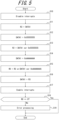
FIG. 5 is a flowchart illustrating an example of processing executed by thesensor apparatus 10 during the failure detection time T3. Thesensor apparatus 10 executes failure detection on one partitioned area by executing the processing illustrated as an example inFIG. 5 during the failure detection time T3. -
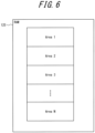
FIG. 6 illustrates partitioned areas generated by partitioning the entire area of theRAM 125. As illustrated inFIG. 6 , theRAM 125 has N partitioned areas (N > 1), fromarea 1 to area N, as the partitioned areas for executing failure detection. Data, for example, is stored in each partitioned area. Thesensor apparatus 10 executes failure detection sequentially on the N partitioned areas fromarea 1 to area N during the failure detection time T3 of each sampling period T1. The procedures inFIG. 5 illustrate an example of failure detection processing onarea 1 among the partitioned areas. -
FIG. 7 schematically illustrates example registers included in thecontroller 122 of thesignal converter 120. In the present embodiment, the procedures inFIG. 5 are executed by thecontroller 122, which includes at least five registers from R0 to R4, as in the example inFIG. 7 . - As illustrated in
FIG. 5 , thecontroller 122 executes processing to disable interrupts at the start of the failure detection time T3 (step S10). Consequently, processing other than failure detection does not interrupt. In other words, processing other than the processing illustrated in the procedures ofFIG. 5 will not be executed. - Next, the
controller 122 transfers the data (DATA 1) stored inarea 1 of theRAM 125 to register R3 of thecontroller 122 to store theDATA 1 in register R3 (step S11). Thecontroller 122 thus temporarily saves theDATA 1 that was stored inarea 1 in register R3. - The
controller 122 then writes the value "0x55555555" as theDATA 1 of area 1 (step S12). "0x55555555" is a value represented as "01010101..." in a 32-bit pattern. - The
controller 122 calculates the exclusive OR of theDATA 1 and "0x55555555" and saves the calculation result in register R2 (step S13). Here, since "0x55555555" was written in theDATA 1 in step S12, the calculation result saved in register R2 is 0 ifarea 1 is normal. - The
controller 122 then writes the value "0xAAAAAAAA" as theDATA 1 of area 1 (step S14). "0xAAAAAAAA" is a value represented as "10101010..." in a 32-bit pattern. - The
controller 122 calculates the OR of i) the exclusive OR of theDATA 1 and "0xAAAAAAAA" and ii) the calculation result saved in register R2 in step S13. Thecontroller 122 saves the calculation result in register R0 (step S15). Here, since "0xAAAAAAAA" was written in theDATA 1 in step S14, the exclusive OR of theDATA 1 and "0xAAAAAAAA" is 0 ifarea 1 is normal. Accordingly, the calculation result saved in register R0 is 0 ifarea 1 is normal. Conversely, the calculation result saved in register R0 is a value other than 0 if an abnormality is present inarea 1. - Next, the
controller 122 stores the original data that was saved in register R3 in area 1 (step S16). In this way, thecontroller 122 restores the original data that was stored inarea 1. - The
controller 122 executes processing enabling interrupts (step S17). Consequently, processing other than failure detection can interrupt and be executed. - The
controller 122 judges whether the calculation result saved in register R0 is 0 (step S18). - When judging that the calculation result saved in register R0 is 0 (step S18: Yes), the
controller 122 judges thatarea 1 is normal and terminates the procedures. - Conversely, when judging that the calculation result saved in register R0 is not 0 (step S18: No), the
controller 122 judges that an abnormality exists inarea 1 and executes error processing (step S19). As the error processing, thecontroller 122 provides notification of the occurrence of an error, for example. Thecontroller 122 then terminates the procedures. - Each time the failure detection time T3 starts, the
controller 122 executes the procedures inFIG. 5 to execute sequential failure detection on the partitioned areas fromarea 1 to area N. Thecontroller 122 can thus execute failure detection on the entire area of theRAM 125 within the failure detection period TD. - In this way, the
sensor apparatus 10 according to the present embodiment executes failure detection during the failure detection time T3, in which sensor processing is not being executed, within each sampling period T1 on the partitioned areas yielded by partitioning theRAM 125. Thesensor apparatus 10 can therefore execute failure processing on all of the areas of theRAM 125, including the areas that affect operation of thesensor apparatus 10, i.e. theOS area 126, thestack area 127, and the data area forprogram operation control 128. Furthermore, by executing failure detection during the failure detection time T3 in which sensor processing is not being executed, thesensor apparatus 10 can execute failure detection without affecting the sensor processing executed by thesensor apparatus 10. In other words, thesensor apparatus 10 can execute failure detection without impairing the functions in the safety instrumentedsystem 1. - Since the
sensor apparatus 10 according to the present embodiment executes failure detection on the entire area of theRAM 125, the probability of overlooking failure of theRAM 125 is lower than when failure detection is only executed on a portion of the area of theRAM 125. The PFD of thesensor apparatus 10 thus decreases. Consequently, the PFD of the safety instrumentedsystem 1 overall can be reduced, improving the SIL. - The SIL of the safety instrumented
system 1 has been described in the above embodiment as being determined by the product of the PFDs of the constituent elements of the safety instrumentedsystem 1. The SIL of the safety instrumentedsystem 1 may, however, be determined on the basis of the safe failure fraction (SFF) and the fault tolerance (FT). For example, the SIL may be determined so that the index indicated by the SIL classification increases as the SFF is higher or as the FT is higher. - In the above embodiment, the
sensor apparatus 10 has been described as executing failure detection on one partitioned area of theRAM 125 during the failure detection time T3 of each sampling period T1. However, the target of failure detection that thesensor apparatus 10 executes during the failure detection time T3 of each sampling period T1 is not limited to being one partitioned area. Thesensor apparatus 10 may execute failure detection on two or more partitioned areas of theRAM 125 during the failure detection time T3 of each sampling period T1. This approach may, for example, be taken only when failure detection can be executed on two or more partitioned areas during the failure detection time T3. In this way, thesensor apparatus 10 may execute failure detection on a portion of the plurality of partitioned areas of theRAM 125 during the failure detection time T3 of each sampling period T1. When thesensor apparatus 10 executes failure detection on two or more partitioned areas during the failure detection time T3 of each sampling period T1, thesensor apparatus 10 can execute failure detection processing on theentire RAM 125 earlier than when executing failure detection on one partitioned area. In other words, the failure detection period TD can be shortened. - In the above embodiment, the
sensor apparatus 10 may execute failure detection on a priority basis on a specific partitioned area that is a portion of the plurality of partitioned areas. Here, executing failure detection on a priority basis refers to executing failure detection on the specific partitioned area before the other partitioned areas, i.e. at an earlier stage in the failure detection period TD. The specific partitioned area on which failure detection is executed on a priority basis may, for example, be determined in advance and set in thesensor apparatus 10. Specific partitioned areas may, for example, be areas that could affect the SIL classification among the plurality of partitioned areas. Executing failure detection on a priority basis on specific partitioned areas facilitates earlier detection of failure in the specific partitioned areas. - For example, the specific partitioned areas may be the partitioned areas belonging to the calculation
result storage area 129. Thesensor apparatus 10 may in this case execute failure detection on a priority basis on the partitioned areas belonging to the calculationresult storage area 129 as the specific partitioned area. When failure occurs outside of the calculationresult storage area 129, for example in theOS area 126, thesensor apparatus 10 operates abnormally, and failure of thesensor apparatus 10 can be discovered. On the other hand, when failure occurs in the calculationresult storage area 129, it is difficult to judge whether the calculation result is normal or abnormal, making it difficult to discover failure of thesensor apparatus 10. The occurrence of failure in the calculationresult storage area 129, however, may result in a normal calculation result not being output, and the safety instrumentedsystem 1 may stop operating normally. In this way, the probability of overlooking failure is high when failure occurs in the calculationresult storage area 129. This issue can be addressed by executing failure detection on a priority basis on partitioned areas belonging to the calculationresult storage area 129, as a specific partitioned area, to allow failure in the calculationresult storage area 129 to be detected earlier. - The
sensor apparatus 10 according to the above embodiment has been described as an apparatus for detecting a predetermined physical quantity on an operation line. Here, in particular when the sensor processing is executed, a longer sampling period T1 is suitable for the failure detection method described in the above embodiment. The reason is that a longer failure detection time T3 can more easily be set aside as the sampling period T1 is longer, allowing more time to be used for failure detection in each sampling period T1. - In the case of a fluid being supplied to the operation line, for example, the properties of liquids generally tend to change more gradually than the properties of gases. Hence, if the sampling period T1 is longer, a
sensor apparatus 10 that detects properties of liquids can detect the properties more easily than can asensor apparatus 10 that detects the properties of gases. Thesensor apparatus 10 may therefore be an apparatus that detects the properties of a liquid or the change in the properties of the liquid as the predetermined physical quantity in the operation line. This is not, however, meant to exclude thesensor apparatus 10 from being an apparatus that detects the properties of a gas or the change in the properties of the gas. - Embodiments of the present disclosure have been described with reference to the drawings, but the present disclosure is not limited to these embodiments, and a variety of modifications may be made without departing from the scope thereof.
Claims (4)
- A sensor apparatus comprising a sensor element (110) and a failure detection apparatus (120), the failure detection apparatus (120) comprising:a RAM (125); anda controller (122) configured to execute processing related to detection of a physical quantity in a predetermined sampling period (T1),wherein the RAM (125) comprises a plurality of partitioned areas generated by partitioning an entire area of the RAM (125),wherein the controller (122) is configured to execute, during each sampling period (T1) in a sequence of sampling periods, sequential failure detection on a portion of the plurality of partitioned areas during remaining time of each sampling period, when the controller (122) is not executing the processing in each of the sampling periods, the controller thereby executing in alternating sequence the processing related to detection of a physical quantity and sequential failure detection,wherein the controller (122) is configured to execute failure detection on a priority basis on a specific partitioned area among the plurality of partitioned areas,wherein the specific partitioned area belongs to a calculation result storage area configured to store a higher prioritized result of calculation processing of sensor data executed by the controller (122), andwherein the sampling periods are set on basis of the detected physical quantity.
- The failure detection apparatus of claim 1, wherein the controller (122) is configured to execute processing related to detection of a property of a liquid.
- A failure detection method to be executed by a failure detection apparatus (120) comprising a RAM (125),wherein the RAM (125) comprises a plurality of partitioned areas generated by partitioning an entire area of the RAM (125), andwherein the failure detection method comprises:executing processing related to detection of a physical quantity in a predetermined sampling period, andexecuting, during each sampling period (T1) in a sequence of sampling periods, sequential failure detection on a portion of the plurality of partitioned areas during remaining time of each sampling period when the processing is not being executed in each of the sampling periods, thereby executing in alternating sequence the processing related to detection of a physical quantity and sequential failure detection,wherein the failure detection is executed on a priority basis on a specific partitioned area among the plurality of partitioned areas,wherein the specific partitioned area belongs to a calculation result storage area configured to store a higher prioritized result of calculation processing of sensor data executed, andwherein the sampling periods are set on basis of the detected physical quantity.
- A failure detection program comprising instructions which, when the program is executed by a computer, cause the computer to carry out the method of claim 3.
Applications Claiming Priority (1)
| Application Number | Priority Date | Filing Date | Title |
|---|---|---|---|
| JP2018081750A JP6943218B2 (en) | 2018-04-20 | 2018-04-20 | Failure detection device, failure detection method and failure detection program |
Publications (2)
| Publication Number | Publication Date |
|---|---|
| EP3557582A1 EP3557582A1 (en) | 2019-10-23 |
| EP3557582B1 true EP3557582B1 (en) | 2024-10-02 |
Family
ID=66429155
Family Applications (1)
| Application Number | Title | Priority Date | Filing Date |
|---|---|---|---|
| EP19169194.8A Active EP3557582B1 (en) | 2018-04-20 | 2019-04-15 | Failure detection apparatus, failure detection method, and failure detection program |
Country Status (3)
| Country | Link |
|---|---|
| US (1) | US11030028B2 (en) |
| EP (1) | EP3557582B1 (en) |
| JP (1) | JP6943218B2 (en) |
Families Citing this family (2)
| Publication number | Priority date | Publication date | Assignee | Title |
|---|---|---|---|---|
| CN111611119B (en) * | 2020-05-27 | 2023-04-07 | 合肥工大高科信息科技股份有限公司 | Method and system for realizing on-line self-check of RAM (random Access memory) under real-time operating system |
| JP2025012108A (en) | 2023-07-12 | 2025-01-24 | 横河電機株式会社 | DATA PROCESSING APPARATUS, MEMORY FAILURE DETECTION METHOD AND MEMORY FAILURE DETECTION PROGRAM |
Family Cites Families (10)
| Publication number | Priority date | Publication date | Assignee | Title |
|---|---|---|---|---|
| CA2005385A1 (en) * | 1989-01-13 | 1990-07-13 | Robert A. Steinhauer | Fuel measurement technique |
| JP4042466B2 (en) * | 2002-05-01 | 2008-02-06 | 株式会社デンソー | Memory diagnostic device and control device |
| US7246269B1 (en) * | 2004-05-05 | 2007-07-17 | Advanced Micro Devices, Inc. | Efficient memory check architecture and method |
| JP4184354B2 (en) * | 2005-03-23 | 2008-11-19 | 三菱電機株式会社 | control unit |
| JP4704997B2 (en) * | 2005-11-11 | 2011-06-22 | 日本特殊陶業株式会社 | Liquid state detection device |
| JP2013171348A (en) * | 2012-02-17 | 2013-09-02 | Toshiba Corp | Control device, and self-diagnostic method therefor |
| US8862952B1 (en) * | 2012-03-16 | 2014-10-14 | Western Digital Technologies, Inc. | Prioritized memory scanning for data storage systems |
| WO2015147829A1 (en) * | 2014-03-27 | 2015-10-01 | Siemens Aktiengesellschaft | System and method of run-time continuous memory check for embedded systems |
| JP6317194B2 (en) * | 2014-06-30 | 2018-04-25 | アイシン精機株式会社 | Combustion device and fuel cell system |
| JP6306530B2 (en) | 2015-03-12 | 2018-04-04 | 日立オートモティブシステムズ株式会社 | Electronic control unit for automobile |
-
2018
- 2018-04-20 JP JP2018081750A patent/JP6943218B2/en active Active
-
2019
- 2019-04-15 EP EP19169194.8A patent/EP3557582B1/en active Active
- 2019-04-16 US US16/385,723 patent/US11030028B2/en active Active
Also Published As
| Publication number | Publication date |
|---|---|
| US20190324835A1 (en) | 2019-10-24 |
| JP2019191770A (en) | 2019-10-31 |
| JP6943218B2 (en) | 2021-09-29 |
| US11030028B2 (en) | 2021-06-08 |
| EP3557582A1 (en) | 2019-10-23 |
Similar Documents
| Publication | Publication Date | Title |
|---|---|---|
| KR101805234B1 (en) | Method, non-transitory computer readable storage medium, and auxiliary memory for monitoring a data memory | |
| CN102819259B (en) | Functional security verification method for safety instrument based on Markov process | |
| EP3557582B1 (en) | Failure detection apparatus, failure detection method, and failure detection program | |
| KR102131230B1 (en) | Method for self diagnosis of ram error detection logic in powertrain ecu system and apparatus thereof | |
| CN113917385B (en) | A self-detection method and system for electric energy meter | |
| US20170249224A1 (en) | Semiconductor device | |
| Lee et al. | Development of simulation-based testing environment for safety-critical software | |
| EP3255546B1 (en) | Controller | |
| JP2013175118A (en) | Control device, memory failure detection method thereof and self-diagnostic method thereof | |
| CN114398913A (en) | Fuel handling system detection method and device, storage medium and electronic equipment | |
| US9547328B2 (en) | Methods and apparatuses for reducing common mode failures of nuclear safety-related software control systems | |
| US20180231949A1 (en) | Safety Controller Using Hardware Memory Protection | |
| US20130177119A1 (en) | Control device and nuclear power plant control system | |
| US10684908B2 (en) | Method for fault detection in an operating system | |
| JPWO2015019499A1 (en) | Sensor soundness judgment device | |
| US10749547B2 (en) | Error detector and/or corrector checker method and apparatus | |
| US20150005905A1 (en) | Programmable control apparatus, method, and program | |
| CN116400018B (en) | Hydrogen concentration early warning method and device, terminal equipment and storage medium | |
| Sekiou et al. | Failures diagnostic of safety instrumented system: Simulation and experimental study | |
| CN119829319B (en) | A fault handling system applied to safety instrumented systems | |
| Leea et al. | Development of Software Test-based Reliability Assessment Method for Nuclear Power Plant Safety-critical Software | |
| JP6914430B2 (en) | Memory diagnostic device and memory diagnostic method | |
| CN114416517B (en) | Protection and diagnosis method and device for embedded multi-core processor | |
| JP2011232910A (en) | Memory diagnosis system | |
| CN119862065A (en) | Method for self-diagnosis of firmware of safety control system |
Legal Events
| Date | Code | Title | Description |
|---|---|---|---|
| PUAI | Public reference made under article 153(3) epc to a published international application that has entered the european phase |
Free format text: ORIGINAL CODE: 0009012 |
|
| STAA | Information on the status of an ep patent application or granted ep patent |
Free format text: STATUS: THE APPLICATION HAS BEEN PUBLISHED |
|
| AK | Designated contracting states |
Kind code of ref document: A1 Designated state(s): AL AT BE BG CH CY CZ DE DK EE ES FI FR GB GR HR HU IE IS IT LI LT LU LV MC MK MT NL NO PL PT RO RS SE SI SK SM TR |
|
| AX | Request for extension of the european patent |
Extension state: BA ME |
|
| STAA | Information on the status of an ep patent application or granted ep patent |
Free format text: STATUS: REQUEST FOR EXAMINATION WAS MADE |
|
| 17P | Request for examination filed |
Effective date: 20200423 |
|
| RBV | Designated contracting states (corrected) |
Designated state(s): AL AT BE BG CH CY CZ DE DK EE ES FI FR GB GR HR HU IE IS IT LI LT LU LV MC MK MT NL NO PL PT RO RS SE SI SK SM TR |
|
| STAA | Information on the status of an ep patent application or granted ep patent |
Free format text: STATUS: EXAMINATION IS IN PROGRESS |
|
| 17Q | First examination report despatched |
Effective date: 20200730 |
|
| P01 | Opt-out of the competence of the unified patent court (upc) registered |
Effective date: 20230603 |
|
| GRAP | Despatch of communication of intention to grant a patent |
Free format text: ORIGINAL CODE: EPIDOSNIGR1 |
|
| STAA | Information on the status of an ep patent application or granted ep patent |
Free format text: STATUS: GRANT OF PATENT IS INTENDED |
|
| INTG | Intention to grant announced |
Effective date: 20240503 |
|
| GRAS | Grant fee paid |
Free format text: ORIGINAL CODE: EPIDOSNIGR3 |
|
| GRAA | (expected) grant |
Free format text: ORIGINAL CODE: 0009210 |
|
| STAA | Information on the status of an ep patent application or granted ep patent |
Free format text: STATUS: THE PATENT HAS BEEN GRANTED |
|
| AK | Designated contracting states |
Kind code of ref document: B1 Designated state(s): AL AT BE BG CH CY CZ DE DK EE ES FI FR GB GR HR HU IE IS IT LI LT LU LV MC MK MT NL NO PL PT RO RS SE SI SK SM TR |
|
| REG | Reference to a national code |
Ref country code: GB Ref legal event code: FG4D |
|
| REG | Reference to a national code |
Ref country code: CH Ref legal event code: EP |
|
| REG | Reference to a national code |
Ref country code: DE Ref legal event code: R096 Ref document number: 602019059651 Country of ref document: DE |
|
| REG | Reference to a national code |
Ref country code: IE Ref legal event code: FG4D |
|
| REG | Reference to a national code |
Ref country code: LT Ref legal event code: MG9D |
|
| REG | Reference to a national code |
Ref country code: NL Ref legal event code: MP Effective date: 20241002 |
|
| REG | Reference to a national code |
Ref country code: AT Ref legal event code: MK05 Ref document number: 1729074 Country of ref document: AT Kind code of ref document: T Effective date: 20241002 |
|
| PG25 | Lapsed in a contracting state [announced via postgrant information from national office to epo] |
Ref country code: NL Free format text: LAPSE BECAUSE OF FAILURE TO SUBMIT A TRANSLATION OF THE DESCRIPTION OR TO PAY THE FEE WITHIN THE PRESCRIBED TIME-LIMIT Effective date: 20241002 |
|
| PG25 | Lapsed in a contracting state [announced via postgrant information from national office to epo] |
Ref country code: NL Free format text: LAPSE BECAUSE OF FAILURE TO SUBMIT A TRANSLATION OF THE DESCRIPTION OR TO PAY THE FEE WITHIN THE PRESCRIBED TIME-LIMIT Effective date: 20241002 |
|
| PG25 | Lapsed in a contracting state [announced via postgrant information from national office to epo] |
Ref country code: PT Free format text: LAPSE BECAUSE OF FAILURE TO SUBMIT A TRANSLATION OF THE DESCRIPTION OR TO PAY THE FEE WITHIN THE PRESCRIBED TIME-LIMIT Effective date: 20250203 Ref country code: IS Free format text: LAPSE BECAUSE OF FAILURE TO SUBMIT A TRANSLATION OF THE DESCRIPTION OR TO PAY THE FEE WITHIN THE PRESCRIBED TIME-LIMIT Effective date: 20250202 Ref country code: HR Free format text: LAPSE BECAUSE OF FAILURE TO SUBMIT A TRANSLATION OF THE DESCRIPTION OR TO PAY THE FEE WITHIN THE PRESCRIBED TIME-LIMIT Effective date: 20241002 |
|
| PG25 | Lapsed in a contracting state [announced via postgrant information from national office to epo] |
Ref country code: FI Free format text: LAPSE BECAUSE OF FAILURE TO SUBMIT A TRANSLATION OF THE DESCRIPTION OR TO PAY THE FEE WITHIN THE PRESCRIBED TIME-LIMIT Effective date: 20241002 |
|
| PG25 | Lapsed in a contracting state [announced via postgrant information from national office to epo] |
Ref country code: BG Free format text: LAPSE BECAUSE OF FAILURE TO SUBMIT A TRANSLATION OF THE DESCRIPTION OR TO PAY THE FEE WITHIN THE PRESCRIBED TIME-LIMIT Effective date: 20241002 |
|
| PG25 | Lapsed in a contracting state [announced via postgrant information from national office to epo] |
Ref country code: ES Free format text: LAPSE BECAUSE OF FAILURE TO SUBMIT A TRANSLATION OF THE DESCRIPTION OR TO PAY THE FEE WITHIN THE PRESCRIBED TIME-LIMIT Effective date: 20241002 |
|
| PG25 | Lapsed in a contracting state [announced via postgrant information from national office to epo] |
Ref country code: NO Free format text: LAPSE BECAUSE OF FAILURE TO SUBMIT A TRANSLATION OF THE DESCRIPTION OR TO PAY THE FEE WITHIN THE PRESCRIBED TIME-LIMIT Effective date: 20250102 |
|
| PG25 | Lapsed in a contracting state [announced via postgrant information from national office to epo] |
Ref country code: LV Free format text: LAPSE BECAUSE OF FAILURE TO SUBMIT A TRANSLATION OF THE DESCRIPTION OR TO PAY THE FEE WITHIN THE PRESCRIBED TIME-LIMIT Effective date: 20241002 Ref country code: AT Free format text: LAPSE BECAUSE OF FAILURE TO SUBMIT A TRANSLATION OF THE DESCRIPTION OR TO PAY THE FEE WITHIN THE PRESCRIBED TIME-LIMIT Effective date: 20241002 Ref country code: GR Free format text: LAPSE BECAUSE OF FAILURE TO SUBMIT A TRANSLATION OF THE DESCRIPTION OR TO PAY THE FEE WITHIN THE PRESCRIBED TIME-LIMIT Effective date: 20250103 |
|
| PG25 | Lapsed in a contracting state [announced via postgrant information from national office to epo] |
Ref country code: CZ Free format text: LAPSE BECAUSE OF FAILURE TO SUBMIT A TRANSLATION OF THE DESCRIPTION OR TO PAY THE FEE WITHIN THE PRESCRIBED TIME-LIMIT Effective date: 20241002 Ref country code: PL Free format text: LAPSE BECAUSE OF FAILURE TO SUBMIT A TRANSLATION OF THE DESCRIPTION OR TO PAY THE FEE WITHIN THE PRESCRIBED TIME-LIMIT Effective date: 20241002 |
|
| PG25 | Lapsed in a contracting state [announced via postgrant information from national office to epo] |
Ref country code: RS Free format text: LAPSE BECAUSE OF FAILURE TO SUBMIT A TRANSLATION OF THE DESCRIPTION OR TO PAY THE FEE WITHIN THE PRESCRIBED TIME-LIMIT Effective date: 20250102 |
|
| PG25 | Lapsed in a contracting state [announced via postgrant information from national office to epo] |
Ref country code: SM Free format text: LAPSE BECAUSE OF FAILURE TO SUBMIT A TRANSLATION OF THE DESCRIPTION OR TO PAY THE FEE WITHIN THE PRESCRIBED TIME-LIMIT Effective date: 20241002 |
|
| REG | Reference to a national code |
Ref country code: DE Ref legal event code: R097 Ref document number: 602019059651 Country of ref document: DE |
|
| PGFP | Annual fee paid to national office [announced via postgrant information from national office to epo] |
Ref country code: DE Payment date: 20250413 Year of fee payment: 7 |
|
| PG25 | Lapsed in a contracting state [announced via postgrant information from national office to epo] |
Ref country code: DK Free format text: LAPSE BECAUSE OF FAILURE TO SUBMIT A TRANSLATION OF THE DESCRIPTION OR TO PAY THE FEE WITHIN THE PRESCRIBED TIME-LIMIT Effective date: 20241002 |
|
| PG25 | Lapsed in a contracting state [announced via postgrant information from national office to epo] |
Ref country code: EE Free format text: LAPSE BECAUSE OF FAILURE TO SUBMIT A TRANSLATION OF THE DESCRIPTION OR TO PAY THE FEE WITHIN THE PRESCRIBED TIME-LIMIT Effective date: 20241002 |
|
| PG25 | Lapsed in a contracting state [announced via postgrant information from national office to epo] |
Ref country code: RO Free format text: LAPSE BECAUSE OF FAILURE TO SUBMIT A TRANSLATION OF THE DESCRIPTION OR TO PAY THE FEE WITHIN THE PRESCRIBED TIME-LIMIT Effective date: 20241002 |
|
| PG25 | Lapsed in a contracting state [announced via postgrant information from national office to epo] |
Ref country code: SK Free format text: LAPSE BECAUSE OF FAILURE TO SUBMIT A TRANSLATION OF THE DESCRIPTION OR TO PAY THE FEE WITHIN THE PRESCRIBED TIME-LIMIT Effective date: 20241002 |
|
| PG25 | Lapsed in a contracting state [announced via postgrant information from national office to epo] |
Ref country code: IT Free format text: LAPSE BECAUSE OF FAILURE TO SUBMIT A TRANSLATION OF THE DESCRIPTION OR TO PAY THE FEE WITHIN THE PRESCRIBED TIME-LIMIT Effective date: 20241002 |
|
| PLBE | No opposition filed within time limit |
Free format text: ORIGINAL CODE: 0009261 |
|
| STAA | Information on the status of an ep patent application or granted ep patent |
Free format text: STATUS: NO OPPOSITION FILED WITHIN TIME LIMIT |
|
| PG25 | Lapsed in a contracting state [announced via postgrant information from national office to epo] |
Ref country code: SE Free format text: LAPSE BECAUSE OF FAILURE TO SUBMIT A TRANSLATION OF THE DESCRIPTION OR TO PAY THE FEE WITHIN THE PRESCRIBED TIME-LIMIT Effective date: 20241002 |
|
| 26N | No opposition filed |
Effective date: 20250703 |
|
| REG | Reference to a national code |
Ref country code: CH Ref legal event code: H13 Free format text: ST27 STATUS EVENT CODE: U-0-0-H10-H13 (AS PROVIDED BY THE NATIONAL OFFICE) Effective date: 20251125 |
|
| PG25 | Lapsed in a contracting state [announced via postgrant information from national office to epo] |
Ref country code: LU Free format text: LAPSE BECAUSE OF NON-PAYMENT OF DUE FEES Effective date: 20250415 |
|
| PG25 | Lapsed in a contracting state [announced via postgrant information from national office to epo] |
Ref country code: MC Free format text: LAPSE BECAUSE OF FAILURE TO SUBMIT A TRANSLATION OF THE DESCRIPTION OR TO PAY THE FEE WITHIN THE PRESCRIBED TIME-LIMIT Effective date: 20241002 |
|
| GBPC | Gb: european patent ceased through non-payment of renewal fee |
Effective date: 20250415 |
|
| REG | Reference to a national code |
Ref country code: BE Ref legal event code: MM Effective date: 20250430 |
|
| PG25 | Lapsed in a contracting state [announced via postgrant information from national office to epo] |
Ref country code: GB Free format text: LAPSE BECAUSE OF NON-PAYMENT OF DUE FEES Effective date: 20250415 |
|
| PG25 | Lapsed in a contracting state [announced via postgrant information from national office to epo] |
Ref country code: FR Free format text: LAPSE BECAUSE OF NON-PAYMENT OF DUE FEES Effective date: 20250430 |
|
| PG25 | Lapsed in a contracting state [announced via postgrant information from national office to epo] |
Ref country code: BE Free format text: LAPSE BECAUSE OF NON-PAYMENT OF DUE FEES Effective date: 20250430 |
|
| PG25 | Lapsed in a contracting state [announced via postgrant information from national office to epo] |
Ref country code: CH Free format text: LAPSE BECAUSE OF NON-PAYMENT OF DUE FEES Effective date: 20250430 |
|
| PG25 | Lapsed in a contracting state [announced via postgrant information from national office to epo] |
Ref country code: IE Free format text: LAPSE BECAUSE OF NON-PAYMENT OF DUE FEES Effective date: 20250415 |